EP3617010A1 - Localization of wireless nodes - Google Patents
Localization of wireless nodes Download PDFInfo
- Publication number
- EP3617010A1 EP3617010A1 EP19192312.7A EP19192312A EP3617010A1 EP 3617010 A1 EP3617010 A1 EP 3617010A1 EP 19192312 A EP19192312 A EP 19192312A EP 3617010 A1 EP3617010 A1 EP 3617010A1
- Authority
- EP
- European Patent Office
- Prior art keywords
- wideband
- sensing units
- wideband spectrum
- transceiver
- transmission
- Prior art date
- Legal status (The legal status is an assumption and is not a legal conclusion. Google has not performed a legal analysis and makes no representation as to the accuracy of the status listed.)
- Granted
Links
Images


Classifications
-
- H—ELECTRICITY
- H04—ELECTRIC COMMUNICATION TECHNIQUE
- H04W—WIRELESS COMMUNICATION NETWORKS
- H04W64/00—Locating users or terminals or network equipment for network management purposes, e.g. mobility management
- H04W64/006—Locating users or terminals or network equipment for network management purposes, e.g. mobility management with additional information processing, e.g. for direction or speed determination
-
- G—PHYSICS
- G01—MEASURING; TESTING
- G01S—RADIO DIRECTION-FINDING; RADIO NAVIGATION; DETERMINING DISTANCE OR VELOCITY BY USE OF RADIO WAVES; LOCATING OR PRESENCE-DETECTING BY USE OF THE REFLECTION OR RERADIATION OF RADIO WAVES; ANALOGOUS ARRANGEMENTS USING OTHER WAVES
- G01S13/00—Systems using the reflection or reradiation of radio waves, e.g. radar systems; Analogous systems using reflection or reradiation of waves whose nature or wavelength is irrelevant or unspecified
- G01S13/74—Systems using reradiation of radio waves, e.g. secondary radar systems; Analogous systems
- G01S13/76—Systems using reradiation of radio waves, e.g. secondary radar systems; Analogous systems wherein pulse-type signals are transmitted
- G01S13/767—Responders; Transponders
-
- G—PHYSICS
- G01—MEASURING; TESTING
- G01S—RADIO DIRECTION-FINDING; RADIO NAVIGATION; DETERMINING DISTANCE OR VELOCITY BY USE OF RADIO WAVES; LOCATING OR PRESENCE-DETECTING BY USE OF THE REFLECTION OR RERADIATION OF RADIO WAVES; ANALOGOUS ARRANGEMENTS USING OTHER WAVES
- G01S13/00—Systems using the reflection or reradiation of radio waves, e.g. radar systems; Analogous systems using reflection or reradiation of waves whose nature or wavelength is irrelevant or unspecified
- G01S13/87—Combinations of radar systems, e.g. primary radar and secondary radar
- G01S13/878—Combination of several spaced transmitters or receivers of known location for determining the position of a transponder or a reflector
-
- G—PHYSICS
- G01—MEASURING; TESTING
- G01S—RADIO DIRECTION-FINDING; RADIO NAVIGATION; DETERMINING DISTANCE OR VELOCITY BY USE OF RADIO WAVES; LOCATING OR PRESENCE-DETECTING BY USE OF THE REFLECTION OR RERADIATION OF RADIO WAVES; ANALOGOUS ARRANGEMENTS USING OTHER WAVES
- G01S5/00—Position-fixing by co-ordinating two or more direction or position line determinations; Position-fixing by co-ordinating two or more distance determinations
- G01S5/02—Position-fixing by co-ordinating two or more direction or position line determinations; Position-fixing by co-ordinating two or more distance determinations using radio waves
- G01S5/0205—Details
- G01S5/0218—Multipath in signal reception
-
- G—PHYSICS
- G01—MEASURING; TESTING
- G01S—RADIO DIRECTION-FINDING; RADIO NAVIGATION; DETERMINING DISTANCE OR VELOCITY BY USE OF RADIO WAVES; LOCATING OR PRESENCE-DETECTING BY USE OF THE REFLECTION OR RERADIATION OF RADIO WAVES; ANALOGOUS ARRANGEMENTS USING OTHER WAVES
- G01S5/00—Position-fixing by co-ordinating two or more direction or position line determinations; Position-fixing by co-ordinating two or more distance determinations
- G01S5/02—Position-fixing by co-ordinating two or more direction or position line determinations; Position-fixing by co-ordinating two or more distance determinations using radio waves
- G01S5/06—Position of source determined by co-ordinating a plurality of position lines defined by path-difference measurements
-
- G—PHYSICS
- G01—MEASURING; TESTING
- G01S—RADIO DIRECTION-FINDING; RADIO NAVIGATION; DETERMINING DISTANCE OR VELOCITY BY USE OF RADIO WAVES; LOCATING OR PRESENCE-DETECTING BY USE OF THE REFLECTION OR RERADIATION OF RADIO WAVES; ANALOGOUS ARRANGEMENTS USING OTHER WAVES
- G01S5/00—Position-fixing by co-ordinating two or more direction or position line determinations; Position-fixing by co-ordinating two or more distance determinations
- G01S5/02—Position-fixing by co-ordinating two or more direction or position line determinations; Position-fixing by co-ordinating two or more distance determinations using radio waves
- G01S5/10—Position of receiver fixed by co-ordinating a plurality of position lines defined by path-difference measurements, e.g. omega or decca systems
-
- H—ELECTRICITY
- H04—ELECTRIC COMMUNICATION TECHNIQUE
- H04B—TRANSMISSION
- H04B17/00—Monitoring; Testing
- H04B17/30—Monitoring; Testing of propagation channels
- H04B17/382—Monitoring; Testing of propagation channels for resource allocation, admission control or handover
-
- G—PHYSICS
- G01—MEASURING; TESTING
- G01S—RADIO DIRECTION-FINDING; RADIO NAVIGATION; DETERMINING DISTANCE OR VELOCITY BY USE OF RADIO WAVES; LOCATING OR PRESENCE-DETECTING BY USE OF THE REFLECTION OR RERADIATION OF RADIO WAVES; ANALOGOUS ARRANGEMENTS USING OTHER WAVES
- G01S13/00—Systems using the reflection or reradiation of radio waves, e.g. radar systems; Analogous systems using reflection or reradiation of waves whose nature or wavelength is irrelevant or unspecified
- G01S13/02—Systems using reflection of radio waves, e.g. primary radar systems; Analogous systems
- G01S13/0209—Systems with very large relative bandwidth, i.e. larger than 10 %, e.g. baseband, pulse, carrier-free, ultrawideband
-
- G—PHYSICS
- G01—MEASURING; TESTING
- G01S—RADIO DIRECTION-FINDING; RADIO NAVIGATION; DETERMINING DISTANCE OR VELOCITY BY USE OF RADIO WAVES; LOCATING OR PRESENCE-DETECTING BY USE OF THE REFLECTION OR RERADIATION OF RADIO WAVES; ANALOGOUS ARRANGEMENTS USING OTHER WAVES
- G01S5/00—Position-fixing by co-ordinating two or more direction or position line determinations; Position-fixing by co-ordinating two or more distance determinations
- G01S5/02—Position-fixing by co-ordinating two or more direction or position line determinations; Position-fixing by co-ordinating two or more distance determinations using radio waves
- G01S5/0273—Position-fixing by co-ordinating two or more direction or position line determinations; Position-fixing by co-ordinating two or more distance determinations using radio waves using multipath or indirect path propagation signals in position determination
Definitions
- This disclosure relates generally to localization of wireless nodes, and more specifically to localization of wireless nodes with wideband spectrum sensing and correlation to historical channel data.
- nLOS Line of Sight
- a system for localizing a wireless node comprising:
- each of the wideband spectrum-sensing units may comprise an Analog to Digital Converter (ADC) configured to sample the transmission to generate the plurality of wideband samples, wherein the ADC has an ADC bandwidth greater than a receive bandwidth of the master transceiver.
- ADC Analog to Digital Converter
- the ADC may include a Radio Frequency Front End amplifier having a fixed gain.
- the ADC may include an over-sampling circuit for sampling the transmission, wherein the ADC bandwidth is greater than, or equal to, ten times the receive bandwidth.
- the system may further comprise a signal pre-processing circuit configured to limit an output of the ADC to the acquisition window and the frequency range corresponding to the channel number, to form the plurality of wideband samples.
- the reconstructed samples may be determined from a previous transmission received by each of the wideband spectrum-sensing units.
- each of the respective wideband samples may be further limited by a frequency range corresponding to a channel number.
- the master transceiver and the slave transceiver each may transceive with a Wireless Personal Area Network protocol.
- the physical infrastructure may be an automobile and the slave transceiver is a key Frequency Operated Button.
- a method for localizing a wireless node comprising:
- the method may further comprise sampling the transmission with an Analog to Digital Converter to generate the plurality of wideband samples.
- the method may further comprise exiting a low power state of the wideband spectrum-sensing units in response to the master transceiver receiving the transmission and communicating an activity status from the master transceiver to each of the wideband spectrum-sensing units.
- the method may further comprise determining the reconstructed samples from a previous transmission received by each of the wideband spectrum-sensing units.
- each power delay profile may include a plurality of signals having a respective magnitude and multipath time delay, each signal corresponding to a respective path between the slave transceiver and the respective wideband spectrum-sensing unit.
- the method may further comprise determining a direct path between the slave transceiver and the respective wideband spectrum-sensing unit from the respective path with the shortest multipath time delay.
- the method may further comprise determining an object location of an intervening object between the slave transceiver and the respective wideband spectrum-sensing unit from at least one indirect path of the power delay profile.
- the method may further comprise mapping a physical environment from a plurality of object locations of respective intervening objects between the slave transceiver and the respective wideband spectrum-sensing unit, wherein the object locations are determined by one or more indirect paths of the power delay profile.
- a method for localizing a wireless node comprising:
- the master transceiver and the slave transceiver each may transceive with a Wireless Personal Area Network protocol.
- the master transceiver may have a narrow bandwidth being less than a respective bandwidth of each of the wideband spectrum-sending units.
- Embodiments of systems and methods described herein provide for determining an accurate location of a wireless node relative to an infrastructure.
- the location is determined with at least two wideband spectrum-sensing units that are synchronized in time and have defined locations on the infrastructure.
- the wideband spectrum-sensing units perform wideband measurements of a transmission from the wireless node through a channel to a wireless receiver, in an unobtrusive manner.
- the plurality of wideband measurements are further correlated with previously determined channel information and combined with a Time Difference Of Arrival (TDOA) method to determine the location of the wireless node.
- TDOA Time Difference Of Arrival
- the localization method enables environmental mapping as well as the detection of potential spoofing attempts to access the wireless receiver.
- a wireless node includes a key Frequency Operated Button (FOB) and the infrastructure is an automobile.
- FOB Frequency Operated Button
- the key FOB can unlock specific doors on the automobile, or perform other location specific tasks.
- a phone location can be determined relative to the automobile. Determination of direct and indirect paths between the wireless transmitter and the wireless receiver enables mapping of the channel environment including the infrastructure, transmitter, receiver, and intervening objects, which contribute to multipath.
- specific features of the channel environment are compared to previous determinations, or prerecorded scenarios, of the environment to detect the presence of an occupant in the automobile or an open door, for example.
- the signal characteristics e.g., strength and location
- the detected key FOB are used to detect spoofing attempts at gaining access to the wireless receiver with an intervening device.
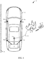
- FIG. 1 shows a system 10 for localizing a wireless node, in accordance with an embodiment of the present disclosure.
- the system 10 includes an automobile 12, which is a physical infrastructure having a variety of electronically controllable functions, controlled by a master transceiver 14.
- a master transceiver 14 controls the locking or unlocking or doors on the automobile 12.
- the master transceiver 14 opens or closes windows on the automobile 12, or controls an entertainment center (e.g., a radio).
- an entertainment center e.g., a radio
- the master transceiver 14 communicates with (e.g., transceives), with a slave transceiver 16 using a wireless communication protocol for transmitting and receiving data.
- the slave transceiver 16 is a key FOB operating with the BLE protocol.
- the master transceiver 14 and the slave transceiver 16 transceive with a Personal Area Network (PAN) protocol, examples of which include but are not limited to the communication protocols based on the family of IEEE 802.15 standards, such as Bluetooth®, WiFi®, ANT®, Zigbee®, and low powered versions of communication protocols, such as BLE, and the like.
- PAN Personal Area Network
- System 10 includes four wideband spectrum-sensing units 20a, 20b, 20c and 20d, (generally 20), mounted on the automobile 12 with sufficient separation to minimize blocking of each of the transmission channels between each of the wideband spectrum-sensing units 20 and the slave transceiver 16 due to an intervening object.
- Various embodiments include different placements and quantities of the wideband spectrum-sensing units 20.
- Each of the wideband spectrum-sensing units 20 and the master transceiver 14 are connected to a processor 22.
- the connection between the processor 22 to each of the wideband spectrum-sensing units 20 and the master transceiver 14 is made over a high speed data bus, such as an automotive Ethernet bus, although other bus protocols are envisioned within the scope of this disclosure.
- the processor 22 is a Digital Signal Processor capable of performing convolutions and correlations between data sets.
- the processor 22 includes a system interface (not shown).
- the system interface includes, but is not limited to, a bidirectional data port for transferring data to or from the processor 22, or a display and keypad interface.
- the slave transceiver 16 communicates with the master transceiver 14 through a channel 24.
- the channel 24 between the slave transceiver and the master transceiver 14 is blocked, for example by the presence of an intervening object such as a human 26.
- the channel 24 includes a multitude of transmission paths (e.g., "multipath"), as a result of reflections from electrically reflective surfaces, such as a reflective wall 28.
- the physical infrastructure is a building (e.g., a home or a shopping mall), with walls, furnishing and the like, each of which can contribute to the formation of multipath channels or blocking of the transmission.
- the wideband spectrum-sensing units 20 Independent of the communication between the slave transceiver 16 and the master transceiver 14, the wideband spectrum-sensing units 20 also receive the transmission from the slave transceiver 16, sampled with a higher bandwidth than the bandwidth of the master transceiver 14. The transmission samples from the wideband spectrum-sensing units 20 are compared with previously determined channel data to form respective power delay profiles, and then TDOA methods are used to determine the slave location of the slave transceiver 16.
- WPAN Wireless PAN
- the sensing locations are stored in a first memory prior to executing the TDOA method.
- the first memory (not shown) is connected to the processor 22.
- the master transceiver 14 also informs each of the wideband spectrum-sensing units 20 as to the channel (e.g., for WPAN protocol), and the start and end time of the transmission received from the slave transceiver 16.
- a WPAN channel is defined by one of a plurality of sequential frequency ranges.
- the master transceiver 14 only provides the start and end time to each of the wideband spectrum-sensing units 20, thereby simplifying the design of the master transceiver 14 and each of the wideband spectrum-sensing units 20 at the expense of processing, with the processor 22, additionally sampled data from more than one channel.
- Each of the wideband spectrum-sensing units 20 and the master transceiver 14 are also temporally synchronized to a time reference, (not shown).
- FIG. 2 shows a plurality of received transmissions 40a, 40b, 40c and 40d, (generally 40), transmitted by the slave transceiver 16 and received by the wideband spectrum-sensing unit 20a.
- the different magnitudes and multipath time delays for each of the received transmissions 40 result from a combination of direct and indirect paths taken by each received transmission 40.
- FIG. 3 shows a plurality of received transmissions 42a, 42b, 42c, 42d, 42e and 42f, (generally 42), transmitted by the slave transceiver 16 and received by the wideband spectrum-sensing unit 20b.
- the different magnitudes and multipath time delays for each of the received transmissions 40 result from a combination of direct and indirect paths taken by each received transmission 40.
- FIG. 4 shows a plurality of received transmissions 44a, 44b, 44c, and 44d, (generally 44), transmitted by the slave transceiver 16 and received by the wideband spectrum-sensing unit 20c.
- the different magnitudes and multipath time delays for each of the received transmissions 40 result from a combination of direct and indirect paths taken by each received transmission 40.
- FIG. 5 shows a plurality of received transmissions 46a, 46b, 46c and 46f, (generally 46), transmitted by the slave transceiver 16 and received by the wideband spectrum-sensing unit 20d.
- the different magnitudes and multipath time delays for each of the received transmissions 40 result from a combination of direct and indirect paths taken by each received transmission 40.
- FIG. 6 shows a flowchart representation of a method for generating a power delay profile 58 for one of the wideband spectrum-sensing units 20 shown in FIG. 1 .
- a plurality of samples 50 (corresponding to one of the group of samples 40, 42, 44 or 46 from FIG. 2 to FIG. 5 ), are stored in a second (buffer) memory by the respective wideband spectrum-sensing unit 20.
- the samples 50 are time limited by the wideband spectrum-sensing unit 20 with a start time 54 and a stop time 56 to reduce the second memory storage requirements and subsequent computation burden by the processor 22.
- the start time 54 and stop time 56 correspond to the start and ending of a transmission from the slave transceiver 16 to the master transceiver 14, wherein the start time 54 and stop time 56 are subsequently transmitted to each of the wideband spectrum-sensing units 20 by the master transceiver 14.
- the start time 54 and stop time 56 include additional time guard bands to ensure that the transmission is fully captured and sampled by each of the wideband spectrum-sensing units 20.
- the samples 50 are retrieved from the second memory by the processor 22 and correlated to a plurality of reconstructed samples 52 to determine each of the transmissions 60a, 60b, 60c, 60d, 60e, 60f, 60g, 60h, 60i and 60j, (generally 60), thereby forming the power delay profile 58.
- Each transmission 60 corresponds to a unique path, (either a direct or multipath), between the slave transceiver 16 and the respective wideband spectrum-sensing unit 20.
- the reconstructed samples 52 are based on previous transmissions received by the wideband spectrum-sensing units 20, and retrieved from a first memory by the processor 22.
- the first memory is connected to, or forms part of, the processor 22.
- the previous samples are stored in the respective wideband spectrum-sensing unit 20.
- the reconstructed samples 52 have an adjusted time resolution to match the samples 50.
- the reconstructed samples 52 are formed prior to the completion of generating the samples 50 (e.g., prior to the stop time 56).
- the correlation of the samples 50 with the reconstructed samples 52 is performed with a convolution method.
- the convolution method is replaced with a Maximum Likelihood method, a Matrix Pencil method or a Set-Theoretic Deconvolution method, to reduce the computational burden on the processor 22 for computing a direct path between the slave transceiver 16 and at least one of the wideband spectrum-sensing units 20a.
- FIG. 7 shows a TDOA method 80 based on trilateration-based particle filtering for determining the slave location of the slave transceiver 16 relative to the automobile 12, from the respective first paths 60a of each of the plurality of power delay profiles 58.
- Other TDOA methods are considered to be within the scope of this disclosure and are not limited by the particle filtering approach.
- the method 80 includes a plurality of distance measurement rings 82a, 82b, 82c and 82d, (generally 82), corresponding to respective wideband spectrum-sensing units 20a, 20b, 20c and 20d.
- the automobile 12 include door zones 90 and 92.
- the various "+" markers 94 show an initial particle distribution, and the "o" markers 96 show converged particles. In the embodiment shown in FIG. 7 , the converged particles 96, show that the slave transceiver 16 is proximate to the door zone 90.
- FIG. 8 shows a system 100 for localizing a wireless node, in accordance with an embodiment of the present disclosure.
- a slave transceiver 102 transmits a transmission with an antenna 104.
- a master transceiver 106 receives the transmission with an antenna 108.
- a plurality of wideband spectrum-sensing units 110a and 110b, (generally 110) also receive the transmission with respective antennas 112a and 112b, (generally 112).
- the master transceiver 106 and each of the wideband spectrum-sensing units 110 have bidirectional communication with a processor 120.
- the processor 120 a system interface 122 and a memory 124.
- the system interface 122 includes a bidirectional port for programming and receiving data from the processor 120. In another embodiment, the system interface 122 includes a display and keypad for modifying programs or settings of the processor 120. In one embodiment, the memory 124 is volatile or non-volatile RAM. In another embodiment, the memory 124 is integrated with the processor 120 having a single semiconductor. In one embodiment, the processor 120 is a Digital Signal Processor, however other processor architectures capable of performing convolutions are envisioned within the scope of this disclosure.
- each of the wideband spectrum-sensing units 110 includes a Filter and Mixer 140 receiving the transmission from the antenna 112.
- the Filter and Mixer 140 limits the bandwidth of the transmission to the Industrial, Scientific and Medical Radio (ISM) band and down coverts the received transmission.
- the output of the Filter and Mixer 140 is sampled by a wideband Analog to Digital Converter (ADC) 142 to provide a plurality of wideband samples.
- ADC Analog to Digital Converter
- the ADC 142 directly samples the transmission received at the antenna 112 to reduce the number of components of each of the wideband spectrum-sensing units 110 at the expense of requiring a more complex ADC 142.
- the wideband ADC 142 oversamples the ISM band to reduce filtering requirements.
- the wideband ADC 142 includes a fixed gain Radio Front End (RFE) receiver to reduce delay variation.
- the ADC 142 does not include an RFE receiver for simplifying the ADC 142 design at the expense of system accuracy.
- the wideband ADC 142 is a 14 bit Sigma-Delta converter sampling with at least 1 Giga-Samples/second.
- the output samples of the wideband ADC 142 are received by pre-processing circuits 144.
- the pre-processing circuits 144 limit the samples received from the wideband ADC 142 by a channel number and acquisition window, prior to storing the limited sample data in a buffer memory 145 (e.g., a second memory).
- a buffer memory 145 e.g., a second memory
- the buffer memory 145 is included with the pre-processing circuits 144.
- the limited sample data are transferred to the processor 120 for storage in the first memory 124.
- Each of the wideband spectrum-sensing unit 110 includes a reference clock 146 configured to be synchronized to each of the wideband spectrum-sensing units 110 and the master transceiver 106 with wired or wireless connections.
- the control settings circuit 148 receives the channel number and acquisition window received from the master transceiver 106. In another embodiment, the control settings circuit 148 receives the channel number, the channel start time and the channel stop time. In an embodiment where the slave transceiver 102 and the master transceiver 106 communicate with the WPAN protocol, the channel number is defined by a frequency range of 2 MHz, being one of a series of consecutive channels defined by the WPAN protocol.
- the acquisition window is defined by the channel start and channel stop time as received by the master transceiver 106.
- the control settings circuit 148 also receives the expected signal type (e.g., a BLE packet or continuous tone extension (CTE)), from the master transceiver 106 for use in determining the angle of arrival of the transmission from the slave transceiver 102.
- the control settings circuit 148 causes one or more of the circuits of the wideband spectrum-sensing unit 110 to exit a low power state upon detecting the channel start by the master transceiver 106, and returning to the low power state after the channel stop.
- FIG. 10 shows a method for localization of a wireless node, in accordance with an embodiment of the present disclosure.
- the master transceiver 106 is synchronized to the time reference (e.g., reference clock) 146.
- each of the wideband spectrum-sensing units 110 is synchronized to the time reference 146.
- the wideband spectrum-sensing units 110 are synchronized to each other to perform the TDOA method, while the master transceiver 106 is synchronized to provide the acquisition window for limiting sample data.
- the physical location of each of the wideband spectrum-sensing units 110 is stored in a first memory 124. In various embodiments, 162, 164 and 166 are performed in parallel or in any sequential combination.
- the slave transceiver 102 transmits a transmission, and at 172 and 174, the master transceiver 106 and each of the wideband spectrum-sensing units 110 respectively receive the transmission.
- the master transceiver 106 decodes the transmission to determine the channel number, channel start time and channel stop time (e.g., to define the acquisition window). In one embodiment at 176, the received transmission is also decoded to determine if the transmission is organized as a BLE packet, a CTE, or other WPAN protocol.
- the master transceiver 106 transmits and each of the wideband spectrum-sensing units 110 respectively receives the channel number and acquisition window (or channel start and channel stop time) decoded at 176.
- the transmission samples limited by the channel and acquisition window from the pre-processing circuits 144 are stored in a memory 124.
- the newly sampled transmission is correlated with the reconstructed samples to form a power delay profile for each of the wideband spectrum-sensing units 110.
- a location of the slave transceiver 102 is determined by applying the TDOA method to power delay profiles from the respective wideband spectrum-sensing units 110.
- a system for localizing a wireless node comprises a master transceiver configured to receive a transmission from a slave transceiver.
- a plurality of wideband spectrum-sensing units are connected to a physical infrastructure, wherein a sensing location of each respective wideband spectrum-sensing unit is stored in a first memory, and a plurality of respective wideband samples of the transmission sampled by each of the wideband spectrum-sensing units is stored in a respective second memory, wherein each of the respective wideband samples are limited by an acquisition window received by each of the wideband spectrum-sensing units from the master transceiver.
- a respective time reference of each of the wideband spectrum-sensing units and the master transceiver are synchronized to a reference clock.
- a processor is connected to the master transceiver and each of the wideband spectrum-sensing units.
- the processor is configured to determine a slave location of the slave transceiver wherein for each of the wideband spectrum-sensing units, the wideband samples from the respective second memory are correlated with a corresponding plurality of reconstructed samples stored in the first memory, to determine a respective power delay profile of the transmission, and the slave location of the slave transceiver is determined relative to the respective sensing locations of the wideband spectrum-sensing units by applying a Time Difference Of Arrival method to the respective power delay profiles.
- Each of the wideband spectrum-sensing units comprise an Analog to Digital Converter (ADC) configured to sample the transmission to generate the plurality of wideband samples, wherein the ADC has an ADC bandwidth greater than a receive bandwidth of the master transceiver.
- the ADC includes a Radio Frequency Front End amplifier having a fixed gain.
- the ADC includes an over-sampling circuit for sampling the transmission, wherein the ADC bandwidth is greater than, or equal to, ten times the receive bandwidth.
- a signal pre-processing circuit is configured to limit an output of the ADC to the acquisition window and the frequency range corresponding to the channel number, to form the plurality of wideband samples.
- the reconstructed samples are determined from a previous transmission received by each of the wideband spectrum-sensing units. Each of the respective wideband samples are further limited by a frequency range corresponding to a channel number.
- the master transceiver and the slave transceiver each transceive with a Wireless Personal Area Network protocol.
- the physical infrastructure is an automobile and the slave transceiver is a key Frequency Operated Button.
- a method for localizing a wireless node comprises synchronizing a respective time reference of a plurality of wideband spectrum-sensing units and a master transceiver, and storing a sensing location of each of the respective wideband spectrum-sensing units in a first memory.
- the master transceiver and each of the wideband spectrum-sensing units receive a transmission from a slave transceiver.
- the master transceiver decodes a channel number, a channel start time and a channel end time from the transmission.
- Each of the wideband spectrum-sensing units receive from the master transceiver, the channel number, the channel start time and the channel end time of the transmission, wherein an acquisition window begins at the channel start time and ends at the channel end time.
- a plurality of respective wideband samples of the transmission received by each of the wideband spectrum-sensing units during the acquisition window are stored in a respective second memory, wherein each of the respective wideband samples are limited by a frequency range corresponding to the channel number.
- the wideband samples from the respective second memory are correlated with a corresponding plurality of reconstructed samples stored in the first memory to form a respective power delay profile of the transmission.
- a slave location of the slave transceiver relative to the respective sensing locations of the wideband spectrum-sensing units is determined by applying a Time Difference Of Arrival method to the respective power delay profiles.
- Alternative embodiments of the method for localizing a wireless node include one of the following features, or any combination thereof.
- the transmission is sampled with an Analog to Digital Converter to generate the plurality of wideband samples.
- a low power state of the wideband spectrum-sensing units is exited in response to the master transceiver receiving the transmission and communicating an activity status from the master transceiver to each of the wideband spectrum-sensing units.
- the reconstructed samples are determined from a previous transmission received by each of the wideband spectrum-sensing units.
- Each power delay profile includes a plurality of signals having a respective magnitude and multipath time delay, each signal corresponding to a respective path between the slave transceiver and the respective wideband spectrum-sensing unit.
- a direct path between the slave transceiver and the respective wideband spectrum-sensing unit is determined from the respective path with the shortest multipath time delay.
- An object location of an intervening object between the slave transceiver and the respective wideband spectrum-sensing unit is determined from at least one indirect path of the power delay profile.
- a physical environment is mapped from a plurality of object locations of respective intervening objects between the slave transceiver and the respective wideband spectrum-sensing unit, wherein the object locations are determined by one or more indirect paths of the power delay profile.
- a method for localizing a wireless node comprises receiving by each of a plurality of wideband spectrum-sensing units, from a master transceiver, a channel start time and a channel end time of a transmission from a slave transceiver received by the master transceiver, wherein a sensing location of each of the wideband spectrum-sensing units is stored in a first memory, and each of the wideband spectrum-sensing units and the master transceiver is synchronized to a time reference.
- a plurality of respective wideband samples of the transmission received by each of the wideband spectrum-sensing units starting at the channel start time and ending at the channel end time is stored in a respective second memory, each of the respective wideband samples are generated by an Analog to Digital Converter.
- the wideband samples from the respective second memory are correlated with a corresponding plurality of reconstructed samples stored in the first memory to form a respective power delay profile of the transmission.
- a slave location of the slave transceiver relative to the respective physical locations of the wideband spectrum-sensing units is determined by applying a Time Difference Of Arrival method to the respective power delay profiles.
- the master transceiver and the slave transceiver each transceive with a Wireless Personal Area Network protocol.
- the master transceiver has a narrow bandwidth being less than a respective bandwidth of each of the wideband spectrum-sending units.
- a method for localizing a wireless node includes synchronizing a respective time reference of a plurality of wideband spectrum-sensing units and a master transceiver.
- a sensing location of each wideband spectrum-sensing unit is stored in a first memory.
- Each wideband spectrum-sensing unit stores in a second memory a plurality of time-limited samples of a transmission received from a slave transceiver.
- the time limit of the transmission is determined by the master transceiver, receiving the transmission.
- the samples from the second memory are correlated with a corresponding plurality of reconstructed samples stored in the first memory to form a respective power delay profile for each of the of the wideband spectrum-sensing units.
- a slave location of the slave transceiver is determined by applying a Time Difference Of Arrival method to the respective power delay profiles.
Landscapes
- Engineering & Computer Science (AREA)
- Radar, Positioning & Navigation (AREA)
- Remote Sensing (AREA)
- Physics & Mathematics (AREA)
- General Physics & Mathematics (AREA)
- Computer Networks & Wireless Communication (AREA)
- Signal Processing (AREA)
- Electromagnetism (AREA)
- Mobile Radio Communication Systems (AREA)
Abstract
Description
- This disclosure relates generally to localization of wireless nodes, and more specifically to localization of wireless nodes with wideband spectrum sensing and correlation to historical channel data.
- Accurate localization of a wireless transmitter with respect to an infrastructure is difficult to achieve by using traditional techniques. Localizing a wireless node can be achieved by triangulation techniques based on a Received Signal Strength Indication (RSSI), however the accuracy is limited by the transceiver bandwidth of the wireless transmitter. Furthermore, techniques based on RSSI, Time of Flight (ToF) or phase-based ranging techniques suffer from multipath and/or non Line of Sight (nLOS) constraints. Specifically, a transmission from the wireless transmitter to a wireless receiver can result in multiple copies of the same transmission arriving at the wireless receiver with undesirable constructive or destructive interference due to the various amplitudes and delays caused by multipath interference. Alternatively an nLOS constraint can result in a single delayed copy from the transmission being indirectly reflected by an intervening object.
- Attempts to mitigate the aforementioned limitations have included the use of additional wireless receivers, repetitive measurements and combining techniques (e.g., RSSI and ToF). Performing repetitive measurements and using additional receivers with one or more localization techniques leads to additional power dissipation, and complexity. Furthermore, existing standards such as Bluetooth® Low Energy (BLE) have limited support for ranging techniques, and remain limited in accurately resolving the location of the wireless node due to bandwidth limitations.
- Aspects of the disclosure are defined in the accompanying claims.
- In a first aspect, there is provided a system for localizing a wireless node comprising:
- a master transceiver configured to receive a transmission from a slave transceiver;
- a plurality of wideband spectrum-sensing units connected to a physical infrastructure, wherein a sensing location of each respective wideband spectrum-sensing unit is stored in a first memory, and a plurality of respective wideband samples of the transmission sampled by each of the wideband spectrum-sensing units is stored in a respective second memory, wherein each of the respective wideband samples are limited by an acquisition window, received by each of the wideband spectrum-sensing units from the master transceiver;
- a respective time reference of each of the wideband spectrum-sensing units and the master transceiver synchronized to a reference clock; and
- a processor connected to the master transceiver and each of the wideband spectrum-sensing units, the processor configured to determine a slave location of the slave transceiver wherein:
- for each of the wideband spectrum-sensing units, the wideband samples from the respective second memory are correlated with a corresponding plurality of reconstructed samples stored in the first memory, to determine a respective power delay profile of the transmission, and
- the slave location of the slave transceiver is determined relative to the respective sensing locations of the wideband spectrum-sensing units by applying a Time Difference Of Arrival method to the respective power delay profiles.
- In one or more embodiments, each of the wideband spectrum-sensing units may comprise an Analog to Digital Converter (ADC) configured to sample the transmission to generate the plurality of wideband samples, wherein the ADC has an ADC bandwidth greater than a receive bandwidth of the master transceiver.
- In one or more embodiments, the ADC may include a Radio Frequency Front End amplifier having a fixed gain.
- In one or more embodiments, the ADC may include an over-sampling circuit for sampling the transmission, wherein the ADC bandwidth is greater than, or equal to, ten times the receive bandwidth.
- In one or more embodiments, the system may further comprise a signal pre-processing circuit configured to limit an output of the ADC to the acquisition window and the frequency range corresponding to the channel number, to form the plurality of wideband samples.
- In one or more embodiments, the reconstructed samples may be determined from a previous transmission received by each of the wideband spectrum-sensing units.
- In one or more embodiments, each of the respective wideband samples may be further limited by a frequency range corresponding to a channel number.
- In one or more embodiments, the master transceiver and the slave transceiver each may transceive with a Wireless Personal Area Network protocol.
- In one or more embodiments, the physical infrastructure may be an automobile and the slave transceiver is a key Frequency Operated Button.
- In a second aspect, there is provided a method for localizing a wireless node comprising:
- synchronizing a respective time reference of a plurality of wideband spectrum-sensing units and a master transceiver, and storing a sensing location of each of the respective wideband spectrum-sensing units in a first memory;
- receiving by the master transceiver and each of the wideband spectrum-sensing units, a transmission from a slave transceiver;
- decoding by the master transceiver, a channel number, a channel start time and a channel end time from the transmission;
- receiving by each of the wideband spectrum-sensing units, from the master transceiver, the channel number, the channel start time and the channel end time of the transmission, wherein an acquisition window begins at the channel start time and ends at the channel end time;
- storing in a respective second memory, a plurality of respective wideband samples of the transmission received by each of the wideband spectrum-sensing units during the acquisition window, wherein each of the respective wideband samples are limited by a frequency range corresponding to the channel number;
- for each of the wideband spectrum-sensing units, correlating the wideband samples from the respective second memory with a corresponding plurality of reconstructed samples stored in the first memory to form a respective power delay profile of the transmission; and
- determining a slave location of the slave transceiver relative to the respective sensing locations of the wideband spectrum-sensing units by applying a Time Difference Of Arrival method to the respective power delay profiles.
- In one or more embodiments, the method may further comprise sampling the transmission with an Analog to Digital Converter to generate the plurality of wideband samples.
- In one or more embodiments, the method may further comprise exiting a low power state of the wideband spectrum-sensing units in response to the master transceiver receiving the transmission and communicating an activity status from the master transceiver to each of the wideband spectrum-sensing units.
- In one or more embodiments, the method may further comprise determining the reconstructed samples from a previous transmission received by each of the wideband spectrum-sensing units.
- In one or more embodiments, each power delay profile may include a plurality of signals having a respective magnitude and multipath time delay, each signal corresponding to a respective path between the slave transceiver and the respective wideband spectrum-sensing unit.
- In one or more embodiments, the method may further comprise determining a direct path between the slave transceiver and the respective wideband spectrum-sensing unit from the respective path with the shortest multipath time delay.
- In one or more embodiments, the method may further comprise determining an object location of an intervening object between the slave transceiver and the respective wideband spectrum-sensing unit from at least one indirect path of the power delay profile.
- In one or more embodiments, the method may further comprise mapping a physical environment from a plurality of object locations of respective intervening objects between the slave transceiver and the respective wideband spectrum-sensing unit, wherein the object locations are determined by one or more indirect paths of the power delay profile.
- In a third aspect, there is provided a method for localizing a wireless node comprising:
- receiving by each of a plurality of wideband spectrum-sensing units, from a master transceiver, a channel start time and a channel end time of a transmission from a slave transceiver received by the master transceiver, wherein a sensing location of each of the wideband spectrum-sensing units is stored in a first memory, and each of the wideband spectrum-sensing units and the master transceiver is synchronized to a time reference;
- storing in a respective second memory, a plurality of respective wideband samples of the transmission received by each of the wideband spectrum-sensing units starting at the channel start time and ending at the channel end time, wherein each of the respective wideband samples are generated by an Analog to Digital Converter;
- for each of the wideband spectrum-sensing units, correlating the wideband samples from the respective second memory with a corresponding plurality of reconstructed samples stored in the first memory to form a respective power delay profile of the transmission; and
- determining a slave location of the slave transceiver relative to the respective physical locations of the wideband spectrum-sensing units by applying a Time Difference Of Arrival method to the respective power delay profiles.
- In one or more embodiments, the master transceiver and the slave transceiver each may transceive with a Wireless Personal Area Network protocol.
- In one or more embodiments, the master transceiver may have a narrow bandwidth being less than a respective bandwidth of each of the wideband spectrum-sending units.
- The present invention is illustrated by way of example and is not limited by the accompanying figures, in which like references indicate similar elements. Elements in the figures are illustrated for simplicity and clarity and have not necessarily been drawn to scale.
-
FIG. 1 is a plan view of a system for localizing a wireless node, in accordance with an embodiment of the present disclosure. -
FIG. 2, FIG. 3, FIG. 4 and FIG. 5 are graphical views of the channel response measured by each of the four wideband spectrum-sensing units shown inFIG. 1 . -
FIG. 6 is a flowchart representation of a method for generating a power delay profile for one of the wideband spectrum-sensing units shown inFIG. 1 . -
FIG. 7 is plan view of a vehicle showing a Time Difference of Arrival method using particle distribution to determine a location of a wireless node. -
FIG. 8 is a functional block view of a system for localizing a wireless node, in accordance with an embodiment of the present disclosure. -
FIG. 9 is a functional block view of the wideband spectrum-sensing unit shown inFIG. 8 , in accordance with an embodiment of the present disclosure. -
FIG. 10 is a flowchart representation of a method for localization of a wireless node, in accordance with an embodiment of the present disclosure. - Embodiments of systems and methods described herein provide for determining an accurate location of a wireless node relative to an infrastructure. The location is determined with at least two wideband spectrum-sensing units that are synchronized in time and have defined locations on the infrastructure. The wideband spectrum-sensing units perform wideband measurements of a transmission from the wireless node through a channel to a wireless receiver, in an unobtrusive manner. The plurality of wideband measurements are further correlated with previously determined channel information and combined with a Time Difference Of Arrival (TDOA) method to determine the location of the wireless node. In addition, the localization method enables environmental mapping as well as the detection of potential spoofing attempts to access the wireless receiver.
- In one example embodiment, a wireless node includes a key Frequency Operated Button (FOB) and the infrastructure is an automobile. By determining an accurate location of the key FOB, the key FOB can unlock specific doors on the automobile, or perform other location specific tasks. In another example, a phone location can be determined relative to the automobile. Determination of direct and indirect paths between the wireless transmitter and the wireless receiver enables mapping of the channel environment including the infrastructure, transmitter, receiver, and intervening objects, which contribute to multipath. In one embodiment, specific features of the channel environment are compared to previous determinations, or prerecorded scenarios, of the environment to detect the presence of an occupant in the automobile or an open door, for example. In another embodiment, the signal characteristics (e.g., strength and location), of the detected key FOB are used to detect spoofing attempts at gaining access to the wireless receiver with an intervening device.
-
FIG. 1 shows asystem 10 for localizing a wireless node, in accordance with an embodiment of the present disclosure. Thesystem 10 includes anautomobile 12, which is a physical infrastructure having a variety of electronically controllable functions, controlled by amaster transceiver 14. For example, in one embodiment themaster transceiver 14 controls the locking or unlocking or doors on theautomobile 12. In another embodiment, themaster transceiver 14 opens or closes windows on theautomobile 12, or controls an entertainment center (e.g., a radio). - The
master transceiver 14 communicates with (e.g., transceives), with aslave transceiver 16 using a wireless communication protocol for transmitting and receiving data. In one embodiment, theslave transceiver 16 is a key FOB operating with the BLE protocol. In other embodiments, themaster transceiver 14 and theslave transceiver 16 transceive with a Personal Area Network (PAN) protocol, examples of which include but are not limited to the communication protocols based on the family of IEEE 802.15 standards, such as Bluetooth®, WiFi®, ANT®, Zigbee®, and low powered versions of communication protocols, such as BLE, and the like.System 10 includes four wideband spectrum-sensingunits automobile 12 with sufficient separation to minimize blocking of each of the transmission channels between each of the wideband spectrum-sensingunits 20 and theslave transceiver 16 due to an intervening object. Various embodiments include different placements and quantities of the wideband spectrum-sensingunits 20. - Each of the wideband spectrum-sensing
units 20 and themaster transceiver 14 are connected to aprocessor 22. In one embodiment, the connection between theprocessor 22 to each of the wideband spectrum-sensingunits 20 and themaster transceiver 14 is made over a high speed data bus, such as an automotive Ethernet bus, although other bus protocols are envisioned within the scope of this disclosure. In one embodiment, theprocessor 22 is a Digital Signal Processor capable of performing convolutions and correlations between data sets. In various embodiments, theprocessor 22 includes a system interface (not shown). In example embodiments, the system interface includes, but is not limited to, a bidirectional data port for transferring data to or from theprocessor 22, or a display and keypad interface. - The
slave transceiver 16 communicates with themaster transceiver 14 through achannel 24. In various embodiments, thechannel 24 between the slave transceiver and themaster transceiver 14 is blocked, for example by the presence of an intervening object such as a human 26. In other embodiments, thechannel 24 includes a multitude of transmission paths (e.g., "multipath"), as a result of reflections from electrically reflective surfaces, such as areflective wall 28. In another embodiment, the physical infrastructure is a building (e.g., a home or a shopping mall), with walls, furnishing and the like, each of which can contribute to the formation of multipath channels or blocking of the transmission. - The presence of both direct and multipath signals and the limited bandwidth of a Wireless PAN (WPAN) protocol based transceiver limits the ability to accurately locate the
slave transceiver 16. Independent of the communication between theslave transceiver 16 and themaster transceiver 14, the wideband spectrum-sensingunits 20 also receive the transmission from theslave transceiver 16, sampled with a higher bandwidth than the bandwidth of themaster transceiver 14. The transmission samples from the wideband spectrum-sensingunits 20 are compared with previously determined channel data to form respective power delay profiles, and then TDOA methods are used to determine the slave location of theslave transceiver 16. - The sensing locations are stored in a first memory prior to executing the TDOA method. In one embodiment, the first memory (not shown) is connected to the
processor 22. In one embodiment, themaster transceiver 14 also informs each of the wideband spectrum-sensingunits 20 as to the channel (e.g., for WPAN protocol), and the start and end time of the transmission received from theslave transceiver 16. A WPAN channel is defined by one of a plurality of sequential frequency ranges. In another embodiment, themaster transceiver 14 only provides the start and end time to each of the wideband spectrum-sensingunits 20, thereby simplifying the design of themaster transceiver 14 and each of the wideband spectrum-sensingunits 20 at the expense of processing, with theprocessor 22, additionally sampled data from more than one channel. Each of the wideband spectrum-sensingunits 20 and themaster transceiver 14 are also temporally synchronized to a time reference, (not shown). - Referring now to
FIG. 2 to FIG. 5 , with continued reference toFIG. 1 , the measured channel response is shown for each of the wideband spectrum-sensingunits 20 ofFIG. 1 . Specifically,FIG. 2 shows a plurality of receivedtransmissions slave transceiver 16 and received by the wideband spectrum-sensing unit 20a. The different magnitudes and multipath time delays for each of the received transmissions 40 result from a combination of direct and indirect paths taken by each received transmission 40. -
FIG. 3 shows a plurality of receivedtransmissions slave transceiver 16 and received by the wideband spectrum-sensing unit 20b. The different magnitudes and multipath time delays for each of the received transmissions 40 result from a combination of direct and indirect paths taken by each received transmission 40. -
FIG. 4 shows a plurality of receivedtransmissions slave transceiver 16 and received by the wideband spectrum-sensing unit 20c. The different magnitudes and multipath time delays for each of the received transmissions 40 result from a combination of direct and indirect paths taken by each received transmission 40. -
FIG. 5 shows a plurality of receivedtransmissions slave transceiver 16 and received by the wideband spectrum-sensing unit 20d. The different magnitudes and multipath time delays for each of the received transmissions 40 result from a combination of direct and indirect paths taken by each received transmission 40. -
FIG. 6 shows a flowchart representation of a method for generating apower delay profile 58 for one of the wideband spectrum-sensingunits 20 shown inFIG. 1 . A plurality ofsamples 50, (corresponding to one of the group of samples 40, 42, 44 or 46 fromFIG. 2 to FIG. 5 ), are stored in a second (buffer) memory by the respective wideband spectrum-sensingunit 20. Thesamples 50 are time limited by the wideband spectrum-sensingunit 20 with astart time 54 and astop time 56 to reduce the second memory storage requirements and subsequent computation burden by theprocessor 22. In one embodiment, thestart time 54 andstop time 56 correspond to the start and ending of a transmission from theslave transceiver 16 to themaster transceiver 14, wherein thestart time 54 andstop time 56 are subsequently transmitted to each of the wideband spectrum-sensingunits 20 by themaster transceiver 14. In various embodiments, thestart time 54 andstop time 56 include additional time guard bands to ensure that the transmission is fully captured and sampled by each of the wideband spectrum-sensingunits 20. - The
samples 50 are retrieved from the second memory by theprocessor 22 and correlated to a plurality of reconstructedsamples 52 to determine each of thetransmissions power delay profile 58. Each transmission 60 corresponds to a unique path, (either a direct or multipath), between theslave transceiver 16 and the respective wideband spectrum-sensingunit 20. Thereconstructed samples 52 are based on previous transmissions received by the wideband spectrum-sensingunits 20, and retrieved from a first memory by theprocessor 22. In one embodiment, the first memory is connected to, or forms part of, theprocessor 22. In another embodiment, the previous samples are stored in the respective wideband spectrum-sensingunit 20. Thereconstructed samples 52 have an adjusted time resolution to match thesamples 50. In one embodiment thereconstructed samples 52 are formed prior to the completion of generating the samples 50 (e.g., prior to the stop time 56). - In one embodiment, the correlation of the
samples 50 with thereconstructed samples 52 is performed with a convolution method. In other embodiments, the convolution method is replaced with a Maximum Likelihood method, a Matrix Pencil method or a Set-Theoretic Deconvolution method, to reduce the computational burden on theprocessor 22 for computing a direct path between theslave transceiver 16 and at least one of the wideband spectrum-sensingunits 20a. -
FIG. 7 shows aTDOA method 80 based on trilateration-based particle filtering for determining the slave location of theslave transceiver 16 relative to theautomobile 12, from the respectivefirst paths 60a of each of the plurality of power delay profiles 58. Other TDOA methods are considered to be within the scope of this disclosure and are not limited by the particle filtering approach. Themethod 80, includes a plurality of distance measurement rings 82a, 82b, 82c and 82d, (generally 82), corresponding to respective wideband spectrum-sensingunits automobile 12 includedoor zones markers 94 show an initial particle distribution, and the "o"markers 96 show converged particles. In the embodiment shown inFIG. 7 , the convergedparticles 96, show that theslave transceiver 16 is proximate to thedoor zone 90. -
FIG. 8 shows asystem 100 for localizing a wireless node, in accordance with an embodiment of the present disclosure. Aslave transceiver 102 transmits a transmission with an antenna 104. Amaster transceiver 106 receives the transmission with anantenna 108. A plurality of wideband spectrum-sensingunits respective antennas master transceiver 106 and each of the wideband spectrum-sensingunits 110 have bidirectional communication with aprocessor 120. In various embodiments, the processor 120 asystem interface 122 and amemory 124. - In one embodiment, the
system interface 122 includes a bidirectional port for programming and receiving data from theprocessor 120. In another embodiment, thesystem interface 122 includes a display and keypad for modifying programs or settings of theprocessor 120. In one embodiment, thememory 124 is volatile or non-volatile RAM. In another embodiment, thememory 124 is integrated with theprocessor 120 having a single semiconductor. In one embodiment, theprocessor 120 is a Digital Signal Processor, however other processor architectures capable of performing convolutions are envisioned within the scope of this disclosure. - Referring to
FIG. 9 , with continued reference toFIG. 8 , each of the wideband spectrum-sensingunits 110 are described in further detail. In one embodiment, each of the wideband spectrum-sensingunits 110 includes a Filter andMixer 140 receiving the transmission from theantenna 112. In an example embodiment, the Filter andMixer 140 limits the bandwidth of the transmission to the Industrial, Scientific and Medical Radio (ISM) band and down coverts the received transmission. The output of the Filter andMixer 140 is sampled by a wideband Analog to Digital Converter (ADC) 142 to provide a plurality of wideband samples. In another embodiment, theADC 142 directly samples the transmission received at theantenna 112 to reduce the number of components of each of the wideband spectrum-sensingunits 110 at the expense of requiring a morecomplex ADC 142. In an example embodiment, thewideband ADC 142 oversamples the ISM band to reduce filtering requirements. In various embodiments, thewideband ADC 142 includes a fixed gain Radio Front End (RFE) receiver to reduce delay variation. In other embodiments, theADC 142 does not include an RFE receiver for simplifying theADC 142 design at the expense of system accuracy. In the example embodiment, thewideband ADC 142 is a 14 bit Sigma-Delta converter sampling with at least 1 Giga-Samples/second. - The output samples of the
wideband ADC 142 are received by pre-processingcircuits 144. Thepre-processing circuits 144 limit the samples received from thewideband ADC 142 by a channel number and acquisition window, prior to storing the limited sample data in a buffer memory 145 (e.g., a second memory). In an example embodiment, thebuffer memory 145 is included with thepre-processing circuits 144. In another embodiment, the limited sample data are transferred to theprocessor 120 for storage in thefirst memory 124. - Each of the wideband spectrum-
sensing unit 110 includes areference clock 146 configured to be synchronized to each of the wideband spectrum-sensingunits 110 and themaster transceiver 106 with wired or wireless connections. In one embodiment, thecontrol settings circuit 148 receives the channel number and acquisition window received from themaster transceiver 106. In another embodiment, thecontrol settings circuit 148 receives the channel number, the channel start time and the channel stop time. In an embodiment where theslave transceiver 102 and themaster transceiver 106 communicate with the WPAN protocol, the channel number is defined by a frequency range of 2 MHz, being one of a series of consecutive channels defined by the WPAN protocol. The acquisition window is defined by the channel start and channel stop time as received by themaster transceiver 106. In another embodiment, thecontrol settings circuit 148 also receives the expected signal type (e.g., a BLE packet or continuous tone extension (CTE)), from themaster transceiver 106 for use in determining the angle of arrival of the transmission from theslave transceiver 102. In another example embodiment, thecontrol settings circuit 148 causes one or more of the circuits of the wideband spectrum-sensing unit 110 to exit a low power state upon detecting the channel start by themaster transceiver 106, and returning to the low power state after the channel stop. -
FIG. 10 , with continued reference toFIG. 8 andFIG. 9 , shows a method for localization of a wireless node, in accordance with an embodiment of the present disclosure. At 162, themaster transceiver 106 is synchronized to the time reference (e.g., reference clock) 146. At 164, each of the wideband spectrum-sensingunits 110 is synchronized to thetime reference 146. The wideband spectrum-sensingunits 110 are synchronized to each other to perform the TDOA method, while themaster transceiver 106 is synchronized to provide the acquisition window for limiting sample data. At 166, the physical location of each of the wideband spectrum-sensingunits 110 is stored in afirst memory 124. In various embodiments, 162, 164 and 166 are performed in parallel or in any sequential combination. - At 170, the
slave transceiver 102 transmits a transmission, and at 172 and 174, themaster transceiver 106 and each of the wideband spectrum-sensingunits 110 respectively receive the transmission. At 176, themaster transceiver 106 decodes the transmission to determine the channel number, channel start time and channel stop time (e.g., to define the acquisition window). In one embodiment at 176, the received transmission is also decoded to determine if the transmission is organized as a BLE packet, a CTE, or other WPAN protocol. At 180 and 182, themaster transceiver 106 transmits and each of the wideband spectrum-sensingunits 110 respectively receives the channel number and acquisition window (or channel start and channel stop time) decoded at 176. At 184, the transmission samples limited by the channel and acquisition window from thepre-processing circuits 144 are stored in amemory 124. At 186, the newly sampled transmission is correlated with the reconstructed samples to form a power delay profile for each of the wideband spectrum-sensingunits 110. At 188, a location of theslave transceiver 102 is determined by applying the TDOA method to power delay profiles from the respective wideband spectrum-sensingunits 110. - As will be appreciated, embodiments as disclosed include at least the following. In one embodiment, a system for localizing a wireless node comprises a master transceiver configured to receive a transmission from a slave transceiver. A plurality of wideband spectrum-sensing units are connected to a physical infrastructure, wherein a sensing location of each respective wideband spectrum-sensing unit is stored in a first memory, and a plurality of respective wideband samples of the transmission sampled by each of the wideband spectrum-sensing units is stored in a respective second memory, wherein each of the respective wideband samples are limited by an acquisition window received by each of the wideband spectrum-sensing units from the master transceiver. A respective time reference of each of the wideband spectrum-sensing units and the master transceiver are synchronized to a reference clock. A processor is connected to the master transceiver and each of the wideband spectrum-sensing units. The processor is configured to determine a slave location of the slave transceiver wherein for each of the wideband spectrum-sensing units, the wideband samples from the respective second memory are correlated with a corresponding plurality of reconstructed samples stored in the first memory, to determine a respective power delay profile of the transmission, and the slave location of the slave transceiver is determined relative to the respective sensing locations of the wideband spectrum-sensing units by applying a Time Difference Of Arrival method to the respective power delay profiles.
- Alternative embodiments of the system for localizing a wireless node include one of the following features, or any combination thereof. Each of the wideband spectrum-sensing units comprise an Analog to Digital Converter (ADC) configured to sample the transmission to generate the plurality of wideband samples, wherein the ADC has an ADC bandwidth greater than a receive bandwidth of the master transceiver. The ADC includes a Radio Frequency Front End amplifier having a fixed gain. The ADC includes an over-sampling circuit for sampling the transmission, wherein the ADC bandwidth is greater than, or equal to, ten times the receive bandwidth. A signal pre-processing circuit is configured to limit an output of the ADC to the acquisition window and the frequency range corresponding to the channel number, to form the plurality of wideband samples. The reconstructed samples are determined from a previous transmission received by each of the wideband spectrum-sensing units. Each of the respective wideband samples are further limited by a frequency range corresponding to a channel number. The master transceiver and the slave transceiver each transceive with a Wireless Personal Area Network protocol. The physical infrastructure is an automobile and the slave transceiver is a key Frequency Operated Button.
- In another embodiment, a method for localizing a wireless node comprises synchronizing a respective time reference of a plurality of wideband spectrum-sensing units and a master transceiver, and storing a sensing location of each of the respective wideband spectrum-sensing units in a first memory. The master transceiver and each of the wideband spectrum-sensing units receive a transmission from a slave transceiver. The master transceiver decodes a channel number, a channel start time and a channel end time from the transmission. Each of the wideband spectrum-sensing units receive from the master transceiver, the channel number, the channel start time and the channel end time of the transmission, wherein an acquisition window begins at the channel start time and ends at the channel end time. A plurality of respective wideband samples of the transmission received by each of the wideband spectrum-sensing units during the acquisition window are stored in a respective second memory, wherein each of the respective wideband samples are limited by a frequency range corresponding to the channel number. For each of the wideband spectrum-sensing units, the wideband samples from the respective second memory are correlated with a corresponding plurality of reconstructed samples stored in the first memory to form a respective power delay profile of the transmission. A slave location of the slave transceiver relative to the respective sensing locations of the wideband spectrum-sensing units is determined by applying a Time Difference Of Arrival method to the respective power delay profiles.
- Alternative embodiments of the method for localizing a wireless node include one of the following features, or any combination thereof. The transmission is sampled with an Analog to Digital Converter to generate the plurality of wideband samples. A low power state of the wideband spectrum-sensing units is exited in response to the master transceiver receiving the transmission and communicating an activity status from the master transceiver to each of the wideband spectrum-sensing units. The reconstructed samples are determined from a previous transmission received by each of the wideband spectrum-sensing units. Each power delay profile includes a plurality of signals having a respective magnitude and multipath time delay, each signal corresponding to a respective path between the slave transceiver and the respective wideband spectrum-sensing unit. A direct path between the slave transceiver and the respective wideband spectrum-sensing unit is determined from the respective path with the shortest multipath time delay. An object location of an intervening object between the slave transceiver and the respective wideband spectrum-sensing unit is determined from at least one indirect path of the power delay profile. A physical environment is mapped from a plurality of object locations of respective intervening objects between the slave transceiver and the respective wideband spectrum-sensing unit, wherein the object locations are determined by one or more indirect paths of the power delay profile.
- In another embodiment, a method for localizing a wireless node comprises receiving by each of a plurality of wideband spectrum-sensing units, from a master transceiver, a channel start time and a channel end time of a transmission from a slave transceiver received by the master transceiver, wherein a sensing location of each of the wideband spectrum-sensing units is stored in a first memory, and each of the wideband spectrum-sensing units and the master transceiver is synchronized to a time reference. A plurality of respective wideband samples of the transmission received by each of the wideband spectrum-sensing units starting at the channel start time and ending at the channel end time is stored in a respective second memory, each of the respective wideband samples are generated by an Analog to Digital Converter. For each of the wideband spectrum-sensing units, the wideband samples from the respective second memory are correlated with a corresponding plurality of reconstructed samples stored in the first memory to form a respective power delay profile of the transmission. A slave location of the slave transceiver relative to the respective physical locations of the wideband spectrum-sensing units is determined by applying a Time Difference Of Arrival method to the respective power delay profiles.
- Alternative embodiments of the method for localizing a wireless node include one of the following features, or any combination thereof. The master transceiver and the slave transceiver each transceive with a Wireless Personal Area Network protocol. The master transceiver has a narrow bandwidth being less than a respective bandwidth of each of the wideband spectrum-sending units.
- A method for localizing a wireless node includes synchronizing a respective time reference of a plurality of wideband spectrum-sensing units and a master transceiver. A sensing location of each wideband spectrum-sensing unit is stored in a first memory. Each wideband spectrum-sensing unit stores in a second memory a plurality of time-limited samples of a transmission received from a slave transceiver. The time limit of the transmission is determined by the master transceiver, receiving the transmission. The samples from the second memory are correlated with a corresponding plurality of reconstructed samples stored in the first memory to form a respective power delay profile for each of the of the wideband spectrum-sensing units. A slave location of the slave transceiver is determined by applying a Time Difference Of Arrival method to the respective power delay profiles.
- Although the invention is described herein with reference to specific embodiments, various modifications and changes can be made without departing from the scope of the present invention as set forth in the claims below. Accordingly, the specification and figures are to be regarded in an illustrative rather than a restrictive sense, and all such modifications are intended to be included within the scope of the present invention. Any benefits, advantages, or solutions to problems that are described herein with regard to specific embodiments are not intended to be construed as a critical, required, or essential feature or element of any or all the claims.
- Unless stated otherwise, terms such as "first" and "second" are used to arbitrarily distinguish between the elements such terms describe. Thus, these terms are not necessarily intended to indicate temporal or other prioritization of such elements.
Claims (15)
- A system for localizing a wireless node comprising:a master transceiver configured to receive a transmission from a slave transceiver;a plurality of wideband spectrum-sensing units connected to a physical infrastructure, wherein a sensing location of each respective wideband spectrum-sensing unit is stored in a first memory, and a plurality of respective wideband samples of the transmission sampled by each of the wideband spectrum-sensing units is stored in a respective second memory, wherein each of the respective wideband samples are limited by an acquisition window, received by each of the wideband spectrum-sensing units from the master transceiver;a respective time reference of each of the wideband spectrum-sensing units and the master transceiver synchronized to a reference clock; anda processor connected to the master transceiver and each of the wideband spectrum-sensing units, the processor configured to determine a slave location of the slave transceiver wherein:for each of the wideband spectrum-sensing units, the wideband samples from the respective second memory are correlated with a corresponding plurality of reconstructed samples stored in the first memory, to determine a respective power delay profile of the transmission, andthe slave location of the slave transceiver is determined relative to the respective sensing locations of the wideband spectrum-sensing units by applying a Time Difference Of Arrival method to the respective power delay profiles.
- The system of claim 1 wherein each of the wideband spectrum-sensing units comprise an Analog to Digital Converter (ADC) configured to sample the transmission to generate the plurality of wideband samples, wherein the ADC has an ADC bandwidth greater than a receive bandwidth of the master transceiver.
- The system of claim 2 wherein the ADC includes a Radio Frequency Front End amplifier having a fixed gain.
- The system of claim 2 or 3 wherein the ADC includes an over-sampling circuit for sampling the transmission, wherein the ADC bandwidth is greater than, or equal to, ten times the receive bandwidth..
- The system of any of claims 2 to 4 further comprising a signal pre-processing circuit configured to limit an output of the ADC to the acquisition window and the frequency range corresponding to the channel number, to form the plurality of wideband samples.
- The system of any preceding claim wherein the reconstructed samples are determined from a previous transmission received by each of the wideband spectrum-sensing units.
- The system of any preceding claim wherein each of the respective wideband samples are further limited by a frequency range corresponding to a channel number.
- The system of any preceding claim wherein the master transceiver and the slave transceiver each transceive with a Wireless Personal Area Network protocol.
- The system of any preceding claim wherein the physical infrastructure is an automobile and the slave transceiver is a key Frequency Operated Button.
- A method for localizing a wireless node comprising:synchronizing a respective time reference of a plurality of wideband spectrum-sensing units and a master transceiver, and storing a sensing location of each of the respective wideband spectrum-sensing units in a first memory;receiving by the master transceiver and each of the wideband spectrum-sensing units, a transmission from a slave transceiver;decoding by the master transceiver, a channel number, a channel start time and a channel end time from the transmission;receiving by each of the wideband spectrum-sensing units, from the master transceiver, the channel number, the channel start time and the channel end time of the transmission, wherein an acquisition window begins at the channel start time and ends at the channel end time;storing in a respective second memory, a plurality of respective wideband samples of the transmission received by each of the wideband spectrum-sensing units during the acquisition window, wherein each of the respective wideband samples are limited by a frequency range corresponding to the channel number;for each of the wideband spectrum-sensing units, correlating the wideband samples from the respective second memory with a corresponding plurality of reconstructed samples stored in the first memory to form a respective power delay profile of the transmission; anddetermining a slave location of the slave transceiver relative to the respective sensing locations of the wideband spectrum-sensing units by applying a Time Difference Of Arrival method to the respective power delay profiles.
- The method of claim 10 further comprising sampling the transmission with an Analog to Digital Converter to generate the plurality of wideband samples.
- The method of claim 10 or 11 further comprising exiting a low power state of the wideband spectrum-sensing units in response to the master transceiver receiving the transmission and communicating an activity status from the master transceiver to each of the wideband spectrum-sensing units.
- The method of any of claims 10 to 12 further comprising determining the reconstructed samples from a previous transmission received by each of the wideband spectrum-sensing units.
- The method of any of claims 10 to 13 wherein each power delay profile includes a plurality of signals having a respective magnitude and multipath time delay, each signal corresponding to a respective path between the slave transceiver and the respective wideband spectrum-sensing unit.
- The method of any of claims 10 to 14 further comprising determining a direct path between the slave transceiver and the respective wideband spectrum-sensing unit from the respective path with the shortest multipath time delay.
Applications Claiming Priority (1)
| Application Number | Priority Date | Filing Date | Title |
|---|---|---|---|
| US16/120,245 US10379215B1 (en) | 2018-09-01 | 2018-09-01 | Localization of wireless nodes |
Publications (2)
| Publication Number | Publication Date |
|---|---|
| EP3617010A1 true EP3617010A1 (en) | 2020-03-04 |
| EP3617010B1 EP3617010B1 (en) | 2021-12-29 |
Family
ID=67543752
Family Applications (1)
| Application Number | Title | Priority Date | Filing Date |
|---|---|---|---|
| EP19192312.7A Active EP3617010B1 (en) | 2018-09-01 | 2019-08-19 | Localization of wireless nodes |
Country Status (3)
| Country | Link |
|---|---|
| US (1) | US10379215B1 (en) |
| EP (1) | EP3617010B1 (en) |
| CN (1) | CN110876192B (en) |
Families Citing this family (3)
| Publication number | Priority date | Publication date | Assignee | Title |
|---|---|---|---|---|
| US10455442B1 (en) * | 2018-10-04 | 2019-10-22 | Cypress Semiconductor Corporation | Systems, methods, and devices for implementing antenna diversity with wireless communications devices |
| US20220044091A1 (en) * | 2020-08-04 | 2022-02-10 | Qualcomm Incorporated | Neural network functions for positioning of a user equipment |
| US11630139B2 (en) * | 2020-10-16 | 2023-04-18 | Raytheon Company | System and method for wideband spectral estimation using joint space-time array manifold vectors |
Citations (5)
| Publication number | Priority date | Publication date | Assignee | Title |
|---|---|---|---|---|
| US20080167051A1 (en) * | 2004-02-17 | 2008-07-10 | Jadi Inc. | Navigation system |
| EP2042885A1 (en) * | 2007-09-26 | 2009-04-01 | Acorde Technologies, S.A. | System and method for both wireless communication and distance estimation between a plurality of devices in a wireless network |
| EP2244098A1 (en) * | 2009-04-20 | 2010-10-27 | Universität Duisburg-Essen | A master transceiver apparatus and a slave transceiver apparatus for determining a range information |
| US20140057655A1 (en) * | 2011-04-29 | 2014-02-27 | Orthotron Co., Ltd. | Method and apparatus for measuring distances, and method for determining positions |
| US20150282112A1 (en) * | 2012-10-04 | 2015-10-01 | Ramot at Tel-Aviv University Ltd. Acorporation | Method and system for estimating position |
Family Cites Families (11)
| Publication number | Priority date | Publication date | Assignee | Title |
|---|---|---|---|---|
| US6161018A (en) * | 1998-02-27 | 2000-12-12 | Motorola, Inc. | Method and system for estimating a subscriber's location in a wireless communication system service area |
| EP1856550A1 (en) * | 2005-01-19 | 2007-11-21 | The Charles Stark Draper Laboratory, Inc. | Systems and methods for positioning using multipath signals |
| US7844280B2 (en) * | 2006-12-12 | 2010-11-30 | Trueposition, Inc. | Location of wideband OFDM transmitters with limited receiver bandwidth |
| CN101039497B (en) * | 2007-04-28 | 2012-02-15 | 北京邮电大学 | Method and system for measuring bandwidth channel |
| WO2013172772A1 (en) * | 2012-05-14 | 2013-11-21 | Telefonaktiebolaget L M Ericsson (Publ) | Enhanced receiver configuration adaptive to cyclic prefix configuration |
| CN103702335B (en) * | 2012-09-27 | 2016-12-21 | 电信科学技术研究院 | Frequency spectrum sensing method in a kind of cognitive radio system and system |
| US10039008B2 (en) * | 2014-11-26 | 2018-07-31 | University Of Notre Dame Du Lac | Method and apparatus for wideband spectrum sensing |
| US10367677B2 (en) * | 2016-05-13 | 2019-07-30 | Telefonaktiebolaget Lm Ericsson (Publ) | Network architecture, methods, and devices for a wireless communications network |
| WO2018030935A1 (en) * | 2016-08-12 | 2018-02-15 | Telefonaktiebolaget Lm Ericsson (Publ) | Determining a position of a wireless device in a cellular network |
| CN110546525B (en) * | 2017-03-16 | 2021-07-20 | 兰普洛克斯公司 | System and method for indoor positioning using wireless positioning nodes |
| US10705182B2 (en) * | 2017-06-13 | 2020-07-07 | Massachusetts Institute Of Technology | Wideband ranging system |
-
2018
- 2018-09-01 US US16/120,245 patent/US10379215B1/en active Active
-
2019
- 2019-08-19 EP EP19192312.7A patent/EP3617010B1/en active Active
- 2019-08-29 CN CN201910811434.2A patent/CN110876192B/en active Active
Patent Citations (5)
| Publication number | Priority date | Publication date | Assignee | Title |
|---|---|---|---|---|
| US20080167051A1 (en) * | 2004-02-17 | 2008-07-10 | Jadi Inc. | Navigation system |
| EP2042885A1 (en) * | 2007-09-26 | 2009-04-01 | Acorde Technologies, S.A. | System and method for both wireless communication and distance estimation between a plurality of devices in a wireless network |
| EP2244098A1 (en) * | 2009-04-20 | 2010-10-27 | Universität Duisburg-Essen | A master transceiver apparatus and a slave transceiver apparatus for determining a range information |
| US20140057655A1 (en) * | 2011-04-29 | 2014-02-27 | Orthotron Co., Ltd. | Method and apparatus for measuring distances, and method for determining positions |
| US20150282112A1 (en) * | 2012-10-04 | 2015-10-01 | Ramot at Tel-Aviv University Ltd. Acorporation | Method and system for estimating position |
Also Published As
| Publication number | Publication date |
|---|---|
| CN110876192A (en) | 2020-03-10 |
| EP3617010B1 (en) | 2021-12-29 |
| CN110876192B (en) | 2023-10-17 |
| US10379215B1 (en) | 2019-08-13 |
Similar Documents
| Publication | Publication Date | Title |
|---|---|---|
| CN113692541B (en) | Ultra-wideband positioning system and method | |
| EP3425813B1 (en) | Pulse shaping interoperability protocol for ultra wideband systems | |
| Smaoui et al. | Single-antenna AoA estimation with UWB radios | |
| US12339386B2 (en) | UWB ranging control device and UWB ranging method using the same | |
| CN110121657B (en) | Positioning based on message splitting | |
| US11942984B2 (en) | Communication device and operating method | |
| US9778340B2 (en) | Device and method for location of an RFID transmitter | |
| EP3617010B1 (en) | Localization of wireless nodes | |
| WO2007136419A2 (en) | Methods and system for reduced attenuation in tracking objects using rf technology | |
| CN113179479A (en) | Ultra-wideband device power optimization | |
| US11575408B2 (en) | UWB system | |
| US11765684B2 (en) | Communication device and non-transitory computer readable storage medium | |
| US11470450B2 (en) | Optimized secure phase-based positioning | |
| JPWO2009145325A1 (en) | Mobile body relative position detection system and mobile body performing relative position detection | |
| US20230345603A1 (en) | Lighting device and method of operation | |
| US7304609B2 (en) | Hybrid wireless ranging system and associated methods | |
| JP2022035114A (en) | Communication equipment and programs | |
| US12273852B2 (en) | Super resolution radio frequency location determination | |
| US20260098935A1 (en) | Radar device with enlarged bandwidth | |
| JP2018533001A (en) | Method for determining the distance between a vehicle and a classifier | |
| CN114978224A (en) | Communication device and computer-readable storage medium | |
| Li et al. | Flexible sdr-based experimental platform for realistic ranging evaluation in 5g and beyond | |
| US10117045B2 (en) | Circuit of a node and method for transit time measurement in a radio network | |
| Schmidt et al. | SALOS-a UWB Single Anchor Localization System based on CIR-vectors-Design and Evaluation. | |
| Kim et al. | SoC Implementation of Asynchronous Two-Way Ranging System of Chirp Spread Spectrum |
Legal Events
| Date | Code | Title | Description |
|---|---|---|---|
| PUAI | Public reference made under article 153(3) epc to a published international application that has entered the european phase |
Free format text: ORIGINAL CODE: 0009012 |
|
| STAA | Information on the status of an ep patent application or granted ep patent |
Free format text: STATUS: THE APPLICATION HAS BEEN PUBLISHED |
|
| AK | Designated contracting states |
Kind code of ref document: A1 Designated state(s): AL AT BE BG CH CY CZ DE DK EE ES FI FR GB GR HR HU IE IS IT LI LT LU LV MC MK MT NL NO PL PT RO RS SE SI SK SM TR |
|
| AX | Request for extension of the european patent |
Extension state: BA ME |
|
| STAA | Information on the status of an ep patent application or granted ep patent |
Free format text: STATUS: REQUEST FOR EXAMINATION WAS MADE |
|
| 17P | Request for examination filed |
Effective date: 20200904 |
|
| RBV | Designated contracting states (corrected) |
Designated state(s): AL AT BE BG CH CY CZ DE DK EE ES FI FR GB GR HR HU IE IS IT LI LT LU LV MC MK MT NL NO PL PT RO RS SE SI SK SM TR |
|
| STAA | Information on the status of an ep patent application or granted ep patent |
Free format text: STATUS: EXAMINATION IS IN PROGRESS |
|
| 17Q | First examination report despatched |
Effective date: 20201102 |
|
| GRAP | Despatch of communication of intention to grant a patent |
Free format text: ORIGINAL CODE: EPIDOSNIGR1 |
|
| STAA | Information on the status of an ep patent application or granted ep patent |
Free format text: STATUS: GRANT OF PATENT IS INTENDED |
|
| INTG | Intention to grant announced |
Effective date: 20210831 |
|
| RAP3 | Party data changed (applicant data changed or rights of an application transferred) |
Owner name: NXP B.V. |
|
| GRAS | Grant fee paid |
Free format text: ORIGINAL CODE: EPIDOSNIGR3 |
|
| GRAA | (expected) grant |
Free format text: ORIGINAL CODE: 0009210 |
|
| STAA | Information on the status of an ep patent application or granted ep patent |
Free format text: STATUS: THE PATENT HAS BEEN GRANTED |
|
| AK | Designated contracting states |
Kind code of ref document: B1 Designated state(s): AL AT BE BG CH CY CZ DE DK EE ES FI FR GB GR HR HU IE IS IT LI LT LU LV MC MK MT NL NO PL PT RO RS SE SI SK SM TR |
|
| REG | Reference to a national code |
Ref country code: GB Ref legal event code: FG4D |
|
| REG | Reference to a national code |
Ref country code: CH Ref legal event code: EP |
|
| REG | Reference to a national code |
Ref country code: DE Ref legal event code: R096 Ref document number: 602019010398 Country of ref document: DE |
|
| REG | Reference to a national code |
Ref country code: AT Ref legal event code: REF Ref document number: 1458459 Country of ref document: AT Kind code of ref document: T Effective date: 20220115 |
|
| REG | Reference to a national code |
Ref country code: IE Ref legal event code: FG4D |
|
| REG | Reference to a national code |
Ref country code: LT Ref legal event code: MG9D |
|
| PG25 | Lapsed in a contracting state [announced via postgrant information from national office to epo] |
Ref country code: RS Free format text: LAPSE BECAUSE OF FAILURE TO SUBMIT A TRANSLATION OF THE DESCRIPTION OR TO PAY THE FEE WITHIN THE PRESCRIBED TIME-LIMIT Effective date: 20211229 Ref country code: LT Free format text: LAPSE BECAUSE OF FAILURE TO SUBMIT A TRANSLATION OF THE DESCRIPTION OR TO PAY THE FEE WITHIN THE PRESCRIBED TIME-LIMIT Effective date: 20211229 Ref country code: FI Free format text: LAPSE BECAUSE OF FAILURE TO SUBMIT A TRANSLATION OF THE DESCRIPTION OR TO PAY THE FEE WITHIN THE PRESCRIBED TIME-LIMIT Effective date: 20211229 Ref country code: BG Free format text: LAPSE BECAUSE OF FAILURE TO SUBMIT A TRANSLATION OF THE DESCRIPTION OR TO PAY THE FEE WITHIN THE PRESCRIBED TIME-LIMIT Effective date: 20220329 |
|
| REG | Reference to a national code |
Ref country code: NL Ref legal event code: MP Effective date: 20211229 |
|
| REG | Reference to a national code |
Ref country code: AT Ref legal event code: MK05 Ref document number: 1458459 Country of ref document: AT Kind code of ref document: T Effective date: 20211229 |
|
| PG25 | Lapsed in a contracting state [announced via postgrant information from national office to epo] |
Ref country code: SE Free format text: LAPSE BECAUSE OF FAILURE TO SUBMIT A TRANSLATION OF THE DESCRIPTION OR TO PAY THE FEE WITHIN THE PRESCRIBED TIME-LIMIT Effective date: 20211229 Ref country code: NO Free format text: LAPSE BECAUSE OF FAILURE TO SUBMIT A TRANSLATION OF THE DESCRIPTION OR TO PAY THE FEE WITHIN THE PRESCRIBED TIME-LIMIT Effective date: 20220329 Ref country code: LV Free format text: LAPSE BECAUSE OF FAILURE TO SUBMIT A TRANSLATION OF THE DESCRIPTION OR TO PAY THE FEE WITHIN THE PRESCRIBED TIME-LIMIT Effective date: 20211229 Ref country code: HR Free format text: LAPSE BECAUSE OF FAILURE TO SUBMIT A TRANSLATION OF THE DESCRIPTION OR TO PAY THE FEE WITHIN THE PRESCRIBED TIME-LIMIT Effective date: 20211229 Ref country code: GR Free format text: LAPSE BECAUSE OF FAILURE TO SUBMIT A TRANSLATION OF THE DESCRIPTION OR TO PAY THE FEE WITHIN THE PRESCRIBED TIME-LIMIT Effective date: 20220330 |
|
| PG25 | Lapsed in a contracting state [announced via postgrant information from national office to epo] |
Ref country code: NL Free format text: LAPSE BECAUSE OF FAILURE TO SUBMIT A TRANSLATION OF THE DESCRIPTION OR TO PAY THE FEE WITHIN THE PRESCRIBED TIME-LIMIT Effective date: 20211229 |
|
| PG25 | Lapsed in a contracting state [announced via postgrant information from national office to epo] |
Ref country code: SM Free format text: LAPSE BECAUSE OF FAILURE TO SUBMIT A TRANSLATION OF THE DESCRIPTION OR TO PAY THE FEE WITHIN THE PRESCRIBED TIME-LIMIT Effective date: 20211229 Ref country code: SK Free format text: LAPSE BECAUSE OF FAILURE TO SUBMIT A TRANSLATION OF THE DESCRIPTION OR TO PAY THE FEE WITHIN THE PRESCRIBED TIME-LIMIT Effective date: 20211229 Ref country code: RO Free format text: LAPSE BECAUSE OF FAILURE TO SUBMIT A TRANSLATION OF THE DESCRIPTION OR TO PAY THE FEE WITHIN THE PRESCRIBED TIME-LIMIT Effective date: 20211229 Ref country code: PT Free format text: LAPSE BECAUSE OF FAILURE TO SUBMIT A TRANSLATION OF THE DESCRIPTION OR TO PAY THE FEE WITHIN THE PRESCRIBED TIME-LIMIT Effective date: 20220429 Ref country code: ES Free format text: LAPSE BECAUSE OF FAILURE TO SUBMIT A TRANSLATION OF THE DESCRIPTION OR TO PAY THE FEE WITHIN THE PRESCRIBED TIME-LIMIT Effective date: 20211229 Ref country code: EE Free format text: LAPSE BECAUSE OF FAILURE TO SUBMIT A TRANSLATION OF THE DESCRIPTION OR TO PAY THE FEE WITHIN THE PRESCRIBED TIME-LIMIT Effective date: 20211229 Ref country code: CZ Free format text: LAPSE BECAUSE OF FAILURE TO SUBMIT A TRANSLATION OF THE DESCRIPTION OR TO PAY THE FEE WITHIN THE PRESCRIBED TIME-LIMIT Effective date: 20211229 |
|
| PG25 | Lapsed in a contracting state [announced via postgrant information from national office to epo] |
Ref country code: PL Free format text: LAPSE BECAUSE OF FAILURE TO SUBMIT A TRANSLATION OF THE DESCRIPTION OR TO PAY THE FEE WITHIN THE PRESCRIBED TIME-LIMIT Effective date: 20211229 Ref country code: AT Free format text: LAPSE BECAUSE OF FAILURE TO SUBMIT A TRANSLATION OF THE DESCRIPTION OR TO PAY THE FEE WITHIN THE PRESCRIBED TIME-LIMIT Effective date: 20211229 |
|
| PG25 | Lapsed in a contracting state [announced via postgrant information from national office to epo] |
Ref country code: IS Free format text: LAPSE BECAUSE OF FAILURE TO SUBMIT A TRANSLATION OF THE DESCRIPTION OR TO PAY THE FEE WITHIN THE PRESCRIBED TIME-LIMIT Effective date: 20220429 |
|
| REG | Reference to a national code |
Ref country code: DE Ref legal event code: R097 Ref document number: 602019010398 Country of ref document: DE |
|
| PG25 | Lapsed in a contracting state [announced via postgrant information from national office to epo] |
Ref country code: DK Free format text: LAPSE BECAUSE OF FAILURE TO SUBMIT A TRANSLATION OF THE DESCRIPTION OR TO PAY THE FEE WITHIN THE PRESCRIBED TIME-LIMIT Effective date: 20211229 Ref country code: AL Free format text: LAPSE BECAUSE OF FAILURE TO SUBMIT A TRANSLATION OF THE DESCRIPTION OR TO PAY THE FEE WITHIN THE PRESCRIBED TIME-LIMIT Effective date: 20211229 |
|
| PLBE | No opposition filed within time limit |
Free format text: ORIGINAL CODE: 0009261 |
|
| STAA | Information on the status of an ep patent application or granted ep patent |
Free format text: STATUS: NO OPPOSITION FILED WITHIN TIME LIMIT |
|
| 26N | No opposition filed |
Effective date: 20220930 |
|
| PG25 | Lapsed in a contracting state [announced via postgrant information from national office to epo] |
Ref country code: SI Free format text: LAPSE BECAUSE OF FAILURE TO SUBMIT A TRANSLATION OF THE DESCRIPTION OR TO PAY THE FEE WITHIN THE PRESCRIBED TIME-LIMIT Effective date: 20211229 |
|
| PG25 | Lapsed in a contracting state [announced via postgrant information from national office to epo] |
Ref country code: MC Free format text: LAPSE BECAUSE OF FAILURE TO SUBMIT A TRANSLATION OF THE DESCRIPTION OR TO PAY THE FEE WITHIN THE PRESCRIBED TIME-LIMIT Effective date: 20211229 |
|
| REG | Reference to a national code |
Ref country code: CH Ref legal event code: PL |
|
| PG25 | Lapsed in a contracting state [announced via postgrant information from national office to epo] |
Ref country code: LU Free format text: LAPSE BECAUSE OF NON-PAYMENT OF DUE FEES Effective date: 20220819 Ref country code: LI Free format text: LAPSE BECAUSE OF NON-PAYMENT OF DUE FEES Effective date: 20220831 Ref country code: CH Free format text: LAPSE BECAUSE OF NON-PAYMENT OF DUE FEES Effective date: 20220831 |
|
| REG | Reference to a national code |
Ref country code: BE Ref legal event code: MM Effective date: 20220831 |
|
| PG25 | Lapsed in a contracting state [announced via postgrant information from national office to epo] |
Ref country code: IT Free format text: LAPSE BECAUSE OF FAILURE TO SUBMIT A TRANSLATION OF THE DESCRIPTION OR TO PAY THE FEE WITHIN THE PRESCRIBED TIME-LIMIT Effective date: 20211229 |
|
| PG25 | Lapsed in a contracting state [announced via postgrant information from national office to epo] |
Ref country code: IE Free format text: LAPSE BECAUSE OF NON-PAYMENT OF DUE FEES Effective date: 20220819 |
|
| P01 | Opt-out of the competence of the unified patent court (upc) registered |
Effective date: 20230725 |
|
| PG25 | Lapsed in a contracting state [announced via postgrant information from national office to epo] |
Ref country code: BE Free format text: LAPSE BECAUSE OF NON-PAYMENT OF DUE FEES Effective date: 20220831 |
|
| PG25 | Lapsed in a contracting state [announced via postgrant information from national office to epo] |
Ref country code: HU Free format text: LAPSE BECAUSE OF FAILURE TO SUBMIT A TRANSLATION OF THE DESCRIPTION OR TO PAY THE FEE WITHIN THE PRESCRIBED TIME-LIMIT; INVALID AB INITIO Effective date: 20190819 |
|
| GBPC | Gb: european patent ceased through non-payment of renewal fee |
Effective date: 20230819 |
|
| PG25 | Lapsed in a contracting state [announced via postgrant information from national office to epo] |
Ref country code: CY Free format text: LAPSE BECAUSE OF FAILURE TO SUBMIT A TRANSLATION OF THE DESCRIPTION OR TO PAY THE FEE WITHIN THE PRESCRIBED TIME-LIMIT Effective date: 20211229 |
|
| PG25 | Lapsed in a contracting state [announced via postgrant information from national office to epo] |
Ref country code: MK Free format text: LAPSE BECAUSE OF FAILURE TO SUBMIT A TRANSLATION OF THE DESCRIPTION OR TO PAY THE FEE WITHIN THE PRESCRIBED TIME-LIMIT Effective date: 20211229 |
|
| PG25 | Lapsed in a contracting state [announced via postgrant information from national office to epo] |
Ref country code: TR Free format text: LAPSE BECAUSE OF FAILURE TO SUBMIT A TRANSLATION OF THE DESCRIPTION OR TO PAY THE FEE WITHIN THE PRESCRIBED TIME-LIMIT Effective date: 20211229 |
|
| PG25 | Lapsed in a contracting state [announced via postgrant information from national office to epo] |
Ref country code: GB Free format text: LAPSE BECAUSE OF NON-PAYMENT OF DUE FEES Effective date: 20230819 |
|
| PG25 | Lapsed in a contracting state [announced via postgrant information from national office to epo] |
Ref country code: GB Free format text: LAPSE BECAUSE OF NON-PAYMENT OF DUE FEES Effective date: 20230819 |
|
| PG25 | Lapsed in a contracting state [announced via postgrant information from national office to epo] |
Ref country code: MT Free format text: LAPSE BECAUSE OF FAILURE TO SUBMIT A TRANSLATION OF THE DESCRIPTION OR TO PAY THE FEE WITHIN THE PRESCRIBED TIME-LIMIT Effective date: 20211229 |
|
| PGFP | Annual fee paid to national office [announced via postgrant information from national office to epo] |
Ref country code: DE Payment date: 20250724 Year of fee payment: 7 |
|
| PGFP | Annual fee paid to national office [announced via postgrant information from national office to epo] |
Ref country code: FR Payment date: 20250725 Year of fee payment: 7 |