EP3616970A1 - Vehicle control apparatus - Google Patents
Vehicle control apparatus Download PDFInfo
- Publication number
- EP3616970A1 EP3616970A1 EP19194537.7A EP19194537A EP3616970A1 EP 3616970 A1 EP3616970 A1 EP 3616970A1 EP 19194537 A EP19194537 A EP 19194537A EP 3616970 A1 EP3616970 A1 EP 3616970A1
- Authority
- EP
- European Patent Office
- Prior art keywords
- power supply
- voltage
- power
- capacitor
- drive circuit
- Prior art date
- Legal status (The legal status is an assumption and is not a legal conclusion. Google has not performed a legal analysis and makes no representation as to the accuracy of the status listed.)
- Granted
Links
Images




Classifications
-
- B—PERFORMING OPERATIONS; TRANSPORTING
- B62—LAND VEHICLES FOR TRAVELLING OTHERWISE THAN ON RAILS
- B62D—MOTOR VEHICLES; TRAILERS
- B62D5/00—Power-assisted or power-driven steering
- B62D5/04—Power-assisted or power-driven steering electrical, e.g. using an electric servo-motor connected to, or forming part of, the steering gear
- B62D5/0457—Power-assisted or power-driven steering electrical, e.g. using an electric servo-motor connected to, or forming part of, the steering gear characterised by control features of the drive means as such
- B62D5/0481—Power-assisted or power-driven steering electrical, e.g. using an electric servo-motor connected to, or forming part of, the steering gear characterised by control features of the drive means as such monitoring the steering system, e.g. failures
-
- B—PERFORMING OPERATIONS; TRANSPORTING
- B60—VEHICLES IN GENERAL
- B60L—PROPULSION OF ELECTRICALLY-PROPELLED VEHICLES; SUPPLYING ELECTRIC POWER FOR AUXILIARY EQUIPMENT OF ELECTRICALLY-PROPELLED VEHICLES; ELECTRODYNAMIC BRAKE SYSTEMS FOR VEHICLES IN GENERAL; MAGNETIC SUSPENSION OR LEVITATION FOR VEHICLES; MONITORING OPERATING VARIABLES OF ELECTRICALLY-PROPELLED VEHICLES; ELECTRIC SAFETY DEVICES FOR ELECTRICALLY-PROPELLED VEHICLES
- B60L1/00—Supplying electric power to auxiliary equipment of vehicles
- B60L1/003—Supplying electric power to auxiliary equipment of vehicles to auxiliary motors, e.g. for pumps, compressors
-
- B—PERFORMING OPERATIONS; TRANSPORTING
- B62—LAND VEHICLES FOR TRAVELLING OTHERWISE THAN ON RAILS
- B62D—MOTOR VEHICLES; TRAILERS
- B62D5/00—Power-assisted or power-driven steering
- B62D5/04—Power-assisted or power-driven steering electrical, e.g. using an electric servo-motor connected to, or forming part of, the steering gear
- B62D5/0457—Power-assisted or power-driven steering electrical, e.g. using an electric servo-motor connected to, or forming part of, the steering gear characterised by control features of the drive means as such
- B62D5/046—Controlling the motor
-
- B—PERFORMING OPERATIONS; TRANSPORTING
- B60—VEHICLES IN GENERAL
- B60L—PROPULSION OF ELECTRICALLY-PROPELLED VEHICLES; SUPPLYING ELECTRIC POWER FOR AUXILIARY EQUIPMENT OF ELECTRICALLY-PROPELLED VEHICLES; ELECTRODYNAMIC BRAKE SYSTEMS FOR VEHICLES IN GENERAL; MAGNETIC SUSPENSION OR LEVITATION FOR VEHICLES; MONITORING OPERATING VARIABLES OF ELECTRICALLY-PROPELLED VEHICLES; ELECTRIC SAFETY DEVICES FOR ELECTRICALLY-PROPELLED VEHICLES
- B60L3/00—Electric devices on electrically-propelled vehicles for safety purposes; Monitoring operating variables, e.g. speed, deceleration or energy consumption
- B60L3/0023—Detecting, eliminating, remedying or compensating for drive train abnormalities, e.g. failures within the drive train
- B60L3/0046—Detecting, eliminating, remedying or compensating for drive train abnormalities, e.g. failures within the drive train relating to electric energy storage systems, e.g. batteries or capacitors
-
- B—PERFORMING OPERATIONS; TRANSPORTING
- B62—LAND VEHICLES FOR TRAVELLING OTHERWISE THAN ON RAILS
- B62D—MOTOR VEHICLES; TRAILERS
- B62D5/00—Power-assisted or power-driven steering
- B62D5/04—Power-assisted or power-driven steering electrical, e.g. using an electric servo-motor connected to, or forming part of, the steering gear
- B62D5/0457—Power-assisted or power-driven steering electrical, e.g. using an electric servo-motor connected to, or forming part of, the steering gear characterised by control features of the drive means as such
- B62D5/046—Controlling the motor
- B62D5/0463—Controlling the motor calculating assisting torque from the motor based on driver input
-
- H—ELECTRICITY
- H02—GENERATION; CONVERSION OR DISTRIBUTION OF ELECTRIC POWER
- H02H—EMERGENCY PROTECTIVE CIRCUIT ARRANGEMENTS
- H02H9/00—Emergency protective circuit arrangements for limiting excess current or voltage without disconnection
- H02H9/001—Emergency protective circuit arrangements for limiting excess current or voltage without disconnection limiting speed of change of electric quantities, e.g. soft switching on or off
-
- H—ELECTRICITY
- H02—GENERATION; CONVERSION OR DISTRIBUTION OF ELECTRIC POWER
- H02P—CONTROL OR REGULATION OF ELECTRIC MOTORS, ELECTRIC GENERATORS OR DYNAMO-ELECTRIC CONVERTERS; CONTROLLING TRANSFORMERS, REACTORS OR CHOKE COILS
- H02P1/00—Arrangements for starting electric motors or dynamo-electric converters
- H02P1/02—Details of starting control
- H02P1/022—Security devices, e.g. correct phase sequencing
-
- H—ELECTRICITY
- H02—GENERATION; CONVERSION OR DISTRIBUTION OF ELECTRIC POWER
- H02P—CONTROL OR REGULATION OF ELECTRIC MOTORS, ELECTRIC GENERATORS OR DYNAMO-ELECTRIC CONVERTERS; CONTROLLING TRANSFORMERS, REACTORS OR CHOKE COILS
- H02P1/00—Arrangements for starting electric motors or dynamo-electric converters
- H02P1/16—Arrangements for starting electric motors or dynamo-electric converters for starting dynamo-electric motors or dynamo-electric converters
- H02P1/24—Arrangements for starting electric motors or dynamo-electric converters for starting dynamo-electric motors or dynamo-electric converters for starting an individual AC commutator motor
-
- H—ELECTRICITY
- H02—GENERATION; CONVERSION OR DISTRIBUTION OF ELECTRIC POWER
- H02P—CONTROL OR REGULATION OF ELECTRIC MOTORS, ELECTRIC GENERATORS OR DYNAMO-ELECTRIC CONVERTERS; CONTROLLING TRANSFORMERS, REACTORS OR CHOKE COILS
- H02P27/00—Arrangements or methods for the control of AC motors characterised by the kind of supply voltage
-
- H—ELECTRICITY
- H02—GENERATION; CONVERSION OR DISTRIBUTION OF ELECTRIC POWER
- H02P—CONTROL OR REGULATION OF ELECTRIC MOTORS, ELECTRIC GENERATORS OR DYNAMO-ELECTRIC CONVERTERS; CONTROLLING TRANSFORMERS, REACTORS OR CHOKE COILS
- H02P29/00—Arrangements for regulating or controlling electric motors, appropriate for both AC and DC motors
- H02P29/02—Providing protection against overload without automatic interruption of supply
- H02P29/024—Detecting a fault condition, e.g. short circuit, locked rotor, open circuit or loss of load
-
- H—ELECTRICITY
- H02—GENERATION; CONVERSION OR DISTRIBUTION OF ELECTRIC POWER
- H02P—CONTROL OR REGULATION OF ELECTRIC MOTORS, ELECTRIC GENERATORS OR DYNAMO-ELECTRIC CONVERTERS; CONTROLLING TRANSFORMERS, REACTORS OR CHOKE COILS
- H02P4/00—Arrangements specially adapted for regulating or controlling the speed or torque of electric motors that can be connected to two or more different electric power supplies
-
- B—PERFORMING OPERATIONS; TRANSPORTING
- B60—VEHICLES IN GENERAL
- B60L—PROPULSION OF ELECTRICALLY-PROPELLED VEHICLES; SUPPLYING ELECTRIC POWER FOR AUXILIARY EQUIPMENT OF ELECTRICALLY-PROPELLED VEHICLES; ELECTRODYNAMIC BRAKE SYSTEMS FOR VEHICLES IN GENERAL; MAGNETIC SUSPENSION OR LEVITATION FOR VEHICLES; MONITORING OPERATING VARIABLES OF ELECTRICALLY-PROPELLED VEHICLES; ELECTRIC SAFETY DEVICES FOR ELECTRICALLY-PROPELLED VEHICLES
- B60L2260/00—Operating Modes
- B60L2260/10—Temporary overload
- B60L2260/16—Temporary overload of electrical drive trains
- B60L2260/162—Temporary overload of electrical drive trains of electrical cells or capacitors
-
- B—PERFORMING OPERATIONS; TRANSPORTING
- B60—VEHICLES IN GENERAL
- B60L—PROPULSION OF ELECTRICALLY-PROPELLED VEHICLES; SUPPLYING ELECTRIC POWER FOR AUXILIARY EQUIPMENT OF ELECTRICALLY-PROPELLED VEHICLES; ELECTRODYNAMIC BRAKE SYSTEMS FOR VEHICLES IN GENERAL; MAGNETIC SUSPENSION OR LEVITATION FOR VEHICLES; MONITORING OPERATING VARIABLES OF ELECTRICALLY-PROPELLED VEHICLES; ELECTRIC SAFETY DEVICES FOR ELECTRICALLY-PROPELLED VEHICLES
- B60L2270/00—Problem solutions or means not otherwise provided for
- B60L2270/20—Inrush current reduction, i.e. avoiding high currents when connecting the battery
-
- Y—GENERAL TAGGING OF NEW TECHNOLOGICAL DEVELOPMENTS; GENERAL TAGGING OF CROSS-SECTIONAL TECHNOLOGIES SPANNING OVER SEVERAL SECTIONS OF THE IPC; TECHNICAL SUBJECTS COVERED BY FORMER USPC CROSS-REFERENCE ART COLLECTIONS [XRACs] AND DIGESTS
- Y02—TECHNOLOGIES OR APPLICATIONS FOR MITIGATION OR ADAPTATION AGAINST CLIMATE CHANGE
- Y02T—CLIMATE CHANGE MITIGATION TECHNOLOGIES RELATED TO TRANSPORTATION
- Y02T10/00—Road transport of goods or passengers
- Y02T10/60—Other road transportation technologies with climate change mitigation effect
- Y02T10/64—Electric machine technologies in electromobility
Definitions
- the invention relates to a vehicle control apparatus.
- JP 2007-276706 A A control apparatus that controls a motor that is a source of an assist torque applied to a steering mechanism of a vehicle is conventionally known.
- a control apparatus disclosed in Japanese Unexamined Patent Application Publication No. 2007-276706 JP 2007-276706 A ) includes a drive circuit, a power supply relay, and a control circuit.
- the drive circuit converts direct current (DC) power supplied from a battery into alternating current (AC) power and supplies the converted AC power to a motor.
- the power supply relay opens and closes a power supply path between the battery and the drive circuit.
- the control circuit controls operations of the drive circuit and the power supply relay.
- a capacitor for power supply stabilization is provided for the drive circuit.
- the control circuit switches the power supply relay to on from off when triggered by turn-on of a power switch, e.g., an ignition switch. At this time, if an amount of power stored in the capacitor is small, inrush current into the capacitor from the battery may occur.
- a pre-charge circuit is provided in the control apparatus to reduce occurrence of the inrush current.
- the pre-charge circuit is a circuit for charging the capacitor before switching the power supply relay to on from off.
- the control circuit charges (pre-charges) the capacitor through the pre-charge circuit in advance and thereafter switches the power supply relay to on from off.
- a control circuit that carries out what is generally referred to as initial check when power is turned on by operating a power switch is described in Japanese Patent No. 6109332 ( JP 6109332 B ), for example.
- the initial check is a check prior to starting power supply to the motor and is inspection for anomalies in parts, e.g., windings of the motor and the drive circuit, for driving the motor.
- the control circuit supplies power to the motor through the drive circuit.
- the control circuit may cause the abnormal part not to be used or shut off power supply, for example, depending on a type of the anomaly.
- An operating voltage range may be set for the control circuit.
- the operating voltage range is a range of voltage within which the control circuit is guaranteed to operate in specifications.
- the control circuit starts operating to carry out the initial check, for example, triggered by the change.
- Jump start means starting an engine of a disabled vehicle by connecting a battery of a rescue vehicle and a battery of the disabled vehicle with a jumper cable and supplying rescuing power to a starter of the disabled vehicle from the battery of the rescue vehicle.
- the power switch of the disabled vehicle is turned off after the engine is started by the jump start, the following undesirable situation may arise.
- the battery of the disabled vehicle is connected to the battery of the rescue vehicle.
- a power supply voltage of the control circuit of the disabled vehicle may be held in an overvoltage condition where the power supply voltage is above the operating voltage range.
- a power supply path between the battery and the control circuit is shut off, causing the power supply voltage of the control circuit to gradually decrease, eventually to a value below the operating voltage range.
- the power supply voltage stays within the operating voltage range by which an initial check start condition is satisfied.
- the control circuit recognizes that the power supply voltage is within the operating voltage range earlier than recognizing that the power switch is turned off.
- the control circuit then accordingly starts the initial check.
- the control circuit carries out the initial check by turning on the pre-charge circuit and, when triggered by completion of charging of the capacitor, turning on the power supply relay.
- power from the battery is supplied to a circuit downstream of the power supply relay.
- a voltage above durable power of the pre-charge circuit may be applied to the pre-charge circuit.
- An object of the invention is to provide a vehicle control apparatus capable of protecting a pre-charge circuit.
- a vehicle control apparatus includes a drive circuit that supplies driving power based on a power supply voltage to a motor, a capacitor for power supply stabilization, the capacitor being connected in parallel with the drive circuit, a control circuit that controls an operation of the drive circuit, a power switch that opens and closes a first power supply path that connects between the control circuit and a power supply, a power supply relay that opens and closes a second power supply path that connects between the drive circuit and the power supply, and a pre-charge circuit that opens and closes a third power supply path that connects between the drive circuit and the power supply.
- the control circuit After a lapse of a first preset period from when a voltage supplied through the first power supply path has entered an operating voltage range due to turning on of the power switch, the control circuit starts charging the capacitor by turning on the pre-charge circuit and, when the charging of the capacitor is completed, turns on the power supply relay.
- a power supply voltage of the control circuit of the disabled vehicle enters an overvoltage condition where the power supply voltage is above the operating voltage range.
- the power switch of the disabled vehicle is turned off under the overvoltage condition, the first power supply path between the power supply and the control circuit is shut off, causing the power supply voltage of the control circuit to gradually decrease, eventually to a value within the operating voltage range.
- the control circuit may recognize that the power supply voltage has entered the operating voltage range earlier than recognizing that the power switch is turned off.
- control circuit may turn on the pre-charge circuit and, when triggered by completion of charging of the capacitor, to turn on the power supply relay.
- a voltage above durable power of the pre-charge circuit may be applied to the pre-charge circuit.
- the control circuit when the voltage supplied through the first power supply path has entered the operating voltage range, after the first preset period has elapsed from that time, the control circuit starts charging the capacitor by turning on the pre-charge circuit and, when charging of the capacitor is completed, turns on the power supply relay.
- the control circuit does not turn on the pre-charge circuit immediately.
- the control circuit does not turn on the pre-charge circuit. Furthermore, because the capacitor is not charged, the power supply relay is not turned on. Because no overvoltage is supplied to the pre-charge circuit, protecting the pre-charge circuit from an overvoltage is achieved.
- the first preset period may be set with reference to a period of time over which the voltage on the first power supply path decreases from an upper limit voltage of the operating voltage range to a value below the operating voltage range, with the power switch off.
- the control circuit may recognize that the power switch is turned off when a second preset period has elapsed from when the voltage on the first power supply path has dropped below a first voltage determination threshold that is set to a value below the operating voltage range.
- the first preset period may be set so as to elapse concurrently when the second preset period elapses.
- control circuit can recognize that the voltage on the first power supply path is below the operating voltage range and also that the power switch is turned off when the first preset period has elapsed.
- control circuit may determine that charging of the capacitor is completed when a difference in voltage across the power switch is equal to or below a second voltage determination threshold that is set with reference to a value that does not cause inrush current into the capacitor when the power supply relay is turned on.
- the control circuit may carry out diagnostics of the power supply relay as a part of an initial check that is a check prior to starting power supply to the motor, and turn on the power supply relay when a result of the diagnostics indicates no anomaly.
- the motor may produce a torque to be applied to a steering mechanism of a vehicle.
- an EPS 10 includes a steering mechanism 20 that turns steered wheels based on a driver's steering operation, a steering assist mechanism 30 that assists the driver's steering operation, and an electronic control unit (ECU) 40 that controls actuation of the steering assist mechanism 30.
- ECU electronice control unit
- the steering mechanism 20 includes a steering wheel 21 operated by a driver and a steering shaft 22 that rotates integrally with the steering wheel 21.
- the steering shaft 22 includes a column shaft 22a connected to the steering wheel 21, an intermediate shaft 22b connected to a lower end portion of the column shaft 22a, and a pinion shaft 22c connected to a lower end portion of the intermediate shaft 22b.
- a lower end portion of the pinion shaft 22c is meshed with a rack shaft 23 (more specifically, a portion 23a where a rack tooth is provided) extending in a direction intersecting the pinion shaft 22c.
- a rotary motion of the steering shaft 22 is converted into a reciprocating linear motion of the rack shaft 23 through meshing between the pinion shaft 22c and the rack shaft 23.
- the reciprocating linear motion is transmitted to a right steered wheel 26 and a left steered wheel 26 each via a corresponding one of tie rods 25 that are coupled to respective ends of the rack shaft 23.
- a steered angle ⁇ w of the steered wheels 26 is changed.
- the steering assist mechanism 30 includes a motor 31 that is a source of a steering assist force (assist torque).
- a three-phase brushless motor may be employed as the motor 31, for example.
- the motor 31 is coupled to the column shaft 22a via a reduction mechanism 32.
- the reduction mechanism 32 reduces a speed of rotation of the motor 31 and transmits a rotary force of the reduced speed to the column shaft 22a.
- a torque of the motor 31 is applied to the steering shaft 22 as a steering assist force to assist a driver's steering operation.
- the ECU 40 obtains detection results of various sensors provided in the vehicle as information (state variables) indicating a driver's demand, a driving state, and a steering state and controls the motor 31 in accordance with the obtained various information.
- the various sensors include a vehicle speed sensor 41, a torque sensor 42, and a rotation angle sensor 43.
- the vehicle speed sensor 41 detects a vehicle speed (driving speed of the vehicle) V.
- the torque sensor 42 is provided on the column shaft 22a.
- the torque sensor 42 detects a steering torque ⁇ applied to the steering shaft 22.
- the rotation angle sensor 43 is provided on the motor 31.
- the rotation angle sensor 43 detects a rotation angle ⁇ m of the motor 31.
- the ECU 40 performs vector control of the motor 31 using the rotation angle ⁇ m of the motor 31 detected through the rotation angle sensor 43.
- the ECU 40 performs assist control by calculating a target assist torque based on the steering torque ⁇ and the vehicle speed V and supplying the motor 31 with driving power that causes the steering assist mechanism 30 to produce the calculated target assist torque.
- the ECU 40 is described in detail below. As illustrated in FIG. 2 , the ECU 40 includes a drive circuit 51, a pre-charge circuit 52, a power supply relay 53, and a microcomputer 54.
- the microcomputer 54 is supplied with power from a battery 61 mounted in the vehicle.
- the battery 61 and the microcomputer 54 are connected via a power supply line 62.
- a power switch 63 such as an ignition switch, of the vehicle is provided on the power supply line 62. Electrical continuity of the power supply line 62 is switched on and off by operating the power switch 63.
- the power switch 63 is operated to actuate a drive source (e.g., an engine) for driving the vehicle.
- a drive source e.g., an engine
- the drive circuit 51 is also supplied with power from the battery 61.
- the battery 61 and the drive circuit 51 are connected via a power supply line 64.
- the power supply relay 53 is provided on the power supply line 64.
- the power supply relay 53 switches on and off electrical continuity of the power supply line 64 in accordance with a command from the microcomputer 54. When the power supply relay 53 is turned on, power of the battery 61 is supplied to the drive circuit 51 via the power supply line 64.
- a junction PI is provided on the power supply line 64 between the battery 61 and the power supply relay 53.
- a junction P2 is provided on the power supply line 64 between the power supply relay 53 and the drive circuit 51.
- the junction PI and the junction P2 are connected via a power supply line 65.
- the pre-charge circuit 52 is provided on the power supply line 65.
- the pre-charge circuit 52 switches on and off electrical continuity of the power supply line 65 in accordance with a command from the microcomputer 54.
- power of the battery 61 is supplied to the drive circuit 51via the power supply line 65.
- the drive circuit 51 and the motor 31 are connected via feeder paths 66 for three phases.
- the feeder paths 66 are constituted of bus bars or cables, for example.
- a voltage sensor 71 is provided on the power supply line 62.
- the voltage sensor 71 detects a voltage V ig (IG voltage) on the power supply line 62 as a power supply voltage of the microcomputer 54.
- Two voltage sensors 72 and 73 are provided on the power supply line 64.
- the voltage sensor 72 is provided on the power supply line 64 between the battery 61 and the power supply relay 53.
- the voltage sensor 73 is provided on the power supply line 64 between the power supply relay 53 and the drive circuit 51.
- the voltage sensor 72 detects a voltage V pig1 (a first PIG voltage) on the power supply line 64 between the battery 61 and the power supply relay 53.
- the voltage sensor 73 detects a voltage V pig2 (a second PIG voltage) on the power supply line 64 between the power supply relay 53 and the drive circuit 51.
- a current sensor 74 is provided on the feeder paths 66.
- the current sensor 74 detects a current I m of each phase supplied from the drive circuit 51 to the motor 31.
- the drive circuit 51 is a pulse width modulation (PWM) inverter formed by connecting three legs 81u, 81v, and 81w in parallel.
- Each leg that is a basic unit is a switching device, such as series-connected two field-effect transistors (FETs), and corresponds to one of the three phases (U, V, and W).
- the drive circuit 51 converts direct current (DC) power supplied from the battery 61 into three-phase alternating current (AC) power such that the switching device (the FETs) of each of the three phases performs a switching operation based on a command signal S c generated by the microcomputer 54.
- the three-phase AC power generated by the drive circuit 51 is supplied to the motor 31 via the feeder paths 66 (omitted from FIG. 3 for clarity) for the three phases.
- a capacitor 82 for power supply stabilization is provided for the drive circuit 51.
- the capacitor 82 is connected in parallel with the parallel-connected three legs 81u, 81v, and 81w.
- the capacitor 82 stores electric charge. In case of shortage of power to be supplied to the drive circuit 51 from the battery 61, the capacitor 82 discharges the stored charge to compensate for the power shortage.
- the pre-charge circuit 52 includes an FET drive circuit 83, an FET 84, and a resistor 85 for suppressing inrush current.
- the FET 84 and the resistor 85 are provided on the power supply line 65.
- the FET 84 is on a drive circuit 51 (load) side, while the resistor 85 is on a battery 61 (power supply) side.
- the FET drive circuit 83 drives the FET 84 in accordance with a command from the microcomputer 54. As the FET 84 is turned on and off, electrical continuity of the power supply line 65 is switched on and off.
- the microcomputer 54 calculates a target assist torque to be produced by the motor 31 based on the steering torque ⁇ detected through the torque sensor 42 and the vehicle speed V detected through the vehicle speed sensor 41, and calculates a current command value in accordance with the calculated target assist torque.
- the current command value is a target value of current to be supplied to the motor 31 so that the target assist torque of an appropriate magnitude is produced in accordance with the steering torque ⁇ and the vehicle speed V.
- the microcomputer 54 calculates the current command value to have an absolute value that increases as an absolute value of the steering torque ⁇ increases and the vehicle speed V becomes lower.
- the microcomputer 54 generates the command signal S c (PWM signal) for the drive circuit 51 by performing current feedback control that causes an actual value of current supplied to the motor 31 to follow the current command value.
- the command signal S c defines a duty ratio of each switching device of the drive circuit 51.
- the duty ratio means a ratio of an on period of the switching device to a pulse cycle.
- the microcomputer 54 controls power supply to the motor 31 using the rotation angle ⁇ m of the motor 31 detected through the rotation angle sensor 43. Electric current is supplied to the motor 31 in accordance with the command signal S c through the drive circuit 51, causing the motor 31 to produce a torque in accordance with the current command value.
- an operating voltage range 8V is set for the microcomputer 54.
- the operating voltage range 8V is a range of voltage within which the microcomputer 54 is guaranteed to operate in specifications.
- the microcomputer 54 starts operating when the voltage V ig (power supply voltage) detected through the voltage sensor 71 has entered the operating voltage range ⁇ V
- the microcomputer 54 does not operate when the voltage V ig detected through the voltage sensor 71 is above the operating voltage range ⁇ V
- the operating voltage range 8V is set as a range from a lower limit voltage V LL to an upper limit voltage V UL , both inclusive.
- the lower limit voltage V LL is set to a value larger than a first voltage determination threshold V th1 .
- the first voltage determination threshold V th1 is a voltage used by the microcomputer 54 as a reference when recognizing that the power switch 63 is turned off.
- the first voltage determination threshold V th1 is set to 0 (zero) or a value close to 0.
- the microcomputer 54 recognizes that the power switch 63 is turned off when a state where the voltage V ig detected through the voltage sensor 71 is below the first voltage determination threshold V th1 continues for a preset period T 1 .
- the reason for this is to reduce false determination that would otherwise be made by the microcomputer 54 by falsely determining that, when the voltage V ig instantaneously drops below the first voltage determination threshold V th1 , the power switch 63 is turned off based on the drop.
- the initial check is a check (inspection) prior to starting power supply to the motor 31 and is inspection for anomalies in parts for driving the motor 31, such as the power supply relay 53, windings of the motor 31, and the drive circuit 51.
- a procedure to be performed by the microcomputer 54 when power is turned on is described below.
- Each of the pre-charge circuit 52, the power supply relay 53, and (the switching devices of) the drive circuit 51 is in its off state.
- the microcomputer 54 determines whether a preset period T 2 has elapsed from when the voltage V ig has entered the operating voltage range 8V (step S102).
- the microcomputer 54 measures a period of time elapsed from when the voltage V ig has entered the operating voltage range 8V through a counter 54a.
- the preset period T 2 is obtained by experiment or simulation.
- the preset period T 2 is set with reference to a period of time over which the voltage V ig , with the power switch 63 off, decreases from the upper limit voltage V UL of the operating voltage range ⁇ V to a value (e.g., 0 V or a value close to 0 V) below the operating voltage range ⁇ V.
- the preset period T 2 is set so as to elapse concurrently at the time (time t5) when the preset period T 1 for use in determining whether the power switch 63 is off elapses.
- the microcomputer 54 clears (resets) the counter 54a.
- step S102: NO When it is not determined that the preset period T 2 has elapsed from when the voltage V ig has entered the operating voltage range ⁇ V (step S102: NO), the microcomputer 54 completes processing without carrying out the initial check.
- step S102: YES the microcomputer 54 starts the initial check (step S103).
- the microcomputer 54 starts the initial check such that the microcomputer 54 turns on the pre-charge circuit 52 when a difference between the voltage V pig1 detected through the voltage sensor 72 and the voltage V pig2 detected through the voltage sensor 73 is above a second voltage determination threshold V th2 as indicated by an expression (A1) below.
- This causes DC power of the battery 61 to be supplied to the drive circuit 51 via the pre-charge circuit 52.
- the DC power of the battery 61 is supplied to capacitor 82.
- the capacitor 82 is supplied with the DC power from the battery 61 and accordingly charged.
- the microcomputer 54 may carry out diagnostics of determining whether there is sticking in the power supply relay 53 as a part of the initial check.
- the voltage V pig2 on the load side of the power supply relay 53 is brought to the same level as the voltage (power supply voltage) of the battery 61 via the power supply relay 53.
- whether there is sticking on the power supply relay 53 is detectable based on the voltage V pig2 on the load side of the power supply relay 53.
- the microcomputer 54 turns on the power supply relay 53 when no anomaly is detected in the power supply relay 53.
- the microcomputer 54 After tuning on the power supply relay 53, the microcomputer 54 carries out diagnostics of parts (e.g., the drive circuit 51) other than the power supply relay 53 and then completes processing. After the initial check is completed normally, the microcomputer 54 performs assist control that supplies power to the motor 31 in accordance with a steering state.
- parts e.g., the drive circuit 51
- the battery 61 of the disabled vehicle is connected to the battery of the rescue vehicle.
- the voltage V ig detected through the voltage sensor 71 i.e., the power supply voltage of the microcomputer 54
- the voltage V ig may be held in an overvoltage condition where the power supply voltage is above the operating voltage range 8V (time t1).
- the power switch 63 is turned off under the overvoltage condition indicated by the point P V1 after the engine is started by jump start, the voltage V ig changes as follows.
- the voltage V ig (power supply voltage) gradually decreases to the upper limit voltage V UL of the operating voltage range 8V (time t2). Thereafter, the voltage V ig further decreases to the lower limit voltage V LL (time t3). The voltage V ig subsequently continues decreasing and eventually reaches the first voltage determination threshold V th1 (time t4).
- the voltage V ig stays within the operating voltage range 8V by which an initial check start condition is satisfied, although for only a slight period of time (period from time t2 to time t3).
- the microcomputer 54 recognizes that the power switch 63 is turned off when the preset period T 1 has elapsed (time t5) from when the voltage V ig has dropped below the first voltage determination threshold V th1 . There is some time lag from when the power switch 63 is actually turned off at time t1 to when the microcomputer 54 actually recognizes that the power switch 63 is turned off at time t5.
- the microcomputer 54 recognizes that the voltage V ig has entered the operating voltage range 8V earlier than recognizing that the power switch 63 is turned off. The microcomputer 54 then accordingly starts the initial check immediately.
- the following disadvantage may arise.
- the microcomputer 54 carries out the initial check such that the microcomputer 54 turns on the pre-charge circuit 52 and, when triggered by completion of charging of the capacitor 82, turns on the power supply relay 53. This causes power from the battery 61 to be supplied to a circuit downstream of the power supply relay 53. At this time, because the battery 61 is connected to the battery of the rescue vehicle and therefore held in the overvoltage condition, a voltage above durable power of the pre-charge circuit 52 may be applied to the pre-charge circuit 52, more specifically, to the FET 84 of the pre-charge circuit 52.
- step S102 of FIG. 6 YES
- the microcomputer 54 starts the initial check.
- the preset period T 2 is set with reference to the period of time over which the voltage V ig decreases from the upper limit voltage V UL of the operating voltage range ⁇ V to a value below the operating voltage range 8V, with the power switch 63 off.
- the preset period T 2 has elapses (time t5) from the time when the voltage V ig has decreased to the upper limit voltage V UL of the operating voltage range 8V (time t2), the voltage V ig has decreased to a value below the operating voltage range ⁇ V.
- the time when the microcomputer 54 recognizes that the power switch 63 is turned off is also the time when the preset period T 2 has elapsed from the time when the voltage V ig has decreased to the upper limit voltage V UL of the operating voltage range ⁇ V.
- the microcomputer 54 does not determine that the voltage V ig has entered the operating voltage range 8V, the microcomputer 54 does not carry out the initial check. Furthermore, according to the first embodiment, the microcomputer 54 also recognizes that the power switch 63 is turned off. This also causes the microcomputer 54 not to carry out the initial check. Because the FET 84 of the pre-charge circuit 52 is not turned on, application of an overvoltage above the operating voltage range ⁇ V to the FET 84 of the pre-charge circuit 52 does not occur. This allows protecting the FET 84, which leads to protecting the pre-charge circuit 52.
- the microcomputer 54 performs the procedure illustrated in the flowchart of FIG. 6 also when power is turned on under a normal condition. More specifically, the microcomputer 54 starts the initial check when the voltage V ig has entered the operating voltage range ⁇ V from the outside the operating voltage range ⁇ V (in this example, a value below the operating voltage range ⁇ V) (step S101) and the preset period T 2 has elapsed (step S102: YES). If power is turned on under a normal condition, even after the preset period T 2 has elapsed from when the voltage V ig has entered the operating voltage range ⁇ V, the voltage V ig is basically held within the operating voltage range ⁇ V.
- the first embodiment provides the following advantages.
- (1) The microcomputer 54 starts the initial check after the preset period T 2 has elapsed from when the voltage V ig detected through the voltage sensor 71 has entered the operating voltage range ⁇ V. Hence, even when the power switch 63 is turned off under an overvoltage condition where the voltage V ig is above the operating voltage range ⁇ V, which may occur when jump start is performed, and, as a result, the voltage V ig temporarily (instantaneously) enters the operating voltage range ⁇ V, the microcomputer 54 does not start the initial check immediately.
- a high power durable FET may be employed as the FET 84 of the pre-charge circuit 52.
- a high power durable FET is typically expensive and larger in size.
- protecting the pre-charge circuit 52 is achieved by devising a condition to turn on the pre-charge circuit 52 rather than by changing the configuration of the ECU 40 or by adding a new element to the ECU 40. This leads to reduction in increases in product cost and product size of the ECU 40.
- an ECU 90 controls power supply to a motor 91 including two winding systems, a first winding system and a second winding system.
- the motor 91 includes a rotor 91a, and a first winding group 91b and a second winding group 91c wound around stators (not illustrated).
- the first winding group 91b includes a U-phase coil, a V-phase coil, and a W-phase coil.
- the second winding group 91c includes a U-phase coil, a V-phase coil, and a W-phase coil as well.
- the motor 91 includes two rotation angle sensors 43a and 43b that are vehicle-mounted sensors.
- the rotation angle sensors 43a and 43b detect rotation angles ⁇ m1 and ⁇ m2 , respectively, of the motor 91.
- Two torque sensors 42a and 42b that are vehicle-mounted sensors are provided on the column shaft 22a, for example.
- the torque sensors 42a and 42b detect steering torques ⁇ 1 and ⁇ 2 , respectively, applied to the steering shaft 22.
- the ECU 90 controls power supply to the first winding group 91b and the second winding group 91c individually on a per-winding-system basis.
- the ECU 90 includes a first control unit 40a that controls power supply to the first winding group 91b and a second control unit 40b that controls power supply to the second winding group 91c.
- Each of the first control unit 40a and the second control unit 40b is basically identical in configuration to the ECU 40 illustrated in FIG. 2 .
- the first control unit 40a controls power supply to the first winding group 91b based on the steering torques ⁇ 1 , the vehicle speed V, and the rotation angle ⁇ m1 of the motor 91.
- the second control unit 40b controls power supply to the second winding group 91c based on the steering torques ⁇ 2 , the vehicle speed V, and the rotation angle ⁇ m2 of the motor 91.
- the ECU 90 When power is turned on, the ECU 90 carries out the initial check individually on a per-winding-system basis.
- the first control unit 40a starts the initial check of the first winding system to which the first control unit 40a belongs by performing the procedure illustrated in the flowchart of FIG. 6 .
- the second control unit 40b starts the initial check of the second winding system to which the second control unit 40b belongs by performing the procedure illustrated in the flowchart of FIG. 6 as well.
- the ECU 90 may control a motor including three or more winding systems each including a winding group. Also in this case, the ECU 90 controls power supply to the winding groups of the three or more winding systems independently. In this case, the ECU 90 may be configured to include individual control units corresponding to each of the winding systems.
- the following advantage is obtained in addition to the advantages (1) and (2) of the first embodiment.
- the first and second embodiments may be modified as follows.
- a battery of an appropriate voltage e.g., 12 V, 24 V, or 36 V, may be employed as the battery 61 in accordance with specifications of the vehicle.
- the first and second embodiments describe an example in which an EPS that transmits a torque of the motor (31, 91) to (the column shaft 22a of) the steering shaft 22 is employed as the EPS 10.
- an EPS that transmits a torque of the motor (31, 91) to the rack shaft 23 may be employed as the EPS 10.
- the vehicle control apparatus is embodied as the ECU (40, 90) that controls the motor (31, 91) of the EPS 10.
- the vehicle control apparatus may be embodied as a control apparatus for a steer-by-wire steering system in which power transmission between the steering wheel 21 and the steered wheels 26, 26 is separated.
- a steer-by-wire steering system typically includes a reactive motor that is a source of a steering reaction force applied to a steering shaft and a steering operation motor that is a source of a steering operation force that turns steered wheels.
- the control apparatus for the steer-by-wire steering system controls each of the reactive motor and the steering operation motor.
- the vehicle control apparatus is embodied as the ECU (40, 90) that controls the motor (31, 91) of the EPS 10.
- the vehicle control apparatus may be embodied as a control apparatus of a motor used in vehicle-mounted equipment other than a steering system, such as the EPS 10.
Landscapes
- Engineering & Computer Science (AREA)
- Power Engineering (AREA)
- Transportation (AREA)
- Mechanical Engineering (AREA)
- Chemical & Material Sciences (AREA)
- Combustion & Propulsion (AREA)
- Computer Security & Cryptography (AREA)
- Sustainable Development (AREA)
- Sustainable Energy (AREA)
- Life Sciences & Earth Sciences (AREA)
- Power Steering Mechanism (AREA)
- Control Of Electric Motors In General (AREA)
- Steering Control In Accordance With Driving Conditions (AREA)
Abstract
Description
- The invention relates to a vehicle control apparatus.
- A control apparatus that controls a motor that is a source of an assist torque applied to a steering mechanism of a vehicle is conventionally known. For example, a control apparatus disclosed in Japanese Unexamined Patent Application Publication No.
2007-276706 JP 2007-276706 A - The control circuit switches the power supply relay to on from off when triggered by turn-on of a power switch, e.g., an ignition switch. At this time, if an amount of power stored in the capacitor is small, inrush current into the capacitor from the battery may occur. A pre-charge circuit is provided in the control apparatus to reduce occurrence of the inrush current. The pre-charge circuit is a circuit for charging the capacitor before switching the power supply relay to on from off. The control circuit charges (pre-charges) the capacitor through the pre-charge circuit in advance and thereafter switches the power supply relay to on from off.
- A control circuit that carries out what is generally referred to as initial check when power is turned on by operating a power switch is described in Japanese Patent No.
6109332 JP 6109332 B - An operating voltage range may be set for the control circuit. The operating voltage range is a range of voltage within which the control circuit is guaranteed to operate in specifications. When a power supply voltage has entered the operating voltage range from outside the operating voltage range, the control circuit starts operating to carry out the initial check, for example, triggered by the change.
- In a vehicle with an engine, for example, a drop in battery voltage may make it difficult to supply required power to an electrical load, such as a starter for starting the engine. In such a situation, what is generally referred to as jump start may be performed. Jump start means starting an engine of a disabled vehicle by connecting a battery of a rescue vehicle and a battery of the disabled vehicle with a jumper cable and supplying rescuing power to a starter of the disabled vehicle from the battery of the rescue vehicle. When the power switch of the disabled vehicle is turned off after the engine is started by the jump start, the following undesirable situation may arise. To perform the jump start, the battery of the disabled vehicle is connected to the battery of the rescue vehicle. As a result, a power supply voltage of the control circuit of the disabled vehicle may be held in an overvoltage condition where the power supply voltage is above the operating voltage range. When the power switch is turned off under the overvoltage condition, a power supply path between the battery and the control circuit is shut off, causing the power supply voltage of the control circuit to gradually decrease, eventually to a value below the operating voltage range. In this process, although for only a slight period of time, the power supply voltage stays within the operating voltage range by which an initial check start condition is satisfied.
- There is some time lag from when the power switch is turned off to when the control circuit actually recognizes that the power switch is turned off. The control circuit recognizes that the power supply voltage is within the operating voltage range earlier than recognizing that the power switch is turned off. The control circuit then accordingly starts the initial check. The control circuit carries out the initial check by turning on the pre-charge circuit and, when triggered by completion of charging of the capacitor, turning on the power supply relay. As a result, power from the battery is supplied to a circuit downstream of the power supply relay. At this time, because the battery is connected to the battery of the rescue vehicle and therefore held in the overvoltage condition, a voltage above durable power of the pre-charge circuit may be applied to the pre-charge circuit.
- An object of the invention is to provide a vehicle control apparatus capable of protecting a pre-charge circuit.
- A vehicle control apparatus according to an aspect of the invention includes a drive circuit that supplies driving power based on a power supply voltage to a motor, a capacitor for power supply stabilization, the capacitor being connected in parallel with the drive circuit, a control circuit that controls an operation of the drive circuit, a power switch that opens and closes a first power supply path that connects between the control circuit and a power supply, a power supply relay that opens and closes a second power supply path that connects between the drive circuit and the power supply, and a pre-charge circuit that opens and closes a third power supply path that connects between the drive circuit and the power supply. After a lapse of a first preset period from when a voltage supplied through the first power supply path has entered an operating voltage range due to turning on of the power switch, the control circuit starts charging the capacitor by turning on the pre-charge circuit and, when the charging of the capacitor is completed, turns on the power supply relay.
- By connecting the power supply of a disabled vehicle to a power supply of a rescue vehicle, for example, a power supply voltage of the control circuit of the disabled vehicle enters an overvoltage condition where the power supply voltage is above the operating voltage range. When the power switch of the disabled vehicle is turned off under the overvoltage condition, the first power supply path between the power supply and the control circuit is shut off, causing the power supply voltage of the control circuit to gradually decrease, eventually to a value within the operating voltage range. There is some time lag from when the power switch is turned off to when the control circuit actually recognizes that the power switch is turned off. Hence, the control circuit may recognize that the power supply voltage has entered the operating voltage range earlier than recognizing that the power switch is turned off. This may cause the control circuit to turn on the pre-charge circuit and, when triggered by completion of charging of the capacitor, to turn on the power supply relay. At this time, because the power supply of the disabled vehicle is connected to the power supply of the rescue vehicle and therefore the power supply voltage is held in the overvoltage condition, a voltage above durable power of the pre-charge circuit may be applied to the pre-charge circuit.
- However, according to the above aspect, when the voltage supplied through the first power supply path has entered the operating voltage range, after the first preset period has elapsed from that time, the control circuit starts charging the capacitor by turning on the pre-charge circuit and, when charging of the capacitor is completed, turns on the power supply relay. Thus, even when the power switch is turned off under the overvoltage condition where the power supply voltage of the control circuit is above the operating voltage range and, as a result, the power supply voltage of the control circuit enters the operating voltage range, the control circuit does not turn on the pre-charge circuit immediately. If the power supply voltage of the control circuit decreases to a value below the operating voltage range before the first preset period elapses from when the power supply voltage of the control circuit has entered the operating voltage range, the control circuit does not turn on the pre-charge circuit. Furthermore, because the capacitor is not charged, the power supply relay is not turned on. Because no overvoltage is supplied to the pre-charge circuit, protecting the pre-charge circuit from an overvoltage is achieved.
- In the vehicle control apparatus according to the above aspect, the first preset period may be set with reference to a period of time over which the voltage on the first power supply path decreases from an upper limit voltage of the operating voltage range to a value below the operating voltage range, with the power switch off.
- According to the above aspect, when the power switch is turned off under the overvoltage condition where the voltage on the first power supply path is above the operating voltage range, probability that the voltage on the first power supply path decreases to a value below the operating voltage range within the first preset period from when the voltage on the first power supply path has entered the operating voltage range can be further increased.
- In the vehicle control apparatus according to the above aspect, the control circuit may recognize that the power switch is turned off when a second preset period has elapsed from when the voltage on the first power supply path has dropped below a first voltage determination threshold that is set to a value below the operating voltage range. In this case, the first preset period may be set so as to elapse concurrently when the second preset period elapses.
- According to the above aspect, the control circuit can recognize that the voltage on the first power supply path is below the operating voltage range and also that the power switch is turned off when the first preset period has elapsed.
- In the vehicle control apparatus according to the above aspect, the control circuit may determine that charging of the capacitor is completed when a difference in voltage across the power switch is equal to or below a second voltage determination threshold that is set with reference to a value that does not cause inrush current into the capacitor when the power supply relay is turned on.
- In the vehicle control apparatus according to the above aspect, when the charging of the capacitor is completed, the control circuit may carry out diagnostics of the power supply relay as a part of an initial check that is a check prior to starting power supply to the motor, and turn on the power supply relay when a result of the diagnostics indicates no anomaly.
- In the vehicle control apparatus according to the above aspect, the motor may produce a torque to be applied to a steering mechanism of a vehicle.
- The foregoing and further features and advantages of the invention will become apparent from the following description of example embodiments with reference to the accompanying drawings, wherein like numerals are used to represent like elements and wherein:
-
FIG. 1 is a diagram illustrating a schematic configuration of an electric power steering system where a vehicle control apparatus (ECU) according to a first embodiment of the invention is mounted; -
FIG. 2 is a block diagram illustrating the ECU according to the first embodiment; -
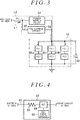
FIG. 3 is a block diagram illustrating a drive circuit according to the first embodiment; -
FIG. 4 is a block diagram illustrating a pre-charge circuit according to the first embodiment; -
FIG. 5 is a graph illustrating an operating voltage range of a microcomputer according to the first embodiment; -
FIG. 6 is a flowchart illustrating a procedure to be performed by the microcomputer according to the first embodiment; and -
FIG. 7 is a block diagram illustrating an ECU according to a second embodiment. - A vehicle control apparatus according to a first embodiment of the invention embodied as a control apparatus of an electric power steering system (hereinafter referred to as "EPS") is described below. As illustrated in
FIG. 1 , anEPS 10 includes asteering mechanism 20 that turns steered wheels based on a driver's steering operation, asteering assist mechanism 30 that assists the driver's steering operation, and an electronic control unit (ECU) 40 that controls actuation of the steering assistmechanism 30. - The
steering mechanism 20 includes asteering wheel 21 operated by a driver and a steeringshaft 22 that rotates integrally with thesteering wheel 21. The steeringshaft 22 includes acolumn shaft 22a connected to thesteering wheel 21, anintermediate shaft 22b connected to a lower end portion of thecolumn shaft 22a, and apinion shaft 22c connected to a lower end portion of theintermediate shaft 22b. A lower end portion of thepinion shaft 22c is meshed with a rack shaft 23 (more specifically, aportion 23a where a rack tooth is provided) extending in a direction intersecting thepinion shaft 22c. A rotary motion of the steeringshaft 22 is converted into a reciprocating linear motion of therack shaft 23 through meshing between thepinion shaft 22c and therack shaft 23. The reciprocating linear motion is transmitted to a right steeredwheel 26 and a left steeredwheel 26 each via a corresponding one oftie rods 25 that are coupled to respective ends of therack shaft 23. As a result, a steered angle θw of the steeredwheels 26 is changed. - The
steering assist mechanism 30 includes amotor 31 that is a source of a steering assist force (assist torque). A three-phase brushless motor may be employed as themotor 31, for example. Themotor 31 is coupled to thecolumn shaft 22a via areduction mechanism 32. Thereduction mechanism 32 reduces a speed of rotation of themotor 31 and transmits a rotary force of the reduced speed to thecolumn shaft 22a. Thus, a torque of themotor 31 is applied to the steeringshaft 22 as a steering assist force to assist a driver's steering operation. - The
ECU 40 obtains detection results of various sensors provided in the vehicle as information (state variables) indicating a driver's demand, a driving state, and a steering state and controls themotor 31 in accordance with the obtained various information. Examples of the various sensors include avehicle speed sensor 41, atorque sensor 42, and arotation angle sensor 43. Thevehicle speed sensor 41 detects a vehicle speed (driving speed of the vehicle) V. Thetorque sensor 42 is provided on thecolumn shaft 22a. Thetorque sensor 42 detects a steering torque τ applied to the steeringshaft 22. Therotation angle sensor 43 is provided on themotor 31. Therotation angle sensor 43 detects a rotation angle θm of themotor 31. - The
ECU 40 performs vector control of themotor 31 using the rotation angle θm of themotor 31 detected through therotation angle sensor 43. TheECU 40 performs assist control by calculating a target assist torque based on the steering torque τ and the vehicle speed V and supplying themotor 31 with driving power that causes the steering assistmechanism 30 to produce the calculated target assist torque. - The
ECU 40 is described in detail below. As illustrated inFIG. 2 , theECU 40 includes adrive circuit 51, apre-charge circuit 52, apower supply relay 53, and amicrocomputer 54. - The
microcomputer 54 is supplied with power from abattery 61 mounted in the vehicle. Thebattery 61 and themicrocomputer 54 are connected via apower supply line 62. Apower switch 63, such as an ignition switch, of the vehicle is provided on thepower supply line 62. Electrical continuity of thepower supply line 62 is switched on and off by operating thepower switch 63. Thepower switch 63 is operated to actuate a drive source (e.g., an engine) for driving the vehicle. When thepower switch 63 is turned on, power of thebattery 61 is supplied to themicrocomputer 54 via thepower supply line 62. - The
drive circuit 51 is also supplied with power from thebattery 61. Thebattery 61 and thedrive circuit 51 are connected via apower supply line 64. Thepower supply relay 53 is provided on thepower supply line 64. Thepower supply relay 53 switches on and off electrical continuity of thepower supply line 64 in accordance with a command from themicrocomputer 54. When thepower supply relay 53 is turned on, power of thebattery 61 is supplied to thedrive circuit 51 via thepower supply line 64. - A junction PI is provided on the
power supply line 64 between thebattery 61 and thepower supply relay 53. A junction P2 is provided on thepower supply line 64 between thepower supply relay 53 and thedrive circuit 51. The junction PI and the junction P2 are connected via apower supply line 65. Thepre-charge circuit 52 is provided on thepower supply line 65. Thepre-charge circuit 52 switches on and off electrical continuity of thepower supply line 65 in accordance with a command from themicrocomputer 54. When thepre-charge circuit 52 is turned on, power of thebattery 61 is supplied to the drive circuit 51via thepower supply line 65. Thedrive circuit 51 and themotor 31 are connected viafeeder paths 66 for three phases. Thefeeder paths 66 are constituted of bus bars or cables, for example. - A
voltage sensor 71 is provided on thepower supply line 62. Thevoltage sensor 71 detects a voltage Vig (IG voltage) on thepower supply line 62 as a power supply voltage of themicrocomputer 54. - Two
voltage sensors power supply line 64. Thevoltage sensor 72 is provided on thepower supply line 64 between thebattery 61 and thepower supply relay 53. Thevoltage sensor 73 is provided on thepower supply line 64 between thepower supply relay 53 and thedrive circuit 51. Thevoltage sensor 72 detects a voltage Vpig1 (a first PIG voltage) on thepower supply line 64 between thebattery 61 and thepower supply relay 53. Thevoltage sensor 73 detects a voltage Vpig2 (a second PIG voltage) on thepower supply line 64 between thepower supply relay 53 and thedrive circuit 51. Acurrent sensor 74 is provided on thefeeder paths 66. Thecurrent sensor 74 detects a current Im of each phase supplied from thedrive circuit 51 to themotor 31. - As illustrated in
FIG. 3 , thedrive circuit 51 is a pulse width modulation (PWM) inverter formed by connecting threelegs drive circuit 51 converts direct current (DC) power supplied from thebattery 61 into three-phase alternating current (AC) power such that the switching device (the FETs) of each of the three phases performs a switching operation based on a command signal Sc generated by themicrocomputer 54. The three-phase AC power generated by thedrive circuit 51 is supplied to themotor 31 via the feeder paths 66 (omitted fromFIG. 3 for clarity) for the three phases. - A
capacitor 82 for power supply stabilization is provided for thedrive circuit 51. Thecapacitor 82 is connected in parallel with the parallel-connected threelegs capacitor 82 stores electric charge. In case of shortage of power to be supplied to thedrive circuit 51 from thebattery 61, thecapacitor 82 discharges the stored charge to compensate for the power shortage. - As illustrated in
FIG. 4 , thepre-charge circuit 52 includes anFET drive circuit 83, anFET 84, and aresistor 85 for suppressing inrush current. TheFET 84 and theresistor 85 are provided on thepower supply line 65. TheFET 84 is on a drive circuit 51 (load) side, while theresistor 85 is on a battery 61 (power supply) side. TheFET drive circuit 83 drives theFET 84 in accordance with a command from themicrocomputer 54. As theFET 84 is turned on and off, electrical continuity of thepower supply line 65 is switched on and off. - As indicated by a long dashed short dashed line in
FIG. 3 , when the pre-charge circuit 52 (the FET 84) is turned on with thepower supply relay 53 off, power of thebattery 61 is supplied to thedrive circuit 51 through an electrical path L1 that includes (theresistor 85 and theFET 84 of) thepre-charge circuit 52. Power of thebattery 61 is supplied to thecapacitor 82 when each of the switching devices of thedrive circuit 51 is off. As a result, thecapacitor 82 is charged. As indicated by a dashed line inFIG. 3 , when thepower supply relay 53 is turned on with (theFET 84 of) thepre-charge circuit 52 off, power of thebattery 61 is supplied to thedrive circuit 51 through an electrical path L2 that includes thepower supply relay 53. - The
microcomputer 54 calculates a target assist torque to be produced by themotor 31 based on the steering torque τ detected through thetorque sensor 42 and the vehicle speed V detected through thevehicle speed sensor 41, and calculates a current command value in accordance with the calculated target assist torque. The current command value is a target value of current to be supplied to themotor 31 so that the target assist torque of an appropriate magnitude is produced in accordance with the steering torque τ and the vehicle speed V. Themicrocomputer 54 calculates the current command value to have an absolute value that increases as an absolute value of the steering torque τ increases and the vehicle speed V becomes lower. - The
microcomputer 54 generates the command signal Sc (PWM signal) for thedrive circuit 51 by performing current feedback control that causes an actual value of current supplied to themotor 31 to follow the current command value. The command signal Sc defines a duty ratio of each switching device of thedrive circuit 51. The duty ratio means a ratio of an on period of the switching device to a pulse cycle. Themicrocomputer 54 controls power supply to themotor 31 using the rotation angle θm of themotor 31 detected through therotation angle sensor 43. Electric current is supplied to themotor 31 in accordance with the command signal Sc through thedrive circuit 51, causing themotor 31 to produce a torque in accordance with the current command value. - As indicated in a graph of
FIG. 5 , an operating voltage range 8V is set for themicrocomputer 54. The operating voltage range 8V is a range of voltage within which themicrocomputer 54 is guaranteed to operate in specifications. Themicrocomputer 54 starts operating when the voltage Vig (power supply voltage) detected through thevoltage sensor 71 has entered the operating voltage range δV Themicrocomputer 54 does not operate when the voltage Vig detected through thevoltage sensor 71 is above the operating voltage range δV - The operating voltage range 8V is set as a range from a lower limit voltage VLL to an upper limit voltage VUL, both inclusive. The lower limit voltage VLL is set to a value larger than a first voltage determination threshold Vth1. The first voltage determination threshold Vth1 is a voltage used by the
microcomputer 54 as a reference when recognizing that thepower switch 63 is turned off. The first voltage determination threshold Vth1 is set to 0 (zero) or a value close to 0. - The
microcomputer 54 recognizes that thepower switch 63 is turned off when a state where the voltage Vig detected through thevoltage sensor 71 is below the first voltage determination threshold Vth1 continues for a preset period T1. The reason for this is to reduce false determination that would otherwise be made by themicrocomputer 54 by falsely determining that, when the voltage Vig instantaneously drops below the first voltage determination threshold Vth1, thepower switch 63 is turned off based on the drop. - When power is turned on or, more specifically, when the voltage Vig detected through the
voltage sensor 71 has entered the operating voltage range 8V, themicrocomputer 54 starts what is generally referred to as initial check. The initial check is a check (inspection) prior to starting power supply to themotor 31 and is inspection for anomalies in parts for driving themotor 31, such as thepower supply relay 53, windings of themotor 31, and thedrive circuit 51. - A procedure to be performed by the
microcomputer 54 when power is turned on is described below. Each of thepre-charge circuit 52, thepower supply relay 53, and (the switching devices of) thedrive circuit 51 is in its off state. - As illustrated in a flowchart of
FIG. 6 , when the voltage Vig (IG voltage) detected through thevoltage sensor 71 has entered the operating voltage range 8V from outside the operating voltage range 8V (step S101), themicrocomputer 54 determines whether a preset period T2 has elapsed from when the voltage Vig has entered the operating voltage range 8V (step S102). Themicrocomputer 54 measures a period of time elapsed from when the voltage Vig has entered the operating voltage range 8V through acounter 54a. The preset period T2 is obtained by experiment or simulation. The preset period T2 is set with reference to a period of time over which the voltage Vig, with thepower switch 63 off, decreases from the upper limit voltage VUL of the operating voltage range δV to a value (e.g., 0 V or a value close to 0 V) below the operating voltage range δV. In the first embodiment, as illustrated in the graph ofFIG. 5 , the preset period T2 is set so as to elapse concurrently at the time (time t5) when the preset period T1 for use in determining whether thepower switch 63 is off elapses. When lapse of the preset period T2 is measured through thecounter 54a, themicrocomputer 54 clears (resets) thecounter 54a. - When it is not determined that the preset period T2 has elapsed from when the voltage Vig has entered the operating voltage range δV (step S102: NO), the
microcomputer 54 completes processing without carrying out the initial check. When it is determined that the preset period T2 has elapsed from when the voltage Vig has entered the operating voltage range 8V (step S102: YES), themicrocomputer 54 starts the initial check (step S103). - The
microcomputer 54 starts the initial check such that themicrocomputer 54 turns on thepre-charge circuit 52 when a difference between the voltage Vpig1 detected through thevoltage sensor 72 and the voltage Vpig2 detected through thevoltage sensor 73 is above a second voltage determination threshold Vth2 as indicated by an expression (A1) below. This causes DC power of thebattery 61 to be supplied to thedrive circuit 51 via thepre-charge circuit 52. Because each switching device of thedrive circuit 51 is held in its off state at this time, the DC power of thebattery 61 is supplied tocapacitor 82. Thecapacitor 82 is supplied with the DC power from thebattery 61 and accordingly charged. - The second voltage determination threshold Vth2 is set with reference to the difference (=|Vpig1 - Vpig2|) in voltage across the
power supply relay 53, which does not cause inrush current into thecapacitor 82 from thebattery 61 when thepower supply relay 53 is turned on.
- When the difference between the voltage Vpig1 detected through the
voltage sensor 72 and the voltage Vpig2 detected through thevoltage sensor 73 drops to or below the second voltage determination threshold Vth2 as indicated by an expression (A2) below, themicrocomputer 54 recognizes that charging of thecapacitor 82 is completed, and accordingly turns off thepre-charge circuit 52 and then turns on thepower supply relay 53. This causes power of thebattery 61 to be supplied to thedrive circuit 51. At this time, inrush current into thecapacitor 82 from thebattery 61 does not occur because charging of thecapacitor 82 is completed.
- Before turning on the
power supply relay 53, themicrocomputer 54 may carry out diagnostics of determining whether there is sticking in thepower supply relay 53 as a part of the initial check. When there is sticking in thepower supply relay 53, the voltage Vpig2 on the load side of thepower supply relay 53 is brought to the same level as the voltage (power supply voltage) of thebattery 61 via thepower supply relay 53. Hence, whether there is sticking on thepower supply relay 53 is detectable based on the voltage Vpig2 on the load side of thepower supply relay 53. Themicrocomputer 54 turns on thepower supply relay 53 when no anomaly is detected in thepower supply relay 53. - After tuning on the
power supply relay 53, themicrocomputer 54 carries out diagnostics of parts (e.g., the drive circuit 51) other than thepower supply relay 53 and then completes processing. After the initial check is completed normally, themicrocomputer 54 performs assist control that supplies power to themotor 31 in accordance with a steering state. - Operations performed by the
microcomputer 54 when power is turned on through the procedure illustrated in the flowchart ofFIG. 6 are described below. - A situation where a voltage drop of the
battery 61, for example, makes it difficult to supply required power to an electrical load, such as a starter for starting an engine, may occur. Under such a situation, what is generally referred to as jump start that starts the engine of a disabled vehicle by supplying power from a battery mounted in a rescue vehicle may be performed. - To perform jump start, the
battery 61 of the disabled vehicle is connected to the battery of the rescue vehicle. As a result, as indicated by a point PV1 in the graph ofFIG. 5 , the voltage Vig detected through thevoltage sensor 71, i.e., the power supply voltage of themicrocomputer 54, may be held in an overvoltage condition where the power supply voltage is above the operating voltage range 8V (time t1). For example, when thepower switch 63 is turned off under the overvoltage condition indicated by the point PV1 after the engine is started by jump start, the voltage Vig changes as follows. - Electrical continuity of the
power supply line 62 between thebattery 61 and themicrocomputer 54 is shut off by turning off thepower switch 63. As indicated by a characteristic line LV in the graph ofFIG. 5 , the voltage Vig (power supply voltage) gradually decreases to the upper limit voltage VUL of the operating voltage range 8V (time t2). Thereafter, the voltage Vig further decreases to the lower limit voltage VLL (time t3). The voltage Vig subsequently continues decreasing and eventually reaches the first voltage determination threshold Vth1 (time t4). - As described above, when the
power switch 63 is turned off under the overvoltage condition, the voltage Vig stays within the operating voltage range 8V by which an initial check start condition is satisfied, although for only a slight period of time (period from time t2 to time t3). - The
microcomputer 54 recognizes that thepower switch 63 is turned off when the preset period T1 has elapsed (time t5) from when the voltage Vig has dropped below the first voltage determination threshold Vth1. There is some time lag from when thepower switch 63 is actually turned off at time t1 to when themicrocomputer 54 actually recognizes that thepower switch 63 is turned off at time t5. Themicrocomputer 54 recognizes that the voltage Vig has entered the operating voltage range 8V earlier than recognizing that thepower switch 63 is turned off. Themicrocomputer 54 then accordingly starts the initial check immediately. However, in this case, the following disadvantage may arise. - The
microcomputer 54 carries out the initial check such that themicrocomputer 54 turns on thepre-charge circuit 52 and, when triggered by completion of charging of thecapacitor 82, turns on thepower supply relay 53. This causes power from thebattery 61 to be supplied to a circuit downstream of thepower supply relay 53. At this time, because thebattery 61 is connected to the battery of the rescue vehicle and therefore held in the overvoltage condition, a voltage above durable power of thepre-charge circuit 52 may be applied to thepre-charge circuit 52, more specifically, to theFET 84 of thepre-charge circuit 52. - However, according to the first embodiment, when the preset period T2 has elapsed (step S102 of
FIG. 6 : YES) from when the voltage Vig has entered the operating voltage range 8V from the outside the operating voltage range 8V, themicrocomputer 54 starts the initial check. - The preset period T2 is set with reference to the period of time over which the voltage Vig decreases from the upper limit voltage VUL of the operating voltage range δV to a value below the operating voltage range 8V, with the
power switch 63 off. Hence, as indicated by the characteristic line LV in the graph ofFIG. 5 , in a situation where thepower switch 63 is turned off under the overvoltage condition where the voltage Vig is above the operating voltage range δV, when the preset period T2 has elapses (time t5) from the time when the voltage Vig has decreased to the upper limit voltage VUL of the operating voltage range 8V (time t2), the voltage Vig has decreased to a value below the operating voltage range δV. According to the first embodiment, the time when themicrocomputer 54 recognizes that thepower switch 63 is turned off is also the time when the preset period T2 has elapsed from the time when the voltage Vig has decreased to the upper limit voltage VUL of the operating voltage range δV. - Because the
microcomputer 54 does not determine that the voltage Vig has entered the operating voltage range 8V, themicrocomputer 54 does not carry out the initial check. Furthermore, according to the first embodiment, themicrocomputer 54 also recognizes that thepower switch 63 is turned off. This also causes themicrocomputer 54 not to carry out the initial check. Because theFET 84 of thepre-charge circuit 52 is not turned on, application of an overvoltage above the operating voltage range δV to theFET 84 of thepre-charge circuit 52 does not occur. This allows protecting theFET 84, which leads to protecting thepre-charge circuit 52. - The
microcomputer 54 performs the procedure illustrated in the flowchart ofFIG. 6 also when power is turned on under a normal condition. More specifically, themicrocomputer 54 starts the initial check when the voltage Vig has entered the operating voltage range δV from the outside the operating voltage range δV (in this example, a value below the operating voltage range δV) (step S101) and the preset period T2 has elapsed (step S102: YES). If power is turned on under a normal condition, even after the preset period T2 has elapsed from when the voltage Vig has entered the operating voltage range δV, the voltage Vig is basically held within the operating voltage range δV. - The first embodiment provides the following advantages. (1) The
microcomputer 54 starts the initial check after the preset period T2 has elapsed from when the voltage Vig detected through thevoltage sensor 71 has entered the operating voltage range δV. Hence, even when thepower switch 63 is turned off under an overvoltage condition where the voltage Vig is above the operating voltage range δV, which may occur when jump start is performed, and, as a result, the voltage Vig temporarily (instantaneously) enters the operating voltage range δV, themicrocomputer 54 does not start the initial check immediately. Because an overvoltage is not applied to thepre-charge circuit 52, occurrence of an anomaly in thepre-charge circuit 52, more specifically, in theFET 84 that is an element of thepre-charge circuit 52, can be reduced. Protecting thepre-charge circuit 52 from overvoltage is thus achieved. - (2) Meanwhile, a high power durable FET may be employed as the
FET 84 of thepre-charge circuit 52. However, such a high power durable FET is typically expensive and larger in size. According to the first embodiment, protecting thepre-charge circuit 52 is achieved by devising a condition to turn on thepre-charge circuit 52 rather than by changing the configuration of theECU 40 or by adding a new element to theECU 40. This leads to reduction in increases in product cost and product size of theECU 40. - A vehicle control apparatus according to a second embodiment is described below. As illustrated in
FIG. 7 , anECU 90 controls power supply to amotor 91 including two winding systems, a first winding system and a second winding system. Themotor 91 includes arotor 91a, and a first windinggroup 91b and a second windinggroup 91c wound around stators (not illustrated). The first windinggroup 91b includes a U-phase coil, a V-phase coil, and a W-phase coil. The second windinggroup 91c includes a U-phase coil, a V-phase coil, and a W-phase coil as well. - The
motor 91 includes tworotation angle sensors rotation angle sensors motor 91. Twotorque sensors column shaft 22a, for example. Thetorque sensors shaft 22. - The
ECU 90 controls power supply to the first windinggroup 91b and the second windinggroup 91c individually on a per-winding-system basis. TheECU 90 includes afirst control unit 40a that controls power supply to the first windinggroup 91b and asecond control unit 40b that controls power supply to the second windinggroup 91c. Each of thefirst control unit 40a and thesecond control unit 40b is basically identical in configuration to theECU 40 illustrated inFIG. 2 . Thefirst control unit 40a controls power supply to the first windinggroup 91b based on the steering torques τ1, the vehicle speed V, and the rotation angle θm1 of themotor 91. Thesecond control unit 40b controls power supply to the second windinggroup 91c based on the steering torques τ2, the vehicle speed V, and the rotation angle θm2 of themotor 91. - When power is turned on, the
ECU 90 carries out the initial check individually on a per-winding-system basis. When power is turned on, thefirst control unit 40a starts the initial check of the first winding system to which thefirst control unit 40a belongs by performing the procedure illustrated in the flowchart ofFIG. 6 . When power is turned on, thesecond control unit 40b starts the initial check of the second winding system to which thesecond control unit 40b belongs by performing the procedure illustrated in the flowchart ofFIG. 6 as well. - The
ECU 90 may control a motor including three or more winding systems each including a winding group. Also in this case, theECU 90 controls power supply to the winding groups of the three or more winding systems independently. In this case, theECU 90 may be configured to include individual control units corresponding to each of the winding systems. - According to the second embodiment, the following advantage is obtained in addition to the advantages (1) and (2) of the first embodiment. (3) When an anomaly occurs in any one of the two winding systems, power is supplied to the winding group of the remaining normal winding system to continue driving the
motor 91. - The first and second embodiments may be modified as follows. In the first and second embodiments, a battery of an appropriate voltage, e.g., 12 V, 24 V, or 36 V, may be employed as the
battery 61 in accordance with specifications of the vehicle. - The first and second embodiments describe an example in which an EPS that transmits a torque of the motor (31, 91) to (the
column shaft 22a of) thesteering shaft 22 is employed as theEPS 10. Alternatively, an EPS that transmits a torque of the motor (31, 91) to therack shaft 23 may be employed as theEPS 10. - In the first and second embodiments, the vehicle control apparatus is embodied as the ECU (40, 90) that controls the motor (31, 91) of the
EPS 10. Alternatively, the vehicle control apparatus may be embodied as a control apparatus for a steer-by-wire steering system in which power transmission between thesteering wheel 21 and the steeredwheels - In the first and second embodiments, the vehicle control apparatus is embodied as the ECU (40, 90) that controls the motor (31, 91) of the
EPS 10. Alternatively, the vehicle control apparatus may be embodied as a control apparatus of a motor used in vehicle-mounted equipment other than a steering system, such as theEPS 10.
Claims (6)
- A vehicle control apparatus comprising:a drive circuit that supplies driving power based on a power supply voltage to a motor;a capacitor for power supply stabilization, the capacitor being connected in parallel with the drive circuit;a control circuit that controls an operation of the drive circuit;a power switch that opens and closes a first power supply path that connects between the control circuit and a power supply;a power supply relay that opens and closes a second power supply path that connects between the drive circuit and the power supply; anda pre-charge circuit that opens and closes a third power supply path that connects between the drive circuit and the power supply, wherein after a lapse of a first preset period from when a voltage supplied through the first power supply path has entered an operating voltage range due to turning on of the power switch, the control circuit starts charging the capacitor by turning on the pre-charge circuit and, when the charging of the capacitor is completed, turns on the power supply relay.
- The vehicle control apparatus according to claim 1, wherein the first preset period is set with reference to a period of time over which the voltage on the first power supply path decreases from an upper limit voltage of the operating voltage range to a value below the operating voltage range, with the power switch off.
- The vehicle control apparatus according to claim 1 or 2, wherein
the control circuit recognizes that the power switch is turned off when a second preset period has elapsed from when the voltage on the first power supply path has dropped below a first voltage determination threshold that is set to a value below the operating voltage range, and
the first preset period is set so as to elapse concurrently when the second preset period elapses. - The vehicle control apparatus according to any one of claims 1 to 3, wherein the control circuit determines that the charging of the capacitor is completed when a difference in voltage across the power switch is equal to or below a second voltage determination threshold that is set with reference to a value that does not cause inrush current into the capacitor when the power supply relay is turned on.
- The vehicle control apparatus according to any one of claims 1 to 4, wherein when the charging of the capacitor is completed, the control circuit carries out diagnostics of the power supply relay as a part of an initial check that is a check prior to starting power supply to the motor, and turns on the power supply relay when a result of the diagnostics indicates no anomaly.
- The vehicle control apparatus according to any one of claims 1 to 5, wherein the motor produces a torque to be applied to a steering mechanism of a vehicle.
Applications Claiming Priority (1)
| Application Number | Priority Date | Filing Date | Title |
|---|---|---|---|
| JP2018164639A JP7172306B2 (en) | 2018-09-03 | 2018-09-03 | vehicle controller |
Publications (2)
| Publication Number | Publication Date |
|---|---|
| EP3616970A1 true EP3616970A1 (en) | 2020-03-04 |
| EP3616970B1 EP3616970B1 (en) | 2023-10-18 |
Family
ID=67810429
Family Applications (1)
| Application Number | Title | Priority Date | Filing Date |
|---|---|---|---|
| EP19194537.7A Active EP3616970B1 (en) | 2018-09-03 | 2019-08-30 | Vehicle control apparatus |
Country Status (4)
| Country | Link |
|---|---|
| US (1) | US11453435B2 (en) |
| EP (1) | EP3616970B1 (en) |
| JP (1) | JP7172306B2 (en) |
| CN (1) | CN110871840B (en) |
Families Citing this family (5)
| Publication number | Priority date | Publication date | Assignee | Title |
|---|---|---|---|---|
| JP7474181B2 (en) * | 2020-11-06 | 2024-04-24 | 株式会社ミツバ | Motor control device and motor control method |
| CN116802085A (en) * | 2021-01-29 | 2023-09-22 | 日立安斯泰莫株式会社 | Electronic control devices for vehicle-mounted equipment |
| US11303122B1 (en) * | 2021-07-06 | 2022-04-12 | Shenzhen Caross Co., Ltd | Jumper cable device and jump start system |
| US12489291B2 (en) | 2021-08-06 | 2025-12-02 | Shenzhen Caross Co., Ltd | Jumper cable device and jump start system |
| CN115384328B (en) * | 2022-09-06 | 2024-09-13 | 中国第一汽车股份有限公司 | Electric automobile charging control method and device |
Citations (4)
| Publication number | Priority date | Publication date | Assignee | Title |
|---|---|---|---|---|
| JPS619332B2 (en) | 1981-08-04 | 1986-03-22 | Toray Industries | |
| GB2392990A (en) * | 2002-09-11 | 2004-03-17 | Visteon Global Tech Inc | Method for detecting failure of a relay |
| JP2007276706A (en) | 2006-04-10 | 2007-10-25 | Nsk Ltd | Electric power steering control device |
| JP2010193663A (en) * | 2009-02-19 | 2010-09-02 | Nsk Ltd | Motor control device |
Family Cites Families (10)
| Publication number | Priority date | Publication date | Assignee | Title |
|---|---|---|---|---|
| JP4174038B2 (en) | 2004-07-06 | 2008-10-29 | 株式会社ケーヒン | Starter drive control circuit |
| JP4545007B2 (en) | 2005-02-02 | 2010-09-15 | シーケーディ株式会社 | Servo motor control device |
| JP4635664B2 (en) | 2005-03-16 | 2011-02-23 | トヨタ自動車株式会社 | Power supply system and control method thereof |
| JP2008059516A (en) | 2006-09-04 | 2008-03-13 | Nec Tokin Corp | Active radio tag |
| JP5407106B2 (en) | 2006-12-20 | 2014-02-05 | 日本精工株式会社 | Motor drive control device and electric power steering device using the same |
| JP5444992B2 (en) * | 2009-09-24 | 2014-03-19 | 株式会社ジェイテクト | Electric power steering device |
| DE102010041275B4 (en) * | 2010-09-23 | 2019-11-28 | Robert Bosch Gmbh | Procedure for checking the proper functioning of a current sensor |
| EP3067251B1 (en) | 2013-11-08 | 2019-01-02 | Mitsubishi Electric Corporation | Electric power steering control device and electric power steering control method |
| JP6386315B2 (en) * | 2014-09-19 | 2018-09-05 | 日立オートモティブシステムズ株式会社 | Motor drive device |
| JP6683152B2 (en) * | 2017-02-23 | 2020-04-15 | 株式会社デンソー | Abnormality diagnosis device |
-
2018
- 2018-09-03 JP JP2018164639A patent/JP7172306B2/en active Active
-
2019
- 2019-08-28 US US16/553,792 patent/US11453435B2/en active Active
- 2019-08-30 EP EP19194537.7A patent/EP3616970B1/en active Active
- 2019-09-02 CN CN201910822438.0A patent/CN110871840B/en active Active
Patent Citations (4)
| Publication number | Priority date | Publication date | Assignee | Title |
|---|---|---|---|---|
| JPS619332B2 (en) | 1981-08-04 | 1986-03-22 | Toray Industries | |
| GB2392990A (en) * | 2002-09-11 | 2004-03-17 | Visteon Global Tech Inc | Method for detecting failure of a relay |
| JP2007276706A (en) | 2006-04-10 | 2007-10-25 | Nsk Ltd | Electric power steering control device |
| JP2010193663A (en) * | 2009-02-19 | 2010-09-02 | Nsk Ltd | Motor control device |
Also Published As
| Publication number | Publication date |
|---|---|
| CN110871840A (en) | 2020-03-10 |
| US11453435B2 (en) | 2022-09-27 |
| CN110871840B (en) | 2023-06-20 |
| JP7172306B2 (en) | 2022-11-16 |
| US20200070874A1 (en) | 2020-03-05 |
| EP3616970B1 (en) | 2023-10-18 |
| JP2020039200A (en) | 2020-03-12 |
Similar Documents
| Publication | Publication Date | Title |
|---|---|---|
| EP3616970B1 (en) | Vehicle control apparatus | |
| EP2826659B1 (en) | Onboard motor controller | |
| US8680808B2 (en) | Motor drive apparatus and electric power steering apparatus using the same | |
| JP5653516B2 (en) | Motor control device | |
| EP2746136B1 (en) | Electrical power steering apparatus | |
| US20140055059A1 (en) | Motor driving device and electric power steering apparatus including motor driving device | |
| US9126620B2 (en) | Electric power steering system | |
| EP1787893A1 (en) | Electric power steering apparatus | |
| JP2003089360A (en) | Electric power steering device | |
| US9407190B2 (en) | Electric power steering apparatus | |
| EP2621788B1 (en) | Electric power steering apparatus | |
| US20120019181A1 (en) | Power converter for rotating electric machine | |
| US20140229066A1 (en) | Electronic control device for electric power steering apparatus | |
| EP3597508A2 (en) | Motor controller | |
| JP2011036048A (en) | Electric vehicle | |
| US7164362B2 (en) | Apparatus for driving a brushless motor | |
| EP3444166A1 (en) | Power steering system | |
| US20080217095A1 (en) | Limiting Device for Limiting Relay Welding and Motor Driving Apparatus | |
| JP2014172491A (en) | Electric power steering device | |
| EP4143964B1 (en) | Motor control device and motor control method | |
| JP5157511B2 (en) | Electric power steering device | |
| JP2014133433A (en) | Electric power steering device |
Legal Events
| Date | Code | Title | Description |
|---|---|---|---|
| PUAI | Public reference made under article 153(3) epc to a published international application that has entered the european phase |
Free format text: ORIGINAL CODE: 0009012 |
|
| STAA | Information on the status of an ep patent application or granted ep patent |
Free format text: STATUS: THE APPLICATION HAS BEEN PUBLISHED |
|
| AK | Designated contracting states |
Kind code of ref document: A1 Designated state(s): AL AT BE BG CH CY CZ DE DK EE ES FI FR GB GR HR HU IE IS IT LI LT LU LV MC MK MT NL NO PL PT RO RS SE SI SK SM TR |
|
| AX | Request for extension of the european patent |
Extension state: BA ME |
|
| STAA | Information on the status of an ep patent application or granted ep patent |
Free format text: STATUS: REQUEST FOR EXAMINATION WAS MADE |
|
| 17P | Request for examination filed |
Effective date: 20200625 |
|
| RBV | Designated contracting states (corrected) |
Designated state(s): AL AT BE BG CH CY CZ DE DK EE ES FI FR GB GR HR HU IE IS IT LI LT LU LV MC MK MT NL NO PL PT RO RS SE SI SK SM TR |
|
| STAA | Information on the status of an ep patent application or granted ep patent |
Free format text: STATUS: EXAMINATION IS IN PROGRESS |
|
| 17Q | First examination report despatched |
Effective date: 20210714 |
|
| RAP3 | Party data changed (applicant data changed or rights of an application transferred) |
Owner name: JTEKT CORPORATION |
|
| GRAP | Despatch of communication of intention to grant a patent |
Free format text: ORIGINAL CODE: EPIDOSNIGR1 |
|
| STAA | Information on the status of an ep patent application or granted ep patent |
Free format text: STATUS: GRANT OF PATENT IS INTENDED |
|
| INTG | Intention to grant announced |
Effective date: 20221208 |
|
| GRAJ | Information related to disapproval of communication of intention to grant by the applicant or resumption of examination proceedings by the epo deleted |
Free format text: ORIGINAL CODE: EPIDOSDIGR1 |
|
| STAA | Information on the status of an ep patent application or granted ep patent |
Free format text: STATUS: EXAMINATION IS IN PROGRESS |
|
| INTC | Intention to grant announced (deleted) | ||
| GRAP | Despatch of communication of intention to grant a patent |
Free format text: ORIGINAL CODE: EPIDOSNIGR1 |
|
| STAA | Information on the status of an ep patent application or granted ep patent |
Free format text: STATUS: GRANT OF PATENT IS INTENDED |
|
| INTG | Intention to grant announced |
Effective date: 20230508 |
|
| RIN1 | Information on inventor provided before grant (corrected) |
Inventor name: FUJI, MASASHI Inventor name: MIKAMO, SATORU Inventor name: NIWA, TOMOHIRO |
|
| GRAS | Grant fee paid |
Free format text: ORIGINAL CODE: EPIDOSNIGR3 |
|
| GRAA | (expected) grant |
Free format text: ORIGINAL CODE: 0009210 |
|
| STAA | Information on the status of an ep patent application or granted ep patent |
Free format text: STATUS: THE PATENT HAS BEEN GRANTED |
|
| AK | Designated contracting states |
Kind code of ref document: B1 Designated state(s): AL AT BE BG CH CY CZ DE DK EE ES FI FR GB GR HR HU IE IS IT LI LT LU LV MC MK MT NL NO PL PT RO RS SE SI SK SM TR |
|
| REG | Reference to a national code |
Ref country code: GB Ref legal event code: FG4D |
|
| REG | Reference to a national code |
Ref country code: CH Ref legal event code: EP |
|
| REG | Reference to a national code |
Ref country code: IE Ref legal event code: FG4D |
|
| REG | Reference to a national code |
Ref country code: DE Ref legal event code: R096 Ref document number: 602019039488 Country of ref document: DE |
|
| REG | Reference to a national code |
Ref country code: LT Ref legal event code: MG9D |
|
| REG | Reference to a national code |
Ref country code: NL Ref legal event code: MP Effective date: 20231018 |
|
| REG | Reference to a national code |
Ref country code: AT Ref legal event code: MK05 Ref document number: 1622143 Country of ref document: AT Kind code of ref document: T Effective date: 20231018 |
|
| PG25 | Lapsed in a contracting state [announced via postgrant information from national office to epo] |
Ref country code: NL Free format text: LAPSE BECAUSE OF FAILURE TO SUBMIT A TRANSLATION OF THE DESCRIPTION OR TO PAY THE FEE WITHIN THE PRESCRIBED TIME-LIMIT Effective date: 20231018 |
|
| PG25 | Lapsed in a contracting state [announced via postgrant information from national office to epo] |
Ref country code: GR Free format text: LAPSE BECAUSE OF FAILURE TO SUBMIT A TRANSLATION OF THE DESCRIPTION OR TO PAY THE FEE WITHIN THE PRESCRIBED TIME-LIMIT Effective date: 20240119 |
|
| PG25 | Lapsed in a contracting state [announced via postgrant information from national office to epo] |
Ref country code: IS Free format text: LAPSE BECAUSE OF FAILURE TO SUBMIT A TRANSLATION OF THE DESCRIPTION OR TO PAY THE FEE WITHIN THE PRESCRIBED TIME-LIMIT Effective date: 20240218 |
|
| PG25 | Lapsed in a contracting state [announced via postgrant information from national office to epo] |
Ref country code: LT Free format text: LAPSE BECAUSE OF FAILURE TO SUBMIT A TRANSLATION OF THE DESCRIPTION OR TO PAY THE FEE WITHIN THE PRESCRIBED TIME-LIMIT Effective date: 20231018 |
|
| PG25 | Lapsed in a contracting state [announced via postgrant information from national office to epo] |
Ref country code: AT Free format text: LAPSE BECAUSE OF FAILURE TO SUBMIT A TRANSLATION OF THE DESCRIPTION OR TO PAY THE FEE WITHIN THE PRESCRIBED TIME-LIMIT Effective date: 20231018 |
|
| PG25 | Lapsed in a contracting state [announced via postgrant information from national office to epo] |
Ref country code: ES Free format text: LAPSE BECAUSE OF FAILURE TO SUBMIT A TRANSLATION OF THE DESCRIPTION OR TO PAY THE FEE WITHIN THE PRESCRIBED TIME-LIMIT Effective date: 20231018 |
|
| PG25 | Lapsed in a contracting state [announced via postgrant information from national office to epo] |
Ref country code: LT Free format text: LAPSE BECAUSE OF FAILURE TO SUBMIT A TRANSLATION OF THE DESCRIPTION OR TO PAY THE FEE WITHIN THE PRESCRIBED TIME-LIMIT Effective date: 20231018 Ref country code: IS Free format text: LAPSE BECAUSE OF FAILURE TO SUBMIT A TRANSLATION OF THE DESCRIPTION OR TO PAY THE FEE WITHIN THE PRESCRIBED TIME-LIMIT Effective date: 20240218 Ref country code: GR Free format text: LAPSE BECAUSE OF FAILURE TO SUBMIT A TRANSLATION OF THE DESCRIPTION OR TO PAY THE FEE WITHIN THE PRESCRIBED TIME-LIMIT Effective date: 20240119 Ref country code: ES Free format text: LAPSE BECAUSE OF FAILURE TO SUBMIT A TRANSLATION OF THE DESCRIPTION OR TO PAY THE FEE WITHIN THE PRESCRIBED TIME-LIMIT Effective date: 20231018 Ref country code: BG Free format text: LAPSE BECAUSE OF FAILURE TO SUBMIT A TRANSLATION OF THE DESCRIPTION OR TO PAY THE FEE WITHIN THE PRESCRIBED TIME-LIMIT Effective date: 20240118 Ref country code: AT Free format text: LAPSE BECAUSE OF FAILURE TO SUBMIT A TRANSLATION OF THE DESCRIPTION OR TO PAY THE FEE WITHIN THE PRESCRIBED TIME-LIMIT Effective date: 20231018 Ref country code: PT Free format text: LAPSE BECAUSE OF FAILURE TO SUBMIT A TRANSLATION OF THE DESCRIPTION OR TO PAY THE FEE WITHIN THE PRESCRIBED TIME-LIMIT Effective date: 20240219 |
|
| PG25 | Lapsed in a contracting state [announced via postgrant information from national office to epo] |
Ref country code: SE Free format text: LAPSE BECAUSE OF FAILURE TO SUBMIT A TRANSLATION OF THE DESCRIPTION OR TO PAY THE FEE WITHIN THE PRESCRIBED TIME-LIMIT Effective date: 20231018 Ref country code: RS Free format text: LAPSE BECAUSE OF FAILURE TO SUBMIT A TRANSLATION OF THE DESCRIPTION OR TO PAY THE FEE WITHIN THE PRESCRIBED TIME-LIMIT Effective date: 20231018 Ref country code: PL Free format text: LAPSE BECAUSE OF FAILURE TO SUBMIT A TRANSLATION OF THE DESCRIPTION OR TO PAY THE FEE WITHIN THE PRESCRIBED TIME-LIMIT Effective date: 20231018 Ref country code: NO Free format text: LAPSE BECAUSE OF FAILURE TO SUBMIT A TRANSLATION OF THE DESCRIPTION OR TO PAY THE FEE WITHIN THE PRESCRIBED TIME-LIMIT Effective date: 20240118 Ref country code: LV Free format text: LAPSE BECAUSE OF FAILURE TO SUBMIT A TRANSLATION OF THE DESCRIPTION OR TO PAY THE FEE WITHIN THE PRESCRIBED TIME-LIMIT Effective date: 20231018 Ref country code: HR Free format text: LAPSE BECAUSE OF FAILURE TO SUBMIT A TRANSLATION OF THE DESCRIPTION OR TO PAY THE FEE WITHIN THE PRESCRIBED TIME-LIMIT Effective date: 20231018 |
|
| PG25 | Lapsed in a contracting state [announced via postgrant information from national office to epo] |
Ref country code: DK Free format text: LAPSE BECAUSE OF FAILURE TO SUBMIT A TRANSLATION OF THE DESCRIPTION OR TO PAY THE FEE WITHIN THE PRESCRIBED TIME-LIMIT Effective date: 20231018 |
|
| REG | Reference to a national code |
Ref country code: DE Ref legal event code: R097 Ref document number: 602019039488 Country of ref document: DE |
|
| PG25 | Lapsed in a contracting state [announced via postgrant information from national office to epo] |
Ref country code: CZ Free format text: LAPSE BECAUSE OF FAILURE TO SUBMIT A TRANSLATION OF THE DESCRIPTION OR TO PAY THE FEE WITHIN THE PRESCRIBED TIME-LIMIT Effective date: 20231018 |
|
| PG25 | Lapsed in a contracting state [announced via postgrant information from national office to epo] |
Ref country code: SK Free format text: LAPSE BECAUSE OF FAILURE TO SUBMIT A TRANSLATION OF THE DESCRIPTION OR TO PAY THE FEE WITHIN THE PRESCRIBED TIME-LIMIT Effective date: 20231018 |
|
| PG25 | Lapsed in a contracting state [announced via postgrant information from national office to epo] |
Ref country code: SM Free format text: LAPSE BECAUSE OF FAILURE TO SUBMIT A TRANSLATION OF THE DESCRIPTION OR TO PAY THE FEE WITHIN THE PRESCRIBED TIME-LIMIT Effective date: 20231018 Ref country code: SK Free format text: LAPSE BECAUSE OF FAILURE TO SUBMIT A TRANSLATION OF THE DESCRIPTION OR TO PAY THE FEE WITHIN THE PRESCRIBED TIME-LIMIT Effective date: 20231018 Ref country code: RO Free format text: LAPSE BECAUSE OF FAILURE TO SUBMIT A TRANSLATION OF THE DESCRIPTION OR TO PAY THE FEE WITHIN THE PRESCRIBED TIME-LIMIT Effective date: 20231018 Ref country code: IT Free format text: LAPSE BECAUSE OF FAILURE TO SUBMIT A TRANSLATION OF THE DESCRIPTION OR TO PAY THE FEE WITHIN THE PRESCRIBED TIME-LIMIT Effective date: 20231018 Ref country code: EE Free format text: LAPSE BECAUSE OF FAILURE TO SUBMIT A TRANSLATION OF THE DESCRIPTION OR TO PAY THE FEE WITHIN THE PRESCRIBED TIME-LIMIT Effective date: 20231018 Ref country code: DK Free format text: LAPSE BECAUSE OF FAILURE TO SUBMIT A TRANSLATION OF THE DESCRIPTION OR TO PAY THE FEE WITHIN THE PRESCRIBED TIME-LIMIT Effective date: 20231018 Ref country code: CZ Free format text: LAPSE BECAUSE OF FAILURE TO SUBMIT A TRANSLATION OF THE DESCRIPTION OR TO PAY THE FEE WITHIN THE PRESCRIBED TIME-LIMIT Effective date: 20231018 |
|
| PLBE | No opposition filed within time limit |
Free format text: ORIGINAL CODE: 0009261 |
|
| STAA | Information on the status of an ep patent application or granted ep patent |
Free format text: STATUS: NO OPPOSITION FILED WITHIN TIME LIMIT |
|
| 26N | No opposition filed |
Effective date: 20240719 |
|
| PG25 | Lapsed in a contracting state [announced via postgrant information from national office to epo] |
Ref country code: SI Free format text: LAPSE BECAUSE OF FAILURE TO SUBMIT A TRANSLATION OF THE DESCRIPTION OR TO PAY THE FEE WITHIN THE PRESCRIBED TIME-LIMIT Effective date: 20231018 |
|
| PG25 | Lapsed in a contracting state [announced via postgrant information from national office to epo] |
Ref country code: SI Free format text: LAPSE BECAUSE OF FAILURE TO SUBMIT A TRANSLATION OF THE DESCRIPTION OR TO PAY THE FEE WITHIN THE PRESCRIBED TIME-LIMIT Effective date: 20231018 |
|
| REG | Reference to a national code |
Ref country code: CH Ref legal event code: PL |
|
| PG25 | Lapsed in a contracting state [announced via postgrant information from national office to epo] |
Ref country code: LU Free format text: LAPSE BECAUSE OF NON-PAYMENT OF DUE FEES Effective date: 20240830 |
|
| GBPC | Gb: european patent ceased through non-payment of renewal fee |
Effective date: 20240830 |
|
| PG25 | Lapsed in a contracting state [announced via postgrant information from national office to epo] |
Ref country code: CH Free format text: LAPSE BECAUSE OF NON-PAYMENT OF DUE FEES Effective date: 20240831 Ref country code: MC Free format text: LAPSE BECAUSE OF FAILURE TO SUBMIT A TRANSLATION OF THE DESCRIPTION OR TO PAY THE FEE WITHIN THE PRESCRIBED TIME-LIMIT Effective date: 20231018 |
|
| REG | Reference to a national code |
Ref country code: BE Ref legal event code: MM Effective date: 20240831 |
|
| PG25 | Lapsed in a contracting state [announced via postgrant information from national office to epo] |
Ref country code: GB Free format text: LAPSE BECAUSE OF NON-PAYMENT OF DUE FEES Effective date: 20240830 |
|
| PG25 | Lapsed in a contracting state [announced via postgrant information from national office to epo] |
Ref country code: BE Free format text: LAPSE BECAUSE OF NON-PAYMENT OF DUE FEES Effective date: 20240831 |
|
| PG25 | Lapsed in a contracting state [announced via postgrant information from national office to epo] |
Ref country code: IE Free format text: LAPSE BECAUSE OF NON-PAYMENT OF DUE FEES Effective date: 20240830 |
|
| PG25 | Lapsed in a contracting state [announced via postgrant information from national office to epo] |
Ref country code: FI Free format text: LAPSE BECAUSE OF FAILURE TO SUBMIT A TRANSLATION OF THE DESCRIPTION OR TO PAY THE FEE WITHIN THE PRESCRIBED TIME-LIMIT Effective date: 20231019 |
|
| PGFP | Annual fee paid to national office [announced via postgrant information from national office to epo] |
Ref country code: DE Payment date: 20250702 Year of fee payment: 7 |
|
| PGFP | Annual fee paid to national office [announced via postgrant information from national office to epo] |
Ref country code: FR Payment date: 20250703 Year of fee payment: 7 |
|
| PG25 | Lapsed in a contracting state [announced via postgrant information from national office to epo] |
Ref country code: CY Free format text: LAPSE BECAUSE OF FAILURE TO SUBMIT A TRANSLATION OF THE DESCRIPTION OR TO PAY THE FEE WITHIN THE PRESCRIBED TIME-LIMIT; INVALID AB INITIO Effective date: 20190830 |
|
| PG25 | Lapsed in a contracting state [announced via postgrant information from national office to epo] |
Ref country code: HU Free format text: LAPSE BECAUSE OF FAILURE TO SUBMIT A TRANSLATION OF THE DESCRIPTION OR TO PAY THE FEE WITHIN THE PRESCRIBED TIME-LIMIT; INVALID AB INITIO Effective date: 20190830 |