EP3616849A1 - Electric static discharge protection for power tools - Google Patents
Electric static discharge protection for power tools Download PDFInfo
- Publication number
- EP3616849A1 EP3616849A1 EP19179616.8A EP19179616A EP3616849A1 EP 3616849 A1 EP3616849 A1 EP 3616849A1 EP 19179616 A EP19179616 A EP 19179616A EP 3616849 A1 EP3616849 A1 EP 3616849A1
- Authority
- EP
- European Patent Office
- Prior art keywords
- resistor
- power tool
- capacitor
- power
- series
- Prior art date
- Legal status (The legal status is an assumption and is not a legal conclusion. Google has not performed a legal analysis and makes no representation as to the accuracy of the status listed.)
- Granted
Links
Images

Classifications
-
- B—PERFORMING OPERATIONS; TRANSPORTING
- B25—HAND TOOLS; PORTABLE POWER-DRIVEN TOOLS; MANIPULATORS
- B25F—COMBINATION OR MULTI-PURPOSE TOOLS NOT OTHERWISE PROVIDED FOR; DETAILS OR COMPONENTS OF PORTABLE POWER-DRIVEN TOOLS NOT PARTICULARLY RELATED TO THE OPERATIONS PERFORMED AND NOT OTHERWISE PROVIDED FOR
- B25F5/00—Details or components of portable power-driven tools not particularly related to the operations performed and not otherwise provided for
-
- H—ELECTRICITY
- H02—GENERATION; CONVERSION OR DISTRIBUTION OF ELECTRIC POWER
- H02K—DYNAMO-ELECTRIC MACHINES
- H02K11/00—Structural association of dynamo-electric machines with electric components or with devices for shielding, monitoring or protection
- H02K11/20—Structural association of dynamo-electric machines with electric components or with devices for shielding, monitoring or protection for measuring, monitoring, testing, protecting or switching
- H02K11/26—Devices for sensing voltage, or actuated thereby, e.g. overvoltage protection devices
-
- B—PERFORMING OPERATIONS; TRANSPORTING
- B23—MACHINE TOOLS; METAL-WORKING NOT OTHERWISE PROVIDED FOR
- B23D—PLANING; SLOTTING; SHEARING; BROACHING; SAWING; FILING; SCRAPING; LIKE OPERATIONS FOR WORKING METAL BY REMOVING MATERIAL, NOT OTHERWISE PROVIDED FOR
- B23D47/00—Sawing machines or sawing devices working with circular saw blades, characterised only by constructional features of particular parts
-
- B—PERFORMING OPERATIONS; TRANSPORTING
- B23—MACHINE TOOLS; METAL-WORKING NOT OTHERWISE PROVIDED FOR
- B23D—PLANING; SLOTTING; SHEARING; BROACHING; SAWING; FILING; SCRAPING; LIKE OPERATIONS FOR WORKING METAL BY REMOVING MATERIAL, NOT OTHERWISE PROVIDED FOR
- B23D59/00—Accessories specially designed for sawing machines or sawing devices
- B23D59/006—Accessories specially designed for sawing machines or sawing devices for removing or collecting chips
- B23D59/0064—Accessories specially designed for sawing machines or sawing devices for removing or collecting chips by suction
-
- B—PERFORMING OPERATIONS; TRANSPORTING
- B23—MACHINE TOOLS; METAL-WORKING NOT OTHERWISE PROVIDED FOR
- B23Q—DETAILS, COMPONENTS, OR ACCESSORIES FOR MACHINE TOOLS, e.g. ARRANGEMENTS FOR COPYING OR CONTROLLING; MACHINE TOOLS IN GENERAL CHARACTERISED BY THE CONSTRUCTION OF PARTICULAR DETAILS OR COMPONENTS; COMBINATIONS OR ASSOCIATIONS OF METAL-WORKING MACHINES, NOT DIRECTED TO A PARTICULAR RESULT
- B23Q11/00—Accessories fitted to machine tools for keeping tools or parts of the machine in good working condition or for cooling work; Safety devices specially combined with or arranged in, or specially adapted for use in connection with, machine tools
- B23Q11/04—Arrangements preventing overload of tools, e.g. restricting load
-
- H—ELECTRICITY
- H02—GENERATION; CONVERSION OR DISTRIBUTION OF ELECTRIC POWER
- H02H—EMERGENCY PROTECTIVE CIRCUIT ARRANGEMENTS
- H02H9/00—Emergency protective circuit arrangements for limiting excess current or voltage without disconnection
- H02H9/04—Emergency protective circuit arrangements for limiting excess current or voltage without disconnection responsive to excess voltage
- H02H9/041—Emergency protective circuit arrangements for limiting excess current or voltage without disconnection responsive to excess voltage using a short-circuiting device
-
- H—ELECTRICITY
- H02—GENERATION; CONVERSION OR DISTRIBUTION OF ELECTRIC POWER
- H02K—DYNAMO-ELECTRIC MACHINES
- H02K11/00—Structural association of dynamo-electric machines with electric components or with devices for shielding, monitoring or protection
- H02K11/30—Structural association with control circuits or drive circuits
- H02K11/33—Drive circuits, e.g. power electronics
-
- H—ELECTRICITY
- H02—GENERATION; CONVERSION OR DISTRIBUTION OF ELECTRIC POWER
- H02K—DYNAMO-ELECTRIC MACHINES
- H02K7/00—Arrangements for handling mechanical energy structurally associated with dynamo-electric machines, e.g. structural association with mechanical driving motors or auxiliary dynamo-electric machines
- H02K7/14—Structural association with mechanical loads, e.g. with hand-held machine tools or fans
- H02K7/145—Hand-held machine tool
-
- H—ELECTRICITY
- H10—SEMICONDUCTOR DEVICES; ELECTRIC SOLID-STATE DEVICES NOT OTHERWISE PROVIDED FOR
- H10W—GENERIC PACKAGES, INTERCONNECTIONS, CONNECTORS OR OTHER CONSTRUCTIONAL DETAILS OF DEVICES COVERED BY CLASS H10
- H10W42/00—Arrangements for protection of devices
- H10W42/60—Arrangements for protection of devices protecting against electrostatic charges or discharges, e.g. Faraday shields
-
- B—PERFORMING OPERATIONS; TRANSPORTING
- B23—MACHINE TOOLS; METAL-WORKING NOT OTHERWISE PROVIDED FOR
- B23D—PLANING; SLOTTING; SHEARING; BROACHING; SAWING; FILING; SCRAPING; LIKE OPERATIONS FOR WORKING METAL BY REMOVING MATERIAL, NOT OTHERWISE PROVIDED FOR
- B23D45/00—Sawing machines or sawing devices with circular saw blades or with friction saw discs
- B23D45/04—Sawing machines or sawing devices with circular saw blades or with friction saw discs with a circular saw blade or the stock carried by a pivoted lever
- B23D45/042—Sawing machines or sawing devices with circular saw blades or with friction saw discs with a circular saw blade or the stock carried by a pivoted lever with the saw blade carried by a pivoted lever
- B23D45/046—Sawing machines or sawing devices with circular saw blades or with friction saw discs with a circular saw blade or the stock carried by a pivoted lever with the saw blade carried by a pivoted lever the pivoted lever being mounted on a carriage
- B23D45/048—Sawing machines or sawing devices with circular saw blades or with friction saw discs with a circular saw blade or the stock carried by a pivoted lever with the saw blade carried by a pivoted lever the pivoted lever being mounted on a carriage the saw blade being adjustable according to angle of cut
-
- B—PERFORMING OPERATIONS; TRANSPORTING
- B23—MACHINE TOOLS; METAL-WORKING NOT OTHERWISE PROVIDED FOR
- B23D—PLANING; SLOTTING; SHEARING; BROACHING; SAWING; FILING; SCRAPING; LIKE OPERATIONS FOR WORKING METAL BY REMOVING MATERIAL, NOT OTHERWISE PROVIDED FOR
- B23D47/00—Sawing machines or sawing devices working with circular saw blades, characterised only by constructional features of particular parts
- B23D47/12—Sawing machines or sawing devices working with circular saw blades, characterised only by constructional features of particular parts of drives for circular saw blades
-
- H—ELECTRICITY
- H05—ELECTRIC TECHNIQUES NOT OTHERWISE PROVIDED FOR
- H05F—STATIC ELECTRICITY; NATURALLY-OCCURRING ELECTRICITY
- H05F3/00—Carrying-off electrostatic charges
- H05F3/02—Carrying-off electrostatic charges by means of earthing connections
Definitions
- the present invention relates to electric static discharge (ESD) protection system, and more particularly ESD protection systems for power tools.
- ESD electric static discharge
- a tool accessory such as a drill bit, a saw blade, sandpaper, etc.
- These accessories typically operate at a high rate of speed and rub against the material surfaces they intend to alter. This rubbing action can build up significant static charge on power tool surfaces relative to earth ground. Similarly, particles moving through air through the power tool or vacuum hose surfaces can also build significant static charge.
- This static charge is problematic because, if the charge is high enough, it can jump air gaps within the power tool and possibly damage electronic components within the power tool.
- Prior art solutions include using anti-static/conductive paints or coatings on vacuum hoses.
- paints and coatings may leave marks on surfaces when the vacuum hoses are dragged along such surfaces.
- a power tool such as miter saw 100, which has a base assembly 110, a table 120 rotatably disposed on the base assembly 110, a support section 130 rotatably connected to the table 120, at least one guide bar 140 fixedly attached to or sliding along the support section 130, and a saw assembly 150 sliding along or fixedly attached to the guide bar(s) 140. If multiple guide bars 140 are used, it is preferable to attach an end cap 141 to the ends of the guide bars 140 in order to ensure parallel alignment between the guide bars 140.
- the saw assembly 150 preferably has a saw support section 150SS fixedly attached to the guide bar(s) 140, a saw assembly housing 150H pivotably attached to the saw support section 150SS, a motor 150M supported by the saw assembly housing 150H, and a saw blade 150MB disposed on an arbor (not shown) and driven by motor 150M.
- saw assembly housing 150H (and thus saw blade 150MB) may be pivoted downwardly for cutting a workpiece W disposed on the table 120.
- Saw assembly housing 150H may have a handle (not shown) for sliding the saw assembly 150 relative to support section 130 and/or for downwardly pivoting the saw assembly housing 150H.
- workpiece W may be placed against a fence 121 which is preferably attached to base assembly 110 and/or table 120.
- Miter saw 100 may be powered by AC power and/or power tool battery pack(s) 150B. Persons skilled in the art will recognize that miter saw 100 may receive AC power having a voltage between 120 volts and 240 volts. Similarly, miter saw 100 may receive DC power from the battery pack(s) 150B having a total voltage between 15 volts and 250 volts.
- the AC power and/or the power received from power tool battery pack(s) 150B may be processed by a power supply circuit 161, which supplies power to motor 150M.
- Power supply circuit 161 may have a bridge rectifier for converting the AC power into DC. A DC power converter then can lower the voltage to be used by different components within miter saw 100.
- Power supply circuit 161 may have IGBT or MOSFET transistors or high power diodes 161D.
- the power supplied by power supply circuit 161 may supplied to an inverter circuit 163 for converting DC power supplied by power supply circuit 161 to AC power. Such AC power is then supplied to motor 150M.
- a capacitor 165 may be disposed between power supply circuit 161 and inverter circuit 163 to smoothen out the output of power supply circuit 161.
- a controller circuit 162 preferably controls the amount of power provided to motor 150M by interacting with or controlling the power supply circuit 161 and/or inverter circuit 163.
- Power supply circuit 161 may have at least one power line 163. Such power line(s)163 may distribute DC power. It may be preferable to provide an ESD protection circuit 164 on power line 163.
- Protection circuit 164 contains at least one resistor R1 disposed between power line 163 and at least one of the base assembly 110, table 120, support section 130, guide bar(s) 140, and saw assembly 150. Resistor R1 will preferably dissipate the electric static charge and prevent a damaging ESD. Other resistors R2, R3 may be connected in series to resistor R1. In the exemplary protection circuit 164 shown in FIG. 2 , resistor R1 is a low impedance resistor that helps the circuit comply with electromagnetic compatibility (EMC) requirements. Resistors R2, R3 are the high impedance resistors intended to provide the discharge path back to potential ground.
- EMC electromagnetic compatibility
- capacitor C1 in parallel with resistor R2.
- a second capacitor C2 is connected in series with capacitor C1 and connected in parallel to resistor R3.
- Such arrangement provides a path for ESD actually jumping to at least one of the base assembly 110, table 120, support section 130, guide bar(s) 140, and saw assembly 150.
- the added capacitor(s) C1, C2 preferably provide a low impedance path to electronic components that are more immune to ESD, such as the capacitor 165, instead of directly flowing to IGBT or MOSFET transistors or high power diodes 161D in power supply circuit 161.
- the ESD could travel through capacitors C1, C2, through capacitor 165, and then towards the IGBT or MOSFET transistors or high power diodes 161D along power line 163.
- miter saw 100 may have a dust collector 170, which is connected to a hose 180, which in turn may be connected to a vacuum 181. As mentioned above, particles moving through air through the hose 180 can build significant static charges in hose 180. These static charges can be discharged unto miter saw 100. Protection circuit 164 (and in particular capacitors C1 and/or C2) provide a low impedance path to electronic components that are more immune to ESD so as to minimize any possible damage to more sensitive components.
- hose 180 may be electrically connected to at least one of the base assembly 110, table 120, support section 130, guide bar(s) 140, and saw assembly 150 to prevent a build-up of static charge. Such electric connection may be accomplished through conductive coatings on hose 180 contacting at least one of the base assembly 110, table 120, support section 130, guide bar(s) 140, and saw assembly 150. Alternatively, a wire 180W may be wrapped around hose 180 and electrically connected to at least one of the base assembly 110, table 120, support section 130, guide bar(s) 140, and saw assembly 150.
Landscapes
- Engineering & Computer Science (AREA)
- Mechanical Engineering (AREA)
- Power Engineering (AREA)
- Microelectronics & Electronic Packaging (AREA)
- Sawing (AREA)
Abstract
Description
- The present invention relates to electric static discharge (ESD) protection system, and more particularly ESD protection systems for power tools.
- Many power tools rotate or vibrate a tool accessory, such as a drill bit, a saw blade, sandpaper, etc., to cut or remove material. These accessories typically operate at a high rate of speed and rub against the material surfaces they intend to alter. This rubbing action can build up significant static charge on power tool surfaces relative to earth ground. Similarly, particles moving through air through the power tool or vacuum hose surfaces can also build significant static charge.
- This static charge is problematic because, if the charge is high enough, it can jump air gaps within the power tool and possibly damage electronic components within the power tool.
- Prior art solutions include using anti-static/conductive paints or coatings on vacuum hoses. However such paints and coatings may leave marks on surfaces when the vacuum hoses are dragged along such surfaces.
- Preferred embodiments of the invention will now be described, by way of example, with reference to the accompanying drawings, of which:
-
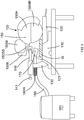
Figure 1 is a side view of the tool according to the invention; -
Figures 2 is a block diagram with the main electronic components of the tool, along with a schematic diagram of a protection circuit within the tool. - Referring now to the drawings, a power tool, such as
miter saw 100, which has abase assembly 110, a table 120 rotatably disposed on thebase assembly 110, asupport section 130 rotatably connected to the table 120, at least oneguide bar 140 fixedly attached to or sliding along thesupport section 130, and asaw assembly 150 sliding along or fixedly attached to the guide bar(s) 140. Ifmultiple guide bars 140 are used, it is preferable to attach anend cap 141 to the ends of theguide bars 140 in order to ensure parallel alignment between theguide bars 140. - The
saw assembly 150 preferably has a saw support section 150SS fixedly attached to the guide bar(s) 140, asaw assembly housing 150H pivotably attached to the saw support section 150SS, amotor 150M supported by thesaw assembly housing 150H, and a saw blade 150MB disposed on an arbor (not shown) and driven bymotor 150M. Persons skilled in the art will recognize that sawassembly housing 150H (and thus saw blade 150MB) may be pivoted downwardly for cutting a workpiece W disposed on the table 120.Saw assembly housing 150H may have a handle (not shown) for sliding thesaw assembly 150 relative to supportsection 130 and/or for downwardly pivoting thesaw assembly housing 150H. - Persons skilled in the art will recognize that workpiece W may be placed against a
fence 121 which is preferably attached tobase assembly 110 and/or table 120. - Miter saw 100 may be powered by AC power and/or power tool battery pack(s) 150B. Persons skilled in the art will recognize that miter saw 100 may receive AC power having a voltage between 120 volts and 240 volts. Similarly, miter saw 100 may receive DC power from the battery pack(s) 150B having a total voltage between 15 volts and 250 volts.
- Referring to
FIG. 2 , the AC power and/or the power received from power tool battery pack(s) 150B may be processed by apower supply circuit 161, which supplies power to motor 150M.Power supply circuit 161 may have a bridge rectifier for converting the AC power into DC. A DC power converter then can lower the voltage to be used by different components withinmiter saw 100.Power supply circuit 161 may have IGBT or MOSFET transistors orhigh power diodes 161D. - The power supplied by
power supply circuit 161 may supplied to aninverter circuit 163 for converting DC power supplied bypower supply circuit 161 to AC power. Such AC power is then supplied tomotor 150M. Acapacitor 165 may be disposed betweenpower supply circuit 161 andinverter circuit 163 to smoothen out the output ofpower supply circuit 161. - A
controller circuit 162 preferably controls the amount of power provided tomotor 150M by interacting with or controlling thepower supply circuit 161 and/orinverter circuit 163. -
Power supply circuit 161 may have at least onepower line 163. Such power line(s)163 may distribute DC power. It may be preferable to provide anESD protection circuit 164 onpower line 163. -
Protection circuit 164 contains at least one resistor R1 disposed betweenpower line 163 and at least one of thebase assembly 110, table 120,support section 130, guide bar(s) 140, and sawassembly 150. Resistor R1 will preferably dissipate the electric static charge and prevent a damaging ESD. Other resistors R2, R3 may be connected in series to resistor R1. In theexemplary protection circuit 164 shown inFIG. 2 , resistor R1 is a low impedance resistor that helps the circuit comply with electromagnetic compatibility (EMC) requirements. Resistors R2, R3 are the high impedance resistors intended to provide the discharge path back to potential ground. - It may also be advantageous to connect at least one capacitor C1 in parallel with resistor R2. Preferably a second capacitor C2 is connected in series with capacitor C1 and connected in parallel to resistor R3.
- Such arrangement provides a path for ESD actually jumping to at least one of the
base assembly 110, table 120,support section 130, guide bar(s) 140, and sawassembly 150. The added capacitor(s) C1, C2 preferably provide a low impedance path to electronic components that are more immune to ESD, such as thecapacitor 165, instead of directly flowing to IGBT or MOSFET transistors orhigh power diodes 161D inpower supply circuit 161. Persons skilled in the art will recognize that the ESD could travel through capacitors C1, C2, throughcapacitor 165, and then towards the IGBT or MOSFET transistors orhigh power diodes 161D alongpower line 163. - Preferably the values of the components are as follow:
R1 360 Ω R2 1 MΩ R3 1 MΩ C1 4.7 nF C2 4.7 nF - This arrangement is useful even if the static charge build-up occurs on a separate device connected to
miter saw 100. Referring toFIG. 1 ,miter saw 100 may have adust collector 170, which is connected to ahose 180, which in turn may be connected to avacuum 181. As mentioned above, particles moving through air through thehose 180 can build significant static charges inhose 180. These static charges can be discharged unto miter saw 100. Protection circuit 164 (and in particular capacitors C1 and/or C2) provide a low impedance path to electronic components that are more immune to ESD so as to minimize any possible damage to more sensitive components. - Persons skilled in the art will recognize that
hose 180 may be electrically connected to at least one of thebase assembly 110, table 120,support section 130, guide bar(s) 140, and sawassembly 150 to prevent a build-up of static charge. Such electric connection may be accomplished through conductive coatings onhose 180 contacting at least one of thebase assembly 110, table 120,support section 130, guide bar(s) 140, and sawassembly 150. Alternatively, awire 180W may be wrapped aroundhose 180 and electrically connected to at least one of thebase assembly 110, table 120,support section 130, guide bar(s) 140, andsaw assembly 150. - It will be understood that the above description and the drawings are examples of particular implementations of the invention, but that other implementations of the invention are included in the scope of the claims.
Claims (13)
- A power tool comprising:a housing,a motor disposed within the housing,a power supply circuit for providing power to the motor,a controller circuit for controlling the power provided to the motor, andan electric static discharge (ESD) protection circuit connected to the power supply circuit and the housing.
- The power tool of Claim 1, wherein the ESD protection circuit comprises a first resistor connected to the power supply circuit and the housing.
- The power tool of Claim 2, wherein the first resistor is a high impedance resistor.
- The power tool of Claim 3, further comprising a first capacitor connected in parallel to the first resistor.
- The power tool of Claim 4, further comprising a second resistor connected in series to the first resistor, and a second capacitor connected in series to the first capacitor and in parallel to the second resistor.
- The power tool of Claim 5, further comprising a third resistor connected in series to the first resistor and the power supply circuit.
- The power tool of Claim 6, wherein the third resistor is a low impedance resistor.
- The power tool of Claim 2, wherein the first resistor is a low impedance resistor.
- The power tool of Claim 8, further comprising a first capacitor connected in series to the first resistor.
- The power tool of Claim 9, further comprising a second resistor connected in series to the first resistor, and in parallel to the first capacitor.
- The power tool of Claim 10, wherein the second resistor is a high impedance resistor.
- The power tool of Claim 10, further comprising a third resistor connected in series to the second resistor, and a second capacitor connected in series to the first capacitor and in parallel to the second resistor.
- The power tool of Claim 12, wherein the third resistor is a high impedance resistor support section 130, guide bar(s) 140, and saw assembly 150. Resistor R1 will preferably dissipate the electric static charge and prevent a damaging ESD. Other resistors R2, R3 may be connected in series to resistor R1. In the exemplary protection circuit 164 shown in FIG. 2, resistor R1 is a low impedance resistor that helps the circuit comply with electromagnetic compatibility (EMC) requirements. Resistors R2, R3 are the high impedance resistors intended to provide the discharge path back to potential ground. It may also be advantageous to connect at least one capacitor C1 in parallel with resistor R2. Preferably a second capacitor C2 is connected in series with capacitor C1 and connected in parallel to resistor R3.
Applications Claiming Priority (1)
| Application Number | Priority Date | Filing Date | Title |
|---|---|---|---|
| US201862688098P | 2018-06-21 | 2018-06-21 |
Publications (2)
| Publication Number | Publication Date |
|---|---|
| EP3616849A1 true EP3616849A1 (en) | 2020-03-04 |
| EP3616849B1 EP3616849B1 (en) | 2021-11-03 |
Family
ID=68982318
Family Applications (1)
| Application Number | Title | Priority Date | Filing Date |
|---|---|---|---|
| EP19179616.8A Active EP3616849B1 (en) | 2018-06-21 | 2019-06-12 | Electric static discharge protection for power tools |
Country Status (2)
| Country | Link |
|---|---|
| US (1) | US10992207B2 (en) |
| EP (1) | EP3616849B1 (en) |
Cited By (1)
| Publication number | Priority date | Publication date | Assignee | Title |
|---|---|---|---|---|
| US12597666B2 (en) | 2021-04-19 | 2026-04-07 | Black & Decker Inc. | Nosecone to battery connection in power tool |
Families Citing this family (3)
| Publication number | Priority date | Publication date | Assignee | Title |
|---|---|---|---|---|
| JP6886787B2 (en) * | 2016-08-03 | 2021-06-16 | 東芝ライフスタイル株式会社 | Electrical equipment and vacuum cleaner |
| CN113785667A (en) * | 2019-05-01 | 2021-12-10 | 米沃奇电动工具公司 | Electrostatic discharge mitigation for power tools |
| CN116191379A (en) * | 2022-12-09 | 2023-05-30 | 广东博力威科技股份有限公司 | Battery metal shell electrostatic treatment circuit |
Citations (3)
| Publication number | Priority date | Publication date | Assignee | Title |
|---|---|---|---|---|
| EP1104224A1 (en) * | 1999-11-26 | 2001-05-30 | Sony Corporation | Electronic apparatus with static voltage discharging means |
| WO2016138961A1 (en) * | 2015-03-05 | 2016-09-09 | Husqvarna Ab | Esd prevention on hand-held, battery powered equipment |
| WO2017210091A1 (en) * | 2016-05-31 | 2017-12-07 | Sd3, Llc | Detection systems for power tools with active injury mitigation technology |
Family Cites Families (3)
| Publication number | Priority date | Publication date | Assignee | Title |
|---|---|---|---|---|
| US9013842B2 (en) * | 2011-01-10 | 2015-04-21 | Infineon Technologies Ag | Semiconductor ESD circuit and method |
| US10050572B2 (en) * | 2014-12-19 | 2018-08-14 | Black & Decker Inc. | Power tool with electric motor and auxiliary switch path |
| DE102017130647A1 (en) * | 2017-12-20 | 2019-06-27 | Ebm-Papst Mulfingen Gmbh & Co. Kg | Device for reducing harmful bearing stresses |
-
2019
- 2019-06-10 US US16/436,138 patent/US10992207B2/en active Active
- 2019-06-12 EP EP19179616.8A patent/EP3616849B1/en active Active
Patent Citations (3)
| Publication number | Priority date | Publication date | Assignee | Title |
|---|---|---|---|---|
| EP1104224A1 (en) * | 1999-11-26 | 2001-05-30 | Sony Corporation | Electronic apparatus with static voltage discharging means |
| WO2016138961A1 (en) * | 2015-03-05 | 2016-09-09 | Husqvarna Ab | Esd prevention on hand-held, battery powered equipment |
| WO2017210091A1 (en) * | 2016-05-31 | 2017-12-07 | Sd3, Llc | Detection systems for power tools with active injury mitigation technology |
Cited By (1)
| Publication number | Priority date | Publication date | Assignee | Title |
|---|---|---|---|---|
| US12597666B2 (en) | 2021-04-19 | 2026-04-07 | Black & Decker Inc. | Nosecone to battery connection in power tool |
Also Published As
| Publication number | Publication date |
|---|---|
| EP3616849B1 (en) | 2021-11-03 |
| US20190393761A1 (en) | 2019-12-26 |
| US10992207B2 (en) | 2021-04-27 |
Similar Documents
| Publication | Publication Date | Title |
|---|---|---|
| EP3616849B1 (en) | Electric static discharge protection for power tools | |
| US10469006B2 (en) | Power tool with electric motor and auxiliary switch path | |
| JP5663353B2 (en) | Electric tool system | |
| CN104097188B (en) | The interlocking system of dust arrester | |
| JP5593200B2 (en) | Electric tool system | |
| CN207368867U (en) | Portable Power Supplies, Portable DC Power Supplies & Kits | |
| TWI489763B (en) | Power tool system and power supply device | |
| CN103009354A (en) | Tool accessory equipment | |
| FI3524110T3 (en) | Suction device with a charger | |
| CN222515190U (en) | Battery charger | |
| WO2016100891A1 (en) | Power tool with electric motor and auxiliary switch path | |
| US20070090796A1 (en) | Power adapter for power tools | |
| CN114846709A (en) | Electric processing appliance with energy supply device | |
| JP6923068B2 (en) | Power supply unit, and system consisting of power supply unit and power tool | |
| WO2016138961A1 (en) | Esd prevention on hand-held, battery powered equipment | |
| US11750069B2 (en) | Line conditioning accessory and protective circuit for power tool | |
| CN107231006B (en) | AC/DC power supply control device for AC/DC dual-purpose dust collector and dust collector | |
| CN1990192B (en) | Suction device for a handheld power tool | |
| US20220190617A1 (en) | Power Tool External Power Supply Assembly | |
| US12394996B2 (en) | Battery-powered system, battery pack, electric work machine, and charger | |
| JPWO2018155073A1 (en) | Electric tool | |
| WO2021054302A1 (en) | Power supply device, cable-equipped power supply device, and electric tool | |
| US20240416482A1 (en) | Electric tool grinding machine with static electricity dissipation | |
| CN105356443A (en) | Electric tool and power-off protection system thereof | |
| US20200030957A1 (en) | Power tool and accessory system |
Legal Events
| Date | Code | Title | Description |
|---|---|---|---|
| PUAI | Public reference made under article 153(3) epc to a published international application that has entered the european phase |
Free format text: ORIGINAL CODE: 0009012 |
|
| STAA | Information on the status of an ep patent application or granted ep patent |
Free format text: STATUS: THE APPLICATION HAS BEEN PUBLISHED |
|
| AK | Designated contracting states |
Kind code of ref document: A1 Designated state(s): AL AT BE BG CH CY CZ DE DK EE ES FI FR GB GR HR HU IE IS IT LI LT LU LV MC MK MT NL NO PL PT RO RS SE SI SK SM TR |
|
| AX | Request for extension of the european patent |
Extension state: BA ME |
|
| STAA | Information on the status of an ep patent application or granted ep patent |
Free format text: STATUS: REQUEST FOR EXAMINATION WAS MADE |
|
| 17P | Request for examination filed |
Effective date: 20200901 |
|
| RBV | Designated contracting states (corrected) |
Designated state(s): AL AT BE BG CH CY CZ DE DK EE ES FI FR GB GR HR HU IE IS IT LI LT LU LV MC MK MT NL NO PL PT RO RS SE SI SK SM TR |
|
| GRAP | Despatch of communication of intention to grant a patent |
Free format text: ORIGINAL CODE: EPIDOSNIGR1 |
|
| STAA | Information on the status of an ep patent application or granted ep patent |
Free format text: STATUS: GRANT OF PATENT IS INTENDED |
|
| INTG | Intention to grant announced |
Effective date: 20210611 |
|
| RIN1 | Information on inventor provided before grant (corrected) |
Inventor name: ESHLEMAN, SCOTT J. Inventor name: WAIKAR, SHAILESH P Inventor name: PAI, GANAPATI K. Inventor name: NARBUT, JOSEPH |
|
| GRAS | Grant fee paid |
Free format text: ORIGINAL CODE: EPIDOSNIGR3 |
|
| GRAA | (expected) grant |
Free format text: ORIGINAL CODE: 0009210 |
|
| STAA | Information on the status of an ep patent application or granted ep patent |
Free format text: STATUS: THE PATENT HAS BEEN GRANTED |
|
| AK | Designated contracting states |
Kind code of ref document: B1 Designated state(s): AL AT BE BG CH CY CZ DE DK EE ES FI FR GB GR HR HU IE IS IT LI LT LU LV MC MK MT NL NO PL PT RO RS SE SI SK SM TR |
|
| REG | Reference to a national code |
Ref country code: GB Ref legal event code: FG4D |
|
| REG | Reference to a national code |
Ref country code: AT Ref legal event code: REF Ref document number: 1443552 Country of ref document: AT Kind code of ref document: T Effective date: 20211115 Ref country code: CH Ref legal event code: EP |
|
| REG | Reference to a national code |
Ref country code: DE Ref legal event code: R096 Ref document number: 602019008853 Country of ref document: DE |
|
| REG | Reference to a national code |
Ref country code: IE Ref legal event code: FG4D |
|
| REG | Reference to a national code |
Ref country code: LT Ref legal event code: MG9D |
|
| REG | Reference to a national code |
Ref country code: NL Ref legal event code: MP Effective date: 20211103 |
|
| REG | Reference to a national code |
Ref country code: AT Ref legal event code: MK05 Ref document number: 1443552 Country of ref document: AT Kind code of ref document: T Effective date: 20211103 |
|
| PG25 | Lapsed in a contracting state [announced via postgrant information from national office to epo] |
Ref country code: RS Free format text: LAPSE BECAUSE OF FAILURE TO SUBMIT A TRANSLATION OF THE DESCRIPTION OR TO PAY THE FEE WITHIN THE PRESCRIBED TIME-LIMIT Effective date: 20211103 Ref country code: LT Free format text: LAPSE BECAUSE OF FAILURE TO SUBMIT A TRANSLATION OF THE DESCRIPTION OR TO PAY THE FEE WITHIN THE PRESCRIBED TIME-LIMIT Effective date: 20211103 Ref country code: FI Free format text: LAPSE BECAUSE OF FAILURE TO SUBMIT A TRANSLATION OF THE DESCRIPTION OR TO PAY THE FEE WITHIN THE PRESCRIBED TIME-LIMIT Effective date: 20211103 Ref country code: BG Free format text: LAPSE BECAUSE OF FAILURE TO SUBMIT A TRANSLATION OF THE DESCRIPTION OR TO PAY THE FEE WITHIN THE PRESCRIBED TIME-LIMIT Effective date: 20220203 Ref country code: AT Free format text: LAPSE BECAUSE OF FAILURE TO SUBMIT A TRANSLATION OF THE DESCRIPTION OR TO PAY THE FEE WITHIN THE PRESCRIBED TIME-LIMIT Effective date: 20211103 |
|
| PG25 | Lapsed in a contracting state [announced via postgrant information from national office to epo] |
Ref country code: IS Free format text: LAPSE BECAUSE OF FAILURE TO SUBMIT A TRANSLATION OF THE DESCRIPTION OR TO PAY THE FEE WITHIN THE PRESCRIBED TIME-LIMIT Effective date: 20220303 Ref country code: SE Free format text: LAPSE BECAUSE OF FAILURE TO SUBMIT A TRANSLATION OF THE DESCRIPTION OR TO PAY THE FEE WITHIN THE PRESCRIBED TIME-LIMIT Effective date: 20211103 Ref country code: PT Free format text: LAPSE BECAUSE OF FAILURE TO SUBMIT A TRANSLATION OF THE DESCRIPTION OR TO PAY THE FEE WITHIN THE PRESCRIBED TIME-LIMIT Effective date: 20220303 Ref country code: PL Free format text: LAPSE BECAUSE OF FAILURE TO SUBMIT A TRANSLATION OF THE DESCRIPTION OR TO PAY THE FEE WITHIN THE PRESCRIBED TIME-LIMIT Effective date: 20211103 Ref country code: NO Free format text: LAPSE BECAUSE OF FAILURE TO SUBMIT A TRANSLATION OF THE DESCRIPTION OR TO PAY THE FEE WITHIN THE PRESCRIBED TIME-LIMIT Effective date: 20220203 Ref country code: NL Free format text: LAPSE BECAUSE OF FAILURE TO SUBMIT A TRANSLATION OF THE DESCRIPTION OR TO PAY THE FEE WITHIN THE PRESCRIBED TIME-LIMIT Effective date: 20211103 Ref country code: LV Free format text: LAPSE BECAUSE OF FAILURE TO SUBMIT A TRANSLATION OF THE DESCRIPTION OR TO PAY THE FEE WITHIN THE PRESCRIBED TIME-LIMIT Effective date: 20211103 Ref country code: HR Free format text: LAPSE BECAUSE OF FAILURE TO SUBMIT A TRANSLATION OF THE DESCRIPTION OR TO PAY THE FEE WITHIN THE PRESCRIBED TIME-LIMIT Effective date: 20211103 Ref country code: GR Free format text: LAPSE BECAUSE OF FAILURE TO SUBMIT A TRANSLATION OF THE DESCRIPTION OR TO PAY THE FEE WITHIN THE PRESCRIBED TIME-LIMIT Effective date: 20220204 Ref country code: ES Free format text: LAPSE BECAUSE OF FAILURE TO SUBMIT A TRANSLATION OF THE DESCRIPTION OR TO PAY THE FEE WITHIN THE PRESCRIBED TIME-LIMIT Effective date: 20211103 |
|
| PG25 | Lapsed in a contracting state [announced via postgrant information from national office to epo] |
Ref country code: SM Free format text: LAPSE BECAUSE OF FAILURE TO SUBMIT A TRANSLATION OF THE DESCRIPTION OR TO PAY THE FEE WITHIN THE PRESCRIBED TIME-LIMIT Effective date: 20211103 Ref country code: SK Free format text: LAPSE BECAUSE OF FAILURE TO SUBMIT A TRANSLATION OF THE DESCRIPTION OR TO PAY THE FEE WITHIN THE PRESCRIBED TIME-LIMIT Effective date: 20211103 Ref country code: RO Free format text: LAPSE BECAUSE OF FAILURE TO SUBMIT A TRANSLATION OF THE DESCRIPTION OR TO PAY THE FEE WITHIN THE PRESCRIBED TIME-LIMIT Effective date: 20211103 Ref country code: EE Free format text: LAPSE BECAUSE OF FAILURE TO SUBMIT A TRANSLATION OF THE DESCRIPTION OR TO PAY THE FEE WITHIN THE PRESCRIBED TIME-LIMIT Effective date: 20211103 Ref country code: DK Free format text: LAPSE BECAUSE OF FAILURE TO SUBMIT A TRANSLATION OF THE DESCRIPTION OR TO PAY THE FEE WITHIN THE PRESCRIBED TIME-LIMIT Effective date: 20211103 Ref country code: CZ Free format text: LAPSE BECAUSE OF FAILURE TO SUBMIT A TRANSLATION OF THE DESCRIPTION OR TO PAY THE FEE WITHIN THE PRESCRIBED TIME-LIMIT Effective date: 20211103 |
|
| REG | Reference to a national code |
Ref country code: DE Ref legal event code: R097 Ref document number: 602019008853 Country of ref document: DE |
|
| PLBE | No opposition filed within time limit |
Free format text: ORIGINAL CODE: 0009261 |
|
| STAA | Information on the status of an ep patent application or granted ep patent |
Free format text: STATUS: NO OPPOSITION FILED WITHIN TIME LIMIT |
|
| 26N | No opposition filed |
Effective date: 20220804 |
|
| PG25 | Lapsed in a contracting state [announced via postgrant information from national office to epo] |
Ref country code: AL Free format text: LAPSE BECAUSE OF FAILURE TO SUBMIT A TRANSLATION OF THE DESCRIPTION OR TO PAY THE FEE WITHIN THE PRESCRIBED TIME-LIMIT Effective date: 20211103 |
|
| PG25 | Lapsed in a contracting state [announced via postgrant information from national office to epo] |
Ref country code: SI Free format text: LAPSE BECAUSE OF FAILURE TO SUBMIT A TRANSLATION OF THE DESCRIPTION OR TO PAY THE FEE WITHIN THE PRESCRIBED TIME-LIMIT Effective date: 20211103 |
|
| PG25 | Lapsed in a contracting state [announced via postgrant information from national office to epo] |
Ref country code: MC Free format text: LAPSE BECAUSE OF FAILURE TO SUBMIT A TRANSLATION OF THE DESCRIPTION OR TO PAY THE FEE WITHIN THE PRESCRIBED TIME-LIMIT Effective date: 20211103 |
|
| REG | Reference to a national code |
Ref country code: CH Ref legal event code: PL |
|
| REG | Reference to a national code |
Ref country code: BE Ref legal event code: MM Effective date: 20220630 |
|
| PG25 | Lapsed in a contracting state [announced via postgrant information from national office to epo] |
Ref country code: LU Free format text: LAPSE BECAUSE OF NON-PAYMENT OF DUE FEES Effective date: 20220612 Ref country code: LI Free format text: LAPSE BECAUSE OF NON-PAYMENT OF DUE FEES Effective date: 20220630 Ref country code: IE Free format text: LAPSE BECAUSE OF NON-PAYMENT OF DUE FEES Effective date: 20220612 Ref country code: FR Free format text: LAPSE BECAUSE OF NON-PAYMENT OF DUE FEES Effective date: 20220630 Ref country code: CH Free format text: LAPSE BECAUSE OF NON-PAYMENT OF DUE FEES Effective date: 20220630 |
|
| PG25 | Lapsed in a contracting state [announced via postgrant information from national office to epo] |
Ref country code: IT Free format text: LAPSE BECAUSE OF FAILURE TO SUBMIT A TRANSLATION OF THE DESCRIPTION OR TO PAY THE FEE WITHIN THE PRESCRIBED TIME-LIMIT Effective date: 20211103 Ref country code: BE Free format text: LAPSE BECAUSE OF NON-PAYMENT OF DUE FEES Effective date: 20220630 |
|
| PG25 | Lapsed in a contracting state [announced via postgrant information from national office to epo] |
Ref country code: MK Free format text: LAPSE BECAUSE OF FAILURE TO SUBMIT A TRANSLATION OF THE DESCRIPTION OR TO PAY THE FEE WITHIN THE PRESCRIBED TIME-LIMIT Effective date: 20211103 Ref country code: CY Free format text: LAPSE BECAUSE OF FAILURE TO SUBMIT A TRANSLATION OF THE DESCRIPTION OR TO PAY THE FEE WITHIN THE PRESCRIBED TIME-LIMIT Effective date: 20211103 |
|
| PG25 | Lapsed in a contracting state [announced via postgrant information from national office to epo] |
Ref country code: HU Free format text: LAPSE BECAUSE OF FAILURE TO SUBMIT A TRANSLATION OF THE DESCRIPTION OR TO PAY THE FEE WITHIN THE PRESCRIBED TIME-LIMIT; INVALID AB INITIO Effective date: 20190612 |
|
| PG25 | Lapsed in a contracting state [announced via postgrant information from national office to epo] |
Ref country code: TR Free format text: LAPSE BECAUSE OF FAILURE TO SUBMIT A TRANSLATION OF THE DESCRIPTION OR TO PAY THE FEE WITHIN THE PRESCRIBED TIME-LIMIT Effective date: 20211103 |
|
| PG25 | Lapsed in a contracting state [announced via postgrant information from national office to epo] |
Ref country code: MT Free format text: LAPSE BECAUSE OF FAILURE TO SUBMIT A TRANSLATION OF THE DESCRIPTION OR TO PAY THE FEE WITHIN THE PRESCRIBED TIME-LIMIT Effective date: 20211103 |
|
| PGFP | Annual fee paid to national office [announced via postgrant information from national office to epo] |
Ref country code: DE Payment date: 20250618 Year of fee payment: 7 |
|
| PGFP | Annual fee paid to national office [announced via postgrant information from national office to epo] |
Ref country code: GB Payment date: 20250620 Year of fee payment: 7 |