EP3616588A1 - Handle for a vacuum cleaner - Google Patents
Handle for a vacuum cleaner Download PDFInfo
- Publication number
- EP3616588A1 EP3616588A1 EP18191258.5A EP18191258A EP3616588A1 EP 3616588 A1 EP3616588 A1 EP 3616588A1 EP 18191258 A EP18191258 A EP 18191258A EP 3616588 A1 EP3616588 A1 EP 3616588A1
- Authority
- EP
- European Patent Office
- Prior art keywords
- handle
- vacuum cleaner
- cleaner body
- spring
- protrusion
- Prior art date
- Legal status (The legal status is an assumption and is not a legal conclusion. Google has not performed a legal analysis and makes no representation as to the accuracy of the status listed.)
- Granted
Links
Images

Classifications
-
- A—HUMAN NECESSITIES
- A47—FURNITURE; DOMESTIC ARTICLES OR APPLIANCES; COFFEE MILLS; SPICE MILLS; SUCTION CLEANERS IN GENERAL
- A47L—DOMESTIC WASHING OR CLEANING; SUCTION CLEANERS IN GENERAL
- A47L9/00—Details or accessories of suction cleaners, e.g. mechanical means for controlling the suction or for effecting pulsating action; Storing devices specially adapted to suction cleaners or parts thereof; Carrying-vehicles specially adapted for suction cleaners
- A47L9/32—Handles
- A47L9/327—Handles for suction cleaners with hose between nozzle and casing
Definitions
- the present invention relates to a handle for a vacuum cleaner which is pivotally mounted on a vacuum cleaner body and which can be moved between a first position in which the handle is located substantially horizontal with respect to the vacuum cleaner body and a second position in which the handle is substantially vertical with respect to the vacuum cleaner body.
- the patent application CN 101 879 714 A1 discloses a handle folding mechanism.
- the mechanism comprises a body, a handle and a locking mechanism, wherein an end part of the handle, which is connected with a rotating shaft, is a pivoted part; the pivoted part is provided with a clamping groove; the locking mechanism comprises a locking piece which is elastically arranged on the body; the pivoted part is provided with a friction groove and a positioning groove; the friction groove extends along the outer circumferential surface of the pivoted part; the positioning groove is formed in the clamping groove; a position on the locking piece, which is opposite to the friction groove, is provided with a convex rib projecting out of the surface of the locking piece; when the locking mechanism is in a locking state, the locking piece is clamped in the clamping groove, the convex rib is clamped in the positioning groove and the body is relatively fixed with the handle; and when the locking mechanism is in an unlocking state, the locking piece is separated from the clamping groove, the convex rib
- the patent application WO 2010 092 061 A1 discloses an invention which relates to a suction cleaning device comprising a suction apparatus, a base that can be moved and on which the suction apparatus is arranged, and a handle that can be swiveled back and forth between a swiveled-in position and a swiveled-out position and that can be fixed in the swiveled-out position by means of a locking device.
- the locking device comprise at least one release element that can be actuated by the user for releasing the handle in the swiveled-out position thereof.
- the patent application WO 2010 061 299 A1 shows a robotic vacuum cleaner comprising sensor means for detecting physical contact with stationary objects in the environment of the vacuum cleaner.
- the vacuum cleaner comprises a handle for carrying the vacuum cleaner by hand.
- the handle can be in a second position whereby the handle is located close to the body of the vacuum cleaner, whereby the sensor means detect forces exerted on the handle during operation of the vacuum cleaner.
- a handle for a vacuum cleaner whereby a handle in a second position has at least two positions, namely a lower position in which the handle can be rotated freely and an upper position in which a hook of a spring engages a protrusion of the vacuum cleaner body.
- the handle is an element of the vacuum cleaner which is pivotally mounted on the vacuum cleaner body and which is provided for the carrying purposes.
- the handle has two main positions: a first and a second position. In the first position the handle is folded into a stored position in which the handle is substantially horizontal and close to the vacuum cleaner body. During the vacuuming process or during storage of the vacuum cleaner the handle stays in the first position. The positive effect is that the handle does not protrude over the vacuum cleaner body so the manipulation the vacuum cleaner hose is easy.
- the handle In the second position the handle is substantially vertical.
- the second position is an unfolded position.
- the second position of the handle has two variants: a lower position in which the handle can be rotated freely and an upper position in which a hook of a spring engages a protrusion of the vacuum cleaner body.
- the handle In the lower position the handle can be rotated freely what means that the handle can be folded into first position without using much force by the user.
- the hook of a spring which both are parts of the handle engages a protrusion of the vacuum cleaner body.
- the hook is a small protrusion designed as a part on the spring.
- the shape of the hook matches the shape of the protrusion of the vacuum cleaner body. The positive effect is that the engagement of the hook with the protrusion is firm and reliable.
- the spring is pressed by a wall of the vacuum cleaner body in the upper position of the handle.
- the handle moves to the upper position and causes the spring compression which is caused by the wall of the vacuum cleaner.
- the handle moves from the upper position to the lower position automatically by the force of the spring.
- the handle In the upper position the handle is blocked against rotation.
- the only possible move for the handle is return to the lower position.
- the handle After releasing the handle from user's hand the handle backs automatically to the lower position by the force of the spring and to the gravity.
- the advantage is that the handle returns to the lower position without using any force or any activity of the user.
- the handle moves to the lower position automatically thanks only to the spring expansion force and the force of the gravity.
- the spring cooperates with a guiding surface as the handle moves between the first position and the second position.
- the guiding surface is an arc shaped surface on which the spring is sliding. The positive effect is that the movement of the handle is smooth and manipulation of the handle is convenient for the user.
- the handle and the spring are one element.
- the spring and the handle are designed as one part. The advantage is that the production process is simple and the mounting operation is eliminated.
- the spring and the handle can be produced as two separate parts and mounted during mounting process.
- the handle is a two part element.
- the handle consist of two part which are mounted together during assembling process.
- the positive effect is that the stiffness of the handle is great and the production is simpler as the injection moulds are not complicated as in case of one part.
- the handle can consist of more than two parts.
- the vacuum cleaner body is provided with a blocking element.
- the blocking element is a small protrusion placed on the vacuum cleaner body.
- the blocking element is provided in order to hold the handle in the vertical position and prevent the handle from moving into different positions, especially to the substantially horizontal first position. In order to move the handle into the first position the user need to use some power to force the spring to pass over the blocking element. The advantage is that the accidental movement of the handle is prevented.
- a pin of the handle cooperates with a socket of the vacuum cleaner body.
- the handle has two pins. Each of the pins is placed at the end portions of the handle
- the vacuum cleaner body has two sockets which are placed on two opposite sides of the vacuum cleaner body and each pin is inserted into one socket.
- the handle is mounted on the vacuum cleaner body during mounting process. The advantage is that the mounting is simple and fast.
- the diameter of the socket is greater than the diameter of the pin.
- the socket has the oval shape and the height of the socket is greater than the width in order to let the handle in the second position to move from the lower position to the upper position.
- the diameter of the pin is smaller than the diameter of the socket for the same purpose. The positive effect is that the movement of the handle in the vertical direction is possible.
- the present invention provides a simple and efficient solution for blocking the handle of the vacuum cleaner in a position in which the vacuum cleaner can be carried by the user in a safe and comfortable manner.
- the invention also relates to an automatic release system for the handle of a vacuum cleaner.
- Vacuum cleaners are well known in the state of the art devices which are commonly used all over the world in homes as well as in the industry.
- Typical canister vacuum cleaner is a device that uses an air pump to create a partial vacuum to suck up dust and dirt, usually from floors and other surfaces such as upholstery, cushions or curtains. The dirt is collected inside a dust bag or dust receptacle for later disposal.
- vacuum cleaners are provided with handles.
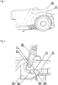
- Fig. 1 shows an isometric view of the vacuum cleaner body 10 with a handle 20 in a first position.
- the handle 20 is in a first position which means that it is substantially horizontal and placed close to the vacuum cleaner body 10.
- the first position is a storage position when the vacuum cleaner is not working or when the vacuum cleaner is working and the handle 20 is folded so that it does not constitute an obstacle for the consumer during vacuuming.
- Fig. 2 shows a cross section of the handle 20 in a lower position.
- the handle When the handle is in unfolded second position it can be moved into a lower position or into an upper position.
- the pin 21 of the handle 20 In the lower position the pin 21 of the handle 20 is placed in the lower area of the socket 11.
- the spring 23 is expanded and touches the wall 15 and the guiding surface 14 of the vacuum cleaner body 10 tangentially.
- the hook 22 is situated at a distance from the protrusion 13.
- the blocking element 12 holds the handle 20 in vertical position in which an automatic move of the handle 20 into folded first position is prevented. In order to move the handle 20 into first position the user has to push the handle 20 with a little force towards the vacuum cleaner body 10.
- Fig. 3 shows a cross section of the handle 20 in an upper position.
- the handle 20 moves in an upper position when the vacuum cleaner is carried by the user.
- the pin 21 of the handle 20 is placed in the upper area of the socket 11.
- the spring 23 is compressed by the wall 15 and the hook 22 engages the protrusion 13.
- the handle 20 in the second upper position is blocked by the blocking element 12 and also by the engagement of the hook 22 with the protrusion 13. After releasing by the user the handle 20 moves down into the lower position automatically by the spring 23 expansion and the gravity.
- Fig. 4 shows an isometric view of the vacuum cleaner body 10 with a handle 20 in a second position. In such position of the handle 20 the vacuum cleaner can be carried by the user or the handle 20 can be moved into the folded first position (not shown on the figure).
- the present invention provides a simple and efficient solution for blocking the handle of the vacuum cleaner in a position in which the vacuum cleaner can be carried by the user in a safe and comfortable manner.
- the invention also relates to an automatic release system for the handle of a vacuum cleaner.
Landscapes
- Engineering & Computer Science (AREA)
- Mechanical Engineering (AREA)
- Electric Vacuum Cleaner (AREA)
Abstract
Description
- The present invention relates to a handle for a vacuum cleaner which is pivotally mounted on a vacuum cleaner body and which can be moved between a first position in which the handle is located substantially horizontal with respect to the vacuum cleaner body and a second position in which the handle is substantially vertical with respect to the vacuum cleaner body.
- The patent application
CN 101 879 714 A1 discloses a handle folding mechanism. The mechanism comprises a body, a handle and a locking mechanism, wherein an end part of the handle, which is connected with a rotating shaft, is a pivoted part; the pivoted part is provided with a clamping groove; the locking mechanism comprises a locking piece which is elastically arranged on the body; the pivoted part is provided with a friction groove and a positioning groove; the friction groove extends along the outer circumferential surface of the pivoted part; the positioning groove is formed in the clamping groove; a position on the locking piece, which is opposite to the friction groove, is provided with a convex rib projecting out of the surface of the locking piece; when the locking mechanism is in a locking state, the locking piece is clamped in the clamping groove, the convex rib is clamped in the positioning groove and the body is relatively fixed with the handle; and when the locking mechanism is in an unlocking state, the locking piece is separated from the clamping groove, the convex rib is arranged in the friction groove in a sliding way, when the handle rotates, the convex rib is only contacted with the friction groove and the locking piece is not contacted with the outer circumferential surface of the pivoted part. Therefore, scratches are only produced at the bottom of the friction groove, the outer surface of the pivoted part is kept bright and clean for a long time and household appliance products are kept attractive for a long time. - The patent application
WO 2010 092 061 A1 discloses an invention which relates to a suction cleaning device comprising a suction apparatus, a base that can be moved and on which the suction apparatus is arranged, and a handle that can be swiveled back and forth between a swiveled-in position and a swiveled-out position and that can be fixed in the swiveled-out position by means of a locking device. In order to develop the suction cleaning device in such a way that the suction cleaning device can be handled in an easier manner, it is proposed that the locking device comprise at least one release element that can be actuated by the user for releasing the handle in the swiveled-out position thereof. - The patent application
WO 2010 061 299 A1 shows a robotic vacuum cleaner comprising sensor means for detecting physical contact with stationary objects in the environment of the vacuum cleaner. The vacuum cleaner comprises a handle for carrying the vacuum cleaner by hand. The handle can be in a second position whereby the handle is located close to the body of the vacuum cleaner, whereby the sensor means detect forces exerted on the handle during operation of the vacuum cleaner. - Presented solutions do not provide an efficient, simple and automatic system for blocking a handle of a vacuum cleaner in position in which the vacuum cleaner can be carried in a safe and convenient way.
- It is the object of the present invention to overcome problems associated with vacuum cleaner handles and provides a simple and efficient automatic blocking and releasing system for a vacuum cleaner handle.
- These objects are solved by a handle for a vacuum cleaner whereby a handle in a second position has at least two positions, namely a lower position in which the handle can be rotated freely and an upper position in which a hook of a spring engages a protrusion of the vacuum cleaner body.
- The handle is an element of the vacuum cleaner which is pivotally mounted on the vacuum cleaner body and which is provided for the carrying purposes. The handle has two main positions: a first and a second position. In the first position the handle is folded into a stored position in which the handle is substantially horizontal and close to the vacuum cleaner body. During the vacuuming process or during storage of the vacuum cleaner the handle stays in the first position. The positive effect is that the handle does not protrude over the vacuum cleaner body so the manipulation the vacuum cleaner hose is easy.
- In the second position the handle is substantially vertical. The second position is an unfolded position. The second position of the handle has two variants: a lower position in which the handle can be rotated freely and an upper position in which a hook of a spring engages a protrusion of the vacuum cleaner body. In the lower position the handle can be rotated freely what means that the handle can be folded into first position without using much force by the user. In the upper position the hook of a spring which both are parts of the handle engages a protrusion of the vacuum cleaner body. The hook is a small protrusion designed as a part on the spring. The shape of the hook matches the shape of the protrusion of the vacuum cleaner body. The positive effect is that the engagement of the hook with the protrusion is firm and reliable.
- When the hook engages a protrusion the handle rotation is blocked. The advantage of blocking the handle in the second position is that swinging the vacuum cleaner back and forth is prevented. Thanks to this blocking system the handling of the vacuum cleaner is comfortable for consumer.
- In a preferred embodiment of the invention the spring is pressed by a wall of the vacuum cleaner body in the upper position of the handle. When the vacuum cleaner is lifted by the user the handle moves to the upper position and causes the spring compression which is caused by the wall of the vacuum cleaner.
- In a preferred embodiment of the invention the handle moves from the upper position to the lower position automatically by the force of the spring. In the upper position the handle is blocked against rotation. The only possible move for the handle is return to the lower position. After releasing the handle from user's hand the handle backs automatically to the lower position by the force of the spring and to the gravity. The advantage is that the handle returns to the lower position without using any force or any activity of the user. The handle moves to the lower position automatically thanks only to the spring expansion force and the force of the gravity.
- In a preferred embodiment of the invention the spring cooperates with a guiding surface as the handle moves between the first position and the second position. The guiding surface is an arc shaped surface on which the spring is sliding. The positive effect is that the movement of the handle is smooth and manipulation of the handle is convenient for the user.
- In another embodiment of the invention the handle and the spring are one element. The spring and the handle are designed as one part. The advantage is that the production process is simple and the mounting operation is eliminated. The spring and the handle can be produced as two separate parts and mounted during mounting process.
- Advantageously the handle is a two part element. The handle consist of two part which are mounted together during assembling process.The positive effect is that the stiffness of the handle is great and the production is simpler as the injection moulds are not complicated as in case of one part. The handle can consist of more than two parts.
- In a favourable embodiment of the invention the vacuum cleaner body is provided with a blocking element. The blocking element is a small protrusion placed on the vacuum cleaner body. The blocking element is provided in order to hold the handle in the vertical position and prevent the handle from moving into different positions, especially to the substantially horizontal first position. In order to move the handle into the first position the user need to use some power to force the spring to pass over the blocking element. The advantage is that the accidental movement of the handle is prevented.
- In another embodiment of the invention a pin of the handle cooperates with a socket of the vacuum cleaner body. The handle has two pins. Each of the pins is placed at the end portions of the handle The vacuum cleaner body has two sockets which are placed on two opposite sides of the vacuum cleaner body and each pin is inserted into one socket. The handle is mounted on the vacuum cleaner body during mounting process. The advantage is that the mounting is simple and fast.
- In another embodiment of the invention the diameter of the socket is greater than the diameter of the pin. The socket has the oval shape and the height of the socket is greater than the width in order to let the handle in the second position to move from the lower position to the upper position. The diameter of the pin is smaller than the diameter of the socket for the same purpose. The positive effect is that the movement of the handle in the vertical direction is possible.
- It is to be understood that both the foregoing general description and the following detailed description are exemplary, and are intended to provide further explanation of the invention as claimed. Other advantages and features of the invention will be apparent from the following description, drawings and claims.
- The present invention provides a simple and efficient solution for blocking the handle of the vacuum cleaner in a position in which the vacuum cleaner can be carried by the user in a safe and comfortable manner. The invention also relates to an automatic release system for the handle of a vacuum cleaner.
- The features of the invention believed to be novel are set forth with particularity in the appended claims. The invention itself, however, may be best understood by reference to the following detailed description of the invention, which describes an exemplary embodiment of the invention, taken in conjunction with the accompanying drawings. Further benefits and advantages of the present invention will become apparent after a careful reading of the detailed description with appropriate reference to the accompanying drawings.
- In the drawings:
- Fig. 1
- exemplary shows an isometric view of the vacuum cleaner body with a handle in a first position;
- Fig. 2
- shows a cross section of the handle in a lower position;
- Fig. 3
- shows a cross section of the handle in an upper position;
- Fig. 4
- shows an isometric view of the vacuum cleaner with a handle in a second position;
- In cooperation with attached drawings, the technical contents and detailed description of the present invention are described thereinafter according to a preferable embodiment, being not used to limit its executing scope. Any equivalent variation and modification made according to appended claims is all covered by the claims claimed by the present invention.
- In the following description of the preferred embodiments of the present invention, similar identical reference numbers designate identical or comparable components.
- Vacuum cleaners are well known in the state of the art devices which are commonly used all over the world in homes as well as in the industry. Typical canister vacuum cleaner is a device that uses an air pump to create a partial vacuum to suck up dust and dirt, usually from floors and other surfaces such as upholstery, cushions or curtains. The dirt is collected inside a dust bag or dust receptacle for later disposal. For the carrying purpose vacuum cleaners are provided with handles.
-
Fig. 1 shows an isometric view of the vacuumcleaner body 10 with ahandle 20 in a first position. Thehandle 20 is in a first position which means that it is substantially horizontal and placed close to the vacuumcleaner body 10. The first position is a storage position when the vacuum cleaner is not working or when the vacuum cleaner is working and thehandle 20 is folded so that it does not constitute an obstacle for the consumer during vacuuming. -
Fig. 2 shows a cross section of thehandle 20 in a lower position. When the handle is in unfolded second position it can be moved into a lower position or into an upper position. In the lower position thepin 21 of thehandle 20 is placed in the lower area of thesocket 11. Thespring 23 is expanded and touches thewall 15 and the guidingsurface 14 of the vacuumcleaner body 10 tangentially. Thehook 22 is situated at a distance from theprotrusion 13. The blockingelement 12 holds thehandle 20 in vertical position in which an automatic move of thehandle 20 into folded first position is prevented. In order to move thehandle 20 into first position the user has to push thehandle 20 with a little force towards the vacuumcleaner body 10. -
Fig. 3 shows a cross section of thehandle 20 in an upper position. Thehandle 20 moves in an upper position when the vacuum cleaner is carried by the user. In the upper position of thehandle 20 thepin 21 of thehandle 20 is placed in the upper area of thesocket 11. Thespring 23 is compressed by thewall 15 and thehook 22 engages theprotrusion 13. Thehandle 20 in the second upper position is blocked by the blockingelement 12 and also by the engagement of thehook 22 with theprotrusion 13. After releasing by the user thehandle 20 moves down into the lower position automatically by thespring 23 expansion and the gravity. -
Fig. 4 shows an isometric view of the vacuumcleaner body 10 with ahandle 20 in a second position. In such position of thehandle 20 the vacuum cleaner can be carried by the user or thehandle 20 can be moved into the folded first position (not shown on the figure). - The present invention provides a simple and efficient solution for blocking the handle of the vacuum cleaner in a position in which the vacuum cleaner can be carried by the user in a safe and comfortable manner. The invention also relates to an automatic release system for the handle of a vacuum cleaner.
-
- 10
- vacuum cleaner body
- 11
- socket
- 12
- blocking element
- 13
- protrusion
- 14
- guiding surface
- 15
- wall
- 20
- handle
- 21
- pin
- 22
- hook
- 23
- spring
Claims (9)
- A handle (20) for a vacuum cleaner which is pivotally mounted on a vacuum cleaner body (10) and which can be moved between a first position in which the handle (20) is located substantially horizontal with respect to the vacuum cleaner body (10) and a second position in which the handle (20) is substantially vertical with respect to the vacuum cleaner body (10) characterized in that the handle (20) in said second position has at least two positions, namely a lower position in which the handle (20) can be rotated freely and an upper position in which a hook (22) of a spring (23) engages a protrusion (13) of the vacuum cleaner body (10).
- The handle (20) according to claim 1, characterized in that the spring (23) is pressed by a wall (15) of the vacuum cleaner body (10) in the upper position of the handle (20).
- The handle (20) according to claim 2, characterized in that the handle (20) moves from the upper position to the lower position automatically by the force of the spring (23).
- The handle (20) according to any of preceding claims, characterized in that the spring (23) cooperates with a guiding surface (14) during movement of the handle (20) between the first position and the second position.
- The handle (20) according to any of preceding claims, characterized in that the handle (20) and the spring (23) are one element.
- The handle (20) according to any of preceding claims, characterized in that the handle (20) is a two part element.
- The handle (20) according to any of preceding claims, characterized in that the vacuum cleaner body (10) is provided with a blocking element (12).
- The handle (20) according to any of preceding claims, characterized in that a pin (21) of the handle (20) cooperates with a socket (11) of the vacuum cleaner body (10).
- The handle (20) according to any of preceding claims, characterized in that the diameter of the socket (11) is greater than the diameter of the pin (21).
Priority Applications (2)
| Application Number | Priority Date | Filing Date | Title |
|---|---|---|---|
| PL18191258T PL3616588T3 (en) | 2018-08-28 | 2018-08-28 | Vacuum cleaner with a handle for carrying the vacuum cleaner |
| EP18191258.5A EP3616588B1 (en) | 2018-08-28 | 2018-08-28 | Vacuum cleaner with a handle for carrying the vacuum cleaner |
Applications Claiming Priority (1)
| Application Number | Priority Date | Filing Date | Title |
|---|---|---|---|
| EP18191258.5A EP3616588B1 (en) | 2018-08-28 | 2018-08-28 | Vacuum cleaner with a handle for carrying the vacuum cleaner |
Publications (2)
| Publication Number | Publication Date |
|---|---|
| EP3616588A1 true EP3616588A1 (en) | 2020-03-04 |
| EP3616588B1 EP3616588B1 (en) | 2021-03-17 |
Family
ID=63442520
Family Applications (1)
| Application Number | Title | Priority Date | Filing Date |
|---|---|---|---|
| EP18191258.5A Active EP3616588B1 (en) | 2018-08-28 | 2018-08-28 | Vacuum cleaner with a handle for carrying the vacuum cleaner |
Country Status (2)
| Country | Link |
|---|---|
| EP (1) | EP3616588B1 (en) |
| PL (1) | PL3616588T3 (en) |
Citations (6)
| Publication number | Priority date | Publication date | Assignee | Title |
|---|---|---|---|---|
| EP0935944A1 (en) * | 1998-02-12 | 1999-08-18 | Aktiebolaget Electrolux | Vacuum cleaner |
| WO2000036970A1 (en) * | 1998-12-18 | 2000-06-29 | Dyson Limited | Portable appliance |
| EP1922973A2 (en) * | 2006-11-20 | 2008-05-21 | BLACK & DECKER INC. | Vacuum with stowable handle |
| WO2010061299A1 (en) | 2008-11-03 | 2010-06-03 | Koninklijke Philips Electronics N.V. | A robotic vacuum cleaner comprising a sensing handle |
| WO2010092061A1 (en) | 2009-02-11 | 2010-08-19 | Alfred Kärcher Gmbh & Co. Kg | Suction cleaning device |
| CN101879714A (en) | 2010-06-23 | 2010-11-10 | 江苏美的春花电器股份有限公司 | A handle folding mechanism |
-
2018
- 2018-08-28 PL PL18191258T patent/PL3616588T3/en unknown
- 2018-08-28 EP EP18191258.5A patent/EP3616588B1/en active Active
Patent Citations (6)
| Publication number | Priority date | Publication date | Assignee | Title |
|---|---|---|---|---|
| EP0935944A1 (en) * | 1998-02-12 | 1999-08-18 | Aktiebolaget Electrolux | Vacuum cleaner |
| WO2000036970A1 (en) * | 1998-12-18 | 2000-06-29 | Dyson Limited | Portable appliance |
| EP1922973A2 (en) * | 2006-11-20 | 2008-05-21 | BLACK & DECKER INC. | Vacuum with stowable handle |
| WO2010061299A1 (en) | 2008-11-03 | 2010-06-03 | Koninklijke Philips Electronics N.V. | A robotic vacuum cleaner comprising a sensing handle |
| WO2010092061A1 (en) | 2009-02-11 | 2010-08-19 | Alfred Kärcher Gmbh & Co. Kg | Suction cleaning device |
| CN101879714A (en) | 2010-06-23 | 2010-11-10 | 江苏美的春花电器股份有限公司 | A handle folding mechanism |
Also Published As
| Publication number | Publication date |
|---|---|
| PL3616588T3 (en) | 2021-09-27 |
| EP3616588B1 (en) | 2021-03-17 |
Similar Documents
| Publication | Publication Date | Title |
|---|---|---|
| US7681279B2 (en) | Vacuum cleaner | |
| CN202078263U (en) | Dust collecting box and dust collecting machine with same | |
| US5839160A (en) | Clutch control mechanical device for the brush axle of a vacuum cleaner | |
| AU2005263889B2 (en) | Handle assembly for a cleaning appliance | |
| CN108309149B (en) | Tool for dust collector and dust collector thereof | |
| US11375862B2 (en) | Cleaner stand and cleaning apparatus having the same | |
| CN102202550B (en) | A robotic vacuum cleaner comprising a sensing handle | |
| KR100592099B1 (en) | Extension pipe support device and vacuum cleaner having the same | |
| EP3616588B1 (en) | Vacuum cleaner with a handle for carrying the vacuum cleaner | |
| KR102268576B1 (en) | Vacuum cleaner | |
| US9232878B2 (en) | Upright type vacuum cleaner | |
| CN108348118A (en) | Cleaning tools and vacuum cleaners | |
| CN203506623U (en) | Off-ground power-off protection structure for dust collector ground brush | |
| RU2619004C2 (en) | Robotic vacuum cleaner with removable dust container | |
| CN205597848U (en) | Suction port body and electric vacuum cleaner equipped with the same | |
| JP2010082237A (en) | Suction nozzle for vacuum cleaner, and suction head for the vacuum cleaner equipped with the same | |
| CN118576116A (en) | Dust collection station and cleaning system | |
| CN109965773B (en) | Vacuum cleaner and floor brush structure of vacuum cleaner | |
| CN219594463U (en) | Cleaning system and base station | |
| CN223416116U (en) | A bracket | |
| KR101356659B1 (en) | Dust collecting unit for vaccum cleaner | |
| CN222549135U (en) | Cleaning device | |
| CN113734727B (en) | Loading and unloading device and rail conveying system | |
| JP2005130887A (en) | Electric vacuum cleaner | |
| KR200353551Y1 (en) | An accessory structure of vacuum cleaner |
Legal Events
| Date | Code | Title | Description |
|---|---|---|---|
| PUAI | Public reference made under article 153(3) epc to a published international application that has entered the european phase |
Free format text: ORIGINAL CODE: 0009012 |
|
| STAA | Information on the status of an ep patent application or granted ep patent |
Free format text: STATUS: THE APPLICATION HAS BEEN PUBLISHED |
|
| AK | Designated contracting states |
Kind code of ref document: A1 Designated state(s): AL AT BE BG CH CY CZ DE DK EE ES FI FR GB GR HR HU IE IS IT LI LT LU LV MC MK MT NL NO PL PT RO RS SE SI SK SM TR |
|
| AX | Request for extension of the european patent |
Extension state: BA ME |
|
| STAA | Information on the status of an ep patent application or granted ep patent |
Free format text: STATUS: REQUEST FOR EXAMINATION WAS MADE |
|
| 17P | Request for examination filed |
Effective date: 20200904 |
|
| RBV | Designated contracting states (corrected) |
Designated state(s): AL AT BE BG CH CY CZ DE DK EE ES FI FR GB GR HR HU IE IS IT LI LT LU LV MC MK MT NL NO PL PT RO RS SE SI SK SM TR |
|
| GRAP | Despatch of communication of intention to grant a patent |
Free format text: ORIGINAL CODE: EPIDOSNIGR1 |
|
| STAA | Information on the status of an ep patent application or granted ep patent |
Free format text: STATUS: GRANT OF PATENT IS INTENDED |
|
| RIC1 | Information provided on ipc code assigned before grant |
Ipc: A47L 9/32 20060101AFI20200928BHEP |
|
| INTG | Intention to grant announced |
Effective date: 20201103 |
|
| GRAS | Grant fee paid |
Free format text: ORIGINAL CODE: EPIDOSNIGR3 |
|
| GRAA | (expected) grant |
Free format text: ORIGINAL CODE: 0009210 |
|
| STAA | Information on the status of an ep patent application or granted ep patent |
Free format text: STATUS: THE PATENT HAS BEEN GRANTED |
|
| AK | Designated contracting states |
Kind code of ref document: B1 Designated state(s): AL AT BE BG CH CY CZ DE DK EE ES FI FR GB GR HR HU IE IS IT LI LT LU LV MC MK MT NL NO PL PT RO RS SE SI SK SM TR |
|
| REG | Reference to a national code |
Ref country code: GB Ref legal event code: FG4D |
|
| REG | Reference to a national code |
Ref country code: CH Ref legal event code: EP |
|
| REG | Reference to a national code |
Ref country code: DE Ref legal event code: R096 Ref document number: 602018013973 Country of ref document: DE |
|
| REG | Reference to a national code |
Ref country code: IE Ref legal event code: FG4D |
|
| REG | Reference to a national code |
Ref country code: AT Ref legal event code: REF Ref document number: 1371428 Country of ref document: AT Kind code of ref document: T Effective date: 20210415 |
|
| REG | Reference to a national code |
Ref country code: LT Ref legal event code: MG9D |
|
| PG25 | Lapsed in a contracting state [announced via postgrant information from national office to epo] |
Ref country code: NO Free format text: LAPSE BECAUSE OF FAILURE TO SUBMIT A TRANSLATION OF THE DESCRIPTION OR TO PAY THE FEE WITHIN THE PRESCRIBED TIME-LIMIT Effective date: 20210617 Ref country code: BG Free format text: LAPSE BECAUSE OF FAILURE TO SUBMIT A TRANSLATION OF THE DESCRIPTION OR TO PAY THE FEE WITHIN THE PRESCRIBED TIME-LIMIT Effective date: 20210617 Ref country code: FI Free format text: LAPSE BECAUSE OF FAILURE TO SUBMIT A TRANSLATION OF THE DESCRIPTION OR TO PAY THE FEE WITHIN THE PRESCRIBED TIME-LIMIT Effective date: 20210317 Ref country code: HR Free format text: LAPSE BECAUSE OF FAILURE TO SUBMIT A TRANSLATION OF THE DESCRIPTION OR TO PAY THE FEE WITHIN THE PRESCRIBED TIME-LIMIT Effective date: 20210317 Ref country code: GR Free format text: LAPSE BECAUSE OF FAILURE TO SUBMIT A TRANSLATION OF THE DESCRIPTION OR TO PAY THE FEE WITHIN THE PRESCRIBED TIME-LIMIT Effective date: 20210618 |
|
| REG | Reference to a national code |
Ref country code: AT Ref legal event code: MK05 Ref document number: 1371428 Country of ref document: AT Kind code of ref document: T Effective date: 20210317 |
|
| REG | Reference to a national code |
Ref country code: NL Ref legal event code: MP Effective date: 20210317 |
|
| PG25 | Lapsed in a contracting state [announced via postgrant information from national office to epo] |
Ref country code: RS Free format text: LAPSE BECAUSE OF FAILURE TO SUBMIT A TRANSLATION OF THE DESCRIPTION OR TO PAY THE FEE WITHIN THE PRESCRIBED TIME-LIMIT Effective date: 20210317 Ref country code: LV Free format text: LAPSE BECAUSE OF FAILURE TO SUBMIT A TRANSLATION OF THE DESCRIPTION OR TO PAY THE FEE WITHIN THE PRESCRIBED TIME-LIMIT Effective date: 20210317 Ref country code: SE Free format text: LAPSE BECAUSE OF FAILURE TO SUBMIT A TRANSLATION OF THE DESCRIPTION OR TO PAY THE FEE WITHIN THE PRESCRIBED TIME-LIMIT Effective date: 20210317 |
|
| PG25 | Lapsed in a contracting state [announced via postgrant information from national office to epo] |
Ref country code: NL Free format text: LAPSE BECAUSE OF FAILURE TO SUBMIT A TRANSLATION OF THE DESCRIPTION OR TO PAY THE FEE WITHIN THE PRESCRIBED TIME-LIMIT Effective date: 20210317 |
|
| PG25 | Lapsed in a contracting state [announced via postgrant information from national office to epo] |
Ref country code: LT Free format text: LAPSE BECAUSE OF FAILURE TO SUBMIT A TRANSLATION OF THE DESCRIPTION OR TO PAY THE FEE WITHIN THE PRESCRIBED TIME-LIMIT Effective date: 20210317 Ref country code: CZ Free format text: LAPSE BECAUSE OF FAILURE TO SUBMIT A TRANSLATION OF THE DESCRIPTION OR TO PAY THE FEE WITHIN THE PRESCRIBED TIME-LIMIT Effective date: 20210317 Ref country code: EE Free format text: LAPSE BECAUSE OF FAILURE TO SUBMIT A TRANSLATION OF THE DESCRIPTION OR TO PAY THE FEE WITHIN THE PRESCRIBED TIME-LIMIT Effective date: 20210317 Ref country code: SM Free format text: LAPSE BECAUSE OF FAILURE TO SUBMIT A TRANSLATION OF THE DESCRIPTION OR TO PAY THE FEE WITHIN THE PRESCRIBED TIME-LIMIT Effective date: 20210317 Ref country code: AT Free format text: LAPSE BECAUSE OF FAILURE TO SUBMIT A TRANSLATION OF THE DESCRIPTION OR TO PAY THE FEE WITHIN THE PRESCRIBED TIME-LIMIT Effective date: 20210317 |
|
| PG25 | Lapsed in a contracting state [announced via postgrant information from national office to epo] |
Ref country code: SK Free format text: LAPSE BECAUSE OF FAILURE TO SUBMIT A TRANSLATION OF THE DESCRIPTION OR TO PAY THE FEE WITHIN THE PRESCRIBED TIME-LIMIT Effective date: 20210317 Ref country code: RO Free format text: LAPSE BECAUSE OF FAILURE TO SUBMIT A TRANSLATION OF THE DESCRIPTION OR TO PAY THE FEE WITHIN THE PRESCRIBED TIME-LIMIT Effective date: 20210317 Ref country code: PT Free format text: LAPSE BECAUSE OF FAILURE TO SUBMIT A TRANSLATION OF THE DESCRIPTION OR TO PAY THE FEE WITHIN THE PRESCRIBED TIME-LIMIT Effective date: 20210719 Ref country code: IS Free format text: LAPSE BECAUSE OF FAILURE TO SUBMIT A TRANSLATION OF THE DESCRIPTION OR TO PAY THE FEE WITHIN THE PRESCRIBED TIME-LIMIT Effective date: 20210717 |
|
| REG | Reference to a national code |
Ref country code: DE Ref legal event code: R097 Ref document number: 602018013973 Country of ref document: DE |
|
| PLBE | No opposition filed within time limit |
Free format text: ORIGINAL CODE: 0009261 |
|
| STAA | Information on the status of an ep patent application or granted ep patent |
Free format text: STATUS: NO OPPOSITION FILED WITHIN TIME LIMIT |
|
| PG25 | Lapsed in a contracting state [announced via postgrant information from national office to epo] |
Ref country code: ES Free format text: LAPSE BECAUSE OF FAILURE TO SUBMIT A TRANSLATION OF THE DESCRIPTION OR TO PAY THE FEE WITHIN THE PRESCRIBED TIME-LIMIT Effective date: 20210317 Ref country code: DK Free format text: LAPSE BECAUSE OF FAILURE TO SUBMIT A TRANSLATION OF THE DESCRIPTION OR TO PAY THE FEE WITHIN THE PRESCRIBED TIME-LIMIT Effective date: 20210317 Ref country code: AL Free format text: LAPSE BECAUSE OF FAILURE TO SUBMIT A TRANSLATION OF THE DESCRIPTION OR TO PAY THE FEE WITHIN THE PRESCRIBED TIME-LIMIT Effective date: 20210317 |
|
| 26N | No opposition filed |
Effective date: 20211220 |
|
| PG25 | Lapsed in a contracting state [announced via postgrant information from national office to epo] |
Ref country code: SI Free format text: LAPSE BECAUSE OF FAILURE TO SUBMIT A TRANSLATION OF THE DESCRIPTION OR TO PAY THE FEE WITHIN THE PRESCRIBED TIME-LIMIT Effective date: 20210317 |
|
| REG | Reference to a national code |
Ref country code: CH Ref legal event code: PL |
|
| PG25 | Lapsed in a contracting state [announced via postgrant information from national office to epo] |
Ref country code: MC Free format text: LAPSE BECAUSE OF FAILURE TO SUBMIT A TRANSLATION OF THE DESCRIPTION OR TO PAY THE FEE WITHIN THE PRESCRIBED TIME-LIMIT Effective date: 20210317 |
|
| REG | Reference to a national code |
Ref country code: BE Ref legal event code: MM Effective date: 20210831 |
|
| PG25 | Lapsed in a contracting state [announced via postgrant information from national office to epo] |
Ref country code: LI Free format text: LAPSE BECAUSE OF NON-PAYMENT OF DUE FEES Effective date: 20210831 Ref country code: IT Free format text: LAPSE BECAUSE OF FAILURE TO SUBMIT A TRANSLATION OF THE DESCRIPTION OR TO PAY THE FEE WITHIN THE PRESCRIBED TIME-LIMIT Effective date: 20210317 Ref country code: CH Free format text: LAPSE BECAUSE OF NON-PAYMENT OF DUE FEES Effective date: 20210831 |
|
| PG25 | Lapsed in a contracting state [announced via postgrant information from national office to epo] |
Ref country code: IS Free format text: LAPSE BECAUSE OF FAILURE TO SUBMIT A TRANSLATION OF THE DESCRIPTION OR TO PAY THE FEE WITHIN THE PRESCRIBED TIME-LIMIT Effective date: 20210717 Ref country code: LU Free format text: LAPSE BECAUSE OF NON-PAYMENT OF DUE FEES Effective date: 20210828 |
|
| PG25 | Lapsed in a contracting state [announced via postgrant information from national office to epo] |
Ref country code: IE Free format text: LAPSE BECAUSE OF NON-PAYMENT OF DUE FEES Effective date: 20210828 Ref country code: BE Free format text: LAPSE BECAUSE OF NON-PAYMENT OF DUE FEES Effective date: 20210831 |
|
| PG25 | Lapsed in a contracting state [announced via postgrant information from national office to epo] |
Ref country code: CY Free format text: LAPSE BECAUSE OF FAILURE TO SUBMIT A TRANSLATION OF THE DESCRIPTION OR TO PAY THE FEE WITHIN THE PRESCRIBED TIME-LIMIT Effective date: 20210317 |
|
| PG25 | Lapsed in a contracting state [announced via postgrant information from national office to epo] |
Ref country code: HU Free format text: LAPSE BECAUSE OF FAILURE TO SUBMIT A TRANSLATION OF THE DESCRIPTION OR TO PAY THE FEE WITHIN THE PRESCRIBED TIME-LIMIT; INVALID AB INITIO Effective date: 20180828 |
|
| PG25 | Lapsed in a contracting state [announced via postgrant information from national office to epo] |
Ref country code: MK Free format text: LAPSE BECAUSE OF FAILURE TO SUBMIT A TRANSLATION OF THE DESCRIPTION OR TO PAY THE FEE WITHIN THE PRESCRIBED TIME-LIMIT Effective date: 20210317 |
|
| PG25 | Lapsed in a contracting state [announced via postgrant information from national office to epo] |
Ref country code: TR Free format text: LAPSE BECAUSE OF FAILURE TO SUBMIT A TRANSLATION OF THE DESCRIPTION OR TO PAY THE FEE WITHIN THE PRESCRIBED TIME-LIMIT Effective date: 20210317 |
|
| PG25 | Lapsed in a contracting state [announced via postgrant information from national office to epo] |
Ref country code: MT Free format text: LAPSE BECAUSE OF FAILURE TO SUBMIT A TRANSLATION OF THE DESCRIPTION OR TO PAY THE FEE WITHIN THE PRESCRIBED TIME-LIMIT Effective date: 20210317 |
|
| PGFP | Annual fee paid to national office [announced via postgrant information from national office to epo] |
Ref country code: DE Payment date: 20250831 Year of fee payment: 8 |
|
| PGFP | Annual fee paid to national office [announced via postgrant information from national office to epo] |
Ref country code: PL Payment date: 20250818 Year of fee payment: 8 |
|
| PGFP | Annual fee paid to national office [announced via postgrant information from national office to epo] |
Ref country code: GB Payment date: 20250822 Year of fee payment: 8 |
|
| PGFP | Annual fee paid to national office [announced via postgrant information from national office to epo] |
Ref country code: FR Payment date: 20250821 Year of fee payment: 8 |