EP3616544B1 - Face shield for a hockey helmet - Google Patents
Face shield for a hockey helmet Download PDFInfo
- Publication number
- EP3616544B1 EP3616544B1 EP19191893.7A EP19191893A EP3616544B1 EP 3616544 B1 EP3616544 B1 EP 3616544B1 EP 19191893 A EP19191893 A EP 19191893A EP 3616544 B1 EP3616544 B1 EP 3616544B1
- Authority
- EP
- European Patent Office
- Prior art keywords
- bar
- top edge
- face shield
- wearer
- central
- Prior art date
- Legal status (The legal status is an assumption and is not a legal conclusion. Google has not performed a legal analysis and makes no representation as to the accuracy of the status listed.)
- Active
Links
Images




Classifications
-
- A—HUMAN NECESSITIES
- A42—HEADWEAR
- A42B—HATS; HEAD COVERINGS
- A42B3/00—Helmets; Helmet covers ; Other protective head coverings
- A42B3/04—Parts, details or accessories of helmets
- A42B3/18—Face protection devices
- A42B3/20—Face guards, e.g. for ice hockey
-
- A—HUMAN NECESSITIES
- A42—HEADWEAR
- A42B—HATS; HEAD COVERINGS
- A42B3/00—Helmets; Helmet covers ; Other protective head coverings
- A42B3/04—Parts, details or accessories of helmets
- A42B3/18—Face protection devices
- A42B3/22—Visors
Definitions
- the present invention relates to a face shield for a hockey helmet.
- a protective helmet is often used to protect a wearer's head during practice of a sport such as hockey, lacrosse, ringette, football and baseball.
- a protective helmet such as a hockey helmet sometimes comprises a visor, a face guard or face shield for protecting the wearer's face against impact with an object such as a sports implement (e.g. a stick, a stick blade, etc.), a puck, or any other object involved in hockey.
- a sports implement e.g. a stick, a stick blade, etc.
- the face shield has a transparent visor portion to be in front of the forehead, eyes and nose of the wearer, a bottom portion for covering and encircling the mouth and chin of the wearer, and a top portion with a top transversal bar.
- the bottom portion normally comprises a plurality of aeration apertures for allowing the wearer to breath properly.
- the bottom portion also normally comprises a plurality of slots on each side for allowing passage of an adjustable strap.
- the face shield is attached or pivotally mounted to the helmet at its top portion and the face shield is also coupled or mounted to the helmet via the adjustable strap.
- each of the right and left connectors can be used for mounting the face shield to the helmet.
- each of the right and left connectors comprises a base portion defining a cylindrical aperture and first and second legs extending from the base portion.
- the first and second legs have first and second holes for allowing passage of a screw therethrough.
- the connector may be a clip.
- the front of the helmet has two mounting apertures for receiving two fasteners, each of the fastener having a base portion embedded into the pad assembly of the helmet and a post.
- the post has an outer surface and an inner surface defining a threaded aperture.
- the threaded aperture has a diameter and helical threads which are adapted to accept a threaded screw.
- the posts of the fasteners are located into the mounting apertures of the helmet outer shell.
- the wearer may mount the right and left clips on the top transversal bar of the face shield top portion. Afterwards, the wearer will align the holes of the legs of one clip with one mounting aperture and will then engage a screw in the threaded aperture of the fastener for affixing the clip to the outer shell and for momentarily mounting the face shield to the helmet. The wearer will afterwards align the holes of the legs of the other clip with the other mounting aperture and will then engage another screw in the threaded aperture of the other fastener for affixing the other clip to the outer shell. Once both clips are in place, the wearer can finalize mounting of the face shield to the helmet.
- the face shield top portion comprises a top longitudinal bar extending upwardly and rearwardly from the top edge of the visor portion and connecting a top transversal bar for defining two apertures on each side of the face shield.
- Each of the apertures is sized to prevent a hockey stick blade or a puck from impacting the wearer's face.
- one clip cannot move or slide along the entire top transversal bar because of the presence of the top longitudinal bar.
- the top portion may have an aperture between a top transversal bar and the top edge of the visor portion where the aperture has an oblong shape such that it occupies a transversal region as long as possible and a longitudinal region that is large enough for mounting the clip on the top transversal bar while also preventing a hockey stick blade or a puck from impacting the wearer's face.
- the wearer has less flexibility since he cannot turn the clip when the clip is mounted on the top transversal bar and the aperture of the second variant offers very limited access to the thumb and fingers.
- US Patent 6,301,719 discloses a clip for releasably securing the transparent shield to the wire grid face protector.
- the clip comprises a retaining body adapted to be secured to a wire grid face protector at a predetermined location and on opposed sides of a sight opening formed in the wire grid face protector.
- the retaining body has a guide slot adapted to receive therein an attachment flange of a transparent shield.
- the outer wall of the body defines openings adapted to receive in abutting engagement a resilient, outwardly inclined tongue of the attachment flange.
- the transparent shield is disconnectable from the retaining body by inwardly depressing the tongue in the opening and by pulling the tongue out of the slot.
- US Patent 3,897,597 discloses a helmet and a face shield having a helmet portion generally covering the top, sides and back of the head of the wearer and a transparent face portion encircling the face and side regions of the wearer's head.
- the face portion is attached by a plurality of holding means on its opposite sides to the opposite side sections of the helmet.
- the face portion of the face shield has ventilating apertures to allow continuous circulation of air.
- the face portion also has mouth and chin guard disposed near its bottom edge.
- the helmet portion of the face shield has air circulation apertures aligned with longitudinally disposed padding means to ease ventilation of the wearer's head.
- a face shield providing improvements in terms of facility of mounting the face shield to the helmet while still providing sufficient strength, impact resistance, and impact protection for the wearer.
- an aperture offering more flexibility to the wearer by providing larger hollow spaces where the wearer can turn the clips, by allowing the wearer to insert at least partially his thumb and fingers in the aperture, while the aperture is nevertheless sized to prevent a hockey stick blade or a puck from impacting the wearer's face (to conform with certifications such as Certification CSA Z262.2-15).
- the invention provides a face shield as defined in claims 1 to 16.
- the invention provides a face shield for a hockey helmet adapted to protect a head of a wearer, the helmet having an outer shell with a front for at least partially covering a forehead of the wearer's head, the face shield having a longitudinal axis, a transversal axis and a height axis, the face shield comprising: a transparent visor portion for at least partially covering the wearer's forehead, a nose and eyes of the wearer and right and left sides of a face of the wearer, wherein the visor portion has top and bottom edges, an inner surface that is concave and an outer surface that is convex; a bottom portion for at least partially covering and encircling a mouth and a chin of the wearer; right and left side portions for at least partially covering the right and left sides of the wearer's face; and a top portion extending upwardly and rearwardly from the top edge of the visor portion, wherein the top portion comprises: a transparent visor portion for at least partially covering the wearer's forehead,
- the invention provides a face shield for a hockey helmet adapted to protect a head of a wearer, the helmet having an outer shell with a front for at least partially covering a forehead of the wearer's head, the face shield having a longitudinal axis, a transversal axis and a height axis, the face shield comprising: a transparent visor portion for at least partially covering the wearer's forehead, a nose and eyes of the wearer and right and left sides of a face of the wearer, wherein the visor portion has top and bottom edges, an inner surface that is concave and an outer surface that is convex; a bottom portion for at least partially covering and encircling a mouth and a chin of the wearer; right and left side portions for at least partially covering the right and left sides of the wearer's face; and a top portion extending upwardly and rearwardly from the top edge of the visor portion, wherein the top portion comprises: a top edge
- the invention provides a face shield for a hockey helmet adapted to protect a head of a wearer, the helmet having an outer shell with a front for at least partially covering a forehead of the wearer's head, the face shield having a longitudinal axis, a transversal axis and a height axis, the face shield comprising: a transparent visor portion for at least partially covering the wearer's forehead, a nose and eyes of the wearer and right and left sides of a face of the wearer, wherein the visor portion has top and bottom edges, an inner surface that is concave and an outer surface that is convex; a bottom portion for at least partially covering and encircling a mouth and a chin of the wearer, the bottom portion comprising a bottom edge portion extending downwardly and rearwardly for facing a bottom surface of the wearer's chin and wherein the bottom edge portion comprises top and bottom edges; right and left side portions for at least partially covering the right
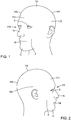
- Figures 1 and 2 show a wearer's head comprising a front region FR, right and left side regions RS, LS, a back region BR, and a top region TR.
- the front region FR includes a face F of the wearer, eyes E, a nose N and a mouth M of the wearer' face F, a chin C, a forehead FH.
- the right and left side regions RS, LS are located between the front region FR and the back region BR of the head and respectively include right and left temples and ears and right and left lateral parts of the head in right and left temporal bone areas of the head.
- the back region BR has a rear upper part and an occipital protuberance in a parietal bone area and occipital bone area.
- Figure 9 shows a hockey helmet 200 wearable on the wearer's head to protect the wearer's head when the helmet 200 is impacted (e.g., when the helmet 200 hits a board or an ice or other skating surface of a hockey rink or is struck by a puck or a hockey stick).
- the helmet 200 protects various regions of the wearer's head.
- the hockey helmet 200 comprises an outer shell with a front for facing at least partially of the forehead FH, a back for facing the back region BR of the wearer's head, right and left sides for respectively facing the right and left side regions RS, LS of the wearer's head, and a top for facing the top region TR of the wearer's head.
- the helmet 200 has an external surface and an internal surface that defines a cavity for receiving the wearer's head and contacts the wearer's head when the helmet 200 is worn.
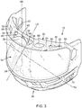
- Figures 3 to 6 show a face shield 10 for the hockey helmet 200.
- the face shield 10 has a front-back axis, a left-right axis, and a top-bottom axis that are respectively generally parallel to a dorsoventral axis, a dextrosinistral axis, and a cephalocaudal axis of the wearer when the helmet 200, with the face shield 10, is on the wearer's head. Since they are generally oriented longitudinally and transversally of the face shield 10, the front-back axis and the left-right axis can also be referred to as a longitudinal axis and a transversal axis, respectively.
- the top-bottom axis can also be referred to as a height axis.
- the face shield has a longitudinal axis LA, a transversal axis TA and a height axis HA as shown in Figure 3 .
- the face shield 10 may comprise any suitable polymer or glass material.
- the face shield comprises polymeric material having suitable impact-resistance.
- the polymeric material of the face shield 10 is polycarbonate.
- the face shield 10 may comprise any other suitable polymeric material and/or any other type of material in other examples of implementation (e.g., clear nylon, urethane-based material, polymethyl methacrylate, etc.).
- the face shield 10 has a transparent visor portion 12 for covering at least partially the wearer's forehead FH, the nose N and the eyes E of the wearer and the right and left sides the face F of the wearer. It is understood that the terms “transparent visor portion” covers a portion that is at least partially transparent, clear, translucid or light-transmitting to allow the wearer to properly see through the visor portion 12.
- the face shield 10 also comprises a bottom portion 14 for at least partially covering and encircling the mouth M and the chin C of the wearer, right and left side portions 16, 18 for covering the right and left sides of the wearer's face F and a top portion 20 for at least partially covering the forehead FH.
- the visor portion 12 has top and bottom edges 22, 24, an inner surface 26 that is concave and an outer surface 28 that is convex.
- the top portion 20 extends upwardly and rearwardly from the top edge 22 of the visor portion 12.
- the top portion 20 comprises a top edge portion 30 having a curvature for generally following a curvature of the front of the hockey helmet 200.
- the top edge portion 30 comprises a central bar 32 extending along the transversal axis TA and being located on right and left sides of the height axis HA.
- the top portion 20 also comprises first right and left bars 34, 36 extending upwardly and rearwardly on the right and left sides from the top edge 22 of the visor portion 12 and being each connected to the top edge portion 30.
- the top portion 20 comprises a central projection 38 between the right and left bars 34, 36 projecting upwardly and rearwardly from the top edge 22 of the visor portion 12.
- the central bar 32 and the central projection 38 define a transversal gap 40 therebetween.
- the central bar 32, the first right and left bars 34, 36 and the central projection 38 define right and left hollow spaces 42, 44 therebetween.
- the transversal gap 40 and the right and left hollow spaces 42, 44 together define a central aeration aperture 46 for facilitating air circulation and being sized to prevent a hockey stick blade or a puck from impacting the wearer's face.
- the central aeration aperture 46 is sized to prevent an object having a width of 150 mm (5.9 inches), a height of 50 mm (1.96 inches) and a thickness of 6 mm (0.24 inch) to enter in the central aeration aperture.
- the central aeration aperture 46 is sized to conform with certifications such as Certification CSA Z262.2-15.
- the central aeration aperture 46 may have any other shape in other examples of implementation as long as the top portion has a central projection with a transversal gap that allows movement of a connector (clip) along the central bar and as long as the central aeration aperture prevents a hockey stick blade or a puck from impacting the wearers face to conform with certifications such as Certification CSA Z262.2-15.
- the central aeration aperture 46 may also be beneficial for the wearer's vision.
- the central aeration aperture may make the face shield 10 less obstructive to the wearer's vision (e.g., when the wearer's head is down and his eyes are looking up).
- the central aeration aperture 46 renders the face shield 10 more airy, which may help in terms of wearer's fit, vision and ventilation.
- the top portion 20 also comprises right and left side ends 48, 50 joining together the top edge portion 30 and the visor portion 12 and second right and left bars 52, 54 extending upwardly and rearwardly from the top edge 22 of the visor portion 12 and being each connected to the top edge portion 30.
- the first right bar 34, the top edge portion 30, the top edge 22 of the visor portion 12 and the second right bar 52 define a first right aeration aperture 56 therebetween and the right side end 48
- the top edge portion 30, the top edge 22 of the visor portion 12 and the second right bar 52 define a second right aeration aperture 58 therebetween
- the first left bar 36, the top edge portion 30, the top edge 22 of the visor portion 12 and the second left bar 54 define a first left aeration aperture 60 therebetween and the left side end 50
- the top edge portion 30, the top edge 22 of the visor portion 12 and the second left bar 54 define a second left aeration aperture 62 therebetween.
- the bottom portion 14 comprises a bottom edge portion 64 extending downwardly and rearwardly for facing a bottom surface of the wearer's chin C, the bottom edge portion 64 comprising top and bottom edges 66, 68.
- the bottom portion 14 comprises a plurality of bottom bars extending downwardly and rearwardly from the bottom edge 24 of the visor portion 12 towards the top edge 66 of the bottom edge portion 64 and being connected to the bottom edge portion 64.
- the plurality of bottom bars comprises a first right bottom bar 70 located on the right side of the height axis HA and a first left bottom bar 72 located on the left side of the height axis HA.
- the first right bottom bar 70, the bottom edge 24 of the visor portion 12, the first left bottom bar 72 and the top edge 66 of the bottom edge portion 64 define therebetween a central bottom aeration aperture for facing the wearer's mouth.
- the bottom portion 14 comprises a plurality of slots 74 on each side for allowing passage of an adjustable strap.
- the bottom portion 14 also comprises a bottom transversal bar 76 extending from the right side portion 16 to the left side portion 18 along a curvature and being located between the bottom edge 24 of the visor portion 12 and the top edge 66 of the bottom edge portion 64.
- the first right and left bottom bars 70, 72 are each connected to the bottom transversal bar 76.
- the first right bottom bar 70, the bottom edge 24 of the visor portion 12, the first left bottom bar 72 and the bottom transversal bar 76 define therebetween a first central bottom aeration aperture 78 for facing the wearer's mouth and the first right bottom bar 70, the bottom transversal bar 76, the first left bottom bar 72 and the top edge 66 of the bottom edge portion 64 define therebetween a second central bottom aeration aperture 80 for facing the wearer's mouth.
- the first and second central bottom apertures 78, 80 have first and second sizes and the first size may be larger or similar than the second size.
- the plurality of bottom bars may comprise second and third right bars 82, 84 extending between the bottom edge 24 of the visor portion 12 and the top edge 66 of the bottom edge portion 64 and being each connected to the transversal bottom bar 76 and second and third left bars 86, 88 extending between the bottom edge 24 of the visor portion 12 and the top edge 66 of the bottom edge portion 64 and being each connected to the transversal bottom bar 76 for defining four additional aeration apertures 90, 92, 94, 96 on the right side and for additional aeration apertures 98, 100, 102, 104 on the left side.
- the face shield 10 also comprises right and left connectors 106, 108 for mounting the face shield 10 to the front of the hockey helmet 200.
- Each of the right and left connectors 106, 108 comprises a base portion 110 defining a substantially cylindrical aperture for receiving the central bar 32 and first and second legs 112, 114 extending from the base portion 110, the first and second legs 112, 114 having first and second holes 116, 118 for allowing passage of a screw 120 therethrough.
- the transversal gap 40 has a width that is sized to allow movement of the right and left connectors 106, 108 along the central bar 32 of the top portion 20.
- transversal gap 40 and the right and left hollow spaces 42, 44 allow movement of the right connector 106 towards the right bar 34 along a right distance of between 0.4 inch and 1.4 inches and movement of the left connector 108 towards the left bar 36 along a left distance of between 0.8 inch and 1.2 inches.
- the transversal gap 40 and right and left hollow spaces 42, 44 may allow movement of the right connector 106 towards the right bar 34 and movement of the left connector 108 towards the left bar 36 such that the holes of the right and left connectors 106, 108 are spaced apart of a distance between 0.8 inch and 2.5 inches.
- the front of the hockey helmet 200 has two mounting apertures for receiving two fasteners, each of the fastener having a base portion embedded into the pad assembly of the helmet and a post with a threaded aperture.
- the posts of the fasteners are located into the mounting apertures of the hockey helmet 200.
- the wearer may mount the right and left connectors 106, 108 on the central bar 32 of the top portion 20. Because of the transversal gap 40 between the central bar 32 and the central projection 38, the wearer may slide the connectors 106, 108 along the central bar 32 to adjust their position with respect to the mounting apertures. Moreover, because of the presence of the right and left hollow spaces 42, 44, the wearer may also turn the right connector 106 in the hollow space 42 and the left connector 108 in the hollow space 44.
- the transversal gap 40 and the right and left hollow spaces 42, 44 allow the wearer to insert at least partially his thumb or fingers in the central aeration aperture 46 to offer further mounting flexibilities or facilities.
- the wearer aligns the holes 116, 118 of the legs 112, 114 of one connector with one mounting aperture of the hockey helmet 200 and will then engage the screw 120 in the threaded aperture of the fastener for affixing the connector to the outer shell and for momentarily mounting the face shield to the hockey helmet 200.
- the wearer will afterwards align the holes 116, 118 of the legs 112, 114 of the other connector with the other mounting aperture and will then engage another screw 120 in the threaded aperture of the other fastener for affixing the other connector to the outer shell.
- the wearer can finalize mounting of the face shield 10 to the hockey helmet 200 by turning the screws 120 up to a point where the face shield 10 is solidly affixed to the hockey helmet 200.
- the face shield 10 may also comprise a chin pad 122 for engaging the chin C of the wearer.
Landscapes
- Helmets And Other Head Coverings (AREA)
Description
- The present invention relates to a face shield for a hockey helmet.
- A protective helmet is often used to protect a wearer's head during practice of a sport such as hockey, lacrosse, ringette, football and baseball. A protective helmet such as a hockey helmet sometimes comprises a visor, a face guard or face shield for protecting the wearer's face against impact with an object such as a sports implement (e.g. a stick, a stick blade, etc.), a puck, or any other object involved in hockey.
- One type of face guard is a full face shield that is adapted to cover the entire face of the wearer. The face shield has a transparent visor portion to be in front of the forehead, eyes and nose of the wearer, a bottom portion for covering and encircling the mouth and chin of the wearer, and a top portion with a top transversal bar. The bottom portion normally comprises a plurality of aeration apertures for allowing the wearer to breath properly. The bottom portion also normally comprises a plurality of slots on each side for allowing passage of an adjustable strap. The face shield is attached or pivotally mounted to the helmet at its top portion and the face shield is also coupled or mounted to the helmet via the adjustable strap.
- In order to mount the face shield to the helmet, right and left connectors can be used for mounting the face shield to the helmet. For instance, each of the right and left connectors comprises a base portion defining a cylindrical aperture and first and second legs extending from the base portion. The first and second legs have first and second holes for allowing passage of a screw therethrough. The connector may be a clip.
- As it is well known in the art, the front of the helmet has two mounting apertures for receiving two fasteners, each of the fastener having a base portion embedded into the pad assembly of the helmet and a post. The post has an outer surface and an inner surface defining a threaded aperture. The threaded aperture has a diameter and helical threads which are adapted to accept a threaded screw.
- The posts of the fasteners are located into the mounting apertures of the helmet outer shell. In use, the wearer may mount the right and left clips on the top transversal bar of the face shield top portion. Afterwards, the wearer will align the holes of the legs of one clip with one mounting aperture and will then engage a screw in the threaded aperture of the fastener for affixing the clip to the outer shell and for momentarily mounting the face shield to the helmet. The wearer will afterwards align the holes of the legs of the other clip with the other mounting aperture and will then engage another screw in the threaded aperture of the other fastener for affixing the other clip to the outer shell. Once both clips are in place, the wearer can finalize mounting of the face shield to the helmet.
- In a first variant of the prior art, the face shield top portion comprises a top longitudinal bar extending upwardly and rearwardly from the top edge of the visor portion and connecting a top transversal bar for defining two apertures on each side of the face shield. Each of the apertures is sized to prevent a hockey stick blade or a puck from impacting the wearer's face. Naturally, in this first variant, one clip cannot move or slide along the entire top transversal bar because of the presence of the top longitudinal bar. In a second variant of the prior art, the top portion may have an aperture between a top transversal bar and the top edge of the visor portion where the aperture has an oblong shape such that it occupies a transversal region as long as possible and a longitudinal region that is large enough for mounting the clip on the top transversal bar while also preventing a hockey stick blade or a puck from impacting the wearer's face. However, in this second variant, the wearer has less flexibility since he cannot turn the clip when the clip is mounted on the top transversal bar and the aperture of the second variant offers very limited access to the thumb and fingers.
-
US Patent 6,301,719 discloses a clip for releasably securing the transparent shield to the wire grid face protector. The clip comprises a retaining body adapted to be secured to a wire grid face protector at a predetermined location and on opposed sides of a sight opening formed in the wire grid face protector. The retaining body has a guide slot adapted to receive therein an attachment flange of a transparent shield. The outer wall of the body defines openings adapted to receive in abutting engagement a resilient, outwardly inclined tongue of the attachment flange. The transparent shield is disconnectable from the retaining body by inwardly depressing the tongue in the opening and by pulling the tongue out of the slot. -
US Patent 3,897,597 discloses a helmet and a face shield having a helmet portion generally covering the top, sides and back of the head of the wearer and a transparent face portion encircling the face and side regions of the wearer's head. The face portion is attached by a plurality of holding means on its opposite sides to the opposite side sections of the helmet. The face portion of the face shield has ventilating apertures to allow continuous circulation of air. The face portion also has mouth and chin guard disposed near its bottom edge. The helmet portion of the face shield has air circulation apertures aligned with longitudinally disposed padding means to ease ventilation of the wearer's head. - There is therefore a need for a face shield providing improvements in terms of facility of mounting the face shield to the helmet while still providing sufficient strength, impact resistance, and impact protection for the wearer. For instance, there is a need for an aperture offering more flexibility to the wearer by providing larger hollow spaces where the wearer can turn the clips, by allowing the wearer to insert at least partially his thumb and fingers in the aperture, while the aperture is nevertheless sized to prevent a hockey stick blade or a puck from impacting the wearer's face (to conform with certifications such as Certification CSA Z262.2-15).
- As embodied and broadly described herein, according to a broad aspect, the invention provides a face shield as defined in claims 1 to 16.
- As embodied and broadly described herein, according to a further broad aspect, the invention provides a face shield for a hockey helmet adapted to protect a head of a wearer, the helmet having an outer shell with a front for at least partially covering a forehead of the wearer's head, the face shield having a longitudinal axis, a transversal axis and a height axis, the face shield comprising: a transparent visor portion for at least partially covering the wearer's forehead, a nose and eyes of the wearer and right and left sides of a face of the wearer, wherein the visor portion has top and bottom edges, an inner surface that is concave and an outer surface that is convex; a bottom portion for at least partially covering and encircling a mouth and a chin of the wearer; right and left side portions for at least partially covering the right and left sides of the wearer's face; and a top portion extending upwardly and rearwardly from the top edge of the visor portion, wherein the top portion comprises: a top edge portion having a curvature for generally following a curvature of the front of the outer shell, the top edge portion comprising a central bar extending along the transversal axis and being located on right and left sides with respect to the height axis; right and left bars extending upwardly and rearwardly on the right and left sides from the top edge of the visor portion and being each connected to the top edge portion; and a central projection between the right and left bars projecting upwardly and rearwardly from the top edge of the visor portion; wherein the central bar and the central projection define a transversal gap therebetween; wherein the central bar, the right and left bars and the central projection define right and left hollow spaces therebetween; and wherein the transversal gap and the right and left hollow spaces together define a central aeration aperture being sized to prevent a hockey stick blade or puck from impacting the wearer's face.
- As embodied and broadly described herein, according to another broad aspect, the invention provides a face shield for a hockey helmet adapted to protect a head of a wearer, the helmet having an outer shell with a front for at least partially covering a forehead of the wearer's head, the face shield having a longitudinal axis, a transversal axis and a height axis, the face shield comprising: a transparent visor portion for at least partially covering the wearer's forehead, a nose and eyes of the wearer and right and left sides of a face of the wearer, wherein the visor portion has top and bottom edges, an inner surface that is concave and an outer surface that is convex; a bottom portion for at least partially covering and encircling a mouth and a chin of the wearer; right and left side portions for at least partially covering the right and left sides of the wearer's face; and a top portion extending upwardly and rearwardly from the top edge of the visor portion, wherein the top portion comprises: a top edge portion having a curvature for generally following a curvature of the front of the outer shell, the top edge portion comprising a central bar extending along the transversal axis and being located on right and left sides with respect to the height axis; right and left bars extending upwardly and rearwardly on the right and left sides from the top edge of the visor portion and being each connected to the top edge portion; and a central projection between the right and left bars projecting upwardly and rearwardly from the top edge of the visor portion; wherein the central bar and the central projection define a transversal gap therebetween; wherein the central bar, the right and left bars and the central projection define right and left hollow spaces therebetween; and wherein the transversal gap and the right and left hollow spaces together define a central aeration aperture being sized to prevent a hockey stick blade or puck from impacting the wearer's face and wherein one of the right and left hollow spaces allows a connector mounted on the central bar to pivot within the hollow space.
- As embodied and broadly described herein, according to further broad aspect, the invention provides a face shield for a hockey helmet adapted to protect a head of a wearer, the helmet having an outer shell with a front for at least partially covering a forehead of the wearer's head, the face shield having a longitudinal axis, a transversal axis and a height axis, the face shield comprising: a transparent visor portion for at least partially covering the wearer's forehead, a nose and eyes of the wearer and right and left sides of a face of the wearer, wherein the visor portion has top and bottom edges, an inner surface that is concave and an outer surface that is convex; a bottom portion for at least partially covering and encircling a mouth and a chin of the wearer, the bottom portion comprising a bottom edge portion extending downwardly and rearwardly for facing a bottom surface of the wearer's chin and wherein the bottom edge portion comprises top and bottom edges; right and left side portions for at least partially covering the right and left sides of the wearer's face; and a top portion extending upwardly and rearwardly from the top edge of the visor portion, wherein the top portion comprises: a top edge portion having a curvature for generally following a curvature of the front of the outer shell, the top edge portion comprising a central bar extending along the transversal axis and being located on right and left sides with respect to the height axis; right and left bars extending upwardly and rearwardly on the right and left sides from the top edge of the visor portion and being each connected to the top edge portion; and a central projection between the right and left bars projecting upwardly and rearwardly from the top edge of the visor portion; wherein the central bar and the central projection define a transversal gap therebetween; wherein the central bar, the right and left bars and the central projection define right and left hollow spaces therebetween; wherein the transversal gap and the right and left hollow spaces together define a central aeration aperture being sized to prevent a hockey stick blade or puck from impacting the wearer's face; and wherein the bottom portion comprises a right bottom bar located on the right side and a left bottom bar located on the left side, and wherein the right bottom bar, the bottom edge of the visor portion, the left bottom bar and the top edge of the bottom edge portion define therebetween a central bottom aeration aperture for facing the wearer's mouth.
- A detailed description of the embodiments of the present invention is provided herein below, by way of example only, with reference to the accompanying drawings, in which:
-
Figure 1 is a front side perspective view of a head of a wearer; -
Figure 2 is a side view of the wearer's head; -
Figure 3 is a front side perspective view of a face shield for a hockey helmet according to an embodiment; -
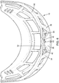
Figure 4 is a front view of the face shield ofFigure 3 ; -
Figure 5 is a side view of the face shield ofFigure 3 ; -
Figure 6 is a top inner view of the face shield ofFigure 3 ; -
Figure 7 is an enlarged fragmentary top view of a top portion of the face shield ofFigure 3 ; -
Figure 8 is an enlarged fragmentary front view of a top portion of the face shield with right and left connectors mounted on the central bar; and -
Figure 9 is a front side perspective view of the face shield ofFigure 3 with right and left connectors, right and left fasteners, and a hockey helmet. - In the drawings, embodiments of the invention are illustrated by way of examples. It is to be expressly understood that the description and drawings are only for the purpose of illustration and are an aid for understanding. They are not intended to be a definition of the limits of the invention.
- Before any variants, examples and preferred embodiments of the invention are explained in details, it is to be understood that the invention is not limited in its application to the details of construction and the arrangement of components set forth in the following description or illustrated in the drawings. The invention is capable of other embodiments and of being practiced or of being carried out in various ways.
- Moreover, it is to be understood that the phraseology and terminology used herein is for the purpose of description and should not be regarded as limiting. The use of "including," "comprising," or "having" and variations thereof herein is meant to encompass the items listed thereafter and equivalents thereof as well as additional items. Unless specified or limited otherwise, the terms "mounted," "connected," "supported," and "coupled" and variations thereof are used broadly and encompass both direct and indirect mountings, connections, supports, and couplings and are thus intended to include direct connections between two members without any other members interposed therebetween and indirect connections between members in which one or more other members are interposed therebetween. Further, "connected" and "coupled" are not restricted to physical or mechanical connections or couplings. Additionally, the words "lower", "upper", "upward", "down" and "downward" designate directions in the drawings to which reference is made. The terminology includes the words specifically mentioned above, derivatives thereof, and words or similar import.
-
Figures 1 and 2 show a wearer's head comprising a front region FR, right and left side regions RS, LS, a back region BR, and a top region TR. The front region FR includes a face F of the wearer, eyes E, a nose N and a mouth M of the wearer' face F, a chin C, a forehead FH. The right and left side regions RS, LS are located between the front region FR and the back region BR of the head and respectively include right and left temples and ears and right and left lateral parts of the head in right and left temporal bone areas of the head. The back region BR has a rear upper part and an occipital protuberance in a parietal bone area and occipital bone area. -
Figure 9 shows ahockey helmet 200 wearable on the wearer's head to protect the wearer's head when thehelmet 200 is impacted (e.g., when thehelmet 200 hits a board or an ice or other skating surface of a hockey rink or is struck by a puck or a hockey stick). Thehelmet 200 protects various regions of the wearer's head. - The
hockey helmet 200 comprises an outer shell with a front for facing at least partially of the forehead FH, a back for facing the back region BR of the wearer's head, right and left sides for respectively facing the right and left side regions RS, LS of the wearer's head, and a top for facing the top region TR of the wearer's head. Thehelmet 200 has an external surface and an internal surface that defines a cavity for receiving the wearer's head and contacts the wearer's head when thehelmet 200 is worn. -
Figures 3 to 6 show aface shield 10 for thehockey helmet 200. Theface shield 10 has a front-back axis, a left-right axis, and a top-bottom axis that are respectively generally parallel to a dorsoventral axis, a dextrosinistral axis, and a cephalocaudal axis of the wearer when thehelmet 200, with theface shield 10, is on the wearer's head. Since they are generally oriented longitudinally and transversally of theface shield 10, the front-back axis and the left-right axis can also be referred to as a longitudinal axis and a transversal axis, respectively. As it is generally oriented along a height of theface shield 10, the top-bottom axis can also be referred to as a height axis. Hence, the face shield has a longitudinal axis LA, a transversal axis TA and a height axis HA as shown inFigure 3 . - The
face shield 10 may comprise any suitable polymer or glass material. For example, in one embodiment, the face shield comprises polymeric material having suitable impact-resistance. More particularly, in this embodiment, the polymeric material of theface shield 10 is polycarbonate. Theface shield 10 may comprise any other suitable polymeric material and/or any other type of material in other examples of implementation (e.g., clear nylon, urethane-based material, polymethyl methacrylate, etc.). - The
face shield 10 has atransparent visor portion 12 for covering at least partially the wearer's forehead FH, the nose N and the eyes E of the wearer and the right and left sides the face F of the wearer. It is understood that the terms "transparent visor portion" covers a portion that is at least partially transparent, clear, translucid or light-transmitting to allow the wearer to properly see through thevisor portion 12. - The
face shield 10 also comprises abottom portion 14 for at least partially covering and encircling the mouth M and the chin C of the wearer, right and leftside portions top portion 20 for at least partially covering the forehead FH. - The
visor portion 12 has top andbottom edges inner surface 26 that is concave and anouter surface 28 that is convex. - The
top portion 20 extends upwardly and rearwardly from thetop edge 22 of thevisor portion 12. Thetop portion 20 comprises atop edge portion 30 having a curvature for generally following a curvature of the front of thehockey helmet 200. Thetop edge portion 30 comprises acentral bar 32 extending along the transversal axis TA and being located on right and left sides of the height axis HA. Thetop portion 20 also comprises first right and leftbars top edge 22 of thevisor portion 12 and being each connected to thetop edge portion 30. Moreover, thetop portion 20 comprises acentral projection 38 between the right and leftbars top edge 22 of thevisor portion 12. - As best seen in
Figure 7 and8 , thecentral bar 32 and thecentral projection 38 define atransversal gap 40 therebetween. Also, thecentral bar 32, the first right and leftbars central projection 38 define right and lefthollow spaces transversal gap 40 and the right and lefthollow spaces central aeration aperture 46 for facilitating air circulation and being sized to prevent a hockey stick blade or a puck from impacting the wearer's face. For instance, thecentral aeration aperture 46 is sized to prevent an object having a width of 150 mm (5.9 inches), a height of 50 mm (1.96 inches) and a thickness of 6 mm (0.24 inch) to enter in the central aeration aperture. Thecentral aeration aperture 46 is sized to conform with certifications such as Certification CSA Z262.2-15. - While the figures show a specific shape of the
central aeration aperture 46, is it understood that the central aeration aperture may have any other shape in other examples of implementation as long as the top portion has a central projection with a transversal gap that allows movement of a connector (clip) along the central bar and as long as the central aeration aperture prevents a hockey stick blade or a puck from impacting the wearers face to conform with certifications such as Certification CSA Z262.2-15. - In addition to facilitating ventilation or air circulation, the
central aeration aperture 46 may also be beneficial for the wearer's vision. For example, the central aeration aperture may make theface shield 10 less obstructive to the wearer's vision (e.g., when the wearer's head is down and his eyes are looking up). Thecentral aeration aperture 46 renders theface shield 10 more airy, which may help in terms of wearer's fit, vision and ventilation. - The
top portion 20 also comprises right and left side ends 48, 50 joining together thetop edge portion 30 and thevisor portion 12 and second right and leftbars top edge 22 of thevisor portion 12 and being each connected to thetop edge portion 30. - The first
right bar 34, thetop edge portion 30, thetop edge 22 of thevisor portion 12 and the secondright bar 52 define a firstright aeration aperture 56 therebetween and theright side end 48, thetop edge portion 30, thetop edge 22 of thevisor portion 12 and the secondright bar 52 define a secondright aeration aperture 58 therebetween. Similarly, the firstleft bar 36, thetop edge portion 30, thetop edge 22 of thevisor portion 12 and the secondleft bar 54 define a firstleft aeration aperture 60 therebetween and theleft side end 50, thetop edge portion 30, thetop edge 22 of thevisor portion 12 and the secondleft bar 54 define a secondleft aeration aperture 62 therebetween. - The
bottom portion 14 comprises abottom edge portion 64 extending downwardly and rearwardly for facing a bottom surface of the wearer's chin C, thebottom edge portion 64 comprising top andbottom edges - The
bottom portion 14 comprises a plurality of bottom bars extending downwardly and rearwardly from thebottom edge 24 of thevisor portion 12 towards thetop edge 66 of thebottom edge portion 64 and being connected to thebottom edge portion 64. - In one embodiment, the plurality of bottom bars comprises a first
right bottom bar 70 located on the right side of the height axis HA and a firstleft bottom bar 72 located on the left side of the height axis HA. The firstright bottom bar 70, thebottom edge 24 of thevisor portion 12, the firstleft bottom bar 72 and thetop edge 66 of thebottom edge portion 64 define therebetween a central bottom aeration aperture for facing the wearer's mouth. - In the embodiment shown in the figures, the
bottom portion 14 comprises a plurality ofslots 74 on each side for allowing passage of an adjustable strap. Thebottom portion 14 also comprises a bottomtransversal bar 76 extending from theright side portion 16 to theleft side portion 18 along a curvature and being located between thebottom edge 24 of thevisor portion 12 and thetop edge 66 of thebottom edge portion 64. The first right and left bottom bars 70, 72 are each connected to the bottomtransversal bar 76. - The first
right bottom bar 70, thebottom edge 24 of thevisor portion 12, the firstleft bottom bar 72 and the bottomtransversal bar 76 define therebetween a first centralbottom aeration aperture 78 for facing the wearer's mouth and the firstright bottom bar 70, the bottomtransversal bar 76, the firstleft bottom bar 72 and thetop edge 66 of thebottom edge portion 64 define therebetween a second centralbottom aeration aperture 80 for facing the wearer's mouth. The first and secondcentral bottom apertures - The plurality of bottom bars may comprise second and third
right bars bottom edge 24 of thevisor portion 12 and thetop edge 66 of thebottom edge portion 64 and being each connected to thetransversal bottom bar 76 and second and thirdleft bars bottom edge 24 of thevisor portion 12 and thetop edge 66 of thebottom edge portion 64 and being each connected to thetransversal bottom bar 76 for defining fouradditional aeration apertures additional aeration apertures - As seen in
Figures 8 and9 , theface shield 10 also comprises right and leftconnectors face shield 10 to the front of thehockey helmet 200. Each of the right and leftconnectors base portion 110 defining a substantially cylindrical aperture for receiving thecentral bar 32 and first andsecond legs base portion 110, the first andsecond legs second holes screw 120 therethrough. - The
transversal gap 40 has a width that is sized to allow movement of the right and leftconnectors central bar 32 of thetop portion 20. - Moreover, the
transversal gap 40 and the right and lefthollow spaces right connector 106 towards theright bar 34 along a right distance of between 0.4 inch and 1.4 inches and movement of theleft connector 108 towards theleft bar 36 along a left distance of between 0.8 inch and 1.2 inches. Thetransversal gap 40 and right and lefthollow spaces right connector 106 towards theright bar 34 and movement of theleft connector 108 towards theleft bar 36 such that the holes of the right and leftconnectors - The front of the
hockey helmet 200 has two mounting apertures for receiving two fasteners, each of the fastener having a base portion embedded into the pad assembly of the helmet and a post with a threaded aperture. The posts of the fasteners are located into the mounting apertures of thehockey helmet 200. - In use, the wearer may mount the right and left
connectors central bar 32 of thetop portion 20. Because of thetransversal gap 40 between thecentral bar 32 and thecentral projection 38, the wearer may slide theconnectors central bar 32 to adjust their position with respect to the mounting apertures. Moreover, because of the presence of the right and lefthollow spaces right connector 106 in thehollow space 42 and theleft connector 108 in thehollow space 44. Thetransversal gap 40 and the right and lefthollow spaces central aeration aperture 46 to offer further mounting flexibilities or facilities. - Afterwards, the wearer aligns the
holes legs hockey helmet 200 and will then engage thescrew 120 in the threaded aperture of the fastener for affixing the connector to the outer shell and for momentarily mounting the face shield to thehockey helmet 200. The wearer will afterwards align theholes legs screw 120 in the threaded aperture of the other fastener for affixing the other connector to the outer shell. Once both connectors are in place, the wearer can finalize mounting of theface shield 10 to thehockey helmet 200 by turning thescrews 120 up to a point where theface shield 10 is solidly affixed to thehockey helmet 200. Theface shield 10 may also comprise achin pad 122 for engaging the chin C of the wearer. - The above description of the embodiments should not be interpreted in a limiting manner since other variations, modifications and refinements are possible within the scope of the present invention. Accordingly, it should be understood that various features and aspects of the disclosed embodiments can be combined with or substituted for one another in order to form varying modes of the disclosed invention. The scope of the invention is defined in the appended claims.
Claims (16)
- A face shield (10) to be mounted to a hockey helmet (200) having an outer shell with a front for at least partially covering a forehead of a wearer's head, the face shield having a longitudinal axis, a transversal axis and a height axis, the face shield comprising: a transparent visor portion (12) for at least partially covering the wearer's forehead, a nose and eyes of the wearer and right and left sides of a face of the wearer, wherein the visor portion has top and bottom edges (22, 24), an inner surface (26) that is concave and an outer surface (28) that is convex; a bottom portion (14) for at least partially covering and encircling a mouth and a chin of the wearer; right and left side portions (16, 18) for at least partially covering the right and left sides of the wearer's face; and a top portion (20) extending upwardly and rearwardly from the top edge of the visor portion, wherein the top portion comprises: a top edge portion (30) having a curvature for generally following a curvature of the front of the outer shell, the top edge portion comprising a central bar (32) extending along the transversal axis and being located on right and left sides with respect to the height axis; right and left bars (34, 36) extending upwardly and rearwardly on the right and left sides from the top edge (22) of the visor portion and being each connected to the top edge portion; and a central projection (38) between the right and left bars projecting upwardly and rearwardly from the top edge of the visor portion; the face shield being characterized in that the central bar and the central projection define a transversal gap (40) therebetween; the central bar, the right and left bars and the central projection define right and left hollow spaces (42, 44) therebetween; and the transversal gap and the right and left hollow spaces together define a central aeration aperture (46) being sized to prevent a hockey stick blade or puck from impacting the wearer's face.
- The face shied of claim 1, wherein the transversal gap (40) is sized to allow movement of right and left connectors (106, 108) along the central bar.
- The face shield of claim 2, wherein the transversal gap (40) and right and left hollow spaces (42, 44) allow movement of the right connector (106) towards the right bar (34) along a right distance of between 1.016 cm (0.4 inch) and 3.556 cm (1.4 inches) and movement of the left connector (108) towards the left bar (36) along a left distance of between 2.54 cm (1 inch) and 5.08 cm (2 inches).
- The face shield of claim 3, wherein the right and left distances are each between 2.032 cm (0.8 inch) and 3.048 cm (1.2 inches).
- The face shield of claim 2, wherein the transversal gap (40) and right and left hollow spaces (42, 44) allow movement of a right connector (106) towards the right bar (34) and movement of a left connector (108) towards the left bar (36) such that holes (116, 118) of the right and left connectors are spaced apart of a distance between 2.032 cm (0.8 inch) and 6.35 cm (2.5 inches).
- The face shield of claim 1, comprising right and left connectors (106, 108) for mounting the face shield to the front of the outer shell, wherein each of the right and left connectors comprises a base portion (110) defining a substantially cylindrical aperture for receiving the central bar (32) and first and second legs (112, 114) extending from the base portion, the first and second legs having first and second holes (116, 118) for allowing passage of a screw (120) therethrough, and wherein the transversal gap (40) is sized to allow movement of the right and left connectors along the central bar.
- The face shield of claim 6, wherein the transversal gap (40) and right and left hollow spaces (42, 44) allow movement of the right connector (106) towards the right bar (34) along a right distance of between 1.016 cm (0.4 inch) and 3.556 cm (1.4 inches) and movement of the left connector (108) towards the left bar (36) along a left distance of between 0.4 inch and 1.4 inches.
- The face shield of claim 7, wherein the right and left distances are each between 2.032 cm (0.8 inch) and 3.048 cm (1.2 inches).
- The face shield of claim 6, wherein the transversal gap (40) and right and left hollow spaces (42, 44) allow movement of the right connector (106) towards the right bar (34) and movement of the left connector (108) towards the left bar (36) such that the holes (116, 118) of the right and left connectors are spaced apart of a distance between 2.032 cm (0.8 inch) and 6.35 cm (2.5 inches).
- The face shield of any one of claims 1 to 9, wherein the top portion (20) comprises right and left side ends (48, 50) joining together the top edge portion (30) and the visor portion (12), wherein the right side end, the top edge portion, the top edge and the right bar define a right aeration aperture (56; 58) therebetween and the left side end, the top edge portion, the top edge and the left bar define a left aeration aperture (60; 62) therebetween.
- The face shield of any one of claims 1 to 9, wherein the right and left bars are first right and left bars (34, 36) and wherein the top portion (20) comprises right and left side ends (48, 50) joining together the top edge portion (30) and the visor portion (12) and second right and left bars (52, 54) extending upwardly and rearwardly from the top edge (22) of the visor portion (12) and being each connected to the top edge portion (30), wherein the first right bar, the top edge portion, the top edge and the second right bar define a first right aeration aperture (56) therebetween, wherein the right side end, the top edge portion, the top edge and the second right bar define a second right aeration aperture (58) therebetween, wherein the first left bar, the top edge portion, the top edge and the second left bar define a first left aeration aperture (60) therebetween, and wherein the left side end, the top edge portion, the top edge and the second left bar define a second left aeration aperture (62) therebetween.
- The face shield of any one of claims 1 to 11, wherein the bottom portion (14) comprises a bottom edge portion (64) extending downwardly and rearwardly for at least partially facing a bottom surface of the wearer's chin and wherein the bottom edge portion comprises top and bottom edges (66, 68).
- The face shield of claim 12, wherein the bottom portion (14) comprises a plurality of bottom bars (70, 72, 82,84) extending downwardly and rearwardly from the bottom edge (24) of the visor portion (12) towards the top edge (66) of the bottom edge portion (64) and being each connected to the bottom edge portion.
- The face shield of claim 13, wherein the plurality of bottom bars comprise a right bottom bar (70) located on the right side and a left bottom bar (72) located on the left side, and wherein the right bottom bar, the bottom edge (24) of the visor portion (12), the left bottom bar and the top edge (66) of the bottom edge portion (64) define therebetween a central bottom aeration aperture (78; 80) for facing the wearer's mouth.
- The face shield of claim 13, wherein the plurality of bottom bars comprise a right bottom bar (70) located on the right side and a left bottom bar (72) located on the left side, wherein the bottom portion (14) comprises a bottom transversal bar (76) extending from the right side portion (16) to the left side portion (18) along a curvature and being located between the bottom edge (24) of the visor portion (12) and the top edge (66) of the bottom edge portion (64), wherein the right and left bottom bars (70, 72) are each connected to the bottom transversal bar, wherein the right bottom bar, the bottom edge of the visor portion, the left bottom bar and the bottom transversal bar define therebetween a first central bottom aeration aperture (78) for facing the wearer's mouth, and wherein the right bottom bar, the bottom transversal bar, the left bottom bar and the top edge of the bottom edge portion define therebetween a second central bottom aeration aperture (80) for facing the wearer's mouth.
- The face shield of claim 1, wherein one of the right and left hollow spaces (42, 44) allows a connector (106; 108) mounted on the central bar (32) to pivot within the hollow space.
Applications Claiming Priority (1)
| Application Number | Priority Date | Filing Date | Title |
|---|---|---|---|
| CA3015646A CA3015646C (en) | 2018-08-28 | 2018-08-28 | Face shield for a hockey helmet |
Publications (2)
| Publication Number | Publication Date |
|---|---|
| EP3616544A1 EP3616544A1 (en) | 2020-03-04 |
| EP3616544B1 true EP3616544B1 (en) | 2021-06-16 |
Family
ID=67658957
Family Applications (1)
| Application Number | Title | Priority Date | Filing Date |
|---|---|---|---|
| EP19191893.7A Active EP3616544B1 (en) | 2018-08-28 | 2019-08-15 | Face shield for a hockey helmet |
Country Status (2)
| Country | Link |
|---|---|
| EP (1) | EP3616544B1 (en) |
| CA (1) | CA3015646C (en) |
Family Cites Families (4)
| Publication number | Priority date | Publication date | Assignee | Title |
|---|---|---|---|---|
| US3897597A (en) * | 1972-05-31 | 1975-08-05 | Dale R Kasper | Face and head protector |
| US5815848A (en) * | 1995-07-14 | 1998-10-06 | Oakley, Inc. | Impact resistant face shield for sporting helmets |
| US6301719B1 (en) * | 2000-09-28 | 2001-10-16 | Itech Sport Products Inc. | Helmet face protector attachment system |
| US20070250992A1 (en) * | 2006-04-28 | 2007-11-01 | Brown Robin J | Batting helmet with adjustable face guard |
-
2018
- 2018-08-28 CA CA3015646A patent/CA3015646C/en active Active
-
2019
- 2019-08-15 EP EP19191893.7A patent/EP3616544B1/en active Active
Non-Patent Citations (1)
| Title |
|---|
| None * |
Also Published As
| Publication number | Publication date |
|---|---|
| EP3616544A1 (en) | 2020-03-04 |
| CA3015646C (en) | 2026-04-21 |
| CA3015646A1 (en) | 2020-02-28 |
Similar Documents
| Publication | Publication Date | Title |
|---|---|---|
| US11083239B2 (en) | Visor system for a protective sport helmet | |
| US5093936A (en) | Protective headgear and detachable face protector | |
| US6349416B1 (en) | Headguard-protective sports headband | |
| US5129108A (en) | Protective headgear and detachable face protector | |
| US3897597A (en) | Face and head protector | |
| US5267353A (en) | Face guard | |
| US5790988A (en) | Protective headgear | |
| US6938272B1 (en) | Protective sports helmet having a two-piece face cage | |
| US20180235300A1 (en) | Protective ball cap | |
| US20180338550A1 (en) | Face shield | |
| US20120216339A1 (en) | Helmet with Shell Having Raised Central Channel | |
| US20090031484A1 (en) | Protective face guard with transparent shield | |
| US8272070B2 (en) | Conical face shield | |
| US20090083891A1 (en) | Protective face mask | |
| US4168542A (en) | Helmet for racquet ball and other sports | |
| US20060117449A1 (en) | Protective eyewear | |
| WO2015009367A1 (en) | Protective ball cap | |
| US20070250992A1 (en) | Batting helmet with adjustable face guard | |
| US20030167558A1 (en) | Full coverage protective head gear | |
| CS238630B2 (en) | Sport helmet | |
| US20110078847A1 (en) | Protective eyewear | |
| US20080066208A1 (en) | Protective headwear | |
| US12290127B2 (en) | Systems and methods for fastening a faceguard to a helmet | |
| US20200068980A1 (en) | Face shield for a hockey helmet | |
| US20110145982A1 (en) | Eye protection for athletic uses |
Legal Events
| Date | Code | Title | Description |
|---|---|---|---|
| PUAI | Public reference made under article 153(3) epc to a published international application that has entered the european phase |
Free format text: ORIGINAL CODE: 0009012 |
|
| STAA | Information on the status of an ep patent application or granted ep patent |
Free format text: STATUS: THE APPLICATION HAS BEEN PUBLISHED |
|
| AK | Designated contracting states |
Kind code of ref document: A1 Designated state(s): AL AT BE BG CH CY CZ DE DK EE ES FI FR GB GR HR HU IE IS IT LI LT LU LV MC MK MT NL NO PL PT RO RS SE SI SK SM TR |
|
| AX | Request for extension of the european patent |
Extension state: BA ME |
|
| STAA | Information on the status of an ep patent application or granted ep patent |
Free format text: STATUS: REQUEST FOR EXAMINATION WAS MADE |
|
| 17P | Request for examination filed |
Effective date: 20200902 |
|
| RBV | Designated contracting states (corrected) |
Designated state(s): AL AT BE BG CH CY CZ DE DK EE ES FI FR GB GR HR HU IE IS IT LI LT LU LV MC MK MT NL NO PL PT RO RS SE SI SK SM TR |
|
| GRAP | Despatch of communication of intention to grant a patent |
Free format text: ORIGINAL CODE: EPIDOSNIGR1 |
|
| STAA | Information on the status of an ep patent application or granted ep patent |
Free format text: STATUS: GRANT OF PATENT IS INTENDED |
|
| INTG | Intention to grant announced |
Effective date: 20210113 |
|
| GRAS | Grant fee paid |
Free format text: ORIGINAL CODE: EPIDOSNIGR3 |
|
| GRAA | (expected) grant |
Free format text: ORIGINAL CODE: 0009210 |
|
| STAA | Information on the status of an ep patent application or granted ep patent |
Free format text: STATUS: THE PATENT HAS BEEN GRANTED |
|
| AK | Designated contracting states |
Kind code of ref document: B1 Designated state(s): AL AT BE BG CH CY CZ DE DK EE ES FI FR GB GR HR HU IE IS IT LI LT LU LV MC MK MT NL NO PL PT RO RS SE SI SK SM TR |
|
| REG | Reference to a national code |
Ref country code: GB Ref legal event code: FG4D |
|
| REG | Reference to a national code |
Ref country code: CH Ref legal event code: EP |
|
| REG | Reference to a national code |
Ref country code: DE Ref legal event code: R096 Ref document number: 602019005363 Country of ref document: DE |
|
| REG | Reference to a national code |
Ref country code: AT Ref legal event code: REF Ref document number: 1401578 Country of ref document: AT Kind code of ref document: T Effective date: 20210715 |
|
| REG | Reference to a national code |
Ref country code: SE Ref legal event code: TRGR |
|
| REG | Reference to a national code |
Ref country code: IE Ref legal event code: FG4D |
|
| REG | Reference to a national code |
Ref country code: LT Ref legal event code: MG9D |
|
| PG25 | Lapsed in a contracting state [announced via postgrant information from national office to epo] |
Ref country code: FI Free format text: LAPSE BECAUSE OF FAILURE TO SUBMIT A TRANSLATION OF THE DESCRIPTION OR TO PAY THE FEE WITHIN THE PRESCRIBED TIME-LIMIT Effective date: 20210616 Ref country code: HR Free format text: LAPSE BECAUSE OF FAILURE TO SUBMIT A TRANSLATION OF THE DESCRIPTION OR TO PAY THE FEE WITHIN THE PRESCRIBED TIME-LIMIT Effective date: 20210616 Ref country code: LT Free format text: LAPSE BECAUSE OF FAILURE TO SUBMIT A TRANSLATION OF THE DESCRIPTION OR TO PAY THE FEE WITHIN THE PRESCRIBED TIME-LIMIT Effective date: 20210616 Ref country code: BG Free format text: LAPSE BECAUSE OF FAILURE TO SUBMIT A TRANSLATION OF THE DESCRIPTION OR TO PAY THE FEE WITHIN THE PRESCRIBED TIME-LIMIT Effective date: 20210916 |
|
| REG | Reference to a national code |
Ref country code: AT Ref legal event code: MK05 Ref document number: 1401578 Country of ref document: AT Kind code of ref document: T Effective date: 20210616 |
|
| REG | Reference to a national code |
Ref country code: NL Ref legal event code: MP Effective date: 20210616 |
|
| PG25 | Lapsed in a contracting state [announced via postgrant information from national office to epo] |
Ref country code: NO Free format text: LAPSE BECAUSE OF FAILURE TO SUBMIT A TRANSLATION OF THE DESCRIPTION OR TO PAY THE FEE WITHIN THE PRESCRIBED TIME-LIMIT Effective date: 20210916 Ref country code: LV Free format text: LAPSE BECAUSE OF FAILURE TO SUBMIT A TRANSLATION OF THE DESCRIPTION OR TO PAY THE FEE WITHIN THE PRESCRIBED TIME-LIMIT Effective date: 20210616 Ref country code: RS Free format text: LAPSE BECAUSE OF FAILURE TO SUBMIT A TRANSLATION OF THE DESCRIPTION OR TO PAY THE FEE WITHIN THE PRESCRIBED TIME-LIMIT Effective date: 20210616 Ref country code: GR Free format text: LAPSE BECAUSE OF FAILURE TO SUBMIT A TRANSLATION OF THE DESCRIPTION OR TO PAY THE FEE WITHIN THE PRESCRIBED TIME-LIMIT Effective date: 20210917 |
|
| PG25 | Lapsed in a contracting state [announced via postgrant information from national office to epo] |
Ref country code: SM Free format text: LAPSE BECAUSE OF FAILURE TO SUBMIT A TRANSLATION OF THE DESCRIPTION OR TO PAY THE FEE WITHIN THE PRESCRIBED TIME-LIMIT Effective date: 20210616 Ref country code: NL Free format text: LAPSE BECAUSE OF FAILURE TO SUBMIT A TRANSLATION OF THE DESCRIPTION OR TO PAY THE FEE WITHIN THE PRESCRIBED TIME-LIMIT Effective date: 20210616 Ref country code: PT Free format text: LAPSE BECAUSE OF FAILURE TO SUBMIT A TRANSLATION OF THE DESCRIPTION OR TO PAY THE FEE WITHIN THE PRESCRIBED TIME-LIMIT Effective date: 20211018 Ref country code: RO Free format text: LAPSE BECAUSE OF FAILURE TO SUBMIT A TRANSLATION OF THE DESCRIPTION OR TO PAY THE FEE WITHIN THE PRESCRIBED TIME-LIMIT Effective date: 20210616 Ref country code: CZ Free format text: LAPSE BECAUSE OF FAILURE TO SUBMIT A TRANSLATION OF THE DESCRIPTION OR TO PAY THE FEE WITHIN THE PRESCRIBED TIME-LIMIT Effective date: 20210616 Ref country code: AT Free format text: LAPSE BECAUSE OF FAILURE TO SUBMIT A TRANSLATION OF THE DESCRIPTION OR TO PAY THE FEE WITHIN THE PRESCRIBED TIME-LIMIT Effective date: 20210616 Ref country code: ES Free format text: LAPSE BECAUSE OF FAILURE TO SUBMIT A TRANSLATION OF THE DESCRIPTION OR TO PAY THE FEE WITHIN THE PRESCRIBED TIME-LIMIT Effective date: 20210616 Ref country code: EE Free format text: LAPSE BECAUSE OF FAILURE TO SUBMIT A TRANSLATION OF THE DESCRIPTION OR TO PAY THE FEE WITHIN THE PRESCRIBED TIME-LIMIT Effective date: 20210616 Ref country code: SK Free format text: LAPSE BECAUSE OF FAILURE TO SUBMIT A TRANSLATION OF THE DESCRIPTION OR TO PAY THE FEE WITHIN THE PRESCRIBED TIME-LIMIT Effective date: 20210616 |
|
| PG25 | Lapsed in a contracting state [announced via postgrant information from national office to epo] |
Ref country code: PL Free format text: LAPSE BECAUSE OF FAILURE TO SUBMIT A TRANSLATION OF THE DESCRIPTION OR TO PAY THE FEE WITHIN THE PRESCRIBED TIME-LIMIT Effective date: 20210616 |
|
| REG | Reference to a national code |
Ref country code: DE Ref legal event code: R119 Ref document number: 602019005363 Country of ref document: DE |
|
| PG25 | Lapsed in a contracting state [announced via postgrant information from national office to epo] |
Ref country code: MC Free format text: LAPSE BECAUSE OF FAILURE TO SUBMIT A TRANSLATION OF THE DESCRIPTION OR TO PAY THE FEE WITHIN THE PRESCRIBED TIME-LIMIT Effective date: 20210616 |
|
| PLBE | No opposition filed within time limit |
Free format text: ORIGINAL CODE: 0009261 |
|
| REG | Reference to a national code |
Ref country code: BE Ref legal event code: MM Effective date: 20210831 |
|
| STAA | Information on the status of an ep patent application or granted ep patent |
Free format text: STATUS: NO OPPOSITION FILED WITHIN TIME LIMIT |
|
| PG25 | Lapsed in a contracting state [announced via postgrant information from national office to epo] |
Ref country code: DK Free format text: LAPSE BECAUSE OF FAILURE TO SUBMIT A TRANSLATION OF THE DESCRIPTION OR TO PAY THE FEE WITHIN THE PRESCRIBED TIME-LIMIT Effective date: 20210616 |
|
| 26N | No opposition filed |
Effective date: 20220317 |
|
| PG25 | Lapsed in a contracting state [announced via postgrant information from national office to epo] |
Ref country code: LU Free format text: LAPSE BECAUSE OF NON-PAYMENT OF DUE FEES Effective date: 20210815 Ref country code: AL Free format text: LAPSE BECAUSE OF FAILURE TO SUBMIT A TRANSLATION OF THE DESCRIPTION OR TO PAY THE FEE WITHIN THE PRESCRIBED TIME-LIMIT Effective date: 20210616 |
|
| PG25 | Lapsed in a contracting state [announced via postgrant information from national office to epo] |
Ref country code: IT Free format text: LAPSE BECAUSE OF FAILURE TO SUBMIT A TRANSLATION OF THE DESCRIPTION OR TO PAY THE FEE WITHIN THE PRESCRIBED TIME-LIMIT Effective date: 20210616 Ref country code: IE Free format text: LAPSE BECAUSE OF NON-PAYMENT OF DUE FEES Effective date: 20210815 Ref country code: FR Free format text: LAPSE BECAUSE OF NON-PAYMENT OF DUE FEES Effective date: 20210816 Ref country code: DE Free format text: LAPSE BECAUSE OF NON-PAYMENT OF DUE FEES Effective date: 20220301 Ref country code: BE Free format text: LAPSE BECAUSE OF NON-PAYMENT OF DUE FEES Effective date: 20210831 |
|
| REG | Reference to a national code |
Ref country code: CH Ref legal event code: PL |
|
| PG25 | Lapsed in a contracting state [announced via postgrant information from national office to epo] |
Ref country code: LI Free format text: LAPSE BECAUSE OF NON-PAYMENT OF DUE FEES Effective date: 20220831 Ref country code: CH Free format text: LAPSE BECAUSE OF NON-PAYMENT OF DUE FEES Effective date: 20220831 |
|
| PG25 | Lapsed in a contracting state [announced via postgrant information from national office to epo] |
Ref country code: CY Free format text: LAPSE BECAUSE OF FAILURE TO SUBMIT A TRANSLATION OF THE DESCRIPTION OR TO PAY THE FEE WITHIN THE PRESCRIBED TIME-LIMIT Effective date: 20210616 |
|
| PG25 | Lapsed in a contracting state [announced via postgrant information from national office to epo] |
Ref country code: HU Free format text: LAPSE BECAUSE OF FAILURE TO SUBMIT A TRANSLATION OF THE DESCRIPTION OR TO PAY THE FEE WITHIN THE PRESCRIBED TIME-LIMIT; INVALID AB INITIO Effective date: 20190815 |
|
| GBPC | Gb: european patent ceased through non-payment of renewal fee |
Effective date: 20230815 |
|
| PG25 | Lapsed in a contracting state [announced via postgrant information from national office to epo] |
Ref country code: MK Free format text: LAPSE BECAUSE OF FAILURE TO SUBMIT A TRANSLATION OF THE DESCRIPTION OR TO PAY THE FEE WITHIN THE PRESCRIBED TIME-LIMIT Effective date: 20210616 |
|
| PG25 | Lapsed in a contracting state [announced via postgrant information from national office to epo] |
Ref country code: GB Free format text: LAPSE BECAUSE OF NON-PAYMENT OF DUE FEES Effective date: 20230815 |
|
| PG25 | Lapsed in a contracting state [announced via postgrant information from national office to epo] |
Ref country code: GB Free format text: LAPSE BECAUSE OF NON-PAYMENT OF DUE FEES Effective date: 20230815 |
|
| PG25 | Lapsed in a contracting state [announced via postgrant information from national office to epo] |
Ref country code: MT Free format text: LAPSE BECAUSE OF FAILURE TO SUBMIT A TRANSLATION OF THE DESCRIPTION OR TO PAY THE FEE WITHIN THE PRESCRIBED TIME-LIMIT Effective date: 20210616 |
|
| PG25 | Lapsed in a contracting state [announced via postgrant information from national office to epo] |
Ref country code: TR Free format text: LAPSE BECAUSE OF FAILURE TO SUBMIT A TRANSLATION OF THE DESCRIPTION OR TO PAY THE FEE WITHIN THE PRESCRIBED TIME-LIMIT Effective date: 20210616 |
|
| PGFP | Annual fee paid to national office [announced via postgrant information from national office to epo] |
Ref country code: SE Payment date: 20251230 Year of fee payment: 7 |