EP3616519A1 - Antimicrobial air ducts - Google Patents
Antimicrobial air ducts Download PDFInfo
- Publication number
- EP3616519A1 EP3616519A1 EP19180724.7A EP19180724A EP3616519A1 EP 3616519 A1 EP3616519 A1 EP 3616519A1 EP 19180724 A EP19180724 A EP 19180724A EP 3616519 A1 EP3616519 A1 EP 3616519A1
- Authority
- EP
- European Patent Office
- Prior art keywords
- air
- refrigerator
- duct
- air duct
- storage compartment
- Prior art date
- Legal status (The legal status is an assumption and is not a legal conclusion. Google has not performed a legal analysis and makes no representation as to the accuracy of the status listed.)
- Granted
Links
Images





Classifications
-
- F—MECHANICAL ENGINEERING; LIGHTING; HEATING; WEAPONS; BLASTING
- F25—REFRIGERATION OR COOLING; COMBINED HEATING AND REFRIGERATION SYSTEMS; HEAT PUMP SYSTEMS; MANUFACTURE OR STORAGE OF ICE; LIQUEFACTION SOLIDIFICATION OF GASES
- F25D—REFRIGERATORS; COLD ROOMS; ICE-BOXES; COOLING OR FREEZING APPARATUS NOT OTHERWISE PROVIDED FOR
- F25D17/00—Arrangements for circulating cooling fluids; Arrangements for circulating gas, e.g. air, within refrigerated spaces
- F25D17/04—Arrangements for circulating cooling fluids; Arrangements for circulating gas, e.g. air, within refrigerated spaces for circulating air, e.g. by convection
- F25D17/042—Air treating means within refrigerated spaces
-
- A—HUMAN NECESSITIES
- A01—AGRICULTURE; FORESTRY; ANIMAL HUSBANDRY; HUNTING; TRAPPING; FISHING
- A01N—PRESERVATION OF BODIES OF HUMANS OR ANIMALS OR PLANTS OR PARTS THEREOF; BIOCIDES, e.g. AS DISINFECTANTS, AS PESTICIDES OR AS HERBICIDES; PEST REPELLANTS OR ATTRACTANTS; PLANT GROWTH REGULATORS
- A01N25/00—Biocides, pest repellants or attractants, or plant growth regulators, characterised by their forms, or by their non-active ingredients or by their methods of application, e.g. seed treatment or sequential application; Substances for reducing the noxious effect of the active ingredients to organisms other than pests
- A01N25/26—Biocides, pest repellants or attractants, or plant growth regulators, characterised by their forms, or by their non-active ingredients or by their methods of application, e.g. seed treatment or sequential application; Substances for reducing the noxious effect of the active ingredients to organisms other than pests in coated particulate form
- A01N25/28—Microcapsules or nanocapsules
-
- A—HUMAN NECESSITIES
- A01—AGRICULTURE; FORESTRY; ANIMAL HUSBANDRY; HUNTING; TRAPPING; FISHING
- A01N—PRESERVATION OF BODIES OF HUMANS OR ANIMALS OR PLANTS OR PARTS THEREOF; BIOCIDES, e.g. AS DISINFECTANTS, AS PESTICIDES OR AS HERBICIDES; PEST REPELLANTS OR ATTRACTANTS; PLANT GROWTH REGULATORS
- A01N55/00—Biocides, pest repellants or attractants, or plant growth regulators, containing organic compounds containing elements other than carbon, hydrogen, halogen, oxygen, nitrogen and sulfur
- A01N55/02—Biocides, pest repellants or attractants, or plant growth regulators, containing organic compounds containing elements other than carbon, hydrogen, halogen, oxygen, nitrogen and sulfur containing metal atoms
-
- A—HUMAN NECESSITIES
- A61—MEDICAL OR VETERINARY SCIENCE; HYGIENE
- A61L—METHODS OR APPARATUS FOR STERILISING MATERIALS OR OBJECTS IN GENERAL; DISINFECTION, STERILISATION OR DEODORISATION OF AIR; CHEMICAL ASPECTS OF BANDAGES, DRESSINGS, ABSORBENT PADS OR SURGICAL ARTICLES; MATERIALS FOR BANDAGES, DRESSINGS, ABSORBENT PADS OR SURGICAL ARTICLES
- A61L9/00—Disinfection, sterilisation or deodorisation of air
- A61L9/16—Disinfection, sterilisation or deodorisation of air using physical phenomena
- A61L9/18—Radiation
- A61L9/20—Ultraviolet radiation
- A61L9/205—Ultraviolet radiation using a photocatalyst or photosensitiser
-
- B—PERFORMING OPERATIONS; TRANSPORTING
- B01—PHYSICAL OR CHEMICAL PROCESSES OR APPARATUS IN GENERAL
- B01D—SEPARATION
- B01D53/00—Separation of gases or vapours; Recovering vapours of volatile solvents from gases; Chemical or biological purification of waste gases, e.g. engine exhaust gases, smoke, fumes, flue gases, aerosols
- B01D53/007—Separation of gases or vapours; Recovering vapours of volatile solvents from gases; Chemical or biological purification of waste gases, e.g. engine exhaust gases, smoke, fumes, flue gases, aerosols by irradiation
-
- B—PERFORMING OPERATIONS; TRANSPORTING
- B01—PHYSICAL OR CHEMICAL PROCESSES OR APPARATUS IN GENERAL
- B01D—SEPARATION
- B01D53/00—Separation of gases or vapours; Recovering vapours of volatile solvents from gases; Chemical or biological purification of waste gases, e.g. engine exhaust gases, smoke, fumes, flue gases, aerosols
- B01D53/34—Chemical or biological purification of waste gases
- B01D53/74—General processes for purification of waste gases; Apparatus or devices specially adapted therefor
- B01D53/86—Catalytic processes
- B01D53/88—Handling or mounting catalysts
- B01D53/885—Devices in general for catalytic purification of waste gases
-
- B—PERFORMING OPERATIONS; TRANSPORTING
- B01—PHYSICAL OR CHEMICAL PROCESSES OR APPARATUS IN GENERAL
- B01J—CHEMICAL OR PHYSICAL PROCESSES, e.g. CATALYSIS OR COLLOID CHEMISTRY; THEIR RELEVANT APPARATUS
- B01J23/00—Catalysts comprising metals or metal oxides or hydroxides, not provided for in group B01J21/00
- B01J23/08—Catalysts comprising metals or metal oxides or hydroxides, not provided for in group B01J21/00 of gallium, indium or thallium
-
- B—PERFORMING OPERATIONS; TRANSPORTING
- B01—PHYSICAL OR CHEMICAL PROCESSES OR APPARATUS IN GENERAL
- B01J—CHEMICAL OR PHYSICAL PROCESSES, e.g. CATALYSIS OR COLLOID CHEMISTRY; THEIR RELEVANT APPARATUS
- B01J23/00—Catalysts comprising metals or metal oxides or hydroxides, not provided for in group B01J21/00
- B01J23/38—Catalysts comprising metals or metal oxides or hydroxides, not provided for in group B01J21/00 of noble metals
- B01J23/48—Silver or gold
- B01J23/50—Silver
-
- B—PERFORMING OPERATIONS; TRANSPORTING
- B01—PHYSICAL OR CHEMICAL PROCESSES OR APPARATUS IN GENERAL
- B01J—CHEMICAL OR PHYSICAL PROCESSES, e.g. CATALYSIS OR COLLOID CHEMISTRY; THEIR RELEVANT APPARATUS
- B01J23/00—Catalysts comprising metals or metal oxides or hydroxides, not provided for in group B01J21/00
- B01J23/38—Catalysts comprising metals or metal oxides or hydroxides, not provided for in group B01J21/00 of noble metals
- B01J23/54—Catalysts comprising metals or metal oxides or hydroxides, not provided for in group B01J21/00 of noble metals combined with metals, oxides or hydroxides provided for in groups B01J23/02 - B01J23/36
- B01J23/66—Silver or gold
-
- B—PERFORMING OPERATIONS; TRANSPORTING
- B01—PHYSICAL OR CHEMICAL PROCESSES OR APPARATUS IN GENERAL
- B01J—CHEMICAL OR PHYSICAL PROCESSES, e.g. CATALYSIS OR COLLOID CHEMISTRY; THEIR RELEVANT APPARATUS
- B01J35/00—Catalysts, in general, characterised by their form or physical properties
- B01J35/30—Catalysts, in general, characterised by their form or physical properties characterised by their physical properties
- B01J35/39—Photocatalytic properties
-
- B—PERFORMING OPERATIONS; TRANSPORTING
- B01—PHYSICAL OR CHEMICAL PROCESSES OR APPARATUS IN GENERAL
- B01J—CHEMICAL OR PHYSICAL PROCESSES, e.g. CATALYSIS OR COLLOID CHEMISTRY; THEIR RELEVANT APPARATUS
- B01J35/00—Catalysts, in general, characterised by their form or physical properties
- B01J35/40—Catalysts, in general, characterised by their form or physical properties characterised by dimensions, e.g. grain size
- B01J35/45—Nanoparticles
-
- F—MECHANICAL ENGINEERING; LIGHTING; HEATING; WEAPONS; BLASTING
- F25—REFRIGERATION OR COOLING; COMBINED HEATING AND REFRIGERATION SYSTEMS; HEAT PUMP SYSTEMS; MANUFACTURE OR STORAGE OF ICE; LIQUEFACTION SOLIDIFICATION OF GASES
- F25D—REFRIGERATORS; COLD ROOMS; ICE-BOXES; COOLING OR FREEZING APPARATUS NOT OTHERWISE PROVIDED FOR
- F25D17/00—Arrangements for circulating cooling fluids; Arrangements for circulating gas, e.g. air, within refrigerated spaces
- F25D17/04—Arrangements for circulating cooling fluids; Arrangements for circulating gas, e.g. air, within refrigerated spaces for circulating air, e.g. by convection
- F25D17/06—Arrangements for circulating cooling fluids; Arrangements for circulating gas, e.g. air, within refrigerated spaces for circulating air, e.g. by convection by forced circulation
- F25D17/062—Arrangements for circulating cooling fluids; Arrangements for circulating gas, e.g. air, within refrigerated spaces for circulating air, e.g. by convection by forced circulation in household refrigerators
- F25D17/065—Arrangements for circulating cooling fluids; Arrangements for circulating gas, e.g. air, within refrigerated spaces for circulating air, e.g. by convection by forced circulation in household refrigerators with compartments at different temperatures
-
- F—MECHANICAL ENGINEERING; LIGHTING; HEATING; WEAPONS; BLASTING
- F25—REFRIGERATION OR COOLING; COMBINED HEATING AND REFRIGERATION SYSTEMS; HEAT PUMP SYSTEMS; MANUFACTURE OR STORAGE OF ICE; LIQUEFACTION SOLIDIFICATION OF GASES
- F25D—REFRIGERATORS; COLD ROOMS; ICE-BOXES; COOLING OR FREEZING APPARATUS NOT OTHERWISE PROVIDED FOR
- F25D17/00—Arrangements for circulating cooling fluids; Arrangements for circulating gas, e.g. air, within refrigerated spaces
- F25D17/04—Arrangements for circulating cooling fluids; Arrangements for circulating gas, e.g. air, within refrigerated spaces for circulating air, e.g. by convection
- F25D17/06—Arrangements for circulating cooling fluids; Arrangements for circulating gas, e.g. air, within refrigerated spaces for circulating air, e.g. by convection by forced circulation
- F25D17/067—Evaporator fan units
-
- F—MECHANICAL ENGINEERING; LIGHTING; HEATING; WEAPONS; BLASTING
- F25—REFRIGERATION OR COOLING; COMBINED HEATING AND REFRIGERATION SYSTEMS; HEAT PUMP SYSTEMS; MANUFACTURE OR STORAGE OF ICE; LIQUEFACTION SOLIDIFICATION OF GASES
- F25D—REFRIGERATORS; COLD ROOMS; ICE-BOXES; COOLING OR FREEZING APPARATUS NOT OTHERWISE PROVIDED FOR
- F25D17/00—Arrangements for circulating cooling fluids; Arrangements for circulating gas, e.g. air, within refrigerated spaces
- F25D17/04—Arrangements for circulating cooling fluids; Arrangements for circulating gas, e.g. air, within refrigerated spaces for circulating air, e.g. by convection
- F25D17/06—Arrangements for circulating cooling fluids; Arrangements for circulating gas, e.g. air, within refrigerated spaces for circulating air, e.g. by convection by forced circulation
- F25D17/08—Arrangements for circulating cooling fluids; Arrangements for circulating gas, e.g. air, within refrigerated spaces for circulating air, e.g. by convection by forced circulation using ducts
-
- A—HUMAN NECESSITIES
- A61—MEDICAL OR VETERINARY SCIENCE; HYGIENE
- A61L—METHODS OR APPARATUS FOR STERILISING MATERIALS OR OBJECTS IN GENERAL; DISINFECTION, STERILISATION OR DEODORISATION OF AIR; CHEMICAL ASPECTS OF BANDAGES, DRESSINGS, ABSORBENT PADS OR SURGICAL ARTICLES; MATERIALS FOR BANDAGES, DRESSINGS, ABSORBENT PADS OR SURGICAL ARTICLES
- A61L2209/00—Aspects relating to disinfection, sterilisation or deodorisation of air
- A61L2209/10—Apparatus features
- A61L2209/12—Lighting means
-
- B—PERFORMING OPERATIONS; TRANSPORTING
- B01—PHYSICAL OR CHEMICAL PROCESSES OR APPARATUS IN GENERAL
- B01D—SEPARATION
- B01D2255/00—Catalysts
- B01D2255/10—Noble metals or compounds thereof
- B01D2255/104—Silver
-
- B—PERFORMING OPERATIONS; TRANSPORTING
- B01—PHYSICAL OR CHEMICAL PROCESSES OR APPARATUS IN GENERAL
- B01D—SEPARATION
- B01D2255/00—Catalysts
- B01D2255/20—Metals or compounds thereof
- B01D2255/207—Transition metals
- B01D2255/20707—Titanium
-
- B—PERFORMING OPERATIONS; TRANSPORTING
- B01—PHYSICAL OR CHEMICAL PROCESSES OR APPARATUS IN GENERAL
- B01D—SEPARATION
- B01D2255/00—Catalysts
- B01D2255/20—Metals or compounds thereof
- B01D2255/207—Transition metals
- B01D2255/20715—Zirconium
-
- B—PERFORMING OPERATIONS; TRANSPORTING
- B01—PHYSICAL OR CHEMICAL PROCESSES OR APPARATUS IN GENERAL
- B01D—SEPARATION
- B01D2255/00—Catalysts
- B01D2255/20—Metals or compounds thereof
- B01D2255/209—Other metals
-
- B—PERFORMING OPERATIONS; TRANSPORTING
- B01—PHYSICAL OR CHEMICAL PROCESSES OR APPARATUS IN GENERAL
- B01D—SEPARATION
- B01D2255/00—Catalysts
- B01D2255/80—Type of catalytic reaction
- B01D2255/802—Photocatalytic
-
- B—PERFORMING OPERATIONS; TRANSPORTING
- B01—PHYSICAL OR CHEMICAL PROCESSES OR APPARATUS IN GENERAL
- B01D—SEPARATION
- B01D2257/00—Components to be removed
- B01D2257/70—Organic compounds not provided for in groups B01D2257/00 - B01D2257/602
- B01D2257/708—Volatile organic compounds V.O.C.'s
-
- B—PERFORMING OPERATIONS; TRANSPORTING
- B01—PHYSICAL OR CHEMICAL PROCESSES OR APPARATUS IN GENERAL
- B01D—SEPARATION
- B01D2257/00—Components to be removed
- B01D2257/91—Bacteria; Microorganisms
-
- F—MECHANICAL ENGINEERING; LIGHTING; HEATING; WEAPONS; BLASTING
- F24—HEATING; RANGES; VENTILATING
- F24F—AIR-CONDITIONING; AIR-HUMIDIFICATION; VENTILATION; USE OF AIR CURRENTS FOR SCREENING
- F24F8/00—Treatment, e.g. purification, of air supplied to human living or working spaces otherwise than by heating, cooling, humidifying or drying
- F24F8/20—Treatment, e.g. purification, of air supplied to human living or working spaces otherwise than by heating, cooling, humidifying or drying by sterilisation
- F24F8/24—Treatment, e.g. purification, of air supplied to human living or working spaces otherwise than by heating, cooling, humidifying or drying by sterilisation using sterilising media
-
- F—MECHANICAL ENGINEERING; LIGHTING; HEATING; WEAPONS; BLASTING
- F25—REFRIGERATION OR COOLING; COMBINED HEATING AND REFRIGERATION SYSTEMS; HEAT PUMP SYSTEMS; MANUFACTURE OR STORAGE OF ICE; LIQUEFACTION SOLIDIFICATION OF GASES
- F25D—REFRIGERATORS; COLD ROOMS; ICE-BOXES; COOLING OR FREEZING APPARATUS NOT OTHERWISE PROVIDED FOR
- F25D2317/00—Details or arrangements for circulating cooling fluids; Details or arrangements for circulating gas, e.g. air, within refrigerated spaces, not provided for in other groups of this subclass
- F25D2317/04—Treating air flowing to refrigeration compartments
- F25D2317/041—Treating air flowing to refrigeration compartments by purification
-
- F—MECHANICAL ENGINEERING; LIGHTING; HEATING; WEAPONS; BLASTING
- F25—REFRIGERATION OR COOLING; COMBINED HEATING AND REFRIGERATION SYSTEMS; HEAT PUMP SYSTEMS; MANUFACTURE OR STORAGE OF ICE; LIQUEFACTION SOLIDIFICATION OF GASES
- F25D—REFRIGERATORS; COLD ROOMS; ICE-BOXES; COOLING OR FREEZING APPARATUS NOT OTHERWISE PROVIDED FOR
- F25D2317/00—Details or arrangements for circulating cooling fluids; Details or arrangements for circulating gas, e.g. air, within refrigerated spaces, not provided for in other groups of this subclass
- F25D2317/04—Treating air flowing to refrigeration compartments
- F25D2317/041—Treating air flowing to refrigeration compartments by purification
- F25D2317/0417—Treating air flowing to refrigeration compartments by purification using an UV-lamp
Definitions
- the present device generally relates to antimicrobial air ducts for use in a refrigerator, and more specifically, to air ducts having one or more active surfaces used to remove particulate matter, kill microbes, and decompose volatile organic compounds in a refrigerator.
- One food preservation technique currently being used includes titanium dioxide (TiO 2 ) charged using a mercury lamp lighting system but due to the harmful effects of the mercury lamp integrated in this system, it could not meet the specifications or expectations for an antimicrobial application.
- the use of mercury in these types of UV lamp systems could be extremely dangerous due to health hazards and other handling issues associated with mercury.
- Another preservation and antimicrobial technique frequently used includes ozonizer systems that are directly integrated into the refrigerator. However, with time, significant decline in ozonizer performance is reported and their high cost makes these applications prohibitively expensive. Nano-misting techniques have also been studied but due to the harmful nature of the zinc and silver used in the applied nano-particles; these materials also did not meet consumer market requirements.
- a refrigerator includes a cabinet coupled to one or more doors forming a storage compartment and an air purifying duct system positioned in the storage compartment.
- the air purifying duct system includes an air duct in fluid communication with the storage compartment; a fan configured to circulate air between the storage compartment and air duct; a photocatalyst disposed on a portion of the interior surface; one or more LEDs positioned to project light across the air duct and onto the photocatalyst; and an air circulation path configured to direct pathogens within the storage compartment into the air duct using the fan.
- a refrigerator includes a cabinet coupled to one or more doors forming a storage compartment and an air purifying duct system positioned in the storage compartment.
- the air purifying duct system includes an air duct in fluid communication with the storage compartment; a fan configured to circulate air between the storage compartment and air duct; a nano-coating disposed on a portion of an interior surface of the air duct; and an air circulation path configured to direct pathogens within the storage compartment into the air duct using the fan.
- an air purifying duct system includes an air duct in fluid communication with a storage compartment; a fan configured to circulate air between the storage compartment and air duct; a nano-coating including titanium dioxide (TiO 2 ), silver (Ag), zirconium dioxide (ZrO 2 ), and/or gallium (Ga); and an air circulation path configured to direct pathogens within the storage compartment into the air duct using the fan and circulate purified air into the storage compartment.
- the air purifying duct system may additionally include a photocatalyst disposed on a portion of the interior surface and one or more LEDs positioned to project light across the air duct and onto the photocatalyst.
- the nano-coating may include titanium dioxide (TiO 2 ) and silver (Ag) or the nano-coating may include zirconium dioxide (ZrO 2 ) and gallium (Ga).
- the terms "upper,” “lower,” “right,” “left,” “rear,” “front,” “vertical,” “horizontal,” and derivatives thereof shall relate to the device as oriented in FIG. 1 .
- the device may assume various alternative orientations and step sequences, except where expressly specified to the contrary.
- the specific devices and processes illustrated in the attached drawings, and described in the following specification are simply exemplary embodiments of the inventive concepts defined in the appended claims. Hence, specific dimensions and other physical characteristics relating to the embodiments disclosed herein are not to be considered as limiting, unless the claims expressly state otherwise.
- the term "and/or,” when used in a list of two or more items, means that any one of the listed items can be employed by itself, or any combination of two or more of the listed items can be employed.
- the composition can contain A alone; B alone; C alone; A and B in combination; A and C in combination; B and C in combination; or A, B, and C in combination.
- the reference numeral 10 refers to a refrigerator.
- the refrigerator 10 includes a cabinet 14 coupled to one or more doors 18a, b forming a storage compartment 22 and an air purifying duct system 24 positioned in the storage compartment 22.
- the air purifying duct system 24 includes an air duct 26 in fluid communication with the storage compartment 22; a fan 30 coupled to an interior surface 34 of the air duct 26 wherein the fan 30 is configured to circulate air between the storage compartment 22 and air duct 26; a photocatalyst 38 disposed on a portion of the interior surface 34; one or more LEDs 42 positioned to project light across the air duct 26 and onto the photocatalyst 38; and an air circulation path 46 configured to direct pathogens, particulate matter, and/or airborne bacteria 50 within the storage compartment 22 into the air duct 26 using the fan 30 and circulate purified air into the storage compartment 22.
- the air purifying duct system 24 provides an antimicrobial technology for in-vitro time-dependent reduction of microbial populations after exposure to a nano-coating 54 and/or the photocatalyst 38 being exposed to UV and/or visible light from the LEDs 42.
- the coating and purification technology incorporated into this air purifying duct system 24 includes the nano-coating 54, photocatalyst 38, and/or LEDs 42 where each respective component can provide an efficient air treatment capability that may interact with the deoxyribonucleic acid (DNA) and/or trigger a cascade of other biological reactions in harmful bacteria responsible for the spoilage of food stored at low temperatures in refrigerators.
- DNA deoxyribonucleic acid
- the photocatalyst 38 may include a photocatalytic nanostructured titanium dioxide (TiO 2 ) film, coating, or membrane deposited using sol-gel.
- the nano-coating 54 may include a nanostructured film, coating, or membrane deposited using sol-gel.
- the sol-gel can be doped to impart the titanium dioxide (TiO 2 ) or other metal/metal oxide mixture as the photocatalyst 38 that may be activated using visible light and/or an ultraviolet wavelength less than 700 nanometers (e.g., 245-700 nanometer wavelengths and 375-380 nanometer wavelengths) using a 12 volt UV LED strip or panel 82 (see FIG. 4 ) is provided.
- the photocatalyst 38 may be activated using an ultraviolet wavelength less than about 400 nm and/or visible light ranging from about 400 nm to about 700 nm.
- FIGS. 1A-1D a variety of different refrigerator environments were studied to determine how bacteria and other particulate matter may be introduced into the storage compartment 22 of the refrigerator 10.
- Each of the refrigerators 10 is shown having the cabinet 14 with the storage compartment 22 enclosed by the cabinet 14 and the door 18, in particular, a first door 18a and a second door 18b.
- the introduction of bacterial contamination to the storage compartment 22 was accomplished by positioning a contaminated chicken breast 58 containing many different types of bacteria.
- the test environment provided in FIG. 1A demonstrated that the bacteria growing on the contaminated chicken breast 58 did not spread to or reach any of plurality of petri dishes 62 proving that refrigerator bacterial contamination is likely not due to food cross-contamination, except for direct food contact.
- the introduction of bacterial contamination to the storage compartment 22 was accomplished by circulating air from outside the refrigerator 10 by opening and closing the first and second refrigerator doors 18a, 18b.
- airborne bacteria 50 was introduced to the storage compartment 22 and was able to contact and grow in the petri dishes 62.
- the refrigerator 10 in FIG. 1B did not include any air purifying or circulation system.
- the test environment provided in FIG. 1B demonstrates that bacteria introduced into the refrigerator 10 and corresponding foodstuffs is likely determined by the introduction of airborne bacteria 50 during refrigerator door 18a, b opening and closing.
- FIG. 1C In the third test environment illustrated in FIG. 1C , the introduction of bacterial contamination to the storage compartment 22 was accomplished as described in FIG. 1B , by opening and closing the refrigerator doors 18a, 18b.
- the additional variable introduced in FIG. 1C includes a standard fan driven circulation system 64 using only a single fan assembly which is currently implemented in many refrigerators.
- the test environment provided in FIG. 1C demonstrated that the single fan circulation system had minimal to no noticeable effect on the airborne bacteria 50 introduced into the storage compartment 22 of the refrigerator 10.
- FIG. 1D a front isometric view of the refrigerator 10 having the air purifying duct system 24 according to some aspects of the disclosure is provided.
- the introduction of bacterial contamination to the storage compartment 22 was accomplished as described in FIGS. 1B and 1C , by opening and closing the refrigerator doors 18a, 18b.
- the refrigerator 10 in FIG. 1D additionally includes the air purifying duct system 24 equipped with the air duct 26, fan 30, and photocatalyst 38 where the photocatalyst 38 can be activated by at least one LED 42 (see FIG. 3A ).
- the photocatalyst 38 can be activated by an array of LEDs 42 and/or a plurality of LEDs 42.
- the test environment provided in FIG. 1D demonstrated that the combination of the air purifying system 24 using the photocatalyst 38 and/or nano-coating 54 are able to reduce bacterial contamination in the storage compartment 22.
- the coatings 78 used in the air purifying duct system 24 may be formed using the photocatalyst 38 and/or the nano-coating 54.
- the photocatalyst 38 and the nano-coating 54 may be distinguished from each other based on the use and/or need of LED 42 activation.
- the term "photocatalyst 38" is defined to include, but is not limited to, metals, metal oxides, metal blends, metal oxide blends, and/or metal and metal oxide blends that have one or more band gap energies that match or correspond to the photons emitted from the LEDs 42.
- nano-coating 54 is defined to include an antimicrobial surface including, but not limited to, metals, metal oxides, metal blends, metal oxide blends, and/or metal and metal oxide blends that inhibit, damage, and/or kill microorganisms including bacteria without the need or use of selected wavelengths of LED lighting.
- certain materials described herein and used in the coatings 78 may be considered both a photocatalyst 38 and/or a nano-coating 54.
- one or more duct intakes 66 may direct polluted air into the air ducts 26 of the air purifying duct system 24 (see FIG. 2A-B ) to be purified.
- the one or more duct intakes 66 may be positioned on opposing cabinet walls, proximate an outer edge portion of the cabinet 14, proximate a shelf, or a combination thereof.
- the opening and closing of refrigerator doors 18a, 18b can introduce airborne bacteria 50 and other related pathogens into the storage compartment 22 in high enough concentrations to be able to contact and grow in petri dishes 62.
- pathogens as used herein, is defined to include airborne bacteria 50, viruses, fungi, and/or molds.
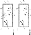
- the introduction and application of the air purifying duct system 24, including one or more light activated photocatalysts 38 (see FIG. 3A ) coupled to at least one duct wall 70 where the photocatalyst 38 can be activated using the plurality of LEDs 42 are able to reduce bacterial contamination in the storage compartment 22 by up to 70% when compared to the environments provided in FIGS. 1B and 1C .
- the circulated air of the air circulation path 46 exits the air ducts 26 of the air purifying duct system 24 through one or more duct exhausts 74 positioned in the storage compartment 22.
- the air circulation path 46 is directed into the air purifying duct system 24 through one or more duct intakes 66 by passing through a grate 68 and/or filter 72. As the air circulation path 46 passes through the duct intakes 66, the air continues through one or more air ducts 26 that may vary in numbers, shape, and positioning as determined by the design and application of the refrigerator 10. Bacterial contamination present in the circulated air of air circulation path 46 may be reduced or at least partially eliminated using the nano-coating 54 and/or photocatalyst 38 where the photocatalyst 38 may be activated using selected wavelengths projected by LEDs 42.
- the nano-coating 54 and/or photocatalyst 38 may be positioned and/or coupled to one or more duct walls 70 (see FIG. 3 ) of the air ducts 26.
- the circulated air of air circulation path 46 exits the air ducts 26 of the air purifying duct system 24 through one or more air duct exhausts 74 positioned in the storage compartment 22.
- the air purifying duct system 24 includes the nano-coating 54 but does not include the photocatalyst 38.
- the air purifying duct system 24 includes the photocatalyst 38 but does not include the nano-coating 54.
- the air purifying duct system 24 includes both the nano-coating 54 and the photocatalyst 38.
- the air duct intakes 66 of the air purifying duct system 24 may be positioned on opposing walls of the cabinet 14 in some aspects of the present disclosure. In other aspects, the air duct intakes 66 may be additionally or alternatively positioned against or in proximity to one or more refrigerator shelves to direct the air circulation path 46. In some aspects, the air purifying duct system 24 may be positioned flush with the one or more cabinet walls and/or refrigerator doors 18a, 18b (see FIG. 1D ). In other aspects, the air purifying duct system 24 may be positioned to stick out from the one or more cabinet walls and/or refrigerator doors 18a, 18b to form a ledge or protrusion.
- the cabinet 14 may be cutout or formed with an indentation to receive the air duct intakes 66 to form an even or flat surface on the cabinet walls.
- at least one air duct intake 66 is positioned in opposing cabinet walls.
- the one or more air duct intakes 66 may be positioned on a front lip or edge of the cabinet 14 configured to direct the air circulation path 46 (see FIG. 1D ) and corresponding fresh outside air into the air purifying duct system 24 before entering the cabinet 14.
- the air purifying duct system 24 may be positioned to circulate air between a refrigerator storage compartment and a freezer storage compartment.
- an evaporator (not shown) and a fan 30a may be positioned or located in the freezer compartment.
- the air purifying duct system 24, plenum, and/or multiflow may each be used to circulate air inside the freezer storage compartment and between the refrigerator and freezer storage compartments.
- the application of the photocatalyst 38 activated by the UV LEDs 42 is performed inside the air purifying duct system 24 that carry the air back and forth between the refrigerator and freezer storage compartments.
- the air circulation path 46 may be directed by the same fan 30a that circulates air through the evaporator to cool down the air using a single duct system for both air purification and air conditioning/cooling.
- the combination of two or more air duct intakes 66 are configured to provide the air circulation path 46 that directs the airborne bacteria 50, particulate matter 52, total solid particle (TSP), volatile organic compounds (VOCs), fungi, and/or molds simultaneously or contemporaneously into the air purifying duct system 24 using two or more circulation fans 30.
- the fans 30 direct the polluted air through the air duct 26 that may include the nano-coating 54 and/or the photocatalyst 38 irradiated by UV and/or visible light projected from the LEDs 42 to disinfect, filter, and/or clean the polluted air to circulate filtered air into the storage compartment 22 of the refrigerator 10.
- the use of just one air duct intake 66 may be unable to provide an air circulation path 46 that can effectively eliminate enough of the airborne bacteria 50.
- two or more air duct intakes 66 may be positioned on opposing first and second cabinet walls, positioned on the first and second doors 18a, 18b, or positioned on any two opposing interior surfaces where the two or more air duct intakes 66 work in a complementary manner to provide the improved air circulation path 46.
- the air circulation path 46 using two or more air duct intakes 66 may better direct the pathogens including airborne bacteria 50, particulate matter 52, TSP, volatile organic compounds (VOCs), fungi, and/or molds into the air purifying duct system 24 to be filtered.
- pathogens including airborne bacteria 50, particulate matter 52, TSP, volatile organic compounds (VOCs), fungi, and/or molds.
- the number of air duct intakes 66 and the number of air duct exhausts 74 may be limited to the number of circulation fans 30 incorporated into the air purifying duct system 24 based on the design and/or final air circulation properties desired for the refrigerator 10.
- the number of air duct intakes 66 may be two, three, four or more while the number of air duct exhausts 74 may include one, two, three, four, or more where the air duct intakes 66 and air duct exhausts 74 may be positioned with respect to each other in any combination.
- a main circulation fan 30a may be used in addition to or in place of the one or more fans 30 to provide the air circulation path 46.
- FIG. 2B a partially schematic fragmentary view of the air purifying duct system 24 is provided.
- airborne bacteria 50 and/or particulate matter 52 scattered throughout the storage compartment 22 are directed along the air circulation path 46 into at least one of the air duct intakes 66 of the air purifying duct system 24.
- the air circulation path 46 generally flows between the area of the storage assembly 22 and the one or more air purifying duct systems 24 using one or more (e.g. two, three, four) circulation fans 30 positioned in each air purifying duct system 24.
- FIG. 1B , 1C, and 1D the air introduced into the storage compartment 22 when opening the refrigerator doors 18a, 18b (see FIG.
- the air circulation path 46 generated by the one or more fans 30 direct the airborne bacteria 50 and/or particulate matter 52 in through air duct intake 66 to pass through the air duct 26 and out through the air duct exhaust 74.
- Any combination of interior surfaces 34 of the one or more air ducts 26, one or more fans 30, one or more air duct intakes 66, and/or one or more air duct exhausts 74 may be coupled to the photocatalyst 38 and/or nano-coating 54.
- one or more LEDs 42 see FIG.
- the photocatalyst 38 can project UV and/or visible light onto the photocatalysts 38 coupled to the interior surface 34 of the air ducts 26, fans 30, air duct intakes 66, and/or air duct exhausts 74.
- the photocatalyst 38 may be activated by the UV LED light, where the activated photocatalyst 38 can then kill and/or damage the airborne bacteria 50.
- the dead or damaged airborne bacteria 50 and/or particulate matter 52 may be circulated back into the storage compartment 22 in aspects where no filter is coupled to the air purifying duct system 24.
- the corresponding or resultant outlet purified air continues along the air circulation path 46 out through the air duct exhaust 74 and back into the storage compartment 22 of the cabinet 14.
- a filter 72 may be coupled and/or positioned in the air circulation path 46 to help remove the dead or damaged airborne bacteria 50 and/or particulate matter 70 from being circulated back into the storage compartment 22 of the cabinet 14.
- the filter 72 or filter membrane may be made from a polymer fiber, a glass fiber, a ceramic fiber, or a combination thereof.
- the polymer fiber may include polyethylene (PE), polypropylene (PP), polyester, polyamide, polyvinylpolypyrrolidone (PVPP), polystyrene, polyimides, naturally occurring polymers, thermoplastics, thermosets, or combinations thereof.
- the polymer fiber used to make the filter 72 is polyethylene, polypropylene, a blend of polyethylene, and/or a blend of polypropylene.
- the air purifying duct system 24 is able to purify the air and reduce pathogens when: 1) the doors 18 coupled to the refrigerator 10 are opened and closed to introduce new pathogens and particulate matter into the storage compartment 22; and/or 2) contaminated foodstuffs including meats and product release or introduce new pathogens and particulate matter into the storage compartment 22.
- the air purifying duct system 24 can completely circulate the entire volume of air in the storage compartment 2 to 50 times in a 24-hour period, 2 to 25 times in a 24-hour period, 2 to 15 times in a 24-hour period, or 3 to 5 times in a 24-hour period.
- the air duct 26 includes at least one duct wall 70 where the duct wall 70 may have any design or shape known by one skilled in the art.
- the duct wall 70 may be coupled to a coating 78 including the photocatalyst 38.
- An LED panel 82 may be operatively coupled to a portion of one or more of the duct walls 70 enabling the one or more LEDs 42 to project light onto the photocatalyst 38.
- the light-activated photocatalyst 38 and/or light 86 produced from the LEDs 42 may interact with the deoxyribonucleic acid (DNA) and/or trigger a cascade of other biological reactions in harmful bacteria 50 responsible for the spoilage of food stored at low temperatures in refrigerators.
- DNA deoxyribonucleic acid
- the photocatalyst 38 may include a UV and/or visible light activated photocatalyst including, but not limited to, titanium dioxide (TiO 2 ), zirconium dioxide (ZrO 2 ), silver (Ag), gallium (Ga), zinc oxide (ZnO), tin oxide (SnO 2 ), cesium oxide (CeO 2 ), zinc titanium dioxide (ZnTiO 2 ), copper titanium dioxide (CuTiO 2 ), silver titanium dioxide (AgTiO 2 ), iron titanium dioxide (FeTiO 2 ), or combinations thereof.
- a UV and/or visible light activated photocatalyst including, but not limited to, titanium dioxide (TiO 2 ), zirconium dioxide (ZrO 2 ), silver (Ag), gallium (Ga), zinc oxide (ZnO), tin oxide (SnO 2 ), cesium oxide (CeO 2 ), zinc titanium dioxide (ZnTiO 2 ), copper titanium dioxide (CuTiO 2 ), silver titanium
- the titanium dioxide (TiO 2 ), zirconium dioxide (ZrO 2 ), silver (Ag), gallium (Ga), zinc oxide (ZnO), tin oxide (SnO 2 ), cesium oxide (CeO 2 ), zinc titanium dioxide (ZnTiO 2 ), copper titanium dioxide (CuTiO 2 ), silver titanium dioxide (AgTiO 2 ), iron titanium dioxide (FeTiO 2 ), or combinations thereof used for the photocatalyst 38 may each be applied and/or used as nanoparticles.
- the photocatalyst's 38 titanium dioxide (TiO 2 ) nanoparticles, zirconium dioxide (ZrO 2 ) nanoparticles, silver (Ag) nanoparticles, gallium (Ga) nanoparticles, zinc oxide (ZnO) nanoparticles, tin oxide (SnO 2 ) nanoparticles, cesium oxide (CeO 2 ) nanoparticles, zinc titanium dioxide (ZnTiO 2 ) nanoparticles, copper titanium dioxide (CuTiO 2 ) nanoparticles, silver titanium dioxide (AgTiO 2 ) nanoparticles, iron titanium dioxide (FeTiO 2 ) nanoparticles, or combinations thereof may have a size from about 1 nm to about 100 nm, from about 1 nm to about 25 nm, from about 50 nm to about 100 nm, or from about 25 nm to about 75 nm.
- the photocatalyst 38 includes titanium dioxide (TiO 2 ). In other aspects, the photocatalyst 38 may include a mixture of titanium dioxide (TiO 2 ) and silver (Ag) or a mixture of zirconium dioxide (ZrO 2 ) and gallium (Ga). In still other aspects, the photocatalyst 38 may include a mixture of titanium dioxide (TiO 2 ), silver (Ag), zirconium dioxide (ZrO 2 ), and/or gallium (Ga).
- the photocatalyst 38 may be coated, coupled, and/or adsorbed onto the interior surface 34 of the air ducts 26, fans 30, air duct intakes 66, and/or air duct exhausts 74 using a variety of techniques including, for example, a sol gel approach.
- the interior surface 34 of the duct wall 70, air ducts 26, fans 30, air duct intakes 66, and/or air duct exhausts 74 includes a polyethylene material having a photocatalytic titanium dioxide (TiO 2 ) film deposited on its surface forming a nanostructured TiO 2 layer using sol gel.
- the interior surface 34 of the duct wall 70, air ducts 26, fans 30, air duct intakes 66, and/or air duct exhausts 74 may further or alternatively include an activated carbon and/or carbon black particles used to help filter polluted air circulated through the air purifying duct system 24.
- the TiO 2 or other photocatalyst 38 doped sol gel may include any sol gel or sol gel technique or method known in the art.
- the photocatalyst 38 may be operatively coupled to the interior surface 34 of the duct wall 70, air ducts 26, fans 30, air duct intakes 66, and/or air duct exhausts 74 using sol gel techniques or any other coating applications known by one skilled in the art (e.g., spin coating, solvent evaporation, spray coating, brushing, etc.).
- the air duct 26 includes at least one duct wall 70 where the duct wall 70 may have any design or shape known by one skilled in the art.
- the duct wall 70 may be coupled to a coating 78a including the nano-coating 54.
- the use of one or more LEDs 42 to project light onto the nano-coating 54 is not required.
- the nano-coating 54 itself, or without any photoactivation or excitation, is able to interact with the airborne bacteria 50 to trigger cell death and/or a cascade of other biological reactions to help prevent bacterial spoilage of food stored at low temperatures in refrigerators.
- the nano-coating 54 may include, but is not limited to, titanium dioxide (TiO 2 ), zirconium dioxide (ZrO 2 ), silver (Ag), gallium (Ga), zinc oxide (ZnO), tin oxide (SnO 2 ), cesium oxide (CeO 2 ), zinc titanium dioxide (ZnTiO 2 ), copper titanium dioxide (CuTiO 2 ), silver titanium dioxide (AgTiO 2 ), iron titanium dioxide (FeTiO 2 ), or combinations thereof.
- the nano-coating 54 includes a mixture of titanium dioxide (TiO 2 ), zirconium dioxide (ZrO 2 ), silver (Ag), and/or gallium (Ga).
- the titanium dioxide (TiO 2 ), zirconium dioxide (ZrO 2 ), silver (Ag), gallium (Ga), zinc oxide (ZnO), tin oxide (SnO 2 ), cesium oxide (CeO 2 ), zinc titanium dioxide (ZnTiO 2 ), copper titanium dioxide (CuTiO 2 ), silver titanium dioxide (AgTiO 2 ), iron titanium dioxide (FeTiO 2 ), or combinations thereof used for the nano-coating 54 may each be applied and/or used as nanoparticles.
- the nano-coating's 54 titanium dioxide (TiO 2 ) nanoparticles, zirconium dioxide (ZrO 2 ) nanoparticles, silver (Ag) nanoparticles, gallium (Ga) nanoparticles, zinc oxide (ZnO) nanoparticles, tin oxide (SnO 2 ) nanoparticles, cesium oxide (CeO 2 ) nanoparticles, zinc titanium dioxide (ZnTiO 2 ) nanoparticles, copper titanium dioxide (CuTiO 2 ) nanoparticles, silver titanium dioxide (AgTiO 2 ) nanoparticles, iron titanium dioxide (FeTiO 2 ) nanoparticles, or combinations thereof may each have a size from about 1 nm to about 100 nm, from about 1 nm to about 25 nm, from about 50 nm to about 100 nm, or from about 25 nm to about 75 nm.
- the nano-coating 54 may be coated, coupled, and/or adsorbed onto the interior surface 34 of the air ducts 26, fans 30, air duct intakes 66, and/or air duct exhausts 74 using a variety of techniques including, for example, a sol gel approach.
- the interior surface 34 of the duct wall 70, air ducts 26, fans 30, air duct intakes 66, and/or air duct exhausts 74 includes a polyethylene material having a nano-coating 54 film deposited on its surface forming a nanostructured layer using sol gel.
- the interior surface 34 of the duct wall 70, air ducts 26, fans 30, air duct intakes 66, and/or air duct exhausts 74 may include an activated carbon and/or carbon black particles used to help filter polluted air circulated through the air purifying duct system 24.
- the nano-coating 54 applied using a doped sol gel may include any sol gel or sol gel technique or method known in the art.
- the nano-coating 54 may be operatively coupled to the interior surface 34 of the duct wall 70, air ducts 26, fans 30, air duct intakes 66, and/or air duct exhausts 74 using sol gel techniques or any other coating applications known by one skilled in the art (e.g., spin coating, solvent evaporation, spray coating, brushing, etc.).
- the nano-coating 54 may include a mixture of titanium dioxide (TiO 2 ) and silver (Ag). In other aspects, the nano-coating 54 may include a mixture of zirconium dioxide (ZrO 2 ) and gallium (Ga). In still other aspects, the nano-coating 54 may include a mixture of titanium dioxide (TiO 2 ), silver (Ag), zirconium dioxide (ZrO 2 ), and/or gallium (Ga).
- the air purifying duct system 24 is able to provide at least a 50 % microbial reduction in one minute, at least a 50 % microbial reduction in three minutes, or at least a 50 % microbial reduction in ten minutes. In other aspects, the air purifying duct system 24 is able to provide at least a 60 % microbial reduction in one minute, at least a 60 % microbial reduction in three minutes, or at least a 60 % microbial reduction in ten minutes.
- the air purifying duct system 24 is able to provide at least a 70 % microbial reduction in one minute, at least a 70 % microbial reduction in three minutes, or at least a 70 % microbial reduction in ten minutes. In other aspects, the air purifying duct system 24 is able to provide at least an 80 % microbial reduction in one minute, at least an 80 % microbial reduction in three minutes, or at least an 80 % microbial reduction in ten minutes.
- the air purifying duct system 24 can reduce the VOCs in the storage compartment 22 of the refrigerator 10 by up to about 10 %, about 15 %, about 20 %, or about 25 % in less than 40 minutes, less than 60 minutes, less than 80 minutes, less than 100 minutes, or less than 120 minutes.
- the air purifying duct system 24 with a filter incorporated may be able to reduce the Total Solid Particulate (TSP) in the storage compartment 22 of the refrigerator 10 by up to about 10 %, about 15 %, about 20 %, about 25 %, about 30 %, about 35 %, about 40 %, or about 45 %, in at least 40 minutes, at least 60 minutes, at least 80 minutes, at least 100 minutes, or at least 120 minutes.
- TSP Total Solid Particulate
- the LED panel 82 includes one or more LEDs 42 positioned along the length of the LED panel 82 in a linear, zig-zagged, or any other spaced pattern.
- the one or more LEDs 42 may project visible light, UV-A light, UV-B light, UV-C light, or a combination thereof onto the photocatalyst 38.
- the LED panel 82 may be simplified by welding the device wiring 92 to LED conductive tracks 92a of the LED panel 82 and the circulation fans 30. Construction and wiring in this manner allows the assembled air purifying duct system 24 to be achieved using only six tin solders.
- one or more LED panels 82 may include LEDs 42 that emit UV light and/or visible light.
- the air purifying duct system 24 may include one LED panel 82 having white light LEDS for ambient lighting in the refrigerator 10 and a second LED panel (not shown) having UV LEDs used to activate the photocatalyst 38 coupled to the interior surface 34 of the air ducts 26, fans 30, air duct intakes 66, and/or air duct exhausts 74.
- the number of LED panels 82 and/or corresponding LEDs are not meant to be limiting and may be varied depending on the final design and corresponding functionality of the air purifying duct system 24 of the refrigerator 10.
- the LEDs 42 mounted on the LED panel 82 may be positioned or spaced apart from the photocatalyst 38 by from about 0.5 cm to about 4 cm or from about 1 cm to about 3 cm. In some aspects, the LEDs 42 may be spaced apart from the photocatalyst 38 by about 0.5 cm, about 1 cm, about 1.5 cm, about 2 cm, about 2.5 cm, about 3 cm, about 3.5 cm, or about 4 cm. In some aspects, the LED panel 82 and corresponding LEDs 42 may be mounted or positioned directly in front of or across from the duct wall 70 coupled to the photocatalyst 38. In some aspects, the LEDs 42 generate UV light that can kill bacteria without the use of the photocatalyst 38.
- the photocatalyst 38 is activated when exposed to UV and/or visible light generated and projected by the LEDs 42 where the activated photocatalyst 38 may be able to kill and/or damage the bacteria.
- the LEDs 42 can project a wavelength from about 100 nm to about 405 nm, from about 250 nm to about 405 nm, or from about 395 nm to about 405 nm.
- the plurality of LEDs 42 are UV-A LEDs that are positioned to project UV-A light on the photocatalyst 38 coupled to the interior surface 34 of the duct wall 70, air ducts 26, fans 30, air duct intakes 66, and/or air duct exhausts 74.
- the plurality of LEDs 42 are UV-B LEDs that are positioned to project UV-B light on the photocatalyst 38 coupled to the interior surface 34 of the duct wall 70, air ducts 26, fans 30, air duct intakes 66, and/or air duct exhausts 74.
- the plurality of LEDs 42 are UV-C LEDs that are positioned to project UV-C light on the photocatalyst 38 coupled to the interior surface 34 of the duct wall 70, air ducts 26, fans 30, air duct intakes 66, and/or air duct exhausts 74.
- the plurality of LEDs 42 are positioned to project UV-A light (315 nm to 400 nm), UV-B light (280 nm to 315 nm), UV-C light (100 nm to 280 nm), or a combination thereof on the photocatalyst 38 coupled to the interior surface 34 of the duct wall 70, air ducts 26, fans 30, air duct intakes 66, and/or air duct exhausts 74.
- the plurality of LEDs 42 are positioned to project UV-A light (315 nm to 400 nm) and UV-C light (100 nm to 280 nm) on the photocatalyst 38 coupled to the interior surface 34 of the duct wall 70, air ducts 26, fans 30, air duct intakes 66, and/or air duct exhausts 74.
- the LEDs 42 may project UV-A, UV-B, UV-C, or a combination of light thereof and/or visible light in the range from about 400 nm to about 700 nm.
- the LEDs 42 may project visible light in the range from about 400 nm to about 700 nm.
- the air purifying duct system 24 may include the fan 30 used to circulated polluted air in through the air duct intake 66 past the grate 68 and into the air duct 26.
- the photocatalyst 38 may be coupled to the interior surface 34 of the air ducts 26, fans 30, fan blades, air duct intakes 66, and/or air duct exhausts 74.
- the nano-coating 54 may be coupled to the interior surface 34 of the air ducts 26, fans 30, air duct intakes 66, and/or air duct exhausts 74. Additionally illustrated in FIG.
- the air purifying duct system 24 does not include the fan 30 but rather one or more filters 72 positioned in the air duct 26 but may rather rely on fan 30a (see FIG. 2A ) used to circulate cooled air from the evaporator used in the cooling cycle.
- the photocatalyst 38 and nano-coating 54 may be selectively coated on any combination of air ducts 26, fans 30, air duct intakes 66, and/or air duct exhausts 74.
- one or more fins 98 may be positioned and coupled on the interior surface 34 of the duct wall 70 in the air duct 26 to help manipulate or control the air circulation path 46 passing through the air purifying duct system 24.
- the plurality of fins 98 may be coated with the photocatalyst 38 and/or the nano-coating 54.
- the LED panel 82 includes one or more LEDS 42 positioned to direct UV and/or visible light onto the coating 78 of photocatalyst 38.
- One or more attachment members 102 may be molded or attached to the air duct 26 to couple the air purifying duct system 24 to the cabinet 14 of the refrigerator 10.
- Coupling members (not shown) used to couple the attachment members 102 to the cabinet 14 may include for example, but are not limited to, screws, bolts, nails, clips, snaps, and/or ties.
- Wiring 106 may be used to couple the LED panel to a controller 94.
- the controller 94 drives and communicates with the one or more circulation fans 30 and LED's 42 as triggered by a pre-programmed schedule or program, the opening and closing of the refrigerator doors 18, the detection of odor, bacteria 50, and/or particulate matter 52 using, for example, a bio-sensor, and/or other triggers or factors known by one skilled in the art.
- FIG. 5B provides a side view of the air purifying duct system 24 where the LED panel 82 may be coupled to the air duct 26 using one or more duct mounting members 110.
- the LED panel 82 illustrated in FIGS. 5A-5C is projected down the length of the air duct 26 but in some aspects (see FIGS. 3A and 3B ) the LED panel 82 may be positioned directly across one or more duct walls 70 to project selected wavelengths from the LEDs 42.
- the refrigerator 10 includes the cabinet 14 coupled to one or more doors 18 forming the storage compartment 22; the air duct 26 in fluid communication with the storage compartment 22; the fan 30 coupled to the interior surface 34 of the air duct 26 wherein the fan 30 is configured to circulate air between the storage compartment 22 and air duct 26; the nano-coating 54 disposed on a portion of the interior surface 34; and the air circulation path 46 configured to direct airborne bacteria 50 within the storage compartment 22 into the air duct 26 using the fan 30 and circulate purified air into the storage compartment 22.
- the air purifying duct system 24 includes the air duct 26 in fluid communication with the storage compartment 22; the fan 30 coupled to the interior surface 34 of the air duct 26 wherein the fan 30 is configured to circulate air between the storage compartment 22 and air duct 26; the nano-coating 54 including a mixture of titanium dioxide (TiO 2 ) and silver (Ag), a mixture of zirconium oxide (ZrO 2 ) and gallium (Ga), or a mixture of titanium dioxide (TiO 2 ), silver (Ag), zirconium oxide (ZrO 2 ), and gallium (Ga); and the air circulation path 46 configured to direct airborne bacteria 50 within the storage compartment 22 into the air duct 26 using the fan 30 and circulate purified air into the storage compartment 22.
- the nano-coating 54 including a mixture of titanium dioxide (TiO 2 ) and silver (Ag), a mixture of zirconium oxide (ZrO 2 ) and gallium (Ga), or a mixture of titanium dioxide (TiO 2 ), silver (
- the photocatalyst 38 may be used to replace or in addition to the nano-coating 54.
- the photocatalyst 38 may be disposed on a portion of the interior surface 34; one or more LEDs 42 positioned to project light across the air duct 26 and onto the photocatalyst 38
- the following examples and their corresponding data represent certain non-limiting examples of the air purifying duct system 24 used to effectively filter air in the storage compartment 22 of the refrigerator 10.
- the antibacterial refrigerator 10 and its corresponding air purifying duct system 24 using the photocatalyst 38 with LEDs 42 and/or the nano-coating 54 are designed to remove and/or destroy contaminants such as odor, toxic particles, and pathogens.
- contaminants such as odor, toxic particles, and pathogens.
- key substances that are typically removed through this air-treatment process include parasites, bacteria, algae, viruses, fungi, ethylene, and other food related chemical pollutants.
- the inoculum solution used in the experiments illustrated in FIG. 6A includes a microbial-loaded saline solution (50-70 ml) recovered during hand washing procedures.
- a microbial-loaded saline solution 50-70 ml recovered during hand washing procedures.
- the count of viable microorganisms was determined by means of the pour plate culture method.
- the inner compartment of a refrigerator (Whirlpool, BLFV8121W model) and the antibacterial device were first cleaned to remove any gross contamination using a quaternary benzyl ammonium disinfectant where the same cleaning procedure was performed on the storage compartment 22 in between each experiment.
- the antibacterial device was placed inside the refrigerator and the refrigerator was left to equilibrate at 40°C for at least 24 hours.
- the experiments included the nebulization of 450 microliters ( ⁇ L) of inoculum inside the refrigerator through a small hole made on the front wall of the refrigerator door ( ⁇ 1.2 cm).
- a test air filtration device 114 was switched on and kept on for a variety of different time periods (e.g., 1 min, 3 min, 10 min) after a microbial nebulization. Control experiments were carried out in the same conditions, but the test air filtration device 114 was not activated.
- the LB-agar petri dishes 62 were closed about 10 minutes after the microbial nebulization and incubated for the first 24 hrs at 37°C, and then for an additional 48 hrs at room temperature (RT). The number of viable microorganisms was then counted on LB-agar petri dishes. All of the experiments noted were performed in triplicate. Data was normalized with respect to the number of viable counts and control samples (CTRL, e.g., air filtration device turned off), considering the number of microorganisms in such condition as 100%. Results are expressed as mean ⁇ standard deviation (SD).
- CFU colony forming units
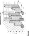
- the row of LP-agar petri dishes 62 positioned closest to the test air filtration device 114 contained the highest microbial population relative to Rows 1-3 while lowest microbial population was observed in the row furthest from the test air filtration device 114 (Row 1).
- the uniform difference and disparity in microbial populations based on the difference in distance between the corresponding rows and the test filtration device 114 supports the need for the air purifying duct system 24 as described herein.
- the viable CFU counts for each of the four rows were averaged and plotted against time as the test air filtration device 114 was operated to filter the storage compartment 22. Consistent with the data provided in FIG. 6B , when the filtration device was run for a longer period of time (e.g., 10 min vs. 3 min vs 1 min), the number of microorganisms decreased from about 50 to about 75% already after one minute and was generally maintained over the longer periods of time. Again consistent with the data provided in FIG. 6B , the decrease in CFU counted is dependent on the distance from the test air filtration device 114 where the decrease in CFU was more pronounced or greater at distances further away from the test air filtration device 114.
- a longer period of time e.g. 10 min vs. 3 min vs 1 min
- a refrigerator includes: a cabinet coupled to one or more doors forming a storage compartment; and an air purifying duct system positioned in the storage compartment, wherein the air purifying duct system includes: an air duct in fluid communication with the storage compartment; a fan configured to circulate air between the storage compartment and air duct; a photocatalyst disposed on a portion of the interior surface; one or more LEDs positioned to project light across the air duct and onto the photocatalyst; and an air circulation path configured to direct pathogens within the storage compartment into the air duct using the fan.
- the refrigerator according to the first aspect wherein the plurality of LEDs project visible light, UV-A light, UV-B light, UV-C light, or a combination thereof onto the photocatalyst.
- the refrigerator according to the first aspect or the second aspect wherein the photocatalyst is a coating containing a mixture of titanium dioxide nanoparticles (TiO 2 ) and silver nanoparticles (Ag).
- the refrigerator according to any one of the first aspect to the third aspect, wherein the photocatalyst is a coating containing a mixture of zirconium dioxide nanoparticles (ZrO 2 ) and gallium nanoparticles (Ga).
- the photocatalyst is a coating containing a mixture of zirconium dioxide nanoparticles (ZrO 2 ) and gallium nanoparticles (Ga).
- the refrigerator according to any one of the first aspect to the fourth aspect, wherein the photocatalyst includes a mixture of titanium dioxide nanoparticles (TiO 2 ), zirconium dioxide nanoparticles (ZrO 2 ), silver nanoparticles (Ag), and/or gallium nanoparticles (Ga).
- TiO 2 titanium dioxide nanoparticles
- ZrO 2 zirconium dioxide nanoparticles
- Ag silver nanoparticles
- Ga gallium nanoparticles
- the refrigerator according to any one of the first aspect to the fifth aspect, wherein the air duct includes one or more air duct intakes and one or more air duct exhausts.
- the refrigerator according to any one of the first aspect to the sixth aspect, wherein the air duct includes at least two air duct intakes positioned on opposing sidewalls and a plurality of air duct exhausts positioned along a back wall of the storage compartment.
- the refrigerator according to any one of the first aspect to the seventh aspect, wherein the air duct includes a plurality of fins coupled to the photocatalyst.
- the refrigerator according to any one of the first aspect to the eighth aspect, wherein the airborne bacteria in the storage compartment is reduced by at least 60% within one minute.
- the refrigerator according to any one of the first aspect to the ninth aspect, wherein the photocatalyst is additionally disposed on the one or more blades of the fan.
- a refrigerator includes: a cabinet coupled to one or more doors forming a storage compartment; an air duct in fluid communication with the storage compartment; a fan configured to circulate air between the storage compartment and air duct; a nano-coating disposed on a portion of an interior surface of the air duct; and an air circulation path configured to direct pathogens within the storage compartment into the air duct using the fan.
- the refrigerator according to the eleventh aspect further including: a photocatalyst disposed on a portion of the interior surface; and one or more LEDs positioned to project light across the air duct and onto the nano-coating.
- the refrigerator according to eleventh aspect or the twelfth aspect wherein the one or more LEDs project visible light, UV-A light, UV-B light, UV-C light, or a combination thereof onto the photocatalyst.
- the refrigerator according to any one of the eleventh aspect to the thirteenth aspect, wherein the nano-coating is a coating containing titanium dioxide nanoparticles (TiO 2 ) and silver nanoparticles (Ag).
- the refrigerator according to any one of the eleventh aspect to the fourteenth aspect, wherein the nano-coating is a coating containing zirconium dioxide nanoparticles (ZrO 2 ) and gallium nanoparticles (Ga).
- the nano-coating is a coating containing zirconium dioxide nanoparticles (ZrO 2 ) and gallium nanoparticles (Ga).
- the refrigerator according to any one of the eleventh aspect to the fifteenth aspect, wherein the nano-coating includes a mixture of titanium dioxide nanoparticles (TiO 2 ), zirconium dioxide nanoparticles (ZrO 2 ), silver nanoparticles (Ag), and/or gallium nanoparticles (Ga).
- TiO 2 titanium dioxide nanoparticles
- ZrO 2 zirconium dioxide nanoparticles
- Ag silver nanoparticles
- Ga gallium nanoparticles
- the refrigerator according to any one of the eleventh aspect to the sixteenth aspect, wherein the air duct includes a plurality of fins coupled to a nano-coating.
- an air purifying duct system includes: an air duct in fluid communication with a storage compartment; a fan configured to circulate air between the storage compartment and air duct; a nano-coating including titanium dioxide (TiO 2 ), silver (Ag), zirconium dioxide (ZrO 2 ), and/or gallium (Ga); and an air circulation path configured to direct pathogens within the storage compartment into the air duct using the fan and circulate purified air into the storage compartment.
- the refrigerator according to eighteenth aspect further including: a photocatalyst disposed on a portion of the interior surface; and one or more LEDs positioned to project light across the air duct and onto the nano-coating.
- the refrigerator according to the eighteenth aspect or the nineteenth aspect, wherein the air duct includes a plurality of fins coupled to the nano-coating.
- the term "coupled” in all of its forms, couple, coupling, coupled, etc. generally means the joining of two components (electrical or mechanical) directly or indirectly to one another. Such joining may be stationary in nature or movable in nature. Such joining may be achieved with the two components (electrical or mechanical) and any additional intermediate members being integrally formed as a single unitary body with one another or with the two components. Such joining may be permanent in nature or may be removable or releasable in nature unless otherwise stated.
- elements shown as integrally formed may be constructed of multiple parts or elements shown as multiple parts may be integrally formed, the operation of the interfaces may be reversed or otherwise varied, the length or width of the structures and/or members or connector or other elements of the system may be varied, the nature or number of adjustment positions provided between the elements may be varied.
- the elements and/or assemblies of the system may be constructed from any of a wide variety of materials that provide sufficient strength or durability, in any of a wide variety of colors, textures, and combinations. Accordingly, all such modifications are intended to be included within the scope of the present innovations. Other substitutions, modifications, changes, and omissions may be made in the design, operating conditions, and arrangement of the desired and other exemplary embodiments without departing from the spirit of the present innovations.
Landscapes
- Chemical & Material Sciences (AREA)
- Engineering & Computer Science (AREA)
- Chemical Kinetics & Catalysis (AREA)
- Health & Medical Sciences (AREA)
- Materials Engineering (AREA)
- Organic Chemistry (AREA)
- Life Sciences & Earth Sciences (AREA)
- Thermal Sciences (AREA)
- Mechanical Engineering (AREA)
- Physics & Mathematics (AREA)
- General Engineering & Computer Science (AREA)
- Combustion & Propulsion (AREA)
- General Health & Medical Sciences (AREA)
- Environmental & Geological Engineering (AREA)
- Analytical Chemistry (AREA)
- General Chemical & Material Sciences (AREA)
- Oil, Petroleum & Natural Gas (AREA)
- Toxicology (AREA)
- Environmental Sciences (AREA)
- Plant Pathology (AREA)
- Dentistry (AREA)
- Agronomy & Crop Science (AREA)
- Wood Science & Technology (AREA)
- Zoology (AREA)
- Pest Control & Pesticides (AREA)
- Public Health (AREA)
- Animal Behavior & Ethology (AREA)
- Epidemiology (AREA)
- Veterinary Medicine (AREA)
- Biomedical Technology (AREA)
- Cold Air Circulating Systems And Constructional Details In Refrigerators (AREA)
- Dispersion Chemistry (AREA)
Abstract
Description
- The present device generally relates to antimicrobial air ducts for use in a refrigerator, and more specifically, to air ducts having one or more active surfaces used to remove particulate matter, kill microbes, and decompose volatile organic compounds in a refrigerator.
- With the latest development of extra-large capacity refrigerators, there has been an emerging demand for highly robust antimicrobial technology such as air disinfection systems for food preservation and related features. Such systems are used to avoid the spoilage of food and produce stored in refrigerators for extended periods. Due to the unavailability of adequate antimicrobial technology, huge amounts of food, including produce, can go wasted even when stored in adequately low temperature refrigerators. Moreover, because of the increasing cost of commodities and food product costs, consumers are demanding efficient food storage technology for its longevity without compromise to its freshness.
- One food preservation technique currently being used includes titanium dioxide (TiO2) charged using a mercury lamp lighting system but due to the harmful effects of the mercury lamp integrated in this system, it could not meet the specifications or expectations for an antimicrobial application. In addition, the use of mercury in these types of UV lamp systems could be extremely dangerous due to health hazards and other handling issues associated with mercury. Another preservation and antimicrobial technique frequently used includes ozonizer systems that are directly integrated into the refrigerator. However, with time, significant decline in ozonizer performance is reported and their high cost makes these applications prohibitively expensive. Nano-misting techniques have also been studied but due to the harmful nature of the zinc and silver used in the applied nano-particles; these materials also did not meet consumer market requirements.
- Accordingly, the need for an efficient and affordable antimicrobial filtration system is required in the market place for consumers to better accommodate food safety and longer storage times for valuable foodstuffs.
- According to one aspect of the present disclosure, a refrigerator is provided. The refrigerator includes a cabinet coupled to one or more doors forming a storage compartment and an air purifying duct system positioned in the storage compartment. The air purifying duct system includes an air duct in fluid communication with the storage compartment; a fan configured to circulate air between the storage compartment and air duct; a photocatalyst disposed on a portion of the interior surface; one or more LEDs positioned to project light across the air duct and onto the photocatalyst; and an air circulation path configured to direct pathogens within the storage compartment into the air duct using the fan.
- According to another aspect of the present disclosure, a refrigerator is provided. The refrigerator includes a cabinet coupled to one or more doors forming a storage compartment and an air purifying duct system positioned in the storage compartment. The air purifying duct system includes an air duct in fluid communication with the storage compartment; a fan configured to circulate air between the storage compartment and air duct; a nano-coating disposed on a portion of an interior surface of the air duct; and an air circulation path configured to direct pathogens within the storage compartment into the air duct using the fan.
- According to yet another aspect of the present disclosure, an air purifying duct system is provided. The air purifying duct system includes an air duct in fluid communication with a storage compartment; a fan configured to circulate air between the storage compartment and air duct; a nano-coating including titanium dioxide (TiO2), silver (Ag), zirconium dioxide (ZrO2), and/or gallium (Ga); and an air circulation path configured to direct pathogens within the storage compartment into the air duct using the fan and circulate purified air into the storage compartment. In some aspects, the air purifying duct system may additionally include a photocatalyst disposed on a portion of the interior surface and one or more LEDs positioned to project light across the air duct and onto the photocatalyst. In some aspects, the nano-coating may include titanium dioxide (TiO2) and silver (Ag) or the nano-coating may include zirconium dioxide (ZrO2) and gallium (Ga).
- These and other aspects, objects, and features of the present disclosure will be understood and appreciated by those skilled in the art upon studying the following specification, claims, and appended drawings.
- In the drawings:
-
FIG. 1A is a front isometric view of a refrigerator having bacteria contaminated food; -
FIG. 1B is a front isometric view of a refrigerator having no food; -
FIG. 1C is a front isometric view of a refrigerator having a standard circulation fan; -
FIG. 1D is a front isometric view of a refrigerator having an air purifying duct system according to some aspects of the disclosure; -
FIG. 2A is an isolated isometric view of the air purifying duct system provided inFIG. 1D according to some aspects of the disclosure; -
FIG. 2B is an isolated isometric view of an air purifying duct system according to some aspects of the disclosure; -
FIG. 3A is a cross-sectional view of the air purifying duct system incorporating a photocatalyst taken along the line III-III inFIG. 2A ; -
FIG. 3B is a cross-sectional view of the air purifying duct system incorporating a nano-coating taken along the line III-III inFIG. 2A ; -
FIG. 4 is a front isometric view of a LED panel according to some aspects of the present disclosure; -
FIG. 5A is a top view of the air purifying duct system according to some aspects of the present disclosure; -
FIG. 5B is a side view of the air purifying duct system according to some aspects of the present disclosure; -
FIG. 5C is a top view of the air purifying duct system having a nano-coating according to some aspects of the present disclosure; -
FIG. 6A is a picture of the experimental set up of the nebulization of an inoculum solution using a filter assembly for fan filtration according to some aspects of the present disclosure; -
FIG. 6B is a distribution of microbial populations in a control using one filter assembly; and -
FIG. 6C provides averages of the distribution of microbial populations at various different times. - For purposes of description herein the terms "upper," "lower," "right," "left," "rear," "front," "vertical," "horizontal," and derivatives thereof shall relate to the device as oriented in
FIG. 1 . However, it is to be understood that the device may assume various alternative orientations and step sequences, except where expressly specified to the contrary. It is also to be understood that the specific devices and processes illustrated in the attached drawings, and described in the following specification, are simply exemplary embodiments of the inventive concepts defined in the appended claims. Hence, specific dimensions and other physical characteristics relating to the embodiments disclosed herein are not to be considered as limiting, unless the claims expressly state otherwise. - As used herein, the term "and/or," when used in a list of two or more items, means that any one of the listed items can be employed by itself, or any combination of two or more of the listed items can be employed. For example, if a composition is described as containing components A, B, and/or C, the composition can contain A alone; B alone; C alone; A and B in combination; A and C in combination; B and C in combination; or A, B, and C in combination.
- Referring to
FIGS. 1D-5B , thereference numeral 10 refers to a refrigerator. Therefrigerator 10 includes acabinet 14 coupled to one ormore doors 18a, b forming astorage compartment 22 and an airpurifying duct system 24 positioned in thestorage compartment 22. The airpurifying duct system 24 includes anair duct 26 in fluid communication with thestorage compartment 22; afan 30 coupled to an interior surface 34 of theair duct 26 wherein thefan 30 is configured to circulate air between thestorage compartment 22 andair duct 26; aphotocatalyst 38 disposed on a portion of the interior surface 34; one ormore LEDs 42 positioned to project light across theair duct 26 and onto thephotocatalyst 38; and anair circulation path 46 configured to direct pathogens, particulate matter, and/orairborne bacteria 50 within thestorage compartment 22 into theair duct 26 using thefan 30 and circulate purified air into thestorage compartment 22. - The air
purifying duct system 24 provides an antimicrobial technology for in-vitro time-dependent reduction of microbial populations after exposure to a nano-coating 54 and/or thephotocatalyst 38 being exposed to UV and/or visible light from theLEDs 42. The coating and purification technology incorporated into this airpurifying duct system 24 includes the nano-coating 54,photocatalyst 38, and/orLEDs 42 where each respective component can provide an efficient air treatment capability that may interact with the deoxyribonucleic acid (DNA) and/or trigger a cascade of other biological reactions in harmful bacteria responsible for the spoilage of food stored at low temperatures in refrigerators. In some aspects, thephotocatalyst 38 may include a photocatalytic nanostructured titanium dioxide (TiO2) film, coating, or membrane deposited using sol-gel. In other aspects, the nano-coating 54 may include a nanostructured film, coating, or membrane deposited using sol-gel. The sol-gel can be doped to impart the titanium dioxide (TiO2) or other metal/metal oxide mixture as thephotocatalyst 38 that may be activated using visible light and/or an ultraviolet wavelength less than 700 nanometers (e.g., 245-700 nanometer wavelengths and 375-380 nanometer wavelengths) using a 12 volt UV LED strip or panel 82 (seeFIG. 4 ) is provided. In some aspects, thephotocatalyst 38 may be activated using an ultraviolet wavelength less than about 400 nm and/or visible light ranging from about 400 nm to about 700 nm. - Referring now to
FIGS. 1A-1D , a variety of different refrigerator environments were studied to determine how bacteria and other particulate matter may be introduced into thestorage compartment 22 of therefrigerator 10. Each of therefrigerators 10 is shown having thecabinet 14 with thestorage compartment 22 enclosed by thecabinet 14 and thedoor 18, in particular, afirst door 18a and asecond door 18b. In the first test environment illustrated inFIG. 1A , the introduction of bacterial contamination to thestorage compartment 22 was accomplished by positioning a contaminatedchicken breast 58 containing many different types of bacteria. The test environment provided inFIG. 1A demonstrated that the bacteria growing on the contaminatedchicken breast 58 did not spread to or reach any of plurality ofpetri dishes 62 proving that refrigerator bacterial contamination is likely not due to food cross-contamination, except for direct food contact. - In the second test environment illustrated in
FIG. 1B , the introduction of bacterial contamination to thestorage compartment 22 was accomplished by circulating air from outside therefrigerator 10 by opening and closing the first andsecond refrigerator doors refrigerator doors airborne bacteria 50 was introduced to thestorage compartment 22 and was able to contact and grow in thepetri dishes 62. Therefrigerator 10 inFIG. 1B did not include any air purifying or circulation system. The test environment provided inFIG. 1B demonstrates that bacteria introduced into therefrigerator 10 and corresponding foodstuffs is likely determined by the introduction ofairborne bacteria 50 duringrefrigerator door 18a, b opening and closing. - In the third test environment illustrated in
FIG. 1C , the introduction of bacterial contamination to thestorage compartment 22 was accomplished as described inFIG. 1B , by opening and closing therefrigerator doors FIG. 1C includes a standard fan drivencirculation system 64 using only a single fan assembly which is currently implemented in many refrigerators. The test environment provided inFIG. 1C demonstrated that the single fan circulation system had minimal to no noticeable effect on theairborne bacteria 50 introduced into thestorage compartment 22 of therefrigerator 10. - In the fourth test environment illustrated in
FIG. 1D , a front isometric view of therefrigerator 10 having the airpurifying duct system 24 according to some aspects of the disclosure is provided. The introduction of bacterial contamination to thestorage compartment 22 was accomplished as described inFIGS. 1B and1C , by opening and closing therefrigerator doors refrigerator 10 inFIG. 1D additionally includes the airpurifying duct system 24 equipped with theair duct 26,fan 30, andphotocatalyst 38 where thephotocatalyst 38 can be activated by at least one LED 42 (seeFIG. 3A ). In some aspects, thephotocatalyst 38 can be activated by an array ofLEDs 42 and/or a plurality ofLEDs 42. The test environment provided inFIG. 1D demonstrated that the combination of theair purifying system 24 using thephotocatalyst 38 and/or nano-coating 54 are able to reduce bacterial contamination in thestorage compartment 22. - The coatings 78 (see
FIGS. 3A and 3B ) used in the airpurifying duct system 24 may be formed using thephotocatalyst 38 and/or the nano-coating 54. Thephotocatalyst 38 and the nano-coating 54 may be distinguished from each other based on the use and/or need ofLED 42 activation. As used herein, the term "photocatalyst 38" is defined to include, but is not limited to, metals, metal oxides, metal blends, metal oxide blends, and/or metal and metal oxide blends that have one or more band gap energies that match or correspond to the photons emitted from theLEDs 42. As used herein, the term "nano-coating 54" is defined to include an antimicrobial surface including, but not limited to, metals, metal oxides, metal blends, metal oxide blends, and/or metal and metal oxide blends that inhibit, damage, and/or kill microorganisms including bacteria without the need or use of selected wavelengths of LED lighting. In some aspects, certain materials described herein and used in thecoatings 78 may be considered both aphotocatalyst 38 and/or a nano-coating 54. - Still referring to
FIG. 1D , one ormore duct intakes 66 may direct polluted air into theair ducts 26 of the air purifying duct system 24 (seeFIG. 2A-B ) to be purified. In some aspects, the one ormore duct intakes 66 may be positioned on opposing cabinet walls, proximate an outer edge portion of thecabinet 14, proximate a shelf, or a combination thereof. As discussed inFIG. 1B , the opening and closing ofrefrigerator doors airborne bacteria 50 and other related pathogens into thestorage compartment 22 in high enough concentrations to be able to contact and grow inpetri dishes 62. The term "pathogens" as used herein, is defined to includeairborne bacteria 50, viruses, fungi, and/or molds. In some aspects, the introduction and application of the airpurifying duct system 24, including one or more light activated photocatalysts 38 (seeFIG. 3A ) coupled to at least oneduct wall 70 where thephotocatalyst 38 can be activated using the plurality ofLEDs 42, are able to reduce bacterial contamination in thestorage compartment 22 by up to 70% when compared to the environments provided inFIGS. 1B and1C . The circulated air of theair circulation path 46 exits theair ducts 26 of the airpurifying duct system 24 through one or more duct exhausts 74 positioned in thestorage compartment 22. - Referring now to
FIG. 2A , an isolated isometric view of the airpurifying duct system 24 according to some aspects of the disclosure is illustrated. Theair circulation path 46 is directed into the airpurifying duct system 24 through one ormore duct intakes 66 by passing through agrate 68 and/orfilter 72. As theair circulation path 46 passes through the duct intakes 66, the air continues through one ormore air ducts 26 that may vary in numbers, shape, and positioning as determined by the design and application of therefrigerator 10. Bacterial contamination present in the circulated air ofair circulation path 46 may be reduced or at least partially eliminated using the nano-coating 54 and/orphotocatalyst 38 where thephotocatalyst 38 may be activated using selected wavelengths projected byLEDs 42. The nano-coating 54 and/orphotocatalyst 38 may be positioned and/or coupled to one or more duct walls 70 (seeFIG. 3 ) of theair ducts 26. The circulated air ofair circulation path 46 exits theair ducts 26 of the airpurifying duct system 24 through one or more air duct exhausts 74 positioned in thestorage compartment 22. In some aspects, the airpurifying duct system 24 includes the nano-coating 54 but does not include thephotocatalyst 38. In other aspects, the airpurifying duct system 24 includes thephotocatalyst 38 but does not include the nano-coating 54. In still other aspects, the airpurifying duct system 24 includes both the nano-coating 54 and thephotocatalyst 38. - Still referring to
FIG. 2A , the air duct intakes 66 of the airpurifying duct system 24 may be positioned on opposing walls of thecabinet 14 in some aspects of the present disclosure. In other aspects, the air duct intakes 66 may be additionally or alternatively positioned against or in proximity to one or more refrigerator shelves to direct theair circulation path 46. In some aspects, the airpurifying duct system 24 may be positioned flush with the one or more cabinet walls and/orrefrigerator doors FIG. 1D ). In other aspects, the airpurifying duct system 24 may be positioned to stick out from the one or more cabinet walls and/orrefrigerator doors cabinet 14 may be cutout or formed with an indentation to receive the air duct intakes 66 to form an even or flat surface on the cabinet walls. In some aspects, at least oneair duct intake 66 is positioned in opposing cabinet walls. In other aspects, the one or more air duct intakes 66 may be positioned on a front lip or edge of thecabinet 14 configured to direct the air circulation path 46 (seeFIG. 1D ) and corresponding fresh outside air into the airpurifying duct system 24 before entering thecabinet 14. - Still referring to
FIG. 2A , in some aspects, the airpurifying duct system 24 may be positioned to circulate air between a refrigerator storage compartment and a freezer storage compartment. In some aspects, an evaporator (not shown) and afan 30a may be positioned or located in the freezer compartment. The airpurifying duct system 24, plenum, and/or multiflow may each be used to circulate air inside the freezer storage compartment and between the refrigerator and freezer storage compartments. In some aspects, the application of thephotocatalyst 38 activated by theUV LEDs 42 is performed inside the airpurifying duct system 24 that carry the air back and forth between the refrigerator and freezer storage compartments. In some aspects, theair circulation path 46 may be directed by thesame fan 30a that circulates air through the evaporator to cool down the air using a single duct system for both air purification and air conditioning/cooling. - As will be provided in more detail in the description for
FIGS. 6A-6C , the combination of two or more air duct intakes 66 are configured to provide theair circulation path 46 that directs theairborne bacteria 50,particulate matter 52, total solid particle (TSP), volatile organic compounds (VOCs), fungi, and/or molds simultaneously or contemporaneously into the airpurifying duct system 24 using two ormore circulation fans 30. Thefans 30 direct the polluted air through theair duct 26 that may include the nano-coating 54 and/or thephotocatalyst 38 irradiated by UV and/or visible light projected from theLEDs 42 to disinfect, filter, and/or clean the polluted air to circulate filtered air into thestorage compartment 22 of therefrigerator 10. As provided inFIGS. 1C ,6B , and6C , the use of just oneair duct intake 66 may be unable to provide anair circulation path 46 that can effectively eliminate enough of theairborne bacteria 50. In some aspects, two or more air duct intakes 66 may be positioned on opposing first and second cabinet walls, positioned on the first andsecond doors air circulation path 46. Theair circulation path 46 using two or more air duct intakes 66 may better direct the pathogens includingairborne bacteria 50,particulate matter 52, TSP, volatile organic compounds (VOCs), fungi, and/or molds into the airpurifying duct system 24 to be filtered. - In some aspects, the number of air duct intakes 66 and the number of air duct exhausts 74 may be limited to the number of
circulation fans 30 incorporated into the airpurifying duct system 24 based on the design and/or final air circulation properties desired for therefrigerator 10. In some aspects, the number of air duct intakes 66 may be two, three, four or more while the number of air duct exhausts 74 may include one, two, three, four, or more where the air duct intakes 66 and air duct exhausts 74 may be positioned with respect to each other in any combination. As illustrated inFIG. 2A , amain circulation fan 30a may be used in addition to or in place of the one ormore fans 30 to provide theair circulation path 46. - Referring now to
FIG. 2B , a partially schematic fragmentary view of the airpurifying duct system 24 is provided. As illustrated,airborne bacteria 50 and/orparticulate matter 52 scattered throughout the storage compartment 22 (seeFIG. 1D ) are directed along theair circulation path 46 into at least one of the air duct intakes 66 of the airpurifying duct system 24. Theair circulation path 46 generally flows between the area of thestorage assembly 22 and the one or more airpurifying duct systems 24 using one or more (e.g. two, three, four)circulation fans 30 positioned in each airpurifying duct system 24. As provided inFIG. 1B ,1C, and 1D , the air introduced into thestorage compartment 22 when opening therefrigerator doors FIG. 1D ) can includeairborne bacteria 50 and/orparticulate matter 52. Once therefrigerator doors corresponding storage compartment 22 are closed, theair circulation path 46 generated by the one ormore fans 30 direct theairborne bacteria 50 and/orparticulate matter 52 in throughair duct intake 66 to pass through theair duct 26 and out through theair duct exhaust 74. Any combination of interior surfaces 34 of the one ormore air ducts 26, one ormore fans 30, one or more air duct intakes 66, and/or one or more air duct exhausts 74 may be coupled to thephotocatalyst 38 and/or nano-coating 54. As theairborne bacteria 50 and/orparticulate matter 52 contact thephotocatalyst 38, one or more LEDs 42 (seeFIG. 3A ) can project UV and/or visible light onto thephotocatalysts 38 coupled to the interior surface 34 of theair ducts 26,fans 30, air duct intakes 66, and/or air duct exhausts 74. Thephotocatalyst 38 may be activated by the UV LED light, where the activatedphotocatalyst 38 can then kill and/or damage theairborne bacteria 50. The dead or damagedairborne bacteria 50 and/orparticulate matter 52 may be circulated back into thestorage compartment 22 in aspects where no filter is coupled to the airpurifying duct system 24. The corresponding or resultant outlet purified air continues along theair circulation path 46 out through theair duct exhaust 74 and back into thestorage compartment 22 of thecabinet 14. - In some aspects, a
filter 72 may be coupled and/or positioned in theair circulation path 46 to help remove the dead or damagedairborne bacteria 50 and/orparticulate matter 70 from being circulated back into thestorage compartment 22 of thecabinet 14. In some aspects, thefilter 72 or filter membrane may be made from a polymer fiber, a glass fiber, a ceramic fiber, or a combination thereof. The polymer fiber may include polyethylene (PE), polypropylene (PP), polyester, polyamide, polyvinylpolypyrrolidone (PVPP), polystyrene, polyimides, naturally occurring polymers, thermoplastics, thermosets, or combinations thereof. In some aspects, the polymer fiber used to make thefilter 72 is polyethylene, polypropylene, a blend of polyethylene, and/or a blend of polypropylene. - The air
purifying duct system 24 is able to purify the air and reduce pathogens when: 1) thedoors 18 coupled to therefrigerator 10 are opened and closed to introduce new pathogens and particulate matter into thestorage compartment 22; and/or 2) contaminated foodstuffs including meats and product release or introduce new pathogens and particulate matter into thestorage compartment 22. In some aspects, the airpurifying duct system 24 can completely circulate the entire volume of air in thestorage compartment 2 to 50 times in a 24-hour period, 2 to 25 times in a 24-hour period, 2 to 15 times in a 24-hour period, or 3 to 5 times in a 24-hour period. - Referring now to
FIG. 3A , a cross-sectional view of the airpurifying duct system 24 taken along the line III-III inFIG. 2A is provided according to some aspects of the present disclosure. Theair duct 26 includes at least oneduct wall 70 where theduct wall 70 may have any design or shape known by one skilled in the art. Theduct wall 70 may be coupled to acoating 78 including thephotocatalyst 38. AnLED panel 82 may be operatively coupled to a portion of one or more of theduct walls 70 enabling the one ormore LEDs 42 to project light onto thephotocatalyst 38. The light-activatedphotocatalyst 38 and/or light 86 produced from theLEDs 42 may interact with the deoxyribonucleic acid (DNA) and/or trigger a cascade of other biological reactions inharmful bacteria 50 responsible for the spoilage of food stored at low temperatures in refrigerators. - In some aspects, the
photocatalyst 38 may include a UV and/or visible light activated photocatalyst including, but not limited to, titanium dioxide (TiO2), zirconium dioxide (ZrO2), silver (Ag), gallium (Ga), zinc oxide (ZnO), tin oxide (SnO2), cesium oxide (CeO2), zinc titanium dioxide (ZnTiO2), copper titanium dioxide (CuTiO2), silver titanium dioxide (AgTiO2), iron titanium dioxide (FeTiO2), or combinations thereof. In some aspects, the titanium dioxide (TiO2), zirconium dioxide (ZrO2), silver (Ag), gallium (Ga), zinc oxide (ZnO), tin oxide (SnO2), cesium oxide (CeO2), zinc titanium dioxide (ZnTiO2), copper titanium dioxide (CuTiO2), silver titanium dioxide (AgTiO2), iron titanium dioxide (FeTiO2), or combinations thereof used for thephotocatalyst 38 may each be applied and/or used as nanoparticles. In some aspects, the photocatalyst's 38 titanium dioxide (TiO2) nanoparticles, zirconium dioxide (ZrO2) nanoparticles, silver (Ag) nanoparticles, gallium (Ga) nanoparticles, zinc oxide (ZnO) nanoparticles, tin oxide (SnO2) nanoparticles, cesium oxide (CeO2) nanoparticles, zinc titanium dioxide (ZnTiO2) nanoparticles, copper titanium dioxide (CuTiO2) nanoparticles, silver titanium dioxide (AgTiO2) nanoparticles, iron titanium dioxide (FeTiO2) nanoparticles, or combinations thereof may have a size from about 1 nm to about 100 nm, from about 1 nm to about 25 nm, from about 50 nm to about 100 nm, or from about 25 nm to about 75 nm. In some aspects, thephotocatalyst 38 includes titanium dioxide (TiO2). In other aspects, thephotocatalyst 38 may include a mixture of titanium dioxide (TiO2) and silver (Ag) or a mixture of zirconium dioxide (ZrO2) and gallium (Ga). In still other aspects, thephotocatalyst 38 may include a mixture of titanium dioxide (TiO2), silver (Ag), zirconium dioxide (ZrO2), and/or gallium (Ga). Thephotocatalyst 38 may be coated, coupled, and/or adsorbed onto the interior surface 34 of theair ducts 26,fans 30, air duct intakes 66, and/or air duct exhausts 74 using a variety of techniques including, for example, a sol gel approach. In some aspects, the interior surface 34 of theduct wall 70,air ducts 26,fans 30, air duct intakes 66, and/or air duct exhausts 74 includes a polyethylene material having a photocatalytic titanium dioxide (TiO2) film deposited on its surface forming a nanostructured TiO2 layer using sol gel. In other aspects, the interior surface 34 of theduct wall 70,air ducts 26,fans 30, air duct intakes 66, and/or air duct exhausts 74 may further or alternatively include an activated carbon and/or carbon black particles used to help filter polluted air circulated through the airpurifying duct system 24. The TiO2 orother photocatalyst 38 doped sol gel may include any sol gel or sol gel technique or method known in the art. Thephotocatalyst 38 may be operatively coupled to the interior surface 34 of theduct wall 70,air ducts 26,fans 30, air duct intakes 66, and/or air duct exhausts 74 using sol gel techniques or any other coating applications known by one skilled in the art (e.g., spin coating, solvent evaporation, spray coating, brushing, etc.). - Referring now to
FIG. 3B , a cross-sectional view of the airpurifying duct system 24 taken along the line III-III inFIG. 2A is provided according to other aspects of the present disclosure. Theair duct 26 includes at least oneduct wall 70 where theduct wall 70 may have any design or shape known by one skilled in the art. Theduct wall 70 may be coupled to a coating 78a including the nano-coating 54. In aspects where the airpurifying duct system 24 is coupled to the nano-coating 54, the use of one ormore LEDs 42 to project light onto the nano-coating 54 is not required. The nano-coating 54 itself, or without any photoactivation or excitation, is able to interact with theairborne bacteria 50 to trigger cell death and/or a cascade of other biological reactions to help prevent bacterial spoilage of food stored at low temperatures in refrigerators. - In some aspects, the nano-
coating 54 may include, but is not limited to, titanium dioxide (TiO2), zirconium dioxide (ZrO2), silver (Ag), gallium (Ga), zinc oxide (ZnO), tin oxide (SnO2), cesium oxide (CeO2), zinc titanium dioxide (ZnTiO2), copper titanium dioxide (CuTiO2), silver titanium dioxide (AgTiO2), iron titanium dioxide (FeTiO2), or combinations thereof. In some aspects, the nano-coating 54 includes a mixture of titanium dioxide (TiO2), zirconium dioxide (ZrO2), silver (Ag), and/or gallium (Ga). In some aspects, the titanium dioxide (TiO2), zirconium dioxide (ZrO2), silver (Ag), gallium (Ga), zinc oxide (ZnO), tin oxide (SnO2), cesium oxide (CeO2), zinc titanium dioxide (ZnTiO2), copper titanium dioxide (CuTiO2), silver titanium dioxide (AgTiO2), iron titanium dioxide (FeTiO2), or combinations thereof used for the nano-coating 54 may each be applied and/or used as nanoparticles. In some aspects, the nano-coating's 54 titanium dioxide (TiO2) nanoparticles, zirconium dioxide (ZrO2) nanoparticles, silver (Ag) nanoparticles, gallium (Ga) nanoparticles, zinc oxide (ZnO) nanoparticles, tin oxide (SnO2) nanoparticles, cesium oxide (CeO2) nanoparticles, zinc titanium dioxide (ZnTiO2) nanoparticles, copper titanium dioxide (CuTiO2) nanoparticles, silver titanium dioxide (AgTiO2) nanoparticles, iron titanium dioxide (FeTiO2) nanoparticles, or combinations thereof may each have a size from about 1 nm to about 100 nm, from about 1 nm to about 25 nm, from about 50 nm to about 100 nm, or from about 25 nm to about 75 nm. The nano-coating 54 may be coated, coupled, and/or adsorbed onto the interior surface 34 of theair ducts 26,fans 30, air duct intakes 66, and/or air duct exhausts 74 using a variety of techniques including, for example, a sol gel approach. In some aspects, the interior surface 34 of theduct wall 70,air ducts 26,fans 30, air duct intakes 66, and/or air duct exhausts 74 includes a polyethylene material having a nano-coating 54 film deposited on its surface forming a nanostructured layer using sol gel. In other aspects, the interior surface 34 of theduct wall 70,air ducts 26,fans 30, air duct intakes 66, and/or air duct exhausts 74 may include an activated carbon and/or carbon black particles used to help filter polluted air circulated through the airpurifying duct system 24. The nano-coating 54 applied using a doped sol gel may include any sol gel or sol gel technique or method known in the art. The nano-coating 54 may be operatively coupled to the interior surface 34 of theduct wall 70,air ducts 26,fans 30, air duct intakes 66, and/or air duct exhausts 74 using sol gel techniques or any other coating applications known by one skilled in the art (e.g., spin coating, solvent evaporation, spray coating, brushing, etc.). In some aspects, the nano-coating 54 may include a mixture of titanium dioxide (TiO2) and silver (Ag). In other aspects, the nano-coating 54 may include a mixture of zirconium dioxide (ZrO2) and gallium (Ga). In still other aspects, the nano-coating 54 may include a mixture of titanium dioxide (TiO2), silver (Ag), zirconium dioxide (ZrO2), and/or gallium (Ga). - In some aspects, the air
purifying duct system 24 is able to provide at least a 50 % microbial reduction in one minute, at least a 50 % microbial reduction in three minutes, or at least a 50 % microbial reduction in ten minutes. In other aspects, the airpurifying duct system 24 is able to provide at least a 60 % microbial reduction in one minute, at least a 60 % microbial reduction in three minutes, or at least a 60 % microbial reduction in ten minutes. In still other aspects, the airpurifying duct system 24 is able to provide at least a 70 % microbial reduction in one minute, at least a 70 % microbial reduction in three minutes, or at least a 70 % microbial reduction in ten minutes. In other aspects, the airpurifying duct system 24 is able to provide at least an 80 % microbial reduction in one minute, at least an 80 % microbial reduction in three minutes, or at least an 80 % microbial reduction in ten minutes. - In some aspects, the air
purifying duct system 24 can reduce the VOCs in thestorage compartment 22 of therefrigerator 10 by up to about 10 %, about 15 %, about 20 %, or about 25 % in less than 40 minutes, less than 60 minutes, less than 80 minutes, less than 100 minutes, or less than 120 minutes. In some aspects, the airpurifying duct system 24 with a filter incorporated may be able to reduce the Total Solid Particulate (TSP) in thestorage compartment 22 of therefrigerator 10 by up to about 10 %, about 15 %, about 20 %, about 25 %, about 30 %, about 35 %, about 40 %, or about 45 %, in at least 40 minutes, at least 60 minutes, at least 80 minutes, at least 100 minutes, or at least 120 minutes. - Referring now to
FIG. 4 , a front isometric view of theLED panel 82 is provided. TheLED panel 82 includes one ormore LEDs 42 positioned along the length of theLED panel 82 in a linear, zig-zagged, or any other spaced pattern. The one ormore LEDs 42 may project visible light, UV-A light, UV-B light, UV-C light, or a combination thereof onto thephotocatalyst 38. TheLED panel 82 may be simplified by welding thedevice wiring 92 to LEDconductive tracks 92a of theLED panel 82 and thecirculation fans 30. Construction and wiring in this manner allows the assembled airpurifying duct system 24 to be achieved using only six tin solders. In some aspects, one ormore LED panels 82 may includeLEDs 42 that emit UV light and/or visible light. For example, in some aspects, the airpurifying duct system 24 may include oneLED panel 82 having white light LEDS for ambient lighting in therefrigerator 10 and a second LED panel (not shown) having UV LEDs used to activate thephotocatalyst 38 coupled to the interior surface 34 of theair ducts 26,fans 30, air duct intakes 66, and/or air duct exhausts 74. The number ofLED panels 82 and/or corresponding LEDs (both UV and other wavelengths) are not meant to be limiting and may be varied depending on the final design and corresponding functionality of the airpurifying duct system 24 of therefrigerator 10. - Still referring to
FIG. 4 , theLEDs 42 mounted on theLED panel 82 may be positioned or spaced apart from thephotocatalyst 38 by from about 0.5 cm to about 4 cm or from about 1 cm to about 3 cm. In some aspects, theLEDs 42 may be spaced apart from thephotocatalyst 38 by about 0.5 cm, about 1 cm, about 1.5 cm, about 2 cm, about 2.5 cm, about 3 cm, about 3.5 cm, or about 4 cm. In some aspects, theLED panel 82 andcorresponding LEDs 42 may be mounted or positioned directly in front of or across from theduct wall 70 coupled to thephotocatalyst 38. In some aspects, theLEDs 42 generate UV light that can kill bacteria without the use of thephotocatalyst 38. In other aspects, thephotocatalyst 38 is activated when exposed to UV and/or visible light generated and projected by theLEDs 42 where the activatedphotocatalyst 38 may be able to kill and/or damage the bacteria. In some aspects, theLEDs 42 can project a wavelength from about 100 nm to about 405 nm, from about 250 nm to about 405 nm, or from about 395 nm to about 405 nm. In some aspects, the plurality ofLEDs 42 are UV-A LEDs that are positioned to project UV-A light on thephotocatalyst 38 coupled to the interior surface 34 of theduct wall 70,air ducts 26,fans 30, air duct intakes 66, and/or air duct exhausts 74. In other aspects, the plurality ofLEDs 42 are UV-B LEDs that are positioned to project UV-B light on thephotocatalyst 38 coupled to the interior surface 34 of theduct wall 70,air ducts 26,fans 30, air duct intakes 66, and/or air duct exhausts 74. In still other aspects, the plurality ofLEDs 42 are UV-C LEDs that are positioned to project UV-C light on thephotocatalyst 38 coupled to the interior surface 34 of theduct wall 70,air ducts 26,fans 30, air duct intakes 66, and/or air duct exhausts 74. In some aspects, the plurality ofLEDs 42 are positioned to project UV-A light (315 nm to 400 nm), UV-B light (280 nm to 315 nm), UV-C light (100 nm to 280 nm), or a combination thereof on thephotocatalyst 38 coupled to the interior surface 34 of theduct wall 70,air ducts 26,fans 30, air duct intakes 66, and/or air duct exhausts 74. In some aspects, the plurality ofLEDs 42 are positioned to project UV-A light (315 nm to 400 nm) and UV-C light (100 nm to 280 nm) on thephotocatalyst 38 coupled to the interior surface 34 of theduct wall 70,air ducts 26,fans 30, air duct intakes 66, and/or air duct exhausts 74. In other aspects, theLEDs 42 may project UV-A, UV-B, UV-C, or a combination of light thereof and/or visible light in the range from about 400 nm to about 700 nm. In still other aspects, theLEDs 42 may project visible light in the range from about 400 nm to about 700 nm. - Referring now to
FIGS. 5A-5C , a top view of the airpurifying duct system 24 is provided according to some aspects of the present disclosure. The airpurifying duct system 24 may include thefan 30 used to circulated polluted air in through theair duct intake 66 past thegrate 68 and into theair duct 26. In some aspects, thephotocatalyst 38 may be coupled to the interior surface 34 of theair ducts 26,fans 30, fan blades, air duct intakes 66, and/or air duct exhausts 74. As illustrated inFIG. 5C , the nano-coating 54 may be coupled to the interior surface 34 of theair ducts 26,fans 30, air duct intakes 66, and/or air duct exhausts 74. Additionally illustrated inFIG. 5C , in some aspects, the airpurifying duct system 24 does not include thefan 30 but rather one ormore filters 72 positioned in theair duct 26 but may rather rely onfan 30a (seeFIG. 2A ) used to circulate cooled air from the evaporator used in the cooling cycle. As illustrated inFIG. 5A , in still other aspects, thephotocatalyst 38 and nano-coating 54 may be selectively coated on any combination ofair ducts 26,fans 30, air duct intakes 66, and/or air duct exhausts 74. In some aspects, one ormore fins 98 may be positioned and coupled on the interior surface 34 of theduct wall 70 in theair duct 26 to help manipulate or control theair circulation path 46 passing through the airpurifying duct system 24. In some aspects, the plurality offins 98 may be coated with thephotocatalyst 38 and/or the nano-coating 54. TheLED panel 82 includes one ormore LEDS 42 positioned to direct UV and/or visible light onto thecoating 78 ofphotocatalyst 38. One ormore attachment members 102 may be molded or attached to theair duct 26 to couple the airpurifying duct system 24 to thecabinet 14 of therefrigerator 10. Coupling members (not shown) used to couple theattachment members 102 to thecabinet 14 may include for example, but are not limited to, screws, bolts, nails, clips, snaps, and/or ties. Wiring 106 may be used to couple the LED panel to acontroller 94. In some aspects, thecontroller 94 drives and communicates with the one ormore circulation fans 30 and LED's 42 as triggered by a pre-programmed schedule or program, the opening and closing of therefrigerator doors 18, the detection of odor,bacteria 50, and/orparticulate matter 52 using, for example, a bio-sensor, and/or other triggers or factors known by one skilled in the art.FIG. 5B provides a side view of the airpurifying duct system 24 where theLED panel 82 may be coupled to theair duct 26 using one or moreduct mounting members 110. TheLED panel 82 illustrated inFIGS. 5A-5C is projected down the length of theair duct 26 but in some aspects (seeFIGS. 3A and 3B ) theLED panel 82 may be positioned directly across one ormore duct walls 70 to project selected wavelengths from theLEDs 42. - According to another aspect of the present disclosure, the
refrigerator 10 is provided. Therefrigerator 10 includes thecabinet 14 coupled to one ormore doors 18 forming thestorage compartment 22; theair duct 26 in fluid communication with thestorage compartment 22; thefan 30 coupled to the interior surface 34 of theair duct 26 wherein thefan 30 is configured to circulate air between thestorage compartment 22 andair duct 26; the nano-coating 54 disposed on a portion of the interior surface 34; and theair circulation path 46 configured to directairborne bacteria 50 within thestorage compartment 22 into theair duct 26 using thefan 30 and circulate purified air into thestorage compartment 22. - It is understood that the descriptions outlining and teaching the
refrigerator 10 having thephotocatalyst 38 previously discussed, which can be used in any combination, apply equally well to therefrigerator 10 including the nano-coating 54 described herein. - According to still another aspect of the present disclosure, the air
purifying duct system 24 is provided. The airpurifying duct system 24 includes theair duct 26 in fluid communication with thestorage compartment 22; thefan 30 coupled to the interior surface 34 of theair duct 26 wherein thefan 30 is configured to circulate air between thestorage compartment 22 andair duct 26; the nano-coating 54 including a mixture of titanium dioxide (TiO2) and silver (Ag), a mixture of zirconium oxide (ZrO2) and gallium (Ga), or a mixture of titanium dioxide (TiO2), silver (Ag), zirconium oxide (ZrO2), and gallium (Ga); and theair circulation path 46 configured to directairborne bacteria 50 within thestorage compartment 22 into theair duct 26 using thefan 30 and circulate purified air into thestorage compartment 22. In some aspects, thephotocatalyst 38 may be used to replace or in addition to the nano-coating 54. In these aspects, thephotocatalyst 38 may be disposed on a portion of the interior surface 34; one ormore LEDs 42 positioned to project light across theair duct 26 and onto thephotocatalyst 38 - It is understood that the descriptions outlining and teaching several of the features included in the
refrigerator 10 previously discussed, which can be used in any combination, apply equally well to therefrigerator 10 described herein having thephotocatalyst 38 and/or the nano-coating 54. - The following examples and their corresponding data represent certain non-limiting examples of the air
purifying duct system 24 used to effectively filter air in thestorage compartment 22 of therefrigerator 10. - All chemicals, bacteria, growth media, and other constituents were obtained from commercial suppliers and used as provided. The examples herein provides a series of experiments performed according to the ASTM E 2315 and ISO 22196 international standards using minor modifications.
- The
antibacterial refrigerator 10 and its corresponding air purifyingduct system 24 using thephotocatalyst 38 withLEDs 42 and/or the nano-coating 54 are designed to remove and/or destroy contaminants such as odor, toxic particles, and pathogens. Examples of key substances that are typically removed through this air-treatment process include parasites, bacteria, algae, viruses, fungi, ethylene, and other food related chemical pollutants. - Referring now to
FIGS. 6A-6C , a description of the experimental set up for the nebulization of an inoculum solution using thefan assemblies storage compartment 22 is provided. The inoculum solution used in the experiments illustrated inFIG. 6A includes a microbial-loaded saline solution (50-70 ml) recovered during hand washing procedures. To quantify the overall microbial load of the test inoculum, the count of viable microorganisms was determined by means of the pour plate culture method. Briefly, the number of viable microorganisms was counted on Luria-Bertani broth (LB) agar petri dishes (θ = 60 mm) after serial ten-fold dilutions of the test inoculum suspensions and plating. Plating was performed in duplicate, and the number of viable microorganisms was determined according to the following equation: N = (C x D) / V where N = number of viable bacteria per ml; C = average plate count for the duplicate plates (e.g., number of colony forming units, CFU, determined in each LB-agar plate); D = dilution factor for the plate counted; and V = volume of test inoculum (in ml). - As illustrated in
FIG. 6A , the inner compartment of a refrigerator (Whirlpool, BLFV8121W model) and the antibacterial device were first cleaned to remove any gross contamination using a quaternary benzyl ammonium disinfectant where the same cleaning procedure was performed on thestorage compartment 22 in between each experiment. Following the cleaning procedure, the antibacterial device was placed inside the refrigerator and the refrigerator was left to equilibrate at 40°C for at least 24 hours. Before nebulization of the inoculum solution was provided, 12 sterile LB-agar petri dishes 62 (θ = 60 ml, N = 12) were placed inside the refrigerator compartment. The experiments included the nebulization of 450 microliters (µL) of inoculum inside the refrigerator through a small hole made on the front wall of the refrigerator door (θ = 1.2 cm). Immediately upon the nebulization of the inoculum solution, a testair filtration device 114 was switched on and kept on for a variety of different time periods (e.g., 1 min, 3 min, 10 min) after a microbial nebulization. Control experiments were carried out in the same conditions, but the testair filtration device 114 was not activated. In each of the experiments, the LB-agar petri dishes 62 were closed about 10 minutes after the microbial nebulization and incubated for the first 24 hrs at 37°C, and then for an additional 48 hrs at room temperature (RT). The number of viable microorganisms was then counted on LB-agar petri dishes. All of the experiments noted were performed in triplicate. Data was normalized with respect to the number of viable counts and control samples (CTRL, e.g., air filtration device turned off), considering the number of microorganisms in such condition as 100%. Results are expressed as mean ± standard deviation (SD). - Referring now to
FIG. 6B , the distribution results of the microbial population measured in colony forming units (CFU) for the cultured control experiments are provided. A homogeneous distribution was found for each respective row, which seemed to be dependent on the distance from the nebulization inlet port and/or the testair filtration device 114. When the testair filtration device 114 was permitted to run for longer durations, the number of microorganisms decreased from about 50 % eliminated to about 75% eliminated after one minute, and this decrease in CFU was maintained over time. This corresponding decrease was shown to be at least partly dependent on the distance from the testair filtration device 114. The row of LP-agar petri dishes 62 positioned closest to the test air filtration device 114 (Row 4) contained the highest microbial population relative to Rows 1-3 while lowest microbial population was observed in the row furthest from the test air filtration device 114 (Row 1). The uniform difference and disparity in microbial populations based on the difference in distance between the corresponding rows and thetest filtration device 114 supports the need for the airpurifying duct system 24 as described herein. - Referring now to
FIG. 6C , the viable CFU counts for each of the four rows (Rows 1-4) were averaged and plotted against time as the testair filtration device 114 was operated to filter thestorage compartment 22. Consistent with the data provided inFIG. 6B , when the filtration device was run for a longer period of time (e.g., 10 min vs. 3 min vs 1 min), the number of microorganisms decreased from about 50 to about 75% already after one minute and was generally maintained over the longer periods of time. Again consistent with the data provided inFIG. 6B , the decrease in CFU counted is dependent on the distance from the testair filtration device 114 where the decrease in CFU was more pronounced or greater at distances further away from the testair filtration device 114. - Additional aspects of the present disclosure can include:
According to a first aspect of the present disclosure, a refrigerator includes: a cabinet coupled to one or more doors forming a storage compartment; and an air purifying duct system positioned in the storage compartment, wherein the air purifying duct system includes: an air duct in fluid communication with the storage compartment; a fan configured to circulate air between the storage compartment and air duct; a photocatalyst disposed on a portion of the interior surface; one or more LEDs positioned to project light across the air duct and onto the photocatalyst; and an air circulation path configured to direct pathogens within the storage compartment into the air duct using the fan. - According to a second aspect of the present disclosure, the refrigerator according to the first aspect, wherein the plurality of LEDs project visible light, UV-A light, UV-B light, UV-C light, or a combination thereof onto the photocatalyst.
- According to a third aspect of the present disclosure, the refrigerator according to the first aspect or the second aspect, wherein the photocatalyst is a coating containing a mixture of titanium dioxide nanoparticles (TiO2) and silver nanoparticles (Ag).
- According to a fourth aspect of the present disclosure, the refrigerator according to any one of the first aspect to the third aspect, wherein the photocatalyst is a coating containing a mixture of zirconium dioxide nanoparticles (ZrO2) and gallium nanoparticles (Ga).
- According to a fifth aspect of the present disclosure, the refrigerator according to any one of the first aspect to the fourth aspect, wherein the photocatalyst includes a mixture of titanium dioxide nanoparticles (TiO2), zirconium dioxide nanoparticles (ZrO2), silver nanoparticles (Ag), and/or gallium nanoparticles (Ga).
- According to a sixth aspect of the present disclosure, the refrigerator according to any one of the first aspect to the fifth aspect, wherein the air duct includes one or more air duct intakes and one or more air duct exhausts.
- According to a seventh aspect of the present disclosure, the refrigerator according to any one of the first aspect to the sixth aspect, wherein the air duct includes at least two air duct intakes positioned on opposing sidewalls and a plurality of air duct exhausts positioned along a back wall of the storage compartment.
- According to an eighth aspect of the present disclosure, the refrigerator according to any one of the first aspect to the seventh aspect, wherein the air duct includes a plurality of fins coupled to the photocatalyst.
- According to a ninth aspect of the present disclosure, the refrigerator according to any one of the first aspect to the eighth aspect, wherein the airborne bacteria in the storage compartment is reduced by at least 60% within one minute.
- According to a tenth aspect of the present disclosure, the refrigerator according to any one of the first aspect to the ninth aspect, wherein the photocatalyst is additionally disposed on the one or more blades of the fan.
- According to an eleventh aspect of the present disclosure, a refrigerator includes: a cabinet coupled to one or more doors forming a storage compartment; an air duct in fluid communication with the storage compartment; a fan configured to circulate air between the storage compartment and air duct; a nano-coating disposed on a portion of an interior surface of the air duct; and an air circulation path configured to direct pathogens within the storage compartment into the air duct using the fan.
- According to a twelfth aspect of the present disclosure, the refrigerator according to the eleventh aspect, further including: a photocatalyst disposed on a portion of the interior surface; and one or more LEDs positioned to project light across the air duct and onto the nano-coating.
- According to a thirteenth aspect of the present disclosure, the refrigerator according to eleventh aspect or the twelfth aspect, wherein the one or more LEDs project visible light, UV-A light, UV-B light, UV-C light, or a combination thereof onto the photocatalyst.
- According to a fourteenth aspect of the present disclosure, the refrigerator according to any one of the eleventh aspect to the thirteenth aspect, wherein the nano-coating is a coating containing titanium dioxide nanoparticles (TiO2) and silver nanoparticles (Ag).
- According to a fifteenth aspect of the present disclosure, the refrigerator according to any one of the eleventh aspect to the fourteenth aspect, wherein the nano-coating is a coating containing zirconium dioxide nanoparticles (ZrO2) and gallium nanoparticles (Ga).
- According to a sixteenth aspect of the present disclosure, the refrigerator according to any one of the eleventh aspect to the fifteenth aspect, wherein the nano-coating includes a mixture of titanium dioxide nanoparticles (TiO2), zirconium dioxide nanoparticles (ZrO2), silver nanoparticles (Ag), and/or gallium nanoparticles (Ga).
- According to a seventeenth aspect of the present disclosure, the refrigerator according to any one of the eleventh aspect to the sixteenth aspect, wherein the air duct includes a plurality of fins coupled to a nano-coating.
- According to an eighteenth aspect of the present disclosure, an air purifying duct system includes: an air duct in fluid communication with a storage compartment; a fan configured to circulate air between the storage compartment and air duct; a nano-coating including titanium dioxide (TiO2), silver (Ag), zirconium dioxide (ZrO2), and/or gallium (Ga); and an air circulation path configured to direct pathogens within the storage compartment into the air duct using the fan and circulate purified air into the storage compartment.
- According to a nineteenth aspect of the present disclosure, the refrigerator according to eighteenth aspect, further including: a photocatalyst disposed on a portion of the interior surface; and one or more LEDs positioned to project light across the air duct and onto the nano-coating.
- According to a twentieth aspect of the present disclosure, the refrigerator according to the eighteenth aspect or the nineteenth aspect, wherein the air duct includes a plurality of fins coupled to the nano-coating.
- It will be understood by one having ordinary skill in the art that construction of the described device and other components may not be limited to any specific material. Other exemplary aspects of the device disclosed herein may be formed from a wide variety of materials, unless described otherwise herein.
- For purposes of this disclosure, the term "coupled" (in all of its forms, couple, coupling, coupled, etc.) generally means the joining of two components (electrical or mechanical) directly or indirectly to one another. Such joining may be stationary in nature or movable in nature. Such joining may be achieved with the two components (electrical or mechanical) and any additional intermediate members being integrally formed as a single unitary body with one another or with the two components. Such joining may be permanent in nature or may be removable or releasable in nature unless otherwise stated.
- It will be understood that any described processes or steps within described processes may be combined with other disclosed processes or steps to form structures within the scope of the present device. The exemplary structures and processes disclosed herein are for illustrative purposes and are not to be construed as limiting.
- It is also important to note that the construction and arrangement of the elements of the device as shown in the exemplary embodiments is illustrative only. Although only a few embodiments of the present innovations have been described in detail in this disclosure, those skilled in the art who review this disclosure will readily appreciate that many modifications are possible (e.g., variations in sizes, dimensions, structures, shapes and proportions of the various elements, values of parameters, mounting arrangements, use of materials, colors, orientations, etc.) without materially departing from the novel teachings and advantages of the subject matter recited. For example, elements shown as integrally formed may be constructed of multiple parts or elements shown as multiple parts may be integrally formed, the operation of the interfaces may be reversed or otherwise varied, the length or width of the structures and/or members or connector or other elements of the system may be varied, the nature or number of adjustment positions provided between the elements may be varied. It should be noted that the elements and/or assemblies of the system may be constructed from any of a wide variety of materials that provide sufficient strength or durability, in any of a wide variety of colors, textures, and combinations. Accordingly, all such modifications are intended to be included within the scope of the present innovations. Other substitutions, modifications, changes, and omissions may be made in the design, operating conditions, and arrangement of the desired and other exemplary embodiments without departing from the spirit of the present innovations.
Claims (10)
- A refrigerator (10) comprising:a cabinet (14) coupled to one or more doors (18a, 18b) forming a storage compartment (22);an air purifying duct system (24) positioned in the storage compartment (22), wherein the air purifying duct system (24) comprises:an air duct (26) in fluid communication with the storage compartment (22);a fan (30) configured to circulate air between the storage compartment (22) and the air duct (26);an air circulation path (46) configured to direct pathogens (50) within the storage compartment (22) into the air duct (26) using the fan (30);and a nano-coating (54) disposed on an interior surface (34) of the air purifying duct system (24),wherein said nano-coating (54) includes an antimicrobial surface comprising metals, metal oxides, metal blends, metal oxide blends, and/or metal and metal oxide blends that inhibit, damage, and/or kill microorganisms including bacteria.
- The refrigerator (10) according to claim 1, wherein the nano-coating comprises
a photocatalyst (38),
and wherein one or more LEDs (42) are positioned within the air purifying duct system (24) to project at least one of UV light and visible light onto the photocatalyst (38), thereby activating the photocatalyst (38). - The refrigerator (10) according to claim 2, wherein the one or more LEDs (42) project visible light, UV-A light, UV-B light, UV-C light, or a combination thereof onto the photocatalyst (38).
- The refrigerator (10) according to claim 2 or claim 3, wherein the photocatalyst (38) contains at least one of:a mixture of titanium dioxide nanoparticles (TiO2) and silver nanoparticles (Ag);a mixture of zirconium dioxide nanoparticles (ZrO2) and gallium nanoparticles (Ga); anda mixture of titanium dioxide nanoparticles (TiO2), zirconium dioxide nanoparticles (ZrO2), silver nanoparticles (Ag), and/or gallium nanoparticles (Ga).
- The refrigerator (10) according to any one of claims 2 to 4, further comprising:
a controller (94) configured to drive the fan (30) and LEDs (42) according to at least one of a pre-programmed schedule, an opening and closing of the one or more doors (18a, 18b), and a detection of at least one of an odor, bacteria, and particulate matter by a sensor. - The refrigerator (10) according to any one of claims 1 to 5, wherein the air duct (26) comprises a plurality of fins (98) coated with the nano-coating (54).
- The refrigerator (10) according to any one of claims 1 to 6, wherein the air duct (26) comprises one or more air duct intakes (66) and one or more air duct exhausts (74).
- The refrigerator (10) according to any one of claims 1 to 7, wherein the air duct (26) comprises at least two air duct intakes (66) positioned on opposing walls of the cabinet (14) and a plurality of air duct exhausts (74).
- The refrigerator (10) according to any one of claims 1 to 8, further comprising one or more filters (72) positioned in the air duct (26).
- The refrigerator (10) according to any one of claims 1 to 9, wherein the nano-coating (54) comprises nanoparticles having a particle size of from about 1 nm to about 100 nm.
Applications Claiming Priority (1)
| Application Number | Priority Date | Filing Date | Title |
|---|---|---|---|
| US16/115,817 US12270589B2 (en) | 2018-08-29 | 2018-08-29 | Antimicrobial air ducts |
Publications (2)
| Publication Number | Publication Date |
|---|---|
| EP3616519A1 true EP3616519A1 (en) | 2020-03-04 |
| EP3616519B1 EP3616519B1 (en) | 2021-06-02 |
Family
ID=66951840
Family Applications (1)
| Application Number | Title | Priority Date | Filing Date |
|---|---|---|---|
| EP19180724.7A Active EP3616519B1 (en) | 2018-08-29 | 2019-06-17 | Antimicrobial air ducts |
Country Status (2)
| Country | Link |
|---|---|
| US (1) | US12270589B2 (en) |
| EP (1) | EP3616519B1 (en) |
Families Citing this family (7)
| Publication number | Priority date | Publication date | Assignee | Title |
|---|---|---|---|---|
| CN115702011A (en) * | 2020-05-08 | 2023-02-14 | 威廉·莫罗斯基 | Air evacuation device |
| DE112021003902T5 (en) * | 2020-07-22 | 2023-05-04 | AGC Inc. | antiviral material |
| CN213852826U (en) * | 2020-08-04 | 2021-08-03 | 香港绿沣科技有限公司 | A recyclable intelligent medical protective mask |
| US20220047753A1 (en) * | 2020-08-12 | 2022-02-17 | Aleddra Inc. | Air-Disinfecting Photocatalytic Device |
| US20220047769A1 (en) * | 2020-08-12 | 2022-02-17 | Aleddra Inc. | Air-Disinfecting Photocatalytic Device |
| CN115808043A (en) * | 2023-02-01 | 2023-03-17 | 广东哈士奇制冷科技股份有限公司 | Refrigerator and defrosting device thereof |
| US12392568B1 (en) * | 2024-10-25 | 2025-08-19 | Tower Guard, Llc | Components (air inlet louver panels) for cooling water management systems |
Citations (1)
| Publication number | Priority date | Publication date | Assignee | Title |
|---|---|---|---|---|
| CN103623452A (en) * | 2013-05-21 | 2014-03-12 | 益而益(集团)有限公司 | Air circular purification device and method |
Family Cites Families (32)
| Publication number | Priority date | Publication date | Assignee | Title |
|---|---|---|---|---|
| IT213420Z2 (en) | 1987-10-14 | 1989-11-27 | Zanussi A Spa Industrie | AUTOMATIC REFRIGERATOR WITH STERILIZED CELL COMPARTMENT. |
| US5919422A (en) * | 1995-07-28 | 1999-07-06 | Toyoda Gosei Co., Ltd. | Titanium dioxide photo-catalyzer |
| BR9610260A (en) * | 1995-09-06 | 1999-07-06 | Universal Air Technology Inc | Process and device for disinfecting air containing microorganisms filter media and filter |
| JP2000279493A (en) | 1999-03-30 | 2000-10-10 | Matsushita Refrig Co Ltd | Deodorization device and refrigeration device using the same |
| JP3819745B2 (en) | 2001-07-27 | 2006-09-13 | 三洋電機株式会社 | refrigerator |
| JP4396064B2 (en) * | 2001-07-31 | 2010-01-13 | 三菱電機株式会社 | refrigerator |
| US6736885B2 (en) * | 2001-08-21 | 2004-05-18 | Dolores Kaiser | Refrigerator air filtration system |
| US20050268623A1 (en) | 2002-10-23 | 2005-12-08 | Minoru Urakubo | Refrigerator |
| US6797044B2 (en) | 2002-12-03 | 2004-09-28 | Chieh Ou Yang | Air filter device |
| US7063820B2 (en) * | 2003-06-16 | 2006-06-20 | University Of Florida Research Foundation, Inc. | Photoelectrochemical air disinfection |
| JP5114823B2 (en) * | 2004-05-31 | 2013-01-09 | 日産自動車株式会社 | Photoelectrochemical cell |
| US7767158B2 (en) | 2004-06-15 | 2010-08-03 | Sumitomo Electric Industries, Ltd. | Surface light-emitting device, filtering device using same, and optically assisted ceramic filter |
| KR100668131B1 (en) * | 2005-02-28 | 2007-01-12 | (주)광전엔지니어링 | Air purifier |
| KR100763226B1 (en) | 2006-02-17 | 2007-10-04 | 삼성전자주식회사 | Method for preparing photocatalytic material composed of semiconducting metal oxide having an average particle diameter of 10 nm or less to which transition metal ions have been added, the material produced thereby and a filter, a fan filter unit and a clean room system comprising the material |
| US7988771B2 (en) | 2006-05-19 | 2011-08-02 | General Electric Company | Apparatus and method for controlling odor within an appliance |
| US10702623B2 (en) | 2006-11-21 | 2020-07-07 | Bluezone Ip Holding Llc | Apparatus and method for treating impurities in air and materials |
| EP2527768A3 (en) | 2007-04-20 | 2013-03-06 | Panasonic Corporation | Refrigerator |
| US7824626B2 (en) | 2007-09-27 | 2010-11-02 | Applied Nanotech Holdings, Inc. | Air handler and purifier |
| US20090098014A1 (en) * | 2007-10-12 | 2009-04-16 | Derek Elden Longstaff | Structure and Method of Air Purification |
| KR101813030B1 (en) | 2010-12-29 | 2017-12-28 | 엘지전자 주식회사 | Refrigerator |
| EP2773384A4 (en) | 2011-10-31 | 2015-09-09 | Qingdao Jason Electric Co Ltd | Refrigerator with ultraviolet light emitting diode |
| KR101822891B1 (en) | 2013-02-12 | 2018-01-29 | 엘지전자 주식회사 | Refrigerator and Manufacturing method of metal |
| JP6411753B2 (en) * | 2013-03-12 | 2018-10-24 | 東芝ライフスタイル株式会社 | Refrigerator and camera device |
| KR102217138B1 (en) | 2013-07-30 | 2021-02-18 | 서울바이오시스 주식회사 | storage equipment having air purifying module |
| DE102014012870A1 (en) | 2013-09-05 | 2015-03-05 | Seoul Viosys Co., Ltd. | Air purifier using ultraviolet rays |
| KR20150101156A (en) * | 2014-02-26 | 2015-09-03 | 엘지전자 주식회사 | A home appliance including photocatalyst for visible rays |
| CN203824216U (en) * | 2014-04-15 | 2014-09-10 | 河南新飞电器有限公司 | Comprehensive sterilization refrigerator |
| CN204219436U (en) * | 2014-10-24 | 2015-03-25 | 河南新飞电器有限公司 | A kind of degerming odor removal |
| KR101769205B1 (en) * | 2015-08-21 | 2017-08-17 | 엘지전자 주식회사 | Refrigerator |
| EP3241568A1 (en) | 2016-04-20 | 2017-11-08 | Termotecnica Ltda. | System for inhibiting the growth of pathogenic microorganisms and sterilizing device used in such system |
| US10143763B2 (en) | 2016-10-06 | 2018-12-04 | Alfonso Campalans | Neutral atmosphere and sanitization storage apparatus, method and system |
| CN206989575U (en) * | 2017-05-11 | 2018-02-09 | 重庆沃莱造机械有限公司 | A kind of refrigerator sterilizing, deodorizing device |
-
2018
- 2018-08-29 US US16/115,817 patent/US12270589B2/en active Active
-
2019
- 2019-06-17 EP EP19180724.7A patent/EP3616519B1/en active Active
Patent Citations (1)
| Publication number | Priority date | Publication date | Assignee | Title |
|---|---|---|---|---|
| CN103623452A (en) * | 2013-05-21 | 2014-03-12 | 益而益(集团)有限公司 | Air circular purification device and method |
Non-Patent Citations (4)
| Title |
|---|
| A. COCHIS: "Data in support of Gallium (Ga3+) antibacterial activities to counteract E. coli and S. epidermidis biofilm formation onto pro-osteointegrative titanium surfaces", DATA IN BRIEF., vol. 6, 22 January 2016 (2016-01-22), pages 758 - 762, XP055631750, DOI: 10.1016/j.dib.2016.01.024 * |
| ABDEL-FATAH WAFA I ET AL: "Role of silver nanoparticles in imparting antimicrobial activity of titanium dioxide", MATERIALS LETTERS, ELSEVIER, AMSTERDAM, NL, vol. 179, 9 May 2016 (2016-05-09), pages 190 - 193, XP029562445, ISSN: 0167-577X, DOI: 10.1016/J.MATLET.2016.05.063 * |
| JULIANE MARIA GUERREIRO-TANOMARU ET AL: "Effect of Zirconium Oxide and Zinc Oxide Nanoparticles on Physicochemical Properties and Antibiofilm Activity of a Calcium Silicate-Based Material", THE SCIENTIFIC WORLD JOURNAL, vol. 2014, 1 January 2014 (2014-01-01), pages 1 - 6, XP055651394, ISSN: 2356-6140, DOI: 10.1155/2014/975213 * |
| VILAS DESAI: "Antimicrobial Activity of Titanium Dioxide Nanoparticles Synthesized by Sol-Gel Technique - SciAlert Responsive Version", 1 January 2009 (2009-01-01), XP055651227, Retrieved from the Internet <URL:https://scialert.net/fulltextmobile/?doi=jm.2009.97.103> [retrieved on 20191210] * |
Also Published As
| Publication number | Publication date |
|---|---|
| US20200072527A1 (en) | 2020-03-05 |
| EP3616519B1 (en) | 2021-06-02 |
| US12270589B2 (en) | 2025-04-08 |
Similar Documents
| Publication | Publication Date | Title |
|---|---|---|
| EP3616519B1 (en) | Antimicrobial air ducts | |
| US11719482B2 (en) | Air filtration system for antimicrobial refrigerators | |
| US11105522B2 (en) | Air treatment systems | |
| EP2526356B1 (en) | Refrigerator | |
| KR102025424B1 (en) | Lighting apparatus of multifunction using light emitting diode | |
| WO2007026387A2 (en) | Photocatalytic filters that are coated with titanium dioxide suspensions and other substances and methods for obtaining such filters | |
| US20110223057A1 (en) | Air decontamination equipment | |
| US12440596B2 (en) | Air purification module and refrigerator comprising the same | |
| CN105148313A (en) | Sterilization and deodorization device for refrigerator and refrigerator | |
| KR20130090688A (en) | Air cleaning filter and method for manufacturing the same | |
| CN101663052A (en) | Air purifying device and air conditioner or refrigerator using the same | |
| CN106344948B (en) | Sterilization, function of odor removal composite material and its preparation and application | |
| KR20120140413A (en) | Sterilization and goods display showcase of detoxification function | |
| KR20160000998U (en) | Air moisture and odor remover for cars | |
| KR101575560B1 (en) | Air-Cleaner Having Steriling Function and Preserving Freshness | |
| JP2004275758A (en) | Storage box under hygienic management | |
| KR200443340Y1 (en) | Air Sterilizer with Double Fan and Double Case | |
| MXPA06014846A (en) | Antimicrobial refrigerator air filter. | |
| CN103375961A (en) | Refrigerator with sterilizing and keeping fresh functions | |
| Buzzi et al. | Antibacterial refrigerator for removing contaminants eg odor, has air circulation path that is configured to circulate filtered air into storage compartment through activated filter that is placed in air circulation path | |
| JP2000014607A (en) | Vacuum cleaner and manufacturing method thereof | |
| JP4003333B2 (en) | Storage, fan device | |
| KR101197786B1 (en) | Air conditioner | |
| CN219783252U (en) | Parallel xenon excimer active oxygen cluster sterilizer with digestion function | |
| Chen et al. | Photocatalytic Inhibition of Gram-positive and Gram-negative Bacteria by Nanoparticulate C-doped TiO2 |
Legal Events
| Date | Code | Title | Description |
|---|---|---|---|
| PUAI | Public reference made under article 153(3) epc to a published international application that has entered the european phase |
Free format text: ORIGINAL CODE: 0009012 |
|
| STAA | Information on the status of an ep patent application or granted ep patent |
Free format text: STATUS: THE APPLICATION HAS BEEN PUBLISHED |
|
| AK | Designated contracting states |
Kind code of ref document: A1 Designated state(s): AL AT BE BG CH CY CZ DE DK EE ES FI FR GB GR HR HU IE IS IT LI LT LU LV MC MK MT NL NO PL PT RO RS SE SI SK SM TR |
|
| AX | Request for extension of the european patent |
Extension state: BA ME |
|
| STAA | Information on the status of an ep patent application or granted ep patent |
Free format text: STATUS: REQUEST FOR EXAMINATION WAS MADE |
|
| 17P | Request for examination filed |
Effective date: 20200903 |
|
| RBV | Designated contracting states (corrected) |
Designated state(s): AL AT BE BG CH CY CZ DE DK EE ES FI FR GB GR HR HU IE IS IT LI LT LU LV MC MK MT NL NO PL PT RO RS SE SI SK SM TR |
|
| RIC1 | Information provided on ipc code assigned before grant |
Ipc: A01N 25/28 20060101ALI20210115BHEP Ipc: F25D 17/06 20060101ALI20210115BHEP Ipc: F25D 17/04 20060101ALI20210115BHEP Ipc: A01P 1/00 20060101ALI20210115BHEP Ipc: A01N 55/02 20060101AFI20210115BHEP |
|
| GRAP | Despatch of communication of intention to grant a patent |
Free format text: ORIGINAL CODE: EPIDOSNIGR1 |
|
| STAA | Information on the status of an ep patent application or granted ep patent |
Free format text: STATUS: GRANT OF PATENT IS INTENDED |
|
| INTG | Intention to grant announced |
Effective date: 20210226 |
|
| GRAS | Grant fee paid |
Free format text: ORIGINAL CODE: EPIDOSNIGR3 |
|
| GRAA | (expected) grant |
Free format text: ORIGINAL CODE: 0009210 |
|
| STAA | Information on the status of an ep patent application or granted ep patent |
Free format text: STATUS: THE PATENT HAS BEEN GRANTED |
|
| REG | Reference to a national code |
Ref country code: CH Ref legal event code: EP |
|
| AK | Designated contracting states |
Kind code of ref document: B1 Designated state(s): AL AT BE BG CH CY CZ DE DK EE ES FI FR GB GR HR HU IE IS IT LI LT LU LV MC MK MT NL NO PL PT RO RS SE SI SK SM TR |
|
| REG | Reference to a national code |
Ref country code: GB Ref legal event code: FG4D |
|
| REG | Reference to a national code |
Ref country code: AT Ref legal event code: REF Ref document number: 1397602 Country of ref document: AT Kind code of ref document: T Effective date: 20210615 |
|
| REG | Reference to a national code |
Ref country code: IE Ref legal event code: FG4D |
|
| REG | Reference to a national code |
Ref country code: DE Ref legal event code: R096 Ref document number: 602019005010 Country of ref document: DE |
|
| REG | Reference to a national code |
Ref country code: LT Ref legal event code: MG9D |
|
| PG25 | Lapsed in a contracting state [announced via postgrant information from national office to epo] |
Ref country code: HR Free format text: LAPSE BECAUSE OF FAILURE TO SUBMIT A TRANSLATION OF THE DESCRIPTION OR TO PAY THE FEE WITHIN THE PRESCRIBED TIME-LIMIT Effective date: 20210602 Ref country code: LT Free format text: LAPSE BECAUSE OF FAILURE TO SUBMIT A TRANSLATION OF THE DESCRIPTION OR TO PAY THE FEE WITHIN THE PRESCRIBED TIME-LIMIT Effective date: 20210602 Ref country code: FI Free format text: LAPSE BECAUSE OF FAILURE TO SUBMIT A TRANSLATION OF THE DESCRIPTION OR TO PAY THE FEE WITHIN THE PRESCRIBED TIME-LIMIT Effective date: 20210602 Ref country code: BG Free format text: LAPSE BECAUSE OF FAILURE TO SUBMIT A TRANSLATION OF THE DESCRIPTION OR TO PAY THE FEE WITHIN THE PRESCRIBED TIME-LIMIT Effective date: 20210902 |
|
| REG | Reference to a national code |
Ref country code: NL Ref legal event code: MP Effective date: 20210602 |
|
| REG | Reference to a national code |
Ref country code: AT Ref legal event code: MK05 Ref document number: 1397602 Country of ref document: AT Kind code of ref document: T Effective date: 20210602 |
|
| PG25 | Lapsed in a contracting state [announced via postgrant information from national office to epo] |
Ref country code: GR Free format text: LAPSE BECAUSE OF FAILURE TO SUBMIT A TRANSLATION OF THE DESCRIPTION OR TO PAY THE FEE WITHIN THE PRESCRIBED TIME-LIMIT Effective date: 20210903 Ref country code: LV Free format text: LAPSE BECAUSE OF FAILURE TO SUBMIT A TRANSLATION OF THE DESCRIPTION OR TO PAY THE FEE WITHIN THE PRESCRIBED TIME-LIMIT Effective date: 20210602 Ref country code: NO Free format text: LAPSE BECAUSE OF FAILURE TO SUBMIT A TRANSLATION OF THE DESCRIPTION OR TO PAY THE FEE WITHIN THE PRESCRIBED TIME-LIMIT Effective date: 20210902 Ref country code: PL Free format text: LAPSE BECAUSE OF FAILURE TO SUBMIT A TRANSLATION OF THE DESCRIPTION OR TO PAY THE FEE WITHIN THE PRESCRIBED TIME-LIMIT Effective date: 20210602 Ref country code: SE Free format text: LAPSE BECAUSE OF FAILURE TO SUBMIT A TRANSLATION OF THE DESCRIPTION OR TO PAY THE FEE WITHIN THE PRESCRIBED TIME-LIMIT Effective date: 20210602 Ref country code: RS Free format text: LAPSE BECAUSE OF FAILURE TO SUBMIT A TRANSLATION OF THE DESCRIPTION OR TO PAY THE FEE WITHIN THE PRESCRIBED TIME-LIMIT Effective date: 20210602 |
|
| PG25 | Lapsed in a contracting state [announced via postgrant information from national office to epo] |
Ref country code: CZ Free format text: LAPSE BECAUSE OF FAILURE TO SUBMIT A TRANSLATION OF THE DESCRIPTION OR TO PAY THE FEE WITHIN THE PRESCRIBED TIME-LIMIT Effective date: 20210602 Ref country code: AT Free format text: LAPSE BECAUSE OF FAILURE TO SUBMIT A TRANSLATION OF THE DESCRIPTION OR TO PAY THE FEE WITHIN THE PRESCRIBED TIME-LIMIT Effective date: 20210602 Ref country code: SM Free format text: LAPSE BECAUSE OF FAILURE TO SUBMIT A TRANSLATION OF THE DESCRIPTION OR TO PAY THE FEE WITHIN THE PRESCRIBED TIME-LIMIT Effective date: 20210602 Ref country code: PT Free format text: LAPSE BECAUSE OF FAILURE TO SUBMIT A TRANSLATION OF THE DESCRIPTION OR TO PAY THE FEE WITHIN THE PRESCRIBED TIME-LIMIT Effective date: 20211004 Ref country code: NL Free format text: LAPSE BECAUSE OF FAILURE TO SUBMIT A TRANSLATION OF THE DESCRIPTION OR TO PAY THE FEE WITHIN THE PRESCRIBED TIME-LIMIT Effective date: 20210602 Ref country code: RO Free format text: LAPSE BECAUSE OF FAILURE TO SUBMIT A TRANSLATION OF THE DESCRIPTION OR TO PAY THE FEE WITHIN THE PRESCRIBED TIME-LIMIT Effective date: 20210602 Ref country code: SK Free format text: LAPSE BECAUSE OF FAILURE TO SUBMIT A TRANSLATION OF THE DESCRIPTION OR TO PAY THE FEE WITHIN THE PRESCRIBED TIME-LIMIT Effective date: 20210602 Ref country code: EE Free format text: LAPSE BECAUSE OF FAILURE TO SUBMIT A TRANSLATION OF THE DESCRIPTION OR TO PAY THE FEE WITHIN THE PRESCRIBED TIME-LIMIT Effective date: 20210602 Ref country code: ES Free format text: LAPSE BECAUSE OF FAILURE TO SUBMIT A TRANSLATION OF THE DESCRIPTION OR TO PAY THE FEE WITHIN THE PRESCRIBED TIME-LIMIT Effective date: 20210602 |
|
| REG | Reference to a national code |
Ref country code: DE Ref legal event code: R097 Ref document number: 602019005010 Country of ref document: DE |
|
| REG | Reference to a national code |
Ref country code: BE Ref legal event code: MM Effective date: 20210630 |
|
| PG25 | Lapsed in a contracting state [announced via postgrant information from national office to epo] |
Ref country code: MC Free format text: LAPSE BECAUSE OF FAILURE TO SUBMIT A TRANSLATION OF THE DESCRIPTION OR TO PAY THE FEE WITHIN THE PRESCRIBED TIME-LIMIT Effective date: 20210602 Ref country code: LU Free format text: LAPSE BECAUSE OF NON-PAYMENT OF DUE FEES Effective date: 20210617 |
|
| PLBE | No opposition filed within time limit |
Free format text: ORIGINAL CODE: 0009261 |
|
| STAA | Information on the status of an ep patent application or granted ep patent |
Free format text: STATUS: NO OPPOSITION FILED WITHIN TIME LIMIT |
|
| PG25 | Lapsed in a contracting state [announced via postgrant information from national office to epo] |
Ref country code: IE Free format text: LAPSE BECAUSE OF NON-PAYMENT OF DUE FEES Effective date: 20210617 Ref country code: DK Free format text: LAPSE BECAUSE OF FAILURE TO SUBMIT A TRANSLATION OF THE DESCRIPTION OR TO PAY THE FEE WITHIN THE PRESCRIBED TIME-LIMIT Effective date: 20210602 |
|
| 26N | No opposition filed |
Effective date: 20220303 |
|
| PG25 | Lapsed in a contracting state [announced via postgrant information from national office to epo] |
Ref country code: AL Free format text: LAPSE BECAUSE OF FAILURE TO SUBMIT A TRANSLATION OF THE DESCRIPTION OR TO PAY THE FEE WITHIN THE PRESCRIBED TIME-LIMIT Effective date: 20210602 |
|
| PG25 | Lapsed in a contracting state [announced via postgrant information from national office to epo] |
Ref country code: BE Free format text: LAPSE BECAUSE OF NON-PAYMENT OF DUE FEES Effective date: 20210630 |
|
| REG | Reference to a national code |
Ref country code: CH Ref legal event code: PL |
|
| PG25 | Lapsed in a contracting state [announced via postgrant information from national office to epo] |
Ref country code: LI Free format text: LAPSE BECAUSE OF NON-PAYMENT OF DUE FEES Effective date: 20220630 Ref country code: CH Free format text: LAPSE BECAUSE OF NON-PAYMENT OF DUE FEES Effective date: 20220630 |
|
| P01 | Opt-out of the competence of the unified patent court (upc) registered |
Effective date: 20230522 |
|
| PG25 | Lapsed in a contracting state [announced via postgrant information from national office to epo] |
Ref country code: CY Free format text: LAPSE BECAUSE OF FAILURE TO SUBMIT A TRANSLATION OF THE DESCRIPTION OR TO PAY THE FEE WITHIN THE PRESCRIBED TIME-LIMIT Effective date: 20210602 |
|
| PG25 | Lapsed in a contracting state [announced via postgrant information from national office to epo] |
Ref country code: HU Free format text: LAPSE BECAUSE OF FAILURE TO SUBMIT A TRANSLATION OF THE DESCRIPTION OR TO PAY THE FEE WITHIN THE PRESCRIBED TIME-LIMIT; INVALID AB INITIO Effective date: 20190617 |
|
| PGFP | Annual fee paid to national office [announced via postgrant information from national office to epo] |
Ref country code: IT Payment date: 20230510 Year of fee payment: 5 Ref country code: FR Payment date: 20230411 Year of fee payment: 5 Ref country code: DE Payment date: 20230425 Year of fee payment: 5 |
|
| PGFP | Annual fee paid to national office [announced via postgrant information from national office to epo] |
Ref country code: GB Payment date: 20230427 Year of fee payment: 5 |
|
| PG25 | Lapsed in a contracting state [announced via postgrant information from national office to epo] |
Ref country code: MK Free format text: LAPSE BECAUSE OF FAILURE TO SUBMIT A TRANSLATION OF THE DESCRIPTION OR TO PAY THE FEE WITHIN THE PRESCRIBED TIME-LIMIT Effective date: 20210602 |
|
| PG25 | Lapsed in a contracting state [announced via postgrant information from national office to epo] |
Ref country code: TR Free format text: LAPSE BECAUSE OF FAILURE TO SUBMIT A TRANSLATION OF THE DESCRIPTION OR TO PAY THE FEE WITHIN THE PRESCRIBED TIME-LIMIT Effective date: 20210602 |
|
| PG25 | Lapsed in a contracting state [announced via postgrant information from national office to epo] |
Ref country code: MT Free format text: LAPSE BECAUSE OF FAILURE TO SUBMIT A TRANSLATION OF THE DESCRIPTION OR TO PAY THE FEE WITHIN THE PRESCRIBED TIME-LIMIT Effective date: 20210602 |
|
| REG | Reference to a national code |
Ref country code: DE Ref legal event code: R119 Ref document number: 602019005010 Country of ref document: DE |
|
| GBPC | Gb: european patent ceased through non-payment of renewal fee |
Effective date: 20240617 |
|
| PG25 | Lapsed in a contracting state [announced via postgrant information from national office to epo] |
Ref country code: DE Free format text: LAPSE BECAUSE OF NON-PAYMENT OF DUE FEES Effective date: 20250101 |
|
| PG25 | Lapsed in a contracting state [announced via postgrant information from national office to epo] |
Ref country code: FR Free format text: LAPSE BECAUSE OF NON-PAYMENT OF DUE FEES Effective date: 20240630 |
|
| PG25 | Lapsed in a contracting state [announced via postgrant information from national office to epo] |
Ref country code: IT Free format text: LAPSE BECAUSE OF NON-PAYMENT OF DUE FEES Effective date: 20240617 Ref country code: GB Free format text: LAPSE BECAUSE OF NON-PAYMENT OF DUE FEES Effective date: 20240617 |