EP3616506A1 - Autonomous vehicle, method for modifying such a vehicle, and converting kit - Google Patents
Autonomous vehicle, method for modifying such a vehicle, and converting kit Download PDFInfo
- Publication number
- EP3616506A1 EP3616506A1 EP19190115.6A EP19190115A EP3616506A1 EP 3616506 A1 EP3616506 A1 EP 3616506A1 EP 19190115 A EP19190115 A EP 19190115A EP 3616506 A1 EP3616506 A1 EP 3616506A1
- Authority
- EP
- European Patent Office
- Prior art keywords
- cover
- vehicle
- open position
- closed position
- engagement
- Prior art date
- Legal status (The legal status is an assumption and is not a legal conclusion. Google has not performed a legal analysis and makes no representation as to the accuracy of the status listed.)
- Granted
Links
Images




Classifications
-
- A—HUMAN NECESSITIES
- A01—AGRICULTURE; FORESTRY; ANIMAL HUSBANDRY; HUNTING; TRAPPING; FISHING
- A01K—ANIMAL HUSBANDRY; AVICULTURE; APICULTURE; PISCICULTURE; FISHING; REARING OR BREEDING ANIMALS, NOT OTHERWISE PROVIDED FOR; NEW BREEDS OF ANIMALS
- A01K1/00—Housing animals; Equipment therefor
- A01K1/01—Removal of dung or urine ; Removal of manure from stables
- A01K1/0128—Removal of dung or urine ; Removal of manure from stables by means of scrapers or the like moving continuously
-
- A—HUMAN NECESSITIES
- A01—AGRICULTURE; FORESTRY; ANIMAL HUSBANDRY; HUNTING; TRAPPING; FISHING
- A01K—ANIMAL HUSBANDRY; AVICULTURE; APICULTURE; PISCICULTURE; FISHING; REARING OR BREEDING ANIMALS, NOT OTHERWISE PROVIDED FOR; NEW BREEDS OF ANIMALS
- A01K1/00—Housing animals; Equipment therefor
- A01K1/10—Feed racks
- A01K1/105—Movable feed barriers
-
- A—HUMAN NECESSITIES
- A01—AGRICULTURE; FORESTRY; ANIMAL HUSBANDRY; HUNTING; TRAPPING; FISHING
- A01K—ANIMAL HUSBANDRY; AVICULTURE; APICULTURE; PISCICULTURE; FISHING; REARING OR BREEDING ANIMALS, NOT OTHERWISE PROVIDED FOR; NEW BREEDS OF ANIMALS
- A01K5/00—Feeding devices for stock or game ; Feeding wagons; Feeding stacks
- A01K5/02—Automatic devices
- A01K5/0266—Automatic devices with stable trolleys, e.g. suspended
Definitions
- the invention relates to an autonomous, and preferably unmanned, vehicle for performing an animal-related operation, in particular cleaning a floor in an animal shed containing animals, such as cows, which vehicle comprises:
- the Lely Discovery 120 Collector ® is known. This is an autonomous vehicle for sucking up manure from the floor of an animal shed.
- the vehicle is supported on the floor by means of two wheels and a manure slide.
- the vehicle is situated in a very dirty environment between the animals in the animal shed, as a result of which the vehicle becomes heavily soiled with manure and urine from the animals in use.
- the vehicle is able to find its way autonomously by means of an electronic control system using sensors, such as an ultrasound sensor and a gyroscope.
- the control system controls a drive system with electrical drive motors for the wheels of the vehicle. Due to the fact that the two rear wheels are operable independently from each other, it is possible for the vehicle to be steered and follow a desired route.
- the drive system and the control system are supplied by a battery system on board of the vehicle.
- the electronic control system and the battery system comprise relatively expensive and delicate components, such as the sensors, which are arranged in an interior space of a housing of the vehicle.
- the interior space comprises an access opening which is closed by a cover during use.
- the cover is hingeable about a substantially horizontal hinge axis between a closed position and an open position. In the open position, the interior space is accessible, for example for maintenance work.
- the cover is automatically secured mechanically upon closure and retained in the closed position in order to protect the interior space against the very dirty environment of the animal shed during use.
- the automatic securing means can easily be released by operating a handle.
- the cover does not always remain closed. If the cover is not properly closed, the automatic securing means is not activated, i.e. the securing means does not properly retain the cover in the closed position. In addition, there is a risk that the automatic securing means inadvertently opens during use, for example as a result of vibrations. In addition, it is possible that the animals inadvertently operate the handle for releasing the cover, after which the animals can easily move the cover to the open position. As a result thereof, the interior space containing the components of the electronic control system and the battery system is exposed to the very dirty environment of the animal shed. The manure and urine of the animals in the animal shed can damage the electronic control system and the battery system. It is also possible that the animals will stand in the interior space, which will likewise cause expensive damage.
- the vehicle comprises a locking device which locks the cover in a partly open position close to the closed position if the cover is released by the retaining device and is moved from the closed position in the direction of the open position, and this locking device is operable so as to reach an unlocked position, while the cover is partly open, in particular with the cover in or close to this partly open position, in order to make it possible for the cover to be movable from the partly open position to the open position.
- the vehicle according to the invention comprises a retaining device for releasably retaining the cover in the closed position, which is designed, for example, like the automatic mechanical securing means of the known Lely Discovery 120 Collector ®, as well as a locking device for the cover which can only be unlocked after the retaining device has released the cover and the cover has moved slightly from the closed position in the direction of the open position.
- the cover according to the invention is only movable to the completely open position in two steps, wherein the second step of unlocking the locking device only becomes possible once the first step of releasing the retaining device has been carried out.
- the cover it is virtually impossible for the cover to open inadvertently.
- a person such as a farmer or maintenance engineer, is still readily able to open the cover by hand and without the use of tools in order to carry out maintenance work on the components of the electronic control system and the battery system.
- the partly open position, in which the cover is retained by the locking device i.e.
- the cover after the cover has been released by the retaining device and has subsequently been moved slightly in the direction of the open position, is close to the closed position.
- the cover in the partly open position, is at a distance from the closed position which is less than 20 cm, preferably less than 10 cm.
- the retaining device according to the invention may be embodied in various ways.
- the retaining device comprises a securing device which has a securing position, in which the cover is secured in the closed position, and wherein the securing device is operable from this securing position to a a release position, in which the cover is movable from the closed position in the direction of the open position.
- the securing device according to this embodiment forms a first locking device
- the locking device for locking the cover in the partly open position forms a second locking device.
- the cover is secured in the closed position by the securing device, i.e. the first locking device.
- the securing device is operable, for example by manually unlocking it, from the securing position to the release position, in which the cover can move to the partly open position.
- the cover is locked by the locking device according to the invention, i.e. the second locking device, which will subsequently also have to be unlocked in order to move the cover further into the completely open position and gain access to the interior space.
- the securing device when the securing device is in the release position, it is possible for the securing device to be moved to the securing position automatically when closing the cover.
- the securing device automatically ends up in the securing position when closing the cover, for example as is the case with the automatic mechanical securing means of the known Lely Discovery 120 Collector ®.
- the securing device may comprise a manually operable element which is arranged on the outside of the vehicle, wherein the securing device is operable from the securing position to the release position by operating the manually operable element.
- the manually operable element comprises, for example, a handle or button. This is simple and reliable.
- the retaining device comprises a snap-fit device, wherein the cover is snap-fitted into the closed position upon closure thereof, and wherein the cover is releasable from the snap-fit device by applying a force on the cover which is directed towards the open position and which is greater than a threshold value determined by the snap-fit device.
- the snap-fit device which may also be referred to as a click-fit device, comprises, for example, one or more snap-fit means which are arranged on the cover and the housing.
- the cover is click-fitted upon closure by means of the snap-fit device and thus retained in the closed position. The costs of such a snap-fit device are relatively low.
- the cover remains reliably in the closed position, even if the vehicle is subjected to vibrations during moving.
- the cover is retained by the locking device according to the invention, which then has to be unlocked (second step) in order to be able to open the cover completely.
- the cover is hingeable between the closed position and the open position about a substantially horizontal axis, wherein the cover, upon moving it from the closed position in the direction of the open position, is displaced upwards, counter to the action of the force of gravity. If the cover is released at a suitable height above the closed position, the cover will, on account of its own weight, become fixed on the retaining device, such as the above-described securing device or snap-fit device. In that case, the cover does not have to be pushed down until it reaches the closed position. This is user-friendly and reliable.
- the locking device according to the invention i.e. the locking device for locking the cover in the partly open position, may be designed in various ways.
- the locking device prefferably be provided with a hook part and an engagement part, wherein one of these parts is arranged on the cover and the other part on the housing, and wherein the hook part is movable, preferably hingeable, between an engagement position, in which, upon moving the cover from the closed position to the partly open position, the hook part engages with the engagement part for locking the cover, and a release position, in which the hook part is out of engagement with the engagement part and the cover is movable beyond the partly open position in the direction of the open position.
- the hook part In order to move the cover to the open position, the hook part has to be moved to the release position in the partly open position of the cover, i.e. via a small intermediate space between the cover and the edge of the access opening.
- the release position of the hook part determines the unlocked position of the locking device according to the invention. It is virtually impossible for an animal, such as a cow, to unintentionally unlock the locking device according to the invention. This also significantly reduces the risk of damage to the electronic components in the interior space, such as by manure or urine from the animals or due to the fact that the animals step into the interior space.
- the hook part may be arranged in such a way that the hook part tends to move towards the engagement position on account of the force of gravity.
- the hook part is prestressed into the engagement position by means of a spring means.
- the spring means comprises, for example, a torsion spring.
- the hook part is situated at a distance from the engagement part in the closed position of the cover, wherein the hook part only comes into engagement with the engagement part when moving the cover from the closed position to the partly open position.
- the cover In the closed position, the cover is retained by the retaining device, such as the above-described securing device or snap-fit device.
- the hook part of the lock according to the invention is then inactive.
- the hook part only engages with the engagement part, i.e. the locking device according to the invention only locks the cover, after the cover has been released by the retaining device and the cover has been moved from the closed position into the partly open position.
- the cover can only be opened completely by performing two specific operations in succession. The risk of the cover being opened unintentionally is thus minimal.
- the hook part and/or the engagement part are formed in such a way that, after the hook part has engaged with the engagement part in the engagement position by moving the cover from the closed position to the partly open position, the cover has to be moved slightly back from the partly open position in the direction of the closed position in order to bring the hook part into the release position and out of engagement with the engagement part, and wherein the cover is only then, while the hook part is held in the release position, movable beyond the partly open position in the direction of the open position,.
- the housing comprises a detachable plate part, wherein one of the hook part and the engagement part is arranged on that plate part of the housing, and wherein the other of those parts is arranged on the cover.
- the housing of the known Lely Discovery 120 Collector ® has a detachable plate part.
- the locking device can lock the cover in a partly open position near the closed position.
- the housing comprises a peripheral edge which defines the access opening
- the cover comprises an outer edge which, in the partly open position, is situated at a distance from the peripheral edge of the access opening which is less than 20 cm, preferably less than 10 cm, such as less than 5 cm. In the partly open position, such a distance defines a gap-like intermediate space between the edge of the access opening and the cover. An animal is not able to unintentionally operate the locking device according to the invention via this intermediate space.
- the vehicle comprises a cleaning device for cleaning a floor in an animal shed containing animals, in particular cows.
- the cleaning device comprises, for example, a manure-sucking device for sucking up manure from the floor of the animal shed, and/or a manure slide for moving manure across the floor of the animal shed, in particular through slots in a slatted floor of the animal shed.
- the vehicle according to the invention is designed to drive between animals in an animal shed. Since the vehicle is then in a very dirty environment, it is particularly important for delicate and expensive components in the interior space of the housing of the vehicle to be protected.
- the invention also relates to a method for modifying an autonomous vehicle as described above, in particular on a farm, wherein a locking device according to the invention as described above is arranged on the vehicle.
- the housing of the vehicle comprises a detachable plate part, wherein one of the hook part and the engagement part is arranged on said plate part of the housing, and wherein the other of those parts is arranged on the cover, and wherein the detachable plate part of the housing of the vehicle is replaced by a replacement plate part with one of the hook part and the engagement part, and wherein the other of those parts is arranged on the cover.
- the replacement of the plate part in its entirety is simpler than retrofitting the engagement part or the hook part to the existing plate part. Therefore, an existing autonomous vehicle which is already in use on a farm can readily be converted, so that the above-described advantages are achieved, in particular the improved protection of the electronic components.
- the invention furthermore relates to a converting kit for modifying an autonomous vehicle with a housing which comprises a detachable plate part, as described above, wherein the converting kit is provided with or consists of a replacement plate part for replacing the detachable plate part, an engagement part and a hook part.
- the engagement part is attached to the replacement plate part, for example by welding or otherwise.
- the hook part is configured to be fitted to the cover of the vehicle. Alternatively, the hook part may be attached to the replacement plate part, whereas the engagement part is fitted to the cover.
- the use of the converting kit makes converting an existing vehicle quick and simple.
- An autonomous vehicle for cleaning a floor in an animal shed containing animals, such as cows, is denoted in the figures by reference numeral 1.
- the vehicle 1 is driverless and self-propelled.
- the vehicle 1 is situated between the animals, i.e. in a very dirty environment containing manure and urine.
- the vehicle 1 comprises a cleaning device 7, which is designed to suck up manure and/or urine from the floor 2.
- a cleaning system 7 is described in detail in WO 2013/010785 A1 , the contents of which are deemed to be incorporated in the present patent application by reference, and will not be explained in more detail now.
- the cleaning system may also be designed differently.
- the cleaning system of the vehicle 1 comprises a manure slide for moving manure and/or urine across a slatted floor with slots.
- WO 00/70937 A1 the contents of which are likewise deemed to be incorporated in the present patent application by reference, and will not be explained in more detail now either.
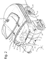
- the vehicle 1 comprises an electrical drive system 4, a battery system 5 for storing electrical energy and an electronic control system 6 for controlling at least the drive system 4 (shown diagrammatically in Figure 2 ).
- the drive system 4, the battery system 5 and the control system 6 are operatively connected to each other, as is indicated in Figure 2 by dashed lines.
- the drive system 4 comprises two electrical drive motors 43, only one drive motor 43 of which has been shown diagrammatically in Figure 2 .
- the vehicle 1 comprises two rear wheels 44, which are each drivable by means of in each case a drive motor 43.
- the vehicle 1 rests on the floor by means of a manure slide on its front side.
- the vehicle 1 may also rest on the floor in another way, for example by means of a front wheel or a support element, such as a slide block.
- the drive motors 43 of the rear wheels 44 are independently controllable by means of the control system 6.
- the vehicle 1 can be steered, i.e. the control system 6 is able to determine the direction of travel of the vehicle 1 and make the vehicle 1 follow a desired route.
- the electronic control system 6 comprises a control unit, which is shown diagrammatically in Figure 2 .
- the control unit comprises, for example, a printed circuit board and other electronic components.
- the battery system 5 comprises a rechargeable battery (likewise shown diagrammatically in Figure 2 ).
- the drive system 4 and the control system 6 are supplied with electrical energy by means of the battery system 5.
- the rechargeable battery of the battery system 5 and the control unit of the electronic control system 6 are accommodated in the interior space 9 of a housing 8 of the vehicle 1.
- further components may be arranged in the interior space 9.
- as many as possible components which are not able to withstand manure and/or urine, which are often also relatively expensive, such as electronics are accommodated in the interior space 9.
- the housing 8 comprises an access opening 10 in order to render the interior space 9 accessible, for example for maintenance work.
- the access opening 10 is closable by a cover 11, which is connected to the vehicle 1 by means of hinges 12.
- the cover 11 is hingeable about a horizontal hinge axis 14 defined by the hinges 12 between a closed position illustrated in Figure 1 and an open position (see Figure 2 ).
- the access opening 10 is closed by the cover 11, i.e. the cover 11 engages over a peripheral edge 40 of the access opening 10.
- the interior space 9 is then protected from the very dirty external environment of the vehicle 1.
- the open position the interior space 9 of the housing 8 is accessible via the access opening 10.
- the vehicle 1 comprises a retaining device 16 for releasably retaining the cover 11 in the closed position.
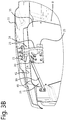
- the retaining device 16 comprises a securing device 17, which is shown most clearly in Figures 3a and 3b .
- the securing device 17 has a securing position, in which the cover 11 is secured in the closed position (see Figure 3a ).
- the securing device 17 comprises an eyelet 21, which is attached to the cover 11, and a securing part 20, which is connected to a manually operable element on the outside of the vehicle 1, in this exemplary embodiment a handle 18, via a transmission mechanism 19.
- the eyelet 21 engages with the securing part 20 in such a way that the securing position is reached automatically.
- the securing device 17 is operable from the securing position to a release position illustrated in Figure 3b , in which the eyelet 21 is released by the securing part 20 and the cover 11 is movable from the closed position upwards.
- the vehicle 11 comprises a locking device 23. If the cover 11 is released by the securing device 17 and is moved from the closed position in the direction of the open position, the locking device 23 locks the cover 11 in a partly open position near the closed position, i.e. the cover 11 is locked while leaving a gap-like opening between the peripheral edge 40 of the access opening 10 and an outer edge 41 of the cover 11.
- the height A of the gap-like opening is for example approximately 10 cm.
- the locking device 23 comprises a hook part 24 and an engagement part 25.
- the engagement part 25 is attached to a plate part 35 which forms the front of the housing 8.
- the hook part 24 is connected to the cover 11 and is situated next to the eyelet 21 of the securing device 17.
- the hook part 24 is hingeable about a hinge axis 26 between an engagement position and a release position.
- the hook part 24 is prestressed into the engagement position (see Figures 3a , 3b , 4a ) by means of a spring means, in this exemplary embodiment a torsion spring 27 which is prestressed between a recess 28 in the hook part 24 and a stop which is attached to the cover 11 and has an opening 30 in which a curved end 29 of the torsion spring 27 is accommodated.
- a spring means in this exemplary embodiment a torsion spring 27 which is prestressed between a recess 28 in the hook part 24 and a stop which is attached to the cover 11 and has an opening 30 in which a curved end 29 of the torsion spring 27 is accommodated.
- the hook part 24 is situated at a distance from the engagement part 25.
- the hook part 24 only engages with the engagement part 25 of the housing 8 when the cover 11 is moved upwards from the closed position to the partly open position (see Figures 3b and 4a ).
- the cover 11 is then locked by the hook part 24 and the engagement part 25 of the locking device 23.
- the hook part 24 and the engagement part 25 are formed in such a way that the cover 11 has to be moved slightly back from the partly open position into the direction of the closed position (see Figure 4b ) in order to bring the hook part 24 into the release position and out of engagement with the engagement part 25 counter to the action of the prestressed torsion spring 27.
- the distance B illustrated in Figure 4b is the height between the peripheral edge 40 of the access opening 10 and the outer edge 41 of the cover 11 after the cover 11 has been lowered slightly.
- the distance B is smaller than the distance A illustrated in Figures 3b and 4a . Only then, while the hook part 24 is held in the release position, i.e. the hook part 24 stays out of engagement with the engagement part 25, can the hook part 24 move along the engagement part 25 and the cover 11 be moved beyond the partly open position towards the completely open position (see Figures 4c and 4d ).
- the securing device 17 is therefore first released by operating the handle 18. Thereafter, the cover 11 is lifted to the partly open position and locked by the locking device 23. This locking device 23 is then unlocked by lowering the cover 11 slightly, and then bringing the hook part 24 to the release position counter to the action of the torsion spring 27 by reaching into the gap-like opening with a hand, i.e. while the cover is partly open. Only then is it possible to move the cover further until it is in the completely open position. As a result thereof, it is hardly possible, if at all, for an animal to open the cover 11 unintentionally.
- the interior space 9 containing the relatively expensive components is very reliably protected from the dirty environment in which the vehicle 1 operates.
- Figure 6 shows a second embodiment according to the invention, which only differs from the first embodiment in that the retaining device 16 comprises a snap-fit device, which may also be referred to as a click-fit device, instead of the securing device 17.
- the snap-fit device comprises a spherical snap-fit element 46 which is attached to the cover 11.
- the snap-fit element 46 is snap-fitted or click-fitted in an receiving element 47.
- the cover 11 is releasable from the snap-fit device 46, 47 by exerting a force on the cover 11 in the direction of the open position which is greater than a threshold value determined by the snap-fit device 46, 47.
- the snap-fit device 46,47 reliably retains the cover 11 in the closed position, so that the cover 11 does not, for example, bounce up and down if the vehicle 1 moves across uneven structures on the floor. At the same time, the snap-fit device 46, 47 can readily be pulled loose. The cover 11 may then be lifted to the partly open position, in which the locking device 23 locks the cover 11 as described above.
- the locking device 23 according to the invention is not only suitable for new vehicles, but may also be retrofitted to existing vehicles which are already in use on a farm.
- the plate part 35 of the housing 8 is detachable by removing bolts.
- the plate part 35 of an existing vehicle can easily be replaced by a replacement plate part 35 with an engagement part 25 which is attached thereto, for example welded on (see Figure 5 ).
- the hook part 24 By fitting the hook part 24 to the cover 11 of the existing vehicle, the locking device 23 is added.
- the conversion of an existing vehicle is readily possible by providing a converting kit comprising a replacement plate part 35 with engagement part 25 and the hook part 24 with associated components.
- an autonomous vehicle for cleaning a floor of an animal shed is described above, the invention may also be used with other autonomous vehicles for performing an animal-related operation, such as an autonomous vehicle for pushing feed to a feeding fence, or an autonomous vehicle for automatically feeding animals, such as cows.
- Such vehicles are not situated in between the animals, but are nevertheless sufficiently close to the animals that identical or similar risks of exposure to manure and urine of the animals play a part.
Landscapes
- Life Sciences & Earth Sciences (AREA)
- Environmental Sciences (AREA)
- Animal Husbandry (AREA)
- Biodiversity & Conservation Biology (AREA)
- Zoology (AREA)
- Birds (AREA)
- Housing For Livestock And Birds (AREA)
- Lock And Its Accessories (AREA)
Abstract
Description
- The invention relates to an autonomous, and preferably unmanned, vehicle for performing an animal-related operation, in particular cleaning a floor in an animal shed containing animals, such as cows, which vehicle comprises:
- a drive system for driving the vehicle, which drive system is provided with at least one electrical drive motor,
- an electronic control system which is connected to the drive system in order to control it,
- a battery system for storing electrical energy, which battery system is connected to the drive system and the control system,
- a housing having an interior space, in which the control system and/or the battery system are at least partly fitted, which housing is provided with an access opening for making the interior space accessible, for example for maintenance work, and a cover, which is displaceable between a closed position, in which the access opening is closed by the cover, and an open position, in which the interior space of the housing is accessible via the access opening,
- a retaining device for releasably retaining the cover in the closed position.
- The Lely Discovery 120 Collector ® is known. This is an autonomous vehicle for sucking up manure from the floor of an animal shed. The vehicle is supported on the floor by means of two wheels and a manure slide. The vehicle is situated in a very dirty environment between the animals in the animal shed, as a result of which the vehicle becomes heavily soiled with manure and urine from the animals in use. The vehicle is able to find its way autonomously by means of an electronic control system using sensors, such as an ultrasound sensor and a gyroscope. On the basis of the signals detected by the sensors, the control system controls a drive system with electrical drive motors for the wheels of the vehicle. Due to the fact that the two rear wheels are operable independently from each other, it is possible for the vehicle to be steered and follow a desired route. The drive system and the control system are supplied by a battery system on board of the vehicle.
- The electronic control system and the battery system comprise relatively expensive and delicate components, such as the sensors, which are arranged in an interior space of a housing of the vehicle. The interior space comprises an access opening which is closed by a cover during use. The cover is hingeable about a substantially horizontal hinge axis between a closed position and an open position. In the open position, the interior space is accessible, for example for maintenance work. The cover is automatically secured mechanically upon closure and retained in the closed position in order to protect the interior space against the very dirty environment of the animal shed during use. The automatic securing means can easily be released by operating a handle.
- However, it has been found in practice, that the cover does not always remain closed. If the cover is not properly closed, the automatic securing means is not activated, i.e. the securing means does not properly retain the cover in the closed position. In addition, there is a risk that the automatic securing means inadvertently opens during use, for example as a result of vibrations. In addition, it is possible that the animals inadvertently operate the handle for releasing the cover, after which the animals can easily move the cover to the open position. As a result thereof, the interior space containing the components of the electronic control system and the battery system is exposed to the very dirty environment of the animal shed. The manure and urine of the animals in the animal shed can damage the electronic control system and the battery system. It is also possible that the animals will stand in the interior space, which will likewise cause expensive damage.
- It is an object of the invention to provide an improved autonomous vehicle for performing an animal-related operation, in particular an autonomous vehicle for cleaning a floor in an animal shed containing animals, such as cows, wherein maintenance work to the electronic control system and the battery system are readily possible and the risk of damage due to the very dirty environment, such as by manure or urine, is reduced at the same time.
- This object is achieved, according to the invention, by the fact that the vehicle comprises a locking device which locks the cover in a partly open position close to the closed position if the cover is released by the retaining device and is moved from the closed position in the direction of the open position, and this locking device is operable so as to reach an unlocked position, while the cover is partly open, in particular with the cover in or close to this partly open position, in order to make it possible for the cover to be movable from the partly open position to the open position. The vehicle according to the invention comprises a retaining device for releasably retaining the cover in the closed position, which is designed, for example, like the automatic mechanical securing means of the known Lely Discovery 120 Collector ®, as well as a locking device for the cover which can only be unlocked after the retaining device has released the cover and the cover has moved slightly from the closed position in the direction of the open position.
- By means of the retaining device and the locking device, the cover according to the invention is only movable to the completely open position in two steps, wherein the second step of unlocking the locking device only becomes possible once the first step of releasing the retaining device has been carried out. As a result thereof, it is virtually impossible for the cover to open inadvertently. At the same time, a person, such as a farmer or maintenance engineer, is still readily able to open the cover by hand and without the use of tools in order to carry out maintenance work on the components of the electronic control system and the battery system. In addition, the partly open position, in which the cover is retained by the locking device, i.e. after the cover has been released by the retaining device and has subsequently been moved slightly in the direction of the open position, is close to the closed position. In particular, in the partly open position, the cover is at a distance from the closed position which is less than 20 cm, preferably less than 10 cm. With such a small opening, it is impossible for manure or urine to end up in the interior space. As a result thereof, the risk of damage by the very dirty environment is significantly reduced. Also, it is not possible for animals to stand in the interior space.
- The retaining device according to the invention may be embodied in various ways.
- For example, the retaining device comprises a securing device which has a securing position, in which the cover is secured in the closed position, and wherein the securing device is operable from this securing position to a a release position, in which the cover is movable from the closed position in the direction of the open position. The securing device according to this embodiment forms a first locking device, whereas the locking device for locking the cover in the partly open position forms a second locking device. While the vehicle is moving, the cover is secured in the closed position by the securing device, i.e. the first locking device. The securing device is operable, for example by manually unlocking it, from the securing position to the release position, in which the cover can move to the partly open position. Once this is reached, the cover is locked by the locking device according to the invention, i.e. the second locking device, which will subsequently also have to be unlocked in order to move the cover further into the completely open position and gain access to the interior space.
- According to the invention, when the securing device is in the release position, it is possible for the securing device to be moved to the securing position automatically when closing the cover. In this case, the securing device automatically ends up in the securing position when closing the cover, for example as is the case with the automatic mechanical securing means of the known Lely Discovery 120 Collector ®. In addition, the securing device may comprise a manually operable element which is arranged on the outside of the vehicle, wherein the securing device is operable from the securing position to the release position by operating the manually operable element. The manually operable element comprises, for example, a handle or button. This is simple and reliable.
- In an alternative embodiment according to the invention, the retaining device comprises a snap-fit device, wherein the cover is snap-fitted into the closed position upon closure thereof, and wherein the cover is releasable from the snap-fit device by applying a force on the cover which is directed towards the open position and which is greater than a threshold value determined by the snap-fit device. The snap-fit device, which may also be referred to as a click-fit device, comprises, for example, one or more snap-fit means which are arranged on the cover and the housing. In this embodiment, the cover is click-fitted upon closure by means of the snap-fit device and thus retained in the closed position. The costs of such a snap-fit device are relatively low. At the same time, the cover remains reliably in the closed position, even if the vehicle is subjected to vibrations during moving. In order to open the cover, a person pulls on the cover using sufficient force, so that the cover snaps out of the snap-fit connection (first step). In this case, the cover is retained by the locking device according to the invention, which then has to be unlocked (second step) in order to be able to open the cover completely.
- In an embodiment according to the invention, the cover is hingeable between the closed position and the open position about a substantially horizontal axis, wherein the cover, upon moving it from the closed position in the direction of the open position, is displaced upwards, counter to the action of the force of gravity. If the cover is released at a suitable height above the closed position, the cover will, on account of its own weight, become fixed on the retaining device, such as the above-described securing device or snap-fit device. In that case, the cover does not have to be pushed down until it reaches the closed position. This is user-friendly and reliable.
- The locking device according to the invention, i.e. the locking device for locking the cover in the partly open position, may be designed in various ways.
- It is preferable for the locking device to be provided with a hook part and an engagement part, wherein one of these parts is arranged on the cover and the other part on the housing, and wherein the hook part is movable, preferably hingeable, between an engagement position, in which, upon moving the cover from the closed position to the partly open position, the hook part engages with the engagement part for locking the cover, and a release position, in which the hook part is out of engagement with the engagement part and the cover is movable beyond the partly open position in the direction of the open position. As a result thereof, the risk of an animal, such as a cow, inadvertently opening the cover is minimal. In order to move the cover to the open position, the hook part has to be moved to the release position in the partly open position of the cover, i.e. via a small intermediate space between the cover and the edge of the access opening. The release position of the hook part determines the unlocked position of the locking device according to the invention. It is virtually impossible for an animal, such as a cow, to unintentionally unlock the locking device according to the invention. This also significantly reduces the risk of damage to the electronic components in the interior space, such as by manure or urine from the animals or due to the fact that the animals step into the interior space.
- The hook part may be arranged in such a way that the hook part tends to move towards the engagement position on account of the force of gravity. However, it is preferable if the hook part is prestressed into the engagement position by means of a spring means. The spring means comprises, for example, a torsion spring. By using the spring means, it is ensured that the hook part engages with the engagement part when it is moved from the closed position to the partly open position. This is useful for the reliability of the lock according to the invention.
- In an embodiment according to the invention, the hook part is situated at a distance from the engagement part in the closed position of the cover, wherein the hook part only comes into engagement with the engagement part when moving the cover from the closed position to the partly open position. In the closed position, the cover is retained by the retaining device, such as the above-described securing device or snap-fit device. The hook part of the lock according to the invention is then inactive. The hook part only engages with the engagement part, i.e. the locking device according to the invention only locks the cover, after the cover has been released by the retaining device and the cover has been moved from the closed position into the partly open position. As a result thereof, the cover can only be opened completely by performing two specific operations in succession. The risk of the cover being opened unintentionally is thus minimal.
- In a preferred embodiment according to the invention, the hook part and/or the engagement part are formed in such a way that, after the hook part has engaged with the engagement part in the engagement position by moving the cover from the closed position to the partly open position, the cover has to be moved slightly back from the partly open position in the direction of the closed position in order to bring the hook part into the release position and out of engagement with the engagement part, and wherein the cover is only then, while the hook part is held in the release position, movable beyond the partly open position in the direction of the open position,. By requiring such a specific manipulation of the hook part and the cover in order to open the cover, it is ensured that the cover can only be opened intentionally by a person. The electronic components in the interior space are safely protected while the vehicle moves between the animals in the animal shed.
- In an embodiment according to the invention, the housing comprises a detachable plate part, wherein one of the hook part and the engagement part is arranged on that plate part of the housing, and wherein the other of those parts is arranged on the cover. The housing of the known Lely Discovery 120 Collector ® has a detachable plate part. By replacing the plate part of the housing with a replacement plate part comprising the engagement part, and fitting the hook part to the cover, or vice versa, an existing Lely Discovery 120 Collector ® which is already in use on a farm can be retrofitted with the locking device according to the invention. As a result thereof, the above-described advantages are achieved. The costs of such a modification are low.
- According to the invention, the locking device can lock the cover in a partly open position near the closed position. In particular, the housing comprises a peripheral edge which defines the access opening, wherein the cover comprises an outer edge which, in the partly open position, is situated at a distance from the peripheral edge of the access opening which is less than 20 cm, preferably less than 10 cm, such as less than 5 cm. In the partly open position, such a distance defines a gap-like intermediate space between the edge of the access opening and the cover. An animal is not able to unintentionally operate the locking device according to the invention via this intermediate space.
- In a preferred embodiment according to the invention, the vehicle comprises a cleaning device for cleaning a floor in an animal shed containing animals, in particular cows. The cleaning device comprises, for example, a manure-sucking device for sucking up manure from the floor of the animal shed, and/or a manure slide for moving manure across the floor of the animal shed, in particular through slots in a slatted floor of the animal shed. The vehicle according to the invention is designed to drive between animals in an animal shed. Since the vehicle is then in a very dirty environment, it is particularly important for delicate and expensive components in the interior space of the housing of the vehicle to be protected.
- The invention also relates to a method for modifying an autonomous vehicle as described above, in particular on a farm, wherein a locking device according to the invention as described above is arranged on the vehicle. In particular, the housing of the vehicle comprises a detachable plate part, wherein one of the hook part and the engagement part is arranged on said plate part of the housing, and wherein the other of those parts is arranged on the cover, and wherein the detachable plate part of the housing of the vehicle is replaced by a replacement plate part with one of the hook part and the engagement part, and wherein the other of those parts is arranged on the cover. The replacement of the plate part in its entirety is simpler than retrofitting the engagement part or the hook part to the existing plate part. Therefore, an existing autonomous vehicle which is already in use on a farm can readily be converted, so that the above-described advantages are achieved, in particular the improved protection of the electronic components.
- The invention furthermore relates to a converting kit for modifying an autonomous vehicle with a housing which comprises a detachable plate part, as described above, wherein the converting kit is provided with or consists of a replacement plate part for replacing the detachable plate part, an engagement part and a hook part. The engagement part is attached to the replacement plate part, for example by welding or otherwise. The hook part is configured to be fitted to the cover of the vehicle. Alternatively, the hook part may be attached to the replacement plate part, whereas the engagement part is fitted to the cover. The use of the converting kit makes converting an existing vehicle quick and simple.
- The invention will now be explained in more detail with reference to the figures, in which:
-
Figure 1 shows a perspective view of a first embodiment of an autonomous vehicle according to the invention, wherein the cover is closed. -
Figure 2 shows a perspective view of the vehicle illustrated inFigure 1 , wherein the cover is open. -
Figures 3a and3b show perspective views of the retaining device and the locking device of the vehicle illustrated inFigure 1 , wherein the cover is closed or partly open, respectively. -
Figures 4a-4d show side views of various steps during the unlocking of the locking device of the vehicle illustrated inFigure 1 . -
Figure 5 shows a converting kit according to the invention. -
Figure 6 shows a perspective view of a second embodiment of an autonomous vehicle according to the invention, wherein the cover is open. - An autonomous vehicle for cleaning a floor in an animal shed containing animals, such as cows, is denoted in the figures by
reference numeral 1. Thevehicle 1 is driverless and self-propelled. Thevehicle 1 is situated between the animals, i.e. in a very dirty environment containing manure and urine. - In this exemplary embodiment, the
vehicle 1 comprises acleaning device 7, which is designed to suck up manure and/or urine from thefloor 2. Such acleaning system 7 is described in detail inWO 2013/010785 A1 , the contents of which are deemed to be incorporated in the present patent application by reference, and will not be explained in more detail now. It should be noted that the cleaning system may also be designed differently. For example, the cleaning system of thevehicle 1 comprises a manure slide for moving manure and/or urine across a slatted floor with slots. Such a cleaning system is described in detail inWO 00/70937 A1 - The
vehicle 1 comprises anelectrical drive system 4, abattery system 5 for storing electrical energy and anelectronic control system 6 for controlling at least the drive system 4 (shown diagrammatically inFigure 2 ). Thedrive system 4, thebattery system 5 and thecontrol system 6 are operatively connected to each other, as is indicated inFigure 2 by dashed lines. - The
drive system 4 comprises twoelectrical drive motors 43, only onedrive motor 43 of which has been shown diagrammatically inFigure 2 . Thevehicle 1 comprises tworear wheels 44, which are each drivable by means of in each case adrive motor 43. In this exemplary embodiment, thevehicle 1 rests on the floor by means of a manure slide on its front side. However, thevehicle 1 may also rest on the floor in another way, for example by means of a front wheel or a support element, such as a slide block. Thedrive motors 43 of therear wheels 44 are independently controllable by means of thecontrol system 6. Thus, thevehicle 1 can be steered, i.e. thecontrol system 6 is able to determine the direction of travel of thevehicle 1 and make thevehicle 1 follow a desired route. - The
electronic control system 6 comprises a control unit, which is shown diagrammatically inFigure 2 . The control unit comprises, for example, a printed circuit board and other electronic components. Thebattery system 5 comprises a rechargeable battery (likewise shown diagrammatically inFigure 2 ). Thedrive system 4 and thecontrol system 6 are supplied with electrical energy by means of thebattery system 5. The rechargeable battery of thebattery system 5 and the control unit of theelectronic control system 6 are accommodated in theinterior space 9 of ahousing 8 of thevehicle 1. Obviously, further components may be arranged in theinterior space 9. Preferably, as many as possible components which are not able to withstand manure and/or urine, which are often also relatively expensive, such as electronics, are accommodated in theinterior space 9. - The
housing 8 comprises an access opening 10 in order to render theinterior space 9 accessible, for example for maintenance work. Theaccess opening 10 is closable by acover 11, which is connected to thevehicle 1 by means of hinges 12. Thecover 11 is hingeable about ahorizontal hinge axis 14 defined by thehinges 12 between a closed position illustrated inFigure 1 and an open position (seeFigure 2 ). In the closed position, the access opening 10 is closed by thecover 11, i.e. thecover 11 engages over aperipheral edge 40 of theaccess opening 10. Theinterior space 9 is then protected from the very dirty external environment of thevehicle 1. In the open position, theinterior space 9 of thehousing 8 is accessible via theaccess opening 10. - In use, it is important that the
cover 11 remains in the closed position, so that manure and/or urine cannot damage the components accommodated in theinterior space 9 and no animals can stand in theinterior space 9 either. Thevehicle 1 comprises a retainingdevice 16 for releasably retaining thecover 11 in the closed position. In the embodiment illustrated inFigure 1 , the retainingdevice 16 comprises a securingdevice 17, which is shown most clearly inFigures 3a and3b . - The securing
device 17 has a securing position, in which thecover 11 is secured in the closed position (seeFigure 3a ). The securingdevice 17 comprises aneyelet 21, which is attached to thecover 11, and a securingpart 20, which is connected to a manually operable element on the outside of thevehicle 1, in this exemplary embodiment ahandle 18, via atransmission mechanism 19. By allowing thecover 11 to drop down under the effect of the force of gravity, theeyelet 21 engages with the securingpart 20 in such a way that the securing position is reached automatically. Via thehandle 18, the securingdevice 17 is operable from the securing position to a release position illustrated inFigure 3b , in which theeyelet 21 is released by the securingpart 20 and thecover 11 is movable from the closed position upwards. - In order to ensure that the
cover 11 can only be opened completely by a person on purpose, thevehicle 11 according to the invention comprises alocking device 23. If thecover 11 is released by the securingdevice 17 and is moved from the closed position in the direction of the open position, the lockingdevice 23 locks thecover 11 in a partly open position near the closed position, i.e. thecover 11 is locked while leaving a gap-like opening between theperipheral edge 40 of the access opening 10 and anouter edge 41 of thecover 11. The height A of the gap-like opening (seeFigures 3b and4a ) is for example approximately 10 cm. - In this exemplary embodiment, the locking
device 23 comprises ahook part 24 and anengagement part 25. Theengagement part 25 is attached to aplate part 35 which forms the front of thehousing 8. Thehook part 24 is connected to thecover 11 and is situated next to theeyelet 21 of the securingdevice 17. Thehook part 24 is hingeable about ahinge axis 26 between an engagement position and a release position. Thehook part 24 is prestressed into the engagement position (seeFigures 3a ,3b ,4a ) by means of a spring means, in this exemplary embodiment atorsion spring 27 which is prestressed between arecess 28 in thehook part 24 and a stop which is attached to thecover 11 and has anopening 30 in which acurved end 29 of thetorsion spring 27 is accommodated. - As is illustrated in
Figure 3a , in the closed position of thecover 11, thehook part 24 is situated at a distance from theengagement part 25. Thehook part 24 only engages with theengagement part 25 of thehousing 8 when thecover 11 is moved upwards from the closed position to the partly open position (seeFigures 3b and4a ). Thecover 11 is then locked by thehook part 24 and theengagement part 25 of thelocking device 23. - The
hook part 24 and theengagement part 25 are formed in such a way that thecover 11 has to be moved slightly back from the partly open position into the direction of the closed position (seeFigure 4b ) in order to bring thehook part 24 into the release position and out of engagement with theengagement part 25 counter to the action of theprestressed torsion spring 27. The distance B illustrated inFigure 4b is the height between theperipheral edge 40 of the access opening 10 and theouter edge 41 of thecover 11 after thecover 11 has been lowered slightly. The distance B is smaller than the distance A illustrated inFigures 3b and4a . Only then, while thehook part 24 is held in the release position, i.e. thehook part 24 stays out of engagement with theengagement part 25, can thehook part 24 move along theengagement part 25 and thecover 11 be moved beyond the partly open position towards the completely open position (seeFigures 4c and 4d ). - In order to unlock the
cover 11 according to the invention, the securingdevice 17 is therefore first released by operating thehandle 18. Thereafter, thecover 11 is lifted to the partly open position and locked by the lockingdevice 23. Thislocking device 23 is then unlocked by lowering thecover 11 slightly, and then bringing thehook part 24 to the release position counter to the action of thetorsion spring 27 by reaching into the gap-like opening with a hand, i.e. while the cover is partly open. Only then is it possible to move the cover further until it is in the completely open position. As a result thereof, it is hardly possible, if at all, for an animal to open thecover 11 unintentionally. Theinterior space 9 containing the relatively expensive components is very reliably protected from the dirty environment in which thevehicle 1 operates. -
Figure 6 shows a second embodiment according to the invention, which only differs from the first embodiment in that the retainingdevice 16 comprises a snap-fit device, which may also be referred to as a click-fit device, instead of the securingdevice 17. In this exemplary embodiment, the snap-fit device comprises a spherical snap-fit element 46 which is attached to thecover 11. When closing thecover 11, the snap-fit element 46 is snap-fitted or click-fitted in an receivingelement 47. Thecover 11 is releasable from the snap-fit device cover 11 in the direction of the open position which is greater than a threshold value determined by the snap-fit device fit device cover 11 in the closed position, so that thecover 11 does not, for example, bounce up and down if thevehicle 1 moves across uneven structures on the floor. At the same time, the snap-fit device cover 11 may then be lifted to the partly open position, in which thelocking device 23 locks thecover 11 as described above. - The locking
device 23 according to the invention is not only suitable for new vehicles, but may also be retrofitted to existing vehicles which are already in use on a farm. Theplate part 35 of thehousing 8 is detachable by removing bolts. Theplate part 35 of an existing vehicle can easily be replaced by areplacement plate part 35 with anengagement part 25 which is attached thereto, for example welded on (seeFigure 5 ). By fitting thehook part 24 to thecover 11 of the existing vehicle, the lockingdevice 23 is added. The conversion of an existing vehicle is readily possible by providing a converting kit comprising areplacement plate part 35 withengagement part 25 and thehook part 24 with associated components. - Although an autonomous vehicle for cleaning a floor of an animal shed is described above, the invention may also be used with other autonomous vehicles for performing an animal-related operation, such as an autonomous vehicle for pushing feed to a feeding fence, or an autonomous vehicle for automatically feeding animals, such as cows. Such vehicles are not situated in between the animals, but are nevertheless sufficiently close to the animals that identical or similar risks of exposure to manure and urine of the animals play a part.
Claims (16)
- Autonomous vehicle for performing an animal-related operation, in particular cleaning a floor in an animal shed containing animals, such as cows, which vehicle (1) comprises:- a drive system (4) for driving the vehicle (1), which drive system (4) is provided with at least one electrical drive motor (43),- an electronic control system (6) which is connected to the drive system (4) in order to control it,- a battery system (5) for storing electrical energy, which battery system (5) is connected to the drive system (4) and the control system (6),- a housing (8) having an interior space (9), in which the control system (6) and/or the battery system (5) are at least partly arranged, which housing (8) is provided with an access opening (10) for making the interior space (9) accessible, and a cover (11), which is displaceable between a closed position, in which the access opening (10) is closed by the cover (11), and an open position, in which the interior space (9) of the housing (8) is accessible via the access opening (10),- a retaining device (16) for releasably retaining the cover (11) in the closed position,characterized in that the vehicle (1) comprises a locking device (23), which locks the cover (11) in a partly open position close to the closed position if the cover (11) is released by the retaining device (16) and is moved from the closed position in the direction of the open position, and said locking device (23) is operable so as to reach an unlocked position, while the cover is partly open, in order to make it possible for the cover (11) to be movable from the partly open position to the open position.
- Vehicle according to Claim 1, wherein the retaining device (16) comprises a securing device (17) which has a securing position, in which the cover (11) is secured in the closed position, and wherein the securing device (17) is operable from said securing position to a release position, in which the cover (11) is movable from the closed position in the direction of the open position.
- Vehicle according to Claim 2, wherein, when the securing device (17) is in the release position, the securing device (17) is automatically moved to the securing position when closing the cover (11), and wherein the securing device (17) comprises a manually operable element (18), which is arranged on the outside of the vehicle (1), and wherein the securing device (17) is operable from the securing position to the release position by operating the manually operable element (18).
- Vehicle according to Claim 1, wherein the retaining device comprises a snap-fit device (46, 47), wherein the cover (11) is snap-fitted into the closed position upon closure thereof, and wherein the cover (11) is releasable from the snap-fit device (46, 47) by applying a force on the cover (11) which is directed towards the open position and which is greater than a threshold value determined by the snap-fit device (46, 47).
- Vehicle according to one of the preceding claims, wherein the cover (11) is hingeable between the closed position and the open position about a substantially horizontal axis (14), and wherein the cover (11), upon moving it from the closed position in the direction of the open position upwards, is displaced counter to the action of the force of gravity.
- Vehicle according to one of the preceding claims, wherein the locking device (23) is provided with a hook part (24) and an engagement part (25), wherein one of these parts (24, 25) is arranged on the cover (11) and the other part (24, 25) on the housing (8), and wherein the hook part (24) is movable between an engagement position, in which, upon moving the cover (11) from the closed position to the partly open position, the hook part (24) engages with the engagement part (25) for locking the cover (11), and a release position, in which the hook part (24) is out of engagement with the engagement part (25) and the cover (11) is movable beyond the partly open position in the direction of the open position.
- Vehicle according to Claim 6, wherein the hook part (24) is prestressed into the engagement position by means of a spring means (27).
- Vehicle according to Claim 6 or 7, wherein the hook part (24) is situated at a distance from the engagement part (25) in the closed position of the cover (11), and wherein the hook part (24) only comes into engagement with the engagement part (25) when moving the cover (11) from the closed position to the partly open position.
- Vehicle according to one of Claims 6-8, wherein the hook part (24) and/or the engagement part (25) are formed in such a way that, after the hook part (24) has engaged with the engagement part (25) in the engagement position by moving the cover (11) from the closed position to the partly open position, the cover (11) has to be moved slightly back from the partly open position in the direction of the closed position in order to bring the hook part (24) into the release position and out of engagement with the engagement part, and wherein the cover (11) is only then movable beyond the partly open position in the direction of the open position, while the hook part (24) is held in the release position.
- Vehicle according to one of Claims 6-9, wherein the housing (8) comprises a detachable plate part (35), and wherein one of the hook part (24) and the engagement part (25) is arranged on said plate part (35) of the housing (8), and wherein the other of those parts (24, 25) is arranged on the cover (11).
- Vehicle according to one of the preceding claims, wherein the housing (8) comprises a peripheral edge (40) which defines the access opening (10), and wherein the cover (11) comprises an outer edge (41) which, in the partly open position, is situated at a distance from the peripheral edge (40) of the access opening (10) which is less than 20 cm, preferably less than 10 cm, such as less than 5 cm.
- Vehicle according to one of the preceding claims, wherein the vehicle (1) is provided with a cleaning device (7) for cleaning a floor (2) in an animal shed containing animals, in particular cows.
- Method for modifying an autonomous vehicle (1) according to the preamble of Claim 1, in particular on a farm, wherein a locking device (23) according to the characterising portion of Claim 1 is arranged on the vehicle (1).
- Method according to Claim 13, wherein the vehicle (1) is configured according to Claim 10, and wherein the detachable plate part (35) of the housing (8) of the vehicle (1) is replaced by a replacement plate part (35) with one of the hook part (24) and the engagement part (25), wherein the other one of those parts (24, 25) is arranged on the cover (11).
- Converting kit for carrying out the method according to Claim 13 or 14.
- Converting kit according to Claim 15 in so far as dependent on Claim 14, wherein the converting kit is provided with a replacement plate part (35) for replacing the detachable plate part, an engagement part (25) and a hook part (24), wherein the engagement part (25) or the hook part (24) is attachable to the replacement plate part (35), and the other of these parts (24, 25) is configured to be fitted to the cover (11) of the vehicle (1).
Applications Claiming Priority (1)
| Application Number | Priority Date | Filing Date | Title |
|---|---|---|---|
| NL2021535A NL2021535B1 (en) | 2018-08-31 | 2018-08-31 | Autonomous vehicle, method for adapting such a vehicle, as well as conversion kit |
Publications (3)
| Publication Number | Publication Date |
|---|---|
| EP3616506A1 true EP3616506A1 (en) | 2020-03-04 |
| EP3616506B1 EP3616506B1 (en) | 2024-03-06 |
| EP3616506C0 EP3616506C0 (en) | 2024-03-06 |
Family
ID=63638264
Family Applications (1)
| Application Number | Title | Priority Date | Filing Date |
|---|---|---|---|
| EP19190115.6A Active EP3616506B1 (en) | 2018-08-31 | 2019-08-05 | Autonomous vehicle, method for modifying such a vehicle, and converting kit |
Country Status (3)
| Country | Link |
|---|---|
| EP (1) | EP3616506B1 (en) |
| CA (1) | CA3053190A1 (en) |
| NL (1) | NL2021535B1 (en) |
Cited By (1)
| Publication number | Priority date | Publication date | Assignee | Title |
|---|---|---|---|---|
| CN111296301A (en) * | 2020-03-07 | 2020-06-19 | 夏建秋 | Pet excrement clearing device |
Families Citing this family (1)
| Publication number | Priority date | Publication date | Assignee | Title |
|---|---|---|---|---|
| NL2027114B1 (en) * | 2020-12-15 | 2022-07-08 | Lely Patent Nv | System and method for removing manure from a floor in a stable, as well as manure removal vehicle |
Citations (3)
| Publication number | Priority date | Publication date | Assignee | Title |
|---|---|---|---|---|
| WO2000070937A1 (en) | 1999-05-25 | 2000-11-30 | Lely Research Holding Ag | An unmanned vehicle for displacing manure |
| WO2013010785A1 (en) | 2011-07-15 | 2013-01-24 | Lely Patent N.V. | Manure-removal device |
| US20140319848A1 (en) * | 2013-04-29 | 2014-10-30 | GM Global Technology Operations LLC | Latch assembly release effort control, and method thereof |
-
2018
- 2018-08-31 NL NL2021535A patent/NL2021535B1/en not_active IP Right Cessation
-
2019
- 2019-08-05 EP EP19190115.6A patent/EP3616506B1/en active Active
- 2019-08-27 CA CA3053190A patent/CA3053190A1/en active Pending
Patent Citations (3)
| Publication number | Priority date | Publication date | Assignee | Title |
|---|---|---|---|---|
| WO2000070937A1 (en) | 1999-05-25 | 2000-11-30 | Lely Research Holding Ag | An unmanned vehicle for displacing manure |
| WO2013010785A1 (en) | 2011-07-15 | 2013-01-24 | Lely Patent N.V. | Manure-removal device |
| US20140319848A1 (en) * | 2013-04-29 | 2014-10-30 | GM Global Technology Operations LLC | Latch assembly release effort control, and method thereof |
Non-Patent Citations (1)
| Title |
|---|
| LELY INDUSTRIES: "LELY DISCOVERY 120 COLLECTOR Mobile Barn Cleaner", 15 November 2017 (2017-11-15), XP055583513, Retrieved from the Internet <URL:http://www.lelynet.com/_layouts/15/document/TechDocHandler.aspx?name=5-4008-8501-0_B.pdf&mode=view> [retrieved on 20190425] * |
Cited By (1)
| Publication number | Priority date | Publication date | Assignee | Title |
|---|---|---|---|---|
| CN111296301A (en) * | 2020-03-07 | 2020-06-19 | 夏建秋 | Pet excrement clearing device |
Also Published As
| Publication number | Publication date |
|---|---|
| NL2021535B1 (en) | 2020-04-30 |
| CA3053190A1 (en) | 2020-02-29 |
| EP3616506B1 (en) | 2024-03-06 |
| EP3616506C0 (en) | 2024-03-06 |
Similar Documents
| Publication | Publication Date | Title |
|---|---|---|
| EP3616506B1 (en) | Autonomous vehicle, method for modifying such a vehicle, and converting kit | |
| US10334777B2 (en) | Electric work vehicle | |
| EP3758977B1 (en) | End effector, electrical charging device and method | |
| JP2010035773A (en) | Side brush support device for cleaning robot | |
| US10016115B2 (en) | Lifting device and dishwasher | |
| EP0497498B1 (en) | Improvements relating to trailers | |
| EP2618653B1 (en) | Litter box for domestic animals | |
| DE202017002619U1 (en) | vacuum cleaner | |
| EP3555375A2 (en) | Loader with telescopic lift arm | |
| WO2000049967A1 (en) | Method and system for detecting estrus in swine | |
| WO2015005801A1 (en) | Autonomous device for cleaning a surface of a submerged structure | |
| JP4139251B2 (en) | Electric management machine | |
| CA2337774A1 (en) | An unmanned vehicle for displacing manure | |
| EP3549424B1 (en) | Lawn mower robot | |
| EP1074458B1 (en) | Ballast weight arrangement for motor vehicles | |
| AU2005287951B2 (en) | An arrangement and a method to attach a tool to a loader | |
| ES2399498A2 (en) | Method for handling waste e.g. paper waste, collecting container and for emptying container, involves lowering empty container for handling empty container in working position in automatic manner by computerized system | |
| US5524722A (en) | Skid steer loader seat mechanism | |
| US7273244B2 (en) | Protective device for objects placed inside the rear boot of a motor vehicle | |
| US7585016B2 (en) | Construction machine having top door for improved ingress/egress | |
| WO2022063881A1 (en) | Method and device for cleaning and/or disinfecting treatment | |
| EP1306249A2 (en) | Air conditioning filter | |
| CA1235350A (en) | Combine stone trap closing mechanism | |
| CN111982529B (en) | Trolley, automatic driving system and storage method | |
| JPH0729806Y2 (en) | Mower grass harvester |
Legal Events
| Date | Code | Title | Description |
|---|---|---|---|
| PUAI | Public reference made under article 153(3) epc to a published international application that has entered the european phase |
Free format text: ORIGINAL CODE: 0009012 |
|
| STAA | Information on the status of an ep patent application or granted ep patent |
Free format text: STATUS: THE APPLICATION HAS BEEN PUBLISHED |
|
| AK | Designated contracting states |
Kind code of ref document: A1 Designated state(s): AL AT BE BG CH CY CZ DE DK EE ES FI FR GB GR HR HU IE IS IT LI LT LU LV MC MK MT NL NO PL PT RO RS SE SI SK SM TR |
|
| AX | Request for extension of the european patent |
Extension state: BA ME |
|
| STAA | Information on the status of an ep patent application or granted ep patent |
Free format text: STATUS: REQUEST FOR EXAMINATION WAS MADE |
|
| 17P | Request for examination filed |
Effective date: 20200904 |
|
| RBV | Designated contracting states (corrected) |
Designated state(s): AL AT BE BG CH CY CZ DE DK EE ES FI FR GB GR HR HU IE IS IT LI LT LU LV MC MK MT NL NO PL PT RO RS SE SI SK SM TR |
|
| GRAP | Despatch of communication of intention to grant a patent |
Free format text: ORIGINAL CODE: EPIDOSNIGR1 |
|
| STAA | Information on the status of an ep patent application or granted ep patent |
Free format text: STATUS: GRANT OF PATENT IS INTENDED |
|
| INTG | Intention to grant announced |
Effective date: 20231012 |
|
| GRAS | Grant fee paid |
Free format text: ORIGINAL CODE: EPIDOSNIGR3 |
|
| GRAA | (expected) grant |
Free format text: ORIGINAL CODE: 0009210 |
|
| STAA | Information on the status of an ep patent application or granted ep patent |
Free format text: STATUS: THE PATENT HAS BEEN GRANTED |
|
| AK | Designated contracting states |
Kind code of ref document: B1 Designated state(s): AL AT BE BG CH CY CZ DE DK EE ES FI FR GB GR HR HU IE IS IT LI LT LU LV MC MK MT NL NO PL PT RO RS SE SI SK SM TR |
|
| REG | Reference to a national code |
Ref country code: CH Ref legal event code: EP |
|
| REG | Reference to a national code |
Ref country code: IE Ref legal event code: FG4D |
|
| REG | Reference to a national code |
Ref country code: DE Ref legal event code: R096 Ref document number: 602019047648 Country of ref document: DE |
|
| U01 | Request for unitary effect filed |
Effective date: 20240311 |
|
| U07 | Unitary effect registered |
Designated state(s): AT BE BG DE DK EE FI FR IT LT LU LV MT NL PT SE SI Effective date: 20240320 |
|
| PG25 | Lapsed in a contracting state [announced via postgrant information from national office to epo] |
Ref country code: GR Free format text: LAPSE BECAUSE OF FAILURE TO SUBMIT A TRANSLATION OF THE DESCRIPTION OR TO PAY THE FEE WITHIN THE PRESCRIBED TIME-LIMIT Effective date: 20240607 |
|
| PG25 | Lapsed in a contracting state [announced via postgrant information from national office to epo] |
Ref country code: RS Free format text: LAPSE BECAUSE OF FAILURE TO SUBMIT A TRANSLATION OF THE DESCRIPTION OR TO PAY THE FEE WITHIN THE PRESCRIBED TIME-LIMIT Effective date: 20240606 Ref country code: HR Free format text: LAPSE BECAUSE OF FAILURE TO SUBMIT A TRANSLATION OF THE DESCRIPTION OR TO PAY THE FEE WITHIN THE PRESCRIBED TIME-LIMIT Effective date: 20240306 |
|
| PG25 | Lapsed in a contracting state [announced via postgrant information from national office to epo] |
Ref country code: ES Free format text: LAPSE BECAUSE OF FAILURE TO SUBMIT A TRANSLATION OF THE DESCRIPTION OR TO PAY THE FEE WITHIN THE PRESCRIBED TIME-LIMIT Effective date: 20240306 |
|
| PG25 | Lapsed in a contracting state [announced via postgrant information from national office to epo] |
Ref country code: RS Free format text: LAPSE BECAUSE OF FAILURE TO SUBMIT A TRANSLATION OF THE DESCRIPTION OR TO PAY THE FEE WITHIN THE PRESCRIBED TIME-LIMIT Effective date: 20240606 Ref country code: NO Free format text: LAPSE BECAUSE OF FAILURE TO SUBMIT A TRANSLATION OF THE DESCRIPTION OR TO PAY THE FEE WITHIN THE PRESCRIBED TIME-LIMIT Effective date: 20240606 Ref country code: HR Free format text: LAPSE BECAUSE OF FAILURE TO SUBMIT A TRANSLATION OF THE DESCRIPTION OR TO PAY THE FEE WITHIN THE PRESCRIBED TIME-LIMIT Effective date: 20240306 Ref country code: GR Free format text: LAPSE BECAUSE OF FAILURE TO SUBMIT A TRANSLATION OF THE DESCRIPTION OR TO PAY THE FEE WITHIN THE PRESCRIBED TIME-LIMIT Effective date: 20240607 Ref country code: ES Free format text: LAPSE BECAUSE OF FAILURE TO SUBMIT A TRANSLATION OF THE DESCRIPTION OR TO PAY THE FEE WITHIN THE PRESCRIBED TIME-LIMIT Effective date: 20240306 |
|
| U20 | Renewal fee for the european patent with unitary effect paid |
Year of fee payment: 6 Effective date: 20240827 |
|
| PG25 | Lapsed in a contracting state [announced via postgrant information from national office to epo] |
Ref country code: IS Free format text: LAPSE BECAUSE OF FAILURE TO SUBMIT A TRANSLATION OF THE DESCRIPTION OR TO PAY THE FEE WITHIN THE PRESCRIBED TIME-LIMIT Effective date: 20240706 |
|
| PG25 | Lapsed in a contracting state [announced via postgrant information from national office to epo] |
Ref country code: SM Free format text: LAPSE BECAUSE OF FAILURE TO SUBMIT A TRANSLATION OF THE DESCRIPTION OR TO PAY THE FEE WITHIN THE PRESCRIBED TIME-LIMIT Effective date: 20240306 |
|
| PG25 | Lapsed in a contracting state [announced via postgrant information from national office to epo] |
Ref country code: CZ Free format text: LAPSE BECAUSE OF FAILURE TO SUBMIT A TRANSLATION OF THE DESCRIPTION OR TO PAY THE FEE WITHIN THE PRESCRIBED TIME-LIMIT Effective date: 20240306 |
|
| PG25 | Lapsed in a contracting state [announced via postgrant information from national office to epo] |
Ref country code: PL Free format text: LAPSE BECAUSE OF FAILURE TO SUBMIT A TRANSLATION OF THE DESCRIPTION OR TO PAY THE FEE WITHIN THE PRESCRIBED TIME-LIMIT Effective date: 20240306 |
|
| PG25 | Lapsed in a contracting state [announced via postgrant information from national office to epo] |
Ref country code: SK Free format text: LAPSE BECAUSE OF FAILURE TO SUBMIT A TRANSLATION OF THE DESCRIPTION OR TO PAY THE FEE WITHIN THE PRESCRIBED TIME-LIMIT Effective date: 20240306 |
|
| PG25 | Lapsed in a contracting state [announced via postgrant information from national office to epo] |
Ref country code: SM Free format text: LAPSE BECAUSE OF FAILURE TO SUBMIT A TRANSLATION OF THE DESCRIPTION OR TO PAY THE FEE WITHIN THE PRESCRIBED TIME-LIMIT Effective date: 20240306 Ref country code: SK Free format text: LAPSE BECAUSE OF FAILURE TO SUBMIT A TRANSLATION OF THE DESCRIPTION OR TO PAY THE FEE WITHIN THE PRESCRIBED TIME-LIMIT Effective date: 20240306 Ref country code: RO Free format text: LAPSE BECAUSE OF FAILURE TO SUBMIT A TRANSLATION OF THE DESCRIPTION OR TO PAY THE FEE WITHIN THE PRESCRIBED TIME-LIMIT Effective date: 20240306 Ref country code: PL Free format text: LAPSE BECAUSE OF FAILURE TO SUBMIT A TRANSLATION OF THE DESCRIPTION OR TO PAY THE FEE WITHIN THE PRESCRIBED TIME-LIMIT Effective date: 20240306 Ref country code: IS Free format text: LAPSE BECAUSE OF FAILURE TO SUBMIT A TRANSLATION OF THE DESCRIPTION OR TO PAY THE FEE WITHIN THE PRESCRIBED TIME-LIMIT Effective date: 20240706 Ref country code: CZ Free format text: LAPSE BECAUSE OF FAILURE TO SUBMIT A TRANSLATION OF THE DESCRIPTION OR TO PAY THE FEE WITHIN THE PRESCRIBED TIME-LIMIT Effective date: 20240306 |
|
| REG | Reference to a national code |
Ref country code: DE Ref legal event code: R097 Ref document number: 602019047648 Country of ref document: DE |
|
| PLBE | No opposition filed within time limit |
Free format text: ORIGINAL CODE: 0009261 |
|
| STAA | Information on the status of an ep patent application or granted ep patent |
Free format text: STATUS: NO OPPOSITION FILED WITHIN TIME LIMIT |
|
| 26N | No opposition filed |
Effective date: 20241209 |
|
| REG | Reference to a national code |
Ref country code: CH Ref legal event code: PL |
|
| PG25 | Lapsed in a contracting state [announced via postgrant information from national office to epo] |
Ref country code: CH Free format text: LAPSE BECAUSE OF NON-PAYMENT OF DUE FEES Effective date: 20240831 Ref country code: MC Free format text: LAPSE BECAUSE OF FAILURE TO SUBMIT A TRANSLATION OF THE DESCRIPTION OR TO PAY THE FEE WITHIN THE PRESCRIBED TIME-LIMIT Effective date: 20240306 |
|
| PG25 | Lapsed in a contracting state [announced via postgrant information from national office to epo] |
Ref country code: IE Free format text: LAPSE BECAUSE OF NON-PAYMENT OF DUE FEES Effective date: 20240805 |
|
| U20 | Renewal fee for the european patent with unitary effect paid |
Year of fee payment: 7 Effective date: 20250901 |
|
| PGFP | Annual fee paid to national office [announced via postgrant information from national office to epo] |
Ref country code: GB Payment date: 20250827 Year of fee payment: 7 |
|
| PG25 | Lapsed in a contracting state [announced via postgrant information from national office to epo] |
Ref country code: CY Free format text: LAPSE BECAUSE OF FAILURE TO SUBMIT A TRANSLATION OF THE DESCRIPTION OR TO PAY THE FEE WITHIN THE PRESCRIBED TIME-LIMIT; INVALID AB INITIO Effective date: 20190805 |
|
| PG25 | Lapsed in a contracting state [announced via postgrant information from national office to epo] |
Ref country code: HU Free format text: LAPSE BECAUSE OF FAILURE TO SUBMIT A TRANSLATION OF THE DESCRIPTION OR TO PAY THE FEE WITHIN THE PRESCRIBED TIME-LIMIT; INVALID AB INITIO Effective date: 20190805 |