EP3616263B1 - Satellite array architecture - Google Patents
Satellite array architecture Download PDFInfo
- Publication number
- EP3616263B1 EP3616263B1 EP18721225.3A EP18721225A EP3616263B1 EP 3616263 B1 EP3616263 B1 EP 3616263B1 EP 18721225 A EP18721225 A EP 18721225A EP 3616263 B1 EP3616263 B1 EP 3616263B1
- Authority
- EP
- European Patent Office
- Prior art keywords
- satellite
- array
- band
- antenna
- signals
- Prior art date
- Legal status (The legal status is an assumption and is not a legal conclusion. Google has not performed a legal analysis and makes no representation as to the accuracy of the status listed.)
- Active
Links
Images



Classifications
-
- B—PERFORMING OPERATIONS; TRANSPORTING
- B64—AIRCRAFT; AVIATION; COSMONAUTICS
- B64G—COSMONAUTICS; VEHICLES OR EQUIPMENT THEREFOR
- B64G1/00—Cosmonautic vehicles
- B64G1/10—Artificial satellites; Systems of such satellites; Interplanetary vehicles
- B64G1/1007—Communications satellites
-
- B—PERFORMING OPERATIONS; TRANSPORTING
- B64—AIRCRAFT; AVIATION; COSMONAUTICS
- B64G—COSMONAUTICS; VEHICLES OR EQUIPMENT THEREFOR
- B64G1/00—Cosmonautic vehicles
- B64G1/10—Artificial satellites; Systems of such satellites; Interplanetary vehicles
- B64G1/1085—Swarms and constellations
-
- B—PERFORMING OPERATIONS; TRANSPORTING
- B64—AIRCRAFT; AVIATION; COSMONAUTICS
- B64G—COSMONAUTICS; VEHICLES OR EQUIPMENT THEREFOR
- B64G1/00—Cosmonautic vehicles
- B64G1/22—Parts of, or equipment specially adapted for fitting in or to, cosmonautic vehicles
- B64G1/222—Parts of, or equipment specially adapted for fitting in or to, cosmonautic vehicles for deploying structures between a stowed and deployed state
- B64G1/2229—Parts of, or equipment specially adapted for fitting in or to, cosmonautic vehicles for deploying structures between a stowed and deployed state characterised by the deployment actuating mechanism
-
- B—PERFORMING OPERATIONS; TRANSPORTING
- B64—AIRCRAFT; AVIATION; COSMONAUTICS
- B64G—COSMONAUTICS; VEHICLES OR EQUIPMENT THEREFOR
- B64G1/00—Cosmonautic vehicles
- B64G1/22—Parts of, or equipment specially adapted for fitting in or to, cosmonautic vehicles
- B64G1/64—Systems for coupling or separating cosmonautic vehicles or parts thereof, e.g. docking arrangements
- B64G1/641—Interstage or payload connectors
-
- B—PERFORMING OPERATIONS; TRANSPORTING
- B64—AIRCRAFT; AVIATION; COSMONAUTICS
- B64G—COSMONAUTICS; VEHICLES OR EQUIPMENT THEREFOR
- B64G1/00—Cosmonautic vehicles
- B64G1/22—Parts of, or equipment specially adapted for fitting in or to, cosmonautic vehicles
- B64G1/64—Systems for coupling or separating cosmonautic vehicles or parts thereof, e.g. docking arrangements
- B64G1/641—Interstage or payload connectors
- B64G1/643—Interstage or payload connectors for arranging multiple satellites in a single launcher
-
- B—PERFORMING OPERATIONS; TRANSPORTING
- B64—AIRCRAFT; AVIATION; COSMONAUTICS
- B64G—COSMONAUTICS; VEHICLES OR EQUIPMENT THEREFOR
- B64G1/00—Cosmonautic vehicles
- B64G1/22—Parts of, or equipment specially adapted for fitting in or to, cosmonautic vehicles
- B64G1/66—Arrangements or adaptations of apparatus or instruments, not otherwise provided for
-
- H—ELECTRICITY
- H01—ELECTRIC ELEMENTS
- H01Q—ANTENNAS, i.e. RADIO AERIALS
- H01Q1/00—Details of, or arrangements associated with, antennas
- H01Q1/27—Adaptation for use in or on movable bodies
- H01Q1/28—Adaptation for use in or on aircraft, missiles, satellites, or balloons
- H01Q1/288—Satellite antennas
-
- H—ELECTRICITY
- H01—ELECTRIC ELEMENTS
- H01Q—ANTENNAS, i.e. RADIO AERIALS
- H01Q21/00—Antenna arrays or systems
- H01Q21/0006—Particular feeding systems
- H01Q21/0018—Space- fed arrays
-
- H—ELECTRICITY
- H01—ELECTRIC ELEMENTS
- H01Q—ANTENNAS, i.e. RADIO AERIALS
- H01Q3/00—Arrangements for changing or varying the orientation or the shape of the directional pattern of the waves radiated from an antenna or antenna system
- H01Q3/44—Arrangements for changing or varying the orientation or the shape of the directional pattern of the waves radiated from an antenna or antenna system varying the electric or magnetic characteristics of reflecting, refracting, or diffracting devices associated with the radiating element
- H01Q3/46—Active lenses or reflecting arrays
-
- H—ELECTRICITY
- H01—ELECTRIC ELEMENTS
- H01Q—ANTENNAS, i.e. RADIO AERIALS
- H01Q5/00—Arrangements for simultaneous operation of antennas on two or more different wavebands, e.g. dual-band or multi-band arrangements
- H01Q5/40—Imbricated or interleaved structures; Combined or electromagnetically coupled arrangements, e.g. comprising two or more non-connected fed radiating elements
- H01Q5/42—Imbricated or interleaved structures; Combined or electromagnetically coupled arrangements, e.g. comprising two or more non-connected fed radiating elements using two or more imbricated arrays
-
- H—ELECTRICITY
- H01—ELECTRIC ELEMENTS
- H01Q—ANTENNAS, i.e. RADIO AERIALS
- H01Q5/00—Arrangements for simultaneous operation of antennas on two or more different wavebands, e.g. dual-band or multi-band arrangements
- H01Q5/50—Feeding or matching arrangements for broad-band or multi-band operation
-
- B—PERFORMING OPERATIONS; TRANSPORTING
- B64—AIRCRAFT; AVIATION; COSMONAUTICS
- B64G—COSMONAUTICS; VEHICLES OR EQUIPMENT THEREFOR
- B64G1/00—Cosmonautic vehicles
- B64G1/22—Parts of, or equipment specially adapted for fitting in or to, cosmonautic vehicles
- B64G1/222—Parts of, or equipment specially adapted for fitting in or to, cosmonautic vehicles for deploying structures between a stowed and deployed state
- B64G1/2221—Parts of, or equipment specially adapted for fitting in or to, cosmonautic vehicles for deploying structures between a stowed and deployed state characterised by the manner of deployment
- B64G1/2222—Folding
-
- B—PERFORMING OPERATIONS; TRANSPORTING
- B64—AIRCRAFT; AVIATION; COSMONAUTICS
- B64G—COSMONAUTICS; VEHICLES OR EQUIPMENT THEREFOR
- B64G1/00—Cosmonautic vehicles
- B64G1/22—Parts of, or equipment specially adapted for fitting in or to, cosmonautic vehicles
- B64G1/42—Arrangements or adaptations of power supply systems
- B64G1/44—Arrangements or adaptations of power supply systems using radiation, e.g. deployable solar arrays
-
- H—ELECTRICITY
- H01—ELECTRIC ELEMENTS
- H01Q—ANTENNAS, i.e. RADIO AERIALS
- H01Q1/00—Details of, or arrangements associated with, antennas
- H01Q1/08—Means for collapsing antennas or parts thereof
-
- H—ELECTRICITY
- H04—ELECTRIC COMMUNICATION TECHNIQUE
- H04B—TRANSMISSION
- H04B7/00—Radio transmission systems, i.e. using radiation field
- H04B7/14—Relay systems
- H04B7/15—Active relay systems
- H04B7/185—Space-based or airborne stations; Stations for satellite systems
- H04B7/1851—Systems using a satellite or space-based relay
- H04B7/18513—Transmission in a satellite or space-based system
-
- H—ELECTRICITY
- H04—ELECTRIC COMMUNICATION TECHNIQUE
- H04B—TRANSMISSION
- H04B7/00—Radio transmission systems, i.e. using radiation field
- H04B7/14—Relay systems
- H04B7/15—Active relay systems
- H04B7/185—Space-based or airborne stations; Stations for satellite systems
- H04B7/1851—Systems using a satellite or space-based relay
- H04B7/18515—Transmission equipment in satellites or space-based relays
Definitions
- This disclosure relates generally to communications, including to satellite systems and architectures for use in a communications network.
- Satellite-based systems allow information to be conveyed wirelessly over large distances, such as oceans.
- satellite-based systems can be used to convey information to land-based devices such as handheld equipment and home or office equipment.
- satellite communications systems can be used to provide coverage where physical infrastructure has not been installed and/or to mobile devices that do not remain attached to an infrastructure resource.
- satellites may be deployed inefficiently, leading to elevated costs and suboptimal ground coverage.
- a satellite-based communications system is designed to serve a period or region of highest demand, resources may remain idle during periods of lower demand and/or over regions with lower demand.
- a conventional satellite-based communication system designed for a particular demand level may not be able to dynamically increase capacity in response to higher demand.
- US 2009/009391 A1 discloses a satellite with a lightweight space-fed active phased array antenna system.
- CN 105 151 330 A , US 2016/304219 A1 , US 5 386 953 A , and US 2016/248157 A1 disclose further satellite systems.
- US 2007/046547 A1 discloses a space-fed active phased array antenna system.
- a satellite system may have satellites that orbit the Earth and that communicate with ground-based equipment, such as mobile devices and/or equipment situated in a home or office.
- a satellite includes a satellite bus that supports, among other things, antenna arrays.
- the antenna arrays include one or more space fed arrays.
- a space fed array has an antenna feed array and an inner array.
- the inner array of a space fed array is coupled (directly or indirectly) to a direct radiating array.
- the direct radiating array may operate in the same satellite band as the space fed array or may operate in a different satellite (or other) band.
- upconversion and downconversion circuitry is coupled between the direct radiating array and the space fed array.
- Beam forming and/or signal routing circuitry may be coupled (directly or indirectly) to the feed array in the space fed array.
- the beam forming and/or signal routing circuitry and the antenna feed array may be housed within a satellite bus having peripheral walls attached to corner fittings.
- the corner fittings can be customized to provide the satellite bus with customized leg lengths, shapes, and strengths. This may help in forming nested stacks of satellites in a payload fairing and in accommodating stacked satellites with different types of antenna arrays.
- a communications network may include one or more communications satellites and other equipment, including ground-based communications equipment and user terminals (or user equipment (UE)).
- One or more of the satellites may be used to deliver wireless services, e.g., to portable electronic devices, home and/or office equipment, and other equipment.
- wireless services can be provided to handheld devices, wearable devices, set-top boxes, media devices, mobile terminals, computing devices, sensors, etc.
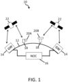
- FIG. 1 An illustrative communications system with satellites is shown in FIG. 1 .
- system 10 may include one or more constellations of communications satellites 22.
- Satellites 22 may be placed in any/all of low earth orbit (LEO) (e.g., at altitudes of 500-1500 km or other suitable altitudes), geosynchronous orbit, and/or medium earth orbit (MEO) around the Earth 12. Satellites 22 may form a satellite constellation having one or more sets of satellites with different types of orbits, e.g., that are synchronized with each other to provide user populations (or geographic regions) with desired amounts of coverage. There may be any suitable number of satellites 22 in the satellite constellation(s) of system 10 (e.g., 10-100, 1,000-10,000, more than 100, more than 1000, fewer than 10,000, etc.).
- LEO low earth orbit
- MEO medium earth orbit
- Satellites 22 may deliver wireless services to equipment, such as electronic devices 18.
- Electronic devices 18 may include handheld devices and/or other mobile devices such as cellular telephones, tablet computers, laptop computers, wristwatches and other wearable devices, mobile terminals, drones, robots, and other portable electronic devices.
- Electronic devices 18 may include one or more relatively small antennas (see, e.g., antenna 20A, which may be included in an electronic device 18 or may be coupled (directly or indirectly) to an electronic device 18).
- electronic devices 18 may include less portable equipment, such as a set-top box, router, home base station or other such device, and may have one or more larger antennas (see, e.g., antenna 20B, which may be included in or otherwise associated with electronic equipment, e.g., in a home or office).
- Electronic devices 18 may be located anywhere on or above the Earth, e.g., on land, at sea, or in the air.
- the services provided by satellites 22 may include telephone (voice) service, broadband internet access, media distribution services such as satellite audio (satellite radio and/or streaming audio services) and satellite television (video), data communications, location, and/or other services.
- System 10 may include one or more network operations centers (NOCs) such as NOC 16, which can be coupled to one or more gateways, e.g., gateways 14.
- NOCs network operations centers
- Gateways 14 may have transceivers that allow the gateways to transmit wireless signals to satellites 22 over wireless links 20 and that allow the gateways to receive wireless signals from satellites 22 over wireless links 20.
- Wireless links 20 may also be used to support communications between satellites 22 and electronic devices 18.
- a gateway 14 may send traffic over an uplink (one of links 20) to a given satellite 22 that is then routed via a downlink (one of links 20) to one or more electronic devices 18.
- Gateways 14 may perform a variety of services, including supplying media for electronic devices 18, routing telephone calls (e.g., voice and/or video calls) between electronic devices 18 and/or other equipment, providing electronic devices 18 with internet access, and/or delivering other communications and/or data services to electronic devices 18.
- Gateways 14 may communicate with each other via satellites 22 and/or using ground-based communications networks.
- NOC 16 may be used to manage the operations of one or more gateways 14 and/or the operations of one or more satellites 22. For example, NOC 16 may monitor network performance and take appropriate corrective actions if warranted. During these operations, NOC 16 may update software for one or more satellites 22 and/or electronic devices 18, may adjust satellite 22 altitude and/or other orbital parameters, may direct one or more satellites 22 to perform operations to adjust satellite solar panels and/or other satellite components, and/or may otherwise control and maintain one or more of the satellites 22 in the constellation of satellites orbiting the Earth 12. Further, in some embodiments, NOC 16 also may be configured to perform maintenance operations on one or more gateways 14.
- Gateways 14, satellites 22, NOC 16, and electronic devices 18 may be configured to support encrypted communications.
- NOC 16 and gateways 14 may communicate using encrypted communications.
- gateways 14, satellites 22, and electronic devices 18 may communicate using encrypted communications. This allows NOC 16 to issue secure commands and to receive secure information when communicating with gateways 14, satellites 22, and/or electronic devices 18.
- the use of encrypted communications within system 10 also allows electronic devices 18 to securely communicate with each other and with gateways 14, and also allows gateways 14 to securely distribute media and/or other information to electronic devices 18, e.g., in compliance with digital protection requirements.
- satellites 22 may serve as orbiting relay stations. For example, when a gateway 14 transmits a wireless uplink signal, one or more satellites 22 may forward these signals as downlink signals to one or more electronic devices 18. In some embodiments, some electronic devices 18 may be receive-only devices while other electronic devices 18 may support bidirectional communications with satellites. In scenarios in which an electronic device 18 supports bidirectional communications, an electronic device 18 may transmit wireless signals to one or more satellites 22, so that the one or more satellites 22 may relay this information to one or more appropriate destinations (e.g., gateways 14, other electronic devices 18, etc.).
- appropriate destinations e.g., gateways 14, other electronic devices 18, etc.
- Satellites 22 may support any suitable satellite communications bands (e.g, IEEE bands) such as the L-band (1-2 GHz), S-band (2-4 GHz), C-band (4-8 GHz), Ka-band (27-40 GHz), V-band (40-75 GHz), W-band (75-110 GHz), and/or other bands suitable for space communications (e.g., frequencies above 1 GHz, below 110 GHz, and/or other suitable frequencies).
- suitable satellite communications bands e.g, IEEE bands
- L-band 1-2 GHz
- S-band 2-4 GHz
- C-band (4-8 GHz) such as the L-band (1-2 GHz), S-band (2-4 GHz), C-band (4-8 GHz), Ka-band (27-40 GHz), V-band (40-75 GHz), W-band (75-110 GHz), and/or other bands suitable for space communications (e.g., frequencies above 1 GHz, below 110 GHz, and/or other suitable frequencies).
- Some frequencies may penetrate buildings and may therefore be suitable for communicating with electronic devices located indoors at least some of the time, e.g., handheld electronic devices 18 (e.g., devices that are mobile and that may sometimes be indoors and may sometimes be outdoors) and/or electronic devices 18 without an external antenna/receiver.
- Other frequencies e.g., V-band frequencies and other high frequencies such as Ka-band and W-band frequencies
- satellites 22 may, for example, include C-band satellites (or other low band satellites such as L-band or S-band satellites), V-band satellites (or other high band satellites such as Ka-band or W-band satellites) and/or dual-band satellites (e.g., satellites that that support C-band and V-band communications or other low and high band communications).
- C-band satellites or other low band satellites such as L-band or S-band satellites
- V-band satellites or other high band satellites such as Ka-band or W-band satellites
- dual-band satellites e.g., satellites that that support C-band and V-band communications or other low and high band communications.
- Satellites 22 may use any suitable types of antennas (e.g., phased antenna arrays, fixed direct radiating arrays, deployable direct radiating antenna arrays, space fed arrays, reflector fed arrays, etc.).
- Antenna arrays based on space fed arrays that can be collapsed into a flat stowed profile when being delivered to space may sometimes be described herein as an example.
- a collapsible space fed array (sometimes referred to as a space fed lens array) is used to feed a direct radiating array.
- the direct radiating array and the space fed array operate at different satellite bands band.
- upconversion and downconversion circuitry may be used to convert between the frequency of operation of the space fed array (V-band in this example) and the frequency of operation of the direct radiating array (C-band in this example).
- V-band the frequency of operation of the space fed array
- C-band frequency of operation of the direct radiating array
- the size of the space fed array may be reduced (because a V-band space fed array may occupy less space than a C-band space fed array).
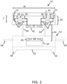
- FIG. 2 presents a side view of an illustrative satellite with a collapsible (e.g., foldable) space fed array.
- satellite 22 may have a housing structure such as bus 52.
- Bus 52 may have a main portion 54, which can include fixed or detachable downwardly extending legs 56.
- the shape of bus 52 may be relatively flat (e.g., planar and relatively thin when viewed from the side) with a polygonal outline or other suitable outline (e.g., a hexagonal or octagonal footprint when viewed from above).
- the flat shape of bus 52 may facilitate stacking.
- Solar panels 58 may extend from the sides of bus 52 and may be used to power bus 52.
- Bus 52 may be provided with any/all of a chemical propulsion system, an electrical propulsion system (e.g., a set of 4-8 thrusters each with an associated tank of an ionized fluid), a hybrid propulsion system, and/or other suitable propulsion system(s).
- a chemical propulsion system e.g., a set of 4-8 thrusters each with an associated tank of an ionized fluid
- a hybrid propulsion system e.g., a set of 4-8 thrusters each with an associated tank of an ionized fluid
- other suitable propulsion system(s) e.g., a set of 4-8 thrusters each with an associated tank of an ionized fluid
- Direct radiating antenna array (direct radiating array) 30 may have an array of antenna elements 32 (e.g., 10s of elements, 100s of elements, or other suitable number of elements). Circuitry 34 may be used to couple (communicatively) array 30 to inner array 42. Inner array 42 may have an array of antenna elements 44 (e.g., 10s of elements, 100s of elements, or other suitable number of elements). Each of elements 44 may be coupled (communicatively) to a respective one of elements 32 using circuitry 34.
- antenna elements 32 e.g., 10s of elements, 100s of elements, or other suitable number of elements.
- Circuitry 34 may be used to couple (communicatively) array 30 to inner array 42.
- Inner array 42 may have an array of antenna elements 44 (e.g., 10s of elements, 100s of elements, or other suitable number of elements). Each of elements 44 may be coupled (communicatively) to a respective one of elements 32 using circuitry 34.
- Circuitry 34 may include any/all of integrated circuits, discrete components, transmission line structures, and/or other circuitry on one or more substrates, such as one or more printed circuit boards.
- a heat sink structure may be used to radiate excess heat.
- the circuit components of circuitry 34 may include amplifiers, such as amplifiers 36, upconversion circuitry such as upconverters 38 (e.g., C-band to V-band upconverters), and downconversion circuitry such as downconverters 41 (e.g., V-band to C-band downconverters).
- Each downconverter 41 may be embedded in a chain of amplifiers (e.g., power amplifiers) that provides signals from a given one of elements 44 in inner array 42 to a corresponding element 32 in direct radiating array 30.
- the signals provided by downconverters 41 are downconverted versions of the signals received by inner array 42.
- Each upconverter 38 may be embedded in a chain of amplifiers 36 (e.g., low noise amplifiers) that provides signals from a given one of elements 32 in direct radiating array 30 to a corresponding element 44 in inner array 42.
- the signals provided by upconverters 38 are upconverted versions of the signals received by array 30.
- Space fed array 40 includes inner array 42 and feed array 46.
- Feed array 46 may include an array of antenna elements 48 (e.g., 10s of elements, 100s of elements, or other suitable number of elements).
- Feed array 46 may be coupled to phased antenna array feed circuitry such as beamforming and signal routing circuitry 50.
- Circuitry 50 may be used to feed one or more antenna elements 48 in feed array 46.
- digital and analog beamforming operations may be performed by circuitry 50.
- Space fed array 40 and direct radiating array 30 serve as a radio-frequency lens that projects outgoing wireless signals from feed array 46 onto a desired location on the Earth and that routes incoming signals from Earth onto appropriate antenna elements 48 of feed array 46.
- the signal routing circuitry in circuitry 50 may include, for example, a 1000 x 1000 switch or other suitable switching circuitry for routing uplinks to downlinks.
- Band management (channelizer) functions may be supported using circuitry 50.
- Circuitry 50 and the antenna arrays of satellite 22 may be used to handle up to thousands or tens of thousands of individual wireless (e.g., beams associated with individual electronic devices 18 and/or groups of electronic devices 18, gateways 14, etc.).
- Deployment actuators 60 may form support posts and may include electrically controlled actuators, power transfer cables, shielding, and other structures. When extended as shown in FIG. 2 , deployment structures 60 separate inner array 42 from feed array 46. The separation between inner array 42 and feed array 46 may be, for example, approximately 2 meters. However, an appropriate (effective) separation distance can be selected based on the inner array 42 and feed array 46 configuration. When transporting satellite 22 to orbit, structures 60 may be retracted (e.g., in the -Z direction) into bus 52 to stow antenna arrays 30 and 42 in a compact arrangement.
- the size of satellite 22 and/or its associated antenna space fed arrays may be reduced by converting signals between bands using circuitry 34.
- the width (diameter) W of a C-band array (direct radiating array 30) may be fairly large (e.g., 8-11 meters, more than 6 m, more than 8 m, less than 10 m, less than 15 m, etc.).
- the widths (diameters) of feed array 46 and inner array 42 would need to be enlarged accordingly.
- space-fed array 40 may operate at V-band frequencies and can be relatively compact (e.g., 1-5 m in diameter, less than 5 m in diameter, less than 3 m in diameter, more than 0.5 m in diameter, etc.). Configurations in which direct radiating array 30 of satellite 22 supports only V-band operations may also be used.
- direct radiating array 30 may be implemented as a V-band array with a relatively compact width (diameter) W (e.g., a width that is comparable to the width of inner array 42 of V-band space-fed array 40.
- W e.g., a width that is comparable to the width of inner array 42 of V-band space-fed array 40.
- upconverters 38 and downconverters 41 may be omitted.
- some of satellites 22 in system 10 ( FIG. 1 ) may be C/V-band satellites of the type shown in FIG. 2 and other satellites 22 in system 10 may be V-band satellites, e.g., as shown in FIG. 3 .
- the same type of space fed array (see, e.g., array 40 of FIGS. 2 and 3 ) may be used in both types of satellite, thereby reducing system complexity.
- the antenna elements that form the antenna arrays of satellites 22 may be any/all of horn antennas, slot antennas, patch antennas, monopoles, dipoles, antennas that use other types of antenna resonating elements and/or that use combinations of these antenna elements. In arrangements where a relatively large array is involved, it may be desirable to form an array from a set of interlocking antenna array panels (tiles). Satellites such as satellite 22 of FIG. 3 that operate only in higher bands (e.g., the V-band in this example) may use antenna structures (e.g., arrays 30) with smaller widths W than satellites such as satellites 22 of FIG. 2 that has a direct radiating array 30 that operates at C-band frequencies. Accordingly, direct radiating array 30 of satellite 22 of FIG. 3 may have an antenna array panel stack formed from a single panel or relatively small number of panels, and this stack will be shorter than an antenna array panel stack formed from the larger number of panels for a corresponding direct radiating array 30 of satellite 22 of FIG. 2 .
- Satellites 22 may be stacked vertically when loaded into a payload fairing of a launch vehicle. To accommodate antenna array panel stacks of different heights in a nested stack that includes satellites 22 with different types of antenna arrays, satellites 22 may have individualized buses. Each bus 52 may be individualized depending on its location in the stack of buses in the fairing and/or based on the payload type of the bus underneath that bus.
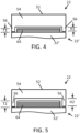
- satellite 22 has bus 52 with main portion 54 and legs 56.
- Underlying satellite 22' has a bus 52' with a relatively short antenna array panel stack 64.
- Short panel stack 64 may have a height T1 and may, for example, be associated with a satellite of the type shown in FIG. 3 (e.g., a V-band satellite).
- bus 52 of satellite 22 may have short legs 56 of height H1.
- bus 52 may also include an array of stowed solar panels, which also can be factored when determining the length of legs 56 and the separation height H1.
- satellite 22 has a bus such as bus 52 with relatively tall legs 56 of height H2, so that there is sufficient space under satellite 22 to accommodate a tall antenna array panel stack 64 on satellite bus 52' of satellite 22'.
- Tall stack 64 of FIG. 5 has a height T2 that is larger than T1 (e.g., stack 64 of FIG. 5 may contain more antenna array panels for supporting C-band operations). Because height T2 is less than H2, stack 64 can be accommodated in the space under satellite 22.
- Legs 56 on each bus 52 may, if desired, be customized based on the position of that bus 52 within a stack of nested buses 52 in a payload fairing (e.g., based on vertical location Z of FIG. 6 ). As shown in FIG. 6 , for example, legs 56 may have different shapes, different sizes, and/or different strengths, depending on the vertical location Z. The different configurations for legs 56 may be selected so that legs 56 are stronger (e.g., bigger or made from a stronger material) at lower positions (smaller Z values) and are progressively weaker (e.g., smaller or made from a lighter material) at higher positions (larger Z values).
- Satellites at the top of the stack can be formed with lighter and smaller legs than the lower-level satellites because fewer satellites are stacked above, thereby saving overall payload weight.
- the composition of the legs 56 for each bus in a stack can be selected based on the load the legs 56 will need to sustain during launch. For example, during launch, the load experienced by a bus at or near the bottom of the stack (e.g., bus 52-1) will be greater than the load experienced by a bus at or near the top of the stack (e.g., bus 52-4).
- each leg 56 can be selected in accordance with the load (e.g., the maximum load) it will experience during launch.
- Legs 56 can vary in size, shape, thickness, density, composition, height, etc. to provide for stronger legs 56 on buses 52 near the bottom of the stack and lighter (and possibly less expensive) legs 56 on buses near the top of the stack.
- the height of legs 56 also can be selected based on the necessary separation from the bus immediately below, e.g., based on stowed antenna and/or solar arrays. In at least some embodiments, a limited number of legs 56 will be available as options to accommodate different height and strength needs, while still satisfying economies of scale (e.g., not every leg 56 needs to be customized).
- FIG. 7 shows how main bus portion 54 may be formed from peripheral wall panels 70 supported by a network of internal panels 72.
- Ring-shaped planar upper panel 76 may be attached to the top of panels 70 and 72 and planar lower panel 74 may be attached to the bottom of panels 70 and 72 to form bus 52.
- Legs 56 may be formed from variable-length corner fittings attached to perimeter panels 70 (e.g., corner fittings that are attached to panels 70 using welds, screws or other fasteners, adhesive, or other attachment mechanisms).
- the structures of FIG. 7 may be formed from any/all of metal, polymer (e.g., fiber-composite materials), and/or other suitable materials. In the example of FIG.
- bus 52 has an octagonal outline (i.e., an octagonal footprint when viewed from above). If desired, bus 52 may be configured to have a hexagonal outline, other polygonal outlines, or other shapes. The example of FIG. 7 is merely illustrative.
- one or more panels may be stacked under bus 52 prior to deployment in space.
- Antenna arrays 78 e.g., panels for direct radiating array 30
- Deployment arm 80 may be used to move solar panels 58 from the stowed configuration of FIG. 8 to a deployed configuration in which solar panels 58 extend from the sides of bus 52 (see, e.g., FIGS. 2 and 3 ).
- Springs, hinges, stop structures, and other mechanisms may be used to help deploy panels 58 in desired shapes (e.g., in two long arms extending from opposing sides of bus 52 or other suitable solar panel array shapes).
- Panels 58 may be polygonal (hexagonal, octagonal, rectangular, etc.) or may have other suitable shapes.
- antenna arrays 78 are in a stowed configuration.
- FIG. 9 shows how antenna arrays 78 of FIG. 8 in a deployed configuration.
- deployment actuators 60 can be extended to move the antenna arrays 78 (along with any other associated hardware) away from bus 52.
- FIG. 10 is a perspective view of satellite 22 in a configuration in which antenna arrays 78 include a small direct radiating array 30 (e.g., a V-band array).
- FIG. 11 presents a side view of satellite 22 of FIG. 10 , in which solar panels 58 and antenna arrays 78 have been stowed, e.g., prior to stacking satellite 22 with other satellites in payload fairing 80 ( FIG. 12 ).
- Satellites 22 may be nested on top of one another using legs 56 (and possibly other structures) to achieve separation.
- One or more characteristics of the legs 56 e.g., height, strength, shape, size, composition, etc.
- One or more characteristics of the legs 56 can be selected with reference to the position of satellite 52 within the nested stack.
- Each satellite 22 may, if desired, have individually selected legs that have a height chosen to accommodate the thickness of the payload of the satellite bus directly under that satellite and/or a strength (or load-bearing capability) to accommodate the load the bus 52 will experience, depending on its relative stack position, during launch.
- FIG. 13 presents a perspective view of satellite 22 in a configuration in which antenna arrays 78 have tiled array panels, such as a central hexagonal panel surrounded by six trapezoidal panels to form a polygonal antenna array shape (e.g., for a direct radiating array 30 that supports C-band frequencies, such as direct radiating array 30 of FIG. 2 ).
- FIG. 14 shows how the stack of panels of antenna arrays 78 of FIG. 13 may be thicker (e.g., when nested) than the panel(s) of antenna arrays 78 of satellite 22 of FIG. 11 . Accordingly, a satellite bus 52 above the stack of panels of antenna arrays 78 of FIG. 13 would need to be fitted with longer legs 56 to accommodate the added height.
- FIG. 15 shows how satellites such as satellite 22 of FIG. 14 may be loaded into payload fairing 80 in nested stacks.
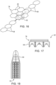
- FIG. 16 is a perspective view of satellite 22 in a configuration in which antenna arrays 78 have tiled hexagonal antenna array panels that form a relatively large antenna array structure (e.g., for a direct radiating array 30 that supports C-band frequencies such as direct radiating array 30 of FIG. 2 ). If desired, the panels of array 30 may be formed from octagonal panels or panels of other shapes. The example of FIG. 16 is merely illustrative.
- FIG. 17 shows how the panels of antenna arrays 78 of FIG. 16 may be stowed. As shown in FIG. 17 , the stowed panels of antenna arrays 78 may be thicker than the panel(s) of antenna arrays 78 of satellite 22 of FIG. 11 .
- FIG. 18 shows how satellites such as satellite 22 of FIG. 18 may be loaded into payload fairing 80 in nested stacks.
- the fairing 80 of FIGS. 12, 15 , and 18 can include only buses 52 having one type of antenna array (e.g., direct radiating array 30) in a homogeneous payload or can include buses 52 having multiple types of antenna arrays (e.g., with different height) in a heterogeneous payload.
- Satellites 22 may be densely packed into fairing 80 by omitting central dispensing mechanisms. In space, each stacked satellite can be serially dispensed using (e.g., passive) dispensing mechanisms such as wireless electrically controllable release devices and passive separation springs. Satellites 22 may be dispensed by releasing the fairing surrounding the stacked satellites, releasing the uppermost stacked satellite (e.g., by releasing a junction between the uppermost and next-to-uppermost satellites in a stack via wireless commands from Earth), waiting for the released satellite to drift away from the stack, and repeating this process until all satellites have been released. The timing of each release can be further selected to facilitate positioning the satellite 22 into its orbit.
- passive dispensing mechanisms such as wireless electrically controllable release devices and passive separation springs. Satellites 22 may be dispensed by releasing the fairing surrounding the stacked satellites, releasing the uppermost stacked satellite (e.g., by releasing a junction between the uppermost and next-to-uppermost satellites
- space fed array 40 of C-band-to-V-band satellite 22 of FIG. 2 may be of the same configuration as space fed array 40 of V-band satellite 22 of FIG. 3 .
- Bus 52 may also be the same or similar when configured for use in satellites 22 of the type shown in FIG. 2 (sometimes referred to as hybrid satellites or retrofit antenna satellites) and when configured for use in satellites 22 of the type shown in FIG. 3 .
- parts of satellites 22 such as a common space fed array and a common bus may be shared.
- the direct radiating array 30 that is mounted on space fed array 40 will be of similar size (and will handle the same satellite band) as inner array 42 in space fed array 40.
- direct radiating array 30 may be larger than inner array 42 of space fed array 40 (e.g., array 30 may be relatively large to handle C-band signals whereas space feed array 40 may have antenna arrays that are more compact and suitable for handling V-band signals).
- Satellites 22 with the equal-size-array configuration and satellites 22 with the hybrid array configuration may be mounted in a common payload fairing for delivery to space and/or may be deployed using separate payload fairings.
- both types of satellites When loaded into the same payload fairing, both types of satellites may be accommodated by adjusting the leg size of legs 56 of satellite buses 52. This allows array panel stacks of different heights to be accommodated in the nested stacks of satellites.
Landscapes
- Engineering & Computer Science (AREA)
- Remote Sensing (AREA)
- Aviation & Aerospace Engineering (AREA)
- Physics & Mathematics (AREA)
- Astronomy & Astrophysics (AREA)
- General Physics & Mathematics (AREA)
- Electromagnetism (AREA)
- Computer Networks & Wireless Communication (AREA)
- Signal Processing (AREA)
- Life Sciences & Earth Sciences (AREA)
- Sustainable Development (AREA)
- Details Of Aerials (AREA)
- Radio Relay Systems (AREA)
- Variable-Direction Aerials And Aerial Arrays (AREA)
Description
- This disclosure relates generally to communications, including to satellite systems and architectures for use in a communications network.
- Communications systems often use satellites to convey data. Satellite-based systems allow information to be conveyed wirelessly over large distances, such as oceans. For example, satellite-based systems can be used to convey information to land-based devices such as handheld equipment and home or office equipment. Further, satellite communications systems can be used to provide coverage where physical infrastructure has not been installed and/or to mobile devices that do not remain attached to an infrastructure resource.
- It can be challenging to implement an effective satellite-based communications system. If care is not taken, satellites may be deployed inefficiently, leading to elevated costs and suboptimal ground coverage. Further, if a satellite-based communications system is designed to serve a period or region of highest demand, resources may remain idle during periods of lower demand and/or over regions with lower demand. Moreover, a conventional satellite-based communication system designed for a particular demand level may not be able to dynamically increase capacity in response to higher demand.
-
US 2009/009391 A1 discloses a satellite with a lightweight space-fed active phased array antenna system.CN 105 151 330 A ,US 2016/304219 A1 ,US 5 386 953 A , andUS 2016/248157 A1 disclose further satellite systems.US 2007/046547 A1 discloses a space-fed active phased array antenna system. - There is provided a satellite and a method of operating a satellite according to the appended claims.
- A satellite system (or constellation) may have satellites that orbit the Earth and that communicate with ground-based equipment, such as mobile devices and/or equipment situated in a home or office. A satellite includes a satellite bus that supports, among other things, antenna arrays. The antenna arrays include one or more space fed arrays. A space fed array has an antenna feed array and an inner array.
- The inner array of a space fed array is coupled (directly or indirectly) to a direct radiating array. The direct radiating array may operate in the same satellite band as the space fed array or may operate in a different satellite (or other) band. In the claimed configuration in which the satellite is provided with a direct radiating array that operates in a different band than the space fed array, upconversion and downconversion circuitry is coupled between the direct radiating array and the space fed array.
- Beam forming and/or signal routing circuitry may be coupled (directly or indirectly) to the feed array in the space fed array. The beam forming and/or signal routing circuitry and the antenna feed array may be housed within a satellite bus having peripheral walls attached to corner fittings. The corner fittings can be customized to provide the satellite bus with customized leg lengths, shapes, and strengths. This may help in forming nested stacks of satellites in a payload fairing and in accommodating stacked satellites with different types of antenna arrays.
-
-
FIG. 1 presents a diagram of an example communications system with satellites, in accordance with some embodiments. -
FIG. 2 presents a side view of an illustrative satellite having a direct radiating array and an inner array that have different sizes and that may operate using different bands, in accordance with some embodiments. -
FIG. 3 presents a side view of an illustrative satellite having a direct radiating array and an inner array that may handle satellite signals in a common satellite band, in accordance with some embodiments. -
FIG. 4 presents a side view of an illustrative satellite bus having short legs to accommodate a short payload on an underlying satellite bus, in accordance with some embodiments. -
FIG. 5 presents a side view of an illustrative satellite bus having tall legs to accommodate a tall payload on an underlying satellite bus, in accordance with some embodiments. -
FIG. 6 presents a side view of a portion of a stack of satellite buses having support structures, such as legs that vary in shape, size, and/or strength as a function of position within the stack, in accordance with some embodiments. -
FIG. 7 presents a diagram showing structures that may be used in forming a satellite bus, in accordance with some embodiments. -
FIG. 8 presents a side view of an illustrative satellite with an antenna array in a stowed configuration, in accordance with some embodiments. -
FIG. 9 presents a side view of the illustrative satellite ofFIG. 8 with the antenna array in a deployed configuration, in accordance with some embodiments. -
FIG. 10 presents a perspective view of an illustrative satellite with a direct radiating array and an inner array of comparable sizes, in accordance with some embodiments. -
FIG. 11 presents a side view of the illustrative satellite ofFIG. 10 with its antenna arrays in a stowed configuration, in accordance with some embodiments. -
FIG. 12 presents a cross-sectional side view of an illustrative spacecraft payload fairing loaded with satellites of the type shown inFIGS. 10 and 11 , in accordance with some embodiments. -
FIG. 13 presents a perspective view of an illustrative satellite with a direct radiating array that is larger than an inner array, in accordance with some embodiments. -
FIG. 14 presents a side view of the satellite ofFIG. 13 with its antenna arrays in a stowed configuration, in accordance with some embodiments. -
FIG. 15 presents a cross-sectional side view of a spacecraft payload fairing loaded with satellites of the type shown inFIGS. 13 and 14 , in accordance with some embodiments. -
FIG. 16 presents a perspective view of an illustrative satellite with a tiled direct radiating array that is larger than an inner array, in accordance with some embodiments. -
FIG. 17 presents a side view of the satellite ofFIG. 16 with its antenna arrays in a stowed configuration, in accordance with some embodiments. -
FIG. 18 presents a cross-sectional side view of a spacecraft payload fairing loaded with satellites of the type shown inFIGS. 16 and 17 , in accordance with some embodiments. - The present disclosure, including the accompanying drawings, is illustrated by way of examples and not by way of limitation.
- A communications network may include one or more communications satellites and other equipment, including ground-based communications equipment and user terminals (or user equipment (UE)). One or more of the satellites may be used to deliver wireless services, e.g., to portable electronic devices, home and/or office equipment, and other equipment. For example, wireless services can be provided to handheld devices, wearable devices, set-top boxes, media devices, mobile terminals, computing devices, sensors, etc. An illustrative communications system with satellites is shown in
FIG. 1 . As shown inFIG. 1 ,system 10 may include one or more constellations ofcommunications satellites 22.Satellites 22 may be placed in any/all of low earth orbit (LEO) (e.g., at altitudes of 500-1500 km or other suitable altitudes), geosynchronous orbit, and/or medium earth orbit (MEO) around the Earth 12.Satellites 22 may form a satellite constellation having one or more sets of satellites with different types of orbits, e.g., that are synchronized with each other to provide user populations (or geographic regions) with desired amounts of coverage. There may be any suitable number ofsatellites 22 in the satellite constellation(s) of system 10 (e.g., 10-100, 1,000-10,000, more than 100, more than 1000, fewer than 10,000, etc.). -
Satellites 22 may deliver wireless services to equipment, such aselectronic devices 18.Electronic devices 18 may include handheld devices and/or other mobile devices such as cellular telephones, tablet computers, laptop computers, wristwatches and other wearable devices, mobile terminals, drones, robots, and other portable electronic devices.Electronic devices 18 may include one or more relatively small antennas (see, e.g.,antenna 20A, which may be included in anelectronic device 18 or may be coupled (directly or indirectly) to an electronic device 18). Further,electronic devices 18 and may include less portable equipment, such as a set-top box, router, home base station or other such device, and may have one or more larger antennas (see, e.g.,antenna 20B, which may be included in or otherwise associated with electronic equipment, e.g., in a home or office).Electronic devices 18 may be located anywhere on or above the Earth, e.g., on land, at sea, or in the air. The services provided bysatellites 22 may include telephone (voice) service, broadband internet access, media distribution services such as satellite audio (satellite radio and/or streaming audio services) and satellite television (video), data communications, location, and/or other services. -
System 10 may include one or more network operations centers (NOCs) such as NOC 16, which can be coupled to one or more gateways, e.g.,gateways 14. There may be any suitable number ofgateways 14 in system 10 (e.g., 1-100, more than 10, more than 100, fewer than 1000, etc.).Gateways 14 may have transceivers that allow the gateways to transmit wireless signals tosatellites 22 over wireless links 20 and that allow the gateways to receive wireless signals fromsatellites 22 over wireless links 20. Wireless links 20 may also be used to support communications betweensatellites 22 andelectronic devices 18. During media distribution operations, for example, agateway 14 may send traffic over an uplink (one of links 20) to a givensatellite 22 that is then routed via a downlink (one of links 20) to one or moreelectronic devices 18.Gateways 14 may perform a variety of services, including supplying media forelectronic devices 18, routing telephone calls (e.g., voice and/or video calls) betweenelectronic devices 18 and/or other equipment, providingelectronic devices 18 with internet access, and/or delivering other communications and/or data services toelectronic devices 18.Gateways 14 may communicate with each other viasatellites 22 and/or using ground-based communications networks. -
NOC 16 may be used to manage the operations of one ormore gateways 14 and/or the operations of one ormore satellites 22. For example,NOC 16 may monitor network performance and take appropriate corrective actions if warranted. During these operations,NOC 16 may update software for one ormore satellites 22 and/orelectronic devices 18, may adjustsatellite 22 altitude and/or other orbital parameters, may direct one ormore satellites 22 to perform operations to adjust satellite solar panels and/or other satellite components, and/or may otherwise control and maintain one or more of thesatellites 22 in the constellation of satellites orbiting theEarth 12. Further, in some embodiments,NOC 16 also may be configured to perform maintenance operations on one ormore gateways 14. -
Gateways 14,satellites 22,NOC 16, andelectronic devices 18 may be configured to support encrypted communications. For example,NOC 16 andgateways 14 may communicate using encrypted communications. Similarly,gateways 14,satellites 22, andelectronic devices 18 may communicate using encrypted communications. This allowsNOC 16 to issue secure commands and to receive secure information when communicating withgateways 14,satellites 22, and/orelectronic devices 18. The use of encrypted communications withinsystem 10 also allowselectronic devices 18 to securely communicate with each other and withgateways 14, and also allowsgateways 14 to securely distribute media and/or other information toelectronic devices 18, e.g., in compliance with digital protection requirements. - During operation of
system 10,satellites 22 may serve as orbiting relay stations. For example, when agateway 14 transmits a wireless uplink signal, one ormore satellites 22 may forward these signals as downlink signals to one or moreelectronic devices 18. In some embodiments, someelectronic devices 18 may be receive-only devices while otherelectronic devices 18 may support bidirectional communications with satellites. In scenarios in which anelectronic device 18 supports bidirectional communications, anelectronic device 18 may transmit wireless signals to one ormore satellites 22, so that the one ormore satellites 22 may relay this information to one or more appropriate destinations (e.g.,gateways 14, otherelectronic devices 18, etc.). -
Satellites 22 may support any suitable satellite communications bands (e.g, IEEE bands) such as the L-band (1-2 GHz), S-band (2-4 GHz), C-band (4-8 GHz), Ka-band (27-40 GHz), V-band (40-75 GHz), W-band (75-110 GHz), and/or other bands suitable for space communications (e.g., frequencies above 1 GHz, below 110 GHz, and/or other suitable frequencies). Illustrative configurations in whichsatellites 22 support C and/or V bands may sometimes be described herein as an example, but other bands can be used as desired. - Some frequencies (e.g., C-band frequencies and other low frequencies such as L-band and S-band frequencies) may penetrate buildings and may therefore be suitable for communicating with electronic devices located indoors at least some of the time, e.g., handheld electronic devices 18 (e.g., devices that are mobile and that may sometimes be indoors and may sometimes be outdoors) and/or
electronic devices 18 without an external antenna/receiver. Other frequencies (e.g., V-band frequencies and other high frequencies such as Ka-band and W-band frequencies) do not readily (or effectively) penetrate buildings and may therefore be suitable for communicating withelectronic devices 18 that have external antennas/receivers (e.g.,antenna 20B) that are mounted outdoors and/or otherwise have a line-of-sight path tosatellites 22. To accommodate a variety of scenarios, e.g., both mobile device scenarios and home/office scenarios,satellites 22 may, for example, include C-band satellites (or other low band satellites such as L-band or S-band satellites), V-band satellites (or other high band satellites such as Ka-band or W-band satellites) and/or dual-band satellites (e.g., satellites that that support C-band and V-band communications or other low and high band communications). -
Satellites 22 may use any suitable types of antennas (e.g., phased antenna arrays, fixed direct radiating arrays, deployable direct radiating antenna arrays, space fed arrays, reflector fed arrays, etc.). Antenna arrays based on space fed arrays that can be collapsed into a flat stowed profile when being delivered to space may sometimes be described herein as an example. - In at least some embodiments, a collapsible space fed array (sometimes referred to as a space fed lens array) is used to feed a direct radiating array. The direct radiating array and the space fed array operate at different satellite bands band. In configurations in which the direct radiating array operates at C-band frequencies, upconversion and downconversion circuitry may be used to convert between the frequency of operation of the space fed array (V-band in this example) and the frequency of operation of the direct radiating array (C-band in this example). By converting C-band signals to V-band for the space fed array, the size of the space fed array may be reduced (because a V-band space fed array may occupy less space than a C-band space fed array).
-
FIG. 2 presents a side view of an illustrative satellite with a collapsible (e.g., foldable) space fed array. As shown inFIG. 2 ,satellite 22 may have a housing structure such asbus 52.Bus 52 may have amain portion 54, which can include fixed or detachable downwardly extendinglegs 56. The shape ofbus 52 may be relatively flat (e.g., planar and relatively thin when viewed from the side) with a polygonal outline or other suitable outline (e.g., a hexagonal or octagonal footprint when viewed from above). The flat shape ofbus 52 may facilitate stacking.Solar panels 58 may extend from the sides ofbus 52 and may be used topower bus 52.Bus 52 may be provided with any/all of a chemical propulsion system, an electrical propulsion system (e.g., a set of 4-8 thrusters each with an associated tank of an ionized fluid), a hybrid propulsion system, and/or other suitable propulsion system(s). - Direct radiating antenna array (direct radiating array) 30 may have an array of antenna elements 32 (e.g., 10s of elements, 100s of elements, or other suitable number of elements).
Circuitry 34 may be used to couple (communicatively)array 30 toinner array 42.Inner array 42 may have an array of antenna elements 44 (e.g., 10s of elements, 100s of elements, or other suitable number of elements). Each ofelements 44 may be coupled (communicatively) to a respective one ofelements 32 usingcircuitry 34. -
Circuitry 34 may include any/all of integrated circuits, discrete components, transmission line structures, and/or other circuitry on one or more substrates, such as one or more printed circuit boards. A heat sink structure may be used to radiate excess heat. The circuit components ofcircuitry 34 may include amplifiers, such asamplifiers 36, upconversion circuitry such as upconverters 38 (e.g., C-band to V-band upconverters), and downconversion circuitry such as downconverters 41 (e.g., V-band to C-band downconverters). Eachdownconverter 41 may be embedded in a chain of amplifiers (e.g., power amplifiers) that provides signals from a given one ofelements 44 ininner array 42 to acorresponding element 32 indirect radiating array 30. The signals provided bydownconverters 41 are downconverted versions of the signals received byinner array 42. Eachupconverter 38 may be embedded in a chain of amplifiers 36 (e.g., low noise amplifiers) that provides signals from a given one ofelements 32 indirect radiating array 30 to acorresponding element 44 ininner array 42. The signals provided byupconverters 38 are upconverted versions of the signals received byarray 30. - Space fed
array 40 includesinner array 42 andfeed array 46.Feed array 46 may include an array of antenna elements 48 (e.g., 10s of elements, 100s of elements, or other suitable number of elements).Feed array 46 may be coupled to phased antenna array feed circuitry such as beamforming andsignal routing circuitry 50.Circuitry 50 may be used to feed one or more antenna elements 48 infeed array 46. During operation, digital and analog beamforming operations may be performed bycircuitry 50. Space fedarray 40 anddirect radiating array 30 serve as a radio-frequency lens that projects outgoing wireless signals fromfeed array 46 onto a desired location on the Earth and that routes incoming signals from Earth onto appropriate antenna elements 48 offeed array 46. The signal routing circuitry incircuitry 50 may include, for example, a 1000 x 1000 switch or other suitable switching circuitry for routing uplinks to downlinks. Band management (channelizer) functions may be supported usingcircuitry 50.Circuitry 50 and the antenna arrays ofsatellite 22 may be used to handle up to thousands or tens of thousands of individual wireless (e.g., beams associated with individualelectronic devices 18 and/or groups ofelectronic devices 18,gateways 14, etc.). -
Deployment actuators 60 may form support posts and may include electrically controlled actuators, power transfer cables, shielding, and other structures. When extended as shown inFIG. 2 ,deployment structures 60 separateinner array 42 fromfeed array 46. The separation betweeninner array 42 andfeed array 46 may be, for example, approximately 2 meters. However, an appropriate (effective) separation distance can be selected based on theinner array 42 andfeed array 46 configuration. When transportingsatellite 22 to orbit,structures 60 may be retracted (e.g., in the -Z direction) intobus 52 tostow antenna arrays - The size of
satellite 22 and/or its associated antenna space fed arrays may be reduced by converting signals betweenbands using circuitry 34. The width (diameter) W of a C-band array (direct radiating array 30) may be fairly large (e.g., 8-11 meters, more than 6 m, more than 8 m, less than 10 m, less than 15 m, etc.). To feeddirect radiating array 30 with a space fed array operating at C-band frequencies, the widths (diameters) offeed array 46 andinner array 42 would need to be enlarged accordingly. With the upconversion / downconversion arrangement ofFIG. 2 , however, space-fedarray 40 may operate at V-band frequencies and can be relatively compact (e.g., 1-5 m in diameter, less than 5 m in diameter, less than 3 m in diameter, more than 0.5 m in diameter, etc.). Configurations in which direct radiatingarray 30 ofsatellite 22 supports only V-band operations may also be used. - As shown in
FIG. 3 , for example, direct radiatingarray 30 may be implemented as a V-band array with a relatively compact width (diameter) W (e.g., a width that is comparable to the width ofinner array 42 of V-band space-fedarray 40. In this type of arrangement,upconverters 38 anddownconverters 41 may be omitted. If desired, some ofsatellites 22 in system 10 (FIG. 1 ) may be C/V-band satellites of the type shown inFIG. 2 andother satellites 22 insystem 10 may be V-band satellites, e.g., as shown inFIG. 3 . The same type of space fed array (see, e.g.,array 40 ofFIGS. 2 and3 ) may be used in both types of satellite, thereby reducing system complexity. - The antenna elements that form the antenna arrays of
satellites 22 may be any/all of horn antennas, slot antennas, patch antennas, monopoles, dipoles, antennas that use other types of antenna resonating elements and/or that use combinations of these antenna elements. In arrangements where a relatively large array is involved, it may be desirable to form an array from a set of interlocking antenna array panels (tiles). Satellites such assatellite 22 ofFIG. 3 that operate only in higher bands (e.g., the V-band in this example) may use antenna structures (e.g., arrays 30) with smaller widths W than satellites such assatellites 22 ofFIG. 2 that has adirect radiating array 30 that operates at C-band frequencies. Accordingly, direct radiatingarray 30 ofsatellite 22 ofFIG. 3 may have an antenna array panel stack formed from a single panel or relatively small number of panels, and this stack will be shorter than an antenna array panel stack formed from the larger number of panels for a correspondingdirect radiating array 30 ofsatellite 22 ofFIG. 2 . -
Satellites 22 may be stacked vertically when loaded into a payload fairing of a launch vehicle. To accommodate antenna array panel stacks of different heights in a nested stack that includessatellites 22 with different types of antenna arrays,satellites 22 may have individualized buses. Eachbus 52 may be individualized depending on its location in the stack of buses in the fairing and/or based on the payload type of the bus underneath that bus. - Consider, as an example, the arrangement of
FIG. 4 . In theFIG. 4 example,satellite 22 hasbus 52 withmain portion 54 andlegs 56. Underlying satellite 22' has a bus 52' with a relatively short antennaarray panel stack 64. Short panel stack 64 may have a height T1 and may, for example, be associated with a satellite of the type shown inFIG. 3 (e.g., a V-band satellite). To accommodate height T1, which is relatively short,bus 52 ofsatellite 22 may haveshort legs 56 of height H1. In some embodiments,bus 52 may also include an array of stowed solar panels, which also can be factored when determining the length oflegs 56 and the separation height H1. - As another example, consider the arrangement of
FIG. 5 . In theFIG. 5 example,satellite 22 has a bus such asbus 52 with relativelytall legs 56 of height H2, so that there is sufficient space undersatellite 22 to accommodate a tall antennaarray panel stack 64 on satellite bus 52' of satellite 22'.Tall stack 64 ofFIG. 5 has a height T2 that is larger than T1 (e.g., stack 64 ofFIG. 5 may contain more antenna array panels for supporting C-band operations). Because height T2 is less than H2, stack 64 can be accommodated in the space undersatellite 22. -
Legs 56 on eachbus 52 may, if desired, be customized based on the position of thatbus 52 within a stack of nestedbuses 52 in a payload fairing (e.g., based on vertical location Z ofFIG. 6 ). As shown inFIG. 6 , for example,legs 56 may have different shapes, different sizes, and/or different strengths, depending on the vertical location Z. The different configurations forlegs 56 may be selected so thatlegs 56 are stronger (e.g., bigger or made from a stronger material) at lower positions (smaller Z values) and are progressively weaker (e.g., smaller or made from a lighter material) at higher positions (larger Z values). This helps ensure that the satellites at the lower portions of a satellite stack will not be damaged due to excessive weight from satellites stacked above. Satellites at the top of the stack can be formed with lighter and smaller legs than the lower-level satellites because fewer satellites are stacked above, thereby saving overall payload weight. The composition of thelegs 56 for each bus in a stack can be selected based on the load thelegs 56 will need to sustain during launch. For example, during launch, the load experienced by a bus at or near the bottom of the stack (e.g., bus 52-1) will be greater than the load experienced by a bus at or near the top of the stack (e.g., bus 52-4). Since the load during launch is greater than that experienced prior to launch, eachleg 56 can be selected in accordance with the load (e.g., the maximum load) it will experience during launch.Legs 56 can vary in size, shape, thickness, density, composition, height, etc. to provide forstronger legs 56 onbuses 52 near the bottom of the stack and lighter (and possibly less expensive)legs 56 on buses near the top of the stack. Further, the height oflegs 56 also can be selected based on the necessary separation from the bus immediately below, e.g., based on stowed antenna and/or solar arrays. In at least some embodiments, a limited number oflegs 56 will be available as options to accommodate different height and strength needs, while still satisfying economies of scale (e.g., not everyleg 56 needs to be customized). -
FIG. 7 shows howmain bus portion 54 may be formed fromperipheral wall panels 70 supported by a network ofinternal panels 72. Ring-shaped planarupper panel 76 may be attached to the top ofpanels lower panel 74 may be attached to the bottom ofpanels bus 52.Legs 56 may be formed from variable-length corner fittings attached to perimeter panels 70 (e.g., corner fittings that are attached topanels 70 using welds, screws or other fasteners, adhesive, or other attachment mechanisms). The structures ofFIG. 7 may be formed from any/all of metal, polymer (e.g., fiber-composite materials), and/or other suitable materials. In the example ofFIG. 7 ,bus 52 has an octagonal outline (i.e., an octagonal footprint when viewed from above). If desired,bus 52 may be configured to have a hexagonal outline, other polygonal outlines, or other shapes. The example ofFIG. 7 is merely illustrative. - As shown in the side view of
FIG. 8 , one or more panels, such assolar panels 58, may be stacked underbus 52 prior to deployment in space. Antenna arrays 78 (e.g., panels for direct radiating array 30) may be stored on top of bus 52 (e.g., by retracting deployment actuators 60).Deployment arm 80 may be used to movesolar panels 58 from the stowed configuration ofFIG. 8 to a deployed configuration in whichsolar panels 58 extend from the sides of bus 52 (see, e.g.,FIGS. 2 and3 ). Springs, hinges, stop structures, and other mechanisms may be used to help deploypanels 58 in desired shapes (e.g., in two long arms extending from opposing sides ofbus 52 or other suitable solar panel array shapes).Panels 58 may be polygonal (hexagonal, octagonal, rectangular, etc.) or may have other suitable shapes. - In the example of
FIG. 8 ,antenna arrays 78 are in a stowed configuration.FIG. 9 shows howantenna arrays 78 ofFIG. 8 in a deployed configuration. For example,deployment actuators 60 can be extended to move the antenna arrays 78 (along with any other associated hardware) away frombus 52. -
FIG. 10 is a perspective view ofsatellite 22 in a configuration in whichantenna arrays 78 include a small direct radiating array 30 (e.g., a V-band array).FIG. 11 presents a side view ofsatellite 22 ofFIG. 10 , in whichsolar panels 58 andantenna arrays 78 have been stowed, e.g., prior to stackingsatellite 22 with other satellites in payload fairing 80 (FIG. 12 ).Satellites 22 may be nested on top of one another using legs 56 (and possibly other structures) to achieve separation. One or more characteristics of the legs 56 (e.g., height, strength, shape, size, composition, etc.) can be selected with reference to the position ofsatellite 52 within the nested stack. Eachsatellite 22 may, if desired, have individually selected legs that have a height chosen to accommodate the thickness of the payload of the satellite bus directly under that satellite and/or a strength (or load-bearing capability) to accommodate the load thebus 52 will experience, depending on its relative stack position, during launch. -
FIG. 13 presents a perspective view ofsatellite 22 in a configuration in whichantenna arrays 78 have tiled array panels, such as a central hexagonal panel surrounded by six trapezoidal panels to form a polygonal antenna array shape (e.g., for adirect radiating array 30 that supports C-band frequencies, such asdirect radiating array 30 ofFIG. 2 ).FIG. 14 shows how the stack of panels ofantenna arrays 78 ofFIG. 13 may be thicker (e.g., when nested) than the panel(s) ofantenna arrays 78 ofsatellite 22 ofFIG. 11 . Accordingly, asatellite bus 52 above the stack of panels ofantenna arrays 78 ofFIG. 13 would need to be fitted withlonger legs 56 to accommodate the added height.FIG. 15 shows how satellites such assatellite 22 ofFIG. 14 may be loaded into payload fairing 80 in nested stacks. -
FIG. 16 is a perspective view ofsatellite 22 in a configuration in whichantenna arrays 78 have tiled hexagonal antenna array panels that form a relatively large antenna array structure (e.g., for adirect radiating array 30 that supports C-band frequencies such asdirect radiating array 30 ofFIG. 2 ). If desired, the panels ofarray 30 may be formed from octagonal panels or panels of other shapes. The example ofFIG. 16 is merely illustrative. -
FIG. 17 shows how the panels ofantenna arrays 78 ofFIG. 16 may be stowed. As shown inFIG. 17 , the stowed panels ofantenna arrays 78 may be thicker than the panel(s) ofantenna arrays 78 ofsatellite 22 ofFIG. 11 .FIG. 18 shows how satellites such assatellite 22 ofFIG. 18 may be loaded into payload fairing 80 in nested stacks. The fairing 80 ofFIGS. 12, 15 , and18 can includeonly buses 52 having one type of antenna array (e.g., direct radiating array 30) in a homogeneous payload or can includebuses 52 having multiple types of antenna arrays (e.g., with different height) in a heterogeneous payload. -
Satellites 22 may be densely packed into fairing 80 by omitting central dispensing mechanisms. In space, each stacked satellite can be serially dispensed using (e.g., passive) dispensing mechanisms such as wireless electrically controllable release devices and passive separation springs.Satellites 22 may be dispensed by releasing the fairing surrounding the stacked satellites, releasing the uppermost stacked satellite (e.g., by releasing a junction between the uppermost and next-to-uppermost satellites in a stack via wireless commands from Earth), waiting for the released satellite to drift away from the stack, and repeating this process until all satellites have been released. The timing of each release can be further selected to facilitate positioning thesatellite 22 into its orbit. - If desired, the same (or nearly the same) space fed array design may be used in
satellites 22 of different configurations. For example, space fedarray 40 of C-band-to-V-band satellite 22 ofFIG. 2 may be of the same configuration as space fedarray 40 of V-band satellite 22 ofFIG. 3 .Bus 52 may also be the same or similar when configured for use insatellites 22 of the type shown inFIG. 2 (sometimes referred to as hybrid satellites or retrofit antenna satellites) and when configured for use insatellites 22 of the type shown inFIG. 3 . - Using this approach, parts of
satellites 22 such as a common space fed array and a common bus may be shared. When configured to operate in a V-band arrangement, thedirect radiating array 30 that is mounted on space fedarray 40 will be of similar size (and will handle the same satellite band) asinner array 42 in space fedarray 40. When configured to operate in a hybrid mode, direct radiatingarray 30 may be larger thaninner array 42 of space fed array 40 (e.g.,array 30 may be relatively large to handle C-band signals whereasspace feed array 40 may have antenna arrays that are more compact and suitable for handling V-band signals). -
Satellites 22 with the equal-size-array configuration andsatellites 22 with the hybrid array configuration may be mounted in a common payload fairing for delivery to space and/or may be deployed using separate payload fairings. When loaded into the same payload fairing, both types of satellites may be accommodated by adjusting the leg size oflegs 56 ofsatellite buses 52. This allows array panel stacks of different heights to be accommodated in the nested stacks of satellites. - The foregoing is merely illustrative and various modifications can be made to the described embodiments within the scope defined by the appended claims.
Claims (14)
- A satellite (22), comprising:a satellite bus (52);antenna arrays coupled to the satellite bus (52), wherein the antenna arrays include a direct radiating array (30) configured to handle signals in a first satellite band and a space fed array (40) configured to handle signals in a second satellite band at higher frequencies than the first satellite band; andupconversion (38) and downconversion (41) circuitry coupled between the direct radiating array (30) and the space fed array (40), wherein the space fed array (40) includes an inner antenna array (42) communicatively coupled to the direct radiating array (30) by the upconversion (38) and downconversion (41) circuitry, the space fed array includes a feed array (46), and the space fed array (40) and the direct radiating array (30) are configured to serve as a radio-frequency lens that projects outgoing wireless signals from the feed array (46) onto a location on Earth and that routes incoming signals from Earth onto appropriate antenna elements (48) of the feed array (46).
- The satellite (22) defined in claim 1 further comprising deployment actuators (60) that separate the feed array (46) from the inner antenna array (42).
- The satellite (22) defined in claim 2 wherein:the direct radiating array (30) comprises first antenna elements (32);the inner antenna array (42) comprises second antenna elements (44);each of the first antenna elements (32) is configured to receive wireless signals from Earth in the first satellite band and is configured to provide corresponding upconverted versions of these signals in the second satellite band to a respective one of the second antenna elements (44) through a respective upconverter in the upconversion (38) and downconversion (41) circuitry; andeach of the second antenna elements (44) is configured to receive wireless signals from the feed array (46) in the second satellite band and is configured to provide corresponding downconverted versions of these signals in the first satellite band to a respective one of the first antenna elements (32) through a respective downconverter in the upconversion (38) and downconversion (41) circuitry.
- The satellite (22) defined in claim 3 wherein the first satellite band comprises a C-band and wherein the wireless signals received from Earth comprise C-band signals.
- The satellite (22) defined in claim 4 wherein the second satellite band comprises a V-band and wherein the wireless signals received from the feed array (46) comprise V-band signals.
- The satellite (22) defined in any of claims 3 to 5 further comprising beamforming and signal routing circuitry (50) in the satellite bus (52) that is coupled to the feed array (46).
- The satellite (22) defined in any preceding claim wherein the satellite bus (52) has a polygonal outline and has legs.
- The satellite (22) defined in claim 7 wherein the satellite bus (52) has peripheral wall panels (70) and has configurable-strength corner fittings coupled to the peripheral wall panels (70) that form the legs.
- The satellite (22) defined in claim 8 further comprising solar panels (58) coupled to the satellite bus (52).
- The satellite (22) defined in any preceding claim wherein the first satellite band comprises a satellite band selected from the group consisting of: a V-band and a W-band.
- The satellite (22) defined in any preceding claim wherein the second satellite band comprises a satellite band selected from the group consisting of: a C-band.
- A method of operating a satellite (22) having a satellite bus (52) and antenna arrays coupled to the satellite bus (52), wherein the antenna arrays include a direct radiating array (30) that handles signals in a first satellite band and a space fed array (40) that handles signals in a second satellite band at higher frequencies than the first satellite band, wherein the satellite comprises upconversion (38) and downconversion (41) circuitry coupled between the direct radiating array (30) and the space fed array (40), wherein the space feed array (40) includes an inner antenna array (42) communicatively coupled to the direct radiating array (30) by the upconversion (38) and downconversion (41) circuitry, and wherein the space fed array (40) includes a feed array (46), the method comprising:forming, using the space fed array (40) and the direct radiating array, a radio-frequency lens;with the radio-frequency lens, projecting outgoing wireless signals from the feed array (46) onto a location on Earth; andwith the radio-frequency lens, routing incoming signals received at the satellite onto appropriate antenna elements (48) of the feed array (46).
- The method of claim 12, wherein the satellite (22) comprises deployment actuators (60) that separate the feed array from the inner antenna array (42).
- The method of claim 13, wherein the direct radiating array (30) comprises first antenna elements (32), the inner antenna array (42) comprises second antenna elements (44), and the method further comprises:with each of the first antenna elements (32), receiving wireless signals from Earth in the first satellite band and providing corresponding upconverted versions of these signals in the second satellite band to a respective one of the second antenna elements (44) through a respective upconverter in the upconversion (38) and downconversion (41) circuitry; andwith each of the second antenna elements (44), receiving wireless signals from the feed array (46) in the second satellite band and providing corresponding downconverted versions of these signals in the first satellite band to a respective one of the first antenna elements (32) through a respective downconverter in the upconversion (38) and downconversion (41) circuitry.
Priority Applications (1)
| Application Number | Priority Date | Filing Date | Title |
|---|---|---|---|
| EP24188427.9A EP4420989A3 (en) | 2017-04-24 | 2018-04-09 | Satellite array architecture |
Applications Claiming Priority (3)
| Application Number | Priority Date | Filing Date | Title |
|---|---|---|---|
| US201762489369P | 2017-04-24 | 2017-04-24 | |
| US15/672,122 US10177460B2 (en) | 2017-04-24 | 2017-08-08 | Satellite array architecture |
| PCT/US2018/026749 WO2018200183A1 (en) | 2017-04-24 | 2018-04-09 | Satellite array architecture |
Related Child Applications (1)
| Application Number | Title | Priority Date | Filing Date |
|---|---|---|---|
| EP24188427.9A Division EP4420989A3 (en) | 2017-04-24 | 2018-04-09 | Satellite array architecture |
Publications (2)
| Publication Number | Publication Date |
|---|---|
| EP3616263A1 EP3616263A1 (en) | 2020-03-04 |
| EP3616263B1 true EP3616263B1 (en) | 2024-08-14 |
Family
ID=63854190
Family Applications (2)
| Application Number | Title | Priority Date | Filing Date |
|---|---|---|---|
| EP18721225.3A Active EP3616263B1 (en) | 2017-04-24 | 2018-04-09 | Satellite array architecture |
| EP24188427.9A Pending EP4420989A3 (en) | 2017-04-24 | 2018-04-09 | Satellite array architecture |
Family Applications After (1)
| Application Number | Title | Priority Date | Filing Date |
|---|---|---|---|
| EP24188427.9A Pending EP4420989A3 (en) | 2017-04-24 | 2018-04-09 | Satellite array architecture |
Country Status (6)
| Country | Link |
|---|---|
| US (5) | US10177460B2 (en) |
| EP (2) | EP3616263B1 (en) |
| CN (2) | CN114614885B (en) |
| AU (1) | AU2018257928B2 (en) |
| BR (1) | BR112019022190A2 (en) |
| WO (1) | WO2018200183A1 (en) |
Families Citing this family (8)
| Publication number | Priority date | Publication date | Assignee | Title |
|---|---|---|---|---|
| CN111056050B (en) * | 2019-10-17 | 2021-07-06 | 北京航空航天大学 | An SMA-spring-driven flywheel re-locking mechanism |
| CN111726338B (en) * | 2020-05-19 | 2021-07-13 | 中国科学院信息工程研究所 | A kind of link flooding attack protection method and device |
| WO2022036276A1 (en) | 2020-08-14 | 2022-02-17 | M.M.A. Design, LLC | Deployable electromagnetic radiation directing surface system with actuators |
| US11990676B2 (en) * | 2020-08-14 | 2024-05-21 | M.M.A. Design, LLC | Deployable electromagnetic radiation directing lens system |
| EP4197061A4 (en) * | 2020-08-14 | 2024-09-18 | M.M.A. Design, LLC | DEPLOYABLE ELECTROMAGNETIC RADIATION ORIENTATION LENS SYSTEM |
| EP4252321A4 (en) * | 2020-11-30 | 2024-11-06 | MacDonald, Dettwiler and Associates Corporation | DIRECT RADIATING ARRAY ("DRA") ANTENNA, METHOD OF ASSEMBLING A DRA ANTENNA, AND SYSTEM FOR MANAGING HEAT GENERATED BY A DRA ANTENNA |
| CN112693627A (en) * | 2021-01-05 | 2021-04-23 | 航天行云科技有限公司 | One-rocket multi-satellite stacked launching method |
| US20260035106A1 (en) * | 2024-08-02 | 2026-02-05 | Macdonald, Dettwiler And Associates Corporation | Spacecraft platform structure |
Family Cites Families (28)
| Publication number | Priority date | Publication date | Assignee | Title |
|---|---|---|---|---|
| US4811034A (en) * | 1987-07-31 | 1989-03-07 | Trw Inc. | Stowable reflector |
| US5052640A (en) * | 1989-08-29 | 1991-10-01 | Hughes Aircraft Company | Spacecraft design enabling the flat packing of multiple spacecraft in the launch vehicle |
| CA2022854C (en) * | 1989-10-02 | 1995-06-06 | Bary Robert Bertiger | Multiple beam deployable space antenna system |
| US5386953A (en) | 1991-11-08 | 1995-02-07 | Calling Communications Corporation | Spacecraft designs for satellite communication system |
| US5959592A (en) * | 1996-03-18 | 1999-09-28 | Echostar Engineering Corporation | "IF" bandstacked low noise block converter combined with diplexer |
| US6388615B1 (en) * | 2000-06-06 | 2002-05-14 | Hughes Electronics Corporation | Micro cell architecture for mobile user tracking communication system |
| US6515636B2 (en) * | 2001-04-12 | 2003-02-04 | Lockheed Martin Corporation | Active array antenna with flexible membrane elements and tensioning arrangement |
| US20030206134A1 (en) * | 2001-08-03 | 2003-11-06 | Erik Lier | Partially deployed active phased array antenna array system |
| FR2829297B1 (en) * | 2001-09-06 | 2007-01-05 | Cit Alcatel | BEAM FORMER NETWORK, SPATIAL VEHICLE, ASSOCIATED SYSTEM AND METHOD OF FORMING BEAMS |
| US7034751B2 (en) | 2002-05-20 | 2006-04-25 | Raytheon Company | Reflective and transmissive mode monolithic millimeter wave array system and in-line amplifier using same |
| WO2006092625A1 (en) * | 2005-03-04 | 2006-09-08 | Eads Astrium Limited | Deployable phased array antenna for satellite communications |
| ES2489765T3 (en) * | 2005-06-09 | 2014-09-02 | Macdonald, Dettwiler And Associates Ltd. | Multi-element active phase antenna system powered by space and light weight |
| US7602349B2 (en) * | 2006-02-24 | 2009-10-13 | Lockheed Martin Corporation | System of stowing and deploying multiple phased arrays or combinations of arrays and reflectors |
| US20110032143A1 (en) * | 2009-08-05 | 2011-02-10 | Yulan Sun | Fixed User Terminal for Inclined Orbit Satellite Operation |
| FR2950762B1 (en) * | 2009-09-28 | 2011-10-21 | Astrium Sas | MULTI-SATELLITE SATELLITE TELECOMMUNICATIONS SYSTEM AND BEAM FORMING METHOD |
| US8660482B2 (en) * | 2010-10-14 | 2014-02-25 | Space Systems/Loral, Llc | Broadband satellite with dual frequency conversion and bandwidth aggregation |
| US9954602B2 (en) * | 2012-11-01 | 2018-04-24 | The Boeing Company | Satellite communications data processing |
| CN103872463B (en) * | 2014-02-27 | 2016-09-21 | 航天东方红卫星有限公司 | A kind of small-sized S-band Passive phased-array antenna with high radiation efficiency |
| US10135137B2 (en) | 2015-02-20 | 2018-11-20 | Northrop Grumman Systems Corporation | Low cost space-fed reconfigurable phased array for spacecraft and aircraft applications |
| WO2016146195A1 (en) * | 2015-03-19 | 2016-09-22 | European Space Agency (Esa) | Reconfigurable rf front end circuit for a multi-beam array fed reflector antenna system |
| US10128939B2 (en) * | 2015-04-10 | 2018-11-13 | Viasat, Inc. | Beamformer for end-to-end beamforming communications system |
| EP4142181A1 (en) * | 2015-04-10 | 2023-03-01 | ViaSat Inc. | Ground based antenna beamforming for communications between access nodes and users terminals linked by a relay such as a satellite |
| US20160304219A1 (en) | 2015-04-15 | 2016-10-20 | Space Systems/Loral, Llc | Satellite stacked launch and orbit raising optimization |
| US9718566B2 (en) * | 2015-04-30 | 2017-08-01 | Worldvu Satellites Limited | Stackable satellites and method of stacking same |
| LT6384B (en) * | 2015-04-30 | 2017-04-25 | Vilniaus Universitetas | Easyly deployable phased antenna fro a spacecraft and system of such antennas |
| FR3039711B1 (en) * | 2015-07-28 | 2017-12-29 | Commissariat Energie Atomique | ELEMENTARY CELL OF A TRANSMITTER NETWORK FOR A RECONFIGURABLE ANTENNA. |
| CN105151330B (en) | 2015-09-18 | 2017-11-07 | 浙江大学 | A kind of skin Nano satellite satellite and the rocket are fixed and separator |
| CN105337046B (en) * | 2015-11-23 | 2018-06-19 | 中国电子科技集团公司第五十四研究所 | A kind of Subarray digital multiple beam satellite communication phased array antenna |
-
2017
- 2017-08-08 US US15/672,122 patent/US10177460B2/en active Active
-
2018
- 2018-04-09 CN CN202210314784.XA patent/CN114614885B/en active Active
- 2018-04-09 EP EP18721225.3A patent/EP3616263B1/en active Active
- 2018-04-09 WO PCT/US2018/026749 patent/WO2018200183A1/en not_active Ceased
- 2018-04-09 CN CN201880026706.1A patent/CN110754016B/en active Active
- 2018-04-09 AU AU2018257928A patent/AU2018257928B2/en active Active
- 2018-04-09 EP EP24188427.9A patent/EP4420989A3/en active Pending
- 2018-04-09 BR BR112019022190-5A patent/BR112019022190A2/en unknown
-
2019
- 2019-01-04 US US16/240,569 patent/US10686256B2/en active Active
-
2020
- 2020-06-12 US US16/900,716 patent/US11336029B2/en active Active
-
2022
- 2022-05-11 US US17/742,022 patent/US11955715B2/en active Active
-
2024
- 2024-04-04 US US18/626,902 patent/US20240275071A1/en active Pending
Also Published As
| Publication number | Publication date |
|---|---|
| EP4420989A3 (en) | 2025-01-22 |
| US20190140359A1 (en) | 2019-05-09 |
| US20180309208A1 (en) | 2018-10-25 |
| CN110754016A (en) | 2020-02-04 |
| US11336029B2 (en) | 2022-05-17 |
| AU2018257928B2 (en) | 2021-03-18 |
| CN114614885B (en) | 2024-02-13 |
| US20240275071A1 (en) | 2024-08-15 |
| WO2018200183A1 (en) | 2018-11-01 |
| EP3616263A1 (en) | 2020-03-04 |
| EP4420989A2 (en) | 2024-08-28 |
| US10686256B2 (en) | 2020-06-16 |
| CN110754016B (en) | 2022-03-29 |
| US20200303830A1 (en) | 2020-09-24 |
| BR112019022190A2 (en) | 2020-05-12 |
| US11955715B2 (en) | 2024-04-09 |
| AU2018257928A1 (en) | 2019-11-14 |
| CN114614885A (en) | 2022-06-10 |
| US20220344830A1 (en) | 2022-10-27 |
| US10177460B2 (en) | 2019-01-08 |
Similar Documents
| Publication | Publication Date | Title |
|---|---|---|
| US11955715B2 (en) | Satellite array architecture | |
| US11956066B2 (en) | System and method for high throughput fractionated satellites (HTFS) for direct connectivity to and from end user devices and terminals using flight formations of small or very small satellites | |
| US11870540B2 (en) | System and method for high throughput fractionated satellites (HTFS) for direct connectivity to and from end user devices and terminals using flight formations of small or very small satellites | |
| KR102454426B1 (en) | High-throughput split satellites | |
| US12296987B2 (en) | Methods and systems for deploying satellite constellations | |
| Nessel et al. | Potential applications of active antenna technologies for emerging NASA space communications scenarios | |
| BR122025022488A2 (en) | DEVICE | |
| WO2024137464A1 (en) | Techniques for deployable-panel antennas | |
| Benedicto et al. | LLM: An L-band multibeam land mobile payload for Europe | |
| Thomas | Flexibility in high throughput satellites |
Legal Events
| Date | Code | Title | Description |
|---|---|---|---|
| STAA | Information on the status of an ep patent application or granted ep patent |
Free format text: STATUS: UNKNOWN |
|
| STAA | Information on the status of an ep patent application or granted ep patent |
Free format text: STATUS: THE INTERNATIONAL PUBLICATION HAS BEEN MADE |
|
| PUAI | Public reference made under article 153(3) epc to a published international application that has entered the european phase |
Free format text: ORIGINAL CODE: 0009012 |
|
| STAA | Information on the status of an ep patent application or granted ep patent |
Free format text: STATUS: REQUEST FOR EXAMINATION WAS MADE |
|
| 17P | Request for examination filed |
Effective date: 20191113 |
|
| AK | Designated contracting states |
Kind code of ref document: A1 Designated state(s): AL AT BE BG CH CY CZ DE DK EE ES FI FR GB GR HR HU IE IS IT LI LT LU LV MC MK MT NL NO PL PT RO RS SE SI SK SM TR |
|
| AX | Request for extension of the european patent |
Extension state: BA ME |
|
| DAV | Request for validation of the european patent (deleted) | ||
| DAX | Request for extension of the european patent (deleted) | ||
| STAA | Information on the status of an ep patent application or granted ep patent |
Free format text: STATUS: EXAMINATION IS IN PROGRESS |
|
| 17Q | First examination report despatched |
Effective date: 20210610 |
|
| REG | Reference to a national code |
Ref country code: DE Ref legal event code: R079 Free format text: PREVIOUS MAIN CLASS: H01Q0001280000 Ipc: H01Q0021000000 Ref country code: DE Ref legal event code: R079 Ref document number: 602018073051 Country of ref document: DE Free format text: PREVIOUS MAIN CLASS: H01Q0001280000 Ipc: H01Q0021000000 |
|
| GRAP | Despatch of communication of intention to grant a patent |
Free format text: ORIGINAL CODE: EPIDOSNIGR1 |
|
| STAA | Information on the status of an ep patent application or granted ep patent |
Free format text: STATUS: GRANT OF PATENT IS INTENDED |
|
| RIC1 | Information provided on ipc code assigned before grant |
Ipc: H04B 7/185 20060101ALN20240212BHEP Ipc: H01Q 1/08 20060101ALN20240212BHEP Ipc: B64G 1/44 20060101ALN20240212BHEP Ipc: B64G 1/22 20060101ALN20240212BHEP Ipc: B64G 1/64 20060101ALI20240212BHEP Ipc: B64G 1/66 20060101ALI20240212BHEP Ipc: B64G 1/10 20060101ALI20240212BHEP Ipc: H01Q 3/46 20060101ALI20240212BHEP Ipc: H01Q 1/28 20060101ALI20240212BHEP Ipc: H01Q 21/00 20060101AFI20240212BHEP |
|
| INTG | Intention to grant announced |
Effective date: 20240306 |
|
| GRAS | Grant fee paid |
Free format text: ORIGINAL CODE: EPIDOSNIGR3 |
|
| GRAA | (expected) grant |
Free format text: ORIGINAL CODE: 0009210 |
|
| STAA | Information on the status of an ep patent application or granted ep patent |
Free format text: STATUS: THE PATENT HAS BEEN GRANTED |
|
| AK | Designated contracting states |
Kind code of ref document: B1 Designated state(s): AL AT BE BG CH CY CZ DE DK EE ES FI FR GB GR HR HU IE IS IT LI LT LU LV MC MK MT NL NO PL PT RO RS SE SI SK SM TR |
|
| REG | Reference to a national code |
Ref country code: GB Ref legal event code: FG4D |
|
| REG | Reference to a national code |
Ref country code: CH Ref legal event code: EP |
|
| REG | Reference to a national code |
Ref country code: DE Ref legal event code: R096 Ref document number: 602018073051 Country of ref document: DE |
|
| REG | Reference to a national code |
Ref country code: IE Ref legal event code: FG4D |
|
| REG | Reference to a national code |
Ref country code: LT Ref legal event code: MG9D |
|
| REG | Reference to a national code |
Ref country code: NL Ref legal event code: MP Effective date: 20240814 |
|
| PG25 | Lapsed in a contracting state [announced via postgrant information from national office to epo] |
Ref country code: NO Free format text: LAPSE BECAUSE OF FAILURE TO SUBMIT A TRANSLATION OF THE DESCRIPTION OR TO PAY THE FEE WITHIN THE PRESCRIBED TIME-LIMIT Effective date: 20241114 |
|
| REG | Reference to a national code |
Ref country code: AT Ref legal event code: MK05 Ref document number: 1714164 Country of ref document: AT Kind code of ref document: T Effective date: 20240814 |
|
| PG25 | Lapsed in a contracting state [announced via postgrant information from national office to epo] |
Ref country code: NL Free format text: LAPSE BECAUSE OF FAILURE TO SUBMIT A TRANSLATION OF THE DESCRIPTION OR TO PAY THE FEE WITHIN THE PRESCRIBED TIME-LIMIT Effective date: 20240814 Ref country code: PL Free format text: LAPSE BECAUSE OF FAILURE TO SUBMIT A TRANSLATION OF THE DESCRIPTION OR TO PAY THE FEE WITHIN THE PRESCRIBED TIME-LIMIT Effective date: 20240814 Ref country code: GR Free format text: LAPSE BECAUSE OF FAILURE TO SUBMIT A TRANSLATION OF THE DESCRIPTION OR TO PAY THE FEE WITHIN THE PRESCRIBED TIME-LIMIT Effective date: 20241115 Ref country code: FI Free format text: LAPSE BECAUSE OF FAILURE TO SUBMIT A TRANSLATION OF THE DESCRIPTION OR TO PAY THE FEE WITHIN THE PRESCRIBED TIME-LIMIT Effective date: 20240814 Ref country code: PT Free format text: LAPSE BECAUSE OF FAILURE TO SUBMIT A TRANSLATION OF THE DESCRIPTION OR TO PAY THE FEE WITHIN THE PRESCRIBED TIME-LIMIT Effective date: 20241216 |
|
| PG25 | Lapsed in a contracting state [announced via postgrant information from national office to epo] |
Ref country code: BG Free format text: LAPSE BECAUSE OF FAILURE TO SUBMIT A TRANSLATION OF THE DESCRIPTION OR TO PAY THE FEE WITHIN THE PRESCRIBED TIME-LIMIT Effective date: 20240814 |
|
| PG25 | Lapsed in a contracting state [announced via postgrant information from national office to epo] |
Ref country code: LV Free format text: LAPSE BECAUSE OF FAILURE TO SUBMIT A TRANSLATION OF THE DESCRIPTION OR TO PAY THE FEE WITHIN THE PRESCRIBED TIME-LIMIT Effective date: 20240814 |
|
| PG25 | Lapsed in a contracting state [announced via postgrant information from national office to epo] |
Ref country code: AT Free format text: LAPSE BECAUSE OF FAILURE TO SUBMIT A TRANSLATION OF THE DESCRIPTION OR TO PAY THE FEE WITHIN THE PRESCRIBED TIME-LIMIT Effective date: 20240814 Ref country code: IS Free format text: LAPSE BECAUSE OF FAILURE TO SUBMIT A TRANSLATION OF THE DESCRIPTION OR TO PAY THE FEE WITHIN THE PRESCRIBED TIME-LIMIT Effective date: 20241214 |
|
| PG25 | Lapsed in a contracting state [announced via postgrant information from national office to epo] |
Ref country code: HR Free format text: LAPSE BECAUSE OF FAILURE TO SUBMIT A TRANSLATION OF THE DESCRIPTION OR TO PAY THE FEE WITHIN THE PRESCRIBED TIME-LIMIT Effective date: 20240814 |
|
| PG25 | Lapsed in a contracting state [announced via postgrant information from national office to epo] |
Ref country code: RS Free format text: LAPSE BECAUSE OF FAILURE TO SUBMIT A TRANSLATION OF THE DESCRIPTION OR TO PAY THE FEE WITHIN THE PRESCRIBED TIME-LIMIT Effective date: 20241114 Ref country code: ES Free format text: LAPSE BECAUSE OF FAILURE TO SUBMIT A TRANSLATION OF THE DESCRIPTION OR TO PAY THE FEE WITHIN THE PRESCRIBED TIME-LIMIT Effective date: 20240814 |
|
| PG25 | Lapsed in a contracting state [announced via postgrant information from national office to epo] |
Ref country code: RS Free format text: LAPSE BECAUSE OF FAILURE TO SUBMIT A TRANSLATION OF THE DESCRIPTION OR TO PAY THE FEE WITHIN THE PRESCRIBED TIME-LIMIT Effective date: 20241114 Ref country code: PT Free format text: LAPSE BECAUSE OF FAILURE TO SUBMIT A TRANSLATION OF THE DESCRIPTION OR TO PAY THE FEE WITHIN THE PRESCRIBED TIME-LIMIT Effective date: 20241216 Ref country code: PL Free format text: LAPSE BECAUSE OF FAILURE TO SUBMIT A TRANSLATION OF THE DESCRIPTION OR TO PAY THE FEE WITHIN THE PRESCRIBED TIME-LIMIT Effective date: 20240814 Ref country code: NO Free format text: LAPSE BECAUSE OF FAILURE TO SUBMIT A TRANSLATION OF THE DESCRIPTION OR TO PAY THE FEE WITHIN THE PRESCRIBED TIME-LIMIT Effective date: 20241114 Ref country code: NL Free format text: LAPSE BECAUSE OF FAILURE TO SUBMIT A TRANSLATION OF THE DESCRIPTION OR TO PAY THE FEE WITHIN THE PRESCRIBED TIME-LIMIT Effective date: 20240814 Ref country code: LV Free format text: LAPSE BECAUSE OF FAILURE TO SUBMIT A TRANSLATION OF THE DESCRIPTION OR TO PAY THE FEE WITHIN THE PRESCRIBED TIME-LIMIT Effective date: 20240814 Ref country code: IS Free format text: LAPSE BECAUSE OF FAILURE TO SUBMIT A TRANSLATION OF THE DESCRIPTION OR TO PAY THE FEE WITHIN THE PRESCRIBED TIME-LIMIT Effective date: 20241214 Ref country code: HR Free format text: LAPSE BECAUSE OF FAILURE TO SUBMIT A TRANSLATION OF THE DESCRIPTION OR TO PAY THE FEE WITHIN THE PRESCRIBED TIME-LIMIT Effective date: 20240814 Ref country code: GR Free format text: LAPSE BECAUSE OF FAILURE TO SUBMIT A TRANSLATION OF THE DESCRIPTION OR TO PAY THE FEE WITHIN THE PRESCRIBED TIME-LIMIT Effective date: 20241115 Ref country code: FI Free format text: LAPSE BECAUSE OF FAILURE TO SUBMIT A TRANSLATION OF THE DESCRIPTION OR TO PAY THE FEE WITHIN THE PRESCRIBED TIME-LIMIT Effective date: 20240814 Ref country code: ES Free format text: LAPSE BECAUSE OF FAILURE TO SUBMIT A TRANSLATION OF THE DESCRIPTION OR TO PAY THE FEE WITHIN THE PRESCRIBED TIME-LIMIT Effective date: 20240814 Ref country code: BG Free format text: LAPSE BECAUSE OF FAILURE TO SUBMIT A TRANSLATION OF THE DESCRIPTION OR TO PAY THE FEE WITHIN THE PRESCRIBED TIME-LIMIT Effective date: 20240814 Ref country code: AT Free format text: LAPSE BECAUSE OF FAILURE TO SUBMIT A TRANSLATION OF THE DESCRIPTION OR TO PAY THE FEE WITHIN THE PRESCRIBED TIME-LIMIT Effective date: 20240814 |
|
| PG25 | Lapsed in a contracting state [announced via postgrant information from national office to epo] |
Ref country code: DK Free format text: LAPSE BECAUSE OF FAILURE TO SUBMIT A TRANSLATION OF THE DESCRIPTION OR TO PAY THE FEE WITHIN THE PRESCRIBED TIME-LIMIT Effective date: 20240814 Ref country code: RO Free format text: LAPSE BECAUSE OF FAILURE TO SUBMIT A TRANSLATION OF THE DESCRIPTION OR TO PAY THE FEE WITHIN THE PRESCRIBED TIME-LIMIT Effective date: 20240814 Ref country code: SM Free format text: LAPSE BECAUSE OF FAILURE TO SUBMIT A TRANSLATION OF THE DESCRIPTION OR TO PAY THE FEE WITHIN THE PRESCRIBED TIME-LIMIT Effective date: 20240814 |
|
| PG25 | Lapsed in a contracting state [announced via postgrant information from national office to epo] |
Ref country code: EE Free format text: LAPSE BECAUSE OF FAILURE TO SUBMIT A TRANSLATION OF THE DESCRIPTION OR TO PAY THE FEE WITHIN THE PRESCRIBED TIME-LIMIT Effective date: 20240814 |
|
| PG25 | Lapsed in a contracting state [announced via postgrant information from national office to epo] |
Ref country code: CZ Free format text: LAPSE BECAUSE OF FAILURE TO SUBMIT A TRANSLATION OF THE DESCRIPTION OR TO PAY THE FEE WITHIN THE PRESCRIBED TIME-LIMIT Effective date: 20240814 |
|
| PG25 | Lapsed in a contracting state [announced via postgrant information from national office to epo] |
Ref country code: IT Free format text: LAPSE BECAUSE OF FAILURE TO SUBMIT A TRANSLATION OF THE DESCRIPTION OR TO PAY THE FEE WITHIN THE PRESCRIBED TIME-LIMIT Effective date: 20240814 Ref country code: SK Free format text: LAPSE BECAUSE OF FAILURE TO SUBMIT A TRANSLATION OF THE DESCRIPTION OR TO PAY THE FEE WITHIN THE PRESCRIBED TIME-LIMIT Effective date: 20240814 |
|
| REG | Reference to a national code |
Ref country code: DE Ref legal event code: R097 Ref document number: 602018073051 Country of ref document: DE |
|
| PLBE | No opposition filed within time limit |
Free format text: ORIGINAL CODE: 0009261 |
|
| STAA | Information on the status of an ep patent application or granted ep patent |
Free format text: STATUS: NO OPPOSITION FILED WITHIN TIME LIMIT |
|
| PGFP | Annual fee paid to national office [announced via postgrant information from national office to epo] |
Ref country code: DE Payment date: 20250422 Year of fee payment: 8 |
|
| PGFP | Annual fee paid to national office [announced via postgrant information from national office to epo] |
Ref country code: FR Payment date: 20250425 Year of fee payment: 8 |
|
| 26N | No opposition filed |
Effective date: 20250515 |
|
| PG25 | Lapsed in a contracting state [announced via postgrant information from national office to epo] |
Ref country code: SE Free format text: LAPSE BECAUSE OF FAILURE TO SUBMIT A TRANSLATION OF THE DESCRIPTION OR TO PAY THE FEE WITHIN THE PRESCRIBED TIME-LIMIT Effective date: 20240814 |
|
| REG | Reference to a national code |
Ref country code: CH Ref legal event code: H13 Free format text: ST27 STATUS EVENT CODE: U-0-0-H10-H13 (AS PROVIDED BY THE NATIONAL OFFICE) Effective date: 20251125 |
|
| PG25 | Lapsed in a contracting state [announced via postgrant information from national office to epo] |
Ref country code: LU Free format text: LAPSE BECAUSE OF NON-PAYMENT OF DUE FEES Effective date: 20250409 |
|
| PG25 | Lapsed in a contracting state [announced via postgrant information from national office to epo] |
Ref country code: MC Free format text: LAPSE BECAUSE OF FAILURE TO SUBMIT A TRANSLATION OF THE DESCRIPTION OR TO PAY THE FEE WITHIN THE PRESCRIBED TIME-LIMIT Effective date: 20240814 |
|
| REG | Reference to a national code |
Ref country code: BE Ref legal event code: MM Effective date: 20250430 |
|
| PG25 | Lapsed in a contracting state [announced via postgrant information from national office to epo] |
Ref country code: BE Free format text: LAPSE BECAUSE OF NON-PAYMENT OF DUE FEES Effective date: 20250430 |
|
| PG25 | Lapsed in a contracting state [announced via postgrant information from national office to epo] |
Ref country code: CH Free format text: LAPSE BECAUSE OF NON-PAYMENT OF DUE FEES Effective date: 20250430 |
|
| PGFP | Annual fee paid to national office [announced via postgrant information from national office to epo] |
Ref country code: GB Payment date: 20260323 Year of fee payment: 9 |
|
| PG25 | Lapsed in a contracting state [announced via postgrant information from national office to epo] |
Ref country code: IE Free format text: LAPSE BECAUSE OF NON-PAYMENT OF DUE FEES Effective date: 20250409 |