EP3615905B1 - Self-draining mount head for pressure transmitter - Google Patents
Self-draining mount head for pressure transmitter Download PDFInfo
- Publication number
- EP3615905B1 EP3615905B1 EP18732971.9A EP18732971A EP3615905B1 EP 3615905 B1 EP3615905 B1 EP 3615905B1 EP 18732971 A EP18732971 A EP 18732971A EP 3615905 B1 EP3615905 B1 EP 3615905B1
- Authority
- EP
- European Patent Office
- Prior art keywords
- drain
- impulse
- head
- passage
- vent
- Prior art date
- Legal status (The legal status is an assumption and is not a legal conclusion. Google has not performed a legal analysis and makes no representation as to the accuracy of the status listed.)
- Active
Links
Images




Classifications
-
- G—PHYSICS
- G01—MEASURING; TESTING
- G01L—MEASURING FORCE, STRESS, TORQUE, WORK, MECHANICAL POWER, MECHANICAL EFFICIENCY, OR FLUID PRESSURE
- G01L19/00—Details of, or accessories for, apparatus for measuring steady or quasi-steady pressure of a fluent medium insofar as such details or accessories are not special to particular types of pressure gauges
- G01L19/0007—Fluidic connecting means
- G01L19/003—Fluidic connecting means using a detachable interface or adapter between the process medium and the pressure gauge
-
- G—PHYSICS
- G01—MEASURING; TESTING
- G01F—MEASURING VOLUME, VOLUME FLOW, MASS FLOW OR LIQUID LEVEL; METERING BY VOLUME
- G01F15/00—Details of, or accessories for, apparatus of groups G01F1/00 - G01F13/00 insofar as such details or appliances are not adapted to particular types of such apparatus
- G01F15/18—Supports or connecting means for meters
- G01F15/185—Connecting means, e.g. bypass conduits
-
- B—PERFORMING OPERATIONS; TRANSPORTING
- B01—PHYSICAL OR CHEMICAL PROCESSES OR APPARATUS IN GENERAL
- B01D—SEPARATION
- B01D5/00—Condensation of vapours; Recovering volatile solvents by condensation
- B01D5/0078—Condensation of vapours; Recovering volatile solvents by condensation characterised by auxiliary systems or arrangements
- B01D5/009—Collecting, removing and/or treatment of the condensate
-
- F—MECHANICAL ENGINEERING; LIGHTING; HEATING; WEAPONS; BLASTING
- F16—ENGINEERING ELEMENTS AND UNITS; GENERAL MEASURES FOR PRODUCING AND MAINTAINING EFFECTIVE FUNCTIONING OF MACHINES OR INSTALLATIONS; THERMAL INSULATION IN GENERAL
- F16L—PIPES; JOINTS OR FITTINGS FOR PIPES; SUPPORTS FOR PIPES, CABLES OR PROTECTIVE TUBING; MEANS FOR THERMAL INSULATION IN GENERAL
- F16L23/00—Flanged joints
- F16L23/02—Flanged joints the flanges being connected by members tensioned axially
- F16L23/024—Flanged joints the flanges being connected by members tensioned axially characterised by how the flanges are joined to, or form an extension of, the pipes
-
- F—MECHANICAL ENGINEERING; LIGHTING; HEATING; WEAPONS; BLASTING
- F16—ENGINEERING ELEMENTS AND UNITS; GENERAL MEASURES FOR PRODUCING AND MAINTAINING EFFECTIVE FUNCTIONING OF MACHINES OR INSTALLATIONS; THERMAL INSULATION IN GENERAL
- F16L—PIPES; JOINTS OR FITTINGS FOR PIPES; SUPPORTS FOR PIPES, CABLES OR PROTECTIVE TUBING; MEANS FOR THERMAL INSULATION IN GENERAL
- F16L23/00—Flanged joints
- F16L23/02—Flanged joints the flanges being connected by members tensioned axially
- F16L23/032—Flanged joints the flanges being connected by members tensioned axially characterised by the shape or composition of the flanges
-
- G—PHYSICS
- G01—MEASURING; TESTING
- G01F—MEASURING VOLUME, VOLUME FLOW, MASS FLOW OR LIQUID LEVEL; METERING BY VOLUME
- G01F1/00—Measuring the volume flow or mass flow of fluid or fluent solid material wherein the fluid passes through a meter in a continuous flow
- G01F1/05—Measuring the volume flow or mass flow of fluid or fluent solid material wherein the fluid passes through a meter in a continuous flow by using mechanical effects
- G01F1/34—Measuring the volume flow or mass flow of fluid or fluent solid material wherein the fluid passes through a meter in a continuous flow by using mechanical effects by measuring pressure or differential pressure
-
- G—PHYSICS
- G01—MEASURING; TESTING
- G01F—MEASURING VOLUME, VOLUME FLOW, MASS FLOW OR LIQUID LEVEL; METERING BY VOLUME
- G01F1/00—Measuring the volume flow or mass flow of fluid or fluent solid material wherein the fluid passes through a meter in a continuous flow
- G01F1/05—Measuring the volume flow or mass flow of fluid or fluent solid material wherein the fluid passes through a meter in a continuous flow by using mechanical effects
- G01F1/34—Measuring the volume flow or mass flow of fluid or fluent solid material wherein the fluid passes through a meter in a continuous flow by using mechanical effects by measuring pressure or differential pressure
- G01F1/36—Measuring the volume flow or mass flow of fluid or fluent solid material wherein the fluid passes through a meter in a continuous flow by using mechanical effects by measuring pressure or differential pressure the pressure or differential pressure being created by the use of flow constriction
- G01F1/363—Measuring the volume flow or mass flow of fluid or fluent solid material wherein the fluid passes through a meter in a continuous flow by using mechanical effects by measuring pressure or differential pressure the pressure or differential pressure being created by the use of flow constriction with electrical or electro-mechanical indication
-
- G—PHYSICS
- G01—MEASURING; TESTING
- G01F—MEASURING VOLUME, VOLUME FLOW, MASS FLOW OR LIQUID LEVEL; METERING BY VOLUME
- G01F1/00—Measuring the volume flow or mass flow of fluid or fluent solid material wherein the fluid passes through a meter in a continuous flow
- G01F1/05—Measuring the volume flow or mass flow of fluid or fluent solid material wherein the fluid passes through a meter in a continuous flow by using mechanical effects
- G01F1/34—Measuring the volume flow or mass flow of fluid or fluent solid material wherein the fluid passes through a meter in a continuous flow by using mechanical effects by measuring pressure or differential pressure
- G01F1/36—Measuring the volume flow or mass flow of fluid or fluent solid material wherein the fluid passes through a meter in a continuous flow by using mechanical effects by measuring pressure or differential pressure the pressure or differential pressure being created by the use of flow constriction
- G01F1/366—Measuring the volume flow or mass flow of fluid or fluent solid material wherein the fluid passes through a meter in a continuous flow by using mechanical effects by measuring pressure or differential pressure the pressure or differential pressure being created by the use of flow constriction with mechanical or fluidic indication
-
- G—PHYSICS
- G01—MEASURING; TESTING
- G01F—MEASURING VOLUME, VOLUME FLOW, MASS FLOW OR LIQUID LEVEL; METERING BY VOLUME
- G01F1/00—Measuring the volume flow or mass flow of fluid or fluent solid material wherein the fluid passes through a meter in a continuous flow
- G01F1/05—Measuring the volume flow or mass flow of fluid or fluent solid material wherein the fluid passes through a meter in a continuous flow by using mechanical effects
- G01F1/34—Measuring the volume flow or mass flow of fluid or fluent solid material wherein the fluid passes through a meter in a continuous flow by using mechanical effects by measuring pressure or differential pressure
- G01F1/36—Measuring the volume flow or mass flow of fluid or fluent solid material wherein the fluid passes through a meter in a continuous flow by using mechanical effects by measuring pressure or differential pressure the pressure or differential pressure being created by the use of flow constriction
- G01F1/38—Measuring the volume flow or mass flow of fluid or fluent solid material wherein the fluid passes through a meter in a continuous flow by using mechanical effects by measuring pressure or differential pressure the pressure or differential pressure being created by the use of flow constriction the pressure or differential pressure being measured by means of a movable element, e.g. diaphragm, piston, Bourdon tube or flexible capsule
- G01F1/383—Measuring the volume flow or mass flow of fluid or fluent solid material wherein the fluid passes through a meter in a continuous flow by using mechanical effects by measuring pressure or differential pressure the pressure or differential pressure being created by the use of flow constriction the pressure or differential pressure being measured by means of a movable element, e.g. diaphragm, piston, Bourdon tube or flexible capsule with electrical or electro-mechanical indication
-
- G—PHYSICS
- G01—MEASURING; TESTING
- G01F—MEASURING VOLUME, VOLUME FLOW, MASS FLOW OR LIQUID LEVEL; METERING BY VOLUME
- G01F1/00—Measuring the volume flow or mass flow of fluid or fluent solid material wherein the fluid passes through a meter in a continuous flow
- G01F1/05—Measuring the volume flow or mass flow of fluid or fluent solid material wherein the fluid passes through a meter in a continuous flow by using mechanical effects
- G01F1/34—Measuring the volume flow or mass flow of fluid or fluent solid material wherein the fluid passes through a meter in a continuous flow by using mechanical effects by measuring pressure or differential pressure
- G01F1/36—Measuring the volume flow or mass flow of fluid or fluent solid material wherein the fluid passes through a meter in a continuous flow by using mechanical effects by measuring pressure or differential pressure the pressure or differential pressure being created by the use of flow constriction
- G01F1/38—Measuring the volume flow or mass flow of fluid or fluent solid material wherein the fluid passes through a meter in a continuous flow by using mechanical effects by measuring pressure or differential pressure the pressure or differential pressure being created by the use of flow constriction the pressure or differential pressure being measured by means of a movable element, e.g. diaphragm, piston, Bourdon tube or flexible capsule
- G01F1/386—Measuring the volume flow or mass flow of fluid or fluent solid material wherein the fluid passes through a meter in a continuous flow by using mechanical effects by measuring pressure or differential pressure the pressure or differential pressure being created by the use of flow constriction the pressure or differential pressure being measured by means of a movable element, e.g. diaphragm, piston, Bourdon tube or flexible capsule with mechanical or fluidic indication
-
- G—PHYSICS
- G01—MEASURING; TESTING
- G01F—MEASURING VOLUME, VOLUME FLOW, MASS FLOW OR LIQUID LEVEL; METERING BY VOLUME
- G01F15/00—Details of, or accessories for, apparatus of groups G01F1/00 - G01F13/00 insofar as such details or appliances are not adapted to particular types of such apparatus
- G01F15/10—Preventing damage by freezing or excess pressure or insufficient pressure
-
- G—PHYSICS
- G01—MEASURING; TESTING
- G01F—MEASURING VOLUME, VOLUME FLOW, MASS FLOW OR LIQUID LEVEL; METERING BY VOLUME
- G01F15/00—Details of, or accessories for, apparatus of groups G01F1/00 - G01F13/00 insofar as such details or appliances are not adapted to particular types of such apparatus
- G01F15/18—Supports or connecting means for meters
-
- G—PHYSICS
- G01—MEASURING; TESTING
- G01L—MEASURING FORCE, STRESS, TORQUE, WORK, MECHANICAL POWER, MECHANICAL EFFICIENCY, OR FLUID PRESSURE
- G01L19/00—Details of, or accessories for, apparatus for measuring steady or quasi-steady pressure of a fluent medium insofar as such details or accessories are not special to particular types of pressure gauges
- G01L19/0007—Fluidic connecting means
- G01L19/0015—Fluidic connecting means using switching means
-
- G—PHYSICS
- G01—MEASURING; TESTING
- G01L—MEASURING FORCE, STRESS, TORQUE, WORK, MECHANICAL POWER, MECHANICAL EFFICIENCY, OR FLUID PRESSURE
- G01L19/00—Details of, or accessories for, apparatus for measuring steady or quasi-steady pressure of a fluent medium insofar as such details or accessories are not special to particular types of pressure gauges
- G01L19/06—Means for preventing overload or deleterious influence of the measured medium on the measuring device or vice versa
-
- G—PHYSICS
- G01—MEASURING; TESTING
- G01L—MEASURING FORCE, STRESS, TORQUE, WORK, MECHANICAL POWER, MECHANICAL EFFICIENCY, OR FLUID PRESSURE
- G01L19/00—Details of, or accessories for, apparatus for measuring steady or quasi-steady pressure of a fluent medium insofar as such details or accessories are not special to particular types of pressure gauges
- G01L19/14—Housings
-
- G—PHYSICS
- G01—MEASURING; TESTING
- G01L—MEASURING FORCE, STRESS, TORQUE, WORK, MECHANICAL POWER, MECHANICAL EFFICIENCY, OR FLUID PRESSURE
- G01L13/00—Devices or apparatus for measuring differences of two or more fluid pressure values
-
- Y—GENERAL TAGGING OF NEW TECHNOLOGICAL DEVELOPMENTS; GENERAL TAGGING OF CROSS-SECTIONAL TECHNOLOGIES SPANNING OVER SEVERAL SECTIONS OF THE IPC; TECHNICAL SUBJECTS COVERED BY FORMER USPC CROSS-REFERENCE ART COLLECTIONS [XRACs] AND DIGESTS
- Y10—TECHNICAL SUBJECTS COVERED BY FORMER USPC
- Y10T—TECHNICAL SUBJECTS COVERED BY FORMER US CLASSIFICATION
- Y10T137/00—Fluid handling
- Y10T137/5109—Convertible
- Y10T137/5196—Unit orientable in a single location between plural positions
-
- Y—GENERAL TAGGING OF NEW TECHNOLOGICAL DEVELOPMENTS; GENERAL TAGGING OF CROSS-SECTIONAL TECHNOLOGIES SPANNING OVER SEVERAL SECTIONS OF THE IPC; TECHNICAL SUBJECTS COVERED BY FORMER USPC CROSS-REFERENCE ART COLLECTIONS [XRACs] AND DIGESTS
- Y10—TECHNICAL SUBJECTS COVERED BY FORMER USPC
- Y10T—TECHNICAL SUBJECTS COVERED BY FORMER US CLASSIFICATION
- Y10T137/00—Fluid handling
- Y10T137/8593—Systems
- Y10T137/87249—Multiple inlet with multiple outlet
-
- Y—GENERAL TAGGING OF NEW TECHNOLOGICAL DEVELOPMENTS; GENERAL TAGGING OF CROSS-SECTIONAL TECHNOLOGIES SPANNING OVER SEVERAL SECTIONS OF THE IPC; TECHNICAL SUBJECTS COVERED BY FORMER USPC CROSS-REFERENCE ART COLLECTIONS [XRACs] AND DIGESTS
- Y10—TECHNICAL SUBJECTS COVERED BY FORMER USPC
- Y10T—TECHNICAL SUBJECTS COVERED BY FORMER US CLASSIFICATION
- Y10T137/00—Fluid handling
- Y10T137/8593—Systems
- Y10T137/877—With flow control means for branched passages
- Y10T137/87885—Sectional block structure
Definitions
- the present disclosure relates to pressure transmitter flow meter connections. More specifically, the invention relates to a self-draining head configuration.
- cold temperatures e.g., steam condenses to water, and that water can freeze in head passages, and near diaphragms of a pressure transmitter, causing a number of potential issues including damage to the process transmitter and its components, plugging of the process fluid passages, or the like.
- One proposed solution for process fluid being trapped near a transmitter diaphragm or within the head or flow meter is to increase the diameters of process fluid passages on a standard head.
- Another attempt at avoiding damage caused from freezing water is to create an instrument with geometry that allows water to drain away from the transmitter back into the main process line.
- Such a "straight drain” design does increase the amount of drainage, but water will only drain out of the impulse tubes, not the head of the meter due to small internal passages and cross-drill head geometry. In such a design, damage to the transmitter caused from freezing water has not been fully mitigated.
- First, traditional equalizer and isolation valves use small diameter passages in order to properly seal.
- differential pressure flow is a desirable technology for measuring steam due to its inherent reliability, wide industry acceptance, and high temperature ranges. Approximately 45% of all energy is used to create steam and approximately 70% or more of all steam measurements use differential pressure flow technology. Many of these measurement points are in ambient environments that use heat tracing or steam tracing to prevent the condensate trapped in the primary element head from freezing and damaging the transmitters due to potentially cold ambient air temperatures. During installation, each steam trace installation for a single flow measurement installation can cost on the order or $1500 to $3000. When maintenance and operational costs are included, this cost is significantly higher.
- WO 2016/099968 discloses a pressure transmitter coupling for coupling a pressure transmitter to a process fluid that includes a process coupling face having a process coupling port configured to couple to impulse piping.
- a pressure transmitter coupling face is arranged at an angle to the process coupling face, the pressure transmitter coupling face including a pressure transmitter coupling port configured to fluidically couple to the pressure transmitter.
- a process fluid passageway extends between the process coupling port and the pressure transmitter coupling port.
- a rod out port is aligned with the process fluid coupling port and configured to receive a cleaning rod therethrough to clean the process coupling port.
- US 6 272 931 discloses a full drain and vent adapter for mounting a pressure sensing transmitter or similar test instrument to a standard manifold, that is reversible for use in either gas or liquid pressure sensing applications.
- Combination vent or drain plugs are provided at the top and bottom of the adapter to provide drains at the bottom of the adapter and vents at the top of the adapter, regardless of liquid or gas service applications.
- WO 2013/184 554 discloses a process fluid pressure measurement system.
- the system includes a process fluid pressure transmitter having a pair of process fluid ports disposed coplanar with one another on a bottom surface thereof.
- the process fluid pressure transmitter is configured to measure a differential pressure between the pair of process fluid ports and provide an indication of the measured differential pressure over a process communication loop.
- a process fluid flange has a first surface configured to mount to the surface of the process fluid pressure transmitter, a second surface opposed to the first surface, and at least one lateral sidewall extending between the first and second surface.
- a plurality of fins are disposed proximate the lateral surface.
- a self-draining transmitter mount head according to the invention is recited in claim 1.
- a method of installing a self-draining transmitter mount head according to the invention is recited in claim 15.
- Embodiments of the present disclosure provide a direct mount transmitter connection platform, referred to as the head, preferably for a differential pressure flow meter that allows water to fully drain out of the instrument by force of gravity when the transmitter is positioned above the pipe.
- a head which allows water to completely and automatically drain during a shutdown reduces or eliminates the need for expensive and high-maintenance heat tracing in cold environments and the potential of freeze damage when heat tracing is not present.
- Embodiments of the disclosure completely drain water from the transmitter and head when mounted within a specified orientation range with a transmitter mounted directly to the head.
- One benefit of this invention is significantly decreased total installed flow measurement costs and maintenance costs by reducing or eliminating the need to heat or steam trace measurement points.
- process fluid that is being measured is subject to freezing, such as steam in cold ambient environments
- steam in a system including, for example, a pressure transmitter, head, and impulse tubes
- the process fluid for which parameters are being measure is caustic, corrosive, or otherwise dangerous, it is also desirable that such fluid drain completely from the transmitter and head of a system before maintenance is performed. In many situations, it is not possible to install a process variable measurement system in an orientation that is conducive to full draining of the components of the system.
- Embodiments of the present disclosure include passages to facilitate self-draining of process fluid from the pressure transmitter, head, and flow meter.
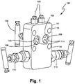
- FIG. 1 shows a self-draining head 100 according to an embodiment of the present disclosure.
- Head 100 as shown in FIG. 1 comprise in one embodiment a head body 101, drain/vent plugs 102, an equalizer valve 104, isolation valves 110, transmitter mount holes 116, transmitter process coupling ports 114, internal drain/vent drain passages 103, and impulse drain passages 106. Further elements of embodiments of the present disclosure are shown in further figures.
- two impulse passages and two impulse drain passages may be coupled between two impulse ports ( FIG. 2 ) and two transmitter process coupling ports 114.
- a single impulse passage and impulse drain passage may be coupled between a single impulse port and a single transmitter process coupling port.
- two isolation valves and an equalizer valve are shown, it should be understood that more or fewer valves (including zero) may be used, and that a different number of internal passages may be used for various other head configurations without departing from the scope of the disclosure.
- FIG. 2 is an elevation view of self-draining head 100 showing internal passages of the head 100 in body 200 using dashed lines.
- FIG. 6 is a larger view of the body 200 of head 100 also showing internal passages of the head 100 using dashed lines, but omitting the external components of head 100 for purposes of clarity.
- self-draining head further comprises ports 202 for receipt of drain/vent plugs 102, equalizer seat port 204 coupleable to equalizer valve 104, and coupled to the impulse passage via an equalizer passage 207, isolation valve ports 210 coupleable to isolation valves 110, and impulse ports 212 coupleable to impulse tubing and/or process measurement devices.
- Ports 202 are the openings to drain/vent passages 203 that lead to angled drain/vent drain passages 103.
- Passages 103 are coupled to transmitter process ports 114 and to impulse passages 208.
- Impulse ports 212 are the openings to impulse passages 208 that lead to isolation valve ports 210 and then to angled impulse drain passages 106.
- Angled impulse drain passages 106 are coupled to transmitter process ports 114.
- Impulse passages 208 and drain/vent passages 203 are also coupled, in one embodiment, in a straight line so as to allow for the combined passages 203 and 208 to facilitate easy clean out with a rod-out tool in order to allow for clearance of obstructions and the like within the passages 203 and/or 208.
- the large diameter internal geometry and impulse tubes of the head 100 facilitate easy clean out with a rod-out tool.
- the ports 202 and 212 allow a rod-out tool to pass through the entire length of the impulse and drain/vent passages 208, 203 and clean out any build up or debris.
- drain/vent drain passages 103 and/or drain/vent passages 203 may be omitted without departing from the scope of the disclosure.
- the drain/vent drain passages 103 and impulse drain passages 106 are angled with respect to the drain/vent passages 203 and impulse passages 208, respectively, at an angle of approximately 135° toward the transmitter process ports 114, to allow for the drainage described herein.
- different angles may be used for different drainage orientation ranges without departing from the scope of the disclosure.
- Isolation valve ports 210 in one embodiment are sufficiently large so as to allow process fluid to drain from the head 100, and in one embodiment comprise bonnet seats 211 which allow isolation valve inner diameters to be self-draining.
- the bonnet seats 211 in one embodiment hold full port rising plug bonnets for primary isolation, and are large enough so that inner diameter isolation valves 110 may be self-draining, in one embodiment the same diameter as the passages 103, 106, 203, and 208.
- the impulse passages 208 intercept the chamber 220 at a point within the head 100 that is at the lowest point of the chamber 220 in one embodiment, to further facilitate drainage away from a diaphragm of the pressure transmitter.
- circular diameter passages are shown in the figures, it should be understood that other shaped passages may be employed without departing from the scope of the disclosure.
- angled slots may be employed instead of angled circular diameter passages.
- grooves may be incorporated into one or more of the passages of the head embodiments to further decrease tension forces from the process fluid and to promote draining through smaller diameter passages.
- FIG. 3 illustrates a perspective view of a head 100 connected to a pressure transmitter 302 and primary element 304, illustrated as an orifice plate, but which can be another type of primary element without departing from the scope of the disclosure.
- Pressure transmitter in one embodiment is a differential pressure monitor and transmitter that connects to the head 100 at mount holes 116, and couples to the process at transmitter process ports 114.
- Primary element 304 connects to the impulse ports 212 of head 100 through process connections 306, in one embodiment impulse tubes, to couple process fluid to the head 100 and ultimately to the process transmitter 302 for measurement of process variables such as, but not limited to, differential pressures.
- the various head embodiments disclosed herein may also be applied to static pressure measurements and coupled static pressure transmitters.
- the geometry of the head 100 preferably allows for direct mount of a pressure transmitter 302 or manifold to the head 100.
- Head 100 has internal passages and design to facilitate self-draining of the pressure transmitter, head, and flow meter as described herein.
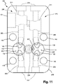
- head passages 103 and 106 are arranged and configured at angles to the transmitter differential connections and transmitter passages, and also at angles to internal passages 203 and 208, so as to allow drainage of process fluid from the system in operating orientations (see FIGS. 2 , 6 , and 11 ).
- FIG. 4 is a sectional view of the embodiment of FIG. 3 , and includes self-draining head 100 mounted to a pressure transmitter 302 and a primary element 304.
- the combination is shown in a steam on top mounting orientation in which the pressure transmitter is substantially horizontal, and the impulse tubing from the head 100 and the primary element 304 are substantially vertical.
- the angle of the impulse drain passages 106 allows fluid 400 within the transmitter 302 to flow away from the transmitter, down angled impulse drain passages 106, to drain through impulse passages 208, to the process conduit through opening 310 to primary element 304, which is positioned in use within a process flow conduit.
- the angled impulse drain passages 106 are of suitable diameter to allow accumulated fluid to overcome surface tension and capillary effects to drain away from the transmitter 302 and through the head 100 to a location where the fluid will not damage the system should it freeze, or will not damage the system due to corrosion or other properties of dangerous fluids.
- FIG. 5 shows a range of installation orientations along arrow 500 in which the head 100 may be installed and still allow drainage of process fluid away from the transmitter 302 and head 100 when process flow stops.
- FIG. 5 shows a range of installation orientations along arrow 500 in which the head 100 may be installed and still allow drainage of process fluid away from the transmitter 302 and head 100 when process flow stops.
- fluid will drain away from the transmitter diaphragm and out the head 100 due to the angles and size of the passages in the head 100.
- the head 100 with the arrangement of passages shown facilitates draining of process fluid within a 135° mounting range of operation.
- a mirrored 135° mounting range is available.
- the drain/vent plugs 102 may be removed to allow drainage of process fluid away from the transmitter 302 via drain/vent drain passages 103 and drain/vent passages 203.
- the passages 103 and 203 are angled and sized so that they act in a fashion similar to passages 106 and 208.
- the equalizer valve 104 and equalizer seat port 204 is of a standard, relatively small, diameter to allow for proper sealing of the equalizer valve. It should be noted that should process fluid be trapped within the equalizer line, this will not affect the transmitter diaphragm since all process fluid will still flow out of the diaphragm area.
- the passages 103, 106, 203, and 208 are sized at or above a diameter to allow the overcoming of surface tension when process fluid accumulates for drainage after a process flow shutdown.
- the diameter of the passages 103, 106, 203, and 208 is at least 0.375 inches, although it should be understood that other draining diameters, including those larger or smaller than 0.375 inches, may be employed without departing from the scope of the disclosure.
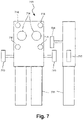
- FIG. 7 illustrates front and side elevation views of a head 700 according to another embodiment of the present disclosure.
- Head 700 incorporates isolation valves 710 and an equalizer valve 704, each with bonnets incorporated into the head 700.
- Mount 700 includes transmitter mount holes 716 and differential connections 714, and connects to a process conduit with impulse tubes 306.
- isolation valves and an equalizer valve are shown, it should be understood that more or fewer valves and internal passages may be used for various other head configurations without departing from the scope of the disclosure.
- FIG. 8 illustrates front and side elevation views of a head 800 according to another embodiment of the present disclosure.
- Head 800 incorporates an equalizer valve 804 in the head 800, and isolation valves 810 incorporated into impulse tubes 306.
- Mount 800 includes transmitter mount holes 816 and differential connections 814, and connects to a process conduit with impulse tubes 306.
- two isolation valves and an equalizer valve are shown, it should be understood that more or fewer valves and internal passages may be used for various other head configurations without departing from the scope of the disclosure.
- FIG. 9 illustrates a side elevation view of a head 900 according to another embodiment of the present disclosure.
- Head 900 uses no valves in the head body or impulse tubes 306. Instead, head 900 mounts to a manifold 902 incorporating equalizer valve 904 and isolation valves 910. The manifold is directly mountable to the head 900.
- heads 700, 800, and 900 incorporate internal passages such as those described above in head 100, and are therefore self-draining to the extent of head 100. Further, while heads 100, 700, 800, and 900 illustrate a pair of differential ports and single pressure taps, double pressure taps may be employed for redundancy without departing from the scope of the disclosure.
- Embodiments of the present disclosure may be provided with a spool section to allow more space for impulse tubes to meet ISO 5167-2 tap spacing requirements.
- Impulse tubes may be of extended length to increase heat transfer to ambient air (e.g., cooling).
- heat sink additions to the heads may be used to assist in the transfer of heat from the process fluid to ambient air.
- Heat sink geometry may be chosen to increase surface area of the head and/or impulse tubes, such as by providing fin features.
- the heads of the various embodiments may incorporate a cooling jacket in which a heat transfer fluid is pumped through the head to remove heat from the components.
Landscapes
- Physics & Mathematics (AREA)
- General Physics & Mathematics (AREA)
- Fluid Mechanics (AREA)
- Engineering & Computer Science (AREA)
- General Engineering & Computer Science (AREA)
- Mechanical Engineering (AREA)
- Chemical & Material Sciences (AREA)
- Chemical Kinetics & Catalysis (AREA)
- Measuring Fluid Pressure (AREA)
- Measuring Volume Flow (AREA)
Description
- The present disclosure relates to pressure transmitter flow meter connections. More specifically, the invention relates to a self-draining head configuration.
- Flow measurement of process fluids such as steam and caustic or dangerous fluids can cause many unique challenges, one of which is common when steam is measured in cold ambient environments. When flow of the steam stops, water trapped by surface tension in the differential pressure ports of a transmitter mount head, or near the diaphragm of the transmitter, can freeze and damage the transmitter, head, or flow meter.
- In many differential pressure flow applications it is desirable for process fluids to drain away from the transmitter and back into the process conduit when process flow is stopped. The most common scenario with this requirement is water or steam flow in cold ambient environments where shutting down flow could allow trapped water to freeze, expand, and damage sensitive meter components. It is also desirable for applications with flow of corrosive or other dangerous fluids to self-drain during a shutdown. With current designs, mounting the flow meter with the transmitter above the process conduit does not guarantee that process fluid will drain back into the pipe. The passages in the impulse tubes and ports in the current head and/or manifold have diameters that are small enough that the mass of the fluid within may not overcome the surface tension of the fluid, and thus it will remain trapped, even after process flow stops.
- A common process fluid that can cause problems in harsh environments, especially those that are subjected to cold temperatures (e.g., cold enough to freeze water), is steam. In cold temperatures, steam condenses to water, and that water can freeze in head passages, and near diaphragms of a pressure transmitter, causing a number of potential issues including damage to the process transmitter and its components, plugging of the process fluid passages, or the like.
- One proposed solution for process fluid being trapped near a transmitter diaphragm or within the head or flow meter is to increase the diameters of process fluid passages on a standard head. Another attempt at avoiding damage caused from freezing water is to create an instrument with geometry that allows water to drain away from the transmitter back into the main process line. Such a "straight drain" design does increase the amount of drainage, but water will only drain out of the impulse tubes, not the head of the meter due to small internal passages and cross-drill head geometry. In such a design, damage to the transmitter caused from freezing water has not been fully mitigated. First, traditional equalizer and isolation valves use small diameter passages in order to properly seal. Second, due to the angles of internal passageways within transmitter mount heads, process fluid will only drain if the transmitter is oriented vertically upward, even with increased diameters. Vertical installation is not feasible for many piping installations.
- Therefore, currently, the most common method used to protect a flow meter from freeze damage is heat tracing or steam tracing systems. Both of these techniques are expensive to install, operate, and maintain. For example, differential pressure flow is a desirable technology for measuring steam due to its inherent reliability, wide industry acceptance, and high temperature ranges. Approximately 45% of all energy is used to create steam and approximately 70% or more of all steam measurements use differential pressure flow technology. Many of these measurement points are in ambient environments that use heat tracing or steam tracing to prevent the condensate trapped in the primary element head from freezing and damaging the transmitters due to potentially cold ambient air temperatures. During installation, each steam trace installation for a single flow measurement installation can cost on the order or $1500 to $3000. When maintenance and operational costs are included, this cost is significantly higher.
-
WO 2016/099968 discloses a pressure transmitter coupling for coupling a pressure transmitter to a process fluid that includes a process coupling face having a process coupling port configured to couple to impulse piping. A pressure transmitter coupling face is arranged at an angle to the process coupling face, the pressure transmitter coupling face including a pressure transmitter coupling port configured to fluidically couple to the pressure transmitter. A process fluid passageway extends between the process coupling port and the pressure transmitter coupling port. A rod out port is aligned with the process fluid coupling port and configured to receive a cleaning rod therethrough to clean the process coupling port. -
US 6 272 931 discloses a full drain and vent adapter for mounting a pressure sensing transmitter or similar test instrument to a standard manifold, that is reversible for use in either gas or liquid pressure sensing applications. Combination vent or drain plugs are provided at the top and bottom of the adapter to provide drains at the bottom of the adapter and vents at the top of the adapter, regardless of liquid or gas service applications. -
WO 2013/184 554 discloses a process fluid pressure measurement system. The system includes a process fluid pressure transmitter having a pair of process fluid ports disposed coplanar with one another on a bottom surface thereof. The process fluid pressure transmitter is configured to measure a differential pressure between the pair of process fluid ports and provide an indication of the measured differential pressure over a process communication loop. A process fluid flange has a first surface configured to mount to the surface of the process fluid pressure transmitter, a second surface opposed to the first surface, and at least one lateral sidewall extending between the first and second surface. A plurality of fins are disposed proximate the lateral surface. - A self-draining transmitter mount head according to the invention is recited in claim 1.
- Another self-draining transmitter mount head according to the invention is recited in claim 13.
- A method of installing a self-draining transmitter mount head according to the invention is recited in claim 15.
- This Summary and the Abstract are provided to introduce a selection of concepts in a simplified form that are further described below in the Detailed Description.
-
-
FIG. 1 is a perspective view of a self-draining head according to an embodiment of the present disclosure. -
FIG. 2 shows the head ofFIG. 1 in elevation, with internal passages indicated by broken lines. -
FIG. 3 is a perspective view of the -draining head ofFIG. 1 with a mounted pressure variable transmitter and straight drain tubes according to another embodiment of the present disclosure. -
FIG. 4 is a sectional view of the embodiment ofFIG. 3 taken along lines 3-3 thereof. -
FIG. 5 is a view showing a range of mountings for a self-draining head according to embodiments of the present disclosure. -
FIG. 6 is a more detailed view of the head ofFIG 1 . -
FIG. 7 is a side and front elevation view of a self-draining head according to another embodiment of the present disclosure. -
FIG. 8 is a side and front elevation view of a self-draining head according to another embodiment of the present disclosure. -
FIG. 9 is a side and front elevation view of a self-draining head according to another embodiment of the present disclosure. -
FIG. 10 is a view of the head ofFIG. 4 in an inverted position. -
FIG. 11 is a more detailed view of the head ofFIG 1 in an inverted position. - Embodiments of the present disclosure provide a direct mount transmitter connection platform, referred to as the head, preferably for a differential pressure flow meter that allows water to fully drain out of the instrument by force of gravity when the transmitter is positioned above the pipe. A head which allows water to completely and automatically drain during a shutdown reduces or eliminates the need for expensive and high-maintenance heat tracing in cold environments and the potential of freeze damage when heat tracing is not present. Embodiments of the disclosure completely drain water from the transmitter and head when mounted within a specified orientation range with a transmitter mounted directly to the head. One benefit of this invention is significantly decreased total installed flow measurement costs and maintenance costs by reducing or eliminating the need to heat or steam trace measurement points.
- When process fluid that is being measured is subject to freezing, such as steam in cold ambient environments, such steam in a system including, for example, a pressure transmitter, head, and impulse tubes, may not fully drain back to the process conduit, or may not drain to a point in the system that can safely freeze without damaging the transmitter, head, or flow meter. Further, when the process fluid for which parameters are being measure is caustic, corrosive, or otherwise dangerous, it is also desirable that such fluid drain completely from the transmitter and head of a system before maintenance is performed. In many situations, it is not possible to install a process variable measurement system in an orientation that is conducive to full draining of the components of the system. Still further, if even some water remains within the pressure transmitter, head, or flow meter, damage can occur due to freezing, or if some dangerous fluid remains, damage can occur in other ways in addition to freezing. Embodiments of the present disclosure include passages to facilitate self-draining of process fluid from the pressure transmitter, head, and flow meter.
- When flow of a stream of process fluid stops in a typical head and transmitter system, water from condensed steam is often trapped in internal passages, for example by geometry, or by their orientation with respect to one or more of gravitational forces, surface tension, capillary effect, and the like. Simply enlarging the diameter of passages is not sufficient to allow for full drainage of process fluid from the system, since equalizer and isolation valves typically use small diameter passages to allow for proper sealing, and angles in passages allow drainage only if the transmitter is oriented vertically upward. Installations are not always capable of being oriented vertically, and therefore, such a system is susceptible to incomplete draining even with large diameter passages.
-
FIG. 1 shows a self-draininghead 100 according to an embodiment of the present disclosure.Head 100 as shown inFIG. 1 comprise in one embodiment ahead body 101, drain/vent plugs 102, anequalizer valve 104,isolation valves 110, transmitter mount holes 116, transmitterprocess coupling ports 114, internal drain/vent drain passages 103, and impulse drainpassages 106. Further elements of embodiments of the present disclosure are shown in further figures. For differential pressure measurement, two impulse passages and two impulse drain passages may be coupled between two impulse ports (FIG. 2 ) and two transmitterprocess coupling ports 114. For static pressure measurement, a single impulse passage and impulse drain passage may be coupled between a single impulse port and a single transmitter process coupling port. Although two isolation valves and an equalizer valve are shown, it should be understood that more or fewer valves (including zero) may be used, and that a different number of internal passages may be used for various other head configurations without departing from the scope of the disclosure. -
FIG. 2 is an elevation view of self-draininghead 100 showing internal passages of thehead 100 inbody 200 using dashed lines.FIG. 6 is a larger view of thebody 200 ofhead 100 also showing internal passages of thehead 100 using dashed lines, but omitting the external components ofhead 100 for purposes of clarity. As is shown in the embodiment ofFIGS. 2 and6 , self-draining head further comprisesports 202 for receipt of drain/vent plugs 102,equalizer seat port 204 coupleable toequalizer valve 104, and coupled to the impulse passage via anequalizer passage 207,isolation valve ports 210 coupleable toisolation valves 110, andimpulse ports 212 coupleable to impulse tubing and/or process measurement devices.Ports 202 are the openings to drain/vent passages 203 that lead to angled drain/vent drain passages 103.Passages 103 are coupled totransmitter process ports 114 and toimpulse passages 208.Impulse ports 212 are the openings toimpulse passages 208 that lead toisolation valve ports 210 and then to angledimpulse drain passages 106. Angledimpulse drain passages 106 are coupled totransmitter process ports 114. -
Impulse passages 208 and drain/vent passages 203 are also coupled, in one embodiment, in a straight line so as to allow for the combinedpassages passages 203 and/or 208. The large diameter internal geometry and impulse tubes of thehead 100 facilitate easy clean out with a rod-out tool. In this embodiment, theports vent passages passages 203, and angled drain/vent drain passages 103 are shown in the figures, the drain/vent drain passages 103 and/or drain/vent passages 203 may be omitted without departing from the scope of the disclosure. In one embodiment, the drain/vent drain passages 103 and impulse drainpassages 106 are angled with respect to the drain/vent passages 203 andimpulse passages 208, respectively, at an angle of approximately 135° toward thetransmitter process ports 114, to allow for the drainage described herein. However, it should be understood that different angles may be used for different drainage orientation ranges without departing from the scope of the disclosure. -
Isolation valve ports 210 in one embodiment are sufficiently large so as to allow process fluid to drain from thehead 100, and in one embodiment comprisebonnet seats 211 which allow isolation valve inner diameters to be self-draining. The bonnet seats 211 in one embodiment hold full port rising plug bonnets for primary isolation, and are large enough so that innerdiameter isolation valves 110 may be self-draining, in one embodiment the same diameter as thepassages - Adjacent the
differential connections 114, thepassages diaphragm clearance chamber 220. At thischamber 220, theimpulse passages 208 intercept thechamber 220 at a point within thehead 100 that is at the lowest point of thechamber 220 in one embodiment, to further facilitate drainage away from a diaphragm of the pressure transmitter. - While circular diameter passages are shown in the figures, it should be understood that other shaped passages may be employed without departing from the scope of the disclosure. For example, angled slots may be employed instead of angled circular diameter passages. Still further, grooves may be incorporated into one or more of the passages of the head embodiments to further decrease tension forces from the process fluid and to promote draining through smaller diameter passages.
-
FIG. 3 illustrates a perspective view of ahead 100 connected to apressure transmitter 302 andprimary element 304, illustrated as an orifice plate, but which can be another type of primary element without departing from the scope of the disclosure. Pressure transmitter in one embodiment is a differential pressure monitor and transmitter that connects to thehead 100 at mount holes 116, and couples to the process attransmitter process ports 114.Primary element 304 connects to theimpulse ports 212 ofhead 100 throughprocess connections 306, in one embodiment impulse tubes, to couple process fluid to thehead 100 and ultimately to theprocess transmitter 302 for measurement of process variables such as, but not limited to, differential pressures. The various head embodiments disclosed herein may also be applied to static pressure measurements and coupled static pressure transmitters. As is also shown inFIG. 3 , the geometry of thehead 100 preferably allows for direct mount of apressure transmitter 302 or manifold to thehead 100. -
Head 100 has internal passages and design to facilitate self-draining of the pressure transmitter, head, and flow meter as described herein. Specifically, in one embodiment,head passages internal passages FIGS. 2 ,6 , and11 ). -
FIG. 4 is a sectional view of the embodiment ofFIG. 3 , and includes self-draininghead 100 mounted to apressure transmitter 302 and aprimary element 304. The combination is shown in a steam on top mounting orientation in which the pressure transmitter is substantially horizontal, and the impulse tubing from thehead 100 and theprimary element 304 are substantially vertical. The angle of theimpulse drain passages 106 allows fluid 400 within thetransmitter 302 to flow away from the transmitter, down angledimpulse drain passages 106, to drain throughimpulse passages 208, to the process conduit throughopening 310 toprimary element 304, which is positioned in use within a process flow conduit. The angledimpulse drain passages 106 are of suitable diameter to allow accumulated fluid to overcome surface tension and capillary effects to drain away from thetransmitter 302 and through thehead 100 to a location where the fluid will not damage the system should it freeze, or will not damage the system due to corrosion or other properties of dangerous fluids. - The angled nature of the
impulse drain passages 106 with respect to thetransmitter 302 and theimpulse passages 208 allows for installation of thehead 100 within a wide range of angular steam on top orientations, as shown inFIG. 5. FIG. 5 shows a range of installation orientations alongarrow 500 in which thehead 100 may be installed and still allow drainage of process fluid away from thetransmitter 302 andhead 100 when process flow stops. In the orientations from the left orientation ofFIG. 5 to the right orientation ofFIG. 5 , alongarrow 500, fluid will drain away from the transmitter diaphragm and out thehead 100 due to the angles and size of the passages in thehead 100. Thehead 100 with the arrangement of passages shown facilitates draining of process fluid within a 135° mounting range of operation. - Further, if the
head 100 were welded to the impulse tubes in the opposite direction, e.g., beneath a process conduit, as shown inFIGS. 10-11 , a mirrored 135° mounting range is available. With this installation orientation, the drain/vent plugs 102 may be removed to allow drainage of process fluid away from thetransmitter 302 via drain/vent drain passages 103 and drain/vent passages 203. In such a range of mounting orientation, thepassages passages - In one embodiment, the
equalizer valve 104 andequalizer seat port 204 is of a standard, relatively small, diameter to allow for proper sealing of the equalizer valve. It should be noted that should process fluid be trapped within the equalizer line, this will not affect the transmitter diaphragm since all process fluid will still flow out of the diaphragm area. - In one embodiment, the
passages passages - Alternative embodiments of the present disclosure are shown in
FIGS. 7-9 .FIG. 7 illustrates front and side elevation views of ahead 700 according to another embodiment of the present disclosure.Head 700 incorporatesisolation valves 710 and anequalizer valve 704, each with bonnets incorporated into thehead 700.Mount 700 includes transmitter mount holes 716 anddifferential connections 714, and connects to a process conduit withimpulse tubes 306. Although two isolation valves and an equalizer valve are shown, it should be understood that more or fewer valves and internal passages may be used for various other head configurations without departing from the scope of the disclosure. -
FIG. 8 illustrates front and side elevation views of ahead 800 according to another embodiment of the present disclosure.Head 800 incorporates anequalizer valve 804 in thehead 800, andisolation valves 810 incorporated intoimpulse tubes 306.Mount 800 includes transmitter mount holes 816 anddifferential connections 814, and connects to a process conduit withimpulse tubes 306. Although two isolation valves and an equalizer valve are shown, it should be understood that more or fewer valves and internal passages may be used for various other head configurations without departing from the scope of the disclosure. -
FIG. 9 illustrates a side elevation view of ahead 900 according to another embodiment of the present disclosure.Head 900 uses no valves in the head body orimpulse tubes 306. Instead,head 900 mounts to a manifold 902 incorporatingequalizer valve 904 andisolation valves 910. The manifold is directly mountable to thehead 900. - Each of the
heads head 100, and are therefore self-draining to the extent ofhead 100. Further, whileheads - Embodiments of the present disclosure may be provided with a spool section to allow more space for impulse tubes to meet ISO 5167-2 tap spacing requirements. Impulse tubes may be of extended length to increase heat transfer to ambient air (e.g., cooling).
- Further, because the embodiments of the present disclosure may frequently be employed in steam applications, optional heat sink additions to the heads may be used to assist in the transfer of heat from the process fluid to ambient air. Heat sink geometry may be chosen to increase surface area of the head and/or impulse tubes, such as by providing fin features. In embodiments with extremely hot process temperature, the heads of the various embodiments may incorporate a cooling jacket in which a heat transfer fluid is pumped through the head to remove heat from the components.
Claims (15)
- A self-draining transmitter mount head (100, 700, 800, 900), comprising:a head body (101);a transmitter process coupling port (114) in the head body (101);an impulse port (212) in the head body (101);an impulse passage (208) coupled to the impulse port (212); andan impulse drain passage (106) coupled between the transmitter process coupling port (114) and the impulse passage (208), the impulse drain passage (106) positioned at an angle to the impulse passage (208), said angled impulse drain passage (106) capable to drain away a fluid from the transmitter process coupling port (114) through a range of head installation angles;a drain/vent port (202) in the head body (101);a removable drain/vent plug (102) configured to seal the drain/vent port;a drain/vent passage (203) coupled between the drain/vent port and the impulse passage (208), said impulse passage (208) and said drain/vent passage (203) coupled in a straight line; anda drain/vent drain passage (103) coupled between the transmitter process coupling port (114) and the impulse passage (208) and positioned at an angle to the impulse passage (208).
- The self-draining head (100, 700, 800, 900) of claim 1, further comprising:an equalizer seat port (204) in the head body (101), the equalizer seat port (204) coupled to an equalizer passage (207) coupled to the impulse passage (208); andan equalizer valve (104) coupled to the equalizer port (204).
- The self-draining head (100, 700, 800, 900) of claim 1, further comprising:an isolation valve port (210) in the head body (101), the isolation valve port (210) coupled to the impulse passage (208); andan isolation valve (110) coupled to the isolation valve port (210).
- The self-draining head (100, 700, 800, 900) of claim 3,wherein the isolation valve (110) is a self-draining valve, andwherein the head (100, 700, 800, 900) further comprises a bonnet seat (211) in which the isolation valve (110) is seated for self-draining, the bonnet seat (211) comprising a full port rising plug bonnet.
- The self-draining head (100, 700, 800, 900) of claim 1, wherein:the transmitter process coupling port (114) comprises first and second differential ports,the impulse passage (208) comprises a pair of impulse passages,the impulse drain passage (106) comprises first and second impulse drain passages,the impulse port (212) comprises first and second impulse ports,wherein the first differential port is coupled to the first impulse port by the first impulse passage (208) and the first impulse drain passage, and the second differential port is coupled to the second impulse port by the second impulse drain passage (106) and the second impulse passage; andthe head (100, 700, 800, 900) is configured for differential pressure measurement.
- The self-draining head (100, 700, 800, 900) of claim 1,
wherein said drain/vent drain passage (103) is capable to drain away a fluid from the transmitter process coupling port (114) through a second range of head installation angles 180 degrees opposite to the head installation angle. - The self-draining head (100, 700, 800, 900) of claim 1,wherein the range of installation angles is approximately 135 degrees, orwherein each of the impulse passage (208) and the impulse drain passage (106) have a diameter of at least 0.375 inches.
- The self-draining head (100, 700, 800, 900) of claim 1, further comprisinga cooling element for the head (100, 700, 800, 900),wherein the cooling element comprises at least one heat sink fin coupled to the head body (101), orwherein the cooling element comprises at least one cooling passage through the head body (101), the at least one cooling passage coupleable to a heat transfer fluid to remove heat from the head body (101).
- The self-draining head (100, 700, 800, 900) of claim 1, wherein at least one of the impulse passage (208) and the impulse drain passage (106) include at least one groove positioned along a longitudinal length thereof.
- The self-draining head (100, 700, 800, 900) of claim 1, wherein the impulse passage (208) and the impulse drain passage (106) are coupled to a chamber (220), the chamber (220) adjacent the transmitter process coupling port, and the impulse passage (208) couples to the chamber (220) at a lowest point in the chamber (220) when the head (100, 700, 800, 900) is installed in a head installation angle within the range of head installation angles.
- The self-draining head (100, 700, 800, 900) of claim 1, wherein the impulse passage (208) and impulse drain passage (106) are of sufficient diameter to overcome surface tension of a mass of water in the passages under gravitational force at a head installation angle within the range of head installation angles.
- The self-draining head (100, 700, 800, 900) of claim 1,wherein the head (100, 700, 800, 900) is configured to be mounted directly to a pressure transmitter (302), orwherein the head (100, 700, 800, 900) is integrally formed with impulse lines and a primary element.
- A self-draining transmitter mount head (100, 700, 800, 900), comprising:a head body (101);a pair of differential transmitter process coupling ports (114) in the head body (101);a pair of impulse ports (212) in the head body (101);a pair of impulse passages (208), wherein a first of the impulse passages is coupled to a first of the impulse ports (212), and a second of the impulse passages is coupled to a second of the impulse ports (212); anda pair of impulse drain passages (106), wherein a first impulse drain passage is coupled at an angle between the first differential transmitter process coupling port (114) and the first impulse passage, and a second impulse drain passage is coupled at an angle between the second differential transmitter process coupling port (114) and the second impulse passage;wherein the angled impulse drain passages (106) are configured to drain away from the differential transmitter process coupling ports (114) through a range of head installation angles;a pair of drain/vent ports in the head body (101);a removable drain/vent plug (102) configured to seal each drain/vent port;a pair of drain/vent passages (203), a first drain/vent passage coupled between a first of the respective drain/vent ports and the first impulse passage, and a second drain/vent passage coupled between a second of the respective drain/vent ports and the second impulse passage; wherein each drain/vent passage (203) is aligned with its respective impulse passage (208);a first drain/vent drain passage (103) between the first drain/vent passage (203) and the first differential transmitter process coupling port (114), the first drain/vent drain passage (103) positioned at an angle to the first impulse passage (208); anda second drain/vent drain passage (103) between the second drain/vent passage (203) and the second differential transmitter process coupling port (114), the second drain/vent drain passage (103) positioned at an angle to the second impulse passage (208).
- The self-draining head (100, 700, 800, 900) of claim 13,
wherein each drain/vent drain passage is angled relative to a second head installation angle that positions the drain/vent drain passage to drain away from the transmitter coupling port through a second range of head installation angles 180 degrees opposite the head installation angle. - A method of installing a self-draining transmitter mount head (100, 700, 800, 900) according to any of the preceding claims, comprising:mounting the head (100, 700, 800, 900) in an orientation to allow internal draining of process fluid within the head away from a transmitter process coupling port (114) when process flow stops;wherein mounting the head (100, 700, 800, 900) further comprisesmounting said head (100, 700, 800, 900) within a range of orientations to position drain passages of the head (100, 700, 800, 900) at such an angle in the head (100, 700, 800, 900) to drain process fluid out of the head (100, 700, 800, 900).
Applications Claiming Priority (2)
| Application Number | Priority Date | Filing Date | Title |
|---|---|---|---|
| US15/608,007 US10480981B2 (en) | 2017-05-30 | 2017-05-30 | Self-draining mount head for transmitter |
| PCT/US2018/032066 WO2018222368A1 (en) | 2017-05-30 | 2018-05-10 | Self-draining mount head for transmitter |
Publications (2)
| Publication Number | Publication Date |
|---|---|
| EP3615905A1 EP3615905A1 (en) | 2020-03-04 |
| EP3615905B1 true EP3615905B1 (en) | 2022-08-17 |
Family
ID=62685086
Family Applications (1)
| Application Number | Title | Priority Date | Filing Date |
|---|---|---|---|
| EP18732971.9A Active EP3615905B1 (en) | 2017-05-30 | 2018-05-10 | Self-draining mount head for pressure transmitter |
Country Status (5)
| Country | Link |
|---|---|
| US (1) | US10480981B2 (en) |
| EP (1) | EP3615905B1 (en) |
| JP (1) | JP7025061B2 (en) |
| CN (2) | CN207600542U (en) |
| WO (1) | WO2018222368A1 (en) |
Families Citing this family (5)
| Publication number | Priority date | Publication date | Assignee | Title |
|---|---|---|---|---|
| US10480981B2 (en) * | 2017-05-30 | 2019-11-19 | Dieterich Standard, Inc. | Self-draining mount head for transmitter |
| GB2578780B (en) | 2018-11-09 | 2021-10-27 | Spirax Sarco Ltd | A differential pressure metering apparatus |
| USD912370S1 (en) | 2019-09-06 | 2021-03-09 | Shun On John Ngan | Hooded garment |
| DE102021126559A1 (en) | 2021-10-13 | 2023-04-13 | Volkswagen Aktiengesellschaft | Device for measuring a pressure difference |
| CN115950494A (en) * | 2023-02-09 | 2023-04-11 | 上海科洋科技股份有限公司 | Integral wafer flowmeter body and flowmeter |
Family Cites Families (14)
| Publication number | Priority date | Publication date | Assignee | Title |
|---|---|---|---|---|
| JPH0643057A (en) * | 1991-04-26 | 1994-02-18 | Yokogawa Electric Corp | Overpressure protection mechanism for differential pressure transmitter |
| US5832956A (en) * | 1995-09-25 | 1998-11-10 | Pgi International Ltd. | Three valve controlled vent manifold |
| TW354371B (en) * | 1997-01-09 | 1999-03-11 | Peter B Hutton | A module valve manifold, a valve module and an integral valve manifold/differential pressure transducer/differential pressure transmitter |
| US5988203A (en) * | 1997-10-01 | 1999-11-23 | Hutton; Peter B. | Two-piece manifold |
| US5823228A (en) * | 1997-02-05 | 1998-10-20 | Keystone International Holdings Corp. | Valve manifold |
| US6272931B1 (en) | 1998-09-14 | 2001-08-14 | Pgi International, Ltd. | Full drain and vent adapter for pressure sensing transmitter |
| US6537339B2 (en) * | 2001-05-04 | 2003-03-25 | Nelson Industries, Inc. | Moisture draining inside-out reverse flow air filter, mold and method |
| CN101852632B (en) * | 2010-06-22 | 2012-07-04 | 李岩峰 | High temperature diaphragm assembly |
| CN202013217U (en) * | 2011-02-28 | 2011-10-19 | 江苏理文造纸有限公司 | Installation mechanism of a differential pressure transmitter |
| US9228866B2 (en) * | 2012-06-06 | 2016-01-05 | Dieterich Standard, Inc. | Process fluid flow transmitter with finned coplanar process fluid flange |
| US10081039B2 (en) * | 2014-12-18 | 2018-09-25 | Dieterich Standard, Inc. | Rodable pressure coupling |
| EP3112818B1 (en) * | 2015-07-01 | 2020-02-26 | imtmedical ag | Respiratory flow sensor |
| CN206113980U (en) * | 2016-08-31 | 2017-04-19 | 重庆四联测控技术有限公司 | Mounting panel based on changer |
| US10480981B2 (en) * | 2017-05-30 | 2019-11-19 | Dieterich Standard, Inc. | Self-draining mount head for transmitter |
-
2017
- 2017-05-30 US US15/608,007 patent/US10480981B2/en active Active
- 2017-09-30 CN CN201721291244.5U patent/CN207600542U/en not_active Expired - Fee Related
- 2017-09-30 CN CN201710919004.3A patent/CN108981840B/en active Active
-
2018
- 2018-05-10 JP JP2020517281A patent/JP7025061B2/en not_active Expired - Fee Related
- 2018-05-10 WO PCT/US2018/032066 patent/WO2018222368A1/en not_active Ceased
- 2018-05-10 EP EP18732971.9A patent/EP3615905B1/en active Active
Also Published As
| Publication number | Publication date |
|---|---|
| CN108981840B (en) | 2021-03-30 |
| WO2018222368A1 (en) | 2018-12-06 |
| JP2020521988A (en) | 2020-07-27 |
| EP3615905A1 (en) | 2020-03-04 |
| JP7025061B2 (en) | 2022-02-24 |
| WO2018222368A8 (en) | 2019-01-10 |
| CN207600542U (en) | 2018-07-10 |
| US10480981B2 (en) | 2019-11-19 |
| CN108981840A (en) | 2018-12-11 |
| US20180345168A1 (en) | 2018-12-06 |
Similar Documents
| Publication | Publication Date | Title |
|---|---|---|
| US10480981B2 (en) | Self-draining mount head for transmitter | |
| EP2859316B1 (en) | Process fluid flow transmitter with finned coplanar process fluid flange | |
| JP6035436B2 (en) | Steam trap monitoring system, piping assembly device, and steam trap unit | |
| CA2971388C (en) | A pressure transmitter coupling | |
| CN103791664B (en) | A kind of with the heating power expansion valve being unidirectionally controlled function | |
| CN1105293C (en) | System for measuring differential pressure, flow, and level | |
| BR112013016357B1 (en) | heat exchanger assembly, and use of a pressure pulse damping device | |
| CN103791663B (en) | A kind of with the heating power expansion valve being unidirectionally controlled function | |
| US10317003B2 (en) | Double block and bleed system for an orifice fitting | |
| US20200096422A1 (en) | Systems And Methods For Accessing And Monitoring A Fluid Within A Pressurized Pipe | |
| CN105840909B (en) | Manifold for the process variable transmitter with steam connector | |
| CN206725032U (en) | For reducing the device and tower of the corrosion of liquid level gauge gas phase flange diaphragm | |
| CN216899047U (en) | Integrated heat exchange device of differential pressure type flowmeter | |
| CN219101434U (en) | Oil temperature adjusting assembly and oil adjusting and controlling system | |
| EP3877729B1 (en) | A differential pressure metering apparatus | |
| CN115950494A (en) | Integral wafer flowmeter body and flowmeter | |
| KR20170001042A (en) | Apparatus for steam tracing and method for manufacturing the same | |
| JP3432648B2 (en) | Flange adapter | |
| CN115031901A (en) | Liquid leakage detection system and semiconductor process equipment | |
| CN118242157A (en) | Oil temperature regulating components and oil regulating and control systems | |
| JP2008267962A (en) | Flow meter and connecting tube unit for the same |
Legal Events
| Date | Code | Title | Description |
|---|---|---|---|
| STAA | Information on the status of an ep patent application or granted ep patent |
Free format text: STATUS: UNKNOWN |
|
| STAA | Information on the status of an ep patent application or granted ep patent |
Free format text: STATUS: THE INTERNATIONAL PUBLICATION HAS BEEN MADE |
|
| PUAI | Public reference made under article 153(3) epc to a published international application that has entered the european phase |
Free format text: ORIGINAL CODE: 0009012 |
|
| STAA | Information on the status of an ep patent application or granted ep patent |
Free format text: STATUS: REQUEST FOR EXAMINATION WAS MADE |
|
| 17P | Request for examination filed |
Effective date: 20191127 |
|
| AK | Designated contracting states |
Kind code of ref document: A1 Designated state(s): AL AT BE BG CH CY CZ DE DK EE ES FI FR GB GR HR HU IE IS IT LI LT LU LV MC MK MT NL NO PL PT RO RS SE SI SK SM TR |
|
| AX | Request for extension of the european patent |
Extension state: BA ME |
|
| DAV | Request for validation of the european patent (deleted) | ||
| DAX | Request for extension of the european patent (deleted) | ||
| STAA | Information on the status of an ep patent application or granted ep patent |
Free format text: STATUS: EXAMINATION IS IN PROGRESS |
|
| 17Q | First examination report despatched |
Effective date: 20201127 |
|
| GRAP | Despatch of communication of intention to grant a patent |
Free format text: ORIGINAL CODE: EPIDOSNIGR1 |
|
| STAA | Information on the status of an ep patent application or granted ep patent |
Free format text: STATUS: GRANT OF PATENT IS INTENDED |
|
| INTG | Intention to grant announced |
Effective date: 20211112 |
|
| RIN1 | Information on inventor provided before grant (corrected) |
Inventor name: STROM, GREGORY, ROBERT Inventor name: STEFFL, CHAD, ANDREW Inventor name: BINGHAM, BRYCE, ARTHUR Inventor name: STEHLE, JOHN, HENRY Inventor name: KENYON, NATHANIEL, KIRK |
|
| GRAJ | Information related to disapproval of communication of intention to grant by the applicant or resumption of examination proceedings by the epo deleted |
Free format text: ORIGINAL CODE: EPIDOSDIGR1 |
|
| STAA | Information on the status of an ep patent application or granted ep patent |
Free format text: STATUS: EXAMINATION IS IN PROGRESS |
|
| GRAP | Despatch of communication of intention to grant a patent |
Free format text: ORIGINAL CODE: EPIDOSNIGR1 |
|
| STAA | Information on the status of an ep patent application or granted ep patent |
Free format text: STATUS: GRANT OF PATENT IS INTENDED |
|
| INTC | Intention to grant announced (deleted) | ||
| INTG | Intention to grant announced |
Effective date: 20220309 |
|
| GRAS | Grant fee paid |
Free format text: ORIGINAL CODE: EPIDOSNIGR3 |
|
| GRAA | (expected) grant |
Free format text: ORIGINAL CODE: 0009210 |
|
| STAA | Information on the status of an ep patent application or granted ep patent |
Free format text: STATUS: THE PATENT HAS BEEN GRANTED |
|
| AK | Designated contracting states |
Kind code of ref document: B1 Designated state(s): AL AT BE BG CH CY CZ DE DK EE ES FI FR GB GR HR HU IE IS IT LI LT LU LV MC MK MT NL NO PL PT RO RS SE SI SK SM TR |
|
| REG | Reference to a national code |
Ref country code: CH Ref legal event code: EP |
|
| REG | Reference to a national code |
Ref country code: DE Ref legal event code: R096 Ref document number: 602018039404 Country of ref document: DE |
|
| REG | Reference to a national code |
Ref country code: IE Ref legal event code: FG4D |
|
| REG | Reference to a national code |
Ref country code: AT Ref legal event code: REF Ref document number: 1512468 Country of ref document: AT Kind code of ref document: T Effective date: 20220915 |
|
| REG | Reference to a national code |
Ref country code: NL Ref legal event code: MP Effective date: 20220817 |
|
| REG | Reference to a national code |
Ref country code: LT Ref legal event code: MG9D |
|
| PG25 | Lapsed in a contracting state [announced via postgrant information from national office to epo] |
Ref country code: SE Free format text: LAPSE BECAUSE OF FAILURE TO SUBMIT A TRANSLATION OF THE DESCRIPTION OR TO PAY THE FEE WITHIN THE PRESCRIBED TIME-LIMIT Effective date: 20220817 Ref country code: RS Free format text: LAPSE BECAUSE OF FAILURE TO SUBMIT A TRANSLATION OF THE DESCRIPTION OR TO PAY THE FEE WITHIN THE PRESCRIBED TIME-LIMIT Effective date: 20220817 Ref country code: PT Free format text: LAPSE BECAUSE OF FAILURE TO SUBMIT A TRANSLATION OF THE DESCRIPTION OR TO PAY THE FEE WITHIN THE PRESCRIBED TIME-LIMIT Effective date: 20221219 Ref country code: NO Free format text: LAPSE BECAUSE OF FAILURE TO SUBMIT A TRANSLATION OF THE DESCRIPTION OR TO PAY THE FEE WITHIN THE PRESCRIBED TIME-LIMIT Effective date: 20221117 Ref country code: NL Free format text: LAPSE BECAUSE OF FAILURE TO SUBMIT A TRANSLATION OF THE DESCRIPTION OR TO PAY THE FEE WITHIN THE PRESCRIBED TIME-LIMIT Effective date: 20220817 Ref country code: LV Free format text: LAPSE BECAUSE OF FAILURE TO SUBMIT A TRANSLATION OF THE DESCRIPTION OR TO PAY THE FEE WITHIN THE PRESCRIBED TIME-LIMIT Effective date: 20220817 Ref country code: LT Free format text: LAPSE BECAUSE OF FAILURE TO SUBMIT A TRANSLATION OF THE DESCRIPTION OR TO PAY THE FEE WITHIN THE PRESCRIBED TIME-LIMIT Effective date: 20220817 Ref country code: FI Free format text: LAPSE BECAUSE OF FAILURE TO SUBMIT A TRANSLATION OF THE DESCRIPTION OR TO PAY THE FEE WITHIN THE PRESCRIBED TIME-LIMIT Effective date: 20220817 |
|
| REG | Reference to a national code |
Ref country code: AT Ref legal event code: MK05 Ref document number: 1512468 Country of ref document: AT Kind code of ref document: T Effective date: 20220817 |
|
| PG25 | Lapsed in a contracting state [announced via postgrant information from national office to epo] |
Ref country code: PL Free format text: LAPSE BECAUSE OF FAILURE TO SUBMIT A TRANSLATION OF THE DESCRIPTION OR TO PAY THE FEE WITHIN THE PRESCRIBED TIME-LIMIT Effective date: 20220817 Ref country code: IS Free format text: LAPSE BECAUSE OF FAILURE TO SUBMIT A TRANSLATION OF THE DESCRIPTION OR TO PAY THE FEE WITHIN THE PRESCRIBED TIME-LIMIT Effective date: 20221217 Ref country code: HR Free format text: LAPSE BECAUSE OF FAILURE TO SUBMIT A TRANSLATION OF THE DESCRIPTION OR TO PAY THE FEE WITHIN THE PRESCRIBED TIME-LIMIT Effective date: 20220817 Ref country code: GR Free format text: LAPSE BECAUSE OF FAILURE TO SUBMIT A TRANSLATION OF THE DESCRIPTION OR TO PAY THE FEE WITHIN THE PRESCRIBED TIME-LIMIT Effective date: 20221118 |
|
| PG25 | Lapsed in a contracting state [announced via postgrant information from national office to epo] |
Ref country code: SM Free format text: LAPSE BECAUSE OF FAILURE TO SUBMIT A TRANSLATION OF THE DESCRIPTION OR TO PAY THE FEE WITHIN THE PRESCRIBED TIME-LIMIT Effective date: 20220817 Ref country code: RO Free format text: LAPSE BECAUSE OF FAILURE TO SUBMIT A TRANSLATION OF THE DESCRIPTION OR TO PAY THE FEE WITHIN THE PRESCRIBED TIME-LIMIT Effective date: 20220817 Ref country code: ES Free format text: LAPSE BECAUSE OF FAILURE TO SUBMIT A TRANSLATION OF THE DESCRIPTION OR TO PAY THE FEE WITHIN THE PRESCRIBED TIME-LIMIT Effective date: 20220817 Ref country code: DK Free format text: LAPSE BECAUSE OF FAILURE TO SUBMIT A TRANSLATION OF THE DESCRIPTION OR TO PAY THE FEE WITHIN THE PRESCRIBED TIME-LIMIT Effective date: 20220817 Ref country code: CZ Free format text: LAPSE BECAUSE OF FAILURE TO SUBMIT A TRANSLATION OF THE DESCRIPTION OR TO PAY THE FEE WITHIN THE PRESCRIBED TIME-LIMIT Effective date: 20220817 Ref country code: AT Free format text: LAPSE BECAUSE OF FAILURE TO SUBMIT A TRANSLATION OF THE DESCRIPTION OR TO PAY THE FEE WITHIN THE PRESCRIBED TIME-LIMIT Effective date: 20220817 |
|
| REG | Reference to a national code |
Ref country code: DE Ref legal event code: R097 Ref document number: 602018039404 Country of ref document: DE |
|
| PG25 | Lapsed in a contracting state [announced via postgrant information from national office to epo] |
Ref country code: SK Free format text: LAPSE BECAUSE OF FAILURE TO SUBMIT A TRANSLATION OF THE DESCRIPTION OR TO PAY THE FEE WITHIN THE PRESCRIBED TIME-LIMIT Effective date: 20220817 Ref country code: EE Free format text: LAPSE BECAUSE OF FAILURE TO SUBMIT A TRANSLATION OF THE DESCRIPTION OR TO PAY THE FEE WITHIN THE PRESCRIBED TIME-LIMIT Effective date: 20220817 |
|
| PLBE | No opposition filed within time limit |
Free format text: ORIGINAL CODE: 0009261 |
|
| STAA | Information on the status of an ep patent application or granted ep patent |
Free format text: STATUS: NO OPPOSITION FILED WITHIN TIME LIMIT |
|
| PG25 | Lapsed in a contracting state [announced via postgrant information from national office to epo] |
Ref country code: AL Free format text: LAPSE BECAUSE OF FAILURE TO SUBMIT A TRANSLATION OF THE DESCRIPTION OR TO PAY THE FEE WITHIN THE PRESCRIBED TIME-LIMIT Effective date: 20220817 |
|
| 26N | No opposition filed |
Effective date: 20230519 |
|
| PGFP | Annual fee paid to national office [announced via postgrant information from national office to epo] |
Ref country code: CH Payment date: 20230602 Year of fee payment: 6 |
|
| PG25 | Lapsed in a contracting state [announced via postgrant information from national office to epo] |
Ref country code: SI Free format text: LAPSE BECAUSE OF FAILURE TO SUBMIT A TRANSLATION OF THE DESCRIPTION OR TO PAY THE FEE WITHIN THE PRESCRIBED TIME-LIMIT Effective date: 20220817 |
|
| PG25 | Lapsed in a contracting state [announced via postgrant information from national office to epo] |
Ref country code: MC Free format text: LAPSE BECAUSE OF FAILURE TO SUBMIT A TRANSLATION OF THE DESCRIPTION OR TO PAY THE FEE WITHIN THE PRESCRIBED TIME-LIMIT Effective date: 20220817 |
|
| GBPC | Gb: european patent ceased through non-payment of renewal fee |
Effective date: 20230510 |
|
| REG | Reference to a national code |
Ref country code: BE Ref legal event code: MM Effective date: 20230531 |
|
| PG25 | Lapsed in a contracting state [announced via postgrant information from national office to epo] |
Ref country code: MC Free format text: LAPSE BECAUSE OF FAILURE TO SUBMIT A TRANSLATION OF THE DESCRIPTION OR TO PAY THE FEE WITHIN THE PRESCRIBED TIME-LIMIT Effective date: 20220817 Ref country code: LU Free format text: LAPSE BECAUSE OF NON-PAYMENT OF DUE FEES Effective date: 20230510 |
|
| REG | Reference to a national code |
Ref country code: IE Ref legal event code: MM4A |
|
| PG25 | Lapsed in a contracting state [announced via postgrant information from national office to epo] |
Ref country code: IE Free format text: LAPSE BECAUSE OF NON-PAYMENT OF DUE FEES Effective date: 20230510 |
|
| PG25 | Lapsed in a contracting state [announced via postgrant information from national office to epo] |
Ref country code: IE Free format text: LAPSE BECAUSE OF NON-PAYMENT OF DUE FEES Effective date: 20230510 Ref country code: GB Free format text: LAPSE BECAUSE OF NON-PAYMENT OF DUE FEES Effective date: 20230510 |
|
| PG25 | Lapsed in a contracting state [announced via postgrant information from national office to epo] |
Ref country code: IT Free format text: LAPSE BECAUSE OF FAILURE TO SUBMIT A TRANSLATION OF THE DESCRIPTION OR TO PAY THE FEE WITHIN THE PRESCRIBED TIME-LIMIT Effective date: 20220817 Ref country code: FR Free format text: LAPSE BECAUSE OF NON-PAYMENT OF DUE FEES Effective date: 20230531 Ref country code: BE Free format text: LAPSE BECAUSE OF NON-PAYMENT OF DUE FEES Effective date: 20230531 |
|
| PG25 | Lapsed in a contracting state [announced via postgrant information from national office to epo] |
Ref country code: BG Free format text: LAPSE BECAUSE OF FAILURE TO SUBMIT A TRANSLATION OF THE DESCRIPTION OR TO PAY THE FEE WITHIN THE PRESCRIBED TIME-LIMIT Effective date: 20220817 |
|
| PG25 | Lapsed in a contracting state [announced via postgrant information from national office to epo] |
Ref country code: BG Free format text: LAPSE BECAUSE OF FAILURE TO SUBMIT A TRANSLATION OF THE DESCRIPTION OR TO PAY THE FEE WITHIN THE PRESCRIBED TIME-LIMIT Effective date: 20220817 |
|
| REG | Reference to a national code |
Ref country code: CH Ref legal event code: PL |
|
| PG25 | Lapsed in a contracting state [announced via postgrant information from national office to epo] |
Ref country code: CH Free format text: LAPSE BECAUSE OF NON-PAYMENT OF DUE FEES Effective date: 20240531 |
|
| PGFP | Annual fee paid to national office [announced via postgrant information from national office to epo] |
Ref country code: DE Payment date: 20250423 Year of fee payment: 8 |
|
| PG25 | Lapsed in a contracting state [announced via postgrant information from national office to epo] |
Ref country code: CY Free format text: LAPSE BECAUSE OF FAILURE TO SUBMIT A TRANSLATION OF THE DESCRIPTION OR TO PAY THE FEE WITHIN THE PRESCRIBED TIME-LIMIT; INVALID AB INITIO Effective date: 20180510 |
|
| PG25 | Lapsed in a contracting state [announced via postgrant information from national office to epo] |
Ref country code: HU Free format text: LAPSE BECAUSE OF FAILURE TO SUBMIT A TRANSLATION OF THE DESCRIPTION OR TO PAY THE FEE WITHIN THE PRESCRIBED TIME-LIMIT; INVALID AB INITIO Effective date: 20180510 |
|
| PG25 | Lapsed in a contracting state [announced via postgrant information from national office to epo] |
Ref country code: TR Free format text: LAPSE BECAUSE OF FAILURE TO SUBMIT A TRANSLATION OF THE DESCRIPTION OR TO PAY THE FEE WITHIN THE PRESCRIBED TIME-LIMIT Effective date: 20220817 |