EP3615795B1 - System and method for removing or installing a main shaft of a wind turbine with rigging - Google Patents
System and method for removing or installing a main shaft of a wind turbine with rigging Download PDFInfo
- Publication number
- EP3615795B1 EP3615795B1 EP18791675.4A EP18791675A EP3615795B1 EP 3615795 B1 EP3615795 B1 EP 3615795B1 EP 18791675 A EP18791675 A EP 18791675A EP 3615795 B1 EP3615795 B1 EP 3615795B1
- Authority
- EP
- European Patent Office
- Prior art keywords
- main shaft
- bedplate
- downwind
- rigging
- downwind end
- Prior art date
- Legal status (The legal status is an assumption and is not a legal conclusion. Google has not performed a legal analysis and makes no representation as to the accuracy of the status listed.)
- Active
Links
Images



Classifications
-
- F—MECHANICAL ENGINEERING; LIGHTING; HEATING; WEAPONS; BLASTING
- F03—MACHINES OR ENGINES FOR LIQUIDS; WIND, SPRING, OR WEIGHT MOTORS; PRODUCING MECHANICAL POWER OR A REACTIVE PROPULSIVE THRUST, NOT OTHERWISE PROVIDED FOR
- F03D—WIND MOTORS
- F03D80/00—Details, components or accessories not provided for in groups F03D1/00 - F03D17/00
- F03D80/70—Bearing or lubricating arrangements
-
- F—MECHANICAL ENGINEERING; LIGHTING; HEATING; WEAPONS; BLASTING
- F03—MACHINES OR ENGINES FOR LIQUIDS; WIND, SPRING, OR WEIGHT MOTORS; PRODUCING MECHANICAL POWER OR A REACTIVE PROPULSIVE THRUST, NOT OTHERWISE PROVIDED FOR
- F03D—WIND MOTORS
- F03D13/00—Assembly, mounting or commissioning of wind motors; Arrangements specially adapted for transporting wind motor components
- F03D13/10—Assembly of wind motors; Arrangements for erecting wind motors
-
- F—MECHANICAL ENGINEERING; LIGHTING; HEATING; WEAPONS; BLASTING
- F03—MACHINES OR ENGINES FOR LIQUIDS; WIND, SPRING, OR WEIGHT MOTORS; PRODUCING MECHANICAL POWER OR A REACTIVE PROPULSIVE THRUST, NOT OTHERWISE PROVIDED FOR
- F03D—WIND MOTORS
- F03D80/00—Details, components or accessories not provided for in groups F03D1/00 - F03D17/00
- F03D80/50—Maintenance or repair
-
- F—MECHANICAL ENGINEERING; LIGHTING; HEATING; WEAPONS; BLASTING
- F05—INDEXING SCHEMES RELATING TO ENGINES OR PUMPS IN VARIOUS SUBCLASSES OF CLASSES F01-F04
- F05B—INDEXING SCHEME RELATING TO WIND, SPRING, WEIGHT, INERTIA OR LIKE MOTORS, TO MACHINES OR ENGINES FOR LIQUIDS COVERED BY SUBCLASSES F03B, F03D AND F03G
- F05B2230/00—Manufacture
- F05B2230/60—Assembly methods
- F05B2230/61—Assembly methods using auxiliary equipment for lifting or holding
-
- F—MECHANICAL ENGINEERING; LIGHTING; HEATING; WEAPONS; BLASTING
- F05—INDEXING SCHEMES RELATING TO ENGINES OR PUMPS IN VARIOUS SUBCLASSES OF CLASSES F01-F04
- F05B—INDEXING SCHEME RELATING TO WIND, SPRING, WEIGHT, INERTIA OR LIKE MOTORS, TO MACHINES OR ENGINES FOR LIQUIDS COVERED BY SUBCLASSES F03B, F03D AND F03G
- F05B2230/00—Manufacture
- F05B2230/70—Disassembly methods
-
- F—MECHANICAL ENGINEERING; LIGHTING; HEATING; WEAPONS; BLASTING
- F05—INDEXING SCHEMES RELATING TO ENGINES OR PUMPS IN VARIOUS SUBCLASSES OF CLASSES F01-F04
- F05B—INDEXING SCHEME RELATING TO WIND, SPRING, WEIGHT, INERTIA OR LIKE MOTORS, TO MACHINES OR ENGINES FOR LIQUIDS COVERED BY SUBCLASSES F03B, F03D AND F03G
- F05B2240/00—Components
- F05B2240/60—Shafts
-
- Y—GENERAL TAGGING OF NEW TECHNOLOGICAL DEVELOPMENTS; GENERAL TAGGING OF CROSS-SECTIONAL TECHNOLOGIES SPANNING OVER SEVERAL SECTIONS OF THE IPC; TECHNICAL SUBJECTS COVERED BY FORMER USPC CROSS-REFERENCE ART COLLECTIONS [XRACs] AND DIGESTS
- Y02—TECHNOLOGIES OR APPLICATIONS FOR MITIGATION OR ADAPTATION AGAINST CLIMATE CHANGE
- Y02E—REDUCTION OF GREENHOUSE GAS [GHG] EMISSIONS, RELATED TO ENERGY GENERATION, TRANSMISSION OR DISTRIBUTION
- Y02E10/00—Energy generation through renewable energy sources
- Y02E10/70—Wind energy
- Y02E10/72—Wind turbines with rotation axis in wind direction
-
- Y—GENERAL TAGGING OF NEW TECHNOLOGICAL DEVELOPMENTS; GENERAL TAGGING OF CROSS-SECTIONAL TECHNOLOGIES SPANNING OVER SEVERAL SECTIONS OF THE IPC; TECHNICAL SUBJECTS COVERED BY FORMER USPC CROSS-REFERENCE ART COLLECTIONS [XRACs] AND DIGESTS
- Y02—TECHNOLOGIES OR APPLICATIONS FOR MITIGATION OR ADAPTATION AGAINST CLIMATE CHANGE
- Y02P—CLIMATE CHANGE MITIGATION TECHNOLOGIES IN THE PRODUCTION OR PROCESSING OF GOODS
- Y02P70/00—Climate change mitigation technologies in the production process for final industrial or consumer products
- Y02P70/50—Manufacturing or production processes characterised by the final manufactured product
Definitions
- the present disclosure relates generally to wind turbines, and more particularly to systems and methods for removing and/or installing a main shaft to and from a nacelle located atop a wind turbine tower.
- Wind power is considered one of the cleanest, most environmentally friendly energy sources presently available, and wind turbines have gained increased attention in this regard.
- a modern wind turbine typically includes a tower, a generator, a gearbox, a nacelle, and one or more rotor blades.
- the nacelle includes a rotor assembly coupled to the gearbox and to the generator.
- the rotor assembly and the gearbox are mounted on a bedplate support frame located within the nacelle.
- the gearbox is mounted to the bedplate via one or more torque supports or arms.
- the rotor blades capture kinetic energy of wind using known airfoil principles and transmit the kinetic energy in the form of rotational energy so as to turn a main shaft coupling the rotor blades to the gearbox, or if a gearbox is not used, directly to the generator.
- the generator then converts the mechanical energy to electrical energy that may be deployed to a utility grid.
- the majority of commercially available wind turbines utilize multi-stage geared drivetrains to connect the turbine blades to an electrical generator.
- the wind turns the turbine blades, which spin a low speed shaft, i.e. the main shaft.
- the main shaft is coupled to an input shaft of a gearbox, which has a higher speed output shaft connected to a generator.
- the geared drivetrain aims to increase the velocity of the mechanical motion.
- the gearbox and the generator are typically supported by one or more bearings and mounted to the bedplate via one or more torque arms or supports.
- EP 1 101 934 A2 relates to a wind turbine with a movable on-board crane.
- main shaft and associated bearings may become worn and/or damaged due to loads and forces from the wind acting on the wind turbine components.
- repair of the main shaft and/or the main bearing assembly often requires the turbine head (machine head) to be removed from atop the nacelle and transported to a factory wherein the bedplate is stood up vertically to remove the main shaft and bearing assembly, which is a very time-consuming and expensive procedure.
- U.S. Pat. No. 8,696,302 discloses a method for repairing or replacing a main bearing on a wind turbine without removing the rotor and main shaft. This method is not suited for wind turbine designs wherein bearing replacement or repair requires removal of the rotor and main shaft.
- U.S. Pat. No. 8,108,997 discloses a method for stabilizing the main shaft within the bedplate on a single bearing unit to repair or replace the gear box. This method is not suited for a procedure that requires removal of the rotor and main shaft to replace or repair the main bearing assembly.
- the industry is in need of new and improved systems and methods for repairing, replacing, or upgrading the main shaft bearing seated in the bedplate of the wind turbine in the field, wherein the bedplate remains installed in a horizontal position atop the tower, or is removed from the tower in the field.
- the present invention is directed to a system and method wherein rigging equipment and specialized tooling are used to replace, repair, or upgrade the main bearing assembly in the field.
- the tooling and rigging allow the main shaft to be pushed out of its bearing seats in the bedplate while being supported by the rigging (and a crane) and the specialized tools. Once the main shaft is free of the bedplate, it can be lowered to the ground for repair or replacement of the main bearing.
- a new main shaft with bearing assembly can be installed in a reverse method according to the invention.
- the commercial advantages of the method are substantial as compared to taking the machine head down from the tower and transporting the machine head to a remote facility where the main shaft and bearing assembly is pulled from the bedplate.
- a method of the invention for removing an installed main shaft and attached main bearing assembly of a wind turbine from a bedplate in the field, wherein a rotor has been removed from the main shaft, a downwind end of the main shaft has been disconnected from a gearbox, and the gearbox has been removed from the bedplate.
- the method includes connecting a rigging system to an upwind end of the main shaft, wherein the rigging system is suspended from a crane.
- a downwind end of the main shaft is pushed partway through the bedplate, wherein the main shaft at the downwind end is supported by a bearing unit fixed in the bedplate and the main shaft at the upwind end is supported by the rigging system.
- the main shaft is pushed through the bedplate until a location on the main shaft corresponding to a center of gravity of the main shaft and main bearing assembly are free of an upwind end of the bedplate.
- a leveling leg of the rigging system is then attached to the main shaft at a location such that the center of gravity is located between the leveling leg and the rigging system at the upwind end of the main shaft.
- the main shaft is supported to unload the bearing unit and slide the main shaft until the downwind end is free of the bearing unit.
- the shaft is horizontally slid out from the bedplate. At this point, the main shaft and attached main bearing assembly can be lowered to the ground (if the procedure is performed atop the tower) for repair or replacement of the bearing assembly.
- the leveling leg of the rigging system is adjustable in length, and the method includes adjusting the length of the leveling leg to obtain a horizontal and balanced orientation of the main shaft as it is slid out from the bedplate.
- the downwind end of the main shaft may be pushed by various systems, such as any one or combination of an electrical, hydraulic, pneumatic, or electro/hydraulic motive system mounted to the bedplate at the downwind end of the main shaft.
- This system may have a push stroke such that the center of gravity of the main shaft and main bearing assembly is free of the bearing unit before an end of the push stroke.
- the system may be mounted to a housing of the bearing unit at the downwind end of the main shaft.
- the method may also include increasing an effective length of the downwind end of the main shaft to ensure that the downwind end is supported by the bearing unit at least until the center of gravity of the main shaft and bearing assembly are free of the upwind end of the bedplate.
- the effective length of the downwind end of the main shaft may be increased by adding support elements to the main shaft.
- these support elements may include one or more full or partial cylindrical elements that at least partially encircle and support the main shaft.
- the downwind end of the main shaft may have a tapered or other profile, and the support elements form an additional supporting surface around the profile for being supported by the bearing unit.
- the invention also encompasses a method for installing a main shaft and attached main bearing assembly for a wind turbine in a in the field, wherein a gearbox has been removed from the bedplate.
- This installation method includes connecting a rigging system to an upwind end of the main shaft, the rigging system suspended from a crane.
- a leveling leg of the rigging system is attached to the main shaft at a location such that a center of gravity of the main shaft and bearing assembly is located between the leveling leg and the rigging system at the upwind end of the main shaft, and the main shaft is balanced in a horizontal orientation.
- the load of the downwind end of the main shaft in transferred to the bearing unit and the leveling leg of the rigging system is removed from the main shaft.
- the downwind end of the main shaft is then pulled until the bearing assembly is seated in the bedplate.
- the rigging system can then be removed from the upwind end of the main shaft.
- the method may include adjusting a length of the leveling leg of the rigging system to achieve the balanced and horizontal orientation of the main shaft prior to sliding the main shaft through the bedplate.
- the downwind end of the main shaft may be pulled by various systems, such as any one or combination of an electrical, hydraulic, pneumatic, or electro/hydraulic motive system mounted to the bedplate at the downwind end of the main shaft.
- An embodiment may include increasing an effective length of the downwind end of the main shaft to ensure that the downwind end is supported by the bearing unit prior to pulling the downwind end of the main shaft. This may be accomplished by adding one or more support elements to the main shaft. These support elements may be full or partial cylindrical elements that at least partially encircle the main shaft.
- the present invention is directed to methods for installation and/or removal of the main shaft (with attached main bearing assembly) from a bedplate (e.g., a single piece forged bedplate) in the field, wherein the nacelle (machine head) remains atop the tower or is removed from the tower for servicing at ground level in the field.
- the methods provide significant commercial advantages in terms of time and expense for maintenance procedures that require removal of the main shaft from the machine head, such as repair/replacement of the main bearing assembly fitted on the shaft. Aspects of the present inventive methods are described below with reference to the drawings.
- Fig. 1 illustrates a perspective view of one embodiment of a wind turbine 10 relevant to the present discussion.
- the wind turbine 10 generally includes a tower 12 extending from a support surface 14, a nacelle 16 (also referred to as a machine head) mounted on the tower 12, and a rotor 18 coupled to the nacelle 16.
- the rotor 18 includes a rotatable hub 20 and at least one rotor blade 22 coupled to and extending outwardly from the hub 20.
- the rotor 18 includes three rotor blades 22.
- the rotor 18 may include more or less than three rotor blades 22.
- Each rotor blade 22 may be spaced about the hub 20 to facilitate rotating the rotor 18 to enable kinetic energy to be transferred from the wind into usable mechanical energy, and subsequently, electrical energy.
- the hub 20 may be rotatably coupled to an electric generator 24 ( Fig. 2 ) positioned within the nacelle 16 to permit electrical energy to be produced.
- the wind turbine 10 may also include a wind turbine controller 26 centralized within the nacelle 16.
- the controller 26 may be located within any other component of the wind turbine 10 or at a location outside the wind turbine.
- the controller 26 may be communicatively coupled to any number of the components of the wind turbine 10 in order to control the components thereof.
- the controller 26 may include a computer or other suitable processing unit.
- the controller 26 may include suitable computer-readable instructions that, when implemented, configure the controller 26 to perform various different functions, such as receiving, transmitting and/or executing wind turbine control signals and/or performing the various method steps as described herein.
- the drivetrain assembly 30 includes the generator 24, which may be coupled to the rotor 18 for producing electrical power from the rotational energy generated by the rotor 18.
- the rotor 18 includes a main shaft 34 coupled to the hub 20 via a rotor flange 36 for rotation therewith.
- the main shaft 34 is rotatably coupled to a generator shaft 54 of the generator 24 through a gearbox 38 connected to a bedplate support frame 40 by torque support arms 52.
- the bedplate 40 is depicted in the figures, for illustrative purposes, as a single-piece bedplate made from one complete casting with bores machined therein where the bearings are seated.
- the present invention may also have utility with a two-piece bedplate that is split horizontally, particularly if the invention offers a time and expense advantage as compared to unbolting the split bedplate and lifting the main shaft and bearings from the bottom half of the bedplate.
- the main shaft 34 is supported by one or more bearing assemblies 46, 48.
- a forward "upwind" end 42 of the shaft 36 is supported by the main bearing assembly 46, which in this particular embodiment is depicted as a double taper-roller bearing (TRB) assembly (the main bearing assembly 46 in the embodiment of Figs. 9 and 10 is a single taper-roller bearing).
- This main bearing assembly 46 is fitted onto the main shaft 36 and can only be replaced or repaired by pulling the main shaft 34 from the bedplate 40.
- the aft "downwind" end 44 of the main shaft 36 is supported by the bearing unit 48, which in this particular embodiment is depicted as a cylindrical roller bearing (CRB) assembly.
- the CRB assembly 48 is mounted to the bedplate 40, and the shaft is able to be slid axially through this bearing 48 upon being pulled from the bedplate 40.
- the main shaft 34 may provide a low speed, high torque input to the gearbox 38 in response to rotation of the rotor blades 22 and the hub 20.
- the gearbox 38 may then be configured to convert the low speed, high torque input to a high speed, low torque output to drive the generator shaft 36 and, thus, the generator 24.
- Each rotor blade 22 may also include a pitch adjustment mechanism 60 configured to rotate each rotor blade 22 about its pitch axis 28.
- each pitch adjustment mechanism 60 may include a pitch drive motor 68 (e.g., any suitable electric, hydraulic, or pneumatic motor), a pitch drive gearbox 62, and a pitch drive pinion 64.
- the pitch drive motor 68 is coupled to the pitch drive gearbox 62 to impart a mechanical force to the pitch drive gearbox 62.
- the pitch drive gearbox 62 is coupled to the pitch drive pinion 64 for rotation therewith.
- the pitch drive pinion 64 is in rotational engagement with a pitch bearing 66 coupled between the hub 20 and a corresponding rotor blade 22 such that rotation of the pitch drive pinion 64 causes rotation of the pitch bearing 66, thereby rotating the rotor blade 22 about the pitch axis 28.
- the wind turbine 10 may include one or more yaw drive mechanisms 56 communicatively coupled to the controller 26, with each yaw drive mechanism(s) 56 being configured to change the angle of the nacelle 16 relative to the wind (e.g., by engaging a yaw bearing 58 of the wind turbine 10).
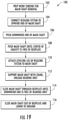
- Fig. 19 provides a flowchart representation of a method embodiment 100 in accordance with the present invention for removing an installed main shaft 34 and attached main bearing assembly 46 from the bedplate 40 in the field with the nacelle 16 remaining attached to the tower 12, or removed from the tower and placed at ground level for servicing.
- Step 102 involves preparing the wind turbine 10 for removal of the main shaft 34. This may include any one or combination of removing the blades 22 and rotor hub 20, removing various panels/wall of the nacelle 16 to expose the bedplate 40, removing the generator 24, removing the gearbox 38, arranging a crane 78 ( Fig.
- the method 100 may be practiced without removing the generator 24 in certain wind turbine designs.
- the rigging system 70 may include multiple "legs" 72, 74 in the form of chains, cables, webbing, slings, and the like, attachable to a cable on the crane 78 by any suitable conventional means (e.g., a turnbuckle).
- a turnbuckle any suitable conventional means
- One or more of these legs 72, 74 are connected to the upwind end 42 in a manner sufficient for the crane to support the full load of the upwind end 42 without the upwind end 42 rolling.
- the first leg 72 and second leg 74 are connected (e.g., using turnbuckles or other suitable devices) to preexisting holes in the rotor flange 36 at upper, opposite sides of the flange 36.
- step 106 involves pushing the downwind end 44 of the main shaft 34 at least partway through the bedplate 40.
- This "pushing" may be accomplished by electrical, hydraulic, pneumatic, or electro/hydraulic motive means.
- a hydraulic ram assembly 82 is configured at the downwind end 44 for this purpose, as explained in greater detail below.
- Fig. 5 depicts the upwind end 42 of the main shaft 34 being pushed out of the bedplate 40 to the extent that the main bearing assembly 46 (e.g., the TRB assembly) has been unseated and is partially out of the bedplate 40.
- the main bearing assembly 46 e.g., the TRB assembly
- the main shaft 34 is slid through the bedplate 40 at least until a center of gravity of the main shaft 34 and main bearing assembly 46 are free of the bedplate 40, as depicted in Fig. 6 .
- the axial location of the center of gravity is predefined and will vary depending on the size of the mains shaft, the main bearing assembly, materials, and so forth.
- a "leveling" leg 76 of the rigging system 70 is attached to the main shaft 34 at a location such that the center of gravity is located between the leveling leg 76 and the first and second legs 72, 74 of the rigging system 70.
- the leveling leg 76 is preferably adjustable (manually or remotely) for balancing the main shaft 34. In this manner, the main shaft 34 can be balanced and eventually fully supported by the crane 70 in an essentially horizontal orientation ( Fig. 8 ).
- the leveling leg 76 is depicted as an adjustable sling or cradle that wraps around the main shaft 34. Any suitable rigging device that supports the main shaft at the desired axial location may be used for this purpose.
- the main shaft 34 is fully supported to unload the bearing unit 48 at the upwind side 42 of the bedplate.
- the main shaft 34 can then be slid completely out of the bedplate 40 with the crane 78 (step 114), until the downwind end is free of the bearing unit 48, as depicted for example in Fig. 8 .
- the main shaft 34 and main bearing assembly 46 are supported by the rigging system in a horizontal and balanced orientation during this process.
- step 116 the main shaft 34 and attached main bearing assembly 46 can be lowered to the ground, at which time repair/replacement of the main bearing assembly 46 can be done.
- the present invention also encompasses a method 200 for installing a main shaft 34 and attached main bearing assembly 46 for a wind turbine 10 in a bedplate 40 installed atop a wind turbine tower 12 in the field, wherein a gearbox 38 has been removed from the bedplate 40.
- the installation method 200 is essentially the reverse of the removal method 100.
- step 202 necessary preparations are made to the wind turbine for the installation.
- the leveling leg 76 of the rigging system 70 is connected to the main shaft 34 at a location such that a center of gravity of the main shaft 34 and bearing assembly 46 is located between the leveling leg 76 and the first/second legs 72, 74 of the rigging system 70. If not yet done, the rigging system 70 is connected to the crane cable, and the main shaft 34 is raised in a balanced, horizontal orientation.
- the main shaft 34 is slid through the bedplate until the downwind end 44 of the main shaft is positioned at the bearing unit 48 fixed in the bedplate 40.
- step 208 the load of the downwind end 44 is transferred to the bearing unit, and at step 210, the leveling leg 76 is removed from the main shaft 34 so that the mains shaft can be pulled into the bedplate 40.
- the downwind end 44 is "pulled” to further slide the main shaft into the bedplate 40 until the main bearing assembly 46 is seated.
- the pull system hydraulic ram assembly 82 discussed above, or other pull system means, can be operated in reverse for this purpose, or any other suitable electrical, hydraulic, or electric/hydraulic system may be used for this purpose.
- the remaining legs 72, 74 of the rigging system 70 can be removed from the main shaft 70.
- the shaft can be slide further into the bedplate 40 with the hydraulic ram assembly 82 if needed.
- the effective length of the downwind end 44 of the main shaft 34 may be increased, for example by the addition of the support elements 90, to ensure that the downwind end 44 is supported by the bearing unit 48 prior to pulling the downwind end 44 of the main shaft 34.
- FIG. 15 depicts the hydraulic ram assembly 82 in a "push" configuration.
- a specifically designed ring or partial arc component 85 is mounted to the bedplate 40 around the main shaft 34 at the downwind end 44.
- a plurality of rods 86 (depending on the number of hydraulic cylinders used) are threaded into this ring at equally circumferentially spaced locations. These rods 86 may be threaded along the length thereof. In the depicted embodiment, three rods 86 are spaced around the ring 85.
- a plate 88 is designed with holes corresponding to the locations of the rods 86 on the ring 85, wherein the plate is slidable onto the rods 86.
- the plate 88 can have any shape, such as circular. In the depicted embodiment, the plate 88 is star-shaped with an arm at leach of the rod 86 locations.
- a hydraulic cylinder 84 is mounted on the plate 88 at each hole location.
- the hydraulic cylinders 84 are single acting "hollow" cylinders and mounted on the plate 88 such that a ram 87 of each cylinder 84 moves in a direction away from the plate 88 when actuated.
- the rod 86 runs through the cylinder 84 and ram 87.
- Suitable hydraulic cylinders 84 are commercially available from different manufacturers, including ENERPAC.
- Fig. 15 depicts an initial position of the hydraulic ram assembly 82 in the push configuration
- Fig. 16 depicts an initial position of the hydraulic ram assembly 82 in the push configuration
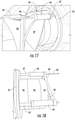
- Fig. 17 depicts the hydraulic ram assembly 82 configured in a "pull" configuration for pulling the downwind end 44 of the main shaft through the bedplate 40 for the installation method 220 described above.
- the hydraulic rams 84 are single action rams as discussed above.
- the orientation of the plate 88 and hydraulic cylinders 84 on the rods 86 is reversed as compared to Fig. 15 such that the rams 87 act against the ring 85 and the hydraulic cylinders 84 (and attached plate 88) are locked in position by stops (e.g., nuts) on the rods 86.
- An inner plate 89 (a "pull" plate) may be fixed to the downwind end 44 of the main shaft 34 (or end support ring 94) to provide a better surface for fixing the plate 88 relative to the main shaft 34.
- Fig. 17 depicts the hydraulic ram assembly 82 as it is being configured in the pull position
- Fig. 18 depicts the hydraulic ram assembly 82 and main shaft 34 at the end of the pull stroke of the hydraulic cylinders 84, wherein the main shaft 34 assumes a final position in the bedplate 40 corresponding to Fig. 4 where the main bearing assembly 46 is seated at its operation position within the bedplate 40.
- the hydraulic ram assembly 82 can be dismantled from the main shaft 34 and the support elements 90 removed.
- the assist motive system is illustrated in the figures as the hydraulic ram assembly 82 for illustrative purposes only.
- the assist system may be any one or combination of an electrical, hydraulic, pneumatic, or electro/hydraulic system configured in a push mode at the downwind end of the main shaft.
- An embodiment of the means used to extend the cylindrical profile of the main shaft 34 to ensure that the end of the main shaft 34 remains fully supported by the bearing unit 48 at the downwind end 44 of the bedplate 40 until load is transferred fully to the crane 78 is the support elements 90 discussed above and depicted in greater detail in Figs. 9 through 12 .
- Fig. 9 depicts an embodiment of a main shaft 34 with a main bearing assembly 46 fitted thereon adjacent the upwind end thereof.
- the main shaft 34 tapers radially inward just aft of the bearing surface 91 that engages the bearing unit 48 when the main shaft 34 is configured in the bedplate 40.
- the shaft would "drop" to a certain degree onto the radially reduced aft section and cant to a non-horizontal orientation within the bedplate 40, making further removal of the mains shaft difficult.
- the opposite action would occur upon installation of the shaft without the support elements 90.
- the support elements 90 essentially define an extension 92 ( Fig. 10 ) along the radially reduced aft section of the main shaft 34 that ensures the end of the main shaft 34 remains fully supported on the bearing unit 48 in a horizontal orientation of the main shaft 34 until the full load of the mains shaft 34 and main bearing assembly 46 is borne by the rigging system 70 and crane 78.
- This extension 92 may be, for example, a full cylindrical extension that completely encircles the main shaft 34, or a partial semi-circular extension around a bottom portion of the main shaft 34.
- the extension 92 may have a continuous surface, or a discontinuous surface (e.g., a cage-like structure).
- the extension could be defined by one or more axially extending planks or strip members. It should be appreciated that various support element 90 designs can be configured to meet the need for supporting the end of the main shaft 34 on the bearing unit 48.
- the cylindrical support elements 90 and full cylindrical extension 92 illustrated in the present figures is for illustrative purposes only
- the support elements 90 include one or more cylindrical rings 96, 98 that slide onto or are fitted onto the main shaft 34 around the reduced diameter section thereof.
- an inner support ring 96 ( Figs. 11 and 13 ) may have a tapered inner diameter (or other non-cylindrical profile) at one end thereof that essentially matches the taper (or other profile) on the main shaft 34, as depicted in Fig. 11 , thereby extending the cylindrical extension 92 to include the tapered region of the main shaft 34.
- An adjacent outer support ring 98 may be fitted onto the shaft 34 and extend essentially to the downwind end 44 thereof.
- inner and outer support rings 96, 98 could be replaced by a single ring, a partial arc, or any combination thereof.
- the support elements 90 may also include an end support ring 94 ( Figs. 11 and 14 ) that bolts to the downwind end 44 of the main shaft and extends the cylindrical extension 92 past the downwind end 44, as can be appreciated from Fig. 11 .
- the end support ring 94 may have a diameter that matches the diameter of the main shaft 34 with inner and outer rings 96, 98 fitted thereon.
- a single support element 90 configured as an end-cap 93 could also serve all of the functions of the rings 94, 96, and 98, as depicted in the alternative in Fig. 11 .
- the end-cap 93 can be formed as an integral or multi-component element with an end ring section 95 and a cylindrical wall section 97.
- the various support elements 90 may be formed of a material having a low coefficient of friction, yet sturdy enough to support the main shaft 34 on the bearing unit 48 without significant deformation.
Landscapes
- Engineering & Computer Science (AREA)
- Life Sciences & Earth Sciences (AREA)
- Sustainable Development (AREA)
- Sustainable Energy (AREA)
- Chemical & Material Sciences (AREA)
- Combustion & Propulsion (AREA)
- Mechanical Engineering (AREA)
- General Engineering & Computer Science (AREA)
- Wind Motors (AREA)
Description
- The present disclosure relates generally to wind turbines, and more particularly to systems and methods for removing and/or installing a main shaft to and from a nacelle located atop a wind turbine tower.
- Wind power is considered one of the cleanest, most environmentally friendly energy sources presently available, and wind turbines have gained increased attention in this regard. A modern wind turbine typically includes a tower, a generator, a gearbox, a nacelle, and one or more rotor blades. The nacelle includes a rotor assembly coupled to the gearbox and to the generator. The rotor assembly and the gearbox are mounted on a bedplate support frame located within the nacelle. In many wind turbines, the gearbox is mounted to the bedplate via one or more torque supports or arms. The rotor blades capture kinetic energy of wind using known airfoil principles and transmit the kinetic energy in the form of rotational energy so as to turn a main shaft coupling the rotor blades to the gearbox, or if a gearbox is not used, directly to the generator. The generator then converts the mechanical energy to electrical energy that may be deployed to a utility grid.
- More specifically, the majority of commercially available wind turbines utilize multi-stage geared drivetrains to connect the turbine blades to an electrical generator. The wind turns the turbine blades, which spin a low speed shaft, i.e. the main shaft. The main shaft is coupled to an input shaft of a gearbox, which has a higher speed output shaft connected to a generator. Thus, the geared drivetrain aims to increase the velocity of the mechanical motion. Further, the gearbox and the generator are typically supported by one or more bearings and mounted to the bedplate via one or more torque arms or supports.
EP 1 101 934 A2 relates to a wind turbine with a movable on-board crane. - Over time, the main shaft and associated bearings may become worn and/or damaged due to loads and forces from the wind acting on the wind turbine components. Unfortunately, repair of the main shaft and/or the main bearing assembly often requires the turbine head (machine head) to be removed from atop the nacelle and transported to a factory wherein the bedplate is stood up vertically to remove the main shaft and bearing assembly, which is a very time-consuming and expensive procedure.
-
U.S. Pat. No. 8,696,302 discloses a method for repairing or replacing a main bearing on a wind turbine without removing the rotor and main shaft. This method is not suited for wind turbine designs wherein bearing replacement or repair requires removal of the rotor and main shaft. -
U.S. Pat. No. 8,108,997 discloses a method for stabilizing the main shaft within the bedplate on a single bearing unit to repair or replace the gear box. This method is not suited for a procedure that requires removal of the rotor and main shaft to replace or repair the main bearing assembly. - To date, there has been no viable method for repairing, replacing, or upgrading a dual main bearing unit seated in a bedplate uptower in the field wherein the procedure requires removal of the rotor and main shaft from the bedplate.
- Thus, the industry is in need of new and improved systems and methods for repairing, replacing, or upgrading the main shaft bearing seated in the bedplate of the wind turbine in the field, wherein the bedplate remains installed in a horizontal position atop the tower, or is removed from the tower in the field.
- Aspects and advantages of the invention will be set forth in part in the following description, or may be obvious from the description, or may be learned through practice of the invention.
- In one aspect, the present invention is directed to a system and method wherein rigging equipment and specialized tooling are used to replace, repair, or upgrade the main bearing assembly in the field. The tooling and rigging allow the main shaft to be pushed out of its bearing seats in the bedplate while being supported by the rigging (and a crane) and the specialized tools. Once the main shaft is free of the bedplate, it can be lowered to the ground for repair or replacement of the main bearing. Alternatively, a new main shaft with bearing assembly can be installed in a reverse method according to the invention. The commercial advantages of the method are substantial as compared to taking the machine head down from the tower and transporting the machine head to a remote facility where the main shaft and bearing assembly is pulled from the bedplate.
- In this regard, a method of the invention is provided for removing an installed main shaft and attached main bearing assembly of a wind turbine from a bedplate in the field, wherein a rotor has been removed from the main shaft, a downwind end of the main shaft has been disconnected from a gearbox, and the gearbox has been removed from the bedplate. The method includes connecting a rigging system to an upwind end of the main shaft, wherein the rigging system is suspended from a crane. A downwind end of the main shaft is pushed partway through the bedplate, wherein the main shaft at the downwind end is supported by a bearing unit fixed in the bedplate and the main shaft at the upwind end is supported by the rigging system. The main shaft is pushed through the bedplate until a location on the main shaft corresponding to a center of gravity of the main shaft and main bearing assembly are free of an upwind end of the bedplate. A leveling leg of the rigging system is then attached to the main shaft at a location such that the center of gravity is located between the leveling leg and the rigging system at the upwind end of the main shaft. With the crane, the main shaft is supported to unload the bearing unit and slide the main shaft until the downwind end is free of the bearing unit. Then, with the crane fully supporting the main shaft, the shaft is horizontally slid out from the bedplate. At this point, the main shaft and attached main bearing assembly can be lowered to the ground (if the procedure is performed atop the tower) for repair or replacement of the bearing assembly.
- In a particular embodiment, the leveling leg of the rigging system is adjustable in length, and the method includes adjusting the length of the leveling leg to obtain a horizontal and balanced orientation of the main shaft as it is slid out from the bedplate.
- The downwind end of the main shaft may be pushed by various systems, such as any one or combination of an electrical, hydraulic, pneumatic, or electro/hydraulic motive system mounted to the bedplate at the downwind end of the main shaft. This system may have a push stroke such that the center of gravity of the main shaft and main bearing assembly is free of the bearing unit before an end of the push stroke. The system may be mounted to a housing of the bearing unit at the downwind end of the main shaft.
- The method may also include increasing an effective length of the downwind end of the main shaft to ensure that the downwind end is supported by the bearing unit at least until the center of gravity of the main shaft and bearing assembly are free of the upwind end of the bedplate. The effective length of the downwind end of the main shaft may be increased by adding support elements to the main shaft. One embodiment of these support elements may include one or more full or partial cylindrical elements that at least partially encircle and support the main shaft. In a certain embodiment, the downwind end of the main shaft may have a tapered or other profile, and the support elements form an additional supporting surface around the profile for being supported by the bearing unit.
- The invention also encompasses a method for installing a main shaft and attached main bearing assembly for a wind turbine in a in the field, wherein a gearbox has been removed from the bedplate. This installation method includes connecting a rigging system to an upwind end of the main shaft, the rigging system suspended from a crane. A leveling leg of the rigging system is attached to the main shaft at a location such that a center of gravity of the main shaft and bearing assembly is located between the leveling leg and the rigging system at the upwind end of the main shaft, and the main shaft is balanced in a horizontal orientation. With the crane, the main shaft is fully supported slid through the bedplate until a downwind end of the main shaft is positioned at a bearing unit fixed in the bedplate. The load of the downwind end of the main shaft in transferred to the bearing unit and the leveling leg of the rigging system is removed from the main shaft. The downwind end of the main shaft is then pulled until the bearing assembly is seated in the bedplate. The rigging system can then be removed from the upwind end of the main shaft.
- The method may include adjusting a length of the leveling leg of the rigging system to achieve the balanced and horizontal orientation of the main shaft prior to sliding the main shaft through the bedplate.
- The downwind end of the main shaft may be pulled by various systems, such as any one or combination of an electrical, hydraulic, pneumatic, or electro/hydraulic motive system mounted to the bedplate at the downwind end of the main shaft.
- An embodiment may include increasing an effective length of the downwind end of the main shaft to ensure that the downwind end is supported by the bearing unit prior to pulling the downwind end of the main shaft. This may be accomplished by adding one or more support elements to the main shaft. These support elements may be full or partial cylindrical elements that at least partially encircle the main shaft.
- These and other features, aspects and advantages of the present invention will become better understood with reference to the following description and appended claims. The accompanying drawings, which are incorporated in and constitute a part of this specification, illustrate embodiments of the invention and, together with the description, serve to explain the principles of the invention.
- A full and enabling disclosure of the present invention, including the best mode thereof, directed to one of ordinary skill in the art, is set forth in the specification, which makes reference to the appended figures, in which:
-
Fig. 1 is a perspective view of a conventional wind turbine; -
Fig. 2 is a perspective view of a simplified, internal view of one embodiment of a nacelle of a conventional wind turbine; -
Fig. 3 is a perspective view of one embodiment of a drivetrain assembly particularly illustrating the main shaft and main bearing assembly; -
Fig. 4 is a perspective view of initial steps for pulling the main shaft from the wind turbine bedplate in accordance with aspects of the invention; -
Fig. 5 is a perspective view of additional steps for pulling the main shaft from the wind turbine bedplate; -
Fig. 6 is a perspective view of still further steps for pulling the main shaft from the wind turbine bedplate; -
Fig. 7 is a perspective view of additional steps for pulling the main shaft from the wind turbine bedplate; -
Fig. 8 is a perspective view of the main shaft removed from the bedplate and supported by a crane; -
Fig. 9 is a perspective view of a main shaft prior to installation of support elements thereon; -
Fig. 10 is a perspective view of the main shaft ofFig. 9 with the support elements installed on the downwind end thereof; -
Fig. 11 is a diagram view of a main shaft with support elements to define a cylindrical extension region on the downwind end of the main shaft; -
Fig. 12 is a perspective view of the outer ring member of the support elements; -
Fig. 13 is a perspective view of the inner ring member of the support elements; -
Fig. 14 is a perspective view of the support ring member of the outer support elements; -
Fig. 15 is a perspective view of a hydraulic ram assembly in a push configuration for pushing the downwind end of the main shaft through the bedplate; -
Fig. 16 is a perspective view of the hydraulic ram assembly ofFig. 15 at the end of its push stroke; -
Fig. 17 is a perspective view of the hydraulic ram assembly in a pull configuration for pulling the downwind end of the main shaft into the bedplate; -
Fig. 18 is a perspective view of the hydraulic ram assembly ofFig. 17 at the end of its pull stroke; -
Fig. 19 is a flow chart of a method embodiment for removal of the main shaft from the wind turbine bedplate; and -
Fig. 20 is a flow chart of a method embodiment for installation of the main shaft in the wind turbine bedplate. - Reference now will be made in detail to embodiments of the invention, one or more examples of which are illustrated in the drawings. Each example is provided by way of explanation of the invention, not limitation of the invention. In fact, it will be apparent to those skilled in the art that various modifications and variations can be made the scope of protection being defined by the appended claims.
- Generally, the present invention is directed to methods for installation and/or removal of the main shaft (with attached main bearing assembly) from a bedplate (e.g., a single piece forged bedplate) in the field, wherein the nacelle (machine head) remains atop the tower or is removed from the tower for servicing at ground level in the field. The methods provide significant commercial advantages in terms of time and expense for maintenance procedures that require removal of the main shaft from the machine head, such as repair/replacement of the main bearing assembly fitted on the shaft. Aspects of the present inventive methods are described below with reference to the drawings.
- Referring now to the drawings,
Fig. 1 illustrates a perspective view of one embodiment of awind turbine 10 relevant to the present discussion. As shown, thewind turbine 10 generally includes atower 12 extending from asupport surface 14, a nacelle 16 (also referred to as a machine head) mounted on thetower 12, and arotor 18 coupled to thenacelle 16. Therotor 18 includes arotatable hub 20 and at least onerotor blade 22 coupled to and extending outwardly from thehub 20. For example, in the illustrated embodiment, therotor 18 includes threerotor blades 22. However, in an alternative embodiment, therotor 18 may include more or less than threerotor blades 22. Eachrotor blade 22 may be spaced about thehub 20 to facilitate rotating therotor 18 to enable kinetic energy to be transferred from the wind into usable mechanical energy, and subsequently, electrical energy. For instance, thehub 20 may be rotatably coupled to an electric generator 24 (Fig. 2 ) positioned within thenacelle 16 to permit electrical energy to be produced. - The
wind turbine 10 may also include awind turbine controller 26 centralized within thenacelle 16. However, in other embodiments, thecontroller 26 may be located within any other component of thewind turbine 10 or at a location outside the wind turbine. Further, thecontroller 26 may be communicatively coupled to any number of the components of thewind turbine 10 in order to control the components thereof. As such, thecontroller 26 may include a computer or other suitable processing unit. Thus, in several embodiments, thecontroller 26 may include suitable computer-readable instructions that, when implemented, configure thecontroller 26 to perform various different functions, such as receiving, transmitting and/or executing wind turbine control signals and/or performing the various method steps as described herein. - Referring now to
Fig 2 , a simplified, internal view of one embodiment of thenacelle 16 shown inFig. 1 is illustrated, particularly illustrating thedrivetrain assembly 30. As shown, thedrivetrain assembly 30 includes thegenerator 24, which may be coupled to therotor 18 for producing electrical power from the rotational energy generated by therotor 18. Therotor 18 includes amain shaft 34 coupled to thehub 20 via arotor flange 36 for rotation therewith. Themain shaft 34, in turn, is rotatably coupled to agenerator shaft 54 of thegenerator 24 through agearbox 38 connected to abedplate support frame 40 bytorque support arms 52. Thebedplate 40 is depicted in the figures, for illustrative purposes, as a single-piece bedplate made from one complete casting with bores machined therein where the bearings are seated. The present invention may also have utility with a two-piece bedplate that is split horizontally, particularly if the invention offers a time and expense advantage as compared to unbolting the split bedplate and lifting the main shaft and bearings from the bottom half of the bedplate. - Referring to
Fig. 3 , themain shaft 34 is supported by one ormore bearing assemblies end 42 of theshaft 36 is supported by themain bearing assembly 46, which in this particular embodiment is depicted as a double taper-roller bearing (TRB) assembly (themain bearing assembly 46 in the embodiment ofFigs. 9 and 10 is a single taper-roller bearing). Thismain bearing assembly 46 is fitted onto themain shaft 36 and can only be replaced or repaired by pulling themain shaft 34 from thebedplate 40. The aft "downwind"end 44 of themain shaft 36 is supported by the bearingunit 48, which in this particular embodiment is depicted as a cylindrical roller bearing (CRB) assembly. TheCRB assembly 48 is mounted to thebedplate 40, and the shaft is able to be slid axially through this bearing 48 upon being pulled from thebedplate 40. - As is generally understood, the
main shaft 34 may provide a low speed, high torque input to thegearbox 38 in response to rotation of therotor blades 22 and thehub 20. Thegearbox 38 may then be configured to convert the low speed, high torque input to a high speed, low torque output to drive thegenerator shaft 36 and, thus, thegenerator 24. - Each
rotor blade 22 may also include apitch adjustment mechanism 60 configured to rotate eachrotor blade 22 about itspitch axis 28. Further, eachpitch adjustment mechanism 60 may include a pitch drive motor 68 (e.g., any suitable electric, hydraulic, or pneumatic motor), apitch drive gearbox 62, and apitch drive pinion 64. Thepitch drive motor 68 is coupled to thepitch drive gearbox 62 to impart a mechanical force to thepitch drive gearbox 62. Similarly, thepitch drive gearbox 62 is coupled to thepitch drive pinion 64 for rotation therewith. Thepitch drive pinion 64 is in rotational engagement with a pitch bearing 66 coupled between thehub 20 and acorresponding rotor blade 22 such that rotation of thepitch drive pinion 64 causes rotation of the pitch bearing 66, thereby rotating therotor blade 22 about thepitch axis 28. Similarly, thewind turbine 10 may include one or moreyaw drive mechanisms 56 communicatively coupled to thecontroller 26, with each yaw drive mechanism(s) 56 being configured to change the angle of thenacelle 16 relative to the wind (e.g., by engaging a yaw bearing 58 of the wind turbine 10). -
Fig. 19 provides a flowchart representation of amethod embodiment 100 in accordance with the present invention for removing an installedmain shaft 34 and attachedmain bearing assembly 46 from thebedplate 40 in the field with thenacelle 16 remaining attached to thetower 12, or removed from the tower and placed at ground level for servicing. Step 102 involves preparing thewind turbine 10 for removal of themain shaft 34. This may include any one or combination of removing theblades 22 androtor hub 20, removing various panels/wall of thenacelle 16 to expose thebedplate 40, removing thegenerator 24, removing thegearbox 38, arranging a crane 78 (Fig. 8 ) at the site, staging a riggingsystem 70, and any other preparatory step or procedure that is necessitated by the wind turbine design or site location for a subsequent removal of themain shaft 34. Although it may be desired for space and safety concerns, themethod 100 may be practiced without removing thegenerator 24 in certain wind turbine designs. - At
step 104, part of the riggingsystem 70 is connected to theupwind end 44 of themain shaft 34. For example, referring toFig. 4 , the riggingsystem 70 may include multiple "legs" 72, 74 in the form of chains, cables, webbing, slings, and the like, attachable to a cable on thecrane 78 by any suitable conventional means (e.g., a turnbuckle). One or more of theselegs upwind end 42 in a manner sufficient for the crane to support the full load of theupwind end 42 without theupwind end 42 rolling. In the depicted embodiment, thefirst leg 72 andsecond leg 74 are connected (e.g., using turnbuckles or other suitable devices) to preexisting holes in therotor flange 36 at upper, opposite sides of theflange 36. - Once the rigging is connected to the crane cable and the
upwind end 42 of themain shaft 34 is supported,step 106 involves pushing thedownwind end 44 of themain shaft 34 at least partway through thebedplate 40. This "pushing" may be accomplished by electrical, hydraulic, pneumatic, or electro/hydraulic motive means. In the embodiment ofFigs. 15-18 , ahydraulic ram assembly 82 is configured at thedownwind end 44 for this purpose, as explained in greater detail below. -
Fig. 5 depicts theupwind end 42 of themain shaft 34 being pushed out of thebedplate 40 to the extent that the main bearing assembly 46 (e.g., the TRB assembly) has been unseated and is partially out of thebedplate 40. - At
step 108, themain shaft 34 is slid through thebedplate 40 at least until a center of gravity of themain shaft 34 andmain bearing assembly 46 are free of thebedplate 40, as depicted inFig. 6 . The axial location of the center of gravity is predefined and will vary depending on the size of the mains shaft, the main bearing assembly, materials, and so forth. - At
step 110, a "leveling"leg 76 of the riggingsystem 70 is attached to themain shaft 34 at a location such that the center of gravity is located between the levelingleg 76 and the first andsecond legs system 70. The levelingleg 76 is preferably adjustable (manually or remotely) for balancing themain shaft 34. In this manner, themain shaft 34 can be balanced and eventually fully supported by thecrane 70 in an essentially horizontal orientation (Fig. 8 ). In the depicted embodiment, the levelingleg 76 is depicted as an adjustable sling or cradle that wraps around themain shaft 34. Any suitable rigging device that supports the main shaft at the desired axial location may be used for this purpose. - At
step 112, with thecrane 70, themain shaft 34 is fully supported to unload the bearingunit 48 at theupwind side 42 of the bedplate. Themain shaft 34 can then be slid completely out of thebedplate 40 with the crane 78 (step 114), until the downwind end is free of the bearingunit 48, as depicted for example inFig. 8 . Themain shaft 34 andmain bearing assembly 46 are supported by the rigging system in a horizontal and balanced orientation during this process. - At this point, at
step 116, themain shaft 34 and attachedmain bearing assembly 46 can be lowered to the ground, at which time repair/replacement of themain bearing assembly 46 can be done. - With certain main shaft designs, it may be desired to increase the effective length of the
downwind end 44 of themain shaft 34 to ensure that the downwind end is supported by the bearingunit 48 at least until the center of gravity of themain shaft 34 and bearingassembly 46 are free of theupwind end 42 of thebedplate 40. Referring to the view inFig. 8 , this may be accomplished by essentially adding extension or supportelements 90 to the end of themain shaft 34 in order to extend the cylindrical length of the shaft, as explained in more detail below with reference toFigs. 9 through 14 . - Referring to
Fig. 20 , the present invention also encompasses amethod 200 for installing amain shaft 34 and attachedmain bearing assembly 46 for awind turbine 10 in abedplate 40 installed atop awind turbine tower 12 in the field, wherein agearbox 38 has been removed from thebedplate 40. Theinstallation method 200 is essentially the reverse of theremoval method 100. - At
step 202, necessary preparations are made to the wind turbine for the installation. - At
step 204, at least afirst leg 72 of the riggingsystem 70 is connected to theupwind end 42 of themain shaft 34, which may be at ground level. The levelingleg 76 of the riggingsystem 70 is connected to themain shaft 34 at a location such that a center of gravity of themain shaft 34 and bearingassembly 46 is located between the levelingleg 76 and the first/second legs system 70. If not yet done, the riggingsystem 70 is connected to the crane cable, and themain shaft 34 is raised in a balanced, horizontal orientation. - At
step 206, with thecrane 78 fully supporting themain shaft 34, themain shaft 34 is slid through the bedplate until thedownwind end 44 of the main shaft is positioned at the bearingunit 48 fixed in thebedplate 40. - At
step 208, the load of thedownwind end 44 is transferred to the bearing unit, and atstep 210, the levelingleg 76 is removed from themain shaft 34 so that the mains shaft can be pulled into thebedplate 40. - At
step 212, thedownwind end 44 is "pulled" to further slide the main shaft into thebedplate 40 until themain bearing assembly 46 is seated. The pull systemhydraulic ram assembly 82 discussed above, or other pull system means, can be operated in reverse for this purpose, or any other suitable electrical, hydraulic, or electric/hydraulic system may be used for this purpose. - At
step 214, the remaininglegs system 70 can be removed from themain shaft 70. The shaft can be slide further into thebedplate 40 with thehydraulic ram assembly 82 if needed. - As discussed, the effective length of the
downwind end 44 of themain shaft 34 may be increased, for example by the addition of thesupport elements 90, to ensure that thedownwind end 44 is supported by the bearingunit 48 prior to pulling thedownwind end 44 of themain shaft 34. - Operation of one embodiment for pushing the
main shaft 34 from thedownwind end 44 thereof in theremoval method 100, and pulling themain shaft 34 at thedownwind end 44 in the installation method 220, is depicted inFigs. 15 through 18 , in whichFig. 15 depicts thehydraulic ram assembly 82 in a "push" configuration. Initially, a specifically designed ring orpartial arc component 85 is mounted to thebedplate 40 around themain shaft 34 at thedownwind end 44. A plurality of rods 86 (depending on the number of hydraulic cylinders used) are threaded into this ring at equally circumferentially spaced locations. Theserods 86 may be threaded along the length thereof. In the depicted embodiment, threerods 86 are spaced around thering 85. Aplate 88 is designed with holes corresponding to the locations of therods 86 on thering 85, wherein the plate is slidable onto therods 86. Theplate 88 can have any shape, such as circular. In the depicted embodiment, theplate 88 is star-shaped with an arm at leach of therod 86 locations. - Referring to
Figs. 15 through 18 , ahydraulic cylinder 84 is mounted on theplate 88 at each hole location. In the depicted embodiment, thehydraulic cylinders 84 are single acting "hollow" cylinders and mounted on theplate 88 such that aram 87 of eachcylinder 84 moves in a direction away from theplate 88 when actuated. At each location, therod 86 runs through thecylinder 84 andram 87. Suitablehydraulic cylinders 84 are commercially available from different manufacturers, including ENERPAC. - In the push configuration of
Figs. 15 and 16 , theplate 88 andhydraulic cylinders 84 are slid onto therods 86 such that theplate 88 bears against thedownwind end 44 of the main shaft 34or an end support ring 94 (discussed below) attached to the end of themain shaft 34. The position of therams 87 on therods 86 is locked in place by a nut threaded onto therods 86 against which therams 87 bear upon actuation of thecylinders 84. Other locking devices on therods 86 can be used for this purpose.Fig. 15 depicts an initial position of thehydraulic ram assembly 82 in the push configuration, andFig. 16 depicts a final position wherein theplate 88 has "bottomed out" against thering 85 and themain shaft 34 has been pushed into thebedplate 40. The push stroke of thehydraulic cylinders 84 is thus equal to effective displacement distance of therams 87. Prior to downwind end 44 of themain shaft 34 reaching the position depicted inFig. 16 , themain bearing assembly 46 has unseated from thebedplate 40 and the levelingleg 76 of the rigging system has been attached to the main shaft, as depicted inFig. 6 . -
Fig. 17 depicts thehydraulic ram assembly 82 configured in a "pull" configuration for pulling thedownwind end 44 of the main shaft through thebedplate 40 for the installation method 220 described above. In the depicted embodiment, thehydraulic rams 84 are single action rams as discussed above. Thus, in the pull configuration, the orientation of theplate 88 andhydraulic cylinders 84 on therods 86 is reversed as compared toFig. 15 such that therams 87 act against thering 85 and the hydraulic cylinders 84 (and attached plate 88) are locked in position by stops (e.g., nuts) on therods 86. An inner plate 89 (a "pull" plate) may be fixed to thedownwind end 44 of the main shaft 34 (or end support ring 94) to provide a better surface for fixing theplate 88 relative to themain shaft 34. -
Fig. 17 depicts thehydraulic ram assembly 82 as it is being configured in the pull position, andFig. 18 depicts thehydraulic ram assembly 82 andmain shaft 34 at the end of the pull stroke of thehydraulic cylinders 84, wherein themain shaft 34 assumes a final position in thebedplate 40 corresponding toFig. 4 where themain bearing assembly 46 is seated at its operation position within thebedplate 40. At this point, thehydraulic ram assembly 82 can be dismantled from themain shaft 34 and thesupport elements 90 removed. - The assist motive system is illustrated in the figures as the
hydraulic ram assembly 82 for illustrative purposes only. As mentioned, the assist system may be any one or combination of an electrical, hydraulic, pneumatic, or electro/hydraulic system configured in a push mode at the downwind end of the main shaft. - An embodiment of the means used to extend the cylindrical profile of the
main shaft 34 to ensure that the end of themain shaft 34 remains fully supported by the bearingunit 48 at thedownwind end 44 of thebedplate 40 until load is transferred fully to thecrane 78 is thesupport elements 90 discussed above and depicted in greater detail inFigs. 9 through 12 . -
Fig. 9 depicts an embodiment of amain shaft 34 with amain bearing assembly 46 fitted thereon adjacent the upwind end thereof. At thedownwind end 44 it can be seen that themain shaft 34 tapers radially inward just aft of the bearingsurface 91 that engages the bearingunit 48 when themain shaft 34 is configured in thebedplate 40. Without thesupport elements 90 fitted onto this section of themain shaft 34, when the bearingsurface 91 is pushed past the bearingunit 48, the shaft would "drop" to a certain degree onto the radially reduced aft section and cant to a non-horizontal orientation within thebedplate 40, making further removal of the mains shaft difficult. The opposite action would occur upon installation of the shaft without thesupport elements 90. - The
support elements 90 essentially define an extension 92 (Fig. 10 ) along the radially reduced aft section of themain shaft 34 that ensures the end of themain shaft 34 remains fully supported on the bearingunit 48 in a horizontal orientation of themain shaft 34 until the full load of themains shaft 34 andmain bearing assembly 46 is borne by the riggingsystem 70 andcrane 78. Thisextension 92 may be, for example, a full cylindrical extension that completely encircles themain shaft 34, or a partial semi-circular extension around a bottom portion of themain shaft 34. Theextension 92 may have a continuous surface, or a discontinuous surface (e.g., a cage-like structure). The extension could be defined by one or more axially extending planks or strip members. It should be appreciated thatvarious support element 90 designs can be configured to meet the need for supporting the end of themain shaft 34 on the bearingunit 48. Thecylindrical support elements 90 and fullcylindrical extension 92 illustrated in the present figures is for illustrative purposes only. - In the depicted embodiment, the
support elements 90 include one or morecylindrical rings main shaft 34 around the reduced diameter section thereof. For example, an inner support ring 96 (Figs. 11 and 13 ) may have a tapered inner diameter (or other non-cylindrical profile) at one end thereof that essentially matches the taper (or other profile) on themain shaft 34, as depicted inFig. 11 , thereby extending thecylindrical extension 92 to include the tapered region of themain shaft 34. An adjacentouter support ring 98 may be fitted onto theshaft 34 and extend essentially to thedownwind end 44 thereof. - It should be appreciated that the inner and outer support rings 96, 98 could be replaced by a single ring, a partial arc, or any combination thereof.
- The
support elements 90 may also include an end support ring 94 (Figs. 11 and 14 ) that bolts to thedownwind end 44 of the main shaft and extends thecylindrical extension 92 past thedownwind end 44, as can be appreciated fromFig. 11 . Theend support ring 94 may have a diameter that matches the diameter of themain shaft 34 with inner andouter rings - It should be appreciated that a
single support element 90 configured as an end-cap 93 could also serve all of the functions of therings Fig. 11 . The end-cap 93 can be formed as an integral or multi-component element with anend ring section 95 and acylindrical wall section 97. - The
various support elements 90 may be formed of a material having a low coefficient of friction, yet sturdy enough to support themain shaft 34 on the bearingunit 48 without significant deformation. - This written description uses examples to disclose the invention, including the best mode, and also to enable any person skilled in the art to practice the invention, including making and using any devices or systems and performing any incorporated methods. The scope of protection being defined by the appended claims.
Claims (15)
- A method (100) for removing an installed main shaft (34) and attached main bearing assembly (46) of a wind turbine (10) from a bedplate (40) in the field, wherein a rotor (18) has been removed from an upwind end (42) of the main shaft, a downwind end (44) of the main shaft has been disconnected from a gearbox (38), and the gearbox has been removed from the bedplate, the method comprising:connecting a rigging system (70) to the upwind end of the main shaft, the rigging system suspended from a crane (78);pushing the downwind end of the main shaft partway through the bedplate, wherein the main shaft at the downwind end is supported by a bearing unit (48) fixed in the bedplate and the main shaft at the upwind end is supported by the rigging system;pushing the main shaft through the bedplate until a location on the main shaft corresponding to a center of gravity of the main shaft and main bearing assembly are free of an upwind end of the bedplate;attaching a leveling leg (76) of the rigging system to the main shaft at a location such that the center of gravity is located between the leveling leg and the rigging at the upwind end of the main shaft;with the crane, supporting the main shaft to unload the bearing unit and slide the main shaft until the downwind end is free of the bearing unit;with the crane fully supporting the main shaft, horizontally sliding the main shaft out from the bedplate.
- The method (100) of claim 1, wherein the leveling leg (76) of the rigging system (70) is adjustable in length, the method comprising adjusting the length of the leveling leg to obtain a horizontal and balanced orientation of the main shaft (34) as it is slid out from the bedplate (40).
- The method (100) of claims 1 or 2, wherein the downwind end (44) of the main shaft (34) is pushed by any one or combination of an electrical, hydraulic, pneumatic, or electro/hydraulic motive system (82) configured at the downwind end of the main shaft.
- The method (100) of claim 3, wherein the motive system includes a push stroke such that the center of gravity of the main shaft (34) and main bearing assembly (46) is free of the bearing unit (48) before an end of the push stroke.
- The method (100) of claim 4, wherein the motive system is a hydraulic ram assembly (82) mounted to the bedplate (40) at the downwind end (44) of the main shaft (34).
- The method (100) of any one of claims 1 through 5, further comprising increasing an effective length of the downwind end (44) of the main shaft to ensure that the downwind end is supported by the bearing unit (48) at least until the center of gravity of the main shaft (34) and bearing assembly (46) are free of the upwind end (42) of the bedplate (40).
- The method (100) of claim 6, wherein the effective length of the downwind end (44) of the main shaft (34) is increased by adding one or more support elements (90) to the main shaft (34).
- The method (100) of claim 7, wherein the support elements (90) comprise one or more full or partial cylindrical elements (92, 97) that at least partially encircle the main shaft (34).
- The method (100) of any one of claims 1 through 8, wherein the rigging system (70) at the upwind end (42) of the main shaft (34) includes one or more rigging legs (72) attached to a rotor flange (36) at the upwind end of the main shaft.
- A method (200) for installing a main shaft (34) and attached main bearing assembly (46) for a wind turbine (10) in a bedplate (40) in the field, wherein a gearbox (38) has been removed from the bedplate, the method comprising:connecting a rigging system (70) to an upwind end (42) of the main shaft, the rigging system suspended from a crane (78);attaching a leveling leg (76) of the rigging system to the main shaft at a location such that a center of gravity of the main shaft and bearing assembly is located between the leveling leg and the rigging system at the upwind end of the main shaft, and the main shaft is balanced in a horizontal orientation;with the crane, fully supporting and moving the main shaft through the bedplate until a downwind end (44) of the main shaft is positioned at a bearing unit (48) fixed in the bedplate;transferring load of the downwind end of the main shaft to the bearing unit and removing the leveling leg of the rigging system;pulling the downwind end of the main shaft until the bearing assembly is seated in the bedplate; andremoving the rigging system from the upwind end of the main shaft.
- The method (200) of claim 10, further comprising adjusting a length of the leveling leg (76) of the rigging system (70) to achieve the balanced and horizontal orientation of the main shaft (34).
- The method (200) of claims 10 or 11, wherein the downwind end (44) of the main shaft (34) is pulled by any one or combination of an electrical, hydraulic, pneumatic, or electro/hydraulic motive system (82) configured at the downwind end of the main shaft.
- The method (200) of any one of claims 10 through 12, further comprising increasing an effective length of the downwind end (44) of the main shaft (34) to ensure that the downwind end is supported by the bearing unit (48) prior to pulling the downwind end of the main shaft.
- The method (200) of claim 13, wherein the effective length of the downwind end (44) of the main shaft (34) is increased by adding one or more support elements (90) to the main shaft.
- The method (200) of claim 14, wherein the support elements (90) comprise one or more full or partial cylindrical elements (92, 97) that at least partially encircle the main shaft (34).
Applications Claiming Priority (2)
| Application Number | Priority Date | Filing Date | Title |
|---|---|---|---|
| US15/498,760 US10337503B2 (en) | 2017-04-27 | 2017-04-27 | System and method for removing or installing a main shaft of a wind turbine with rigging |
| PCT/US2018/029704 WO2018200902A1 (en) | 2017-04-27 | 2018-04-27 | System and method for removing or installing a main shaft of a wind turbine with rigging |
Publications (3)
| Publication Number | Publication Date |
|---|---|
| EP3615795A1 EP3615795A1 (en) | 2020-03-04 |
| EP3615795A4 EP3615795A4 (en) | 2021-01-13 |
| EP3615795B1 true EP3615795B1 (en) | 2022-02-16 |
Family
ID=63916540
Family Applications (1)
| Application Number | Title | Priority Date | Filing Date |
|---|---|---|---|
| EP18791675.4A Active EP3615795B1 (en) | 2017-04-27 | 2018-04-27 | System and method for removing or installing a main shaft of a wind turbine with rigging |
Country Status (5)
| Country | Link |
|---|---|
| US (1) | US10337503B2 (en) |
| EP (1) | EP3615795B1 (en) |
| DK (1) | DK3615795T3 (en) |
| ES (1) | ES2913836T3 (en) |
| WO (1) | WO2018200902A1 (en) |
Families Citing this family (4)
| Publication number | Priority date | Publication date | Assignee | Title |
|---|---|---|---|---|
| CN108661864B (en) * | 2017-03-29 | 2022-03-22 | 通用电气公司 | Repair method for gearbox assembly for wind turbine |
| US10975732B2 (en) * | 2019-04-04 | 2021-04-13 | General Electric Company | Rotor turning device for balancing a wind turbine rotor |
| EP3722601B1 (en) * | 2019-04-08 | 2021-09-01 | Siemens Gamesa Renewable Energy Innovation & Technology, S.L. | Wind turbine |
| CA3258938A1 (en) * | 2022-07-18 | 2024-01-25 | Liftwerx Solutions Inc. | Main shaft lifting tool |
Citations (2)
| Publication number | Priority date | Publication date | Assignee | Title |
|---|---|---|---|---|
| EP1101934B1 (en) * | 1999-11-18 | 2005-01-12 | General Electric Company | Wind turbine having a movable crane in the nacelle |
| EP1825141B1 (en) * | 2004-12-17 | 2009-07-29 | NORDEX ENERGY GmbH | Wind motor with a holding device for a rotor shaft |
Family Cites Families (27)
| Publication number | Priority date | Publication date | Assignee | Title |
|---|---|---|---|---|
| EP1291521A1 (en) * | 2001-09-06 | 2003-03-12 | Turbowinds N.V./S.A. | Wind turbine nacelle with moving crane |
| ES2265743B1 (en) * | 2004-12-15 | 2008-02-01 | GAMESA INNOVATION & TECHNOLOGY, S.L. | AEROGENERATOR WITH REMOVABLE CRANE. |
| US7721434B2 (en) | 2005-07-27 | 2010-05-25 | General Electric Company | Methods and apparatus for replacing objects on horizontal shafts in elevated locations |
| US7484290B2 (en) * | 2006-02-22 | 2009-02-03 | General Electric Company | Methods and system to facilitate installation and removal of a generator rotor assembly |
| WO2007096008A1 (en) * | 2006-02-27 | 2007-08-30 | Ecotecnia Energias Renovables, S.L. | Method and system for hoisting heavy parts onto a wind turbine |
| US8590151B2 (en) * | 2006-06-30 | 2013-11-26 | Solar Turbines Inc. | System for supporting and servicing a gas turbine engine |
| DE102007062428A1 (en) * | 2007-12-20 | 2009-06-25 | Repower Systems Ag | Construction of a wind turbine |
| DK2143936T3 (en) | 2008-07-07 | 2016-03-21 | Siemens Ag | Wind turbine comprising a main bearing, and method for the replacement of the main bearing |
| US8104631B2 (en) * | 2008-07-24 | 2012-01-31 | General Electric Company | Portable crane system for wind turbine components |
| WO2010032277A1 (en) * | 2008-09-17 | 2010-03-25 | 東芝三菱電機産業システム株式会社 | Dismantling device and dismantling method of rotating electric machine |
| ES2474595T3 (en) * | 2008-09-30 | 2014-07-09 | Vestas Wind Systems A/S | Service crane for wind turbine |
| DK177083B1 (en) * | 2009-10-28 | 2011-06-27 | Liftra Aps | Device for providing access and transport of goods to and from a wind turbine construction above ground level |
| US7944079B1 (en) * | 2010-04-21 | 2011-05-17 | General Electric Company | Systems and methods for assembling a gearbox handling assembly for use in a wind turbine |
| US8789274B2 (en) * | 2010-09-23 | 2014-07-29 | Northern Power Systems, Inc. | Method and system for servicing a horizontal-axis wind power unit |
| ES2552878T3 (en) | 2010-09-30 | 2015-12-02 | Vestas Wind Systems A/S | Wind turbine with bearing support |
| US8500400B2 (en) * | 2011-09-20 | 2013-08-06 | General Electric Company | Component handling system for use in wind turbines and methods of positioning a drive train component |
| US20120131786A1 (en) * | 2011-11-18 | 2012-05-31 | Ulrich Neumann | Positioning system for use in wind turbines and methods of positioning a drive train component |
| EP2610439A1 (en) * | 2011-12-30 | 2013-07-03 | Siemens Aktiengesellschaft | Method for pulling and/or inserting a turbine bearing and device for performing the method |
| DK178900B1 (en) * | 2012-06-04 | 2017-05-08 | Liftra Ip Aps | Methods and means for establishing access to the main parts of the nacelle on a wind turbine |
| DK2690284T3 (en) | 2012-07-23 | 2015-10-05 | Siemens Ag | Wind Turbine Generator and maintenance of its main bearing |
| DK177934B9 (en) * | 2013-06-19 | 2015-01-19 | Envision Energy Denmark Aps | Assembly method for a main rotor shaft and an installation tool thereto |
| ES2778198T3 (en) * | 2013-10-04 | 2020-08-10 | Inventus Holdings Llc | Replacement of wind turbine components at the top of the tower |
| US20150135534A1 (en) * | 2013-11-21 | 2015-05-21 | General Electric Company | System and method for uptower machining of a wind turbine |
| DK201500527A1 (en) * | 2014-10-07 | 2016-04-18 | Liftra Ip Aps | Main shaft fixing trip for fixing the main shaft on a wind turbine when carrying out installation and repair work. |
| DK178541B1 (en) * | 2014-11-07 | 2016-06-06 | Envision Energy Denmark Aps | Assembly stand for assembling a gearbox unit and a main shaft of a wind turbine |
| US9757821B2 (en) * | 2015-06-30 | 2017-09-12 | General Electric Company | System and method for in-situ resurfacing of a wind turbine main rotor shaft |
| US10443572B2 (en) * | 2016-01-27 | 2019-10-15 | General Electric Company | System and method for removing or installing a main shaft of a wind turbine |
-
2017
- 2017-04-27 US US15/498,760 patent/US10337503B2/en active Active
-
2018
- 2018-04-27 EP EP18791675.4A patent/EP3615795B1/en active Active
- 2018-04-27 DK DK18791675.4T patent/DK3615795T3/en active
- 2018-04-27 ES ES18791675T patent/ES2913836T3/en active Active
- 2018-04-27 WO PCT/US2018/029704 patent/WO2018200902A1/en not_active Ceased
Patent Citations (2)
| Publication number | Priority date | Publication date | Assignee | Title |
|---|---|---|---|---|
| EP1101934B1 (en) * | 1999-11-18 | 2005-01-12 | General Electric Company | Wind turbine having a movable crane in the nacelle |
| EP1825141B1 (en) * | 2004-12-17 | 2009-07-29 | NORDEX ENERGY GmbH | Wind motor with a holding device for a rotor shaft |
Also Published As
| Publication number | Publication date |
|---|---|
| WO2018200902A1 (en) | 2018-11-01 |
| EP3615795A4 (en) | 2021-01-13 |
| DK3615795T3 (en) | 2022-05-23 |
| US20180313329A1 (en) | 2018-11-01 |
| ES2913836T3 (en) | 2022-06-06 |
| EP3615795A1 (en) | 2020-03-04 |
| US10337503B2 (en) | 2019-07-02 |
Similar Documents
| Publication | Publication Date | Title |
|---|---|---|
| US10422322B2 (en) | System and method for removing or installing a main shaft of a wind turbine with main shaft support elements | |
| EP3615793B1 (en) | System and method for removing or installing a main shaft of a wind turbine with a push/pull system configured at an end of the main shaft | |
| US10443572B2 (en) | System and method for removing or installing a main shaft of a wind turbine | |
| EP3450744B1 (en) | Method and tool for disassembling a pitch bearing from a wind turbine hub | |
| EP2775137B1 (en) | System and method for re-indexing a pitch bearing of a wind turbine | |
| US10337503B2 (en) | System and method for removing or installing a main shaft of a wind turbine with rigging | |
| EP3431751B1 (en) | System and method for suspending a rotor blade of a wind turbine uptower | |
| US10502193B2 (en) | Repair method for a gearbox assembly of a wind turbine | |
| US20210222680A1 (en) | System and method for repairing a gearbox of a wind turbine uptower | |
| US10801473B2 (en) | Hub crane assembly for a wind turbine | |
| US20180313335A1 (en) | Working platform within a nacelle of a wind turbine | |
| US12123392B2 (en) | Method of assembling or disassembling a rotor blade of a wind turbine | |
| EP3615794B1 (en) | Apparatus and method for removing or installing a bearing unit in a wind turbine bedplate with an adjustable bearing support | |
| CN114087140A (en) | Integrated system and method for maintaining components of a wind turbine | |
| EP3364023B1 (en) | System and method for removing or installing a main shaft of a wind turbine | |
| EP4224009A1 (en) | Blade segment for a rotor blade of a wind turbine | |
| EP4502369A1 (en) | Handling apparatus | |
| CN121701426A (en) | Method for replacing bearing and wind driven generator |
Legal Events
| Date | Code | Title | Description |
|---|---|---|---|
| STAA | Information on the status of an ep patent application or granted ep patent |
Free format text: STATUS: THE INTERNATIONAL PUBLICATION HAS BEEN MADE |
|
| PUAI | Public reference made under article 153(3) epc to a published international application that has entered the european phase |
Free format text: ORIGINAL CODE: 0009012 |
|
| STAA | Information on the status of an ep patent application or granted ep patent |
Free format text: STATUS: REQUEST FOR EXAMINATION WAS MADE |
|
| 17P | Request for examination filed |
Effective date: 20191125 |
|
| AK | Designated contracting states |
Kind code of ref document: A1 Designated state(s): AL AT BE BG CH CY CZ DE DK EE ES FI FR GB GR HR HU IE IS IT LI LT LU LV MC MK MT NL NO PL PT RO RS SE SI SK SM TR |
|
| RIN1 | Information on inventor provided before grant (corrected) |
Inventor name: EHERTS, KEVIN TYLER Inventor name: SIGNORE, JONATHAN PAUL Inventor name: VANDERWALKER, DARRICK ADAM Inventor name: REDD, RODNEY ROBERT II Inventor name: THOMAS, GREGORY CLARENCE Inventor name: ANDERSON, HUNTER RYAN |
|
| A4 | Supplementary search report drawn up and despatched |
Effective date: 20201211 |
|
| RIC1 | Information provided on ipc code assigned before grant |
Ipc: F03D 13/10 20160101ALI20201207BHEP Ipc: F03D 80/50 20160101AFI20201207BHEP Ipc: B23P 6/04 20060101ALI20201207BHEP Ipc: F03D 80/70 20160101ALI20201207BHEP Ipc: F03D 80/80 20160101ALI20201207BHEP |
|
| GRAP | Despatch of communication of intention to grant a patent |
Free format text: ORIGINAL CODE: EPIDOSNIGR1 |
|
| STAA | Information on the status of an ep patent application or granted ep patent |
Free format text: STATUS: GRANT OF PATENT IS INTENDED |
|
| INTG | Intention to grant announced |
Effective date: 20210924 |
|
| GRAS | Grant fee paid |
Free format text: ORIGINAL CODE: EPIDOSNIGR3 |
|
| GRAA | (expected) grant |
Free format text: ORIGINAL CODE: 0009210 |
|
| STAA | Information on the status of an ep patent application or granted ep patent |
Free format text: STATUS: THE PATENT HAS BEEN GRANTED |
|
| AK | Designated contracting states |
Kind code of ref document: B1 Designated state(s): AL AT BE BG CH CY CZ DE DK EE ES FI FR GB GR HR HU IE IS IT LI LT LU LV MC MK MT NL NO PL PT RO RS SE SI SK SM TR |
|
| REG | Reference to a national code |
Ref country code: GB Ref legal event code: FG4D |
|
| REG | Reference to a national code |
Ref country code: CH Ref legal event code: EP |
|
| REG | Reference to a national code |
Ref country code: DE Ref legal event code: R096 Ref document number: 602018030957 Country of ref document: DE |
|
| REG | Reference to a national code |
Ref country code: AT Ref legal event code: REF Ref document number: 1469029 Country of ref document: AT Kind code of ref document: T Effective date: 20220315 |
|
| REG | Reference to a national code |
Ref country code: IE Ref legal event code: FG4D |
|
| REG | Reference to a national code |
Ref country code: DK Ref legal event code: T3 Effective date: 20220518 |
|
| REG | Reference to a national code |
Ref country code: ES Ref legal event code: FG2A Ref document number: 2913836 Country of ref document: ES Kind code of ref document: T3 Effective date: 20220606 |
|
| REG | Reference to a national code |
Ref country code: LT Ref legal event code: MG9D |
|
| REG | Reference to a national code |
Ref country code: NL Ref legal event code: MP Effective date: 20220216 |
|
| REG | Reference to a national code |
Ref country code: AT Ref legal event code: MK05 Ref document number: 1469029 Country of ref document: AT Kind code of ref document: T Effective date: 20220216 |
|
| PG25 | Lapsed in a contracting state [announced via postgrant information from national office to epo] |
Ref country code: SE Free format text: LAPSE BECAUSE OF FAILURE TO SUBMIT A TRANSLATION OF THE DESCRIPTION OR TO PAY THE FEE WITHIN THE PRESCRIBED TIME-LIMIT Effective date: 20220216 Ref country code: RS Free format text: LAPSE BECAUSE OF FAILURE TO SUBMIT A TRANSLATION OF THE DESCRIPTION OR TO PAY THE FEE WITHIN THE PRESCRIBED TIME-LIMIT Effective date: 20220216 Ref country code: PT Free format text: LAPSE BECAUSE OF FAILURE TO SUBMIT A TRANSLATION OF THE DESCRIPTION OR TO PAY THE FEE WITHIN THE PRESCRIBED TIME-LIMIT Effective date: 20220616 Ref country code: NO Free format text: LAPSE BECAUSE OF FAILURE TO SUBMIT A TRANSLATION OF THE DESCRIPTION OR TO PAY THE FEE WITHIN THE PRESCRIBED TIME-LIMIT Effective date: 20220516 Ref country code: NL Free format text: LAPSE BECAUSE OF FAILURE TO SUBMIT A TRANSLATION OF THE DESCRIPTION OR TO PAY THE FEE WITHIN THE PRESCRIBED TIME-LIMIT Effective date: 20220216 Ref country code: LT Free format text: LAPSE BECAUSE OF FAILURE TO SUBMIT A TRANSLATION OF THE DESCRIPTION OR TO PAY THE FEE WITHIN THE PRESCRIBED TIME-LIMIT Effective date: 20220216 Ref country code: HR Free format text: LAPSE BECAUSE OF FAILURE TO SUBMIT A TRANSLATION OF THE DESCRIPTION OR TO PAY THE FEE WITHIN THE PRESCRIBED TIME-LIMIT Effective date: 20220216 Ref country code: BG Free format text: LAPSE BECAUSE OF FAILURE TO SUBMIT A TRANSLATION OF THE DESCRIPTION OR TO PAY THE FEE WITHIN THE PRESCRIBED TIME-LIMIT Effective date: 20220516 |
|
| PG25 | Lapsed in a contracting state [announced via postgrant information from national office to epo] |
Ref country code: PL Free format text: LAPSE BECAUSE OF FAILURE TO SUBMIT A TRANSLATION OF THE DESCRIPTION OR TO PAY THE FEE WITHIN THE PRESCRIBED TIME-LIMIT Effective date: 20220216 Ref country code: LV Free format text: LAPSE BECAUSE OF FAILURE TO SUBMIT A TRANSLATION OF THE DESCRIPTION OR TO PAY THE FEE WITHIN THE PRESCRIBED TIME-LIMIT Effective date: 20220216 Ref country code: GR Free format text: LAPSE BECAUSE OF FAILURE TO SUBMIT A TRANSLATION OF THE DESCRIPTION OR TO PAY THE FEE WITHIN THE PRESCRIBED TIME-LIMIT Effective date: 20220517 Ref country code: FI Free format text: LAPSE BECAUSE OF FAILURE TO SUBMIT A TRANSLATION OF THE DESCRIPTION OR TO PAY THE FEE WITHIN THE PRESCRIBED TIME-LIMIT Effective date: 20220216 Ref country code: AT Free format text: LAPSE BECAUSE OF FAILURE TO SUBMIT A TRANSLATION OF THE DESCRIPTION OR TO PAY THE FEE WITHIN THE PRESCRIBED TIME-LIMIT Effective date: 20220216 |
|
| PG25 | Lapsed in a contracting state [announced via postgrant information from national office to epo] |
Ref country code: IS Free format text: LAPSE BECAUSE OF FAILURE TO SUBMIT A TRANSLATION OF THE DESCRIPTION OR TO PAY THE FEE WITHIN THE PRESCRIBED TIME-LIMIT Effective date: 20220617 |
|
| PG25 | Lapsed in a contracting state [announced via postgrant information from national office to epo] |
Ref country code: SM Free format text: LAPSE BECAUSE OF FAILURE TO SUBMIT A TRANSLATION OF THE DESCRIPTION OR TO PAY THE FEE WITHIN THE PRESCRIBED TIME-LIMIT Effective date: 20220216 Ref country code: SK Free format text: LAPSE BECAUSE OF FAILURE TO SUBMIT A TRANSLATION OF THE DESCRIPTION OR TO PAY THE FEE WITHIN THE PRESCRIBED TIME-LIMIT Effective date: 20220216 Ref country code: RO Free format text: LAPSE BECAUSE OF FAILURE TO SUBMIT A TRANSLATION OF THE DESCRIPTION OR TO PAY THE FEE WITHIN THE PRESCRIBED TIME-LIMIT Effective date: 20220216 Ref country code: EE Free format text: LAPSE BECAUSE OF FAILURE TO SUBMIT A TRANSLATION OF THE DESCRIPTION OR TO PAY THE FEE WITHIN THE PRESCRIBED TIME-LIMIT Effective date: 20220216 Ref country code: CZ Free format text: LAPSE BECAUSE OF FAILURE TO SUBMIT A TRANSLATION OF THE DESCRIPTION OR TO PAY THE FEE WITHIN THE PRESCRIBED TIME-LIMIT Effective date: 20220216 |
|
| REG | Reference to a national code |
Ref country code: DE Ref legal event code: R097 Ref document number: 602018030957 Country of ref document: DE |
|
| PG25 | Lapsed in a contracting state [announced via postgrant information from national office to epo] |
Ref country code: AL Free format text: LAPSE BECAUSE OF FAILURE TO SUBMIT A TRANSLATION OF THE DESCRIPTION OR TO PAY THE FEE WITHIN THE PRESCRIBED TIME-LIMIT Effective date: 20220216 |
|
| REG | Reference to a national code |
Ref country code: CH Ref legal event code: PL |
|
| PLBE | No opposition filed within time limit |
Free format text: ORIGINAL CODE: 0009261 |
|
| STAA | Information on the status of an ep patent application or granted ep patent |
Free format text: STATUS: NO OPPOSITION FILED WITHIN TIME LIMIT |
|
| REG | Reference to a national code |
Ref country code: BE Ref legal event code: MM Effective date: 20220430 |
|
| 26N | No opposition filed |
Effective date: 20221117 |
|
| GBPC | Gb: european patent ceased through non-payment of renewal fee |
Effective date: 20220516 |
|
| PG25 | Lapsed in a contracting state [announced via postgrant information from national office to epo] |
Ref country code: MC Free format text: LAPSE BECAUSE OF FAILURE TO SUBMIT A TRANSLATION OF THE DESCRIPTION OR TO PAY THE FEE WITHIN THE PRESCRIBED TIME-LIMIT Effective date: 20220216 Ref country code: LU Free format text: LAPSE BECAUSE OF NON-PAYMENT OF DUE FEES Effective date: 20220427 Ref country code: LI Free format text: LAPSE BECAUSE OF NON-PAYMENT OF DUE FEES Effective date: 20220430 Ref country code: FR Free format text: LAPSE BECAUSE OF NON-PAYMENT OF DUE FEES Effective date: 20220430 Ref country code: CH Free format text: LAPSE BECAUSE OF NON-PAYMENT OF DUE FEES Effective date: 20220430 |
|
| PG25 | Lapsed in a contracting state [announced via postgrant information from national office to epo] |
Ref country code: SI Free format text: LAPSE BECAUSE OF FAILURE TO SUBMIT A TRANSLATION OF THE DESCRIPTION OR TO PAY THE FEE WITHIN THE PRESCRIBED TIME-LIMIT Effective date: 20220216 Ref country code: BE Free format text: LAPSE BECAUSE OF NON-PAYMENT OF DUE FEES Effective date: 20220430 |
|
| PG25 | Lapsed in a contracting state [announced via postgrant information from national office to epo] |
Ref country code: IE Free format text: LAPSE BECAUSE OF NON-PAYMENT OF DUE FEES Effective date: 20220427 |
|
| PG25 | Lapsed in a contracting state [announced via postgrant information from national office to epo] |
Ref country code: GB Free format text: LAPSE BECAUSE OF NON-PAYMENT OF DUE FEES Effective date: 20220516 |
|
| P01 | Opt-out of the competence of the unified patent court (upc) registered |
Effective date: 20230530 |
|
| PG25 | Lapsed in a contracting state [announced via postgrant information from national office to epo] |
Ref country code: IT Free format text: LAPSE BECAUSE OF FAILURE TO SUBMIT A TRANSLATION OF THE DESCRIPTION OR TO PAY THE FEE WITHIN THE PRESCRIBED TIME-LIMIT Effective date: 20220216 |
|
| REG | Reference to a national code |
Ref country code: DE Ref legal event code: R082 Ref document number: 602018030957 Country of ref document: DE Ref country code: DE Ref legal event code: R082 Ref document number: 602018030957 Country of ref document: DE Representative=s name: ZIMMERMANN & PARTNER PATENTANWAELTE MBB, DE Ref country code: DE Ref legal event code: R081 Ref document number: 602018030957 Country of ref document: DE Owner name: GENERAL ELECTRIC RENOVABLES ESPANA, S.L., ES Free format text: FORMER OWNER: GENERAL ELECTRIC COMPANY, SCHENECTADY, NY, US |
|
| REG | Reference to a national code |
Ref country code: DE Ref legal event code: R082 Ref document number: 602018030957 Country of ref document: DE Representative=s name: ZIMMERMANN & PARTNER PATENTANWAELTE MBB, DE |
|
| PG25 | Lapsed in a contracting state [announced via postgrant information from national office to epo] |
Ref country code: MK Free format text: LAPSE BECAUSE OF FAILURE TO SUBMIT A TRANSLATION OF THE DESCRIPTION OR TO PAY THE FEE WITHIN THE PRESCRIBED TIME-LIMIT Effective date: 20220216 Ref country code: CY Free format text: LAPSE BECAUSE OF FAILURE TO SUBMIT A TRANSLATION OF THE DESCRIPTION OR TO PAY THE FEE WITHIN THE PRESCRIBED TIME-LIMIT Effective date: 20220216 |
|
| PG25 | Lapsed in a contracting state [announced via postgrant information from national office to epo] |
Ref country code: HU Free format text: LAPSE BECAUSE OF FAILURE TO SUBMIT A TRANSLATION OF THE DESCRIPTION OR TO PAY THE FEE WITHIN THE PRESCRIBED TIME-LIMIT; INVALID AB INITIO Effective date: 20180427 |
|
| PG25 | Lapsed in a contracting state [announced via postgrant information from national office to epo] |
Ref country code: TR Free format text: LAPSE BECAUSE OF FAILURE TO SUBMIT A TRANSLATION OF THE DESCRIPTION OR TO PAY THE FEE WITHIN THE PRESCRIBED TIME-LIMIT Effective date: 20220216 |
|
| REG | Reference to a national code |
Ref country code: ES Ref legal event code: PC2A Owner name: GENERAL ELECTRIC RENOVABLES ESPANA S.L. Effective date: 20240809 |
|
| PG25 | Lapsed in a contracting state [announced via postgrant information from national office to epo] |
Ref country code: MT Free format text: LAPSE BECAUSE OF FAILURE TO SUBMIT A TRANSLATION OF THE DESCRIPTION OR TO PAY THE FEE WITHIN THE PRESCRIBED TIME-LIMIT Effective date: 20220216 |
|
| PGFP | Annual fee paid to national office [announced via postgrant information from national office to epo] |
Ref country code: DE Payment date: 20250319 Year of fee payment: 8 |
|
| PGFP | Annual fee paid to national office [announced via postgrant information from national office to epo] |
Ref country code: ES Payment date: 20250502 Year of fee payment: 8 |
|
| PGFP | Annual fee paid to national office [announced via postgrant information from national office to epo] |
Ref country code: DK Payment date: 20260323 Year of fee payment: 9 |