EP3615392B1 - Hydrodynamic retarder system and method of controlling a hydrodynamic retarder system - Google Patents
Hydrodynamic retarder system and method of controlling a hydrodynamic retarder system Download PDFInfo
- Publication number
- EP3615392B1 EP3615392B1 EP18721993.6A EP18721993A EP3615392B1 EP 3615392 B1 EP3615392 B1 EP 3615392B1 EP 18721993 A EP18721993 A EP 18721993A EP 3615392 B1 EP3615392 B1 EP 3615392B1
- Authority
- EP
- European Patent Office
- Prior art keywords
- retarder
- valve
- ecu
- fluid
- cooler
- Prior art date
- Legal status (The legal status is an assumption and is not a legal conclusion. Google has not performed a legal analysis and makes no representation as to the accuracy of the status listed.)
- Active
Links
Images

Classifications
-
- B—PERFORMING OPERATIONS; TRANSPORTING
- B60—VEHICLES IN GENERAL
- B60T—VEHICLE BRAKE CONTROL SYSTEMS OR PARTS THEREOF; BRAKE CONTROL SYSTEMS OR PARTS THEREOF, IN GENERAL; ARRANGEMENT OF BRAKING ELEMENTS ON VEHICLES IN GENERAL; PORTABLE DEVICES FOR PREVENTING UNWANTED MOVEMENT OF VEHICLES; VEHICLE MODIFICATIONS TO FACILITATE COOLING OF BRAKES
- B60T1/00—Arrangements of braking elements, i.e. of those parts where braking effect occurs specially for vehicles
- B60T1/02—Arrangements of braking elements, i.e. of those parts where braking effect occurs specially for vehicles acting by retarding wheels
- B60T1/08—Arrangements of braking elements, i.e. of those parts where braking effect occurs specially for vehicles acting by retarding wheels using fluid or powdered medium
- B60T1/087—Arrangements of braking elements, i.e. of those parts where braking effect occurs specially for vehicles acting by retarding wheels using fluid or powdered medium in hydrodynamic, i.e. non-positive displacement, retarders
-
- B—PERFORMING OPERATIONS; TRANSPORTING
- B60—VEHICLES IN GENERAL
- B60T—VEHICLE BRAKE CONTROL SYSTEMS OR PARTS THEREOF; BRAKE CONTROL SYSTEMS OR PARTS THEREOF, IN GENERAL; ARRANGEMENT OF BRAKING ELEMENTS ON VEHICLES IN GENERAL; PORTABLE DEVICES FOR PREVENTING UNWANTED MOVEMENT OF VEHICLES; VEHICLE MODIFICATIONS TO FACILITATE COOLING OF BRAKES
- B60T5/00—Vehicle modifications to facilitate cooling of brakes
-
- F—MECHANICAL ENGINEERING; LIGHTING; HEATING; WEAPONS; BLASTING
- F01—MACHINES OR ENGINES IN GENERAL; ENGINE PLANTS IN GENERAL; STEAM ENGINES
- F01P—COOLING OF MACHINES OR ENGINES IN GENERAL; COOLING OF INTERNAL-COMBUSTION ENGINES
- F01P3/00—Liquid cooling
- F01P3/20—Cooling circuits not specific to a single part of engine or machine
-
- F—MECHANICAL ENGINEERING; LIGHTING; HEATING; WEAPONS; BLASTING
- F16—ENGINEERING ELEMENTS AND UNITS; GENERAL MEASURES FOR PRODUCING AND MAINTAINING EFFECTIVE FUNCTIONING OF MACHINES OR INSTALLATIONS; THERMAL INSULATION IN GENERAL
- F16H—GEARING
- F16H57/00—General details of gearing
- F16H57/04—Features relating to lubrication or cooling or heating
- F16H57/0467—Elements of gearings to be lubricated, cooled or heated
-
- B—PERFORMING OPERATIONS; TRANSPORTING
- B60—VEHICLES IN GENERAL
- B60T—VEHICLE BRAKE CONTROL SYSTEMS OR PARTS THEREOF; BRAKE CONTROL SYSTEMS OR PARTS THEREOF, IN GENERAL; ARRANGEMENT OF BRAKING ELEMENTS ON VEHICLES IN GENERAL; PORTABLE DEVICES FOR PREVENTING UNWANTED MOVEMENT OF VEHICLES; VEHICLE MODIFICATIONS TO FACILITATE COOLING OF BRAKES
- B60T10/00—Control or regulation for continuous braking making use of fluid or powdered medium, e.g. for use when descending a long slope
- B60T10/02—Control or regulation for continuous braking making use of fluid or powdered medium, e.g. for use when descending a long slope with hydrodynamic brake
-
- B—PERFORMING OPERATIONS; TRANSPORTING
- B60—VEHICLES IN GENERAL
- B60T—VEHICLE BRAKE CONTROL SYSTEMS OR PARTS THEREOF; BRAKE CONTROL SYSTEMS OR PARTS THEREOF, IN GENERAL; ARRANGEMENT OF BRAKING ELEMENTS ON VEHICLES IN GENERAL; PORTABLE DEVICES FOR PREVENTING UNWANTED MOVEMENT OF VEHICLES; VEHICLE MODIFICATIONS TO FACILITATE COOLING OF BRAKES
- B60T2201/00—Particular use of vehicle brake systems; Special systems using also the brakes; Special software modules within the brake system controller
- B60T2201/03—Brake assistants
-
- B—PERFORMING OPERATIONS; TRANSPORTING
- B60—VEHICLES IN GENERAL
- B60Y—INDEXING SCHEME RELATING TO ASPECTS CROSS-CUTTING VEHICLE TECHNOLOGY
- B60Y2306/00—Other features of vehicle sub-units
- B60Y2306/03—Lubrication
-
- F—MECHANICAL ENGINEERING; LIGHTING; HEATING; WEAPONS; BLASTING
- F16—ENGINEERING ELEMENTS AND UNITS; GENERAL MEASURES FOR PRODUCING AND MAINTAINING EFFECTIVE FUNCTIONING OF MACHINES OR INSTALLATIONS; THERMAL INSULATION IN GENERAL
- F16D—COUPLINGS FOR TRANSMITTING ROTATION; CLUTCHES; BRAKES
- F16D57/00—Liquid-resistance brakes; Brakes using the internal friction of fluids or fluid-like media, e.g. powders
- F16D57/02—Liquid-resistance brakes; Brakes using the internal friction of fluids or fluid-like media, e.g. powders with blades or like members braked by the fluid
Definitions
- the present disclosure primarily relates to vehicle braking assistance referred to as retarder systems and methods.
- the systems and methods relate to hydrodynamic retarders and more particularly to integrated hydrodynamic transmission and retarder systems. More specifically, the systems and methods disclosed herein are directed to integrated hydrodynamic transmission and proportionally controllable retarder systems.
- a retarder in particular in hydrodynamic transmissions for automotive vehicles, can be connected to the transmission system, directly or indirectly to the transmission input or output shaft or any other transmission shaft to assist braking, for example of an automotive vehicle the transmission is incorporated in, by slowing the rotation of the transmission shaft.
- the retarder uses the friction and shock losses of the movable blades or vanes of a rotor connected to the transmission shaft and the fixed blades or vanes of a stator connected to a retarder frame.
- a chamber containing the blades can be fluid-filled or emptied. The toroidal fluid flow in the chamber acts against the blades of the rotor, slowing the rotation of the rotor and of the transmission shaft and generating vehicle braking.
- the movable blades can be attached to the transmission shaft or to a separate rotor that is connected to the transmission shaft directly or through a gear or gear box to slow the driveshaft further and assist the braking of the vehicle.
- Retarder systems can use standard transmission fluid (gear oil), engine oil, or a separate fluid, fluid mixtures, or oil.
- CN 106402209 relates to an electro-hydraulic proportional control system for a liquid filling rate of a hydraulic retarder with feedback, which can realize the adjustment of the liquid filling rate in the wheel cavity of the retarder and thus the control of the hydraulic retarder.
- US 2016/244041 A1 relates to a hydrodynamic machine for producing a braking torque, the hydrodynamic machine comprising: a toroidal working chamber including a first bladed wheel and a second bladed wheel arranged concentrically with the first bladed wheel; and a hydraulic system including an open loop and closed loop control unit, a working medium accumulator, a line system, a pump operable to produce a volume flow circulation of a working medium through the line system and the toroidal working chamber, a heat exchanger, and a pressure control valve operable to control or adjust the baking performance or the braking torque.
- a toroidal working chamber including a first bladed wheel and a second bladed wheel arranged concentrically with the first bladed wheel
- a hydraulic system including an open loop and closed loop control unit, a working medium accumulator, a line system, a pump operable to produce a volume flow circulation of a working medium through the line system and the toroidal working chamber, a heat exchanger, and a pressure control valve operable to
- ON/OFF retarders can either be filled or emptied.
- the degree of retardation can be varied in several ways including adjusting the fill level of the retarder chamber, the retarder inlet pressure, the retarder outlet pressure in the chamber, or an extension of the gap between the rotor and the stator.
- the fluid can be circulated through a cooling system.
- the cooling system can be integrated in the engine cooling system of the vehicle, or a separate cooling system specific to the transmission and/or the retarder may be used.
- the cooling system may comprise an air-oil heat exchanger. After passing the cooling system, the cooled fluid may be returned to the oil or fluid sump before being re-circulated. Indeed, cooling of the transmission fluid may be needed even where a retarder is not utilized due to high demands placed on the transmission system such as in off-highway vehicles.
- cooling of the working or transmission fluid is performed by a cooling system integrated in the engine cooling system of the vehicle, the cooling system containing an oil-engine coolant heat exchanger to dissipate the heat from the fluid or oil into the motor cooling circuit of the vehicle.
- Proportionally controlled hydrodynamic retarders are retarders that can provide a selectable, predetermined and/or variable brake torque or slowing force. Such proportionally controlled retarder systems can also have cooling systems that are independent or separate from the engine cooling system or that are integrated in the engine cooling. In certain known proportionally controlled retarders, a heat exchanger is used to dissipate the heat from the fluid into the motor cooling circuit of the vehicle. In order to save space and/or minimize costs, these known systems typically do not make use of a pump to circulate oil between the retarder and the cooler. Instead such systems typically use the retarder itself as a turbo pump to provide the pressure head to create flow through the retarder and the cooler.
- a valve allows fluid to enter the retarder chamber while the air may be released, for example through a breather.
- the cooling flow rate is determined by the balance between the retarder pressure head and the head loss in the tubing or channels, valves and the heat exchanger. As a result, these components have narrow tolerances and cannot be easily changed without affecting the flow rate and consequently the cooling function. Indeed, in many cases, the limited ability to change components and thereby flow rates can be the reason for integrating a heat exchanger into the retarder system.
- proportionally controlled hydrodynamic retarder systems In other known proportionally controlled hydrodynamic retarder systems, a relatively small pump can be used to provide the retarder filling flow. In case faster filling is required, an accumulator system can be added.
- Known proportionally controlled hydrodynamic retarders can typically be controlled in several ways.
- U.S. Patent No. 3,987,874 discloses controlling the retarder inlet pressure to control the brake torque applied to the rotor, wherein a high inlet pressure typically results in a higher brake torque applied to the transmission.
- U.S. Patent No. 3,774,734 discloses control of retarder outlet pressure, wherein a higher outlet pressure typically results in a higher brake torque.
- U.S. Patent No. 5,771,997 discloses controlling the fill level in the retarder to control the brake torque, wherein a higher filling level typically results in a higher brake torque.
- U.S. Patent No. 4,864,872 discloses controlling an extension of a gap between the rotor and the stator, wherein reducing the extension of the gap typically results in a higher brake torque.
- U.S. Patent No. 3,863,739 discloses brake torque relative to retarder properties and rotor speed. At a given retarder inlet pressure, the brake torque applied by the retarder increases with increasing rotor speed.
- hydrodynamic retarder system including a hydrodynamic retarder that can be more flexibly integrated with different cooling systems and that preferably provides improved control of the brake torque applied via the hydrodynamic retarder, and for a corresponding method of operating said system.
- a hydrodynamic retarder system and method of operation capable of providing these functionalities are defined in the independent claims. Special embodiments are described in the dependent claims.
- hydrodynamic retarder system is presently proposed, in particular a hydrodynamic retarder system for a transmission of an automotive vehicle.
- the proposed hydrodynamic retarder system includes:
- the presently proposed system and method can address issues of interchangeability of the cooling system, the variability of braking torque curves applied by the RT, overheating and other issues not previously considered.
- hydrodynamic transmissions including the presently proposed hydrodynamic RT system can potentially provide a selectable braking torque function and keep a high freedom in transmission cooling system choice.
- the ECU may be configured or programmed to determine the RT outlet pressure set point based on the current rotor speed and based on the desired brake torque.
- the hydrodynamic RT system may further comprise a table stored in the ECU.
- the ECU may include a memory device for storing the table.
- the memory device may include an electronically readable device, a magnetically readable device or an optically readable device, for example.
- the table may comprise one or more rotor speed values. Additionally or alternatively, the table may comprise one or more desired brake torque values.
- the table may provide the RT outlet pressure set point as a function of at least one of or both of the one or more rotor speed values, and the one or more desired brake torque values.
- the table may include brake torque curves showing the relationship between vehicle or rotor/transmission shaft speed, the retarder outlet pressure and the brake torque applied by the retarder.
- This relationship can be formulated into an algorithm, a brake torque table, curve or profile. These can be formulated for specific configurations of the vehicle depending on factors such as retarder size and blades or vane shapes, vehicle weight, overall driveline drag, typical descent values and other parameters.
- the algorithms, tables or brake torque curves or profiles which can indicate the degree of brake torque relative to rotor speed and/or vehicle speed and retarder outlet pressure can be used by electronic controls in the vehicle to provide a proportionally controllable retarder.
- the hydrodynamic RT system may be incorporated in usually cannot accurately judge or determine the degree of brake torque that will be applied by the RT based on the RT outlet pressure and/or based on the speed of the vehicle.
- the brake torque applied by the RT typically increases with increasing rotor speed thereby following a characteristic curve, wherein each point on this curve may require or represent a certain minimal outlet pressure which may also increase with increasing rotor speed.
- the brake torque usually follows a characteristic curve for increasing rotor speeds up to the rotor speed for which the requested minimal outlet pressure equals the applied outlet pressure, and from this point on the brake torque applied by the RT normally remains about constant for further increasing rotor speeds.
- each curve may include a brake torque which strictly increases with increasing rotor speed
- control strategies which include directly controlling the RT outlet pressure without taking into account other variables such as rotor speed.
- a combination of high RT outlet pressure and a high RT capacity / high brake torque setting can result in rapid overheating of the retarder fluid.
- the table stored in the ECU may include brake torque curves which are designed to avoid such combinations.
- the ECU may be configured or programmed to control or regulate the RT outlet pressure via the RT proportional valve using feedback control, for example.
- the hydrodynamic RT system may further comprise an input device, in particular an input device in communication with the ECU.
- the input device may comprise but is not limited to at least one of or each of a pedal, a lever, a knob, a switch, a joystick, a touch screen, a microphone or a camera, for example.
- the ECU may be configured or programmed to determine the desired brake torque based on or further based on an input signal provided by an operator via the input device. For example, the operator may select a certain brake torque setting such as a desired brake torque value which may include a desired percentage of a maximum applicable brake torque or a desired brake torque curve.
- the hydrodynamic RT system may further comprise one or more vehicle sensors in communication with the ECU.
- the ECU may then be configured to determine the outlet pressure set point based on or further based on one or more vehicle sensor signals provided by the one or more vehicle sensors.
- the one or more vehicle sensors may include but are not limited to at least one of or each of a temperature sensor for measuring an RT fluid temperature, for example for measuring an RT fluid temperature at the RT outlet, within an RT chamber, within a cooler, within one or more transmission cooling channels, or within a fluid sump; a pressure sensor for measuring an RT fluid pressure, in particular for measuring an RT fluid pressure at the RT outlet; an inclination sensor for measuring an inclination angle, in particular an inclination angle of the RT, of the transmission the hydrodynamic RT system may be coupled to, or of the vehicle the hydrodynamic RT system may be incorporated in; and a speed sensor, in particular for measuring a speed of the RT rotor, a speed of a transmission shaft, or a speed of the vehicle the hydrodynamic RT system may be incorporated in.
- a temperature sensor for measuring an RT fluid temperature for example for measuring an RT fluid temperature at the RT outlet, within an RT chamber, within a cooler, within one or more transmission cooling channels, or within
- the hydrodynamic RT system may comprise at least one of or each of a fluid sump, a cooler and at least one cooler flow valve.
- the at least one cooler flow valve may be configured to selectively fluidly connect the RT proportional valve with either one of the cooler and the fluid sump.
- the at least one cooler flow valve may have a first control position and a second control position.
- the at least one cooler flow valve may be configured such that when it is switched to the first control position it directs fluid from the RT proportional valve to the fluid sump, for example in such a way that the fluid from the RT proportional valve bypasses the cooler.
- the at least one cooler flow valve may be configured such that when it is switched to the second control position it directs fluid from the RT proportional valve to the cooler. After passing the cooler, the fluid may then be directed from the cooler to the sump, for example.
- the at least one cooler flow valve may be biased to the first control position, for example by a biasing member which may include an elastic biasing member such as a spring.
- the at least one cooler flow valve may be configured such that if the RT outlet pressure is above a first pressure threshold, the at least one cooler flow valve is switched to the second control position fluidly connecting the RT proportional valve with the cooler.
- the at least one cooler flow valve may be configured such that if the RT outlet pressure is below a second pressure threshold equal to or smaller than the first pressure threshold, the at least one cooler flow valve fluidly is switched to the first control position connecting the RT proportional valve with the fluid sump.
- the at least one cooler flow valve may comprises at least one hydraulic actuator in fluid communication with the RT outlet.
- the hydraulic actuator may then be configured to control a control position of the at least one cooler flow valve based on the RT outlet pressure.
- the hydraulic actuator of the cooler flow valve may apply a RT outlet pressure to a valve spool of the cooler flow valve and may bias the cooler flow valve toward the second control position of the cooler flow valve.
- the outlet pressure applied to the cooler flow valve via the hydraulic actuator of the cooler flow valve may act against the above-described biasing member of the cooler flow valve biasing the cooler flow valve toward the first control position.
- the at least one cooler flow valve may comprise a solenoid in communication with the ECU wherein the solenoid is configured to control a control position of the at least one cooler flow valve based on electromagnetic signals received from the ECU.
- the ECU may be in communication with a pressure sensor for measuring a RT outlet pressure and may control a control position of the cooler flow valve via the solenoid of the cooler flow valve based on a RT outlet pressure measured or sensed using the pressure sensor.
- the hydrodynamic RT system may further comprise a torque converter and/or one or more transmission lubrication channels.
- the torque converter may be in fluid communication with the fluid sump, for example via a transmission pump.
- the one or more transmission lubrication channels may be in fluid communication with the fluid sump.
- the at least one cooler flow valve may be configured to selectively fluidly connect the torque converter with either one of the cooler and the one or more transmission lubrication channels.
- the at least one cooler flow valve may be configured such that when it is switched to the first control position it directs fluid from the torque converter to the cooler. From the cooler the fluid may then further be directed to the one or more transmission lubrication channels. And from the one or more transmission lubrication channels the fluid may then further be directed to the fluid sump.
- the at least one cooler flow valve may be configured such that when it is switched to the second control position it directs fluid from the torque converter to the one or more transmission lubrication channels, for example such that the fluid from the torque converter bypasses the cooler.
- the at least one cooler flow valve may be configured such that if the RT outlet pressure is above the first pressure threshold, the at least one cooler flow valve fluidly connects the torque converter with the one or more fluid lubrication channels such that fluid from the torque converter bypasses the cooler. And the at least one cooler flow valve may be configured such that if the RT outlet pressure is below the second pressure threshold equal to or smaller than the first pressure threshold, the at least one cooler flow valve fluidly connects the torque converter with the cooler.
- the RT proportional valve may comprise a first hydraulic actuator.
- the first hydraulic actuator of the RT proportional valve may bias the RT proportional valve toward a closed position in which the RT proportional valve increases a RT outlet pressure.
- the first hydraulic actuator of the RT proportional valve may be fluidly connected with a first pilot valve.
- the first pilot valve may selectively fluidly connect the first hydraulic actuator of the RT proportional valve with the fluid sump, for example via one of a RT pump or the above-mentioned transmission pump. That is, a control position of the first pilot valve may control or regulate a hydraulic force applied to a valve spool of the RT proportional valve via the first hydraulic actuator of the RT proportional valve.
- the first pilot valve may include a solenoid in communication with the ECU and configured to control a control position of the first pilot valve based on electromagnetic signals received from the ECU.
- the ECU may be in communication with a pressure sensor for measuring a RT outlet pressure and may be configured to control a control position of the first pilot valve based on the measured RT outlet pressure.
- the RT proportional valve may further comprise a second hydraulic actuator.
- the second hydraulic actuator of the RT proportional valve may bias the RT proportional valve toward an open position in which the RT proportional valve reduces a RT outlet pressure.
- the second hydraulic actuator of the RT proportional valve may be fluidly connected or selectively fluidly connected with the RT outlet. That is, the RT proportional valve may be configured such that the RT outlet pressure biases the RT proportional valve toward the open position in which the RT proportional valve reduces the RT outlet pressure.
- the RT proportional valve may be electrically controlled.
- the RT proportional valve may comprise a solenoid in communication with the ECU and configured to control a control position of the RT proportional valve based on electromagnetic signals received from the ECU.
- the ECU may be in communication with a pressure sensor for measuring a RT outlet pressure and may be configured to control a control position of the RT proportional valve based on the measured RT outlet pressure.
- the RT proportional valve may further comprise a biasing member, in particular an elastic biasing member such as a spring.
- the biasing member of the RT proportional valve may be configured to bias the RT proportional valve toward the open position.
- the hydrodynamic RT system may further comprise a fluid sump, a RT pump in fluid communication with the fluid sump, and a RT on/off valve configured to selectively fluidly connect the RT pump with the RT inlet for selectively filling the hydrodynamic RT.
- the RT on/off valve may comprise a first hydraulic actuator.
- the first hydraulic actuator of the RT on/off valve may bias the RT on/off valve toward an open position in which the RT on/off valve fluidly connects the RT inlet with the RT pump so that the RT pump may fill the hydrodynamic RT.
- the first hydraulic actuator of the RT on/off valve may be selectively fluidly connected with a fluid pump such as with the above-described transmission pump via a second pilot valve.
- the second pilot valve may include a solenoid in communication with the ECU and configured to control a control position of the second pilot valve based on electromagnetic signals received from the ECU.
- the ECU may be configured or programmed to fluidly connect the first hydraulic actuator of the RT on/off valve with the fluid pump to switch the RT on/off valve to the open position and to fill the hydrodynamic RT based on an input command provided by an operator, or based sensor signals provided by one or more vehicle sensors.
- the RT on/off valve may further comprise a second hydraulic actuator.
- the second hydraulic actuator of the RT on/off valve may bias the RT on/off valve toward a closed position in which the RT on/off valve fluidly isolates the RT inlet from the RT pump so that the RT pump may not fill the hydrodynamic RT.
- the second hydraulic actuator of the RT on/off valve may be fluidly connected or selectively fluidly connected with the RT inlet.
- the RT on/off valve may be electrically controlled.
- the RT on/off valve may comprise a solenoid in communication with the ECU and configured to control a control position of the RT on/off valve based on an electromagnetic signal received from the ECU.
- the ECU may be configured or programmed to control a control position of the RT on/off valve based on an input command provided by an operator, or based sensor signals provided by one or more vehicle sensors.
- the RT on/off valve may further comprise a biasing member, in particular an elastic biasing member such as a spring.
- the biasing member of the RT on/off valve may be configured to bias the RT on/off valve toward the closed position in which the RT on/off valve fluidly isolates the RT inlet from the RT pump so that the RT pump may not fill the hydrodynamic RT.
- the ECU may be configured or programmed to control a brake torque by adjusting the RT outlet pressure.
- the ECU may be configured or programmed to use an algorithm to calculate or tables or brake torque curves or profiles to look up the functional relationships between retarder RT outlet pressure, vehicle or rotor speed, and brake torque curve selected by the operator to provide the selected RT outlet pressure within certain limits.
- the ECU may also be configured to make adjustments to the RT outlet pressure to address short term and long term RT overheating protection independent of whether or not fluid from the RT is directed to a cooling system.
- the ECU may be configured or programmed such that an operator can select a brake torque curve which gives a particular degree or capacity of brake torque such as between 0% or other minimum setting such as 25% and 100% or other maximum such as 90%.
- the minimum setting may be represented by a minimum brake torque curve and the maximum setting may be represented by a maximum brake torque curve, a variation of the brake capacity may provide a linear or other interpolation between those curves.
- the ECU may then be configured to select the appropriate RT outlet pressure for the current rotor speed to reach a selected brake torque curve using an algorithm, table or other brake curve / capacity profile.
- the ECU may be configured or programmed to include a processor connected to an electric memory storing an algorithm, table or brake curve or profile to calculate or obtain an RT outlet pressure set point according to the brake torque curve selected by the operator and vehicle or rotor speed.
- the ECU may be configured or programmed to communicate an RT outlet pressure set point obtained directly or indirectly to the RT proportional valve that can adjust the RT outlet pressure required to provide the selected brake torque.
- the controllable or proportional RT system disclosed herein can be configured to be set, controlled and/or adjusted accordingly.
- the ECU may be configured or programmed to adjust or disallow the selecting of a brake torque curve that could result in extremely high brake torque under certain vehicle operating conditions such as high rotor speeds and high RT outlet pressure.
- the ECU may be configured or programmed to avoid selecting an RT outlet pressure set point that could lead to rapid overheating of the hydrodynamic RT system.
- the ECU may be configured to adjust the RT outlet pressure to prevent a high brake torque selected by the operator from causing extremely high brake torque and rapid overheating.
- a high brake torque setting selected by the operator would normally result in the ECU calculating or obtaining a high RT outlet pressure set point under low to moderate rotor speed and/or RT outlet pressure conditions because overheating under such conditions would not occur.
- the ECU can be programmed to adjust or disallow an RT outlet pressure set point that could lead to rapid overheating.
- RT outlet pressure set points that could result in rapid overheating can be programmed in the algorithm or identified in the brake torque table, curve or profile.
- the presently proposed hydraulic RT system may be configured to address such long-term heating by further applying an overheating correction factor to the RT outlet pressure set point.
- the ECU can be connected to one or more temperature sensors measuring the temperature of the fluid or can account for time of active operation of the retarder to estimate long-term overheating, and can adjust the RT outlet pressure set point.
- the hydraulic RT system may comprise a temperature sensor in/at the retarder outlet fluid flow, and the ECU may be configured or programmed to apply a correction factor to the RT outlet pressure set point based on the measured temperature, for example using an algorithm, a brake torque table or a brake torque curve.
- the correction factor can be stored in a lookup table or calculated by the processor using a correction factor formula to adjust the RT outlet pressure set point.
- the ECU may be configured or programmed to communicate with the RT proportional valve regulating the RT outlet pressure. Additionally or alternatively, the ECU may be configured or programmed to lower the outlet pressure set point based on temperature values measured with other temperature sensors, such a sump or a torque converter outlet temperature sensor.
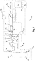
- system 10 can have two pumps, RT Pump 16 for supplying fluid flow to the retarder circuit and a transmission (TM) pump 14 for supplying fluid flow to the transmission.
- system 10 can have a single fluid pump for supplying fluid to the parallel fluid circuits.
- the single pump can be a larger capacity pump to provide flow and can be a two flow pump allowing the same or different flow rates.
- the pumps 14 and 16 can be volumetric type pumps and can have the same or similar nominal flow rate.
- System 10 can use a variety of fluids to supply lubrication and torque converter and retarder functionality such as transmission fluid, hydraulic fluid or other acceptable fluid or oil.
- the transmission circuit can include the TM pump 14 that provides fluid flow to the main regulating valve 18 at an appropriate fluid flow pressure to operate the clutches and the retarder (RT) 27 via the RT pilot valves 34 and 28.
- the transmission circuit fluid may flow from the sump 12 to main the regulating valve 18 to the torque convertor 22, to a cooler flow valve 30, to the transmission lubrication channels 21 and to the sump 12.
- the retarder circuit can include RT pump 16, RT on/off valve 24, breather check valve 26, RT 27, RT proportional valve 29, the cooler flow valve 30 and the sump 12.
- the cooler flow valve 30 can receive fluid flow from both the retarder circuit and the transmission circuit and may direct flow to the cooler 32 depending on the cooling needs of the system 10.
- the cooler flow valve 30 may direct flow from the torque convertor 22 in the transmission circuit to the cooler 32 and then to the transmission lubrication channels 21 and back to the sump 12, as shown in Fig. 1 .
- the two RT pilot pressure valves 34 and 28 can be part of the transmission valve control 20.
- One of the two RT pilot pressure valves 34, 28, namely RT pilot on/off valve 34 can control the state or the position of the RT on/off valve 24 to activate or deactivate the RT 27, and the other pilot pressure valve, namely RT pilot proportional valve 28, can control the state or position of the RT proportional valve 29 to regulate pressure on the RT out connection.
- the control of the valves 24 and 29 can be accomplished directly by solenoids controlled by the ECU, without the use of pilot pressure valves 34 and 28.
- the RT on/off valve 24 can be in the off position by the action of a spring force. RT on/off valve 24 remains in the off position until a solenoid or other force urges the RT on/off valve 24 to the on position against the spring force.
- the spring force may return RT on/off valve 24 to the off position once the vehicle is powered off.
- the RT on/off valve 24 may be returned to the off position manually the operator or automatically by an automated system.
- RT on/off valve 24 directs fluid flow from RT pump 16 directly into the sump 12. A part of the flow may be directed through a mist valve, for example.
- a mist valve for example.
- the backing pressure is low to minimize the drag loss although sufficient backing pressure may be applied for feeding a mist valve.
- RT pump 16 providing fluid flow from sump 12 through RT on/off valve 24 and back to the sump, switching the RT on/off valve 24 to the on position either through manual or automated system, fluid flow is directed to retarder 27 through a RT inlet 27a, and filling the retarder cavity.
- the fluid in the retarder cavity causes a toroidal oil flow, acting against movable blades or vanes which are part of or connected to a transmission shaft causing braking action or brake torque.
- a breather check valve 26 may be provided to prevent any leakage of the filling flow.
- the RT on/off valve 24 may be configured to be controlled by moving a valve spool of the RT on/off valve 24 through action of the RT pilot on/off valve 34.
- Deactivating RT 27 by moving the RT on/off valve 24 to the off position after operation of RT 27 can potentially cause the RT 27 to empty due to the rotor centrifugal force.
- the rotation of the bladed or vaned rotor in the retarder chamber may act as a turbo pump pumping the remaining fluid in the retarder cavity and/or in the RT circuit between the RT on/off valve 24 and the RT 27 to the sump 12.
- a breather 26 in the inlet line can be used to fill the RT 27 with air during emptying.
- the RT proportional valve 29 and the cooler flow valve 30 can be in a position connecting the RT outlet 27b with the sump 12 without any throttling for quick emptying.
- a retarder mist valve may be provided to provide oil mist to cool down and slow down the air stream in the retarder cavity to reduce the air drag of an empty retarder.
- the degree of brake torque applied to transmission shaft can be set to follow a certain brake torque curve also referred to as retarder capacity.
- the brake torque curve can be controlled by the operator as opposed to a non-controllable retarder or to an on/off retarder in which the degree of brake torque provided by the retarder follows a fixed brake curve depending on vehicle and/or driveshaft speed, among other possible less important factors.
- the degree of brake torque can be set by the operator adjusting a setting of an electronic control unit (ECU) 38.
- the ECU 38 is preferably in communication with a vehicle CAN BUS and/or man machine interface and/or multi media interface.
- the degree of brake torque or braking torque set by the vehicle operator can potentially also be overridden by a back-up automated system configured to prevent overheating or to correct or avoid unsafe situations.
- ECU can move RT pilot on/off valve 34 from the off position against the spring biasing force to the on position to cause fluid flow through the RT 27 to produce brake torque against the rotor or transmission shaft.
- the RT pilot on/off valve 34 can be switched on manually by the operator of the vehicle by a lever or a pedal or other means or using automated systems such as one sensing vehicle braking parameters, such as engagement of brakes, brake friction, overheating of the brakes and/or one sensing vehicle inclination and declines the vehicle encounters and/or one sensing the vehicle or engine speed or speed increase.
- the degree of brake torque meaning the wanted or desired brake profile/curve or retarder capacity, can be set by an operator via the same lever or pedal or other means. Additionally or alternatively, the degree of brake torque can be selected using a separate selector device.
- the ECU 38 may sense the lever or pedal position or selector to obtain the desired degree of brake torque and may obtain the vehicle speed or rotor speed from the vehicle sensors. The ECU 38 can then determine an RT outlet pressure set point that provides the desired degree of brake torque.
- the ECU 38 may include a processor and an algorithm stored on electronic storage or memory to calculate the RT outlet set point. Additionally or alterntively, the processor can look up the RT outlet pressure set point from brake curve profiles, tables or graphs stored in an electric memory or storage.
- Fig. 2 Examples of brake torque tables that illustrate the relationship between rotor speed (n-RT in RPM), brake torque (RT capacity in 10% increments) and RT outlet pressure (pressure values in table measured in bars) are shown in Fig. 2 .
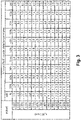
- An example of the effect of a possible long-term overheating protection on the outlet pressure set point is shown in Fig. 3 .
- those RT outlet pressure set point values which are reduced with respect to the corresponding RT outlet pressure set point values shown in Fig. 2 in order to prevent long-term overheating are marked with a letter "x".
- the value of the RT outlet pressure set point associated with a rotor speed of 2200 rpm and with a brake torque capacity of 90% is 10.0 bar.
- the corresponding value of the RT outlet pressure set point associated with a rotor speed of 2200 rpm and with a brake torque capacity of 90% is reduced to 6.9 bar.
- the ECU 38 can send the appropriate electrical current to the RT pilot proportional valve 28 which moves the respective solenoid that applies or releases fluid pressure to RT proportional valve 29.
- the RT proportional valve 29 position is changed based on this fluid pressure, applying the requested RT outlet pressure.
- the ECU 38 can send that appropriate electrical current to the RT pilot on/off valve 34 which moves the respective solenoid that applies fluid pressure to the RT on/off valve 24. As such the RT on/off valve 24 is pushed in lower position. This directs fluid flow to the RT inlet 27a, filling the retarder cavity and initiating the retarder braking action. Breather check valve 26 prevents any leakage of the filling flow.
- the ECU 38 may be configured or programmed to send electrical control signals directly to the RT on/off valve 24 equipped with a solenoid to move the valve position to and from an on and off position. It is understood that in the latter embodiment the RT on/off valve 24 comprises an electromagnetically activated valve instead rather than a fluid pressure controlled valve.
- the RT pilot proportional valve 28 adjusts the RT proportional valve 29 which is fluidly connected to the retarder outlet 27b.
- RT proportional valve 29 can adjust the throttling of the fluid exiting the retarder outlet to ensure the retarder outlet pressure stays within certain range of the pressure set point.
- the ECU 38 may be configured or programmed to control the RT proportional valve 29 by sending electrical signals directly to the RT proportional valve 29 equipped with a solenoid.
- a pressure sensor 36 may be provided to communicate the RT outlet pressure to the RT pilot proportional valve 28 or to the ECU 38. It is understood that in the latter embodiment the RT proportional valve 29 comprises an electrically controlled valve rather than a fluid pressure controlled valve.
- the RT proportional valve 29 may be configured such that fluid from the RT proportional valve 29 can be directed selectively either to the sump 12 or to the cooler 32 via the cooler flow valve 30, for example depending on the RT outlet pressure.
- the cooler flow valve 30 may be biased to a valve position directing flow to the sump 12, for instance by means of a spring, until the bias force is overcome to move a valve spool of the cooler flow valve 30 to direct flow to the cooler 32 and only subsequently to the sump 12.
- a valve spool of the RT proportional valve 29 is moved to direct flow to the cooler 32 and only subsequently to the sump 12.
- the cooler flow valve 30 directs the fluid flow from the transmission circuit directly to the transmission lubrication channels 21 and to the sump 12 without passing the cooler 12. It is conceivable that the predetermined pressure determining the position of the cooler flow valve 30 can be adjusted by changing the spring, which could be required in case of very high cooler pressure loss.
- the pressure at the RT outlet 27b may determine the position of the cooler flow valve 30.
- the cooler flow valve 30 may include a hydraulic actuator in fluid communication or in selective fluid communication with the RT outlet 27b.
- the cooler flow valve 30 position is directly controlled by a solenoid, receiving electrical current from the ECU 38.
- ECU 38 sends an electrical current based on the RT outlet pressure set point or based on a sensor measuring the RT outlet pressure or based on other means.
- Flow from RT proportional valve 29 can flow to cooler flow valve 30 which can receive flow from both the retarder and transmission circuits.
- the flow to the cooler flow valve 30 coming from the transmission circuit, in particular from the torque converter 22, may be directed to the cooler 32 whereas the retarder circuit flow may be directed to bypass the cooler 32.
- the RT outlet pressure typically may not be sufficiently high to overcome the cooler pressure loss. Consequently, when the RT 27 is in use and when the RT outlet pressure is sufficiently high, the cooler flow valve 30 directs the flow from the retarder circuit to the cooler 32, and the transmission circuit flow is directed to bypass the cooler 32.
- the cooler flow valve 30 can be controlled by pressure sensors in or about the valve or the cooler flow valve 30 can be controlled by the ECU 38 and pressure sensors provided in the retarder circuit and communicating with the ECU 38. It is conceivable that the predetermined pressure determining flow to the cooler valve 30 can be adjusted by changing the spring of the cooler flow valve 30, which could be required in case of very high cooler pressure loss.
- the cooler 32 can be positioned in the circuit containing the largest heat source, as soon as the RT outlet pressure passes a certain cooler flow valve pressure threshold. Therefore, the hydrodynamic retarder system presently disclosed can accept cooler and tubing components with relatively high head losses, up to the cooler flow valve pressure threshold. These components can be switched without affecting the retarder control function.
- the cooler 32 and the fluid tubing can be selected according to desired preferences as long as the head loss is below the pressure threshold of the cooler flow valve 30.
- This pressure threshold may be determined by the spring of the cooler flow valve 30, for example. Even the threshold pressure could be increased as desired by changing the cooler flow valve spring, which could be required in case of very high cooler and tubing head losses. Nevertheless, this could lead to some discontinuities/steps in the brake torque curves and/or increased sump fluid temperature under some working conditions.
- controllable retarder system for transmissions as disclosed herein can provide short-term and long-term overheating protection that is cooler independent. Short term rapid overheating can occur when the RT 27 is engaged during high vehicle or rotor speed paired with high brake torque capacity and/or an already high RT outlet pressure. Such rapid overheating can lead to destruction of seals or other components.
- Short-term RT overheating can be prevented or substantially reduced by the ECU 38 and brake torque algorithm, table, curves or profiles by rejecting any calculated or obtained RT outlet pressure set points that could cause rapid overheating.
- the algorithm will calculate or the table will indicate using a high RT outlet pressure set point. But since this RT outlet pressure set point may result in rapid overheating, the ECU can be programmed to either apply a correction factor to lower the pressure set point or may disallow use of the set point if it exceeds certain values based on the conditions.
- RT overheating which can occur when the retarder has been used for an extended period of time and heat generation is higher than the cooler capacity, can be avoided or substantially reduced by the present systems.
- a correction factor on the RT outlet pressure set point that may otherwise be determined by ECU 38 based on the RT outlet temperature can be applied. Shaded areas on table shown in Fig. 3 illustrate reduced RT outlet pressures set points to prevent long-term overheating conditions.
- Temperature sensors also connected to ECU can cause ECU to apply a correction factor to reduce the outlet pressure set point from the outlet pressure set point determined by the algorithm, tables or curves to prevent long-term overheat from long-term retarder use.
- temperature sensor 36 can be included in the fluid flow exiting retarder fluid outlet or adjacent thereto to protect against overheating of the fluid.
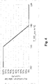
- the ECU 38 receives temperature data to adjust the retarder via control of RT outlet pressure according to Fig. 4 , which illustrates the degree or percentage reduction of the RT outlet pressure set point.
- the retarder outlet pressure can be multiplied by a correction factor from 1 to 0, in case the temperature at the retarder outlet changes from 160°C to 165°C. Temperatures below 160°C the correction factor can be 1 which means that there is no outlet pressure correction. As such, the retarder outlet temperature remains under 165C, at least in steady state condition.
Landscapes
- Engineering & Computer Science (AREA)
- Mechanical Engineering (AREA)
- Transportation (AREA)
- General Engineering & Computer Science (AREA)
- Physics & Mathematics (AREA)
- Fluid Mechanics (AREA)
- Chemical & Material Sciences (AREA)
- Combustion & Propulsion (AREA)
- Transmission Of Braking Force In Braking Systems (AREA)
Description
- The present disclosure primarily relates to vehicle braking assistance referred to as retarder systems and methods. In particular, the systems and methods relate to hydrodynamic retarders and more particularly to integrated hydrodynamic transmission and retarder systems. More specifically, the systems and methods disclosed herein are directed to integrated hydrodynamic transmission and proportionally controllable retarder systems.
- In hydrodynamic transmissions, in particular in hydrodynamic transmissions for automotive vehicles, a retarder can be connected to the transmission system, directly or indirectly to the transmission input or output shaft or any other transmission shaft to assist braking, for example of an automotive vehicle the transmission is incorporated in, by slowing the rotation of the transmission shaft. The retarder uses the friction and shock losses of the movable blades or vanes of a rotor connected to the transmission shaft and the fixed blades or vanes of a stator connected to a retarder frame. A chamber containing the blades can be fluid-filled or emptied. The toroidal fluid flow in the chamber acts against the blades of the rotor, slowing the rotation of the rotor and of the transmission shaft and generating vehicle braking. This slowing of the transmission shaft is especially helpful when the brakes are under heavy use during downhill driving. The movable blades can be attached to the transmission shaft or to a separate rotor that is connected to the transmission shaft directly or through a gear or gear box to slow the driveshaft further and assist the braking of the vehicle. Retarder systems can use standard transmission fluid (gear oil), engine oil, or a separate fluid, fluid mixtures, or oil.
-
CN 106402209 relates to an electro-hydraulic proportional control system for a liquid filling rate of a hydraulic retarder with feedback, which can realize the adjustment of the liquid filling rate in the wheel cavity of the retarder and thus the control of the hydraulic retarder. -
US 2016/244041 A1 relates to a hydrodynamic machine for producing a braking torque, the hydrodynamic machine comprising: a toroidal working chamber including a first bladed wheel and a second bladed wheel arranged concentrically with the first bladed wheel; and a hydraulic system including an open loop and closed loop control unit, a working medium accumulator, a line system, a pump operable to produce a volume flow circulation of a working medium through the line system and the toroidal working chamber, a heat exchanger, and a pressure control valve operable to control or adjust the baking performance or the braking torque. - When vehicle braking assistance or retardation is needed, fluid, typically the transmission fluid or oil is pumped into the retarder chamber, and the friction and shock losses of the blades or vanes connected to or part of the transmission shaft will slow the vehicle. ON/OFF retarders can either be filled or emptied. For proportionally controllable retarders, the degree of retardation can be varied in several ways including adjusting the fill level of the retarder chamber, the retarder inlet pressure, the retarder outlet pressure in the chamber, or an extension of the gap between the rotor and the stator.
- The friction and shock losses heat the fluid. Overheated fluid will degrade rapidly, reducing viscosity and performance and requiring a higher change interval frequency and reducing the life of the seals. To prevent overheating, the fluid can be circulated through a cooling system. The cooling system can be integrated in the engine cooling system of the vehicle, or a separate cooling system specific to the transmission and/or the retarder may be used. For instance, the cooling system may comprise an air-oil heat exchanger. After passing the cooling system, the cooled fluid may be returned to the oil or fluid sump before being re-circulated. Indeed, cooling of the transmission fluid may be needed even where a retarder is not utilized due to high demands placed on the transmission system such as in off-highway vehicles. In some integrated hydrodynamic transmission and retarder systems, especially in proportionally controlled hydrodynamic retarders, cooling of the working or transmission fluid is performed by a cooling system integrated in the engine cooling system of the vehicle, the cooling system containing an oil-engine coolant heat exchanger to dissipate the heat from the fluid or oil into the motor cooling circuit of the vehicle.
- Proportionally controlled hydrodynamic retarders are retarders that can provide a selectable, predetermined and/or variable brake torque or slowing force. Such proportionally controlled retarder systems can also have cooling systems that are independent or separate from the engine cooling system or that are integrated in the engine cooling. In certain known proportionally controlled retarders, a heat exchanger is used to dissipate the heat from the fluid into the motor cooling circuit of the vehicle. In order to save space and/or minimize costs, these known systems typically do not make use of a pump to circulate oil between the retarder and the cooler. Instead such systems typically use the retarder itself as a turbo pump to provide the pressure head to create flow through the retarder and the cooler. During activation of the retarder, a valve allows fluid to enter the retarder chamber while the air may be released, for example through a breather. The cooling flow rate is determined by the balance between the retarder pressure head and the head loss in the tubing or channels, valves and the heat exchanger. As a result, these components have narrow tolerances and cannot be easily changed without affecting the flow rate and consequently the cooling function. Indeed, in many cases, the limited ability to change components and thereby flow rates can be the reason for integrating a heat exchanger into the retarder system.
- In other known proportionally controlled hydrodynamic retarder systems, a relatively small pump can be used to provide the retarder filling flow. In case faster filling is required, an accumulator system can be added. Known proportionally controlled hydrodynamic retarders can typically be controlled in several ways.
-
U.S. Patent No. 3,987,874 discloses controlling the retarder inlet pressure to control the brake torque applied to the rotor, wherein a high inlet pressure typically results in a higher brake torque applied to the transmission. -
U.S. Patent No. 3,774,734 discloses control of retarder outlet pressure, wherein a higher outlet pressure typically results in a higher brake torque. -
U.S. Patent No. 5,771,997 discloses controlling the fill level in the retarder to control the brake torque, wherein a higher filling level typically results in a higher brake torque. -
U.S. Patent No. 4,864,872 discloses controlling an extension of a gap between the rotor and the stator, wherein reducing the extension of the gap typically results in a higher brake torque. - And
U.S. Patent No. 3,863,739 discloses brake torque relative to retarder properties and rotor speed. At a given retarder inlet pressure, the brake torque applied by the retarder increases with increasing rotor speed. - Hence, there is demand for a hydrodynamic retarder system including a hydrodynamic retarder that can be more flexibly integrated with different cooling systems and that preferably provides improved control of the brake torque applied via the hydrodynamic retarder, and for a corresponding method of operating said system.
- A hydrodynamic retarder system and method of operation capable of providing these functionalities are defined in the independent claims. Special embodiments are described in the dependent claims.
- Thus, a hydrodynamic retarder system is presently proposed, in particular a hydrodynamic retarder system for a transmission of an automotive vehicle. The proposed hydrodynamic retarder system includes:
- a hydrodynamic retarder (RT) comprising a rotor and a stator and having an inlet and an outlet;
- a retarder (RT) proportional valve in fluid communication with the retarder (RT) outlet, the RT proportional valve configured to control a RT outlet pressure; and
- an electronic control unit (ECU);
- wherein the ECU is configured to determine a retarder (RT) outlet pressure set point based on at least one of or both of a current rotor speed and a desired brake torque; and
- wherein the ECU is configured to control the RT proportional valve based on the RT outlet pressure set point such that the RT proportional valve provides a RT outlet pressure within a range or within a predetermined range of the RT outlet pressure set point.
- Furthermore, a method of controlling the hydrodynamic RT system is presently proposed, the method comprising the steps of:
- determining a RT outlet pressure set point based on at least one of or both of a current speed of a rotor of the hydrodynamic RT and a desired brake torque; and
- controlling the RT proportional valve based on the RT outlet pressure set point such that the RT proportional valve provides a RT outlet pressure within a range of the RT outlet pressure set point.
- The presently proposed system and method can address issues of interchangeability of the cooling system, the variability of braking torque curves applied by the RT, overheating and other issues not previously considered. In particular, hydrodynamic transmissions including the presently proposed hydrodynamic RT system can potentially provide a selectable braking torque function and keep a high freedom in transmission cooling system choice.
- The ECU may be configured or programmed to determine the RT outlet pressure set point based on the current rotor speed and based on the desired brake torque.
- The hydrodynamic RT system may further comprise a table stored in the ECU. For example, the ECU may include a memory device for storing the table. The memory device may include an electronically readable device, a magnetically readable device or an optically readable device, for example. The table may comprise one or more rotor speed values. Additionally or alternatively, the table may comprise one or more desired brake torque values. The table may provide the RT outlet pressure set point as a function of at least one of or both of the one or more rotor speed values, and the one or more desired brake torque values.
- In other words, the table may include brake torque curves showing the relationship between vehicle or rotor/transmission shaft speed, the retarder outlet pressure and the brake torque applied by the retarder. This relationship can be formulated into an algorithm, a brake torque table, curve or profile. These can be formulated for specific configurations of the vehicle depending on factors such as retarder size and blades or vane shapes, vehicle weight, overall driveline drag, typical descent values and other parameters. The algorithms, tables or brake torque curves or profiles which can indicate the degree of brake torque relative to rotor speed and/or vehicle speed and retarder outlet pressure can be used by electronic controls in the vehicle to provide a proportionally controllable retarder.
- The operator or driver of the vehicle the hydrodynamic RT system may be incorporated in usually cannot accurately judge or determine the degree of brake torque that will be applied by the RT based on the RT outlet pressure and/or based on the speed of the vehicle. Specifically, the brake torque applied by the RT typically increases with increasing rotor speed thereby following a characteristic curve, wherein each point on this curve may require or represent a certain minimal outlet pressure which may also increase with increasing rotor speed. As such, for a certain RT outlet pressure the brake torque usually follows a characteristic curve for increasing rotor speeds up to the rotor speed for which the requested minimal outlet pressure equals the applied outlet pressure, and from this point on the brake torque applied by the RT normally remains about constant for further increasing rotor speeds. As disclosed herein, the ability to shift between a series of prescribed or stored braking torque curves, wherein each curve may include a brake torque which strictly increases with increasing rotor speed, can improve the drivability of the vehicle and improve safety as compared to control strategies which include directly controlling the RT outlet pressure without taking into account other variables such as rotor speed. In addition, a combination of high RT outlet pressure and a high RT capacity / high brake torque setting can result in rapid overheating of the retarder fluid. The table stored in the ECU may include brake torque curves which are designed to avoid such combinations.
- The ECU may be configured or programmed to control or regulate the RT outlet pressure via the RT proportional valve using feedback control, for example.
- The hydrodynamic RT system may further comprise an input device, in particular an input device in communication with the ECU. The input device may comprise but is not limited to at least one of or each of a pedal, a lever, a knob, a switch, a joystick, a touch screen, a microphone or a camera, for example. The ECU may be configured or programmed to determine the desired brake torque based on or further based on an input signal provided by an operator via the input device. For example, the operator may select a certain brake torque setting such as a desired brake torque value which may include a desired percentage of a maximum applicable brake torque or a desired brake torque curve.
- The hydrodynamic RT system may further comprise one or more vehicle sensors in communication with the ECU. The ECU may then be configured to determine the outlet pressure set point based on or further based on one or more vehicle sensor signals provided by the one or more vehicle sensors.
- The one or more vehicle sensors may include but are not limited to at least one of or each of a temperature sensor for measuring an RT fluid temperature, for example for measuring an RT fluid temperature at the RT outlet, within an RT chamber, within a cooler, within one or more transmission cooling channels, or within a fluid sump; a pressure sensor for measuring an RT fluid pressure, in particular for measuring an RT fluid pressure at the RT outlet; an inclination sensor for measuring an inclination angle, in particular an inclination angle of the RT, of the transmission the hydrodynamic RT system may be coupled to, or of the vehicle the hydrodynamic RT system may be incorporated in; and a speed sensor, in particular for measuring a speed of the RT rotor, a speed of a transmission shaft, or a speed of the vehicle the hydrodynamic RT system may be incorporated in.
- The hydrodynamic RT system may comprise at least one of or each of a fluid sump, a cooler and at least one cooler flow valve. The at least one cooler flow valve may be configured to selectively fluidly connect the RT proportional valve with either one of the cooler and the fluid sump. For example, the at least one cooler flow valve may have a first control position and a second control position. The at least one cooler flow valve may be configured such that when it is switched to the first control position it directs fluid from the RT proportional valve to the fluid sump, for example in such a way that the fluid from the RT proportional valve bypasses the cooler. And the at least one cooler flow valve may be configured such that when it is switched to the second control position it directs fluid from the RT proportional valve to the cooler. After passing the cooler, the fluid may then be directed from the cooler to the sump, for example.
- The at least one cooler flow valve may be biased to the first control position, for example by a biasing member which may include an elastic biasing member such as a spring. For instance, the at least one cooler flow valve may be configured such that if the RT outlet pressure is above a first pressure threshold, the at least one cooler flow valve is switched to the second control position fluidly connecting the RT proportional valve with the cooler. And the at least one cooler flow valve may be configured such that if the RT outlet pressure is below a second pressure threshold equal to or smaller than the first pressure threshold, the at least one cooler flow valve fluidly is switched to the first control position connecting the RT proportional valve with the fluid sump.
- For example, the at least one cooler flow valve may comprises at least one hydraulic actuator in fluid communication with the RT outlet. The hydraulic actuator may then be configured to control a control position of the at least one cooler flow valve based on the RT outlet pressure. For instance, the hydraulic actuator of the cooler flow valve may apply a RT outlet pressure to a valve spool of the cooler flow valve and may bias the cooler flow valve toward the second control position of the cooler flow valve. For example, the outlet pressure applied to the cooler flow valve via the hydraulic actuator of the cooler flow valve may act against the above-described biasing member of the cooler flow valve biasing the cooler flow valve toward the first control position. Additionally or alternatively, the at least one cooler flow valve may comprise a solenoid in communication with the ECU wherein the solenoid is configured to control a control position of the at least one cooler flow valve based on electromagnetic signals received from the ECU. For example, the ECU may be in communication with a pressure sensor for measuring a RT outlet pressure and may control a control position of the cooler flow valve via the solenoid of the cooler flow valve based on a RT outlet pressure measured or sensed using the pressure sensor.
- The hydrodynamic RT system may further comprise a torque converter and/or one or more transmission lubrication channels. The torque converter may be in fluid communication with the fluid sump, for example via a transmission pump. And the one or more transmission lubrication channels may be in fluid communication with the fluid sump. The at least one cooler flow valve may be configured to selectively fluidly connect the torque converter with either one of the cooler and the one or more transmission lubrication channels. For example, the at least one cooler flow valve may be configured such that when it is switched to the first control position it directs fluid from the torque converter to the cooler. From the cooler the fluid may then further be directed to the one or more transmission lubrication channels. And from the one or more transmission lubrication channels the fluid may then further be directed to the fluid sump. And the at least one cooler flow valve may be configured such that when it is switched to the second control position it directs fluid from the torque converter to the one or more transmission lubrication channels, for example such that the fluid from the torque converter bypasses the cooler.
- The at least one cooler flow valve may be configured such that if the RT outlet pressure is above the first pressure threshold, the at least one cooler flow valve fluidly connects the torque converter with the one or more fluid lubrication channels such that fluid from the torque converter bypasses the cooler. And the at least one cooler flow valve may be configured such that if the RT outlet pressure is below the second pressure threshold equal to or smaller than the first pressure threshold, the at least one cooler flow valve fluidly connects the torque converter with the cooler.
- The RT proportional valve may comprise a first hydraulic actuator. The first hydraulic actuator of the RT proportional valve may bias the RT proportional valve toward a closed position in which the RT proportional valve increases a RT outlet pressure. The first hydraulic actuator of the RT proportional valve may be fluidly connected with a first pilot valve. The first pilot valve may selectively fluidly connect the first hydraulic actuator of the RT proportional valve with the fluid sump, for example via one of a RT pump or the above-mentioned transmission pump. That is, a control position of the first pilot valve may control or regulate a hydraulic force applied to a valve spool of the RT proportional valve via the first hydraulic actuator of the RT proportional valve. The first pilot valve may include a solenoid in communication with the ECU and configured to control a control position of the first pilot valve based on electromagnetic signals received from the ECU. For example, the ECU may be in communication with a pressure sensor for measuring a RT outlet pressure and may be configured to control a control position of the first pilot valve based on the measured RT outlet pressure.
- The RT proportional valve may further comprise a second hydraulic actuator. The second hydraulic actuator of the RT proportional valve may bias the RT proportional valve toward an open position in which the RT proportional valve reduces a RT outlet pressure. The second hydraulic actuator of the RT proportional valve may be fluidly connected or selectively fluidly connected with the RT outlet. That is, the RT proportional valve may be configured such that the RT outlet pressure biases the RT proportional valve toward the open position in which the RT proportional valve reduces the RT outlet pressure.
- Additionally or alternatively, the RT proportional valve may be electrically controlled. For example, the RT proportional valve may comprise a solenoid in communication with the ECU and configured to control a control position of the RT proportional valve based on electromagnetic signals received from the ECU. For example, the ECU may be in communication with a pressure sensor for measuring a RT outlet pressure and may be configured to control a control position of the RT proportional valve based on the measured RT outlet pressure.
- The RT proportional valve may further comprise a biasing member, in particular an elastic biasing member such as a spring. The biasing member of the RT proportional valve may be configured to bias the RT proportional valve toward the open position.
- The hydrodynamic RT system may further comprise a fluid sump, a RT pump in fluid communication with the fluid sump, and a RT on/off valve configured to selectively fluidly connect the RT pump with the RT inlet for selectively filling the hydrodynamic RT.
- The RT on/off valve may comprise a first hydraulic actuator. The first hydraulic actuator of the RT on/off valve may bias the RT on/off valve toward an open position in which the RT on/off valve fluidly connects the RT inlet with the RT pump so that the RT pump may fill the hydrodynamic RT. The first hydraulic actuator of the RT on/off valve may be selectively fluidly connected with a fluid pump such as with the above-described transmission pump via a second pilot valve. The second pilot valve may include a solenoid in communication with the ECU and configured to control a control position of the second pilot valve based on electromagnetic signals received from the ECU. For example, the ECU may be configured or programmed to fluidly connect the first hydraulic actuator of the RT on/off valve with the fluid pump to switch the RT on/off valve to the open position and to fill the hydrodynamic RT based on an input command provided by an operator, or based sensor signals provided by one or more vehicle sensors.
- The RT on/off valve may further comprise a second hydraulic actuator. The second hydraulic actuator of the RT on/off valve may bias the RT on/off valve toward a closed position in which the RT on/off valve fluidly isolates the RT inlet from the RT pump so that the RT pump may not fill the hydrodynamic RT. The second hydraulic actuator of the RT on/off valve may be fluidly connected or selectively fluidly connected with the RT inlet.
- Additionally or alternatively, the RT on/off valve may be electrically controlled. For example, the RT on/off valve may comprise a solenoid in communication with the ECU and configured to control a control position of the RT on/off valve based on an electromagnetic signal received from the ECU. For example, the ECU may be configured or programmed to control a control position of the RT on/off valve based on an input command provided by an operator, or based sensor signals provided by one or more vehicle sensors.
- The RT on/off valve may further comprise a biasing member, in particular an elastic biasing member such as a spring. The biasing member of the RT on/off valve may be configured to bias the RT on/off valve toward the closed position in which the RT on/off valve fluidly isolates the RT inlet from the RT pump so that the RT pump may not fill the hydrodynamic RT.
- The ECU may be configured or programmed to control a brake torque by adjusting the RT outlet pressure. For example, the ECU may be configured or programmed to use an algorithm to calculate or tables or brake torque curves or profiles to look up the functional relationships between retarder RT outlet pressure, vehicle or rotor speed, and brake torque curve selected by the operator to provide the selected RT outlet pressure within certain limits. The ECU may also be configured to make adjustments to the RT outlet pressure to address short term and long term RT overheating protection independent of whether or not fluid from the RT is directed to a cooling system.
- The ECU may be configured or programmed such that an operator can select a brake torque curve which gives a particular degree or capacity of brake torque such as between 0% or other minimum setting such as 25% and 100% or other maximum such as 90%. The minimum setting may be represented by a minimum brake torque curve and the maximum setting may be represented by a maximum brake torque curve, a variation of the brake capacity may provide a linear or other interpolation between those curves. The ECU may then be configured to select the appropriate RT outlet pressure for the current rotor speed to reach a selected brake torque curve using an algorithm, table or other brake curve / capacity profile. For example, the ECU may be configured or programmed to include a processor connected to an electric memory storing an algorithm, table or brake curve or profile to calculate or obtain an RT outlet pressure set point according to the brake torque curve selected by the operator and vehicle or rotor speed. As such, the ECU may be configured or programmed to communicate an RT outlet pressure set point obtained directly or indirectly to the RT proportional valve that can adjust the RT outlet pressure required to provide the selected brake torque.
- In addition, unexpected high brake torque and rapid overheating can be greatly reduced or prevented because the controllable or proportional RT system disclosed herein can be configured to be set, controlled and/or adjusted accordingly. In other words, the ECU may be configured or programmed to adjust or disallow the selecting of a brake torque curve that could result in extremely high brake torque under certain vehicle operating conditions such as high rotor speeds and high RT outlet pressure. For instance, the ECU may be configured or programmed to avoid selecting an RT outlet pressure set point that could lead to rapid overheating of the hydrodynamic RT system. In other words, at high rotor speeds and high RT outlet pressure, the ECU may be configured to adjust the RT outlet pressure to prevent a high brake torque selected by the operator from causing extremely high brake torque and rapid overheating. For example, a high brake torque setting selected by the operator would normally result in the ECU calculating or obtaining a high RT outlet pressure set point under low to moderate rotor speed and/or RT outlet pressure conditions because overheating under such conditions would not occur. But under high rotor speed and/or RT outlet pressure the ECU can be programmed to adjust or disallow an RT outlet pressure set point that could lead to rapid overheating. For example, RT outlet pressure set points that could result in rapid overheating can be programmed in the algorithm or identified in the brake torque table, curve or profile.
- It is understood however that after long term use of the RT even using an appropriate brake curve or brake torque setting could possibly still result in overheating of the RT fluid beyond the cooler capacity, which can in time also lead to RT overheating referred to as long-term overheating. The presently proposed hydraulic RT system may be configured to address such long-term heating by further applying an overheating correction factor to the RT outlet pressure set point. For example, the ECU can be connected to one or more temperature sensors measuring the temperature of the fluid or can account for time of active operation of the retarder to estimate long-term overheating, and can adjust the RT outlet pressure set point.
- The hydraulic RT system may comprise a temperature sensor in/at the retarder outlet fluid flow, and the ECU may be configured or programmed to apply a correction factor to the RT outlet pressure set point based on the measured temperature, for example using an algorithm, a brake torque table or a brake torque curve. The correction factor can be stored in a lookup table or calculated by the processor using a correction factor formula to adjust the RT outlet pressure set point. The ECU may be configured or programmed to communicate with the RT proportional valve regulating the RT outlet pressure. Additionally or alternatively, the ECU may be configured or programmed to lower the outlet pressure set point based on temperature values measured with other temperature sensors, such a sump or a torque converter outlet temperature sensor.
- These and further advantages of the presently disclosed system and method are described in the following detailed description and are depicted in the accompanying drawing in which:
- Fig. 1
- shows a schematic view of one embodiment of a cooler independent hydrodynamic transmission and retarder system;
- Fig. 2
- shows a table of retarder outlet pressure set points in bars given retarder braking capacity in percentage terms (horizontal axis) at given rotor speeds (vertical axis);
- Fig. 3
- shows a table of retarder outlet pressure set points in bars affected by correction factors preventing long-term overheating for a certain cooling system given retarder braking capacity in percentage terms (horizontal axis) at given rotor speeds (vertical axis); and
- Fig. 4
- shows a graph of retarder capacity correction factor based on measurement of the temperature RT outlet.
- It is to be understood that the invention may assume various alternative components, orientations and configurations, except where expressly specified to the contrary. It is also understood that the specific devices and processes illustrated in the attached drawings, and described in the specification are merely exemplary embodiments of the inventive concepts disclosed and defined herein. Therefore, specific dimensions, directions or other physical characteristics relating to the various embodiments disclosed herein are not to be considered as limiting, unless expressly stated otherwise.
- One embodiment of a hydrodynamic transmission having a controllable or
proportional retarder system 10 is shown inFig. 1 . In this embodiment,system 10 can have two pumps,RT Pump 16 for supplying fluid flow to the retarder circuit and a transmission (TM) pump 14 for supplying fluid flow to the transmission. In anotherembodiment system 10 can have a single fluid pump for supplying fluid to the parallel fluid circuits. In such a system, the single pump can be a larger capacity pump to provide flow and can be a two flow pump allowing the same or different flow rates. For example, thepumps System 10 can use a variety of fluids to supply lubrication and torque converter and retarder functionality such as transmission fluid, hydraulic fluid or other acceptable fluid or oil. - The transmission circuit can include the
TM pump 14 that provides fluid flow to the main regulatingvalve 18 at an appropriate fluid flow pressure to operate the clutches and the retarder (RT) 27 via theRT pilot valves sump 12 to main the regulatingvalve 18 to thetorque convertor 22, to acooler flow valve 30, to thetransmission lubrication channels 21 and to thesump 12. - The retarder circuit can include
RT pump 16, RT on/offvalve 24,breather check valve 26,RT 27, RTproportional valve 29, thecooler flow valve 30 and thesump 12. - In the embodiment shown in
Fig. 1 , thecooler flow valve 30 can receive fluid flow from both the retarder circuit and the transmission circuit and may direct flow to the cooler 32 depending on the cooling needs of thesystem 10. When theRT 27 is not in use or when the RT outlet pressure indicates low pressure and thereby low heat levels, thecooler flow valve 30 may direct flow from thetorque convertor 22 in the transmission circuit to the cooler 32 and then to thetransmission lubrication channels 21 and back to thesump 12, as shown inFig. 1 . - The two RT
pilot pressure valves transmission valve control 20. One of the two RTpilot pressure valves valve 34, can control the state or the position of the RT on/offvalve 24 to activate or deactivate theRT 27, and the other pilot pressure valve, namely RT pilotproportional valve 28, can control the state or position of the RTproportional valve 29 to regulate pressure on the RT out connection. In alternative embodiments, the control of thevalves pilot pressure valves - When the vehicle is powered off, the RT on/off
valve 24 can be in the off position by the action of a spring force. RT on/offvalve 24 remains in the off position until a solenoid or other force urges the RT on/offvalve 24 to the on position against the spring force. The spring force may return RT on/offvalve 24 to the off position once the vehicle is powered off. Alternatively, the RT on/offvalve 24 may be returned to the off position manually the operator or automatically by an automated system. In the off position, RT on/offvalve 24 directs fluid flow fromRT pump 16 directly into thesump 12. A part of the flow may be directed through a mist valve, for example. In the embodiment of thesystem 10 depicted inFig. 1 the backing pressure is low to minimize the drag loss although sufficient backing pressure may be applied for feeding a mist valve. From this state, withRT pump 16 providing fluid flow fromsump 12 through RT on/offvalve 24 and back to the sump, switching the RT on/offvalve 24 to the on position either through manual or automated system, fluid flow is directed to retarder 27 through a RT inlet 27a, and filling the retarder cavity. The fluid in the retarder cavity causes a toroidal oil flow, acting against movable blades or vanes which are part of or connected to a transmission shaft causing braking action or brake torque. Abreather check valve 26 may be provided to prevent any leakage of the filling flow. The RT on/offvalve 24 may be configured to be controlled by moving a valve spool of the RT on/offvalve 24 through action of the RT pilot on/offvalve 34. - Deactivating
RT 27 by moving the RT on/offvalve 24 to the off position after operation ofRT 27 can potentially cause theRT 27 to empty due to the rotor centrifugal force. The rotation of the bladed or vaned rotor in the retarder chamber may act as a turbo pump pumping the remaining fluid in the retarder cavity and/or in the RT circuit between the RT on/offvalve 24 and theRT 27 to thesump 12. Abreather 26 in the inlet line can be used to fill theRT 27 with air during emptying. The RTproportional valve 29 and thecooler flow valve 30 can be in a position connecting theRT outlet 27b with thesump 12 without any throttling for quick emptying. A retarder mist valve may be provided to provide oil mist to cool down and slow down the air stream in the retarder cavity to reduce the air drag of an empty retarder. - The degree of brake torque applied to transmission shaft can be set to follow a certain brake torque curve also referred to as retarder capacity. The brake torque curve can be controlled by the operator as opposed to a non-controllable retarder or to an on/off retarder in which the degree of brake torque provided by the retarder follows a fixed brake curve depending on vehicle and/or driveshaft speed, among other possible less important factors. The degree of brake torque can be set by the operator adjusting a setting of an electronic control unit (ECU) 38. The
ECU 38 is preferably in communication with a vehicle CAN BUS and/or man machine interface and/or multi media interface. The degree of brake torque or braking torque set by the vehicle operator can potentially also be overridden by a back-up automated system configured to prevent overheating or to correct or avoid unsafe situations. - In order to activate functioning of
RT 27 to provide brake torque, ECU can move RT pilot on/offvalve 34 from the off position against the spring biasing force to the on position to cause fluid flow through theRT 27 to produce brake torque against the rotor or transmission shaft. The RT pilot on/offvalve 34 can be switched on manually by the operator of the vehicle by a lever or a pedal or other means or using automated systems such as one sensing vehicle braking parameters, such as engagement of brakes, brake friction, overheating of the brakes and/or one sensing vehicle inclination and declines the vehicle encounters and/or one sensing the vehicle or engine speed or speed increase. - The degree of brake torque, meaning the wanted or desired brake profile/curve or retarder capacity, can be set by an operator via the same lever or pedal or other means. Additionally or alternatively, the degree of brake torque can be selected using a separate selector device. Upon activation of the
RT 27 theECU 38 may sense the lever or pedal position or selector to obtain the desired degree of brake torque and may obtain the vehicle speed or rotor speed from the vehicle sensors. TheECU 38 can then determine an RT outlet pressure set point that provides the desired degree of brake torque. For example, theECU 38 may include a processor and an algorithm stored on electronic storage or memory to calculate the RT outlet set point. Additionally or alterntively, the processor can look up the RT outlet pressure set point from brake curve profiles, tables or graphs stored in an electric memory or storage. - Examples of brake torque tables that illustrate the relationship between rotor speed (n-RT in RPM), brake torque (RT capacity in 10% increments) and RT outlet pressure (pressure values in table measured in bars) are shown in
Fig. 2 . An example of the effect of a possible long-term overheating protection on the outlet pressure set point is shown inFig. 3 . InFig. 3 those RT outlet pressure set point values which are reduced with respect to the corresponding RT outlet pressure set point values shown inFig. 2 in order to prevent long-term overheating are marked with a letter "x". For example, in the table depicted inFig. 2 the value of the RT outlet pressure set point associated with a rotor speed of 2200 rpm and with a brake torque capacity of 90% is 10.0 bar. By contrast, in the table depicted inFig. 3 the corresponding value of the RT outlet pressure set point associated with a rotor speed of 2200 rpm and with a brake torque capacity of 90% is reduced to 6.9 bar. - Once
ECU 38 has determined the RT outlet pressure set point, theECU 38 can send the appropriate electrical current to the RT pilotproportional valve 28 which moves the respective solenoid that applies or releases fluid pressure to RTproportional valve 29. The RTproportional valve 29 position is changed based on this fluid pressure, applying the requested RT outlet pressure. - Once
ECU 38 senses the retarder activation signal and calculated or obtained the brake torque setting and vehicle or rotor speed, theECU 38 can send that appropriate electrical current to the RT pilot on/offvalve 34 which moves the respective solenoid that applies fluid pressure to the RT on/offvalve 24. As such the RT on/offvalve 24 is pushed in lower position. This directs fluid flow to the RT inlet 27a, filling the retarder cavity and initiating the retarder braking action.Breather check valve 26 prevents any leakage of the filling flow. In alternative embodiments, theECU 38 may be configured or programmed to send electrical control signals directly to the RT on/offvalve 24 equipped with a solenoid to move the valve position to and from an on and off position. It is understood that in the latter embodiment the RT on/offvalve 24 comprises an electromagnetically activated valve instead rather than a fluid pressure controlled valve. - The RT pilot
proportional valve 28 adjusts the RTproportional valve 29 which is fluidly connected to theretarder outlet 27b. RTproportional valve 29 can adjust the throttling of the fluid exiting the retarder outlet to ensure the retarder outlet pressure stays within certain range of the pressure set point. In alternative embodiments theECU 38 may be configured or programmed to control the RTproportional valve 29 by sending electrical signals directly to the RTproportional valve 29 equipped with a solenoid. For example, apressure sensor 36 may be provided to communicate the RT outlet pressure to the RT pilotproportional valve 28 or to theECU 38. It is understood that in the latter embodiment the RTproportional valve 29 comprises an electrically controlled valve rather than a fluid pressure controlled valve. - The RT
proportional valve 29 may be configured such that fluid from the RTproportional valve 29 can be directed selectively either to thesump 12 or to the cooler 32 via thecooler flow valve 30, for example depending on the RT outlet pressure. For example, thecooler flow valve 30 may be biased to a valve position directing flow to thesump 12, for instance by means of a spring, until the bias force is overcome to move a valve spool of thecooler flow valve 30 to direct flow to the cooler 32 and only subsequently to thesump 12. In the embodiment of thesystem 10 depicted inFig. 1 when the RT outlet pressure exceeds a pressure from about 1.5 bar to about 5.5 bar, preferably from about 2 bar to about 3 bar, a valve spool of the RTproportional valve 29 is moved to direct flow to the cooler 32 and only subsequently to thesump 12. In this position, thecooler flow valve 30 directs the fluid flow from the transmission circuit directly to thetransmission lubrication channels 21 and to thesump 12 without passing the cooler 12. It is conceivable that the predetermined pressure determining the position of thecooler flow valve 30 can be adjusted by changing the spring, which could be required in case of very high cooler pressure loss. - The pressure at the
RT outlet 27b may determine the position of thecooler flow valve 30. For example, thecooler flow valve 30 may include a hydraulic actuator in fluid communication or in selective fluid communication with theRT outlet 27b. In another embodiment, thecooler flow valve 30 position is directly controlled by a solenoid, receiving electrical current from theECU 38.ECU 38 sends an electrical current based on the RT outlet pressure set point or based on a sensor measuring the RT outlet pressure or based on other means. - Flow from RT
proportional valve 29 can flow tocooler flow valve 30 which can receive flow from both the retarder and transmission circuits. As described above, when theRT 27 is not in use or in use without a sufficiently high RT outlet pressure, the flow to thecooler flow valve 30 coming from the transmission circuit, in particular from thetorque converter 22, may be directed to the cooler 32 whereas the retarder circuit flow may be directed to bypass the cooler 32. While it may be preferable to direct the retarder circuit flow to the cooler 32 as soon as theRT 27 is activated, the RT outlet pressure typically may not be sufficiently high to overcome the cooler pressure loss. Consequently, when theRT 27 is in use and when the RT outlet pressure is sufficiently high, thecooler flow valve 30 directs the flow from the retarder circuit to the cooler 32, and the transmission circuit flow is directed to bypass the cooler 32. - The
cooler flow valve 30 can be controlled by pressure sensors in or about the valve or thecooler flow valve 30 can be controlled by theECU 38 and pressure sensors provided in the retarder circuit and communicating with theECU 38. It is conceivable that the predetermined pressure determining flow to thecooler valve 30 can be adjusted by changing the spring of thecooler flow valve 30, which could be required in case of very high cooler pressure loss. - Switching the cooler from the TM circuit to the RT circuit is possible without large pressure gradients in case the flow rate in both the TM circuit and the RT circuit are similar or about the same. Consequently, the cooler 32 can be positioned in the circuit containing the largest heat source, as soon as the RT outlet pressure passes a certain cooler flow valve pressure threshold. Therefore, the hydrodynamic retarder system presently disclosed can accept cooler and tubing components with relatively high head losses, up to the cooler flow valve pressure threshold. These components can be switched without affecting the retarder control function. In the
system 10 depicted inFig. 1 for example, the cooler 32 and the fluid tubing can be selected according to desired preferences as long as the head loss is below the pressure threshold of thecooler flow valve 30. This pressure threshold may be determined by the spring of thecooler flow valve 30, for example. Even the threshold pressure could be increased as desired by changing the cooler flow valve spring, which could be required in case of very high cooler and tubing head losses. Nevertheless, this could lead to some discontinuities/steps in the brake torque curves and/or increased sump fluid temperature under some working conditions. - The presently disclosed system may be configured to control overheating in the system regardless of the cooler functionality. In particular, controllable retarder system for transmissions as disclosed herein can provide short-term and long-term overheating protection that is cooler independent. Short term rapid overheating can occur when the
RT 27 is engaged during high vehicle or rotor speed paired with high brake torque capacity and/or an already high RT outlet pressure. Such rapid overheating can lead to destruction of seals or other components. - Short-term RT overheating can be prevented or substantially reduced by the
ECU 38 and brake torque algorithm, table, curves or profiles by rejecting any calculated or obtained RT outlet pressure set points that could cause rapid overheating. For example, when an operator selects a high brake torque setting and theretarder 27 is activated while the vehicle or rotor is travelling or rotating at a high speed, the algorithm will calculate or the table will indicate using a high RT outlet pressure set point. But since this RT outlet pressure set point may result in rapid overheating, the ECU can be programmed to either apply a correction factor to lower the pressure set point or may disallow use of the set point if it exceeds certain values based on the conditions. - Long-term RT overheating, which can occur when the retarder has been used for an extended period of time and heat generation is higher than the cooler capacity, can be avoided or substantially reduced by the present systems. In one embodiment, a correction factor on the RT outlet pressure set point that may otherwise be determined by
ECU 38 based on the RT outlet temperature can be applied. Shaded areas on table shown inFig. 3 illustrate reduced RT outlet pressures set points to prevent long-term overheating conditions. - Temperature sensors also connected to ECU can cause ECU to apply a correction factor to reduce the outlet pressure set point from the outlet pressure set point determined by the algorithm, tables or curves to prevent long-term overheat from long-term retarder use. In one embodiment,
temperature sensor 36 can be included in the fluid flow exiting retarder fluid outlet or adjacent thereto to protect against overheating of the fluid. In one embodiment, theECU 38 receives temperature data to adjust the retarder via control of RT outlet pressure according toFig. 4 , which illustrates the degree or percentage reduction of the RT outlet pressure set point. - As one example, the retarder outlet pressure can be multiplied by a correction factor from 1 to 0, in case the temperature at the retarder outlet changes from 160°C to 165°C. Temperatures below 160°C the correction factor can be 1 which means that there is no outlet pressure correction. As such, the retarder outlet temperature remains under 165C, at least in steady state condition.
Claims (13)
- A hydrodynamic retarder system (10), in particular for a transmission of an automotive vehicle, comprising:a hydrodynamic retarder (27) comprising a rotor and a stator and having an inlet (27a) and an outlet (27b);a retarder proportional valve (29) in fluid communication with the retarder outlet, the retarder proportional valve (29) configured to control a retarder outlet pressure; andan electronic control unit (ECU) (38);wherein the ECU (38) is configured to determine a retarder outlet pressure set point based on at least one of or both of a current rotor speed and a desired brake torque; andwherein the ECU (38) is configured to control the retarder proportional valve (29) based on the retarder outlet pressure set point such that the retarder proportional valve (29) provides a retarder outlet pressure within a range of the retarder outlet pressure set point; characterized in that it comprises:one or more vehicle sensors, wherein the ECU (38) is configured to determine the outlet pressure set point based on or further based on one or more vehicle sensor signals provided by the one or more vehicle sensors;wherein the one or more vehicle sensors include at least one of or each of a temperature sensor (36) for measuring a retarder fluid temperature, in particular at the retarder outlet, a pressure sensor for measuring a retarder fluid pressure, in particular at the retarder outlet, an inclination sensor for measuring an inclination angle, and a vehicle speed sensor for measuring a vehicle speed.
- The hydrodynamic retarder system (10) of claim 1, wherein the ECU (38) is configured to determine the retarder outlet pressure set point based on the current rotor speed and based on the desired brake torque.
- The hydrodynamic retarder system (10) of any one of the preceding claims, further comprising a table stored in the ECU (38), the table comprising one or more rotor speed values and one or more desired brake torque values, and the table providing the retarder outlet pressure set point as a function of the one or more rotor speed values and the one or more desired brake torque values.
- The hydrodynamic retarder system (10) of any one of the preceding claims, further comprising an input device, wherein the ECU (38) is configured to determine the desired brake torque based on or further based on an input signal provided by an operator via the input device.
- The hydrodynamic retarder system (10) of any one of the preceding claims, further comprising:a fluid sump (12);a cooler (32); andat least one cooler flow valve (30) selectively fluidly connecting the retarder proportional valve (29) with either one of the cooler (32) and the fluid sump (12).
- The hydrodynamic retarder system (10) of claim 5, wherein the at least one cooler flow valve (30) is configured such that if the retarder outlet pressure is above a first pressure threshold, the at least one cooler flow valve (30) fluidly connects the retarder proportional valve (29) with the cooler (32); and wherein the at least one cooler flow valve (30) is configured such that if the retarder outlet pressure is below a second pressure threshold equal to or smaller than the first pressure threshold, the at least one cooler flow valve (30) fluidly connects the retarder proportional valve (29) with the fluid sump (12) such that fluid from the retarder proportional valve (29) bypasses the cooler (32).
- The hydrodynamic retarder system (10) of any one of claims 5 and 6, further comprising:a torque converter (22) and one or more transmission lubrication channels (21) in fluid communication with the fluid sump (12);wherein the at least one cooler flow valve (30) selectively fluidly connects the torque converter (22) with either one of the cooler (32) and the one or more transmission lubrication channels (21).
- The hydrodynamic retarder system (10) of claim 7, wherein the at least one cooler flow valve (30) is configured such that if the retarder outlet pressure is above a first pressure threshold, the at least one cooler flow valve (30) fluidly connects the torque converter (22) with the one or more fluid lubrication channels such that fluid from the torque converter (22) bypasses the cooler (32); and wherein the at least one cooler flow valve (30) is configured such that if the retarder outlet pressure is below a second pressure threshold equal to or smaller than the first pressure threshold, the at least one cooler flow valve (30) fluidly connects the torque converter (22) with the cooler (32).
- The hydrodynamic retarder system (10) of any one of claims 5 to 8, wherein the at least one cooler flow valve (30) comprises at least one hydraulic actuator in fluid communication with the retarder outlet and configured to control a control position of the at least one cooler flow valve (30) based on a retarder outlet pressure; and/or wherein the at least one cooler flow valve (30) comprises a solenoid in communication with the ECU (38) and configured to control a control position of the at least one cooler flow valve (30) based on electromagnetic signals received from the ECU (38).
- The hydrodynamic retarder system (10) of any one of the preceding claims, wherein the retarder proportional valve (29) comprises a hydraulic actuator fluidly connected with a first pilot valve (28), the first pilot valve (28) including a solenoid in communication with the ECU (38) and configured to control a control position of the first pilot valve (28) based on electromagnetic signals received from the ECU (38); and/or wherein the retarder proportional valve (29) comprises a solenoid in communication with the ECU (38) and configured to control a control position of the retarder proportional valve (29) based on electromagnetic signals received from the ECU (38).
- The hydrodynamic retarder system (10) of any one of the preceding claims, further comprising:a fluid sump (12);a retarder pump (16) in fluid communication with the fluid sump (12); anda retarder on/off valve (24) configured to selectively fluidly connect the retarder pump (16) with the retarder inlet.
- The hydrodynamic retarder system (10) of claim 10, wherein the retarder on/off valve (24) comprises a hydraulic actuator selectively fluidly connected with a further fluid pump via a second pilot valve (34), the second pilot valve (34) including a solenoid in communication with the ECU (38) and configured to control a control position of the second pilot valve (34) based on electromagnetic signals received from the ECU (38); and/or wherein the retarder on/off valve (24) comprises a solenoid in communication with the ECU (38) and configured to control a control position of the retarder on/off valve (24) based on an electromagnetic signal received from the ECU (38).
- Method of controlling a hydrodynamic retarder system (10), in particular for a transmission of an automotive vehicle, the hydrodynamic retarder system comprising:a hydrodynamic retarder (27) comprising a rotor and a stator and having an inlet and an outlet;a retarder proportional valve (29) in fluid communication with the retarder outlet, the retarder proportional valve (29) configured to control a retarder outlet pressure; andan electronic control unit (ECU) (38);one or more vehicle sensors;wherein the one or more vehicle sensors include at least one of or each of a temperature sensor (36) for measuring a retarder fluid temperature, in particular at the retarder outlet, a pressure sensor for measuring a retarder fluid pressure, in particular at the retarder outlet, an inclination sensor for measuring an inclination angle, and a vehicle speed sensor for measuring a vehicle speed;the method comprising the steps of:determining a retarder outlet pressure set point based on at least one of or all of a current rotor speed, a desired brake torque and one or more vehicle sensor signals provided by the one or more vehicle sensors; andcontrolling the retarder proportional valve (29) based on the retarder outlet pressure set point such that the retarder proportional valve (29) provides a retarder outlet pressure within a range of the retarder outlet pressure set point.
Applications Claiming Priority (2)
| Application Number | Priority Date | Filing Date | Title |
|---|---|---|---|
| US201762490230P | 2017-04-26 | 2017-04-26 | |
| PCT/EP2018/060641 WO2018197586A1 (en) | 2017-04-26 | 2018-04-25 | Hydrodynamic retarder system and method of controlling a hydrodynamic retarder system |
Publications (2)
| Publication Number | Publication Date |
|---|---|
| EP3615392A1 EP3615392A1 (en) | 2020-03-04 |
| EP3615392B1 true EP3615392B1 (en) | 2022-12-28 |
Family
ID=62111045
Family Applications (1)
| Application Number | Title | Priority Date | Filing Date |
|---|---|---|---|
| EP18721993.6A Active EP3615392B1 (en) | 2017-04-26 | 2018-04-25 | Hydrodynamic retarder system and method of controlling a hydrodynamic retarder system |
Country Status (7)
| Country | Link |
|---|---|
| US (1) | US11312341B2 (en) |
| EP (1) | EP3615392B1 (en) |
| KR (1) | KR20190141706A (en) |
| CN (1) | CN110891833B (en) |
| AU (1) | AU2018260278A1 (en) |
| BR (1) | BR112019022166A2 (en) |
| WO (1) | WO2018197586A1 (en) |
Families Citing this family (7)
| Publication number | Priority date | Publication date | Assignee | Title |
|---|---|---|---|---|
| CN111556939B (en) * | 2017-12-21 | 2021-08-17 | 沃尔沃卡车集团 | Auxiliary transmission brake device |
| KR102703744B1 (en) * | 2019-07-30 | 2024-09-09 | 현대자동차주식회사 | Cooling system for fuel cell electric vehicle |
| CN113954798B (en) * | 2020-07-21 | 2025-11-28 | 厦门雅迅智联科技股份有限公司 | Control method and control system of hydraulic retarder |
| CN111927905B (en) * | 2020-08-27 | 2025-02-14 | 阜新德尔汽车部件股份有限公司 | Hydraulic retarder with controllable internal pressure of oil tank |
| CN111927904B (en) * | 2020-08-27 | 2025-02-14 | 阜新德尔汽车部件股份有限公司 | Constant speed deceleration controllable hydraulic retarder |
| KR102679274B1 (en) * | 2022-04-26 | 2024-06-28 | 현대트랜시스 주식회사 | Apparatus for heating cabin of vehicle |
| CN116572915B (en) * | 2023-06-19 | 2025-09-30 | 一汽解放汽车有限公司 | A control method for a hydraulic retarder system, a hydraulic retarder system, and a vehicle |
Family Cites Families (31)
| Publication number | Priority date | Publication date | Assignee | Title |
|---|---|---|---|---|
| US2946416A (en) | 1959-01-07 | 1960-07-26 | Borg Warner | Hydraulic retarder control |
| DE1400427B2 (en) | 1961-02-24 | 1970-05-27 | J.M. Voith Gmbh, 7920 Heidenheim | Hydrodynamic transmission with a cooling circuit and a filling control |
| US3297114A (en) | 1965-01-25 | 1967-01-10 | Clark Equipment Co | Hydraulic retarder and control valve |
| DE2018652A1 (en) | 1970-04-18 | 1971-12-02 | Daimler-Benz AG, 7000 Stuttgart-Untertürkheim | Hydrodynamic brakes (retarders) for vehicles, in particular motor vehicles |
| US3659687A (en) | 1970-09-21 | 1972-05-02 | Gen Motors Corp | Fluid drive transmission with retarder and controls |
| US3987874A (en) | 1973-03-28 | 1976-10-26 | General Motors Corporation | Transmission with retarder and controls |
| US3858459A (en) | 1973-05-14 | 1975-01-07 | Gen Motors Corp | Retarder control |
| US3863739A (en) | 1973-10-23 | 1975-02-04 | Gen Motors Corp | Retarder control |
| DE2710927A1 (en) | 1977-03-12 | 1978-09-14 | Daimler Benz Ag | HYDRODYNAMIC RETARDER FOR VEHICLES, IN PARTICULAR FOR MOTOR VEHICLES |
| DE3545660C1 (en) | 1985-12-21 | 1987-06-25 | Voith Turbo Kg | Hydrodynamic flow circuit with a device for reducing the air ventilation capacity |
| US4864872A (en) | 1988-06-13 | 1989-09-12 | Stahl Jere F | Hydraulic dynamometer |
| US5357444A (en) | 1990-02-28 | 1994-10-18 | Aisin Seiki Kabushiki Kaisha | Retarding control apparatus which operates on the basis of signals such as a shift lever position signal |
| US5351795A (en) | 1992-08-31 | 1994-10-04 | General Motors Corporation | Electronically controlled hydrodynamic retarder with adaptive duty cycles based on decelarations |
| DE4442219A1 (en) | 1994-11-26 | 1995-06-01 | Voith Turbo Kg | Vehicle braking system with hydrodynamic retarder |
| EP0794326A1 (en) * | 1996-03-08 | 1997-09-10 | Voith Turbo GmbH & Co. KG | Drive unit with an engine and a retarder |
| US6065817A (en) | 1998-06-11 | 2000-05-23 | Caterpillar Inc. | Method and system for controlling a fluid actuated retarder |
| DE10242736A1 (en) | 2002-09-13 | 2004-03-18 | Voith Turbo Gmbh & Co. Kg | Hydrodynamic speed reduction system for motor vehicles, has a sliding rotator and variable gap to the stator and emptying of residual fluid |
| FR2897581B1 (en) | 2006-02-22 | 2008-05-16 | Poclain Hydraulics Ind Soc Par | DEVICE FOR CONTROLLING THE HYDRAULIC BRAKE OF A TRAILER ATTACHED TO A TRACTOR |
| DE102006030792A1 (en) * | 2006-06-30 | 2008-01-03 | Zf Friedrichshafen Ag | Hydrodynamic retarder |
| DE102006030791A1 (en) * | 2006-06-30 | 2008-01-03 | Zf Friedrichshafen Ag | Hydrodynamic retarder |
| DE102006054615B3 (en) * | 2006-11-17 | 2007-12-20 | Voith Patent Gmbh | Cooling system with a drive motor and a hydrodynamic machine |
| DE102008034974B4 (en) * | 2008-07-25 | 2016-09-01 | Voith Patent Gmbh | Method for adjusting the power transmission of a hydrodynamic machine |
| DE102009016816A1 (en) * | 2009-04-09 | 2010-10-14 | Voith Patent Gmbh | Method for avoiding pressure peaks in a working medium circuit with a hydrodynamic machine |
| DE102012004332A1 (en) | 2012-03-07 | 2013-09-12 | Voith Patent Gmbh | Hydrodynamic retarder and method for controlling the power transmission of such |
| DE102012004985A1 (en) | 2012-03-14 | 2013-09-19 | Voith Patent Gmbh | Method for adjusting the braking torque of a hydrodynamic retarder |
| SE1251444A1 (en) * | 2012-12-18 | 2014-05-20 | Scania Cv Ab | Cooling system in a vehicle |
| DE102013219792A1 (en) * | 2013-09-30 | 2015-04-02 | Voith Patent Gmbh | Hydraulic system for a hydrodynamic machine |
| US9377066B2 (en) | 2014-07-15 | 2016-06-28 | Caterpillar Inc. | Transmission hydraulic retarder control system and method of operating |
| SE540577C2 (en) * | 2015-06-26 | 2018-10-02 | Scania Cv Ab | Hydrodynamic retarder device |
| CN105003570B (en) * | 2015-08-03 | 2017-03-08 | 合肥工业大学 | Vortex backpulsing Retarder |
| CN106402209B (en) * | 2016-11-25 | 2019-04-16 | 北京理工大学 | An Electro-Hydraulic Proportional Control System for the Filling Rate of Hydraulic Retarder with Feedback |
-
2018
- 2018-04-25 WO PCT/EP2018/060641 patent/WO2018197586A1/en not_active Ceased
- 2018-04-25 AU AU2018260278A patent/AU2018260278A1/en not_active Abandoned
- 2018-04-25 BR BR112019022166-2A patent/BR112019022166A2/en not_active Application Discontinuation
- 2018-04-25 US US16/608,425 patent/US11312341B2/en active Active
- 2018-04-25 CN CN201880028099.2A patent/CN110891833B/en active Active
- 2018-04-25 KR KR1020197033969A patent/KR20190141706A/en not_active Withdrawn
- 2018-04-25 EP EP18721993.6A patent/EP3615392B1/en active Active
Also Published As
| Publication number | Publication date |
|---|---|
| BR112019022166A2 (en) | 2020-05-12 |
| US11312341B2 (en) | 2022-04-26 |
| CN110891833B (en) | 2022-03-22 |
| KR20190141706A (en) | 2019-12-24 |
| US20200055492A1 (en) | 2020-02-20 |
| AU2018260278A1 (en) | 2019-10-17 |
| CN110891833A (en) | 2020-03-17 |
| WO2018197586A1 (en) | 2018-11-01 |
| EP3615392A1 (en) | 2020-03-04 |
Similar Documents
| Publication | Publication Date | Title |
|---|---|---|
| EP3615392B1 (en) | Hydrodynamic retarder system and method of controlling a hydrodynamic retarder system | |
| EP1387968B1 (en) | Hydraulic system and control method thereof | |
| KR102142172B1 (en) | System and method for feed forward control of a hydraulic control system of a transmission | |
| US11713807B2 (en) | Method and system for controlling a hydrostatic drive system of an agricultural vehicle | |
| CN110657237A (en) | Hydrostatic travel drive with pressure cut-off and method for calibrating the pressure cut-off | |
| JP5809618B2 (en) | Hydraulic control device for vehicle transmission | |
| EP3434938B1 (en) | System and method for controlling pump performance in a transmission |
Legal Events
| Date | Code | Title | Description |
|---|---|---|---|
| STAA | Information on the status of an ep patent application or granted ep patent |
Free format text: STATUS: UNKNOWN |
|
| STAA | Information on the status of an ep patent application or granted ep patent |
Free format text: STATUS: THE INTERNATIONAL PUBLICATION HAS BEEN MADE |
|
| PUAI | Public reference made under article 153(3) epc to a published international application that has entered the european phase |
Free format text: ORIGINAL CODE: 0009012 |
|
| STAA | Information on the status of an ep patent application or granted ep patent |
Free format text: STATUS: REQUEST FOR EXAMINATION WAS MADE |
|
| 17P | Request for examination filed |
Effective date: 20191004 |
|
| AK | Designated contracting states |
Kind code of ref document: A1 Designated state(s): AL AT BE BG CH CY CZ DE DK EE ES FI FR GB GR HR HU IE IS IT LI LT LU LV MC MK MT NL NO PL PT RO RS SE SI SK SM TR |
|
| AX | Request for extension of the european patent |
Extension state: BA ME |
|
| DAV | Request for validation of the european patent (deleted) | ||
| DAX | Request for extension of the european patent (deleted) | ||
| GRAP | Despatch of communication of intention to grant a patent |
Free format text: ORIGINAL CODE: EPIDOSNIGR1 |
|
| STAA | Information on the status of an ep patent application or granted ep patent |
Free format text: STATUS: GRANT OF PATENT IS INTENDED |
|
| INTG | Intention to grant announced |
Effective date: 20220722 |
|
| GRAS | Grant fee paid |
Free format text: ORIGINAL CODE: EPIDOSNIGR3 |
|
| GRAA | (expected) grant |
Free format text: ORIGINAL CODE: 0009210 |
|
| STAA | Information on the status of an ep patent application or granted ep patent |
Free format text: STATUS: THE PATENT HAS BEEN GRANTED |
|
| AK | Designated contracting states |
Kind code of ref document: B1 Designated state(s): AL AT BE BG CH CY CZ DE DK EE ES FI FR GB GR HR HU IE IS IT LI LT LU LV MC MK MT NL NO PL PT RO RS SE SI SK SM TR |
|
| REG | Reference to a national code |
Ref country code: GB Ref legal event code: FG4D |
|
| REG | Reference to a national code |
Ref country code: CH Ref legal event code: EP |
|
| REG | Reference to a national code |
Ref country code: DE Ref legal event code: R096 Ref document number: 602018044704 Country of ref document: DE |
|
| REG | Reference to a national code |
Ref country code: AT Ref legal event code: REF Ref document number: 1540292 Country of ref document: AT Kind code of ref document: T Effective date: 20230115 |
|
| REG | Reference to a national code |
Ref country code: IE Ref legal event code: FG4D |
|
| REG | Reference to a national code |
Ref country code: LT Ref legal event code: MG9D |
|
| PG25 | Lapsed in a contracting state [announced via postgrant information from national office to epo] |
Ref country code: SE Free format text: LAPSE BECAUSE OF FAILURE TO SUBMIT A TRANSLATION OF THE DESCRIPTION OR TO PAY THE FEE WITHIN THE PRESCRIBED TIME-LIMIT Effective date: 20221228 Ref country code: NO Free format text: LAPSE BECAUSE OF FAILURE TO SUBMIT A TRANSLATION OF THE DESCRIPTION OR TO PAY THE FEE WITHIN THE PRESCRIBED TIME-LIMIT Effective date: 20230328 Ref country code: LT Free format text: LAPSE BECAUSE OF FAILURE TO SUBMIT A TRANSLATION OF THE DESCRIPTION OR TO PAY THE FEE WITHIN THE PRESCRIBED TIME-LIMIT Effective date: 20221228 Ref country code: FI Free format text: LAPSE BECAUSE OF FAILURE TO SUBMIT A TRANSLATION OF THE DESCRIPTION OR TO PAY THE FEE WITHIN THE PRESCRIBED TIME-LIMIT Effective date: 20221228 |
|
| REG | Reference to a national code |
Ref country code: NL Ref legal event code: MP Effective date: 20221228 |
|
| REG | Reference to a national code |
Ref country code: AT Ref legal event code: MK05 Ref document number: 1540292 Country of ref document: AT Kind code of ref document: T Effective date: 20221228 |
|
| PG25 | Lapsed in a contracting state [announced via postgrant information from national office to epo] |
Ref country code: RS Free format text: LAPSE BECAUSE OF FAILURE TO SUBMIT A TRANSLATION OF THE DESCRIPTION OR TO PAY THE FEE WITHIN THE PRESCRIBED TIME-LIMIT Effective date: 20221228 Ref country code: LV Free format text: LAPSE BECAUSE OF FAILURE TO SUBMIT A TRANSLATION OF THE DESCRIPTION OR TO PAY THE FEE WITHIN THE PRESCRIBED TIME-LIMIT Effective date: 20221228 Ref country code: HR Free format text: LAPSE BECAUSE OF FAILURE TO SUBMIT A TRANSLATION OF THE DESCRIPTION OR TO PAY THE FEE WITHIN THE PRESCRIBED TIME-LIMIT Effective date: 20221228 Ref country code: GR Free format text: LAPSE BECAUSE OF FAILURE TO SUBMIT A TRANSLATION OF THE DESCRIPTION OR TO PAY THE FEE WITHIN THE PRESCRIBED TIME-LIMIT Effective date: 20230329 |
|
| P01 | Opt-out of the competence of the unified patent court (upc) registered |
Effective date: 20230512 |
|
| PG25 | Lapsed in a contracting state [announced via postgrant information from national office to epo] |
Ref country code: NL Free format text: LAPSE BECAUSE OF FAILURE TO SUBMIT A TRANSLATION OF THE DESCRIPTION OR TO PAY THE FEE WITHIN THE PRESCRIBED TIME-LIMIT Effective date: 20221228 |
|
| PG25 | Lapsed in a contracting state [announced via postgrant information from national office to epo] |
Ref country code: SM Free format text: LAPSE BECAUSE OF FAILURE TO SUBMIT A TRANSLATION OF THE DESCRIPTION OR TO PAY THE FEE WITHIN THE PRESCRIBED TIME-LIMIT Effective date: 20221228 Ref country code: RO Free format text: LAPSE BECAUSE OF FAILURE TO SUBMIT A TRANSLATION OF THE DESCRIPTION OR TO PAY THE FEE WITHIN THE PRESCRIBED TIME-LIMIT Effective date: 20221228 Ref country code: PT Free format text: LAPSE BECAUSE OF FAILURE TO SUBMIT A TRANSLATION OF THE DESCRIPTION OR TO PAY THE FEE WITHIN THE PRESCRIBED TIME-LIMIT Effective date: 20230428 Ref country code: ES Free format text: LAPSE BECAUSE OF FAILURE TO SUBMIT A TRANSLATION OF THE DESCRIPTION OR TO PAY THE FEE WITHIN THE PRESCRIBED TIME-LIMIT Effective date: 20221228 Ref country code: EE Free format text: LAPSE BECAUSE OF FAILURE TO SUBMIT A TRANSLATION OF THE DESCRIPTION OR TO PAY THE FEE WITHIN THE PRESCRIBED TIME-LIMIT Effective date: 20221228 Ref country code: CZ Free format text: LAPSE BECAUSE OF FAILURE TO SUBMIT A TRANSLATION OF THE DESCRIPTION OR TO PAY THE FEE WITHIN THE PRESCRIBED TIME-LIMIT Effective date: 20221228 Ref country code: AT Free format text: LAPSE BECAUSE OF FAILURE TO SUBMIT A TRANSLATION OF THE DESCRIPTION OR TO PAY THE FEE WITHIN THE PRESCRIBED TIME-LIMIT Effective date: 20221228 |
|
| PG25 | Lapsed in a contracting state [announced via postgrant information from national office to epo] |
Ref country code: SK Free format text: LAPSE BECAUSE OF FAILURE TO SUBMIT A TRANSLATION OF THE DESCRIPTION OR TO PAY THE FEE WITHIN THE PRESCRIBED TIME-LIMIT Effective date: 20221228 Ref country code: PL Free format text: LAPSE BECAUSE OF FAILURE TO SUBMIT A TRANSLATION OF THE DESCRIPTION OR TO PAY THE FEE WITHIN THE PRESCRIBED TIME-LIMIT Effective date: 20221228 Ref country code: IS Free format text: LAPSE BECAUSE OF FAILURE TO SUBMIT A TRANSLATION OF THE DESCRIPTION OR TO PAY THE FEE WITHIN THE PRESCRIBED TIME-LIMIT Effective date: 20230428 Ref country code: AL Free format text: LAPSE BECAUSE OF FAILURE TO SUBMIT A TRANSLATION OF THE DESCRIPTION OR TO PAY THE FEE WITHIN THE PRESCRIBED TIME-LIMIT Effective date: 20221228 |
|
| REG | Reference to a national code |
Ref country code: DE Ref legal event code: R097 Ref document number: 602018044704 Country of ref document: DE |
|
| PG25 | Lapsed in a contracting state [announced via postgrant information from national office to epo] |
Ref country code: DK Free format text: LAPSE BECAUSE OF FAILURE TO SUBMIT A TRANSLATION OF THE DESCRIPTION OR TO PAY THE FEE WITHIN THE PRESCRIBED TIME-LIMIT Effective date: 20221228 |
|
| PLBE | No opposition filed within time limit |
Free format text: ORIGINAL CODE: 0009261 |
|
| STAA | Information on the status of an ep patent application or granted ep patent |
Free format text: STATUS: NO OPPOSITION FILED WITHIN TIME LIMIT |
|
| REG | Reference to a national code |
Ref country code: CH Ref legal event code: PL |
|
| 26N | No opposition filed |
Effective date: 20230929 |
|
| GBPC | Gb: european patent ceased through non-payment of renewal fee |
Effective date: 20230425 |
|
| PG25 | Lapsed in a contracting state [announced via postgrant information from national office to epo] |
Ref country code: LU Free format text: LAPSE BECAUSE OF NON-PAYMENT OF DUE FEES Effective date: 20230425 |
|
| REG | Reference to a national code |
Ref country code: BE Ref legal event code: MM Effective date: 20230430 |
|
| PG25 | Lapsed in a contracting state [announced via postgrant information from national office to epo] |
Ref country code: MC Free format text: LAPSE BECAUSE OF FAILURE TO SUBMIT A TRANSLATION OF THE DESCRIPTION OR TO PAY THE FEE WITHIN THE PRESCRIBED TIME-LIMIT Effective date: 20221228 |
|
| PG25 | Lapsed in a contracting state [announced via postgrant information from national office to epo] |
Ref country code: GB Free format text: LAPSE BECAUSE OF NON-PAYMENT OF DUE FEES Effective date: 20230425 |
|
| PG25 | Lapsed in a contracting state [announced via postgrant information from national office to epo] |
Ref country code: SI Free format text: LAPSE BECAUSE OF FAILURE TO SUBMIT A TRANSLATION OF THE DESCRIPTION OR TO PAY THE FEE WITHIN THE PRESCRIBED TIME-LIMIT Effective date: 20221228 Ref country code: MC Free format text: LAPSE BECAUSE OF FAILURE TO SUBMIT A TRANSLATION OF THE DESCRIPTION OR TO PAY THE FEE WITHIN THE PRESCRIBED TIME-LIMIT Effective date: 20221228 Ref country code: LI Free format text: LAPSE BECAUSE OF NON-PAYMENT OF DUE FEES Effective date: 20230430 Ref country code: GB Free format text: LAPSE BECAUSE OF NON-PAYMENT OF DUE FEES Effective date: 20230425 Ref country code: FR Free format text: LAPSE BECAUSE OF NON-PAYMENT OF DUE FEES Effective date: 20230430 Ref country code: CH Free format text: LAPSE BECAUSE OF NON-PAYMENT OF DUE FEES Effective date: 20230430 |
|
| REG | Reference to a national code |
Ref country code: IE Ref legal event code: MM4A |
|
| PG25 | Lapsed in a contracting state [announced via postgrant information from national office to epo] |
Ref country code: BE Free format text: LAPSE BECAUSE OF NON-PAYMENT OF DUE FEES Effective date: 20230430 |
|
| PG25 | Lapsed in a contracting state [announced via postgrant information from national office to epo] |
Ref country code: IE Free format text: LAPSE BECAUSE OF NON-PAYMENT OF DUE FEES Effective date: 20230425 |
|
| PG25 | Lapsed in a contracting state [announced via postgrant information from national office to epo] |
Ref country code: IE Free format text: LAPSE BECAUSE OF NON-PAYMENT OF DUE FEES Effective date: 20230425 |
|
| PG25 | Lapsed in a contracting state [announced via postgrant information from national office to epo] |
Ref country code: IT Free format text: LAPSE BECAUSE OF FAILURE TO SUBMIT A TRANSLATION OF THE DESCRIPTION OR TO PAY THE FEE WITHIN THE PRESCRIBED TIME-LIMIT Effective date: 20221228 |
|
| PG25 | Lapsed in a contracting state [announced via postgrant information from national office to epo] |
Ref country code: BG Free format text: LAPSE BECAUSE OF FAILURE TO SUBMIT A TRANSLATION OF THE DESCRIPTION OR TO PAY THE FEE WITHIN THE PRESCRIBED TIME-LIMIT Effective date: 20221228 |
|
| PG25 | Lapsed in a contracting state [announced via postgrant information from national office to epo] |
Ref country code: BG Free format text: LAPSE BECAUSE OF FAILURE TO SUBMIT A TRANSLATION OF THE DESCRIPTION OR TO PAY THE FEE WITHIN THE PRESCRIBED TIME-LIMIT Effective date: 20221228 |
|
| PGFP | Annual fee paid to national office [announced via postgrant information from national office to epo] |
Ref country code: DE Payment date: 20250319 Year of fee payment: 8 |
|
| PG25 | Lapsed in a contracting state [announced via postgrant information from national office to epo] |
Ref country code: CY Free format text: LAPSE BECAUSE OF FAILURE TO SUBMIT A TRANSLATION OF THE DESCRIPTION OR TO PAY THE FEE WITHIN THE PRESCRIBED TIME-LIMIT; INVALID AB INITIO Effective date: 20180425 |
|
| PG25 | Lapsed in a contracting state [announced via postgrant information from national office to epo] |
Ref country code: HU Free format text: LAPSE BECAUSE OF FAILURE TO SUBMIT A TRANSLATION OF THE DESCRIPTION OR TO PAY THE FEE WITHIN THE PRESCRIBED TIME-LIMIT; INVALID AB INITIO Effective date: 20180425 |
|
| REG | Reference to a national code |
Ref country code: DE Ref legal event code: R081 Ref document number: 602018044704 Country of ref document: DE Owner name: DANA BELGIUM, BE Free format text: FORMER OWNER: DANA BELGIUM N.V., BRUGGE, BE |
|
| PG25 | Lapsed in a contracting state [announced via postgrant information from national office to epo] |
Ref country code: TR Free format text: LAPSE BECAUSE OF FAILURE TO SUBMIT A TRANSLATION OF THE DESCRIPTION OR TO PAY THE FEE WITHIN THE PRESCRIBED TIME-LIMIT Effective date: 20221228 |