EP3614807A1 - Electric heater - Google Patents
Electric heater Download PDFInfo
- Publication number
- EP3614807A1 EP3614807A1 EP19192815.9A EP19192815A EP3614807A1 EP 3614807 A1 EP3614807 A1 EP 3614807A1 EP 19192815 A EP19192815 A EP 19192815A EP 3614807 A1 EP3614807 A1 EP 3614807A1
- Authority
- EP
- European Patent Office
- Prior art keywords
- heating element
- pattern portion
- electric heater
- plane heating
- electrode
- Prior art date
- Legal status (The legal status is an assumption and is not a legal conclusion. Google has not performed a legal analysis and makes no representation as to the accuracy of the status listed.)
- Granted
Links
Images




Classifications
-
- A—HUMAN NECESSITIES
- A47—FURNITURE; DOMESTIC ARTICLES OR APPLIANCES; COFFEE MILLS; SPICE MILLS; SUCTION CLEANERS IN GENERAL
- A47J—KITCHEN EQUIPMENT; COFFEE MILLS; SPICE MILLS; APPARATUS FOR MAKING BEVERAGES
- A47J36/00—Parts, details or accessories of cooking-vessels
- A47J36/24—Warming devices
- A47J36/2483—Warming devices with electrical heating means
-
- F—MECHANICAL ENGINEERING; LIGHTING; HEATING; WEAPONS; BLASTING
- F24—HEATING; RANGES; VENTILATING
- F24C—DOMESTIC STOVES OR RANGES ; DETAILS OF DOMESTIC STOVES OR RANGES, OF GENERAL APPLICATION
- F24C7/00—Stoves or ranges heated by electric energy
- F24C7/04—Stoves or ranges heated by electric energy with heat radiated directly from the heating element
- F24C7/046—Ranges
-
- H—ELECTRICITY
- H05—ELECTRIC TECHNIQUES NOT OTHERWISE PROVIDED FOR
- H05B—ELECTRIC HEATING; ELECTRIC LIGHT SOURCES NOT OTHERWISE PROVIDED FOR; CIRCUIT ARRANGEMENTS FOR ELECTRIC LIGHT SOURCES, IN GENERAL
- H05B3/00—Ohmic-resistance heating
- H05B3/68—Heating arrangements specially adapted for cooking plates or analogous hot-plates
- H05B3/74—Non-metallic plates, e.g. vitroceramic, ceramic or glassceramic hobs, also including power or control circuits
- H05B3/748—Resistive heating elements, i.e. heating elements exposed to the air, e.g. coil wire heater
-
- F—MECHANICAL ENGINEERING; LIGHTING; HEATING; WEAPONS; BLASTING
- F24—HEATING; RANGES; VENTILATING
- F24C—DOMESTIC STOVES OR RANGES ; DETAILS OF DOMESTIC STOVES OR RANGES, OF GENERAL APPLICATION
- F24C15/00—Details
- F24C15/10—Tops, e.g. hot plates; Rings
- F24C15/102—Tops, e.g. hot plates; Rings electrically heated
-
- F—MECHANICAL ENGINEERING; LIGHTING; HEATING; WEAPONS; BLASTING
- F24—HEATING; RANGES; VENTILATING
- F24C—DOMESTIC STOVES OR RANGES ; DETAILS OF DOMESTIC STOVES OR RANGES, OF GENERAL APPLICATION
- F24C7/00—Stoves or ranges heated by electric energy
- F24C7/06—Arrangement or mounting of electric heating elements
- F24C7/067—Arrangement or mounting of electric heating elements on ranges
-
- H—ELECTRICITY
- H05—ELECTRIC TECHNIQUES NOT OTHERWISE PROVIDED FOR
- H05B—ELECTRIC HEATING; ELECTRIC LIGHT SOURCES NOT OTHERWISE PROVIDED FOR; CIRCUIT ARRANGEMENTS FOR ELECTRIC LIGHT SOURCES, IN GENERAL
- H05B3/00—Ohmic-resistance heating
- H05B3/02—Details
- H05B3/03—Electrodes
-
- H—ELECTRICITY
- H05—ELECTRIC TECHNIQUES NOT OTHERWISE PROVIDED FOR
- H05B—ELECTRIC HEATING; ELECTRIC LIGHT SOURCES NOT OTHERWISE PROVIDED FOR; CIRCUIT ARRANGEMENTS FOR ELECTRIC LIGHT SOURCES, IN GENERAL
- H05B3/00—Ohmic-resistance heating
- H05B3/10—Heating elements characterised by the composition or nature of the materials or by the arrangement of the conductor
- H05B3/18—Heating elements characterised by the composition or nature of the materials or by the arrangement of the conductor the conductor being embedded in an insulating material
-
- H—ELECTRICITY
- H05—ELECTRIC TECHNIQUES NOT OTHERWISE PROVIDED FOR
- H05B—ELECTRIC HEATING; ELECTRIC LIGHT SOURCES NOT OTHERWISE PROVIDED FOR; CIRCUIT ARRANGEMENTS FOR ELECTRIC LIGHT SOURCES, IN GENERAL
- H05B3/00—Ohmic-resistance heating
- H05B3/20—Heating elements having extended surface area substantially in a two-dimensional [2D] plane, e.g. plate-heater
- H05B3/22—Heating elements having extended surface area substantially in a two-dimensional [2D] plane, e.g. plate-heater non-flexible
- H05B3/28—Heating elements having extended surface area substantially in a two-dimensional [2D] plane, e.g. plate-heater non-flexible heating conductor embedded in insulating material
- H05B3/283—Heating elements having extended surface area substantially in a two-dimensional [2D] plane, e.g. plate-heater non-flexible heating conductor embedded in insulating material the insulating material being an inorganic material, e.g. ceramic
-
- H—ELECTRICITY
- H05—ELECTRIC TECHNIQUES NOT OTHERWISE PROVIDED FOR
- H05B—ELECTRIC HEATING; ELECTRIC LIGHT SOURCES NOT OTHERWISE PROVIDED FOR; CIRCUIT ARRANGEMENTS FOR ELECTRIC LIGHT SOURCES, IN GENERAL
- H05B3/00—Ohmic-resistance heating
- H05B3/68—Heating arrangements specially adapted for cooking plates or analogous hot-plates
-
- H—ELECTRICITY
- H05—ELECTRIC TECHNIQUES NOT OTHERWISE PROVIDED FOR
- H05B—ELECTRIC HEATING; ELECTRIC LIGHT SOURCES NOT OTHERWISE PROVIDED FOR; CIRCUIT ARRANGEMENTS FOR ELECTRIC LIGHT SOURCES, IN GENERAL
- H05B3/00—Ohmic-resistance heating
- H05B3/68—Heating arrangements specially adapted for cooking plates or analogous hot-plates
- H05B3/74—Non-metallic plates, e.g. vitroceramic, ceramic or glassceramic hobs, also including power or control circuits
-
- H—ELECTRICITY
- H05—ELECTRIC TECHNIQUES NOT OTHERWISE PROVIDED FOR
- H05B—ELECTRIC HEATING; ELECTRIC LIGHT SOURCES NOT OTHERWISE PROVIDED FOR; CIRCUIT ARRANGEMENTS FOR ELECTRIC LIGHT SOURCES, IN GENERAL
- H05B2203/00—Aspects relating to Ohmic resistive heating covered by group H05B3/00
- H05B2203/002—Heaters using a particular layout for the resistive material or resistive elements
- H05B2203/003—Heaters using a particular layout for the resistive material or resistive elements using serpentine layout
-
- H—ELECTRICITY
- H05—ELECTRIC TECHNIQUES NOT OTHERWISE PROVIDED FOR
- H05B—ELECTRIC HEATING; ELECTRIC LIGHT SOURCES NOT OTHERWISE PROVIDED FOR; CIRCUIT ARRANGEMENTS FOR ELECTRIC LIGHT SOURCES, IN GENERAL
- H05B2203/00—Aspects relating to Ohmic resistive heating covered by group H05B3/00
- H05B2203/002—Heaters using a particular layout for the resistive material or resistive elements
- H05B2203/005—Heaters using a particular layout for the resistive material or resistive elements using multiple resistive elements or resistive zones isolated from each other
-
- H—ELECTRICITY
- H05—ELECTRIC TECHNIQUES NOT OTHERWISE PROVIDED FOR
- H05B—ELECTRIC HEATING; ELECTRIC LIGHT SOURCES NOT OTHERWISE PROVIDED FOR; CIRCUIT ARRANGEMENTS FOR ELECTRIC LIGHT SOURCES, IN GENERAL
- H05B2203/00—Aspects relating to Ohmic resistive heating covered by group H05B3/00
- H05B2203/013—Heaters using resistive films or coatings
Definitions
- the present invention relates to an electric heater applied to a cooking appliance, and more particularly to an electric heater including a plane heating element capable of effectively lowering a heating temperature of an electrode portion even when an electrode portion is formed within a limited area.
- a cooking appliance refers to a device for heating and cooking food using gas or electricity.
- Various products such as a microwave oven using microwaves, an oven using a heater, a gas stove using gas, an electric stove using electricity, or a cooktop including a gas stove or an electric stove have come into widespread use.
- the gas stove directly generates flame using gas as a heating source, while the electric stove heats a container and food placed on a top plate thereof using electricity.
- Electric stoves may be classified into an inductive electric stove which directly heats a container in which a magnetic field is generated by a magnetic induction method, and a resistive electric stove which heats a top surface made of ceramic using a hot wire.
- the inductive electric stove has a short cooking time at a high temperature and must use a dedicated magnetic container.
- the resistive electric stove may use an existing container but has a relatively long cooking time.
- Korean Patent Registration No. 10-1762159 B1 discloses a plane heating element including a substrate including a surface made of an electrically insulating material, a heating element attached to the surface of the substrate and having a predetermined shape, and a power supply for supplying electricity to the heating element.
- the temperature distribution of an object to be heated may be changed according to the shape (that is, the pattern) of the plane heating element, and the plane heating element may be formed in a shape capable of heating the object to be heated as uniformly as possible.
- the plane heating element of the electric heater includes a plurality of tracks having a straight-line shape or an arc shape and adjacent tracks of the plurality of tracks may be connected through a bridge (or a track).
- EP 0,228,808 A2 discloses a temperature sensitive device. Such a device is configured by printing a heater track made of a conductive material and a plurality of electrodes on a ceramic coating layer. As current is supplied through the electrodes, radiant heat is generated in the heater track.
- the existing plane heating elements include a heating unit in which a single hot wire is formed within a limited area in a predetermined pattern shape, and the heating portion is designed to have a high resistance in order to heat at a high temperature of 500°C or higher.
- an electrode for supplying current to the pattern is provided, and the electrode must be configured to have a low resistance so as not to heat.
- the electrode in order to configure the resistance of the electrode to be significantly lower than the resistance of the pattern, the electrode is configured to be much wider than the width of the pattern.
- the required power required for each size of the cooking appliance differs, and there is a limit in configuring the pattern only by one hot wire in order to heat up to a high temperature step by step according to the user's need.
- a plane heating heater having a plurality of patterns and a plurality of electrodes can be configured, but it must be provided in a limited area.
- the electrodes in order to connect a plurality of electrodes to one power supply, the electrodes must be located close to each other in a limited area in the same direction, and there is a limit to increase the resistance of the electrodes by making the electrodes wider than the width of the pattern. Meanwhile, if a pattern is formed in a limited area and generates heat at a high temperature, there is a problem that local heat is generated according to the shape of the pattern, thereby breaking the heat wire.
- the present invention has been made in order to solve the above problems of the related art, and an object of the present invention is to provide an electric heater including a plane heating element capable of significantly reducing the resistance of an electrode in a limited area.
- Another object of the present invention is to provide an electric heater including a plane heating element capable of preventing local heating even if a difference in current density inside the pattern portion is large.
- an electric heater including: a substrate 10 (an insulating material capable of forming a conductor pattern on a surface of an insulating substrate); and a plane heating element 100 configured to be formed on one surface of the substrate 10, in which the plane heating element 100 includes: a pattern portion 110 configured to connect a start point and an end point to each other; and an electrode portion 120 configured to be connected to the start point and the end point of the pattern portion 110, and the electrode portion 120 is formed to be thicker than the thickness of the pattern portion 110. Therefore, the resistance of the electrode can be formed to be remarkably small in a limited area, so that an unheated unit can be constituted.
- the electrode portion 120 may include a positive electrode 121 located outside the pattern portion 110 and connected to the start point of the pattern portion 110, and a negative electrode 122 located outside the pattern portion 110 so as to be horizontal to the positive electrode 121 and connected to the end point of the pattern portion 110.
- the pattern portion 110 may include a plurality of tracks 111 spaced apart from each other and having an arc shape increasing from the inside to the outside, and a plurality of bridges 112 connecting the tracks 111 in series.
- the pattern portion 110 may be configured with a symmetrical shape with respect to a reference line passing through the center of the pattern portion 110.
- the electrode portion 120 may be formed to be thicker than the thickness of the track 111, the thickness of the electrode portion 120 may be formed within a range of 1.3 to 2.0 with respect to the thickness of the track 111, and the electrode portion 120 may generate heat at 200°C or less during current flows.
- the bridge 112 may be formed to be thicker than the thickness of the track 111, the thickness of the bridge 112 may be formed within a range of 1.3 to 2.0 with respect to the thickness of the track 111, and the bridge 112 may generate heat at 500 ⁇ or less during current flows.
- the resistance of the bridge can be made small so that it is possible to prevent the bridge portion from being subjected to local heating and thereby causing insulation breakdown.
- the plane heating element may include an inner side plane heating element 100 formed at the center thereof, and at least one outer plane heating element 200 provided to surround the inner plane heating element 100
- the electrode portion may include an inner electrode portion 120 for supplying current to the inner plane heating element 110, and an outer electrode portion 220 for supplying current to the outer plane heating element 200, that is, the pattern portion can be configured as a multi-pattern, and the heat intensity at various stages can be realized.
- an electric heater including: a substrate 10 (an insulating material capable of forming a conductor pattern on a surface of an insulating substrate); and a plane heating element 100 configured to be formed on one surface of the substrate 10, in which the plane heating element 100 includes: a pattern portion 110 configured to connect a start point and an end point to each other; and an electrode portion 120 configured to be connected to the start point and the end point of the pattern portion 110, and the pattern portion 110 includes a plurality of tracks 111 spaced apart from each other and having an arc shape increasing from the inside to the outside, and the electrode portion 120 is formed to be thicker than the thickness of the track 111.
- the thickness of the electrode portion 120 may be formed within a range of 1.3 to 2.0 with respect to the thickness of the track 111.
- the pattern portion 110 may further include a plurality of bridges 112 connecting the tracks 111 in series and the bridge 112 may be formed to be thicker than the thickness of the track 111.
- the thickness of the bridge 112 may be formed in a range of 1.3 to 2.0 with respect to the thickness of the track 111.
- the electric heater according to the present invention can be configured to be thicker than the pattern portion even if the electrode portion is formed in a limited area, and the resistance of the electrode portion can be greatly reduced. Therefore, the heating temperature of the electrode portion formed in a limited area can be effectively lowered.
- the bridges having a large difference in current density among the pattern portions are made thicker than the tracks, so that the resistance of the bridges can be configured to be significantly reduced. Therefore, it is possible to prevent the local heating and the hot wire breakage of the bridge portion of the pattern portion, and the entire area on which the pattern portion is formed can be uniformly heated.
- the present invention it is possible to constitute a multi-pattern portion on the same plane and to provide heating intensity at various stages. Therefore, the limited area can be gradually heated to a high temperature
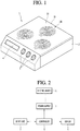
- Fig. 1 is a perspective view illustrating an electric stove, to which an electric heater according to an embodiment of the present invention is applied
- Fig. 2 is a control block diagram of an electric stove, to which an electric heater according to an embodiment of the present invention is applied.
- the electric heater 1 of the present invention may configure a portion of an electric stove such as a cooktop.
- the electric stove may include a cabinet 2 forming an outer appearance.
- the electric heater 1 may be provided on the cabinet 2.
- the upper surface of the cabinet 2 may be opened and the electric heater 1 may be provided on the upper surface of the cabinet 2.
- the electric stove may include an input unit 3 for manipulating the electric stove and a display 4 for displaying a variety of information such as information on the electric stove.
- the electric stove may further include a power supply 5 connected to the electric heater 1 to apply current to the electric heater 1.
- the electric stove may further include a controller 6 for controlling the power supply 5 and the display 4 according to input of the input unit 3.
- the electric heater 1 may be provided on the cabinet 2 such that the upper surface thereof is exposed to the outside.
- An object to be heated by the electric stove may be placed on the upper surface of the electric heater 1, and the upper surface of the electric heater 1 may be a surface in which the object to be heated is seated.
- Fig. 3 is a cross-sectional view illustrating an electric heater according to an embodiment of the present invention.
- the electric heater 1 may include a substrate 10 and a plurality of plane heating elements 100 formed on one surface of the substrate 10.
- the substrate 10 may be an insulating substrate having a conductor pattern formed on a surface thereof.
- the upper surface of the substrate 10 may be a surface 13 in which the object to be heated is seated.
- the lower surface of the substrate 10 may be a surface 14 in which the plane heating elements 100, 200, and 300 are formed.
- the substrate 10 may include only a base 11 formed of an insulating material or may include a base 11 formed of an insulating material or a non-insulating material and an insulating layer 12 formed on one surface of the base 11.
- the base 11 may be glass and the insulating layer 12 may be formed on the lower surface of the glass using a coating or a printing method.
- the plane heating element 100 may be directly formed on one surface of the base 11 formed of an insulating material or may be formed on the insulating layer 12.
- the base 11 may be formed in a shape of a plate on which the object to be heated is placed or in a shape of a container in which the object to be heated is received.
- the insulating layer 12 may be formed on the lower surface of the base 11.
- the insulating layer 12 may be formed on the entire lower surface of the base 11 or may be formed on a portion of the lower surface of the base 11.
- the insulating layer 12 may be formed only in a zone in which the plane heating element 100 will be formed.
- the insulating layer 12 may configure the entire lower surface of the substrate 10 or a portion of the lower surface of the substrate 10.
- the plane heating element 100 may be formed on the lower surface 14 of the insulating layer 12.
- the plane heating element 100 may have a size smaller than the substrate 10 and the lower surface of the substrate 10 may have a heated zone H, in which the plane heating element 100 is formed, and an unheated zone UH located around the heated zone H.
- the heater 1 may further include a coating layer 18 surrounding the plane heating element 100.
- the coating layer 18 may be formed of an electrically insulating material to protect the plane heating element 100.
- the substrate 10 of the present embodiment may be formed of a flexible material, such as a flexible insulating film.
- the electric heater 1 may be a flexible planar heater. Such a flexible planar heater may be attached to a member, on which the object to be heated is placed, to heat the object to be heated, like the upper plate of the electric stove.
- Fig. 4 is a plan view illustrating a single-type plane heating element according to an embodiment of the present invention
- Figs. 5a and 5b are cross-sectional views taken along line A-A' and line B-B' in Fig. 4 .
- the single-type plane heating element according to the present invention comprises only a first plane heating element 100 composed of one hot wire as illustrated in Fig. 4 , and includes a pattern portion 110 in which hot wires are arranged in a predetermined shape, and an electrode portion 120 for supplying current to the pattern portion 110.
- the pattern portion 110 is configured with a heating unit in which a certain kind of hot wires are closely arranged in a limited area having a circular shape, connects between a start point and an end point, which are located to the outermost side, along various paths, and is configured with a symmetrical shape with respect to the center of the pattern portion 110 illustrated in Fig. 4 in the lateral direction.
- the pattern portion 110 includes a plurality of tracks 111 spaced apart from each other and increasing in size from the center toward the outside, and a plurality of bridges 112 connecting the tracks 111 in series.
- the area where the pattern portion 110 is formed and the length of the hot wire which constitutes the pattern portion 110 may be set in proportion to the required power.
- the electrodes 120 are formed of a unheated unit having a relatively lower heating value than the pattern portion 110, the electrodes 120 include a positive electrode 121 to which current is input and a negative electrode 122 to which current is output, and the positive electrode 121 and the negative electrode 122 may be horizontally located outside the pattern portion 110 with a predetermined gap therebetween.
- the positive electrode 121 is a portion which extends from the start point of the pattern portion 110 and is connected to an external input terminal
- the negative electrode 122 is a portion which extends from the end point of the pattern portion 110 and is connected to the external output terminal.
- the pattern portion 110 acts as a kind of resistance to generate heat at 600°C or higher, and an object to be heated placed on the pattern portion 110 is cooked.
- the electrode portion 120 is configured to generate heat at a temperature of 200°C or less, or substantially no heat.
- the width of the electrode portion 120 may be configured to be larger than the width of the pattern portion 110 in order to greatly reduce the resistance of the electrode portion 120.
- the thickness of the electrode portion 120 is thicker than the thickness of the pattern portion 110.
- the thickness T 2 of the positive electrode 121 is configured to be larger than the thickness T 1 of the pattern portion-side track 111 and can be formed in a range of 1.3 to 2.0 with respect to the thickness T 1 of the track 111 but it is not limited thereto.
- the negative electrode 122 may also be configured to be thicker than the thickness T 1 of the track 111.
- the track 111 does not have a gently curved shape, that is, a relatively large radius of curvature is not configured, whereas the bridge 112 has a sharply curved shape, that is a relatively small radius of curvature is configured.
- the resistance of the bridge 112 is configured to be small.
- the bridge 112 may have a wide width in order to reduce the resistance, but considering the limited area, it is preferable that the bridge 112 has a large thickness.
- the thickness T3 of the bridge 112 is configured to be larger than the thickness T 1 of the track 111 and may be formed in a range of 1.3 to 2.0 with respect to the thickness T 1 of the track 111, but is not limited thereto.
- the electric energizing material is printed on the surface of the substrate in a form of tracks, bridges, and electrode portions, is dried, and then the same electric energizing material or different kinds of electric energizing materials is printed on the surface of the substrate once again in the form of a bridge and an electrode portion, and then the single-type plane heating element can be manufactured in the form of firing.
- the plane heating element having the bridges and electrode portions thicker than the tracks it is possible to easily manufacture the plane heating element having the bridges and electrode portions thicker than the tracks, and the electrode portion can be constituted of the unheated unit and the local heating of the bridge can be solved.
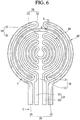
- Fig. 6 is a plan view illustrating a dual-type plane heating element according to an embodiment of the present invention
- Figs. 7a and 7b are cross-sectional views taken along lines C-C' and D-D' in Fig. 6 .
- the dual-type plane heating element includes an inner plane heating element 100 located at the center of the same plane, and an outer plane heating element 200 located to surround the inner plane heating element 100.
- the inner plane heating element 100 includes an inner pattern portion 110 arranged in a predetermined shape, an inner electrode portion 120 supplying a current to the inner pattern portion 110, and an inner connector 130 connecting between the inner pattern portion 110 and the inner electrode portions 120.
- the inner pattern portion 110 and the inner electrode portion 120 are configured in the same manner as the pattern portion and the electrode portion described in the above-described single-type plane heating element, and a detailed description thereof will be omitted.
- the inner connector 130 is formed of an auxiliary heating unit capable of generating heat at the same temperature as the inner pattern portion 110.
- the inner connector 130 is a portion which extends from the start point and the end point of the inner pattern portion 110 to the inner electrode portion 120.
- the inner connector 130 may be located between openings provided at one side of the outer pattern portion 210 to be described below, that is, at least one pair of outer bridges 212.
- One inner connector 131 connects between the start point of the inner pattern portion 110 and the inner positive electrode 121 and the other inner connector 132 connects between the end point of the inner pattern portion 110 and the inner negative electrode 122 to each other.
- the inner connectors 131 and 132 are directly connected to the inner positive electrode 121 and the inner negative electrode 122 so that a large potential difference is generated between the inner connectors 131 and 132 during current flow and the inner connectors 131 and 132 may be short-circuited.
- the inner connectors 131 and 132 must be installed far so as to maintain an insulation gap, and are located parallel to each other so that the gap between the inner connectors 131 and 132 should be maintained at least 20 mm or more, but they are not limited to these.
- the outer plane heating element 200 includes an outer pattern portion 210 arranged outside the inner pattern portion 110 in a predetermined shape and an outer electrode portion 220 connected to the outer pattern portion 210.
- the outer pattern portion 210 is formed by a heating unit closely arranged in a ring-shaped limited area surrounding the outside of the inner pattern portion 110, the inner pattern portion 210 connects between the start point and the end point, which are located at the innermost side, along various paths and is configured in a symmetrical shape in the lateral direction.
- the outer pattern portion 210 may also include a plurality of outer tracks 211 and a plurality of outer bridges 212 like the inner pattern portion 110.
- a portion of the inner connectors 131 and 132 may be located between the opening portions provided on one side of the outer pattern portion 210, that is, the outer bridges 212.
- the outer electrode portion 220 includes an unheated unit extended from a start point and an end point of the outer pattern portion 210, and the outer electrode portion 220 includes an outer positive electrode 221 and an outer negative electrode 222 located horizontally.
- the outer electrode portion 220 is located in the same direction as the inner electrode portion 120 in order to supply current to the inner/outer plane heating elements 100 and 200 by one power supply.
- the outer pattern portion 210 is formed of a heating unit which generates heat at 600°C or more, but the outer electrode portion 220 should be formed of an unheated unit which generates heat at 200°C or less and hardly generates heat.
- the outer electrode portion 220 may be thicker than the outer pattern portion 210 when considering the limited area on which the outer electrode portion 220 can be formed so that the resistance of the outer electrode portion 220 is preferably configured to be substantially small.
- the thickness T 2 of the outer positive electrode 221 is formed to be thicker than the thickness T 1 of the outer track 211, and the thickness T 2 of the outer track 211 may be formed in a range of 1.3 to 2.0 with respect to the thickness T1 of the outer track 211, but it is not limited thereto.
- outer negative electrode 222 may be also formed to be thicker than the thickness T 1 of the outer track 221.
- the outer bridge 212 is formed in an excessively curved shape as compared with the outer track 211, the outer bridge 212 can be locally heated due to a difference in current density between the inside and the outside. Therefore, it is preferable that the outer bridge 212 also have a very small resistance in order to prevent local heating.
- the thickness T 3 of the outer bridge 212 is formed to be thicker than the thickness T 1 of the outer track 211 and may be formed in a range in a range of 1.3 to 2.0 with respect to the thickness T 1 of the outer track 211, but it is not limited thereto.
- the outer plane heating element configured as described above can configure the outer bridge and the outer electrode portion to be thicker than the outer tracks by a process of printing at least twice like the single-type plane heating element.
- Fig. 8 is a plan view illustrating a triple-type plane heating element according to an embodiment of the present invention
- Figs. 9a and 9b are cross-sectional views taken along lines E-E' and F-F' in Fig. 8 .
- the triple-type plane heating element includes a first plane heating element 100 located at the center of the same plane, a second plane heating element 200 located to surround the first plane heating element 100, and a third plane heating element 300 located to surround the second plane heating element 200.
- the first plane heating element 100 includes a first pattern portion 110, a first electrode portion 120, and a first connector 130 and is configured like the inner pattern portion, the inner electrode portion, and the inner connector described in a dual pattern-type inner plane heating element, a detailed description thereof will be omitted.
- the second plane heating element 200 includes the second pattern portion 210, the second electrode portion 220, and the second connector 230 and is configured like the outer pattern portion and the outer electrode portion described in the dual pattern-type outer plane heating element, a detailed description thereof will be omitted.
- the second connector 230 is formed as an auxiliary heating unit capable of generating heat at the same temperature as that of the second pattern portion 210, is a portion extended from the start point and the end point of the second pattern portion 210 to the second electrode portion 220, and is provided outside the first connector 130.
- first and second connectors 130 and 230 may be located between the opening portions provided at one side of the second and third pattern portions 210 and 310, that is, at least a pair of second and third bridges 212 and 312.
- One second connector 231 connects between the start point of the second pattern portion 210 and the second positive electrode 221 and the other second connector 232 connects between the end point of the second pattern portion 210 and the second negative electrode 222.
- the third plane heating element 300 includes a third pattern portion 310 arranged in a predetermined shape outside the second pattern portion 210 and a third electrode portion 320 connected to the third pattern portion 310.
- the third pattern portion 310 is formed by a heating unit closely arranged in a ring-shaped limited area surrounding outside the second pattern portion 210, connects between the start point and the end point, which are located at the outermost side, along various paths, and is configured in a symmetrical shape in the lateral direction.
- the third pattern portion 310 may include a plurality of third tracks 311 and a plurality of third bridges 312 like the second pattern portion 210.
- the third electrode portion 320 includes an unheated unit extending from the start point and the end point of the third pattern portion 310 and includes the third positive electrode 321 and the third negative electrode 322, which are located horizontally.
- the third electrode portion 320 is located in a direction opposite to those of the first and second electrode portions 120 and 220.
- the third pattern portion 310 may include a heating unit which generates heat at a temperature of 600°C or higher, but the third electrode portion 320 should be formed of an unheated unit which generates heat at 200°C or less, or hardly generates heat.
- the third electrode portion 320 is configured to have a much smaller resistance like the first and second electrode portions 120 and 220.
- the thickness T 2 of the third positive electrode 321 is formed to be thicker than the thickness T 1 of the third track 311, and can be formed in a range of 1.3 to 2.0 with respect to the thickness T 1 of the third track 311, but it is not limited thereto.
- the third negative electrode 322 may be also formed to be thicker than the third track 311.
- the third bridge 312 is configured to have a very small resistance in order to eliminate the local heating due to the current density difference, like the first and second bridges 112 and 212.
- the thickness T 3 of the third bridge 312 is formed to be thicker than the thickness T 1 of the third track 311 and can be formed in a range of 1.3 to 2.0 with respect to the thickness T 3 of the third bridge 311, but it is not limited thereto.
- the third plane heating element configured as described above may be also formed by being thicker the third bridge and the third electrode portions than the third track by a process of printing at least twice like the dual-type first and second plane heating elements.
Landscapes
- Engineering & Computer Science (AREA)
- Chemical & Material Sciences (AREA)
- Ceramic Engineering (AREA)
- Combustion & Propulsion (AREA)
- Mechanical Engineering (AREA)
- General Engineering & Computer Science (AREA)
- Food Science & Technology (AREA)
- Inorganic Chemistry (AREA)
- Resistance Heating (AREA)
- Surface Heating Bodies (AREA)
Abstract
Description
- The present invention relates to an electric heater applied to a cooking appliance, and more particularly to an electric heater including a plane heating element capable of effectively lowering a heating temperature of an electrode portion even when an electrode portion is formed within a limited area.
- In general, a cooking appliance refers to a device for heating and cooking food using gas or electricity. Various products such as a microwave oven using microwaves, an oven using a heater, a gas stove using gas, an electric stove using electricity, or a cooktop including a gas stove or an electric stove have come into widespread use.
- The gas stove directly generates flame using gas as a heating source, while the electric stove heats a container and food placed on a top plate thereof using electricity.
- In the gas stove, heat loss caused by flame is large and contaminants are discharged due to incomplete combustion, thereby polluting room air. Therefore, recently, electric stoves are attracting attention.
- Electric stoves may be classified into an inductive electric stove which directly heats a container in which a magnetic field is generated by a magnetic induction method, and a resistive electric stove which heats a top surface made of ceramic using a hot wire.
- The inductive electric stove has a short cooking time at a high temperature and must use a dedicated magnetic container. The resistive electric stove may use an existing container but has a relatively long cooking time.
- Even if an existing resistive electric stove uses a heating element made of a nichrome wire, an electric heater using a plane heating element is being developed in order to reduce the thickness of the heating element.
- In addition, in order to shorten the cooking time, a resistive electric stove using an electric heater capable of heating a limited area at a high temperature is being developed.
- As an example of such an electric heater, Korean Patent Registration No.
10-1762159 B1 (August 4, 2017 - In the electric heater, the temperature distribution of an object to be heated may be changed according to the shape (that is, the pattern) of the plane heating element, and the plane heating element may be formed in a shape capable of heating the object to be heated as uniformly as possible.
- The plane heating element of the electric heater includes a plurality of tracks having a straight-line shape or an arc shape and adjacent tracks of the plurality of tracks may be connected through a bridge (or a track).
- As another example of the heater, European Patent Publication No.
EP 0,228,808 A2 (published on July 15, 1987 ) discloses a temperature sensitive device. Such a device is configured by printing a heater track made of a conductive material and a plurality of electrodes on a ceramic coating layer. As current is supplied through the electrodes, radiant heat is generated in the heater track. -
- (Patent Literature 1) Korean Patent Registration No.
10-1762159 B1 (August 4, 2017 - (Patent Literature 2) European Patent Publication No.
EP 0,228,808 A2 (published on July 15, 1987 ) - However, the existing plane heating elements include a heating unit in which a single hot wire is formed within a limited area in a predetermined pattern shape, and the heating portion is designed to have a high resistance in order to heat at a high temperature of 500°C or higher.
- Of course, an electrode for supplying current to the pattern is provided, and the electrode must be configured to have a low resistance so as not to heat.
- According to the related art, in order to configure the resistance of the electrode to be significantly lower than the resistance of the pattern, the electrode is configured to be much wider than the width of the pattern.
- However, the required power required for each size of the cooking appliance differs, and there is a limit in configuring the pattern only by one hot wire in order to heat up to a high temperature step by step according to the user's need.
- Therefore, a plane heating heater having a plurality of patterns and a plurality of electrodes can be configured, but it must be provided in a limited area.
- However, in order to connect a plurality of electrodes to one power supply, the electrodes must be located close to each other in a limited area in the same direction, and there is a limit to increase the resistance of the electrodes by making the electrodes wider than the width of the pattern. Meanwhile, if a pattern is formed in a limited area and generates heat at a high temperature, there is a problem that local heat is generated according to the shape of the pattern, thereby breaking the heat wire.
- In other words, a path difference in which current flows according to the pattern shape is generated, and a larger path difference causes a large deviation of the current density, local heating occurs at a portion having a high current density, and a hot wire breakdown phenomenon occurs.
- The present invention has been made in order to solve the above problems of the related art, and an object of the present invention is to provide an electric heater including a plane heating element capable of significantly reducing the resistance of an electrode in a limited area.
- Another object of the present invention is to provide an electric heater including a plane heating element capable of preventing local heating even if a difference in current density inside the pattern portion is large.
- According to an embodiment of the present invention, there is provided an electric heater including: a substrate 10 (an insulating material capable of forming a conductor pattern on a surface of an insulating substrate); and a
plane heating element 100 configured to be formed on one surface of thesubstrate 10, in which theplane heating element 100 includes: apattern portion 110 configured to connect a start point and an end point to each other; and anelectrode portion 120 configured to be connected to the start point and the end point of thepattern portion 110, and theelectrode portion 120 is formed to be thicker than the thickness of thepattern portion 110. Therefore, the resistance of the electrode can be formed to be remarkably small in a limited area, so that an unheated unit can be constituted. - At this time, the
electrode portion 120 may include apositive electrode 121 located outside thepattern portion 110 and connected to the start point of thepattern portion 110, and anegative electrode 122 located outside thepattern portion 110 so as to be horizontal to thepositive electrode 121 and connected to the end point of thepattern portion 110. - In addition, in the present invention, the
pattern portion 110 may include a plurality oftracks 111 spaced apart from each other and having an arc shape increasing from the inside to the outside, and a plurality ofbridges 112 connecting thetracks 111 in series. - At this time, the
pattern portion 110 may be configured with a symmetrical shape with respect to a reference line passing through the center of thepattern portion 110. - In addition, in the present invention, the
electrode portion 120 may be formed to be thicker than the thickness of thetrack 111, the thickness of theelectrode portion 120 may be formed within a range of 1.3 to 2.0 with respect to the thickness of thetrack 111, and theelectrode portion 120 may generate heat at 200°C or less during current flows. - In addition, in the present invention, the
bridge 112 may be formed to be thicker than the thickness of thetrack 111, the thickness of thebridge 112 may be formed within a range of 1.3 to 2.0 with respect to the thickness of thetrack 111, and thebridge 112 may generate heat at 500□ or less during current flows. - Therefore, even if the difference in current density flowing along the bridge is large, the resistance of the bridge can be made small so that it is possible to prevent the bridge portion from being subjected to local heating and thereby causing insulation breakdown.
- In addition, in the present invention, the plane heating element may include an inner side
plane heating element 100 formed at the center thereof, and at least one outerplane heating element 200 provided to surround the innerplane heating element 100, and the electrode portion may include aninner electrode portion 120 for supplying current to the innerplane heating element 110, and anouter electrode portion 220 for supplying current to the outerplane heating element 200, that is, the pattern portion can be configured as a multi-pattern, and the heat intensity at various stages can be realized. - According to another embodiment of the present invention, there is provided an electric heater including: a substrate 10 (an insulating material capable of forming a conductor pattern on a surface of an insulating substrate); and a
plane heating element 100 configured to be formed on one surface of thesubstrate 10, in which theplane heating element 100 includes: apattern portion 110 configured to connect a start point and an end point to each other; and anelectrode portion 120 configured to be connected to the start point and the end point of thepattern portion 110, and thepattern portion 110 includes a plurality oftracks 111 spaced apart from each other and having an arc shape increasing from the inside to the outside, and theelectrode portion 120 is formed to be thicker than the thickness of thetrack 111. - In addition, in the present invention, the thickness of the
electrode portion 120 may be formed within a range of 1.3 to 2.0 with respect to the thickness of thetrack 111. - In addition, in the present invention, the
pattern portion 110 may further include a plurality ofbridges 112 connecting thetracks 111 in series and thebridge 112 may be formed to be thicker than the thickness of thetrack 111. - In addition, in the present invention, the thickness of the
bridge 112 may be formed in a range of 1.3 to 2.0 with respect to the thickness of thetrack 111. - The electric heater according to the present invention can be configured to be thicker than the pattern portion even if the electrode portion is formed in a limited area, and the resistance of the electrode portion can be greatly reduced. Therefore, the heating temperature of the electrode portion formed in a limited area can be effectively lowered.
- In addition, in the present invention, the bridges having a large difference in current density among the pattern portions are made thicker than the tracks, so that the resistance of the bridges can be configured to be significantly reduced. Therefore, it is possible to prevent the local heating and the hot wire breakage of the bridge portion of the pattern portion, and the entire area on which the pattern portion is formed can be uniformly heated.
- In addition, in the present invention, it is possible to constitute a multi-pattern portion on the same plane and to provide heating intensity at various stages. Therefore, the limited area can be gradually heated to a high temperature
-
-
Fig. 1 is a perspective view illustrating an electric stove to which an electric heater is applied according to an embodiment of the present invention. -
Fig. 2 is a control block diagram of an electric stove to which an electric heater according to an embodiment of the present invention is applied. -
Fig. 3 is a cross-sectional view illustrating an electric heater according to an embodiment of the present invention. -
Fig. 4 is a plan view illustrating a single-type plane heating element according to an embodiment of the present invention. -
Figs. 5a and 5b are cross-sectional views taken along line A-A' and line B-B' inFig. 4 . -
Fig. 6 is a plan view illustrating a dual-type plane heating element according to an embodiment of the present invention. -
Figs. 7a and 7b are cross-sectional views taken along lines C-C' and D-D' inFig. 6 . -
Fig. 8 is a plan view illustrating a triple-type plane heating element according to an embodiment of the present invention. -
Figs. 9a and 9b are cross-sectional views taken along lines E-E' and F-F' inFig. 8 . - Hereinafter, the present embodiment will be described in detail with reference to the accompanying drawings.
-
Fig. 1 is a perspective view illustrating an electric stove, to which an electric heater according to an embodiment of the present invention is applied, andFig. 2 is a control block diagram of an electric stove, to which an electric heater according to an embodiment of the present invention is applied.
Theelectric heater 1 of the present invention may configure a portion of an electric stove such as a cooktop. - The electric stove may include a
cabinet 2 forming an outer appearance. Theelectric heater 1 may be provided on thecabinet 2. The upper surface of thecabinet 2 may be opened and theelectric heater 1 may be provided on the upper surface of thecabinet 2. - The electric stove may include an
input unit 3 for manipulating the electric stove and adisplay 4 for displaying a variety of information such as information on the electric stove. In addition, the electric stove may further include apower supply 5 connected to theelectric heater 1 to apply current to theelectric heater 1. The electric stove may further include acontroller 6 for controlling thepower supply 5 and thedisplay 4 according to input of theinput unit 3. - The
electric heater 1 may be provided on thecabinet 2 such that the upper surface thereof is exposed to the outside. An object to be heated by the electric stove may be placed on the upper surface of theelectric heater 1, and the upper surface of theelectric heater 1 may be a surface in which the object to be heated is seated. -
Fig. 3 is a cross-sectional view illustrating an electric heater according to an embodiment of the present invention. - The
electric heater 1 may include asubstrate 10 and a plurality ofplane heating elements 100 formed on one surface of thesubstrate 10. - The
substrate 10 may be an insulating substrate having a conductor pattern formed on a surface thereof. The upper surface of thesubstrate 10 may be asurface 13 in which the object to be heated is seated. The lower surface of thesubstrate 10 may be asurface 14 in which theplane heating elements - The
substrate 10 may include only a base 11 formed of an insulating material or may include a base 11 formed of an insulating material or a non-insulating material and an insulatinglayer 12 formed on one surface of thebase 11. - The base 11 may be glass and the insulating
layer 12 may be formed on the lower surface of the glass using a coating or a printing method. - The
plane heating element 100 may be directly formed on one surface of the base 11 formed of an insulating material or may be formed on the insulatinglayer 12. - The base 11 may be formed in a shape of a plate on which the object to be heated is placed or in a shape of a container in which the object to be heated is received.
- The insulating
layer 12 may be formed on the lower surface of thebase 11. The insulatinglayer 12 may be formed on the entire lower surface of the base 11 or may be formed on a portion of the lower surface of thebase 11. The insulatinglayer 12 may be formed only in a zone in which theplane heating element 100 will be formed. The insulatinglayer 12 may configure the entire lower surface of thesubstrate 10 or a portion of the lower surface of thesubstrate 10. - The
plane heating element 100 may be formed on thelower surface 14 of the insulatinglayer 12. Theplane heating element 100 may have a size smaller than thesubstrate 10 and the lower surface of thesubstrate 10 may have a heated zone H, in which theplane heating element 100 is formed, and an unheated zone UH located around the heated zone H. - The
heater 1 may further include acoating layer 18 surrounding theplane heating element 100. Thecoating layer 18 may be formed of an electrically insulating material to protect theplane heating element 100.
Thesubstrate 10 of the present embodiment may be formed of a flexible material, such as a flexible insulating film. In this case, theelectric heater 1 may be a flexible planar heater. Such a flexible planar heater may be attached to a member, on which the object to be heated is placed, to heat the object to be heated, like the upper plate of the electric stove. -
Fig. 4 is a plan view illustrating a single-type plane heating element according to an embodiment of the present invention, andFigs. 5a and 5b are cross-sectional views taken along line A-A' and line B-B' inFig. 4 . - The single-type plane heating element according to the present invention comprises only a first
plane heating element 100 composed of one hot wire as illustrated inFig. 4 , and includes apattern portion 110 in which hot wires are arranged in a predetermined shape, and anelectrode portion 120 for supplying current to thepattern portion 110. - The
pattern portion 110 is configured with a heating unit in which a certain kind of hot wires are closely arranged in a limited area having a circular shape, connects between a start point and an end point, which are located to the outermost side, along various paths, and is configured with a symmetrical shape with respect to the center of thepattern portion 110 illustrated inFig. 4 in the lateral direction. - According to the embodiment, the
pattern portion 110 includes a plurality oftracks 111 spaced apart from each other and increasing in size from the center toward the outside, and a plurality ofbridges 112 connecting thetracks 111 in series. - At this time, the area where the
pattern portion 110 is formed and the length of the hot wire which constitutes thepattern portion 110 may be set in proportion to the required power. - The
electrodes 120 are formed of a unheated unit having a relatively lower heating value than thepattern portion 110, theelectrodes 120 include apositive electrode 121 to which current is input and anegative electrode 122 to which current is output, and thepositive electrode 121 and thenegative electrode 122 may be horizontally located outside thepattern portion 110 with a predetermined gap therebetween. - The
positive electrode 121 is a portion which extends from the start point of thepattern portion 110 and is connected to an external input terminal, and thenegative electrode 122 is a portion which extends from the end point of thepattern portion 110 and is connected to the external output terminal. - When a current is supplied to the single-type plane heating element having such a structure, current flows sequentially along the
positive electrode 121, thepattern portion 110, and thenegative electrode 122. - At this time, the
pattern portion 110 acts as a kind of resistance to generate heat at 600°C or higher, and an object to be heated placed on thepattern portion 110 is cooked. - However, it is preferable that the
electrode portion 120 is configured to generate heat at a temperature of 200°C or less, or substantially no heat. - Of course, the width of the
electrode portion 120 may be configured to be larger than the width of thepattern portion 110 in order to greatly reduce the resistance of theelectrode portion 120. - However, since the area for forming the
electrode portion 120 is limited, it is preferable that the thickness of theelectrode portion 120 is thicker than the thickness of thepattern portion 110. - As illustrated in
Fig. 5a , the thickness T2 of thepositive electrode 121 is configured to be larger than the thickness T1 of the pattern portion-side track 111 and can be formed in a range of 1.3 to 2.0 with respect to the thickness T1 of thetrack 111 but it is not limited thereto. - Of course, the
negative electrode 122 may also be configured to be thicker than the thickness T1 of thetrack 111. - On the other hand, when current flows along the
pattern portion 110, thetrack 111 does not have a gently curved shape, that is, a relatively large radius of curvature is not configured, whereas thebridge 112 has a sharply curved shape, that is a relatively small radius of curvature is configured. - At this time, a difference in density of the current flowing between the inside and outside of the
bridge 112 is large, and thebridge 112 excessively generates local heat as compared with thetrack 111. - Therefore, in order to prevent local heating of the
bridge 112, it is preferable that the resistance of thebridge 112 is configured to be small. - Of course, like the
electrode portion 120, thebridge 112 may have a wide width in order to reduce the resistance, but considering the limited area, it is preferable that thebridge 112 has a large thickness. - As illustrated in
Fig. 5b , the thickness T3 of thebridge 112 is configured to be larger than the thickness T1 of thetrack 111 and may be formed in a range of 1.3 to 2.0 with respect to the thickness T1 of thetrack 111, but is not limited thereto. - In order to manufacture the single-type plane heating element having the above-described structure, the electric energizing material is printed on the surface of the substrate in a form of tracks, bridges, and electrode portions, is dried, and then the same electric energizing material or different kinds of electric energizing materials is printed on the surface of the substrate once again in the form of a bridge and an electrode portion, and then the single-type plane heating element can be manufactured in the form of firing.
- In addition to such a printing process, various processes such as a spray process can be used, but it is not limited thereto.
- As described above, it is possible to easily manufacture the plane heating element having the bridges and electrode portions thicker than the tracks, and the electrode portion can be constituted of the unheated unit and the local heating of the bridge can be solved.
-
Fig. 6 is a plan view illustrating a dual-type plane heating element according to an embodiment of the present invention, andFigs. 7a and 7b are cross-sectional views taken along lines C-C' and D-D' inFig. 6 . - As illustrated in
Fig. 6 , the dual-type plane heating element according to the present invention includes an innerplane heating element 100 located at the center of the same plane, and an outerplane heating element 200 located to surround the innerplane heating element 100. - The inner
plane heating element 100 includes aninner pattern portion 110 arranged in a predetermined shape, aninner electrode portion 120 supplying a current to theinner pattern portion 110, and aninner connector 130 connecting between theinner pattern portion 110 and theinner electrode portions 120. - The
inner pattern portion 110 and theinner electrode portion 120 are configured in the same manner as the pattern portion and the electrode portion described in the above-described single-type plane heating element, and a detailed description thereof will be omitted. - The
inner connector 130 is formed of an auxiliary heating unit capable of generating heat at the same temperature as theinner pattern portion 110. Theinner connector 130 is a portion which extends from the start point and the end point of theinner pattern portion 110 to theinner electrode portion 120. - The
inner connector 130 may be located between openings provided at one side of theouter pattern portion 210 to be described below, that is, at least one pair ofouter bridges 212. - One
inner connector 131 connects between the start point of theinner pattern portion 110 and the innerpositive electrode 121 and the otherinner connector 132 connects between the end point of theinner pattern portion 110 and the innernegative electrode 122 to each other. - Since the
inner connectors positive electrode 121 and the innernegative electrode 122 so that a large potential difference is generated between theinner connectors inner connectors - Therefore, in order to prevent a short circuit between the
inner connectors inner connectors inner connectors - The outer
plane heating element 200 includes anouter pattern portion 210 arranged outside theinner pattern portion 110 in a predetermined shape and anouter electrode portion 220 connected to theouter pattern portion 210. - The
outer pattern portion 210 is formed by a heating unit closely arranged in a ring-shaped limited area surrounding the outside of theinner pattern portion 110, theinner pattern portion 210 connects between the start point and the end point, which are located at the innermost side, along various paths and is configured in a symmetrical shape in the lateral direction. - According to an embodiment, the
outer pattern portion 210 may also include a plurality ofouter tracks 211 and a plurality ofouter bridges 212 like theinner pattern portion 110. - In addition, a portion of the
inner connectors outer pattern portion 210, that is, theouter bridges 212. - The
outer electrode portion 220 includes an unheated unit extended from a start point and an end point of theouter pattern portion 210, and theouter electrode portion 220 includes an outerpositive electrode 221 and an outernegative electrode 222 located horizontally. - Of course, the
outer electrode portion 220 is located in the same direction as theinner electrode portion 120 in order to supply current to the inner/outerplane heating elements - When current is supplied to the outer
plane heating element 200 configured as described above, a current flows sequentially along the outerpositive electrode 221, theouter pattern portion 210, and the outernegative electrode 222 like the internal plane heating element. - At this time, the
outer pattern portion 210 is formed of a heating unit which generates heat at 600°C or more, but theouter electrode portion 220 should be formed of an unheated unit which generates heat at 200°C or less and hardly generates heat. - The
outer electrode portion 220 may be thicker than theouter pattern portion 210 when considering the limited area on which theouter electrode portion 220 can be formed so that the resistance of theouter electrode portion 220 is preferably configured to be substantially small. - As illustrated in
Fig, 7a , the thickness T2 of the outerpositive electrode 221 is formed to be thicker than the thickness T1 of theouter track 211, and the thickness T2 of theouter track 211 may be formed in a range of 1.3 to 2.0 with respect to the thickness T1 of theouter track 211, but it is not limited thereto. - Of course, the outer
negative electrode 222 may be also formed to be thicker than the thickness T1 of theouter track 221. - In addition, since the
outer bridge 212 is formed in an excessively curved shape as compared with theouter track 211, theouter bridge 212 can be locally heated due to a difference in current density between the inside and the outside. Therefore, it is preferable that theouter bridge 212 also have a very small resistance in order to prevent local heating. - As illustrated in
Fig. 7b , the thickness T3 of theouter bridge 212 is formed to be thicker than the thickness T1 of theouter track 211 and may be formed in a range in a range of 1.3 to 2.0 with respect to the thickness T1 of theouter track 211, but it is not limited thereto. - The outer plane heating element configured as described above can configure the outer bridge and the outer electrode portion to be thicker than the outer tracks by a process of printing at least twice like the single-type plane heating element.
-
Fig. 8 is a plan view illustrating a triple-type plane heating element according to an embodiment of the present invention, andFigs. 9a and 9b are cross-sectional views taken along lines E-E' and F-F' inFig. 8 . - As illustrated in
Fig. 8 , the triple-type plane heating element according to the present invention includes a firstplane heating element 100 located at the center of the same plane, a secondplane heating element 200 located to surround the firstplane heating element 100, and a thirdplane heating element 300 located to surround the secondplane heating element 200. - Since the first
plane heating element 100 includes afirst pattern portion 110, afirst electrode portion 120, and afirst connector 130 and is configured like the inner pattern portion, the inner electrode portion, and the inner connector described in a dual pattern-type inner plane heating element, a detailed description thereof will be omitted. - Since the second
plane heating element 200 includes thesecond pattern portion 210, thesecond electrode portion 220, and thesecond connector 230 and is configured like the outer pattern portion and the outer electrode portion described in the dual pattern-type outer plane heating element, a detailed description thereof will be omitted. - However, the
second connector 230 is formed as an auxiliary heating unit capable of generating heat at the same temperature as that of thesecond pattern portion 210, is a portion extended from the start point and the end point of thesecond pattern portion 210 to thesecond electrode portion 220, and is provided outside thefirst connector 130. - Accordingly, the first and
second connectors third pattern portions third bridges - One
second connector 231 connects between the start point of thesecond pattern portion 210 and the secondpositive electrode 221 and the othersecond connector 232 connects between the end point of thesecond pattern portion 210 and the secondnegative electrode 222. - The third
plane heating element 300 includes athird pattern portion 310 arranged in a predetermined shape outside thesecond pattern portion 210 and athird electrode portion 320 connected to thethird pattern portion 310. - The
third pattern portion 310 is formed by a heating unit closely arranged in a ring-shaped limited area surrounding outside thesecond pattern portion 210, connects between the start point and the end point, which are located at the outermost side, along various paths, and is configured in a symmetrical shape in the lateral direction. - According to an embodiment, the
third pattern portion 310 may include a plurality ofthird tracks 311 and a plurality ofthird bridges 312 like thesecond pattern portion 210. - The
third electrode portion 320 includes an unheated unit extending from the start point and the end point of thethird pattern portion 310 and includes the thirdpositive electrode 321 and the thirdnegative electrode 322, which are located horizontally. - Of course, in order to supply current to the first and second
plane heating elements plane heating element 300 by the other power supply, thethird electrode portion 320 is located in a direction opposite to those of the first andsecond electrode portions - Current sequentially flows along the third
positive electrode 321, thethird pattern portion 310, and the thirdnegative electrode 322 when a current is supplied to the thirdplane heating element 300 configured as described above. - Similarly, the
third pattern portion 310 may include a heating unit which generates heat at a temperature of 600°C or higher, but thethird electrode portion 320 should be formed of an unheated unit which generates heat at 200°C or less, or hardly generates heat. - Therefore, it is preferable that the
third electrode portion 320 is configured to have a much smaller resistance like the first andsecond electrode portions - As illustrated in
Fig. 9a , the thickness T2 of the thirdpositive electrode 321 is formed to be thicker than the thickness T1 of thethird track 311, and can be formed in a range of 1.3 to 2.0 with respect to the thickness T1 of thethird track 311, but it is not limited thereto. - Of course, the third
negative electrode 322 may be also formed to be thicker than thethird track 311. - In addition, it is preferable that the
third bridge 312 is configured to have a very small resistance in order to eliminate the local heating due to the current density difference, like the first andsecond bridges - As illustrated in
Fig. 9b , the thickness T3 of thethird bridge 312 is formed to be thicker than the thickness T1 of thethird track 311 and can be formed in a range of 1.3 to 2.0 with respect to the thickness T3 of thethird bridge 311, but it is not limited thereto. - The third plane heating element configured as described above may be also formed by being thicker the third bridge and the third electrode portions than the third track by a process of printing at least twice like the dual-type first and second plane heating elements.
Claims (11)
- An electric heater comprising:a substrate (10); anda plane heating element (100) configured to be formed on one surface of the substrate 10,wherein the plane heating element (100) includes:a pattern portion (110) configured to connect a start point and an end point thereof to each other; andan electrode portion (120) configured to be connected to the start point and the end point of the pattern portion (110), andwherein the electrode portion (120) is formed to be thicker than the pattern portion (110).
- The electric heater of claim 1,
wherein the electrode portion (120) includes:a positive electrode (121) located outside the pattern portion (110) and connected to the start point of the pattern portion (110), anda negative electrode (122) located outside the pattern portion (110) so as to be horizontal to the positive electrode (121) and connected to the end point of the pattern portion (110). - The electric heater of claim 1 or 2,
wherein the pattern portion (110) includes:a plurality of tracks (111) spaced apart from each other and having an arc shape increasing from the inside to the outside, anda plurality of bridges (112) connecting the tracks (111) in series. - The electric heater of claim 3,
wherein the pattern portion (110) is configured with a symmetrical shape with respect to a reference line passing through the center of the pattern portion (110). - The electric heater of claim 3 or 4,
wherein the electrode portion (120) has a portion thicker than the track (111). - The electric heater of claim 5,
wherein the thickness of that portion of the electrode portion (120) is within a range of 1.3 to 2.0 times larger than the thickness of the track (111). - The electric heater of claim 5 or 6,
wherein the electrode portion (120) is configured to generate heat at 200°C or less during current flows. - The electric heater of claim 3 to 7,
wherein the bridge (112) has a portion thicker than the track (111). - The electric heater of claim 8,
wherein the thickness of that portion of the bridge (112) is within a range of 1.3 to 2.0 times larger than the thickness of the track (111). - The electric heater of claim 8 or 9,
wherein the bridge (112) is configured to generate heat at 500°C or less during current flows. - The electric heater of any one of claims 1 to 10,
wherein the plane heating element includes:an inner side plane heating element (100) formed at the center thereof, andat least one outer plane heating element (200) provided to surround the inner plane heating element (100), andwherein the electrode portion includes:an inner electrode portion (120) for supplying current to the inner plane heating element (100), andan outer electrode portion (220) for supplying current to the outer plane heating element (200).
Applications Claiming Priority (1)
| Application Number | Priority Date | Filing Date | Title |
|---|---|---|---|
| KR1020180097650A KR102123677B1 (en) | 2018-08-21 | 2018-08-21 | Electric Heater |
Publications (2)
| Publication Number | Publication Date |
|---|---|
| EP3614807A1 true EP3614807A1 (en) | 2020-02-26 |
| EP3614807B1 EP3614807B1 (en) | 2025-04-16 |
Family
ID=67659669
Family Applications (1)
| Application Number | Title | Priority Date | Filing Date |
|---|---|---|---|
| EP19192815.9A Active EP3614807B1 (en) | 2018-08-21 | 2019-08-21 | Electric heater |
Country Status (4)
| Country | Link |
|---|---|
| US (2) | US11672376B2 (en) |
| EP (1) | EP3614807B1 (en) |
| KR (1) | KR102123677B1 (en) |
| CN (1) | CN110848766B (en) |
Families Citing this family (10)
| Publication number | Priority date | Publication date | Assignee | Title |
|---|---|---|---|---|
| KR102159802B1 (en) * | 2018-08-21 | 2020-09-25 | 엘지전자 주식회사 | Electric Heater |
| KR102159800B1 (en) * | 2018-08-21 | 2020-09-25 | 엘지전자 주식회사 | Electric Heater |
| KR102110410B1 (en) * | 2018-08-21 | 2020-05-14 | 엘지전자 주식회사 | Electric Heater |
| KR102091251B1 (en) * | 2018-08-21 | 2020-03-19 | 엘지전자 주식회사 | Electric Heater |
| KR102111332B1 (en) * | 2018-10-11 | 2020-05-15 | 엘지전자 주식회사 | Electric Heater |
| CN112048713B (en) * | 2019-06-05 | 2025-12-12 | 中微半导体设备(上海)股份有限公司 | Heating device, CVD equipment including the heating device |
| US12568556B2 (en) * | 2020-11-25 | 2026-03-03 | Awesome Lab Co., Ltd. | Electrode heating unit and device, and control method for protecting electrical short therefor |
| CN113491451A (en) * | 2021-06-07 | 2021-10-12 | 湖南全康电子科技有限公司 | Electric oven adopting planar heating body heating technology |
| CN113876210A (en) * | 2021-09-27 | 2022-01-04 | 东莞市东思电子技术有限公司 | A thick film heating plate for a milk frother and its preparation process |
| CN114786283A (en) * | 2022-03-30 | 2022-07-22 | 上海埃延半导体有限公司 | Round surface heater |
Citations (7)
| Publication number | Priority date | Publication date | Assignee | Title |
|---|---|---|---|---|
| EP0228808A2 (en) | 1985-12-04 | 1987-07-15 | Thorn Emi Plc | A temperature sensitive device |
| EP0319079A1 (en) * | 1987-11-24 | 1989-06-07 | Laboratoires D'electronique Philips | Vitroceramic heating element |
| EP1905271A2 (en) * | 2005-07-11 | 2008-04-02 | Ferro Techniek Holding B.V. | Heating element for application in a device for heating liquids |
| WO2009014333A1 (en) * | 2007-07-20 | 2009-01-29 | Lg Electronics Inc. | Electric heater |
| EP2044810A1 (en) * | 2006-07-20 | 2009-04-08 | Watlow Electric Manufacturing Company | Layered heater system having conductive overlays |
| KR20170002715U (en) * | 2016-01-20 | 2017-07-31 | (주)세온 | Heating device for cooking |
| KR101762159B1 (en) | 2016-02-24 | 2017-08-04 | 엘지전자 주식회사 | The surface heater, The electric range comprising the same, and The manufacturing method for the same |
Family Cites Families (14)
| Publication number | Priority date | Publication date | Assignee | Title |
|---|---|---|---|---|
| KR19980070690A (en) * | 1997-01-23 | 1998-10-26 | 마츠야마노부유키 | Face heater |
| JP4040814B2 (en) * | 1998-11-30 | 2008-01-30 | 株式会社小松製作所 | Disk heater and temperature control device |
| JP2001102159A (en) * | 1999-07-27 | 2001-04-13 | Toto Ltd | Metal heater for heating water, hot water supplier using it, and hygienic cleaner with it |
| DE10111734A1 (en) * | 2001-03-06 | 2002-09-26 | Schott Glas | Ceramic cooking system with glass ceramic plate, insulation layer and heating elements |
| JP4119211B2 (en) * | 2002-09-13 | 2008-07-16 | 日本碍子株式会社 | Heating device |
| JP4480356B2 (en) * | 2003-06-27 | 2010-06-16 | 京セラ株式会社 | Ceramic heater and wafer heating apparatus using the same |
| CN1887029A (en) * | 2003-11-07 | 2006-12-27 | 迅捷公司 | Surface mount heater |
| TWI281833B (en) * | 2004-10-28 | 2007-05-21 | Kyocera Corp | Heater, wafer heating apparatus and method for manufacturing heater |
| US9330953B2 (en) | 2011-03-23 | 2016-05-03 | Sumitomo Osaka Cement Co., Ltd. | Electrostatic chuck device |
| JP2014053574A (en) * | 2012-09-10 | 2014-03-20 | Furukawa Co Ltd | Vapor phase growth apparatus and heating apparatus for vapor phase growth |
| CN204887524U (en) | 2015-07-14 | 2015-12-16 | 深圳双辉照明科技有限公司 | A start-up protection circuit for driving pole-connected lamp groups |
| KR102487620B1 (en) * | 2015-09-15 | 2023-01-12 | 엘지이노텍 주식회사 | Thin film type heater for camera module and camera module having the same |
| KR101780893B1 (en) | 2016-03-10 | 2017-09-22 | 희성전자 주식회사 | Electro luminescence device included in lighting apparatus and method of manufacturing the same |
| JP6725005B2 (en) * | 2016-11-16 | 2020-07-15 | 株式会社デンソー | Radiant heater device |
-
2018
- 2018-08-21 KR KR1020180097650A patent/KR102123677B1/en active Active
-
2019
- 2019-08-21 CN CN201910775158.9A patent/CN110848766B/en active Active
- 2019-08-21 US US16/546,708 patent/US11672376B2/en active Active
- 2019-08-21 EP EP19192815.9A patent/EP3614807B1/en active Active
-
2023
- 2023-05-01 US US18/141,639 patent/US20230263337A1/en active Pending
Patent Citations (7)
| Publication number | Priority date | Publication date | Assignee | Title |
|---|---|---|---|---|
| EP0228808A2 (en) | 1985-12-04 | 1987-07-15 | Thorn Emi Plc | A temperature sensitive device |
| EP0319079A1 (en) * | 1987-11-24 | 1989-06-07 | Laboratoires D'electronique Philips | Vitroceramic heating element |
| EP1905271A2 (en) * | 2005-07-11 | 2008-04-02 | Ferro Techniek Holding B.V. | Heating element for application in a device for heating liquids |
| EP2044810A1 (en) * | 2006-07-20 | 2009-04-08 | Watlow Electric Manufacturing Company | Layered heater system having conductive overlays |
| WO2009014333A1 (en) * | 2007-07-20 | 2009-01-29 | Lg Electronics Inc. | Electric heater |
| KR20170002715U (en) * | 2016-01-20 | 2017-07-31 | (주)세온 | Heating device for cooking |
| KR101762159B1 (en) | 2016-02-24 | 2017-08-04 | 엘지전자 주식회사 | The surface heater, The electric range comprising the same, and The manufacturing method for the same |
Also Published As
| Publication number | Publication date |
|---|---|
| KR20200021816A (en) | 2020-03-02 |
| CN110848766A (en) | 2020-02-28 |
| US20200060468A1 (en) | 2020-02-27 |
| US20230263337A1 (en) | 2023-08-24 |
| KR102123677B1 (en) | 2020-06-17 |
| EP3614807B1 (en) | 2025-04-16 |
| US11672376B2 (en) | 2023-06-13 |
| CN110848766B (en) | 2022-11-01 |
Similar Documents
| Publication | Publication Date | Title |
|---|---|---|
| EP3614807B1 (en) | Electric heater | |
| EP3614805B1 (en) | Electric heater | |
| US11867410B2 (en) | Electric heater and cooking appliance having same | |
| EP3614803B1 (en) | Electric heater | |
| US11965658B2 (en) | Electric heater | |
| KR102159802B1 (en) | Electric Heater | |
| EP3614801B1 (en) | Electric heater |
Legal Events
| Date | Code | Title | Description |
|---|---|---|---|
| PUAI | Public reference made under article 153(3) epc to a published international application that has entered the european phase |
Free format text: ORIGINAL CODE: 0009012 |
|
| STAA | Information on the status of an ep patent application or granted ep patent |
Free format text: STATUS: REQUEST FOR EXAMINATION WAS MADE |
|
| 17P | Request for examination filed |
Effective date: 20190921 |
|
| AK | Designated contracting states |
Kind code of ref document: A1 Designated state(s): AL AT BE BG CH CY CZ DE DK EE ES FI FR GB GR HR HU IE IS IT LI LT LU LV MC MK MT NL NO PL PT RO RS SE SI SK SM TR |
|
| AX | Request for extension of the european patent |
Extension state: BA ME |
|
| RBV | Designated contracting states (corrected) |
Designated state(s): AL AT BE BG CH CY CZ DE DK EE ES FI FR GB GR HR HU IE IS IT LI LT LU LV MC MK MT NL NO PL PT RO RS SE SI SK SM TR |
|
| STAA | Information on the status of an ep patent application or granted ep patent |
Free format text: STATUS: EXAMINATION IS IN PROGRESS |
|
| 17Q | First examination report despatched |
Effective date: 20210217 |
|
| GRAP | Despatch of communication of intention to grant a patent |
Free format text: ORIGINAL CODE: EPIDOSNIGR1 |
|
| STAA | Information on the status of an ep patent application or granted ep patent |
Free format text: STATUS: GRANT OF PATENT IS INTENDED |
|
| INTG | Intention to grant announced |
Effective date: 20241113 |
|
| GRAS | Grant fee paid |
Free format text: ORIGINAL CODE: EPIDOSNIGR3 |
|
| GRAA | (expected) grant |
Free format text: ORIGINAL CODE: 0009210 |
|
| STAA | Information on the status of an ep patent application or granted ep patent |
Free format text: STATUS: THE PATENT HAS BEEN GRANTED |
|
| AK | Designated contracting states |
Kind code of ref document: B1 Designated state(s): AL AT BE BG CH CY CZ DE DK EE ES FI FR GB GR HR HU IE IS IT LI LT LU LV MC MK MT NL NO PL PT RO RS SE SI SK SM TR |
|
| REG | Reference to a national code |
Ref country code: GB Ref legal event code: FG4D |
|
| REG | Reference to a national code |
Ref country code: CH Ref legal event code: EP Ref country code: DE Ref legal event code: R096 Ref document number: 602019068627 Country of ref document: DE |
|
| REG | Reference to a national code |
Ref country code: IE Ref legal event code: FG4D |
|
| REG | Reference to a national code |
Ref country code: NL Ref legal event code: MP Effective date: 20250416 |
|
| PG25 | Lapsed in a contracting state [announced via postgrant information from national office to epo] |
Ref country code: NL Free format text: LAPSE BECAUSE OF FAILURE TO SUBMIT A TRANSLATION OF THE DESCRIPTION OR TO PAY THE FEE WITHIN THE PRESCRIBED TIME-LIMIT Effective date: 20250416 |
|
| REG | Reference to a national code |
Ref country code: AT Ref legal event code: MK05 Ref document number: 1786768 Country of ref document: AT Kind code of ref document: T Effective date: 20250416 |
|
| PG25 | Lapsed in a contracting state [announced via postgrant information from national office to epo] |
Ref country code: FI Free format text: LAPSE BECAUSE OF FAILURE TO SUBMIT A TRANSLATION OF THE DESCRIPTION OR TO PAY THE FEE WITHIN THE PRESCRIBED TIME-LIMIT Effective date: 20250416 Ref country code: ES Free format text: LAPSE BECAUSE OF FAILURE TO SUBMIT A TRANSLATION OF THE DESCRIPTION OR TO PAY THE FEE WITHIN THE PRESCRIBED TIME-LIMIT Effective date: 20250416 Ref country code: PT Free format text: LAPSE BECAUSE OF FAILURE TO SUBMIT A TRANSLATION OF THE DESCRIPTION OR TO PAY THE FEE WITHIN THE PRESCRIBED TIME-LIMIT Effective date: 20250818 |
|
| PGFP | Annual fee paid to national office [announced via postgrant information from national office to epo] |
Ref country code: DE Payment date: 20250707 Year of fee payment: 7 |
|
| REG | Reference to a national code |
Ref country code: LT Ref legal event code: MG9D |
|
| PG25 | Lapsed in a contracting state [announced via postgrant information from national office to epo] |
Ref country code: NO Free format text: LAPSE BECAUSE OF FAILURE TO SUBMIT A TRANSLATION OF THE DESCRIPTION OR TO PAY THE FEE WITHIN THE PRESCRIBED TIME-LIMIT Effective date: 20250716 Ref country code: GR Free format text: LAPSE BECAUSE OF FAILURE TO SUBMIT A TRANSLATION OF THE DESCRIPTION OR TO PAY THE FEE WITHIN THE PRESCRIBED TIME-LIMIT Effective date: 20250717 |
|
| PG25 | Lapsed in a contracting state [announced via postgrant information from national office to epo] |
Ref country code: PL Free format text: LAPSE BECAUSE OF FAILURE TO SUBMIT A TRANSLATION OF THE DESCRIPTION OR TO PAY THE FEE WITHIN THE PRESCRIBED TIME-LIMIT Effective date: 20250416 |
|
| PGFP | Annual fee paid to national office [announced via postgrant information from national office to epo] |
Ref country code: IT Payment date: 20250722 Year of fee payment: 7 |
|
| PG25 | Lapsed in a contracting state [announced via postgrant information from national office to epo] |
Ref country code: BG Free format text: LAPSE BECAUSE OF FAILURE TO SUBMIT A TRANSLATION OF THE DESCRIPTION OR TO PAY THE FEE WITHIN THE PRESCRIBED TIME-LIMIT Effective date: 20250416 |
|
| PG25 | Lapsed in a contracting state [announced via postgrant information from national office to epo] |
Ref country code: HR Free format text: LAPSE BECAUSE OF FAILURE TO SUBMIT A TRANSLATION OF THE DESCRIPTION OR TO PAY THE FEE WITHIN THE PRESCRIBED TIME-LIMIT Effective date: 20250416 |
|
| PG25 | Lapsed in a contracting state [announced via postgrant information from national office to epo] |
Ref country code: AT Free format text: LAPSE BECAUSE OF FAILURE TO SUBMIT A TRANSLATION OF THE DESCRIPTION OR TO PAY THE FEE WITHIN THE PRESCRIBED TIME-LIMIT Effective date: 20250416 |
|
| PG25 | Lapsed in a contracting state [announced via postgrant information from national office to epo] |
Ref country code: RS Free format text: LAPSE BECAUSE OF FAILURE TO SUBMIT A TRANSLATION OF THE DESCRIPTION OR TO PAY THE FEE WITHIN THE PRESCRIBED TIME-LIMIT Effective date: 20250716 |
|
| PG25 | Lapsed in a contracting state [announced via postgrant information from national office to epo] |
Ref country code: IS Free format text: LAPSE BECAUSE OF FAILURE TO SUBMIT A TRANSLATION OF THE DESCRIPTION OR TO PAY THE FEE WITHIN THE PRESCRIBED TIME-LIMIT Effective date: 20250816 |
|
| PG25 | Lapsed in a contracting state [announced via postgrant information from national office to epo] |
Ref country code: LV Free format text: LAPSE BECAUSE OF FAILURE TO SUBMIT A TRANSLATION OF THE DESCRIPTION OR TO PAY THE FEE WITHIN THE PRESCRIBED TIME-LIMIT Effective date: 20250416 |
|
| PG25 | Lapsed in a contracting state [announced via postgrant information from national office to epo] |
Ref country code: SM Free format text: LAPSE BECAUSE OF FAILURE TO SUBMIT A TRANSLATION OF THE DESCRIPTION OR TO PAY THE FEE WITHIN THE PRESCRIBED TIME-LIMIT Effective date: 20250416 Ref country code: DK Free format text: LAPSE BECAUSE OF FAILURE TO SUBMIT A TRANSLATION OF THE DESCRIPTION OR TO PAY THE FEE WITHIN THE PRESCRIBED TIME-LIMIT Effective date: 20250416 |
|
| REG | Reference to a national code |
Ref country code: DE Ref legal event code: R097 Ref document number: 602019068627 Country of ref document: DE |
|
| PG25 | Lapsed in a contracting state [announced via postgrant information from national office to epo] |
Ref country code: CZ Free format text: LAPSE BECAUSE OF FAILURE TO SUBMIT A TRANSLATION OF THE DESCRIPTION OR TO PAY THE FEE WITHIN THE PRESCRIBED TIME-LIMIT Effective date: 20250416 |
|
| PG25 | Lapsed in a contracting state [announced via postgrant information from national office to epo] |
Ref country code: EE Free format text: LAPSE BECAUSE OF FAILURE TO SUBMIT A TRANSLATION OF THE DESCRIPTION OR TO PAY THE FEE WITHIN THE PRESCRIBED TIME-LIMIT Effective date: 20250416 |
|
| PG25 | Lapsed in a contracting state [announced via postgrant information from national office to epo] |
Ref country code: SK Free format text: LAPSE BECAUSE OF FAILURE TO SUBMIT A TRANSLATION OF THE DESCRIPTION OR TO PAY THE FEE WITHIN THE PRESCRIBED TIME-LIMIT Effective date: 20250416 Ref country code: RO Free format text: LAPSE BECAUSE OF FAILURE TO SUBMIT A TRANSLATION OF THE DESCRIPTION OR TO PAY THE FEE WITHIN THE PRESCRIBED TIME-LIMIT Effective date: 20250416 |
|
| PLBE | No opposition filed within time limit |
Free format text: ORIGINAL CODE: 0009261 |
|
| STAA | Information on the status of an ep patent application or granted ep patent |
Free format text: STATUS: NO OPPOSITION FILED WITHIN TIME LIMIT |
|
| REG | Reference to a national code |
Ref country code: CH Ref legal event code: L10 Free format text: ST27 STATUS EVENT CODE: U-0-0-L10-L00 (AS PROVIDED BY THE NATIONAL OFFICE) Effective date: 20260225 |
|
| REG | Reference to a national code |
Ref country code: CH Ref legal event code: H13 Free format text: ST27 STATUS EVENT CODE: U-0-0-H10-H13 (AS PROVIDED BY THE NATIONAL OFFICE) Effective date: 20260324 |
|
| 26N | No opposition filed |
Effective date: 20260119 |
|
| PG25 | Lapsed in a contracting state [announced via postgrant information from national office to epo] |
Ref country code: MC Free format text: LAPSE BECAUSE OF FAILURE TO SUBMIT A TRANSLATION OF THE DESCRIPTION OR TO PAY THE FEE WITHIN THE PRESCRIBED TIME-LIMIT Effective date: 20250416 |
|
| PG25 | Lapsed in a contracting state [announced via postgrant information from national office to epo] |
Ref country code: LU Free format text: LAPSE BECAUSE OF NON-PAYMENT OF DUE FEES Effective date: 20250821 |
|
| PG25 | Lapsed in a contracting state [announced via postgrant information from national office to epo] |
Ref country code: CH Free format text: LAPSE BECAUSE OF NON-PAYMENT OF DUE FEES Effective date: 20250831 |