EP3614537A1 - Verfahren zum herstellen einer elektrischen maschine - Google Patents
Verfahren zum herstellen einer elektrischen maschine Download PDFInfo
- Publication number
- EP3614537A1 EP3614537A1 EP19191106.4A EP19191106A EP3614537A1 EP 3614537 A1 EP3614537 A1 EP 3614537A1 EP 19191106 A EP19191106 A EP 19191106A EP 3614537 A1 EP3614537 A1 EP 3614537A1
- Authority
- EP
- European Patent Office
- Prior art keywords
- cooling module
- electrical machine
- stator
- winding head
- casting mold
- Prior art date
- Legal status (The legal status is an assumption and is not a legal conclusion. Google has not performed a legal analysis and makes no representation as to the accuracy of the status listed.)
- Withdrawn
Links
Images
Classifications
-
- H—ELECTRICITY
- H02—GENERATION; CONVERSION OR DISTRIBUTION OF ELECTRIC POWER
- H02K—DYNAMO-ELECTRIC MACHINES
- H02K5/00—Casings; Enclosures; Supports
- H02K5/04—Casings or enclosures characterised by the shape, form or construction thereof
- H02K5/20—Casings or enclosures characterised by the shape, form or construction thereof with channels or ducts for flow of cooling medium
- H02K5/203—Casings or enclosures characterised by the shape, form or construction thereof with channels or ducts for flow of cooling medium specially adapted for liquids, e.g. cooling jackets
-
- H—ELECTRICITY
- H02—GENERATION; CONVERSION OR DISTRIBUTION OF ELECTRIC POWER
- H02K—DYNAMO-ELECTRIC MACHINES
- H02K15/00—Processes or apparatus specially adapted for manufacturing, assembling, maintaining or repairing of dynamo-electric machines
- H02K15/12—Impregnating, moulding insulation, heating or drying of windings, stators, rotors or machines
-
- H—ELECTRICITY
- H02—GENERATION; CONVERSION OR DISTRIBUTION OF ELECTRIC POWER
- H02K—DYNAMO-ELECTRIC MACHINES
- H02K15/00—Processes or apparatus specially adapted for manufacturing, assembling, maintaining or repairing of dynamo-electric machines
- H02K15/14—Casings; Enclosures; Supports
-
- H—ELECTRICITY
- H02—GENERATION; CONVERSION OR DISTRIBUTION OF ELECTRIC POWER
- H02K—DYNAMO-ELECTRIC MACHINES
- H02K9/00—Arrangements for cooling or ventilating
- H02K9/22—Arrangements for cooling or ventilating by solid heat conducting material embedded in, or arranged in contact with, the stator or rotor, e.g. heat bridges
- H02K9/227—Heat sinks
-
- H—ELECTRICITY
- H02—GENERATION; CONVERSION OR DISTRIBUTION OF ELECTRIC POWER
- H02K—DYNAMO-ELECTRIC MACHINES
- H02K5/00—Casings; Enclosures; Supports
- H02K5/04—Casings or enclosures characterised by the shape, form or construction thereof
- H02K5/08—Insulating casings
-
- H—ELECTRICITY
- H02—GENERATION; CONVERSION OR DISTRIBUTION OF ELECTRIC POWER
- H02K—DYNAMO-ELECTRIC MACHINES
- H02K5/00—Casings; Enclosures; Supports
- H02K5/04—Casings or enclosures characterised by the shape, form or construction thereof
- H02K5/16—Means for supporting bearings, e.g. insulating supports or means for fitting bearings in the bearing-shields
- H02K5/173—Means for supporting bearings, e.g. insulating supports or means for fitting bearings in the bearing-shields using bearings with rolling contact, e.g. ball bearings
- H02K5/1732—Means for supporting bearings, e.g. insulating supports or means for fitting bearings in the bearing-shields using bearings with rolling contact, e.g. ball bearings radially supporting the rotary shaft at both ends of the rotor
-
- H—ELECTRICITY
- H02—GENERATION; CONVERSION OR DISTRIBUTION OF ELECTRIC POWER
- H02K—DYNAMO-ELECTRIC MACHINES
- H02K9/00—Arrangements for cooling or ventilating
- H02K9/22—Arrangements for cooling or ventilating by solid heat conducting material embedded in, or arranged in contact with, the stator or rotor, e.g. heat bridges
Definitions
- the present invention relates to a method for producing an electrical machine.
- the invention further relates to an electrical machine manufactured in this way.
- Electrical machines in particular electric motors, generally have a stator with windings through which current flows during operation, which has a winding head protruding from the end.
- the machine also has a rotor, which is usually enclosed by the stator and is set in rotation using the stator.
- Such electrical machines usually have a housing in which the stator and the rotor are accommodated. It is known to press the stator precisely into the housing. During the operation of such machines, heat is generated which limits the power of the machine and / or can damage the electrical machine. It is therefore desirable to cool such machines in order to avoid said damage and / or to increase the efficiency of the electrical machine.
- the torque generated by the electrical machine is usually transmitted via the rotor, which is stored within the electrical machine. It is important to adjust the orientation of the rotor relative to the stator as precisely as possible. If the stator is pressed into the housing, the exact relative alignment of the stator to the rotor requires tight tolerances of the outer stator diameter, the inner housing diameter and a bearing flange, in which a bearing for supporting the rotor is accommodated and which is fixed to the housing and closes the front in particular. This leads to high manufacturing costs of the electrical machine. If the housing also has channels that carry cooling fluid in order to cool the electrical machine, this leads, in particular also due to the tight tolerances, to further cost increases in the manufacture of the electrical machine.
- the present invention is concerned with the object of specifying improved or at least other embodiments for a method for producing an electrical machine of the type mentioned at the beginning and for such an electrical machine, which are characterized in particular by inexpensive production and / or an increase in efficiency of the electrical machine ,
- the present invention is based on the general idea of providing an electrical machine with a cooling module which serves to cool the electrical machine, and casting the cooling module around a winding head of a stator of the electrical machine.
- a cooling module which serves to cool the electrical machine
- casting the cooling module around a winding head of a stator of the electrical machine.
- the heat transfer area between the winding head and the cooling module increases, so that more efficient cooling and thus an increase in efficiency of the electrical machine takes place.
- this allows the cooling module to be positioned relative to the stator, so that further mechanical connections between the Stator and the cooling module can be omitted.
- the electrical machine can thereby be manufactured more cost-effectively.
- the improved cooling has made the electric machine more efficient.
- the electrical machine has the stator, which has the winding head protruding from the end.
- the stator particularly includes windings that continue in the end winding.
- the electrical machine also has a rotor which is driven by the stator during operation.
- the cooling module of the electrical machine is cooled during operation by the flow of a cooling fluid and thus cools the electrical machine via the winding head.
- the stator with the winding head is arranged in a mold with which the cooling module is manufactured.
- a casting material is introduced into the casting mold, which then forms the cooling module.
- the mold is filled with the casting material.
- the casting material is introduced into the casting mold in such a way that the casting material and thus subsequently the cooling module encloses the winding head.
- the cooling module thus produced that is to say in particular after the casting material has hardened, is then removed from the casting mold together with the stator. In particular, the cooling module connects to the end of the stator.
- the rotor can be of any design.
- a permanent magnetic rotor is conceivable.
- Embodiments of the electrical machine as an asynchronous machine or as a transverse flux machine are also conceivable.
- the casting material is expediently electrically insulating.
- a plastic is advantageously used as the casting material.
- the casting material is particularly preferably introduced into the casting mold in such a way that the casting material fills the winding head, in particular the cavities between windings of the winding head. This results in a further enlargement of the heat-transferring area between the winding head and the cooling module and, consequently, an improved cooling of the winding head and thus the electrical machine via the cooling module.
- the casting mold for the winding head has an associated receptacle. This allows a more precise relative positioning of the stator to the cooling module to be achieved and / or the production of the cooling module and thus the electrical machine to be simplified.
- Embodiments are advantageous in which a negative pressure is generated in the casting mold and the casting material is introduced into the casting mold. Air inclusions in the cast material are thus prevented or at least reduced, so that the cooling module also has no or at least reduced air inclusions. As a result, an improved heat transfer takes place within the cooling module, so that the winding head and thus the electrical machine is cooled better. It is particularly conceivable to create a vacuum in the casting mold and then to introduce the casting material into the casting mold.
- the casting material can penetrate into the casting mold in any manner.
- the casting material is poured into the mold, for example injection molded.
- the casting mold is designed in such a way that the cooling module produced with the casting mold has a channel section or a recess on the end facing away from the winding head.
- the electrical machine has a cover which closes the channel section or the depression and thus together with the channel section forms a channel through which cooling fluid flows during operation.
- the flow of the cooling fluid cooling the electrical machine for example a cooling liquid, in particular cooling water, can take place at the end of the electrical machine via the cooling module and the cover.
- the cover for supplying the channel with the cooling fluid that is to say for supplying and / or discharging the cooling fluid, preferably has at least one connecting piece. Thus, no further components for the fluid supply of the electrical machine with the cooling fluid are necessary.
- An inexpensive and simplified manufacture of the electrical machine results from the fact that the cover is produced from plastic by an injection molding process, in particular by an injection molding process.
- the cover is expediently produced separately from the manufacture of the cooling module.
- Embodiments are particularly preferred in which the rotor of the electrical machine is also mounted on the cooling module.
- the cooling module thus serves on the one hand to support the rotor and on the other hand to cool the electrical machine. Due to the mounting of the rotor, the cooling module also specifies a relative positioning of the stator to the rotor.
- the casting mold is advantageously designed in such a way that the cooling module produced with the casting mold has a bearing seat for receiving a bearing for mounting the rotor. It is conceivable to insert the bearing into the cooling module after the cooling module has been manufactured. Embodiments are conceivable in which the bearing is inserted into the casting mold as an insert, in particular together with the rotor and / or a shaft connected in a rotationally fixed manner, before the casting material is introduced into the casting mold.
- the cooling module After the cooling module has been produced, it can be arranged together with the stator as a structural unit, which also comprises the rotor and / or the shaft, in a housing of the electrical machine, with a relative positioning of the stator relative to the rotor via the housing being eliminated.
- stator can have a winding head on both ends, it being possible for such a cooling module to be produced or formed on the respective winding head.
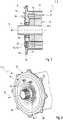
- An electrical machine 1, in particular an electric motor 2, as shown in the Figures 1 and 2 has a stator 3 and a rotor 4.
- a longitudinal section through the machine 1 in the region of an end cooling module 5 and in Figure 2 an isometric view of this area is shown.
- the stator 3 has a winding, not shown, through which an electrical current flows during operation and thus drives the rotor 4, which is at least partially paramagnetic.
- the rotor 4 is connected in a rotationally fixed manner to a shaft 6 or is produced in one piece with the shaft 6, which in the example shown is designed as a hollow shaft 7.
- the rotor 4 and the shaft 6 are rotatably mounted about an axis of rotation 8, the shaft 6 and the rotor 4 being arranged coaxially with the axis of rotation 8.
- the stator 3 surrounds the rotor 4 and is arranged coaxially to the rotor 4.
- the rotor 4 and the shaft 6 are supported by a bearing 9 which receives the shaft 6.
- the stator 3 has a winding head 10 protruding on the end face, which is completely enclosed on the outside in the circumferential direction by the cooling module 5, the circumferential direction being understood with respect to the axis of rotation 8.
- the cooling module 5 thus connects to the end of the stator 3 and the winding head 10.
- a balancing plate 11 is arranged radially on the inside of the winding head 10 and axially between the rotor 4 and the cooling module 5.
- the bearing 9 is accommodated in a bearing receptacle 20 of the cooling module 5 in the cooling module 5, so that the cooling module 5 is used to support the shaft 6 and thus the rotor 4 via the bearing 9.
- the cooling module 5 also serves to cool the electrical machine 1.
- the cooling module for this purpose has, on the side facing away from the stator 3, a channel section 12 which is open on the end and extends in the circumferential direction and is thus designed as an axially open recess 13 ,
- a cover 14 Cooling module 5 attached, which axially closes the channel section 12 or the recess 13 and thus forms a channel 15 with the cooling module 5, which in operation is flowed through by a cooling fluid, for example a cooling liquid, to the winding head 10 and thus via the cooling module 5 to cool the electrical machine 1.
- a cooling fluid for example a cooling liquid
- the stator 3, the rotor 4 and the shaft 6 are arranged in a housing 17 of the electrical machine 1.
- the cooling module 5 has radially projecting connecting sections 18 in the manner of a flange 19, via which the cooling module 5 and thus the stator 3, the rotor 4 and the shaft 6 are fastened to the housing 17.
- a mold not shown, is used, in which the winding head 10 of the stator 3 is arranged.
- the cooling module 5 is produced with the casting mold.
- the stator 3, the rotor 4, the shaft 6 and the bearing 9 can be prefabricated and then arranged with respect to the casting mold in such a way that after the cooling module 5 has been produced, the position shown relative to the cooling module 5 and to one another is obtained.
- a casting material which forms the cooling module 5 is then introduced into the casting mold, in particular cast and / or injection-molded, while a negative pressure, in particular a vacuum, is generated in the casting mold.
- the casting material is introduced in such a way that the casting material surrounds the winding head 10 and in particular fills cavities between windings of the winding head which are not shown.
- the casting material then hardens, so that the cooling module 5 is produced.
- the cooling module 5 is thus connected to the winding head 10 with an enlarged heat transfer surface, so that the winding head 10 and thus also the stator 3 are cooled in an improved manner.
- the cast material also surrounds the bearing 9 and forms the bearing receptacle 20, so that the cooling module 5 also positions the rotor 4 or the shaft 6 relative to the stator 3.
- the casting mold can furthermore have corresponding receptacles for removing the bearing 9 and / or the winding head 10.
- the casting mold is designed such that the cooling module 5 has the channel section 12 or the recess 13.
- the structural unit comprising the cooling module 5, stator 3, rotor 5, shaft 6, bearing 9 and, if appropriate, balancing shield 11 is removed from the casting mold and inserted into the housing 17 and via the connecting sections 18 of the cooling module 5 attached to the housing 17.
- the cover 14 can be attached to the cooling module 5 before or after this insertion.
- the cover 14 is advantageously produced as an injection molded part, for example made of plastic, the connecting pieces 16 being formed in the casting process and thus integrally with the cover 14.
Landscapes
- Engineering & Computer Science (AREA)
- Power Engineering (AREA)
- Manufacturing & Machinery (AREA)
- Motor Or Generator Cooling System (AREA)
- Manufacture Of Motors, Generators (AREA)
Abstract
Description
- Die vorliegende Erfindung betrifft ein Verfahren zum Herstellen einer elektrischen Maschine. Die Erfindung betrifft des Weiteren eine derartig hergestellte elektrische Maschine.
- Elektrische Maschinen, insbesondere Elektromotoren, weisen in der Regel einen Stator mit im Betrieb stromdurchflossenen Wicklungen auf, der einen stirnseitig abstehenden Wickelkopf aufweist. Die Maschine weist zudem einen Rotor auf, der üblicherweise vom Stator umschlossen ist und mit Hilfe des Stators in Rotation versetzt wird. Solche elektrische Maschinen weisen gewöhnlich ein Gehäuse auf, in dem der Stator und der Rotor aufgenommen sind. Bekannt ist es, den Stator passgenau in das Gehäuse einzupressen. Im Betrieb derartiger Maschinen entsteht Wärme, die eine Leistungsbegrenzung der Maschine darstellt und/oder zur Beschädigungen der elektrischen Maschine führen kann. Es ist daher wünschenswert, derartige Maschinen zu kühlen, um besagte Beschädigungen zu vermeiden und/oder die Effizienz der elektrischen Maschine zu erhöhen.
- Das von der elektrischen Maschine erzeugte Moment wird gewöhnlich über den Rotor übertragen, der innerhalb der elektrischen Maschine gelagert ist. Dabei ist es wichtig, die Ausrichtung des Rotors relativ zum Stator möglichst genau einzustellen. Wird der Stator in das Gehäuse eingepresst, fordert die genaue relative Ausrichtung des Stators zum Rotor enge Toleranzen des Statoraußendurchmessers, des Gehäuseinnendurchmessers sowie eines Lagerflansches, in dem ein Lager zum Lagern des Rotors aufgenommen ist und der am Gehäuse fixiert ist und dieses insbesondere stirnseitig verschließt. Dies führt zu hohen Herstellungskosten der elektrischen Maschine. Weist das Gehäuse zudem Kühlfluid führende Kanäle auf, um die elektrische Maschine zu kühlen, führt dies, insbesondere auch durch die eng einzuhaltenden Toleranzen, zu weiteren Kostensteigerungen der Herstellung der elektrischen Maschine.
- Aus der
EP 1 587 204 A2 ist es bekannt, den Lagerflansch einer elektrischen Maschine über den Stator zu lagern. Somit können das Gehäuse und der Stator mit höheren Toleranzen hergestellt und die Herstellungskosten somit reduziert werden. - Aus der
EP 1 199 787 A1 ist es bekannt, eine elektrische Maschine über den Wickelkopf zu kühlen. - Die vorliegende Erfindung beschäftigt sich mit der Aufgabe, für ein Verfahren zum Herstellen einer elektrischen Maschine der eingangs genannten Art sowie für eine solche elektrische Maschine verbesserte oder zumindest andere Ausführungsformen anzugeben, die sich insbesondere durch eine kostengünstige Herstellung und/oder eine Effizienzsteigerung der elektrischen Maschine auszeichnen.
- Diese Aufgabe wird erfindungsgemäß durch die Gegenstände der unabhängigen Ansprüche gelöst. Vorteilhafte Ausführungsformen sind Gegenstand der abhängigen Ansprüche.
- Die vorliegende Erfindung beruht auf dem allgemeinen Gedanken, eine elektrische Maschine mit einem Kühlmodul zu versehen, das dem Kühlen der elektrischen Maschine dient, und das Kühlmodul um einen Wickelkopf eines Stators der elektrischen Maschine zu gießen. In der Folge erhöht sich die wärmeübertragende Fläche zwischen dem Wickelkopf und dem Kühlmodul, so dass eine effizientere Kühlung und somit eine Effizienzsteigerung der elektrischen Maschine erfolgt. Zudem kann hierdurch eine Relativpositionierung des Kühlmoduls zum Stator realisiert werden, so dass weitere mechanische Verbindungen zwischen dem Stator und dem Kühlmodul entfallen können. Insgesamt lässt sich die elektrische Maschine hierdurch kostengünstiger herstellen. Zudem weist die elektrische Maschine durch die verbesserte Kühlung eine erhöhte Effizienz auf.
- Dem Erfindungsgedanken entsprechend weist die elektrische Maschine den Stator auf, der den stirnseitig abstehenden Wickel kopf aufweist. Der Stator umfasst insbesondere Wicklungen, die sich im Wickelkopf fortsetzen. Die elektrische Maschine weist zudem einen Rotor auf, der im Betrieb vom Stator angetrieben ist.. Das Kühlmodul der elektrischen Maschine ist im Betrieb durch die Strömung eines Kühlfluids gekühlt und kühlt somit über den Wickelkopf die elektrische Maschine. Zum Herstellen der elektrischen Maschine wird der Stator mit dem Wickelkopf in einer Gussform angeordnet, mit der das Kühlmodul hergestellt wird. Zudem, insbesondere anschließend, wird ein Gussmaterial in die Gussform eingebracht, welches anschließend das Kühlmodul ausbildet. Insbesondere wird die Gussform mit dem Gussmaterial gefüllt. Das Einbringen des Gussmaterials in die Gussform erfolgt derart, dass das Gussmaterial und somit anschließend das Kühlmodul den Wickelkopf umschließt. Danach wird das somit hergestellte Kühlmodul, das heißt insbesondere nach dem Aushärten des Gussmaterials, zusammen mit dem Stator aus der Gussform entfernt. Insbesondere schließt das Kühlmodul stirnseitig am Stator an.
- Der Rotor kann prinzipiell beliebig ausgestaltet sein. Vorstellbar ist ein permanentmagnetischer Rotor. Denkbar sind auch Ausgestaltungen der elektrischen Maschine als Asynchronmaschine oder als Transversalflussmaschine.
- Das Gussmaterial ist zweckmäßig elektrisch isolierend. Vorteilhaft kommt als Gussmaterial ein Kunststoff zum Einsatz.
- Besonders bevorzugt erfolgt das Einbringen des Gussmaterials in die Gussform derart, dass das Gussmaterial den Wickelkopf, insbesondere die Hohlräume zwischen Wickelungen des Wickelkopfs, füllt. Hierdurch erfolgt eine weitere Vergrößerung der wärmeübertragenden Fläche zwischen dem Wickelkopf und dem Kühlmodul und in der Folge eine verbesserte Kühlung des Wickelkopfs und somit der elektrischen Maschine über das Kühlmodul.
- Vorteilhaft ist es, wenn die Gussform für den Wickelkopf eine zugehörige Aufnahme aufweist. Hierdurch kann eine genauere Relativpositionierung des Stators zum Kühlmodul erzielt werden und/oder die Herstellung des Kühlmoduls und somit der elektrischen Maschine vereinfacht werden.
- Vorteilhaft sind Ausführungsformen, bei denen in der Gussform ein Unterdruck erzeugt und das Gussmaterial in die Gussform eingebracht wird. Somit werden Lufteinschlüsse im Gussmaterial verhindert oder zumindest verringert, so dass auch das Kühlmodul keine oder zumindest reduzierte Lufteinschlüsse aufweist. Als Resultat erfolgt innerhalb des Kühlmoduls ein verbesserter Wärmetransport, so dass der Wickelkopf und somit die elektrische Maschine verbessert gekühlt wird. Dabei ist es insbesondere vorstellbar, in der Gussform ein Vakuum zu erzeugen und anschließend das Gussmaterial in die Gussform einzubringen.
- Das Eindringen des Gussmaterials in die Gussform kann auf beliebige Weise erfolgen. Insbesondere wird das Gussmaterial in die Gussform gegossen, beispielsweise spritzgegossen.
- Bei vorteilhaften Ausführungsformen ist die Gussform derart ausgebildet, dass das mit der Gussform hergestellte Kühlmodul auf der vom Wickelkopf abgewandten Seite einen stirnseitig offenen Kanalabschnitt oder eine Vertiefung aufweist. Die elektrische Maschine weist dabei eine Abdeckung auf, welche den Kanalabschnitt bzw. die Vertiefung verschließt und somit zusammen mit dem Kanalabschnitt einen Kanal bildet, der im Betrieb vom Kühlfluid durchströmt ist. Somit kann die Strömung des die elektrische Maschine kühlenden Kühlfluids, beispielsweise einer Kühlflüssigkeit, insbesondere von Kühlwasser, stirnseitig der elektrischen Maschine über das Kühlmodul und die Abdeckung erfolgen.
- Bevorzugt weist die Abdeckung zur Versorgung des Kanals mit dem Kühlfluid, das heißt zur Zuführung und/oder zur Abführung des Kühlfluids, wenigstens einen Stutzen auf. Somit sind keine weiteren Bestandteile zur fluidischen Versorgung der elektrischen Maschine mit dem Kühlfluid notwendig.
- Eine kostengünstige und vereinfachte Herstellung der elektrischen Maschine ergibt sich dadurch, dass die Abdeckung durch ein Spritzverfahren, insbesondere durch ein Spritzgussverfahren, vorteilhaft aus Kunststoff, hergestellt wird. Die Herstellung der Abdeckung erfolgt dabei zweckmäßig separat von der Herstellung des Kühlmoduls.
- Besonders bevorzugt sind Ausführungsformen, bei denen auch eine Lagerung des Rotors der elektrischen Maschine am Kühlmodul realisiert wird. Das Kühlmodul dient also einerseits der Lagerung des Rotors und andererseits der Kühlung der elektrischen Maschine. Durch die Lagerung des Rotors ist zudem durch das Kühlmodul auch eine Relativpositionierung des Stators zum Rotor vorgegeben.
- Vorteilhaft ist die Gussform derart ausgebildet, dass das mit der Gussform hergestellte Kühlmodul eine Lageraufnahme zum Aufnehmen eines Lagers zur Lagerung des Rotors aufweist. Vorstellbar ist es dabei, das Lager nach dem Herstellen des Kühlmoduls in das Kühlmodul einzusetzen. Denkbar sind Ausführungsformen, bei denen das Lager als ein Einlegeteil, insbesondere zusammen mit dem Rotor und/oder einer drehfest mit dem Rotor verbundenen Welle, in die Gussform eingelegt wird, bevor das Gussmaterial in die Gussform eingebracht wird.
- Nach dem Herstellen des Kühlmoduls kann dieses zusammen mit dem Stator als eine Baueinheit, die zudem den Rotor und/oder die Welle umfasst, in einem Gehäuse der elektrischen Maschine angeordnet werden, wobei eine Relativpositionierung des Stators zum Rotor über das Gehäuse entfällt.
- Es versteht sich, dass der Stator an beiden Stirnseiten jeweils einen Wickelkopf aufweisen kann, wobei am jeweiligen Wickelkopf ein solches Kühlmodul hergestellt/oder ausgebildet sein kann.
- Es versteht sich ferner, dass neben dem Verfahren zum Herstellen der elektrischen Maschine auch eine derartig hergestellte elektrische Maschine, insbesondere Elektromotor, zum Umfang dieser Erfindung gehört.
- Weitere wichtige Merkmale und Vorteile der Erfindung ergeben sich aus den Unteransprüchen, aus den Zeichnungen und aus der zugehörigen Figurenbeschreibung anhand der Zeichnungen.
- Es versteht sich, dass die vorstehend genannten und die nachstehend noch zu erläuternden Merkmale nicht nur in der jeweils angegebenen Kombination, sondern auch in anderen Kombinationen oder in Alleinstellung verwendbar sind, ohne den Rahmen der vorliegenden Erfindung zu verlassen.
- Bevorzugte Ausführungsbeispiele der Erfindung sind in den Zeichnungen dargestellt und werden in der nachfolgenden Beschreibung näher erläutert, wobei sich gleiche Bezugszeichen auf gleiche oder ähnliche oder funktional gleiche Komponenten beziehen.
- Es zeigen, jeweils schematisch
- Fig. 1
- einen Längsschnitt durch eine elektrische Maschine,
- Fig. 2
- eine isometrische Ansicht der elektrischen Maschine.
- Eine elektrische Maschine 1, insbesondere ein Elektromotor 2, wie sie in den
Figuren 1 und 2 gezeigt ist, weist einen Stator 3 sowie einen Rotor 4 auf. Dabei ist inFigur 1 ein Längsschnitt durch die Maschine 1 im Bereich eines stirnseitigen Kühlmoduls 5 und inFigur 2 eine isometrische Ansicht dieses Bereichs gezeigt. Der Stator 3 weist eine nicht gezeigte Wicklung auf, die im Betrieb von einem elektrischen Strom durchströmt ist und somit den Rotor 4, der zumindest teilweise paramagnetisch ausgebildet ist, antreibt. Der Rotor 4 ist drehfest mit einer Welle 6 verbunden oder einstückig mit der Welle 6 hergestellt, die im gezeigten Beispiel als eine Hohlwelle 7 ausgebildet ist. Der Rotor 4 und die Welle 6 sind um eine Drehachse 8 drehbar gelagert, wobei die Welle 6 und der Rotor 4 koaxial zur Drehachse 8 angeordnet sind. Der Stator 3 umgibt den Rotor 4 und ist koaxial zum Rotor 4 angeordnet. Die Lagerung des Rotors 4 und der Welle 6 erfolgt über ein Lager 9, welches die Welle 6 aufnimmt. Der Stator 3 weist einen stirnseitig abstehenden Wickelkopf 10 auf, der außenseitig vom Kühlmodul 5 in Umfangsrichtung gänzlich umschlossen ist, wobei die Umfangsrichtung bezüglich der Rotationsachse 8 zu verstehen ist. Das Kühlmodul 5 schließt somit stirnseitig am Stator 3 und am Wickelkopf 10 an. Radial innenseitig des Wickelkopfs 10 und axial zwischen dem Rotor 4 und dem Kühlmodul 5 ist ein Wuchtschild 11 angeordnet. Das Lager 9 ist in einer Lageraufnahme 20 des Kühlmoduls 5 im Kühlmodul 5 aufgenommen, so dass das Kühlmodul 5 zum Lagern der Welle 6 und somit des Rotors 4 über das Lager 9 zum Einsatz kommt. Das Kühlmodul 5 dient zudem der Kühlung der elektrischen Maschine 1. Im gezeigten Beispiel weist das Kühlmodul hierzu auf der vom Stator 3 abgewandten Seite einen stirnseitig nach außen offenen, sich in Umfangsrichtung erstreckenden Kanalabschnitt 12 auf, die somit als eine axial offene Vertiefung 13 ausgebildet ist. Auf der vom Stator 3 abgewandten Seite des Kühlmoduls 5 ist eine Abdeckung 14 am Kühlmodul 5 angebracht, die den Kanalabschnitt 12 bzw. die Vertiefung 13 axial verschließt und somit mit dem Kühlmodul 5 einen Kanal 15 bildet, der im Betrieb von einem Kühlfluid, beispielsweise einer Kühlflüssigkeit, durchströmt ist, um über das Kühlmodul 5 den Wickelkopf 10 und somit die elektrische Maschine 1 zu kühlen. An der Abdeckung 14 sind zwei Stutzen 16 integral ausgeformt, mit denen eine Versorgung des Kanals15 mit dem Kühlfluid, das heißt eine Zuführung und eine Abführung des Kühlfluids, erfolgt. Der Stator 3, der Rotor 4 sowie die Welle 6 sind in einem Gehäuse 17 der elektrischen Maschine 1 angeordnet. Das Kühlmodul 5 weist radial abstehende Verbindungsabschnitte 18 in der Art eines Flansches 19 auf, über welche das Kühlmodul 5 und somit der Stator 3, der Rotor 4 und die Welle 6 am Gehäuse 17 befestigt sind. - Zum Herstellen der elektrischen Maschine 1 kommt eine nicht gezeigte Gussform zum Einsatz, in welcher der Wickelkopf 10 des Stators 3 angeordnet wird. Mit der Gussform wird das Kühlmodul 5 hergestellt. Dabei können der Stator 3, der Rotor 4, die Welle 6 und das Lager 9 vorgefertigt und anschließend derart bezüglich der Gussform angeordnet werden, dass sich nach dem Herstellen des Kühlmoduls 5 die gezeigte Relativpositionierung zum Kühlmodul 5 und zueinander ergibt. Zum Herstellen des Kühlmoduls 5 wird anschließend ein das Kühlmodul 5 ausbildendes Gussmaterial in die Gussform eingebracht, insbesondere gegossen und/oder spritzgegossen, während in der Gussform ein Unterdruck, insbesondere ein Vakuum, erzeugt wird. Das Einbringen des Gussmaterials erfolgt derart, dass das Gussmaterial den Wickelkopf 10 umgibt und insbesondere Hohlräume zwischen nicht gezeigten Wicklungen des Wickelkopfs füllt. Anschließend härtet das Gussmaterial aus, so dass das Kühlmodul 5 hergestellt ist. Das Kühlmodul 5 ist somit mit einer vergrößerten wärmeübertragenden Fläche mit dem Wickelkopf 10 verbunden, so dass der Wickelkopf 10 und somit auch der Stator 3 verbessert gekühlt werden. Das Gussmaterial umgibt zudem das Lager 9 und bildet die Lageraufnahme 20 aus, so dass mit dem Kühlmodul 5 zudem eine Relativpositionierung des Rotors 4 bzw. der Welle 6 zum Stator 3 erfolgt. Die Gussform kann ferner zum Ausnehmen des Lagers 9 und/oder des Wickelkopfs 10 entsprechende Aufnahmen aufweisen. Zudem ist die Gussform derart ausgebildet, dass das Kühlmodul 5 den Kanalabschnitt 12 bzw. die Vertiefung 13 aufweist. Nach dem Herstellen des Kühlmoduls, insbesondere nach dem Aushärten des Gussmaterials, wird die Baueinheit aus Kühlmodul 5, Stator 3, Rotor 5, Welle 6, Lager 9 und gegebenenfalls Wuchtschild 11 aus der Gussform entfernt und in das Gehäuse 17 eingeschoben und über die Verbindungsabschnitte 18 des Kühlmoduls 5 am Gehäuse 17 befestigt. Das Anbringen der Abdeckung 14 am Kühlmodul 5 kann vor oder nach diesem Einschieben erfolgen.
- Die Abdeckung 14 ist vorteilhaft als ein Spritzgussteil, beispielsweise aus Kunststoff, hergestellt, wobei die Stutzen 16 im Gussverfahren und somit integral mit der Abdeckung 14 ausgebildet werden.
Claims (10)
- Verfahren zum Herstellen einer elektrischen Maschine (1), die aufweist:- einen Stator (3) mit einem stirnseitig abstehenden Wickelkopf (10), sowie- einen Rotor (4), und- ein den Wickelkopf (10) umschließendes Kühlmodul (5), das im Betrieb durch die Strömung eines Kühlfluids die elektrische Maschine (1) kühlt,dadurch gekennzeichnet,- dass der Wickelkopf (10) des Stators (3) in einer Gussform zum Herstellen des Kühlmoduls (5) angeordnet wird,- dass in die Gussform zum Herstellen des Kühlmoduls (5) ein das Kühlmodul (5) ausbildendes Gussmaterial eingebracht wird, derart, dass das Gussmaterial den Wickelkopf (10) umschließt,- dass das somit hergestellte Kühlmodul (5) zusammen mit dem Stator (3) aus der Gussform entfernt wird.
- Verfahren nach Anspruch 1,
dadurch gekennzeichnet,
dass eine Gussform bereitgestellt wird, die für den Wickelkopf (10) eine zugehörige Aufnahme aufweist. - Verfahren nach Anspruch 1 oder 2,
dadurch gekennzeichnet,
dass in der Gussform ein Unterdruck erzeugt und das Gussmaterial in die Gussform eingebracht wird. - Verfahren nach einem der Ansprüche 1 bis 3,
dadurch gekennzeichnet,
dass das Gussmaterial in die Gussform gegossen wird. - Verfahren nach einem der Ansprüche 1 bis 4,
dadurch gekennzeichnet,- dass eine Gussform bereitgestellt wird, die derart ausgebildet ist, dass das Kühlmodul (5) auf der vom Wickelkopf (10) abgewandten Seite einen stirnseitig offenen Kanalabschnitt (12) aufweist,- dass der Kanalabschnitt (12) mit einer Abdeckung (14) verschlossen wird, die zusammen mit dem Kanalabschnitt (12) einen vom Kühlfluid durchströmten Kanal (15) bildet. - Verfahren nach Anspruch 5,
dadurch gekennzeichnet,
dass die Abdeckung (14) mit zumindest einem Stutzen (16) zur Versorgung des Kanals (15) mit dem Kühlfluid versehen wird. - Verfahren nach Anspruch 5 oder 6,
dadurch gekennzeichnet,
dass die Abdeckung (14) durch ein Spritzverfahren hergestellt wird. - Verfahren nach einem der Ansprüche 1 bis 7,
dadurch gekennzeichnet,
dass eine Gussform bereitgestellt wird, die derart ausgebildet ist, dass das Kühlmodul (5) eine Lageraufnahme (20) zum Aufnehmen eines Lagers (9) zur Lagerung des Rotors (4) aufweist. - Verfahren nach einem der Ansprüche 1 bis 8,
dadurch gekennzeichnet,
dass der Stator (3) mit dem vom Kühlmodul (5) umschlossenen Wickelkopf (10) in ein Gehäuse (17) der elektrischen Maschine (1) angeordnet wird. - Elektrische Maschine (1), insbesondere Elektromotor (2), mit- einem Stator (3), der einen stirnseitig abstehenden Wickelkopf (10) aufweist,- einem Rotor (4), der vom Stator (3) umgeben ist,- einem den Wickelkopf (10) umschließenden Kühlmodul (5), das im Betrieb durch die Strömung eines Kühlfluids die elektrische Maschine (1) kühlt,wobei die elektrische Maschine (1) gemäß dem Verfahren nach einem der Ansprüche 1 bis 9 hergestellt ist.
Applications Claiming Priority (1)
| Application Number | Priority Date | Filing Date | Title |
|---|---|---|---|
| DE102018214282.3A DE102018214282A1 (de) | 2018-08-23 | 2018-08-23 | Verfahren zum Herstellen einer elektrischen Maschine |
Publications (1)
| Publication Number | Publication Date |
|---|---|
| EP3614537A1 true EP3614537A1 (de) | 2020-02-26 |
Family
ID=67587680
Family Applications (1)
| Application Number | Title | Priority Date | Filing Date |
|---|---|---|---|
| EP19191106.4A Withdrawn EP3614537A1 (de) | 2018-08-23 | 2019-08-09 | Verfahren zum herstellen einer elektrischen maschine |
Country Status (2)
| Country | Link |
|---|---|
| EP (1) | EP3614537A1 (de) |
| DE (1) | DE102018214282A1 (de) |
Citations (7)
| Publication number | Priority date | Publication date | Assignee | Title |
|---|---|---|---|---|
| EP1199787A1 (de) | 2000-10-17 | 2002-04-24 | Mitsubishi Denki Kabushiki Kaisha | Wechselstromgenerator für Fahrzeuge mit Kühlung der Stator-Wickelköpfe |
| EP1587204A2 (de) | 2004-04-16 | 2005-10-19 | Fanuc Ltd | Elektromotor |
| US20070273225A1 (en) * | 2003-11-20 | 2007-11-29 | Philip Head | Electric Motors for Powering Downhole Tools |
| US20110304228A1 (en) * | 2010-06-14 | 2011-12-15 | Bradfield Michael D | Potted End Turns of an Electric Machine |
| US20150171689A1 (en) * | 2013-12-16 | 2015-06-18 | Fanuc Corporation | Motor, production method for motor and turbo-blower apparatus |
| US20180175707A1 (en) * | 2015-06-09 | 2018-06-21 | Mitsubishi Electric Corporation | Rotary electric machine |
| DE102017011828A1 (de) * | 2017-12-21 | 2018-06-28 | Daimler Ag | Verfahren zur Herstellung einer Wickelkopfkühlung eines Wickelkopfs sowie Gusswerkzeug zur Herstellung einer Wickelkopfkühlung |
Family Cites Families (2)
| Publication number | Priority date | Publication date | Assignee | Title |
|---|---|---|---|---|
| JP4586542B2 (ja) * | 2005-01-17 | 2010-11-24 | トヨタ自動車株式会社 | 回転電機 |
| US20140009013A1 (en) * | 2012-07-06 | 2014-01-09 | Remy Technologies, Llc | Stator torque retention feature for a cast-in stator assembly |
-
2018
- 2018-08-23 DE DE102018214282.3A patent/DE102018214282A1/de not_active Withdrawn
-
2019
- 2019-08-09 EP EP19191106.4A patent/EP3614537A1/de not_active Withdrawn
Patent Citations (7)
| Publication number | Priority date | Publication date | Assignee | Title |
|---|---|---|---|---|
| EP1199787A1 (de) | 2000-10-17 | 2002-04-24 | Mitsubishi Denki Kabushiki Kaisha | Wechselstromgenerator für Fahrzeuge mit Kühlung der Stator-Wickelköpfe |
| US20070273225A1 (en) * | 2003-11-20 | 2007-11-29 | Philip Head | Electric Motors for Powering Downhole Tools |
| EP1587204A2 (de) | 2004-04-16 | 2005-10-19 | Fanuc Ltd | Elektromotor |
| US20110304228A1 (en) * | 2010-06-14 | 2011-12-15 | Bradfield Michael D | Potted End Turns of an Electric Machine |
| US20150171689A1 (en) * | 2013-12-16 | 2015-06-18 | Fanuc Corporation | Motor, production method for motor and turbo-blower apparatus |
| US20180175707A1 (en) * | 2015-06-09 | 2018-06-21 | Mitsubishi Electric Corporation | Rotary electric machine |
| DE102017011828A1 (de) * | 2017-12-21 | 2018-06-28 | Daimler Ag | Verfahren zur Herstellung einer Wickelkopfkühlung eines Wickelkopfs sowie Gusswerkzeug zur Herstellung einer Wickelkopfkühlung |
Also Published As
| Publication number | Publication date |
|---|---|
| DE102018214282A1 (de) | 2020-02-27 |
Similar Documents
| Publication | Publication Date | Title |
|---|---|---|
| DE102019127583A1 (de) | Rotoreinrichtung und Verfahren zur Herstellung einer Rotoreinrichtung für eine elektrische Maschine, insbesondere für einen Fahrzeugantrieb für ein Elektrofahrzeug | |
| DE102006062747A1 (de) | Elektrische Maschine | |
| DE102009038691A1 (de) | Elektrische Maschine | |
| WO2020035240A1 (de) | Rotor für fremderregte innenläufer-synchronmaschine, innenläufer-synchronmaschine, kraftfahrzeug sowie verfahren | |
| DE102011010489A1 (de) | Wachsausschmelzgießen von Induktionsmotorrotoren | |
| EP2422432B1 (de) | Kurzschlussläufer mit gegossenen kurzschlussstäben | |
| DE102021002941A1 (de) | Polelement zum Bereitstellen eines elektrischen Pols einer Axialflussmaschine | |
| AT521063A2 (de) | Stator | |
| EP3484018A1 (de) | Ec-motor mit vergossener ankerwelle | |
| DE2904384C2 (de) | Gehäuse für sich im wesentlichen axial erstreckende rotierende Maschinen, insbesondere für Elektromotoren und mehrstufige Pumpen | |
| DE102007039186A1 (de) | Läufer eines Traktionsmotors | |
| EP3114754B1 (de) | Elektrische maschine, beispielsweise für ein stromerzeugungsaggregat | |
| DE102006029803A1 (de) | Verfahren zum Herstellen einer elektrischen Maschine sowie elektrische Maschine, hergestellt nach diesem Verfahren | |
| DE102008003784A1 (de) | Vorrichtung und Verfahren zum Vollverguss von Statoren von Elektromotoren | |
| DE102017215835A1 (de) | Fluidgekühlte elektrische Maschine | |
| DE2630045A1 (de) | Verfahren zur herstellung von elektrischen maschinen | |
| DE102017011828A1 (de) | Verfahren zur Herstellung einer Wickelkopfkühlung eines Wickelkopfs sowie Gusswerkzeug zur Herstellung einer Wickelkopfkühlung | |
| DE4021591C2 (de) | ||
| DE102007014352A1 (de) | Verfahren zum Gießen eines einen Stator formschlüssig und spielfrei zumindest bereichsweise aufnehmenden Gehäuseelements für eine elektrische Maschine und entsprechende elektrische Maschine | |
| DE102011108042A1 (de) | Stator für eine elektrische Maschine und Verfahren zu dessen Herstellung | |
| EP3364525A1 (de) | Fertigung funktioneller einheiten elektrischer maschinen durch generative fertigungsverfahren | |
| DE102021115421B3 (de) | Verfahren und Vorrichtung zur Herstellung einer Statoreinrichtung für eine elektrische Maschine, insbesondere für eine Antriebsmaschine eines Elektrofahrzeugs | |
| WO2006066740A1 (de) | Elektrische maschine | |
| EP3355444B1 (de) | Rotor für eine elektrische maschine, elektrische maschine, insbesondere asynchronmaschine, für ein kraftfahrzeug und kraftfahrzeug | |
| DE102018214282A1 (de) | Verfahren zum Herstellen einer elektrischen Maschine |
Legal Events
| Date | Code | Title | Description |
|---|---|---|---|
| PUAI | Public reference made under article 153(3) epc to a published international application that has entered the european phase |
Free format text: ORIGINAL CODE: 0009012 |
|
| STAA | Information on the status of an ep patent application or granted ep patent |
Free format text: STATUS: THE APPLICATION HAS BEEN PUBLISHED |
|
| AK | Designated contracting states |
Kind code of ref document: A1 Designated state(s): AL AT BE BG CH CY CZ DE DK EE ES FI FR GB GR HR HU IE IS IT LI LT LU LV MC MK MT NL NO PL PT RO RS SE SI SK SM TR |
|
| AX | Request for extension of the european patent |
Extension state: BA ME |
|
| RIN1 | Information on inventor provided before grant (corrected) |
Inventor name: ESTEVES ALBIERI, GUSTAVO Inventor name: FRITSCH, KARL-MARTIN Inventor name: GRELLE, THORSTEN Inventor name: SCHMUELLING, DR., CHRISTOPH |
|
| STAA | Information on the status of an ep patent application or granted ep patent |
Free format text: STATUS: REQUEST FOR EXAMINATION WAS MADE |
|
| 17P | Request for examination filed |
Effective date: 20200813 |
|
| RBV | Designated contracting states (corrected) |
Designated state(s): AL AT BE BG CH CY CZ DE DK EE ES FI FR GB GR HR HU IE IS IT LI LT LU LV MC MK MT NL NO PL PT RO RS SE SI SK SM TR |
|
| STAA | Information on the status of an ep patent application or granted ep patent |
Free format text: STATUS: EXAMINATION IS IN PROGRESS |
|
| 17Q | First examination report despatched |
Effective date: 20210209 |
|
| STAA | Information on the status of an ep patent application or granted ep patent |
Free format text: STATUS: THE APPLICATION IS DEEMED TO BE WITHDRAWN |
|
| 18D | Application deemed to be withdrawn |
Effective date: 20230301 |