EP3614525A1 - Uninterruptible power supply and method of operating the same - Google Patents
Uninterruptible power supply and method of operating the same Download PDFInfo
- Publication number
- EP3614525A1 EP3614525A1 EP19150378.8A EP19150378A EP3614525A1 EP 3614525 A1 EP3614525 A1 EP 3614525A1 EP 19150378 A EP19150378 A EP 19150378A EP 3614525 A1 EP3614525 A1 EP 3614525A1
- Authority
- EP
- European Patent Office
- Prior art keywords
- power source
- unit
- input
- energy storage
- output
- Prior art date
- Legal status (The legal status is an assumption and is not a legal conclusion. Google has not performed a legal analysis and makes no representation as to the accuracy of the status listed.)
- Granted
Links
Images


Classifications
-
- H—ELECTRICITY
- H02—GENERATION; CONVERSION OR DISTRIBUTION OF ELECTRIC POWER
- H02J—ELECTRIC POWER NETWORKS; CIRCUIT ARRANGEMENTS OR SYSTEMS FOR SUPPLYING OR DISTRIBUTING ELECTRIC POWER; SYSTEMS FOR STORING ELECTRIC ENERGY
- H02J9/00—Circuit arrangements for emergency or stand-by power supply, e.g. for emergency lighting
- H02J9/04—Circuit arrangements for emergency or stand-by power supply, e.g. for emergency lighting in which the distribution system is disconnected from the normal source and connected to a standby source
- H02J9/06—Circuit arrangements for emergency or stand-by power supply, e.g. for emergency lighting in which the distribution system is disconnected from the normal source and connected to a standby source with automatic change-over, e.g. UPS systems
- H02J9/061—Circuit arrangements for emergency or stand-by power supply, e.g. for emergency lighting in which the distribution system is disconnected from the normal source and connected to a standby source with automatic change-over, e.g. UPS systems for DC powered loads
-
- H—ELECTRICITY
- H02—GENERATION; CONVERSION OR DISTRIBUTION OF ELECTRIC POWER
- H02J—ELECTRIC POWER NETWORKS; CIRCUIT ARRANGEMENTS OR SYSTEMS FOR SUPPLYING OR DISTRIBUTING ELECTRIC POWER; SYSTEMS FOR STORING ELECTRIC ENERGY
- H02J7/00—Circuit arrangements for charging or discharging batteries or for supplying loads from batteries
- H02J7/865—Battery or charger load switching, e.g. concurrent charging and load supply
-
- H—ELECTRICITY
- H02—GENERATION; CONVERSION OR DISTRIBUTION OF ELECTRIC POWER
- H02J—ELECTRIC POWER NETWORKS; CIRCUIT ARRANGEMENTS OR SYSTEMS FOR SUPPLYING OR DISTRIBUTING ELECTRIC POWER; SYSTEMS FOR STORING ELECTRIC ENERGY
- H02J9/00—Circuit arrangements for emergency or stand-by power supply, e.g. for emergency lighting
- H02J9/04—Circuit arrangements for emergency or stand-by power supply, e.g. for emergency lighting in which the distribution system is disconnected from the normal source and connected to a standby source
- H02J9/06—Circuit arrangements for emergency or stand-by power supply, e.g. for emergency lighting in which the distribution system is disconnected from the normal source and connected to a standby source with automatic change-over, e.g. UPS systems
- H02J9/062—Circuit arrangements for emergency or stand-by power supply, e.g. for emergency lighting in which the distribution system is disconnected from the normal source and connected to a standby source with automatic change-over, e.g. UPS systems for AC powered loads
-
- H—ELECTRICITY
- H02—GENERATION; CONVERSION OR DISTRIBUTION OF ELECTRIC POWER
- H02M—APPARATUS FOR CONVERSION BETWEEN AC AND AC, BETWEEN AC AND DC, OR BETWEEN DC AND DC, AND FOR USE WITH MAINS OR SIMILAR POWER SUPPLY SYSTEMS; CONVERSION OF DC OR AC INPUT POWER INTO SURGE OUTPUT POWER; CONTROL OR REGULATION THEREOF
- H02M3/00—Conversion of DC power input into DC power output
- H02M3/02—Conversion of DC power input into DC power output without intermediate conversion into AC
- H02M3/04—Conversion of DC power input into DC power output without intermediate conversion into AC by static converters
-
- H—ELECTRICITY
- H02—GENERATION; CONVERSION OR DISTRIBUTION OF ELECTRIC POWER
- H02J—ELECTRIC POWER NETWORKS; CIRCUIT ARRANGEMENTS OR SYSTEMS FOR SUPPLYING OR DISTRIBUTING ELECTRIC POWER; SYSTEMS FOR STORING ELECTRIC ENERGY
- H02J2207/00—Details of circuit arrangements for charging or discharging batteries or supplying loads from batteries
- H02J2207/10—Control circuit supply, e.g. means for supplying power to the control circuit
-
- H—ELECTRICITY
- H02—GENERATION; CONVERSION OR DISTRIBUTION OF ELECTRIC POWER
- H02J—ELECTRIC POWER NETWORKS; CIRCUIT ARRANGEMENTS OR SYSTEMS FOR SUPPLYING OR DISTRIBUTING ELECTRIC POWER; SYSTEMS FOR STORING ELECTRIC ENERGY
- H02J2207/00—Details of circuit arrangements for charging or discharging batteries or supplying loads from batteries
- H02J2207/20—Charging or discharging characterised by the power electronics converter
-
- H—ELECTRICITY
- H02—GENERATION; CONVERSION OR DISTRIBUTION OF ELECTRIC POWER
- H02J—ELECTRIC POWER NETWORKS; CIRCUIT ARRANGEMENTS OR SYSTEMS FOR SUPPLYING OR DISTRIBUTING ELECTRIC POWER; SYSTEMS FOR STORING ELECTRIC ENERGY
- H02J7/00—Circuit arrangements for charging or discharging batteries or for supplying loads from batteries
- H02J7/02—Circuit arrangements for charging or discharging batteries or for supplying loads from batteries for charging batteries from AC mains by converters
Definitions
- the present disclosure relates to an uninterruptible power supply and a method of operating the same, and more particularly to an uninterruptible power supply having less circuit components.
- the uninterruptible power supply 100A includes a switching unit 10A, a charging unit 20A, an energy storage unit 30A, a conversion unit 40A, a switching power supply SPS, and a control unit 50A.
- the charging unit 20A receives the input power source Vin and converts the input power source Vin to charge the energy storage unit 30A.
- the switching power supply SPS receives the power source outputted from the charging unit 20A and converts the power source outputted from the charging unit 20A to supply the control unit 50A.
- the switching power supply SPS receives the power source outputted from the energy storage unit 30A and converts the power source outputted from the energy storage unit 30A to supply the control unit 50A.
- a further conversion stage i.e., the switching power supply SPS is necessary to be used between the energy storage unit 30A and the control unit 50A so as to provide a stable working power source that meets the normal operation requirements of the control unit 50A.
- the volume and the circuit costs of the uninterruptible power supply cannot be reduced as well as the conversion losses increases and the efficiency reduces due to the further conversion stage.
- the uninterruptible power supply includes an input end receiving an input power source and an output end coupled to a load.
- the uninterruptible power supply includes a switching unit, a charging unit, an energy storage unit, a conversion unit, and a control unit.
- the switching unit is coupled to the input end and the output end.
- the charging unit is coupled to the input end.
- the energy storage unit is coupled to the charging unit.
- the conversion unit is coupled to the charging unit, the energy storage unit, and the output end.
- the control unit is coupled to the charging unit.
- the switching unit switches the input power source into a first output power source and provides the first power source to the output end, and the charging unit converts the input power source into a first power source and provides the first power source to the control unit and to charge the energy storage unit.
- the conversion unit converts the electricity of the energy storage unit into a second output power source and provide the second output power source to the output end, and the conversion unit provides a second power source to the charging unit and the charging unit converts the second power source into the first power source and provides the first power source to the control unit.
- the present disclosure provides a method of operating an uninterruptible power supply.
- the uninterruptible power supply receives an input power source and provides a first output power source or a second output power source to a load.
- the uninterruptible power supply includes a switching unit, a charging unit, an energy storage unit, a conversion unit, and a control unit.
- the method includes the steps of: switching, by the switching unit, the input power source into the first output power source when the input power source is available; converting, by the charging unit, the input power source into a first power source and providing the first power source to the control unit and to charge the energy storage unit when the input power source is available; converting, by the conversion unit, the electricity of the energy storage unit into a second output power source when the input power source is not available, and converting, by the conversion unit, the electricity of the energy storage unit into a second power source and providing the second power source to the charging unit, and converting, by the charging unit, the second power source into a first power source and providing the first power source to the control unit when the input power source is not available.
- the uninterruptible power supply 100 has an input end 100-1 and an output end 100-2, and the input end 100-1 receives an input power source Vin and the output end 100-2 is coupled to a load 200.
- the uninterruptible power supply 100 includes a switching unit 10, a charging unit 20, an energy storage unit 30, a conversion unit 40, and a control unit 50.
- One end of the switching unit 10 is coupled to the input end 100-1 and the other end of the switching unit 10 is coupled to the output end 100-2.
- One end of the charging unit 20 is coupled to the input end 100-1 and the other end of the charging unit 20 is coupled to the energy storage unit 30 and the control unit 50.
- a first end of the conversion unit 40 is coupled to the output end 100-2 and a second end of the conversion unit 40 is coupled to the energy storage unit 30.
- a third end of the conversion unit 40 is coupled to the charging unit 20 and provides a second power source V2 to the charging unit 20.
- the switching unit 10 receives the input power source Vin and provides a first output power source Vo1 to the output end 100-2 according to the input power source Vin so that the uninterruptible power supply 100 provides the first output power source Vo1 for supplying the required electricity to the load 200.
- the charging unit 20 receives the input power source Vin, converts the input power source Vin into a first power source V1, and outputs the first power source V1 to charge the energy storage unit 30. Also, the first power source V1 outputted from the charging unit 20 is provided to the control unit 50 for supplying the required electricity to the control unit 50.
- a step-down circuit such as a low-dropout regulator (LDO) is required to receive the first power source V1 and step down the magnitude of the first power source V1 for properly supplying the controller 56.
- LDO low-dropout regulator
- the energy storage unit 30 When the input power source Vin is not available, the energy storage unit 30 provides an energy storage power source Vc to the conversion unit 40.
- the energy storage power source Vc is the electricity stored in the energy storage unit 30 when the input power source Vin is available.
- the conversion unit 40 converts the energy storage power source Vc into a second output power source Vo2 and provides the second output power source Vo2 to the output end 100-2 so that the uninterruptible power supply 100 provides the second output power source Vo2 for supplying the required electricity to the load 200.
- the conversion unit 40 provides the second power source V2 to the charging unit 20 through the third end of the conversion unit 40, and the charging unit 20 converts the second power source V2 into the first power source V1 and provides the first power source V1 to the control unit 50 for supplying the required electricity to the control unit 50.
- the uninterruptible power supply 100 further includes a switch unit 60, and one end of the switch unit 60 is coupled to the charging unit 20 and the other end of the switch unit 60 is coupled to the energy storage unit 30.
- the switch unit 60 detects that the input power source Vin is available, the switch unit 60 is turned on to make the first power source V1 charge the energy storage unit 30 through the switch unit 60.
- the switch unit 60 detects that the input power source Vin is not available, the switch unit 60 is turned off. At this condition, a path between the charging unit 20 and the energy storage unit 30 is disconnected so that the first power source V1 outputted from the charging unit 20 fails to charge the energy storage unit 30.
- it is to control whether the switch unit 60 is turned on by detecting whether the input power source Vin is available or not and providing a control signal by the control unit 50.
- the control unit 50 includes an isolation transformer 52, a communication unit 54, and a controller 56.
- the controller 56 is provided to control the uninterruptible power supply 100 normally operating. A user may set operation modes of the uninterruptible power supply 100 by the communication unit 54 or the uninterruptible power supply 100 is communicated with other electronic apparatuses through the communication unit 54.
- One end of the isolation transformer 52 is coupled to the charging unit 20 and the other end of the isolation transformer 52 is coupled to the communication unit 54 so that the first power source V1 provided from the charging unit 20 to the communication unit 54 through the isolation transformer 52 for supplying the required electricity to the communication unit 54.
- the controller 56 is coupled to the charging unit 20 so that the first power source V1 provided from the charging unit 20 for supplying the required electricity to the controller 56.
- the communication unit 54 is usually disposed outside the uninterruptible power supply 100, such as but not limited to the surface of an outer casing of the uninterruptible power supply 100.
- the isolation transformer 52 with electrical isolation between a primary side and a secondary side thereof is used to protect the user manipulating the uninterruptible power supply 100.
- the controller 56 is usually disposed inside the uninterruptible power supply 100 and provides control signals to control different circuit units of the uninterruptible power supply 100 being in the normal operation. In generally, an additional isolation transformer coupled to the controller 56 is not required since the controller 56 is hardly touched by the user. In practical applications, however, the additional isolation transformer may be used according to the actual requirement of using the uninterruptible power supply 100.
- the energy storage power source Vc is converted by the conversion stage, i.e., the conversion unit 40 and the charging unit 20 to stabilize a voltage value of the power source, i.e., the first power source V1 received by the control unit 50.
- the uninterruptible power supply 100 is an AC-in/AC-out uninterruptible power supply
- the switching unit 10 is a switch component.
- the switching unit 10 is turned on so that the input power source Vin is the first output power source Vo1, and the input power source Vin is provided to the load 200 through the output end 100-2.
- the switching unit 10 is turned off so that the energy storage power source Vc provided from the energy storage unit 30 is converted by the conversion unit 40 into the second output power source Vo2 to supply the load 200 through the output end 100-2. Accordingly, the load 200 can obtain the required power supply wherever the input power source Vin is available or not available.
- the charging unit 20 includes a first rectifying unit 22 and a first DC conversion unit 24.
- One end of the first rectifying unit 22 is coupled to the input end 100-1 and the other end of the first rectifying unit 22 is coupled to the first DC conversion unit 24.
- the first DC conversion unit 24 has a first input side 24-1, a first output side 24-2, and a first transformation component 24-3.
- the first input side 24-1 is coupled to the first rectifying unit 22 and the conversion unit 40, and the first output side 24-2 is coupled to the control unit 50 and coupled to the energy storage unit 30 through the switch unit 60.
- the first transformation component 24-3 is coupled between the first input side 24-1 and the first output side 24-2 to convert the electricity energy from the first input side 24-1 to the first output side 24-2 in an electromagnetic coupling manner.
- the first DC conversion unit 24 is a flyback converter for converting a power source with a high-voltage, such as but not limited to 180 volts into a power source with a low-voltage, such as but not limited to 12 volts, and the first transformation component 24-3 thereof is used to provide the electrical isolation between the high voltage and the low voltage. Therefore, different DC converters known in the art should be included in the scope of the present disclosure.
- the rectified input power source Vin is provided to the first input side 24-1 of the first DC conversion unit 24.
- the first DC conversion unit 24 converts the rectified input power source Vin into the first power source V1 and outputs the first power source V1 through the first output side 24-2.
- the first DC conversion unit 24 converts the second power source V2, which is produced by converting the energy storage power source Vc outputted form the energy storage unit 30 by the conversion unit 40, into the first power source V1 and outputs the first power source V1 through the first output side 24-2.
- the switch unit 60 When the input power source Vin is available, the switch unit 60 is turned on.
- the first DC conversion unit 24 converts the rectified input power source Vin into the first power source V1 and outputs the first power source V1 through the first output side 24-2.
- the first power source V1 is provided to the control unit 50 through the first output side 24-2 and provided to charge the energy storage unit 30 through the switch unit 60.
- the switch unit 60 When the input power source Vin is not available, the switch unit 60 is turned off so that a path between the first output side 24-2 and the energy storage unit 30 is disconnected.
- the first DC conversion unit 24 converts the second power source V2 into the first power source V1 and outputs the first power source V1 through the first output side 24-2.
- the first power source V1 is provided to the control unit 50 through the first output side 24-2 but fails to charge the energy storage unit 30.
- the conversion unit 40 includes a second DC conversion unit 42 and an inverter unit 44.
- the second DC conversion unit 42 has a second input side 42-1, a second output side 42-2, and a second transformation component 42-3.
- the second input side 42-1 is coupled to the energy storage unit 30, and the second output side 42-2, i.e., the third end of the conversion unit 40 shown in FIG. 1 , is coupled to one end of the inverter unit 44 and the first input side 24-1 of the first DC conversion unit 24.
- the other end of the inverter unit 44 is coupled to the output end 100-2.
- the second transformation component 42-3 is coupled between the second input side 42-1 and the second output side 42-2 to convert the electricity energy from the second input side 42-1 to the second output side 42-2 in an electromagnetic coupling manner.
- the second DC conversion unit 42 converts the energy storage power source Vc provided from the energy storage unit 30 into the second power source V2, and provides the second power source V2 to the first input side 24-1 and the inverter unit 44 through the second output side 42-2.
- the inverter unit 44 inverts the second power source V2 into the second output power source Vo2 and provides the second output power source Vo2 to the load 200 through the output end 100-2.
- a diode D1 is connected between the second output side 42-2 and the first input side 24-1 so that the power does not flow from the first input side 24-1 to the second output side 42-2.
- the second DC conversion unit 42 is a push-pull converter for converting a power source with a low-voltage, such as but not limited to 12 volts into a power source with a high-voltage, such as but not limited to 180 volts, and the second transformation component 42-3 thereof is used to provide the electrical isolation between the high voltage and the low voltage.
- a low-voltage such as but not limited to 12 volts
- a high-voltage such as but not limited to 180 volts
- different DC converters known in the art should be included in the scope of the present disclosure.
- the second DC conversion unit 42 further has a filtering component 42-4, expressed as a dash box, and the filtering component is, for example but not limited to, an inductor.
- the filtering component 42-4 is coupled between the second transformation component 42-3 and the second output side 42-2 and filters the second power source V2. If the filtering component 42-4 is absent, the second DC conversion unit 42 converts the direct-current energy storage power source Vc into a unipolar square-wave second power source V2, and the second output side 42-2 provides the unipolar square-wave second power source V2 to the first input side 24-1 and the inverter unit 44.
- the inverter unit 44 inverts the unipolar square-wave second power source V2 into a bipolar square-wave second output power source Vo2 and provides the bipolar square-wave second output power source Vo2 to the output end 100-2.
- the filtering component 42-4 filters the unipolar square-wave second power source V2 into a pulsating-DC-wave second power source V2 and provides the pulsating-DC-wave second power source V2 from the second output side 42-2 to the first input side 24-1 and the inverter unit 44.
- the inverter unit 44 inverts the pulsating-DC-wave second power source V2 into a sine-wave second output power source Vo2 and provides the sine-wave second output power source Vo2 to the output end 100-2. Therefore, the filtering component 42-4 of the second DC conversion unit 42 is used to increase the overall efficiency of the uninterruptible power supply 100.
- the uninterruptible power supply 100 is an AC-in/DC-out uninterruptible power supply
- the switching unit 10' is an AC-to-DC converter.
- the switching unit 10' converts the input power source Vin into the first output power source Vol' and provides the first output power source Vol' to the load 200 through the output end 100-2.
- the switching unit 10' does not work so that the energy storage power source Vc provided from the energy storage unit 30 is converted by the conversion unit 40' into the second output power source Vo2' to supply the load 200 through the output end 100-2.
- the switching unit 10' includes a second rectifying unit 12 and a third DC conversion unit 14.
- One end of the second rectifying unit 12 is coupled to the input end 100-1 and the other end of the second rectifying unit 12 is coupled to one end of the third DC conversion unit 14, and the other end of the third DC conversion unit 14 is coupled to the output end 100-2.
- the second rectifying unit 12 rectifies the input power source Vin into a third power source V3, and the third DC conversion unit 14 converts the third power source V3 into the first output power source Vol' and provides the first output power source Vol' to the output end 100-2.
- the type of the third DC conversion unit 14 is not limited, i.e., a DC converter known in the art should be included in the scope of the present disclosure.
- the conversion unit 40' includes a second DC conversion unit 42'.
- the second DC conversion unit 42' has a second input side 42-1, a second output side 42-2, and a second transformation component 42-3.
- the second input side 42-1 is coupled to the energy storage unit 30, and the second output side 42-2, i.e., the third end of the conversion unit 40 shown in FIG. 1 , is coupled to the output end 100-2 and the first input side 24-1 of the first DC conversion unit 24.
- the second transformation component 42-3 is coupled between the second input side 42-1 and the second output side 42-2 to convert the electricity energy from the second input side 42-1 to the second output side 42-2 in an electromagnetic coupling manner.
- the second DC conversion unit 42' converts the energy storage power source Vc into the second power source V2, and provides the second power source V2 to the first input side 24-1 through the second output side 42-2.
- the second DC conversion unit 42' takes the second power source V2 as the second output power source Vo2' and provides the second output power source Vo2' to the output end 100-2 for supplying the required electricity to the load 200.
- the circuit structure, connection relationship, and control manner of a charging unit 20 not mentioned in this embodiment are the same as those disclosed in FIG. 3A .
- the second DC conversion unit 42' is a flyback converter, and its circuit structure and circuit function are the same as those of the first DC conversion unit 24 of the charging unit 20 shown in FIG. 3A . Therefore, different DC converters known in the art should be included in the scope of the present disclosure.
- FIG. 4 shows a flowchart of a method of operating the uninterruptible power supply according to the present disclosure, and also refer to FIG. 2-FIG. 3B .
- the uninterruptible power supply 100 receives an input power source Vin and provides a first output power source Vo1 or a second output power source Vo2 to a load 200.
- the method of operating the uninterruptible power supply 100 includes the steps as follows. First, when the input power source Vin is available, a switching unit 10 provides a first output power source Vo1 (S100).
- the switching unit 10 When the uninterruptible power supply 100 is an AC-in/AC-out uninterruptible power supply and the input power source Vin is available, the switching unit 10 is turned on so that the input power source Vin is the first output power source Vo1, and the input power source Vin is provided to the load 200 through an output end 100-2.
- the switching unit 10' converts the input power source Vin into a first output power source Vol' and provides the first output power source Vol' to the load 200 through the output end 100-2.
- a charging unit 20 converts the input power source Vin into a first power source V1 and provides the first power source V1 to a control unit 50 and to charge an energy storage unit 30 (S120).
- the charging unit 20 includes a first rectifying unit 22 and a first DC conversion unit 24. After the first rectifying unit 22 rectifies the input power source Vin, the rectified input power source Vin is provided to a first input side 24-1 of the first DC conversion unit 24.
- the first DC conversion unit 24 converts the rectified input power source Vin into the first power source V1 and outputs the first power source V1 through a first output side 24-2.
- the first DC conversion unit 24 converts the rectified input power source Vin into the first power source V1 and outputs the first power source V1 through the first output side 24-2.
- the first power source V1 is provided to the control unit 50 through the first output side 24-2 and provided to charge the energy storage unit 30 through the switch unit 60.
- a conversion unit 40 converts the electricity of the energy storage unit 30 into a second output power source (S140).
- a second DC conversion unit 42 converts an energy storage power source Vc provided from the energy storage unit 30 into a second power source V2, and provides the second power source V2 to the first input side 24-1 and an inverter unit 44 through a second output side 42-2.
- the inverter unit 44 inverts the second power source V2 into the second output power source Vo2 and provides the second output power source Vo2 to the load 200 through the output end 100-2.
- a second DC conversion unit 42' converts the energy storage power source Vc into the second power source V2, and provides the second power source V2 to the first input side 24-1 through the second output side 42-2.
- the second DC conversion unit 42' takes the second power source V2 as the second output power source Vo2' and provides the second output power source Vo2' to the output end 100-2 for supplying the required electricity to the load 200.
- the conversion unit 40 converts the electricity of the energy storage unit 30 into the second power source V2, and provides the second power source V2 to the charging unit 20; the charging unit 20 converts the second power source V2 into the first power source V1, and provides the first power source V1 to the control unit 50 (S160).
- the first DC conversion unit 24 converts the second power source V2 into the first power source V1 and outputs the first power source V1 through the first output side 24-2.
- the first power source V1 is provided to the control unit 50 through the first output side 24-2.
Landscapes
- Engineering & Computer Science (AREA)
- Power Engineering (AREA)
- Business, Economics & Management (AREA)
- Emergency Management (AREA)
- Charge And Discharge Circuits For Batteries Or The Like (AREA)
- Stand-By Power Supply Arrangements (AREA)
- Inverter Devices (AREA)
- Dc-Dc Converters (AREA)
Abstract
Description
- The present disclosure relates to an uninterruptible power supply and a method of operating the same, and more particularly to an uninterruptible power supply having less circuit components.
- The statements in this section merely provide background information related to the present disclosure and do not necessarily constitute prior art.
- As the growing development of technology, the demand of power quality for electrical apparatuses is getting higher and higher. In order to ensure the safety of electrical apparatuses, the uninterruptible power supply is highly regarded. Also, in order to meet the demand of using the uninterruptible power supply, the cost reduction and volume reduction thereof are gradually developed.
- Please refer to
FIG. 1 , which shows a schematic block diagram of an uninterruptible power supply according to the related art. Theuninterruptible power supply 100A includes aswitching unit 10A, acharging unit 20A, anenergy storage unit 30A, aconversion unit 40A, a switching power supply SPS, and acontrol unit 50A. When an input power source Vin is available, thecharging unit 20A receives the input power source Vin and converts the input power source Vin to charge theenergy storage unit 30A. At this condition, the switching power supply SPS receives the power source outputted from thecharging unit 20A and converts the power source outputted from thecharging unit 20A to supply thecontrol unit 50A. When the input power source Vin is not available, the switching power supply SPS receives the power source outputted from theenergy storage unit 30A and converts the power source outputted from theenergy storage unit 30A to supply thecontrol unit 50A. - In general, a further conversion stage, i.e., the switching power supply SPS is necessary to be used between the
energy storage unit 30A and thecontrol unit 50A so as to provide a stable working power source that meets the normal operation requirements of thecontrol unit 50A. However, the volume and the circuit costs of the uninterruptible power supply cannot be reduced as well as the conversion losses increases and the efficiency reduces due to the further conversion stage. - In order to solve the above-mentioned problems, the present disclosure provides an uninterruptible power supply. The uninterruptible power supply includes an input end receiving an input power source and an output end coupled to a load. The uninterruptible power supply includes a switching unit, a charging unit, an energy storage unit, a conversion unit, and a control unit. The switching unit is coupled to the input end and the output end. The charging unit is coupled to the input end. The energy storage unit is coupled to the charging unit. The conversion unit is coupled to the charging unit, the energy storage unit, and the output end. The control unit is coupled to the charging unit. When the input power source is available, the switching unit switches the input power source into a first output power source and provides the first power source to the output end, and the charging unit converts the input power source into a first power source and provides the first power source to the control unit and to charge the energy storage unit. When the input power source is not available, the conversion unit converts the electricity of the energy storage unit into a second output power source and provide the second output power source to the output end, and the conversion unit provides a second power source to the charging unit and the charging unit converts the second power source into the first power source and provides the first power source to the control unit.
- In order to solve the above-mentioned problems, the present disclosure provides a method of operating an uninterruptible power supply. The uninterruptible power supply receives an input power source and provides a first output power source or a second output power source to a load. The uninterruptible power supply includes a switching unit, a charging unit, an energy storage unit, a conversion unit, and a control unit. The method includes the steps of: switching, by the switching unit, the input power source into the first output power source when the input power source is available; converting, by the charging unit, the input power source into a first power source and providing the first power source to the control unit and to charge the energy storage unit when the input power source is available; converting, by the conversion unit, the electricity of the energy storage unit into a second output power source when the input power source is not available, and converting, by the conversion unit, the electricity of the energy storage unit into a second power source and providing the second power source to the charging unit, and converting, by the charging unit, the second power source into a first power source and providing the first power source to the control unit when the input power source is not available.
- It is to be understood that both the foregoing general description and the following detailed description are exemplary, and are intended to provide further explanation of the present disclosure as claimed. Other advantages and features of the present disclosure will be apparent from the following description, drawings and claims.
- The present disclosure can be more fully understood by reading the following detailed description of the embodiment, with reference made to the accompanying drawings as follows:
-
FIG. 1 is a schematic block diagram of an uninterruptible power supply according to the related art. -
FIG. 2 is a schematic block diagram of an uninterruptible power supply according to the present disclosure. -
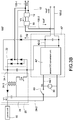
FIG. 3A is a circuit diagram of the uninterruptible power supply according to a first embodiment of the present disclosure. -
FIG. 3B is a circuit diagram of the uninterruptible power supply according to a second embodiment of the present disclosure. -
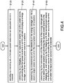
FIG. 4 is a flowchart of a method of operating the uninterruptible power supply according to the present disclosure. - Reference will now be made to the drawing figures to describe the present disclosure in detail. It will be understood that the drawing figures and exemplified embodiments of present disclosure are not limited to the details thereof.
- Please refer to
FIG. 2 , which shows a schematic block diagram of an uninterruptible power supply according to the present disclosure. Theuninterruptible power supply 100 has an input end 100-1 and an output end 100-2, and the input end 100-1 receives an input power source Vin and the output end 100-2 is coupled to aload 200. Theuninterruptible power supply 100 includes aswitching unit 10, acharging unit 20, anenergy storage unit 30, aconversion unit 40, and acontrol unit 50. One end of theswitching unit 10 is coupled to the input end 100-1 and the other end of theswitching unit 10 is coupled to the output end 100-2. One end of thecharging unit 20 is coupled to the input end 100-1 and the other end of thecharging unit 20 is coupled to theenergy storage unit 30 and thecontrol unit 50. A first end of theconversion unit 40 is coupled to the output end 100-2 and a second end of theconversion unit 40 is coupled to theenergy storage unit 30. In addition, a third end of theconversion unit 40 is coupled to thecharging unit 20 and provides a second power source V2 to thecharging unit 20. The detailed description of the connection between theconversion unit 40 and thecharging unit 20 and the opportunity of providing the second power source V2 will be made as follows. - When the input power source Vin is available, the
switching unit 10 receives the input power source Vin and provides a first output power source Vo1 to the output end 100-2 according to the input power source Vin so that theuninterruptible power supply 100 provides the first output power source Vo1 for supplying the required electricity to theload 200. At this condition, thecharging unit 20 receives the input power source Vin, converts the input power source Vin into a first power source V1, and outputs the first power source V1 to charge theenergy storage unit 30. Also, the first power source V1 outputted from thecharging unit 20 is provided to thecontrol unit 50 for supplying the required electricity to thecontrol unit 50. Moreover, if the magnitude of the first power source V1 is improper to supply thecontroller 56, for example, the magnitude of the first power source V1 is significantly greater than a working voltage of thecontroller 56, a step-down circuit, such as a low-dropout regulator (LDO) is required to receive the first power source V1 and step down the magnitude of the first power source V1 for properly supplying thecontroller 56. - When the input power source Vin is not available, the
energy storage unit 30 provides an energy storage power source Vc to theconversion unit 40. In particular, the energy storage power source Vc is the electricity stored in theenergy storage unit 30 when the input power source Vin is available. Theconversion unit 40 converts the energy storage power source Vc into a second output power source Vo2 and provides the second output power source Vo2 to the output end 100-2 so that theuninterruptible power supply 100 provides the second output power source Vo2 for supplying the required electricity to theload 200. At this condition, theconversion unit 40 provides the second power source V2 to thecharging unit 20 through the third end of theconversion unit 40, and thecharging unit 20 converts the second power source V2 into the first power source V1 and provides the first power source V1 to thecontrol unit 50 for supplying the required electricity to thecontrol unit 50. - The
uninterruptible power supply 100 further includes aswitch unit 60, and one end of theswitch unit 60 is coupled to thecharging unit 20 and the other end of theswitch unit 60 is coupled to theenergy storage unit 30. When theswitch unit 60 detects that the input power source Vin is available, theswitch unit 60 is turned on to make the first power source V1 charge theenergy storage unit 30 through theswitch unit 60. When theswitch unit 60 detects that the input power source Vin is not available, theswitch unit 60 is turned off. At this condition, a path between thecharging unit 20 and theenergy storage unit 30 is disconnected so that the first power source V1 outputted from thecharging unit 20 fails to charge theenergy storage unit 30. In one embodiment, it is to control whether theswitch unit 60 is turned on by detecting whether the input power source Vin is available or not and providing a control signal by thecontrol unit 50. - The
control unit 50 includes anisolation transformer 52, acommunication unit 54, and acontroller 56. Thecontroller 56 is provided to control theuninterruptible power supply 100 normally operating. A user may set operation modes of theuninterruptible power supply 100 by thecommunication unit 54 or theuninterruptible power supply 100 is communicated with other electronic apparatuses through thecommunication unit 54. One end of theisolation transformer 52 is coupled to the chargingunit 20 and the other end of theisolation transformer 52 is coupled to thecommunication unit 54 so that the first power source V1 provided from the chargingunit 20 to thecommunication unit 54 through theisolation transformer 52 for supplying the required electricity to thecommunication unit 54. Thecontroller 56 is coupled to the chargingunit 20 so that the first power source V1 provided from the chargingunit 20 for supplying the required electricity to thecontroller 56. Thecommunication unit 54 is usually disposed outside theuninterruptible power supply 100, such as but not limited to the surface of an outer casing of theuninterruptible power supply 100. Theisolation transformer 52 with electrical isolation between a primary side and a secondary side thereof is used to protect the user manipulating theuninterruptible power supply 100. Thecontroller 56 is usually disposed inside theuninterruptible power supply 100 and provides control signals to control different circuit units of theuninterruptible power supply 100 being in the normal operation. In generally, an additional isolation transformer coupled to thecontroller 56 is not required since thecontroller 56 is hardly touched by the user. In practical applications, however, the additional isolation transformer may be used according to the actual requirement of using theuninterruptible power supply 100. - Furthermore, when the input power source Vin is not available, the required electricity of the
control unit 50 and theload 200 is provided from theenergy storage unit 30. Since the electricity of theenergy storage unit 30 consumes continuously, a voltage value of the energy storage power source Vc gradually reduces. It would be possible that the reduction of the energy storage power source Vc fails to maintain thecontrol unit 50 normally working if the energy storage power source Vc provided from theenergy storage unit 30 directly supplies power to thecontrol unit 50. Therefore, the energy storage power source Vc is converted by the conversion stage, i.e., theconversion unit 40 and the chargingunit 20 to stabilize a voltage value of the power source, i.e., the first power source V1 received by thecontrol unit 50. - Please refer to
FIG. 3A , which shows a circuit diagram of the uninterruptible power supply according to a first embodiment of the present disclosure, and also refer toFIG. 2 . In one embodiment, theuninterruptible power supply 100 is an AC-in/AC-out uninterruptible power supply, and the switchingunit 10 is a switch component. When the input power source Vin is available, the switchingunit 10 is turned on so that the input power source Vin is the first output power source Vo1, and the input power source Vin is provided to theload 200 through the output end 100-2. When the input power source Vin is not available, the switchingunit 10 is turned off so that the energy storage power source Vc provided from theenergy storage unit 30 is converted by theconversion unit 40 into the second output power source Vo2 to supply theload 200 through the output end 100-2. Accordingly, theload 200 can obtain the required power supply wherever the input power source Vin is available or not available. - The charging
unit 20 includes afirst rectifying unit 22 and a firstDC conversion unit 24. One end of thefirst rectifying unit 22 is coupled to the input end 100-1 and the other end of thefirst rectifying unit 22 is coupled to the firstDC conversion unit 24. The firstDC conversion unit 24 has a first input side 24-1, a first output side 24-2, and a first transformation component 24-3. The first input side 24-1 is coupled to thefirst rectifying unit 22 and theconversion unit 40, and the first output side 24-2 is coupled to thecontrol unit 50 and coupled to theenergy storage unit 30 through theswitch unit 60. The first transformation component 24-3 is coupled between the first input side 24-1 and the first output side 24-2 to convert the electricity energy from the first input side 24-1 to the first output side 24-2 in an electromagnetic coupling manner. In one embodiment, the firstDC conversion unit 24 is a flyback converter for converting a power source with a high-voltage, such as but not limited to 180 volts into a power source with a low-voltage, such as but not limited to 12 volts, and the first transformation component 24-3 thereof is used to provide the electrical isolation between the high voltage and the low voltage. Therefore, different DC converters known in the art should be included in the scope of the present disclosure. - After the
first rectifying unit 22 rectifies the input power source Vin, the rectified input power source Vin is provided to the first input side 24-1 of the firstDC conversion unit 24. The firstDC conversion unit 24 converts the rectified input power source Vin into the first power source V1 and outputs the first power source V1 through the first output side 24-2. Alternatively, the firstDC conversion unit 24 converts the second power source V2, which is produced by converting the energy storage power source Vc outputted form theenergy storage unit 30 by theconversion unit 40, into the first power source V1 and outputs the first power source V1 through the first output side 24-2. - When the input power source Vin is available, the
switch unit 60 is turned on. The firstDC conversion unit 24 converts the rectified input power source Vin into the first power source V1 and outputs the first power source V1 through the first output side 24-2. The first power source V1 is provided to thecontrol unit 50 through the first output side 24-2 and provided to charge theenergy storage unit 30 through theswitch unit 60. - When the input power source Vin is not available, the
switch unit 60 is turned off so that a path between the first output side 24-2 and theenergy storage unit 30 is disconnected. The firstDC conversion unit 24 converts the second power source V2 into the first power source V1 and outputs the first power source V1 through the first output side 24-2. The first power source V1 is provided to thecontrol unit 50 through the first output side 24-2 but fails to charge theenergy storage unit 30. - The
conversion unit 40 includes a secondDC conversion unit 42 and aninverter unit 44. The secondDC conversion unit 42 has a second input side 42-1, a second output side 42-2, and a second transformation component 42-3. The second input side 42-1 is coupled to theenergy storage unit 30, and the second output side 42-2, i.e., the third end of theconversion unit 40 shown inFIG. 1 , is coupled to one end of theinverter unit 44 and the first input side 24-1 of the firstDC conversion unit 24. The other end of theinverter unit 44 is coupled to the output end 100-2. The second transformation component 42-3 is coupled between the second input side 42-1 and the second output side 42-2 to convert the electricity energy from the second input side 42-1 to the second output side 42-2 in an electromagnetic coupling manner. - When the input power source Vin is not available, the second
DC conversion unit 42 converts the energy storage power source Vc provided from theenergy storage unit 30 into the second power source V2, and provides the second power source V2 to the first input side 24-1 and theinverter unit 44 through the second output side 42-2. Theinverter unit 44 inverts the second power source V2 into the second output power source Vo2 and provides the second output power source Vo2 to theload 200 through the output end 100-2. In one embodiment, a diode D1 is connected between the second output side 42-2 and the first input side 24-1 so that the power does not flow from the first input side 24-1 to the second output side 42-2. In one embodiment, the secondDC conversion unit 42 is a push-pull converter for converting a power source with a low-voltage, such as but not limited to 12 volts into a power source with a high-voltage, such as but not limited to 180 volts, and the second transformation component 42-3 thereof is used to provide the electrical isolation between the high voltage and the low voltage. Moreover, different DC converters known in the art should be included in the scope of the present disclosure. - The second
DC conversion unit 42 further has a filtering component 42-4, expressed as a dash box, and the filtering component is, for example but not limited to, an inductor. The filtering component 42-4 is coupled between the second transformation component 42-3 and the second output side 42-2 and filters the second power source V2. If the filtering component 42-4 is absent, the secondDC conversion unit 42 converts the direct-current energy storage power source Vc into a unipolar square-wave second power source V2, and the second output side 42-2 provides the unipolar square-wave second power source V2 to the first input side 24-1 and theinverter unit 44. Theinverter unit 44 inverts the unipolar square-wave second power source V2 into a bipolar square-wave second output power source Vo2 and provides the bipolar square-wave second output power source Vo2 to the output end 100-2. When the filtering component 42-4 is used, the filtering component 42-4 filters the unipolar square-wave second power source V2 into a pulsating-DC-wave second power source V2 and provides the pulsating-DC-wave second power source V2 from the second output side 42-2 to the first input side 24-1 and theinverter unit 44. Theinverter unit 44 inverts the pulsating-DC-wave second power source V2 into a sine-wave second output power source Vo2 and provides the sine-wave second output power source Vo2 to the output end 100-2. Therefore, the filtering component 42-4 of the secondDC conversion unit 42 is used to increase the overall efficiency of theuninterruptible power supply 100. - Please refer to
FIG. 3B , which shows a circuit diagram of the uninterruptible power supply according to a second embodiment of the present disclosure, and also refer toFIG. 2-FIG. 3A . In one embodiment, theuninterruptible power supply 100 is an AC-in/DC-out uninterruptible power supply, and the switching unit 10' is an AC-to-DC converter. When the input power source Vin is available, the switching unit 10' converts the input power source Vin into the first output power source Vol' and provides the first output power source Vol' to theload 200 through the output end 100-2. When the input power source Vin is not available, the switching unit 10' does not work so that the energy storage power source Vc provided from theenergy storage unit 30 is converted by the conversion unit 40' into the second output power source Vo2' to supply theload 200 through the output end 100-2. - The switching unit 10' includes a
second rectifying unit 12 and a thirdDC conversion unit 14. One end of thesecond rectifying unit 12 is coupled to the input end 100-1 and the other end of thesecond rectifying unit 12 is coupled to one end of the thirdDC conversion unit 14, and the other end of the thirdDC conversion unit 14 is coupled to the output end 100-2. When the input power source Vin is available, thesecond rectifying unit 12 rectifies the input power source Vin into a third power source V3, and the thirdDC conversion unit 14 converts the third power source V3 into the first output power source Vol' and provides the first output power source Vol' to the output end 100-2. It is to be noted that the type of the thirdDC conversion unit 14 is not limited, i.e., a DC converter known in the art should be included in the scope of the present disclosure. - The conversion unit 40' includes a second DC conversion unit 42'. The second DC conversion unit 42' has a second input side 42-1, a second output side 42-2, and a second transformation component 42-3. The second input side 42-1 is coupled to the
energy storage unit 30, and the second output side 42-2, i.e., the third end of theconversion unit 40 shown inFIG. 1 , is coupled to the output end 100-2 and the first input side 24-1 of the firstDC conversion unit 24. The second transformation component 42-3 is coupled between the second input side 42-1 and the second output side 42-2 to convert the electricity energy from the second input side 42-1 to the second output side 42-2 in an electromagnetic coupling manner. When the input power source Vin is not available, the second DC conversion unit 42' converts the energy storage power source Vc into the second power source V2, and provides the second power source V2 to the first input side 24-1 through the second output side 42-2. The second DC conversion unit 42' takes the second power source V2 as the second output power source Vo2' and provides the second output power source Vo2' to the output end 100-2 for supplying the required electricity to theload 200. - It is to be noted that the circuit structure, connection relationship, and control manner of a charging
unit 20 not mentioned in this embodiment are the same as those disclosed inFIG. 3A . In one embodiment, the second DC conversion unit 42' is a flyback converter, and its circuit structure and circuit function are the same as those of the firstDC conversion unit 24 of the chargingunit 20 shown inFIG. 3A . Therefore, different DC converters known in the art should be included in the scope of the present disclosure. - Please refer to
FIG. 4 , which shows a flowchart of a method of operating the uninterruptible power supply according to the present disclosure, and also refer toFIG. 2-FIG. 3B . Theuninterruptible power supply 100 receives an input power source Vin and provides a first output power source Vo1 or a second output power source Vo2 to aload 200. The method of operating theuninterruptible power supply 100 includes the steps as follows. First, when the input power source Vin is available, a switchingunit 10 provides a first output power source Vo1 (S100). When theuninterruptible power supply 100 is an AC-in/AC-out uninterruptible power supply and the input power source Vin is available, the switchingunit 10 is turned on so that the input power source Vin is the first output power source Vo1, and the input power source Vin is provided to theload 200 through an output end 100-2. When the uninterruptible power supply 100' is an AC-in/DC-out uninterruptible power supply and the input power source Vin is available, the switching unit 10' converts the input power source Vin into a first output power source Vol' and provides the first output power source Vol' to theload 200 through the output end 100-2. - Afterward, when the input power source Vin is available, a charging
unit 20 converts the input power source Vin into a first power source V1 and provides the first power source V1 to acontrol unit 50 and to charge an energy storage unit 30 (S120). The chargingunit 20 includes afirst rectifying unit 22 and a firstDC conversion unit 24. After thefirst rectifying unit 22 rectifies the input power source Vin, the rectified input power source Vin is provided to a first input side 24-1 of the firstDC conversion unit 24. The firstDC conversion unit 24 converts the rectified input power source Vin into the first power source V1 and outputs the first power source V1 through a first output side 24-2. When the input power source Vin is available, the firstDC conversion unit 24 converts the rectified input power source Vin into the first power source V1 and outputs the first power source V1 through the first output side 24-2. The first power source V1 is provided to thecontrol unit 50 through the first output side 24-2 and provided to charge theenergy storage unit 30 through theswitch unit 60. - Afterward, when the input power source Vin is not available, a
conversion unit 40 converts the electricity of theenergy storage unit 30 into a second output power source (S140). When theuninterruptible power supply 100 is an AC-in/AC-out uninterruptible power supply and the input power source Vin is not available, a secondDC conversion unit 42 converts an energy storage power source Vc provided from theenergy storage unit 30 into a second power source V2, and provides the second power source V2 to the first input side 24-1 and aninverter unit 44 through a second output side 42-2. Theinverter unit 44 inverts the second power source V2 into the second output power source Vo2 and provides the second output power source Vo2 to theload 200 through the output end 100-2. When the uninterruptible power supply 100' is an AC-in/DC-out uninterruptible power supply and the input power source Vin is not available, a second DC conversion unit 42' converts the energy storage power source Vc into the second power source V2, and provides the second power source V2 to the first input side 24-1 through the second output side 42-2. The second DC conversion unit 42' takes the second power source V2 as the second output power source Vo2' and provides the second output power source Vo2' to the output end 100-2 for supplying the required electricity to theload 200. - Finally, when the input power source Vin is not available, the
conversion unit 40 converts the electricity of theenergy storage unit 30 into the second power source V2, and provides the second power source V2 to the chargingunit 20; the chargingunit 20 converts the second power source V2 into the first power source V1, and provides the first power source V1 to the control unit 50 (S160). When the input power source Vin is not available, the firstDC conversion unit 24 converts the second power source V2 into the first power source V1 and outputs the first power source V1 through the first output side 24-2. The first power source V1 is provided to thecontrol unit 50 through the first output side 24-2. - In conclusion, the present disclosure has following features and advantages:
- 1. The objective of the present disclosure is to commonly use the conversion circuit of the charging unit under the operation of the uninterruptible power supply according to the coupled relationship between the first input side of the charging unit and the second output side of the conversion unit so as to save circuits which are coupled between the charging unit and the control unit of the uninterruptible power supply in the related art, thereby achieve the cost reduction and volume reduction thereof.
- 2. The switch unit is turned on when the input power source is available and the switch unit is turned off when the input power source is not available so that the energy storage power source outputted from the energy storage unit does not flow back to the energy storage unit, and therefore unnecessary electricity waste can be avoided.
- 3. The isolation transformer with electrical isolation between the primary side and the secondary side thereof is used to protect the user manipulating the uninterruptible power supply.
- 4. The filtering component of the conversion unit is provided to filter the unipolar square-wave second power source into the pulsating-DC-wave second power source, thereby increasing the overall efficiency of the uninterruptible power supply.
Claims (8)
a switch unit (60) coupled to the charging unit (20) and the energy storage unit (30).3. The uninterruptible power supply (100,100') of claim 1, wherein the charging unit (20) comprises:
a filtering component (42-4) coupled to the second output side (42-2) and configured to filter the second power source (V2).
a second DC conversion unit (42,42') comprising a second input side (42-1) and a second output side (42-2), wherein the second input side (42-1) is coupled to the energy storage unit (30) and the second output side (42-2) is coupled to the output end (100-2).7. The uninterruptible power supply (100,100') of claim 3, wherein the switching unit (10,10') comprises:
wherein when the input power source (Vin) is available, the switch unit (60) is turned on to make the first power source (V1) charge the energy storage unit (30); when the input power source (Vin) is not available, the switch unit (60) is turned off to make the first power source (V1) fail to charge the energy storage unit (30).
wherein the first rectifying unit (22) and the first DC conversion unit (24) are configured to convert the input power source (Vin) into the first power source (V1), or the first DC conversion unit (24) is configured to convert the second power source (V2) into the first power source (V1).
wherein the second DC conversion unit (42,42') is configured to convert the electricity of the energy storage unit (30) into the second power source (V2), and the inverter unit (44) is configured to convert the second power source (V2) into the second output power source (Vo2,Vo2').
wherein the second DC conversion unit (42,42') is configured to convert the electricity of the energy storage unit (30) into the second power source (V2) to make the second power source (V2) be the second output power source (Vo2,Vo2').
wherein when the input power source (Vin) is available, the second rectifying unit (12) is configured to rectify the input power source (Vin) into a third power source (V3), and the third DC conversion unit (14) is configured to convert the third power source (V3) into the first output power source (Vo1,Vo1').
Applications Claiming Priority (1)
| Application Number | Priority Date | Filing Date | Title |
|---|---|---|---|
| CN201810971639.2A CN110858727B (en) | 2018-08-24 | 2018-08-24 | Uninterruptible power supply and operating method thereof |
Publications (2)
| Publication Number | Publication Date |
|---|---|
| EP3614525A1 true EP3614525A1 (en) | 2020-02-26 |
| EP3614525B1 EP3614525B1 (en) | 2021-03-10 |
Family
ID=65003244
Family Applications (1)
| Application Number | Title | Priority Date | Filing Date |
|---|---|---|---|
| EP19150378.8A Active EP3614525B1 (en) | 2018-08-24 | 2019-01-04 | Uninterruptible power supply and method of operating the same |
Country Status (4)
| Country | Link |
|---|---|
| US (1) | US10992152B2 (en) |
| EP (1) | EP3614525B1 (en) |
| JP (1) | JP6873168B2 (en) |
| CN (1) | CN110858727B (en) |
Families Citing this family (1)
| Publication number | Priority date | Publication date | Assignee | Title |
|---|---|---|---|---|
| TWI781490B (en) | 2020-02-27 | 2022-10-21 | 日商斯庫林集團股份有限公司 | Focusing position detection method, focusing position detector, recording medium, and focusing position detection program |
Citations (5)
| Publication number | Priority date | Publication date | Assignee | Title |
|---|---|---|---|---|
| US20050201127A1 (en) * | 2004-03-09 | 2005-09-15 | Tracy John G. | Multi-mode uninterruptible power supplies and methods of operation thereof |
| US20100133910A1 (en) * | 2008-12-01 | 2010-06-03 | Delta Electronics, Inc. | Uninterruptible power supply |
| EP2717413A1 (en) * | 2011-05-30 | 2014-04-09 | Sony Corporation | Power supply apparatus and power supply control method |
| JP2015023743A (en) * | 2013-07-23 | 2015-02-02 | レシップホールディングス株式会社 | Power supply |
| TWI602382B (en) * | 2017-03-31 | 2017-10-11 | 台達電子工業股份有限公司 | Uninterrupted electric intelligent charging device and operating method thereof |
Family Cites Families (17)
| Publication number | Priority date | Publication date | Assignee | Title |
|---|---|---|---|---|
| JPH02280640A (en) * | 1989-04-20 | 1990-11-16 | Toshiba Corp | Control power supply circuit for uninterruptible power supply |
| JPH0511751U (en) * | 1991-07-23 | 1993-02-12 | 東洋電機製造株式会社 | Control power supply circuit for uninterruptible power supply |
| JPH08154349A (en) * | 1994-11-25 | 1996-06-11 | Japan Storage Battery Co Ltd | AC uninterruptible power supply |
| JP2001352697A (en) * | 2000-06-05 | 2001-12-21 | Fuji Electric Co Ltd | Uninterruptible power system |
| JP4092892B2 (en) * | 2001-06-20 | 2008-05-28 | 富士電機システムズ株式会社 | Commercial power latch circuit of uninterruptible power supply system |
| JP2004147448A (en) * | 2002-10-25 | 2004-05-20 | Densei Lambda Kk | Uninterruptible power supply and switch inpection method for uninterruptible power supply |
| US7652393B2 (en) * | 2006-09-14 | 2010-01-26 | American Power Conversion Corporation | Apparatus and method for employing a DC source with an uninterruptible power supply |
| CN101291073B (en) * | 2007-04-17 | 2011-05-04 | 台达电子工业股份有限公司 | Uninterruptible power supply and its control method |
| JP2008283788A (en) * | 2007-05-10 | 2008-11-20 | Toshiba Mitsubishi-Electric Industrial System Corp | Control power supply circuit of uninterruptive power supply device |
| US8385091B2 (en) * | 2009-08-20 | 2013-02-26 | Electric IT Corporation | 3-phase high-power UPS |
| CN201674266U (en) * | 2009-12-30 | 2010-12-15 | 旭隼科技股份有限公司 | Resonance power converter and uninterrupted power system applying same |
| US20120086276A1 (en) * | 2010-10-12 | 2012-04-12 | Sawyers Thomas P | Supplying Power To An Electronic Device Using Multiple Power Sources |
| US9024476B2 (en) * | 2011-07-28 | 2015-05-05 | Schneider Electric It Corporation | Single-battery power topologies for online UPS systems |
| CN203278632U (en) * | 2013-05-03 | 2013-11-06 | 旭隼科技股份有限公司 | UPS |
| CN104539042B (en) * | 2014-12-11 | 2017-01-04 | 华为技术有限公司 | A kind of uninterruptible power system |
| JP6527110B2 (en) * | 2016-06-15 | 2019-06-05 | 東芝三菱電機産業システム株式会社 | Switch device and uninterruptible power supply |
| JP6821621B2 (en) * | 2018-03-30 | 2021-01-27 | 東芝三菱電機産業システム株式会社 | Pre-charge control device and uninterruptible power supply |
-
2018
- 2018-08-24 CN CN201810971639.2A patent/CN110858727B/en active Active
-
2019
- 2019-01-02 US US16/238,139 patent/US10992152B2/en active Active
- 2019-01-04 EP EP19150378.8A patent/EP3614525B1/en active Active
- 2019-01-08 JP JP2019001258A patent/JP6873168B2/en active Active
Patent Citations (5)
| Publication number | Priority date | Publication date | Assignee | Title |
|---|---|---|---|---|
| US20050201127A1 (en) * | 2004-03-09 | 2005-09-15 | Tracy John G. | Multi-mode uninterruptible power supplies and methods of operation thereof |
| US20100133910A1 (en) * | 2008-12-01 | 2010-06-03 | Delta Electronics, Inc. | Uninterruptible power supply |
| EP2717413A1 (en) * | 2011-05-30 | 2014-04-09 | Sony Corporation | Power supply apparatus and power supply control method |
| JP2015023743A (en) * | 2013-07-23 | 2015-02-02 | レシップホールディングス株式会社 | Power supply |
| TWI602382B (en) * | 2017-03-31 | 2017-10-11 | 台達電子工業股份有限公司 | Uninterrupted electric intelligent charging device and operating method thereof |
Also Published As
| Publication number | Publication date |
|---|---|
| CN110858727A (en) | 2020-03-03 |
| JP2020031528A (en) | 2020-02-27 |
| JP6873168B2 (en) | 2021-05-19 |
| EP3614525B1 (en) | 2021-03-10 |
| CN110858727B (en) | 2025-02-25 |
| US20200067339A1 (en) | 2020-02-27 |
| US10992152B2 (en) | 2021-04-27 |
Similar Documents
| Publication | Publication Date | Title |
|---|---|---|
| US7763990B2 (en) | Hybrid green uninterruptible power system and bi-directional converter module and power conversion method thereof | |
| US6369461B1 (en) | High efficiency power conditioner employing low voltage DC bus and buck and boost converters | |
| US20100054001A1 (en) | AC/DC Converter with Power Factor Correction | |
| US10193450B2 (en) | AC-DC voltage converter with low standby power consumption and control method thereof | |
| US9331565B2 (en) | Switching power conversion circuit and power supply using same | |
| US10411502B2 (en) | UPS circuit | |
| US20220190638A1 (en) | System to provide AC or DC power to electronic equipment | |
| US20110140519A1 (en) | Power supply with reduced power consumption and computer having such power supply | |
| US12549104B2 (en) | Power source supplying apparatus, circuit control method, and power supply system | |
| CN101304180B (en) | Composite Energy Saving Uninterruptible Power System, Bidirectional Converter Module and Power Conversion Method | |
| CN112152483A (en) | Selectable modular switching power supply apparatus | |
| CN103001313B (en) | Off-line uninterrupted power system | |
| EP3614525B1 (en) | Uninterruptible power supply and method of operating the same | |
| US10998759B2 (en) | Uninterruptible power supply with DC output | |
| CN105703643A (en) | Wireless power transmission device and method | |
| EP3993220A1 (en) | Offline uninterruptible power supply | |
| CN219893178U (en) | Power supply circuit and electric equipment | |
| CN115733560A (en) | Power supply system and ICT equipment | |
| TWI694326B (en) | Uninterruptible power supply and method of operating the same | |
| TWI739064B (en) | Uninterruptible power supply with dc output | |
| EP3952081B1 (en) | Conversion apparatus with three-level switching circuit and method of operating the same | |
| CN219204357U (en) | Microscope and integrated power module thereof | |
| CN218633437U (en) | Redundant power supply system | |
| CN218733951U (en) | Bidirectional inverter | |
| CN111082675A (en) | Low-power-consumption power conversion circuit for control panel |
Legal Events
| Date | Code | Title | Description |
|---|---|---|---|
| PUAI | Public reference made under article 153(3) epc to a published international application that has entered the european phase |
Free format text: ORIGINAL CODE: 0009012 |
|
| STAA | Information on the status of an ep patent application or granted ep patent |
Free format text: STATUS: THE APPLICATION HAS BEEN PUBLISHED |
|
| AK | Designated contracting states |
Kind code of ref document: A1 Designated state(s): AL AT BE BG CH CY CZ DE DK EE ES FI FR GB GR HR HU IE IS IT LI LT LU LV MC MK MT NL NO PL PT RO RS SE SI SK SM TR |
|
| AX | Request for extension of the european patent |
Extension state: BA ME |
|
| STAA | Information on the status of an ep patent application or granted ep patent |
Free format text: STATUS: REQUEST FOR EXAMINATION WAS MADE |
|
| RIN1 | Information on inventor provided before grant (corrected) |
Inventor name: HUANG, CHAO-CHIN Inventor name: YAN, YUNG-SHENG Inventor name: CHENG, CHUNG-CHIEH |
|
| 17P | Request for examination filed |
Effective date: 20200826 |
|
| RBV | Designated contracting states (corrected) |
Designated state(s): AL AT BE BG CH CY CZ DE DK EE ES FI FR GB GR HR HU IE IS IT LI LT LU LV MC MK MT NL NO PL PT RO RS SE SI SK SM TR |
|
| GRAP | Despatch of communication of intention to grant a patent |
Free format text: ORIGINAL CODE: EPIDOSNIGR1 |
|
| STAA | Information on the status of an ep patent application or granted ep patent |
Free format text: STATUS: GRANT OF PATENT IS INTENDED |
|
| RIC1 | Information provided on ipc code assigned before grant |
Ipc: H02J 7/00 20060101ALN20200923BHEP Ipc: H02J 7/02 20160101ALN20200923BHEP Ipc: H02J 9/06 20060101AFI20200923BHEP |
|
| RIC1 | Information provided on ipc code assigned before grant |
Ipc: H02J 9/06 20060101AFI20201012BHEP Ipc: H02J 7/00 20060101ALN20201012BHEP Ipc: H02J 7/02 20160101ALN20201012BHEP |
|
| INTG | Intention to grant announced |
Effective date: 20201026 |
|
| GRAS | Grant fee paid |
Free format text: ORIGINAL CODE: EPIDOSNIGR3 |
|
| GRAA | (expected) grant |
Free format text: ORIGINAL CODE: 0009210 |
|
| STAA | Information on the status of an ep patent application or granted ep patent |
Free format text: STATUS: THE PATENT HAS BEEN GRANTED |
|
| AK | Designated contracting states |
Kind code of ref document: B1 Designated state(s): AL AT BE BG CH CY CZ DE DK EE ES FI FR GB GR HR HU IE IS IT LI LT LU LV MC MK MT NL NO PL PT RO RS SE SI SK SM TR |
|
| REG | Reference to a national code |
Ref country code: GB Ref legal event code: FG4D |
|
| REG | Reference to a national code |
Ref country code: CH Ref legal event code: EP Ref country code: AT Ref legal event code: REF Ref document number: 1370891 Country of ref document: AT Kind code of ref document: T Effective date: 20210315 |
|
| REG | Reference to a national code |
Ref country code: IE Ref legal event code: FG4D |
|
| REG | Reference to a national code |
Ref country code: DE Ref legal event code: R096 Ref document number: 602019002975 Country of ref document: DE |
|
| REG | Reference to a national code |
Ref country code: LT Ref legal event code: MG9D |
|
| PG25 | Lapsed in a contracting state [announced via postgrant information from national office to epo] |
Ref country code: NO Free format text: LAPSE BECAUSE OF FAILURE TO SUBMIT A TRANSLATION OF THE DESCRIPTION OR TO PAY THE FEE WITHIN THE PRESCRIBED TIME-LIMIT Effective date: 20210610 Ref country code: LT Free format text: LAPSE BECAUSE OF FAILURE TO SUBMIT A TRANSLATION OF THE DESCRIPTION OR TO PAY THE FEE WITHIN THE PRESCRIBED TIME-LIMIT Effective date: 20210310 Ref country code: BG Free format text: LAPSE BECAUSE OF FAILURE TO SUBMIT A TRANSLATION OF THE DESCRIPTION OR TO PAY THE FEE WITHIN THE PRESCRIBED TIME-LIMIT Effective date: 20210610 Ref country code: FI Free format text: LAPSE BECAUSE OF FAILURE TO SUBMIT A TRANSLATION OF THE DESCRIPTION OR TO PAY THE FEE WITHIN THE PRESCRIBED TIME-LIMIT Effective date: 20210310 Ref country code: GR Free format text: LAPSE BECAUSE OF FAILURE TO SUBMIT A TRANSLATION OF THE DESCRIPTION OR TO PAY THE FEE WITHIN THE PRESCRIBED TIME-LIMIT Effective date: 20210611 Ref country code: HR Free format text: LAPSE BECAUSE OF FAILURE TO SUBMIT A TRANSLATION OF THE DESCRIPTION OR TO PAY THE FEE WITHIN THE PRESCRIBED TIME-LIMIT Effective date: 20210310 |
|
| REG | Reference to a national code |
Ref country code: AT Ref legal event code: MK05 Ref document number: 1370891 Country of ref document: AT Kind code of ref document: T Effective date: 20210310 |
|
| REG | Reference to a national code |
Ref country code: NL Ref legal event code: MP Effective date: 20210310 |
|
| PG25 | Lapsed in a contracting state [announced via postgrant information from national office to epo] |
Ref country code: SE Free format text: LAPSE BECAUSE OF FAILURE TO SUBMIT A TRANSLATION OF THE DESCRIPTION OR TO PAY THE FEE WITHIN THE PRESCRIBED TIME-LIMIT Effective date: 20210310 Ref country code: LV Free format text: LAPSE BECAUSE OF FAILURE TO SUBMIT A TRANSLATION OF THE DESCRIPTION OR TO PAY THE FEE WITHIN THE PRESCRIBED TIME-LIMIT Effective date: 20210310 Ref country code: RS Free format text: LAPSE BECAUSE OF FAILURE TO SUBMIT A TRANSLATION OF THE DESCRIPTION OR TO PAY THE FEE WITHIN THE PRESCRIBED TIME-LIMIT Effective date: 20210310 |
|
| PG25 | Lapsed in a contracting state [announced via postgrant information from national office to epo] |
Ref country code: NL Free format text: LAPSE BECAUSE OF FAILURE TO SUBMIT A TRANSLATION OF THE DESCRIPTION OR TO PAY THE FEE WITHIN THE PRESCRIBED TIME-LIMIT Effective date: 20210310 |
|
| PG25 | Lapsed in a contracting state [announced via postgrant information from national office to epo] |
Ref country code: AT Free format text: LAPSE BECAUSE OF FAILURE TO SUBMIT A TRANSLATION OF THE DESCRIPTION OR TO PAY THE FEE WITHIN THE PRESCRIBED TIME-LIMIT Effective date: 20210310 Ref country code: SM Free format text: LAPSE BECAUSE OF FAILURE TO SUBMIT A TRANSLATION OF THE DESCRIPTION OR TO PAY THE FEE WITHIN THE PRESCRIBED TIME-LIMIT Effective date: 20210310 Ref country code: CZ Free format text: LAPSE BECAUSE OF FAILURE TO SUBMIT A TRANSLATION OF THE DESCRIPTION OR TO PAY THE FEE WITHIN THE PRESCRIBED TIME-LIMIT Effective date: 20210310 Ref country code: EE Free format text: LAPSE BECAUSE OF FAILURE TO SUBMIT A TRANSLATION OF THE DESCRIPTION OR TO PAY THE FEE WITHIN THE PRESCRIBED TIME-LIMIT Effective date: 20210310 |
|
| PG25 | Lapsed in a contracting state [announced via postgrant information from national office to epo] |
Ref country code: IS Free format text: LAPSE BECAUSE OF FAILURE TO SUBMIT A TRANSLATION OF THE DESCRIPTION OR TO PAY THE FEE WITHIN THE PRESCRIBED TIME-LIMIT Effective date: 20210710 Ref country code: PL Free format text: LAPSE BECAUSE OF FAILURE TO SUBMIT A TRANSLATION OF THE DESCRIPTION OR TO PAY THE FEE WITHIN THE PRESCRIBED TIME-LIMIT Effective date: 20210310 Ref country code: SK Free format text: LAPSE BECAUSE OF FAILURE TO SUBMIT A TRANSLATION OF THE DESCRIPTION OR TO PAY THE FEE WITHIN THE PRESCRIBED TIME-LIMIT Effective date: 20210310 Ref country code: RO Free format text: LAPSE BECAUSE OF FAILURE TO SUBMIT A TRANSLATION OF THE DESCRIPTION OR TO PAY THE FEE WITHIN THE PRESCRIBED TIME-LIMIT Effective date: 20210310 Ref country code: PT Free format text: LAPSE BECAUSE OF FAILURE TO SUBMIT A TRANSLATION OF THE DESCRIPTION OR TO PAY THE FEE WITHIN THE PRESCRIBED TIME-LIMIT Effective date: 20210712 |
|
| REG | Reference to a national code |
Ref country code: DE Ref legal event code: R097 Ref document number: 602019002975 Country of ref document: DE |
|
| PLBE | No opposition filed within time limit |
Free format text: ORIGINAL CODE: 0009261 |
|
| STAA | Information on the status of an ep patent application or granted ep patent |
Free format text: STATUS: NO OPPOSITION FILED WITHIN TIME LIMIT |
|
| PG25 | Lapsed in a contracting state [announced via postgrant information from national office to epo] |
Ref country code: ES Free format text: LAPSE BECAUSE OF FAILURE TO SUBMIT A TRANSLATION OF THE DESCRIPTION OR TO PAY THE FEE WITHIN THE PRESCRIBED TIME-LIMIT Effective date: 20210310 Ref country code: DK Free format text: LAPSE BECAUSE OF FAILURE TO SUBMIT A TRANSLATION OF THE DESCRIPTION OR TO PAY THE FEE WITHIN THE PRESCRIBED TIME-LIMIT Effective date: 20210310 Ref country code: AL Free format text: LAPSE BECAUSE OF FAILURE TO SUBMIT A TRANSLATION OF THE DESCRIPTION OR TO PAY THE FEE WITHIN THE PRESCRIBED TIME-LIMIT Effective date: 20210310 |
|
| 26N | No opposition filed |
Effective date: 20211213 |
|
| PG25 | Lapsed in a contracting state [announced via postgrant information from national office to epo] |
Ref country code: SI Free format text: LAPSE BECAUSE OF FAILURE TO SUBMIT A TRANSLATION OF THE DESCRIPTION OR TO PAY THE FEE WITHIN THE PRESCRIBED TIME-LIMIT Effective date: 20210310 |
|
| PG25 | Lapsed in a contracting state [announced via postgrant information from national office to epo] |
Ref country code: IS Free format text: LAPSE BECAUSE OF FAILURE TO SUBMIT A TRANSLATION OF THE DESCRIPTION OR TO PAY THE FEE WITHIN THE PRESCRIBED TIME-LIMIT Effective date: 20210710 |
|
| PG25 | Lapsed in a contracting state [announced via postgrant information from national office to epo] |
Ref country code: MC Free format text: LAPSE BECAUSE OF FAILURE TO SUBMIT A TRANSLATION OF THE DESCRIPTION OR TO PAY THE FEE WITHIN THE PRESCRIBED TIME-LIMIT Effective date: 20210310 |
|
| REG | Reference to a national code |
Ref country code: CH Ref legal event code: PL |
|
| REG | Reference to a national code |
Ref country code: BE Ref legal event code: MM Effective date: 20220131 |
|
| PG25 | Lapsed in a contracting state [announced via postgrant information from national office to epo] |
Ref country code: LU Free format text: LAPSE BECAUSE OF NON-PAYMENT OF DUE FEES Effective date: 20220104 |
|
| PG25 | Lapsed in a contracting state [announced via postgrant information from national office to epo] |
Ref country code: BE Free format text: LAPSE BECAUSE OF NON-PAYMENT OF DUE FEES Effective date: 20220131 |
|
| PG25 | Lapsed in a contracting state [announced via postgrant information from national office to epo] |
Ref country code: LI Free format text: LAPSE BECAUSE OF NON-PAYMENT OF DUE FEES Effective date: 20220131 Ref country code: CH Free format text: LAPSE BECAUSE OF NON-PAYMENT OF DUE FEES Effective date: 20220131 |
|
| PG25 | Lapsed in a contracting state [announced via postgrant information from national office to epo] |
Ref country code: IE Free format text: LAPSE BECAUSE OF NON-PAYMENT OF DUE FEES Effective date: 20220104 |
|
| GBPC | Gb: european patent ceased through non-payment of renewal fee |
Effective date: 20230104 |
|
| PG25 | Lapsed in a contracting state [announced via postgrant information from national office to epo] |
Ref country code: GB Free format text: LAPSE BECAUSE OF NON-PAYMENT OF DUE FEES Effective date: 20230104 |
|
| PG25 | Lapsed in a contracting state [announced via postgrant information from national office to epo] |
Ref country code: MK Free format text: LAPSE BECAUSE OF FAILURE TO SUBMIT A TRANSLATION OF THE DESCRIPTION OR TO PAY THE FEE WITHIN THE PRESCRIBED TIME-LIMIT Effective date: 20210310 Ref country code: CY Free format text: LAPSE BECAUSE OF FAILURE TO SUBMIT A TRANSLATION OF THE DESCRIPTION OR TO PAY THE FEE WITHIN THE PRESCRIBED TIME-LIMIT Effective date: 20210310 |
|
| PG25 | Lapsed in a contracting state [announced via postgrant information from national office to epo] |
Ref country code: HU Free format text: LAPSE BECAUSE OF FAILURE TO SUBMIT A TRANSLATION OF THE DESCRIPTION OR TO PAY THE FEE WITHIN THE PRESCRIBED TIME-LIMIT; INVALID AB INITIO Effective date: 20190104 |
|
| PG25 | Lapsed in a contracting state [announced via postgrant information from national office to epo] |
Ref country code: MT Free format text: LAPSE BECAUSE OF FAILURE TO SUBMIT A TRANSLATION OF THE DESCRIPTION OR TO PAY THE FEE WITHIN THE PRESCRIBED TIME-LIMIT Effective date: 20210310 |
|
| PGFP | Annual fee paid to national office [announced via postgrant information from national office to epo] |
Ref country code: FR Payment date: 20251110 Year of fee payment: 8 |
|
| PGFP | Annual fee paid to national office [announced via postgrant information from national office to epo] |
Ref country code: DE Payment date: 20251111 Year of fee payment: 8 |
|
| PGFP | Annual fee paid to national office [announced via postgrant information from national office to epo] |
Ref country code: IT Payment date: 20251219 Year of fee payment: 8 |
|
| PGFP | Annual fee paid to national office [announced via postgrant information from national office to epo] |
Ref country code: TR Payment date: 20260102 Year of fee payment: 8 |