EP3614516A1 - Using aircraft electric icing protection system for electrical power system quality - Google Patents
Using aircraft electric icing protection system for electrical power system quality Download PDFInfo
- Publication number
- EP3614516A1 EP3614516A1 EP19191704.6A EP19191704A EP3614516A1 EP 3614516 A1 EP3614516 A1 EP 3614516A1 EP 19191704 A EP19191704 A EP 19191704A EP 3614516 A1 EP3614516 A1 EP 3614516A1
- Authority
- EP
- European Patent Office
- Prior art keywords
- voltage
- power grid
- overflow device
- monitoring circuit
- predetermined voltage
- Prior art date
- Legal status (The legal status is an assumption and is not a legal conclusion. Google has not performed a legal analysis and makes no representation as to the accuracy of the status listed.)
- Withdrawn
Links
Images

Classifications
-
- F—MECHANICAL ENGINEERING; LIGHTING; HEATING; WEAPONS; BLASTING
- F02—COMBUSTION ENGINES; HOT-GAS OR COMBUSTION-PRODUCT ENGINE PLANTS
- F02C—GAS-TURBINE PLANTS; AIR INTAKES FOR JET-PROPULSION PLANTS; CONTROLLING FUEL SUPPLY IN AIR-BREATHING JET-PROPULSION PLANTS
- F02C7/00—Features, components parts, details or accessories, not provided for in, or of interest apart form groups F02C1/00 - F02C6/00; Air intakes for jet-propulsion plants
- F02C7/04—Air intakes for gas-turbine plants or jet-propulsion plants
- F02C7/047—Heating to prevent icing
-
- H—ELECTRICITY
- H02—GENERATION; CONVERSION OR DISTRIBUTION OF ELECTRIC POWER
- H02H—EMERGENCY PROTECTIVE CIRCUIT ARRANGEMENTS
- H02H9/00—Emergency protective circuit arrangements for limiting excess current or voltage without disconnection
- H02H9/04—Emergency protective circuit arrangements for limiting excess current or voltage without disconnection responsive to excess voltage
- H02H9/041—Emergency protective circuit arrangements for limiting excess current or voltage without disconnection responsive to excess voltage using a short-circuiting device
-
- B—PERFORMING OPERATIONS; TRANSPORTING
- B64—AIRCRAFT; AVIATION; COSMONAUTICS
- B64D—EQUIPMENT FOR FITTING IN OR TO AIRCRAFT; FLIGHT SUITS; PARACHUTES; ARRANGEMENT OR MOUNTING OF POWER PLANTS OR PROPULSION TRANSMISSIONS IN AIRCRAFT
- B64D15/00—De-icing or preventing icing on exterior surfaces of aircraft
- B64D15/12—De-icing or preventing icing on exterior surfaces of aircraft by electric heating
-
- H—ELECTRICITY
- H02—GENERATION; CONVERSION OR DISTRIBUTION OF ELECTRIC POWER
- H02J—ELECTRIC POWER NETWORKS; CIRCUIT ARRANGEMENTS OR SYSTEMS FOR SUPPLYING OR DISTRIBUTING ELECTRIC POWER; SYSTEMS FOR STORING ELECTRIC ENERGY
- H02J4/00—Circuit arrangements for mains or distribution networks not specified as AC or DC; Circuit arrangements for mains or distribution networks combining AC and DC sections or sub-networks
-
- H—ELECTRICITY
- H05—ELECTRIC TECHNIQUES NOT OTHERWISE PROVIDED FOR
- H05B—ELECTRIC HEATING; ELECTRIC LIGHT SOURCES NOT OTHERWISE PROVIDED FOR; CIRCUIT ARRANGEMENTS FOR ELECTRIC LIGHT SOURCES, IN GENERAL
- H05B3/00—Ohmic-resistance heating
- H05B3/0019—Circuit arrangements
-
- B—PERFORMING OPERATIONS; TRANSPORTING
- B64—AIRCRAFT; AVIATION; COSMONAUTICS
- B64D—EQUIPMENT FOR FITTING IN OR TO AIRCRAFT; FLIGHT SUITS; PARACHUTES; ARRANGEMENT OR MOUNTING OF POWER PLANTS OR PROPULSION TRANSMISSIONS IN AIRCRAFT
- B64D2221/00—Electric power distribution systems onboard aircraft
-
- H—ELECTRICITY
- H02—GENERATION; CONVERSION OR DISTRIBUTION OF ELECTRIC POWER
- H02J—ELECTRIC POWER NETWORKS; CIRCUIT ARRANGEMENTS OR SYSTEMS FOR SUPPLYING OR DISTRIBUTING ELECTRIC POWER; SYSTEMS FOR STORING ELECTRIC ENERGY
- H02J1/00—Circuit arrangements for DC mains or DC distribution networks
Definitions
- a method of preserving power quality on a power grid where a voltage overflow device is electrically coupled to the power grid through at least one electrical contact is provided.
- the method includes monitoring, by a voltage monitoring circuit of the voltage overflow device, a voltage via the at least one electrical contact on the power grid with respect to a predetermined voltage; determining, by the voltage monitoring circuit of the voltage overflow device, whether the voltage exceeds the predetermined voltage; and shunting, by a switch of the voltage overflow device, an excess voltage over the predetermined voltage to a resistive load when the voltage exceeds the predetermined voltage to preserve the power quality on the power grid.
- the voltage monitoring circuit can continue to monitor the voltage on the at least one electrical contact on the power grid with respect to the predetermined voltage during the shunting.
- the voltage monitoring circuit can determine that the voltage is below the predetermined voltage and removes the shunt.
- the voltage monitoring circuit can determine that the voltage exceeds the predetermined voltage and maintains the shunt.
- the voltage overflow device can include a memory storing the predetermined voltage.
- the power grid can include an electrical system of an aircraft.
- the resistive load can include an electrical deicing or anticing system of an aircraft comprised of electrically resistive elements.
- a voltage overflow device for preserving power quality on a power grid.
- the voltage overflow device being electrically coupled to the power grid through at least one electrical contact.
- the voltage overflow device includes a voltage monitoring circuit configured to monitor a voltage via the at least one electrical contact on the power grid with respect to a predetermined voltage and determine when the voltage exceeds the predetermined voltage.
- the voltage overflow device includes a switch configured to shunt an excess voltage over the predetermined voltage to a resistive load in accordance with the voltage monitoring circuit determining that the voltage exceeds the predetermined voltage to preserve the power quality on the power grid.
- the voltage monitoring circuit can continue to monitor the voltage on the at least one electrical contact on the power grid with respect to the predetermined voltage during the shunting.
- the voltage monitoring circuit can determine that the voltage is below the predetermined voltage and removes the shunt.
- the voltage monitoring circuit can determine that the voltage exceeds the predetermined voltage and maintains the shunt.
- the voltage overflow device can include a memory storing the predetermined voltage.
- the power grid can include an electrical system of an aircraft.
- the resistive load can include an electrical deicing or anticing system of an aircraft comprised of electrically resistive elements.
- a system for preserving power quality on a power grid includes a power grid; a resistive load; and a voltage overflow device.
- the voltage overflow device being electrically coupled to the power grid through at least one electrical contact.
- the voltage overflow device including a voltage monitoring circuit configured to monitor a voltage via the at least one electrical contact on the power grid with respect to a predetermined voltage and determine when the voltage exceeds the predetermined voltage.
- the voltage overflow device including a switch configured to shunt an excess voltage over the predetermined voltage to the resistive load in accordance with the voltage monitoring circuit determining that the voltage exceeds the predetermined voltage to preserve the power quality on the power grid.
- the voltage monitoring circuit can continue to monitor the voltage on the at least one electrical contact on the power grid with respect to the predetermined voltage during the shunting.
- the voltage monitoring circuit can determine that the voltage is below the predetermined voltage and removes the shunt.
- the voltage monitoring circuit can determine that the voltage exceeds the predetermined voltage and maintains the shunt.
- the voltage overflow device can include a memory storing the predetermined voltage.
- the power grid can include an electrical system of an aircraft.
- the resistive load can include an electrical deicing or anticing system of an aircraft comprised of electrically resistive elements.
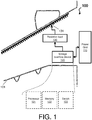
- FIG. 1 depicts a system 100 for preserving power quality in accordance with one or more embodiments.
- the system 100 can be implemented on an aircraft 101, such as an airplane or helicopter, but also a boat or other vehicle. For ease of explanation, the system is described with respect to the aircraft 101.
- the system 100 includes a power grid 110 and a voltage overflow device 120, which can further include a processor 121, a memory 122, and a switch 123.
- the system 100 also includes a resistive load 130, which by way of example can include an electrical deicing or anticing system 131 of an aircraft comprised of electrically resistive elements.
- the system 100 implements a way of preserving a power quality on "an island of power,” (e.g., on the power grid 110 of the aircraft 101) by utilizing the resistive load 130. That is, instead of shorting out a given point in the power grid 110 to arrest an overvoltage, the system 100 closes the switch 123 to route the overvoltage to the resistive load 130, thereby dumping the excess power on the grid 110 into the resistive load 130.
- the power grid 110 is an interconnected electric cabling network for delivering electricity from producers (e.g., a jet engine, auxiliary power unit, batteries, solar panels, fuel cells, ultracapacitors) to consumers (e.g., lights, actuators, fans, flight sensors, communication systems).
- producers e.g., a jet engine, auxiliary power unit, batteries, solar panels, fuel cells, ultracapacitors
- consumers e.g., lights, actuators, fans, flight sensors, communication systems.
- the power grid 110 runs throughout the aircraft 101.
- the voltage overflow device 120 is an electric mechanism or computer that when a predetermined voltage is exceeded, shunts all undesired power to the resistive load 130.
- the voltage overflow device 120 can comprise any number of circuits and/or components to shunt the excess power or over voltage.
- the voltage overflow device 120 is electrically coupled to the power grid through at least one electrical contact and is electrically coupled to the resistive load 130 (and the electrical deicing or anticing system 131).
- the voltage overflow device 120 can be any computing device with one or more central processing units (referred to as the processor 121).
- the processor 121 is coupled via a system bus to the memory 122, the switch 123, and various other components.
- the memory 122 can include a read only memory (ROM) and a random access memory (RAM).
- the memory 122 is an example of a tangible storage medium readable by the processor 121, where the software is stored on the memory 122 as instructions for execution to cause the voltage overflow device 120 to operate, such as is described herein with reference to FIGS. 2-3 .
- the switch 123 is an electrical component that can "make” or “break” an electrical circuit, by interrupting the current or diverting it from one point (at least one electrical contact on the power grid 110) to another point (the resistive load 130).
- the voltage overflow device 120 can be and/or include a field programable gate array, a microcontroller, or other integrated circuit (e.g., a voltage monitoring circuit) with a programmable threshold (e.g., a predetermined voltage) stored therein.
- the voltage overflow device 120 can include a Zener diode (sized accordingly) with a breakdown voltage (e.g., a predetermined voltage) equivalent to a maximum desired voltage on a point of the power grid 110 to which the Zener diode is connected (such that the voltage overflow device 120 described herein operates with reference to FIGS. 2-3 ).
- a breakdown voltage e.g., a predetermined voltage
- the Zener diode provides a current by turning on the switch 123 that connects, via electrical contacts, the point of the power grid 110 to the electrical deicing or anticing system 131 acting as a load bank to accept the excess energy.
- the resistive load 130 is any system, device or component that converts current with respect to excess voltage on the power grid 110 to other forms of energy.
- the resistive load 130 can include, in addition to or in lieu of the electrical deicing or anticing system 131, any substantial load on the aircraft 101 capable of handling the excess voltage.
- the electrical deicing or anticing system 131 includes electrical anti/deicing pads, blankets, heaters, etc.
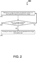
- FIG. 2 depicts a process flow 200 of the system 100 for preserving power quality in accordance with one or more embodiments.
- the process flow 200 is a method implemented by the voltage overflow device 120 to preserve the power quality on the power grid 100.
- the process flow 200 begins at block 210, where a voltage monitoring circuit of the voltage overflow device 120 monitors a voltage via the at least one electrical contact on the power grid 100 with respect to a predetermined voltage.
- the predetermined voltage can be 270 volts.
- the voltage monitoring circuit determines whether the voltage exceeds the predetermined voltage. If the voltage does not exceed the predetermined voltage, the process flow 200 returns to block 210 (as shown by the No arrow). If the voltage exceeds the predetermined voltage, the process flow 200 proceeds to block 230 (as shown by the yes arrow). Continuing with the above example, if the voltage on the power grid 110 goes to 300 volts, the voltage monitoring circuit would detect this overload with respect to the 270 predetermined voltage.
- the switch 123 shunts an excess voltage over the predetermined voltage to the resistive load 130 (i.e., when the voltage exceeds the predetermined voltage) to preserve the power quality on the power grid 100. For example, any excess power over 270 volts is directed to the electrical deicing or anticing system 131.
- FIG. 3 depicts a process flow 300 of the system 100 for preserving power quality in accordance with one or more embodiments.
- the process flow 300 is a method implemented by the voltage overflow device 120 to preserve the power quality on the power grid 100.
- the process flow 300 begins at block 310, where a voltage monitoring circuit of the voltage overflow device 120 monitors a voltage via electrical contacts on the power grid 100 with respect to a predetermined voltage.
- the predetermined voltage can be 270 volts.
- the voltage monitoring circuit determines whether the voltage exceeds the predetermined voltage. If the voltage does not exceed the predetermined voltage, the process flow 300 returns to block 310 (as shown by the No arrow). If the voltage exceeds the predetermined voltage, the process flow 300 proceeds to block 330 (as shown by the Yes arrow). Continuing with the above example, if the voltage on the power grid 110 goes to 300 volts, the voltage monitoring circuit would detect this overload with respect to the 270 predetermined voltage.
- the switch 123 shunts an excess voltage over the predetermined voltage to the resistive load 130 (i.e., when the voltage exceeds the predetermined voltage) to preserve the power quality on the power grid 100. For example, any excess power over 270 volts is directed to the electrical deicing or anticing system 131.
- the voltage monitoring circuit continues to monitor the voltage via the electrical contacts on the power grid 100 with respect to the predetermined voltage during the shunting.
- the voltage monitoring circuit determines whether the voltage is below the predetermined voltage. If the voltage is not below the predetermined voltage, the process flow 300 returns to block 330 (as shown by the No arrow). In turn, the voltage monitoring circuit maintains the shunt. If the voltage is below the predetermined voltage, the process flow 300 returns to block 310 (as shown by the Yes arrow). Continuing with the above example, if the voltage on the power grid 110 goes to 300 volts, the voltage monitoring circuit would detect this overload with respect to the 270 predetermined voltage.
Landscapes
- Engineering & Computer Science (AREA)
- Chemical & Material Sciences (AREA)
- Combustion & Propulsion (AREA)
- Aviation & Aerospace Engineering (AREA)
- Power Engineering (AREA)
- Mechanical Engineering (AREA)
- General Engineering & Computer Science (AREA)
- Protection Of Static Devices (AREA)
Abstract
Description
- There are several instances where "excess" power can exist within aircraft electrical power systems. In some cases, a presence of excess power can be intentional, as in the case where batteries are being charged. But, in other cases, the presence of excess power can actually damage equipment through overvoltage type events.
- Excess power is serious, and dedicated controls are used to make sure that overvoltage cannot occur or persist. These controls sometimes use "crowbars" to dead short an offending circuit, i.e., sacrificially dumping power into the crowbar. Further, regenerative power, from things like electric actuation systems, has further added to excess power concerns within aircraft electrical power systems, as regenerative power is very erratic and provides undesired voltage rises within these systems.
- In accordance with one or more embodiments, a method of preserving power quality on a power grid where a voltage overflow device is electrically coupled to the power grid through at least one electrical contact is provided. The method includes monitoring, by a voltage monitoring circuit of the voltage overflow device, a voltage via the at least one electrical contact on the power grid with respect to a predetermined voltage; determining, by the voltage monitoring circuit of the voltage overflow device, whether the voltage exceeds the predetermined voltage; and shunting, by a switch of the voltage overflow device, an excess voltage over the predetermined voltage to a resistive load when the voltage exceeds the predetermined voltage to preserve the power quality on the power grid.
- In accordance with one or more embodiments or the method embodiment above, the voltage monitoring circuit can continue to monitor the voltage on the at least one electrical contact on the power grid with respect to the predetermined voltage during the shunting.
- In accordance with one or more embodiments or any of the method embodiments above, the voltage monitoring circuit can determine that the voltage is below the predetermined voltage and removes the shunt.
- In accordance with one or more embodiments or the method embodiment above, the voltage monitoring circuit can determine that the voltage exceeds the predetermined voltage and maintains the shunt.
- In accordance with one or more embodiments or the method embodiment above, the voltage overflow device can include a memory storing the predetermined voltage.
- In accordance with one or more embodiments or the method embodiment above, the power grid can include an electrical system of an aircraft.
- In accordance with one or more embodiments or the method embodiment above, the resistive load can include an electrical deicing or anticing system of an aircraft comprised of electrically resistive elements.
- In accordance with one or more embodiments, a voltage overflow device for preserving power quality on a power grid is provided. The voltage overflow device being electrically coupled to the power grid through at least one electrical contact. The voltage overflow device includes a voltage monitoring circuit configured to monitor a voltage via the at least one electrical contact on the power grid with respect to a predetermined voltage and determine when the voltage exceeds the predetermined voltage. The voltage overflow device includes a switch configured to shunt an excess voltage over the predetermined voltage to a resistive load in accordance with the voltage monitoring circuit determining that the voltage exceeds the predetermined voltage to preserve the power quality on the power grid.
- In accordance with one or more embodiments or the voltage overflow device embodiment above, the voltage monitoring circuit can continue to monitor the voltage on the at least one electrical contact on the power grid with respect to the predetermined voltage during the shunting.
- In accordance with one or more embodiments or any of the voltage overflow device embodiments above, the voltage monitoring circuit can determine that the voltage is below the predetermined voltage and removes the shunt.
- In accordance with one or more embodiments or the voltage overflow device embodiment above, the voltage monitoring circuit can determine that the voltage exceeds the predetermined voltage and maintains the shunt.
- In accordance with one or more embodiments or the voltage overflow device embodiment above, the voltage overflow device can include a memory storing the predetermined voltage.
- In accordance with one or more embodiments or the voltage overflow device embodiment above, the power grid can include an electrical system of an aircraft.
- In accordance with one or more embodiments or the voltage overflow device embodiment above, the resistive load can include an electrical deicing or anticing system of an aircraft comprised of electrically resistive elements.
- In accordance with one or more embodiments, a system for preserving power quality on a power grid is provided. The system includes a power grid; a resistive load; and a voltage overflow device. The voltage overflow device being electrically coupled to the power grid through at least one electrical contact. The voltage overflow device including a voltage monitoring circuit configured to monitor a voltage via the at least one electrical contact on the power grid with respect to a predetermined voltage and determine when the voltage exceeds the predetermined voltage. The voltage overflow device including a switch configured to shunt an excess voltage over the predetermined voltage to the resistive load in accordance with the voltage monitoring circuit determining that the voltage exceeds the predetermined voltage to preserve the power quality on the power grid.
- In accordance with one or more embodiments or the system embodiment above, the voltage monitoring circuit can continue to monitor the voltage on the at least one electrical contact on the power grid with respect to the predetermined voltage during the shunting.
- In accordance with one or more embodiments or any of the system embodiments above, the voltage monitoring circuit can determine that the voltage is below the predetermined voltage and removes the shunt.
- In accordance with one or more embodiments or the voltage overflow device embodiment above, the voltage monitoring circuit can determine that the voltage exceeds the predetermined voltage and maintains the shunt.
- In accordance with one or more embodiments or the system embodiment above, the voltage overflow device can include a memory storing the predetermined voltage.
- In accordance with one or more embodiments or the system embodiment above, the power grid can include an electrical system of an aircraft.
- In accordance with one or more embodiments or the system embodiment above, the resistive load can include an electrical deicing or anticing system of an aircraft comprised of electrically resistive elements.
- The following descriptions should not be considered limiting in any way. With reference to the accompanying drawings, like elements are numbered alike:
-
FIG. 1 depicts a system for preserving power quality in accordance with one or more embodiments; -
FIG. 2 depicts a process flow of a system for preserving power quality in accordance with one or more embodiments; and -
FIG. 3 depicts a process flow of a system for preserving power quality in accordance with one or more embodiments. - A detailed description of one or more embodiments of the disclosed apparatus and method are presented herein by way of exemplification and not limitation with reference to the Figures.
-
FIG. 1 depicts asystem 100 for preserving power quality in accordance with one or more embodiments. Thesystem 100 can be implemented on anaircraft 101, such as an airplane or helicopter, but also a boat or other vehicle. For ease of explanation, the system is described with respect to theaircraft 101. Thesystem 100 includes apower grid 110 and avoltage overflow device 120, which can further include aprocessor 121, amemory 122, and aswitch 123. Thesystem 100 also includes aresistive load 130, which by way of example can include an electrical deicing oranticing system 131 of an aircraft comprised of electrically resistive elements. - In general, the
system 100 implements a way of preserving a power quality on "an island of power," (e.g., on thepower grid 110 of the aircraft 101) by utilizing theresistive load 130. That is, instead of shorting out a given point in thepower grid 110 to arrest an overvoltage, thesystem 100 closes theswitch 123 to route the overvoltage to theresistive load 130, thereby dumping the excess power on thegrid 110 into theresistive load 130. - Technical effects and benefits of embodiments herein include usage of onboard equipment (e.g., the electrical deicing or anticing system) to allow removal of dedicated overvoltage protection units, while providing an efficient use of excess power. These technical effects and benefits are necessarily rooted in the
voltage overflow device 120, and the processor therein 121, to overcome problems arising in conventional aircraft electrical power systems. In this regard, leveraging the electrical deicing oranticing system 131 to solve a problem associated with the conventional aircraft electrical power systems also saves weight of redundant solutions, such as crowbar overvoltage protection units, and provides useful work for energy captured on the power grid 110 (e.g. regenerative power from actuators). - The
power grid 110 is an interconnected electric cabling network for delivering electricity from producers (e.g., a jet engine, auxiliary power unit, batteries, solar panels, fuel cells, ultracapacitors) to consumers (e.g., lights, actuators, fans, flight sensors, communication systems). In the above example, thepower grid 110 runs throughout theaircraft 101. - The
voltage overflow device 120 is an electric mechanism or computer that when a predetermined voltage is exceeded, shunts all undesired power to theresistive load 130. Thevoltage overflow device 120 can comprise any number of circuits and/or components to shunt the excess power or over voltage. Thevoltage overflow device 120 is electrically coupled to the power grid through at least one electrical contact and is electrically coupled to the resistive load 130 (and the electrical deicing or anticing system 131). - In accordance with one or more embodiments, the
voltage overflow device 120 can be any computing device with one or more central processing units (referred to as the processor 121). Theprocessor 121 is coupled via a system bus to thememory 122, theswitch 123, and various other components. Thememory 122 can include a read only memory (ROM) and a random access memory (RAM). Thememory 122 is an example of a tangible storage medium readable by theprocessor 121, where the software is stored on thememory 122 as instructions for execution to cause thevoltage overflow device 120 to operate, such as is described herein with reference toFIGS. 2-3 . Theswitch 123 is an electrical component that can "make" or "break" an electrical circuit, by interrupting the current or diverting it from one point (at least one electrical contact on the power grid 110) to another point (the resistive load 130). For example, thevoltage overflow device 120 can be and/or include a field programable gate array, a microcontroller, or other integrated circuit (e.g., a voltage monitoring circuit) with a programmable threshold (e.g., a predetermined voltage) stored therein. - In accordance with one or more embodiments, when the
power grid 110 is a DC system, thevoltage overflow device 120 can include a Zener diode (sized accordingly) with a breakdown voltage (e.g., a predetermined voltage) equivalent to a maximum desired voltage on a point of thepower grid 110 to which the Zener diode is connected (such that thevoltage overflow device 120 described herein operates with reference toFIGS. 2-3 ). When conducting, the Zener diode provides a current by turning on theswitch 123 that connects, via electrical contacts, the point of thepower grid 110 to the electrical deicing oranticing system 131 acting as a load bank to accept the excess energy. - The
resistive load 130 is any system, device or component that converts current with respect to excess voltage on thepower grid 110 to other forms of energy. Theresistive load 130 can include, in addition to or in lieu of the electrical deicing oranticing system 131, any substantial load on theaircraft 101 capable of handling the excess voltage. The electrical deicing oranticing system 131 includes electrical anti/deicing pads, blankets, heaters, etc. -
FIG. 2 depicts aprocess flow 200 of thesystem 100 for preserving power quality in accordance with one or more embodiments. For example, theprocess flow 200 is a method implemented by thevoltage overflow device 120 to preserve the power quality on thepower grid 100. - The
process flow 200 begins atblock 210, where a voltage monitoring circuit of thevoltage overflow device 120 monitors a voltage via the at least one electrical contact on thepower grid 100 with respect to a predetermined voltage. For instance, the predetermined voltage can be 270 volts. - At
decision block 220, the voltage monitoring circuit determines whether the voltage exceeds the predetermined voltage. If the voltage does not exceed the predetermined voltage, theprocess flow 200 returns to block 210 (as shown by the No arrow). If the voltage exceeds the predetermined voltage, theprocess flow 200 proceeds to block 230 (as shown by the yes arrow). Continuing with the above example, if the voltage on thepower grid 110 goes to 300 volts, the voltage monitoring circuit would detect this overload with respect to the 270 predetermined voltage. - At
block 230, theswitch 123 shunts an excess voltage over the predetermined voltage to the resistive load 130 (i.e., when the voltage exceeds the predetermined voltage) to preserve the power quality on thepower grid 100. For example, any excess power over 270 volts is directed to the electrical deicing oranticing system 131. -
FIG. 3 depicts aprocess flow 300 of thesystem 100 for preserving power quality in accordance with one or more embodiments. For example, theprocess flow 300 is a method implemented by thevoltage overflow device 120 to preserve the power quality on thepower grid 100. Theprocess flow 300 begins atblock 310, where a voltage monitoring circuit of thevoltage overflow device 120 monitors a voltage via electrical contacts on thepower grid 100 with respect to a predetermined voltage. For instance, the predetermined voltage can be 270 volts. - At
decision block 320, the voltage monitoring circuit determines whether the voltage exceeds the predetermined voltage. If the voltage does not exceed the predetermined voltage, theprocess flow 300 returns to block 310 (as shown by the No arrow). If the voltage exceeds the predetermined voltage, theprocess flow 300 proceeds to block 330 (as shown by the Yes arrow). Continuing with the above example, if the voltage on thepower grid 110 goes to 300 volts, the voltage monitoring circuit would detect this overload with respect to the 270 predetermined voltage. - At
block 330, theswitch 123 shunts an excess voltage over the predetermined voltage to the resistive load 130 (i.e., when the voltage exceeds the predetermined voltage) to preserve the power quality on thepower grid 100. For example, any excess power over 270 volts is directed to the electrical deicing oranticing system 131. - At
block 340, the voltage monitoring circuit continues to monitor the voltage via the electrical contacts on thepower grid 100 with respect to the predetermined voltage during the shunting. - At
decision block 350, the voltage monitoring circuit determines whether the voltage is below the predetermined voltage. If the voltage is not below the predetermined voltage, theprocess flow 300 returns to block 330 (as shown by the No arrow). In turn, the voltage monitoring circuit maintains the shunt. If the voltage is below the predetermined voltage, theprocess flow 300 returns to block 310 (as shown by the Yes arrow). Continuing with the above example, if the voltage on thepower grid 110 goes to 300 volts, the voltage monitoring circuit would detect this overload with respect to the 270 predetermined voltage. - The term "about" is intended to include the degree of error associated with measurement of the particular quantity based upon the equipment available at the time of filing the application.
- The terminology used herein is for the purpose of describing particular embodiments only and is not intended to be limiting of the present disclosure. As used herein, the singular forms "a", "an" and "the" are intended to include the plural forms as well, unless the context clearly indicates otherwise. It will be further understood that the terms "comprises" and/or "comprising," when used in this specification, specify the presence of stated features, integers, steps, operations, elements, and/or components, but do not preclude the presence or addition of one or more other features, integers, steps, operations, element components, and/or groups thereof.
- While the present disclosure has been described with reference to an exemplary embodiment or embodiments, it will be understood by those skilled in the art that various changes may be made and equivalents may be substituted for elements thereof without departing from the scope of the invention as defined by the claims. In addition, many modifications may be made to adapt a particular situation or material to the teachings of the present disclosure without departing from the scope of the invention. Therefore, it is intended that the present disclosure not be limited to the particular embodiment disclosed as the best mode contemplated for carrying out this present disclosure, but that the present disclosure will include all embodiments falling within the scope of the claims.
Claims (15)
- A method of preserving power quality on a power grid (110) where a voltage overflow device (120) is electrically coupled to the power grid through at least one electrical contact, the method comprising:monitoring, by a voltage monitoring circuit of the voltage overflow device, a voltage via the at least one electrical contact on the power grid with respect to a predetermined voltage;determining, by the voltage monitoring circuit of the voltage overflow device, whether the voltage exceeds the predetermined voltage; andshunting, by a switch (123) of the voltage overflow device, an excess voltage over the predetermined voltage to a resistive load (130) when the voltage exceeds the predetermined voltage to preserve the power quality on the power grid.
- The method of claim 1, wherein the voltage monitoring circuit continues to monitor the voltage on the at least one electrical contact on the power grid with respect to the predetermined voltage during the shunting.
- The method of claim 2, wherein the voltage monitoring circuit determines that the voltage is below the predetermined voltage and removes the shunt.
- The method of claim 2, wherein the voltage monitoring circuit determines that the voltage exceeds the predetermined voltage and maintains the shunt.
- The method of any preceding claim, wherein the voltage overflow device comprises a memory (122) storing the predetermined voltage.
- The method of any preceding claim, wherein the power grid comprises an electrical system of an aircraft.
- The method of any preceding claim, wherein the resistive load (130) comprises an electrical deicing or anticing system (131) of an aircraft comprised of electrically resistive elements.
- A voltage overflow device for preserving power quality on a power grid (110), the voltage overflow device being electrically coupled to the power grid through at least one electrical contact, the voltage overflow device comprising:a voltage monitoring circuit configured to monitor a voltage via the at least one electrical contact on the power grid with respect to a predetermined voltage and determine when the voltage exceeds the predetermined voltage; anda switch (123) configured to shunt an excess voltage over the predetermined voltage to a resistive load (130) in accordance with the voltage monitoring circuit determining that the voltage exceeds the predetermined voltage to preserve the power quality on the power grid.
- The voltage overflow device of claim 8, wherein the voltage monitoring circuit continues to monitor the voltage on the at least one contact on the power grid with respect to the predetermined voltage during the shunting.
- The voltage overflow device of claim 9, wherein the voltage monitoring circuit determines that the voltage is below the predetermined voltage and removes the shunt.
- The voltage overflow device of claim 9, wherein the voltage monitoring circuit determines that the voltage exceeds the predetermined voltage and maintains the shunt.
- The voltage overflow device of any of claims 8 to 11, wherein the voltage overflow device comprises a memory storing the predetermined voltage.
- The voltage overflow device of any of claims 8 to 12, wherein the power grid comprises an electrical system of an aircraft.
- The voltage overflow device of any of claims 8 to 13, wherein the resistive load (130) comprises an electrical deicing or anticing system (131) of an aircraft comprised of electrically resistive elements.
- A system for preserving power quality on a power grid, the system comprising:a power grid (110);a resistive load (130); anda voltage overflow device (120) as claimed in any of claims 8 to 14 being electrically coupled to the power grid through the at least one electrical contact.
Applications Claiming Priority (1)
| Application Number | Priority Date | Filing Date | Title |
|---|---|---|---|
| US16/105,700 US10975768B2 (en) | 2018-08-20 | 2018-08-20 | Using aircraft electric icing protection system for electrical power system quality |
Publications (1)
| Publication Number | Publication Date |
|---|---|
| EP3614516A1 true EP3614516A1 (en) | 2020-02-26 |
Family
ID=67658801
Family Applications (1)
| Application Number | Title | Priority Date | Filing Date |
|---|---|---|---|
| EP19191704.6A Withdrawn EP3614516A1 (en) | 2018-08-20 | 2019-08-14 | Using aircraft electric icing protection system for electrical power system quality |
Country Status (2)
| Country | Link |
|---|---|
| US (1) | US10975768B2 (en) |
| EP (1) | EP3614516A1 (en) |
Families Citing this family (1)
| Publication number | Priority date | Publication date | Assignee | Title |
|---|---|---|---|---|
| EP3854691A1 (en) * | 2020-01-24 | 2021-07-28 | Goodrich Corporation | Ice detection arrangement |
Citations (6)
| Publication number | Priority date | Publication date | Assignee | Title |
|---|---|---|---|---|
| WO2004057174A1 (en) * | 2002-12-20 | 2004-07-08 | Turbec Ab | Transient equalization method and apparatus |
| US20140070054A1 (en) * | 2010-12-31 | 2014-03-13 | Battelle Memorial Institute | Anti-icing, de-icing, and heating configuration, integration, and power methods for aircraft, aerodynamic, and complex surfaces |
| WO2014074101A1 (en) * | 2012-11-09 | 2014-05-15 | United Technologies Corporation | Responding to positive rate of change of fuel cell voltage during power reduction transitions |
| US20160359314A1 (en) * | 2015-06-02 | 2016-12-08 | Seagate Technology Llc | Adaptive power dumper |
| EP3288137A1 (en) * | 2016-08-22 | 2018-02-28 | GE Aviation Systems LLC | Surge protection circuit |
| US20180138716A1 (en) * | 2015-05-06 | 2018-05-17 | Ge Aviation Systems Limited | System and method for power distribution |
Family Cites Families (16)
| Publication number | Priority date | Publication date | Assignee | Title |
|---|---|---|---|---|
| US4355239A (en) | 1980-01-15 | 1982-10-19 | Lucas Industries Limited | Electrical power supply arrangement |
| US4678144A (en) | 1984-10-26 | 1987-07-07 | Simmonds Precision | Electro-impulse de-icing system for aircraft |
| CN85103680A (en) | 1985-05-20 | 1987-01-21 | 联合工艺公司 | The fender guard that the prevention temperature booster that uses in the aircraft propeller deicing system burns out |
| US4814931A (en) * | 1987-01-15 | 1989-03-21 | The B. F. Goodrich Company | Apparatus and method for timed-de-icing |
| US4895322A (en) * | 1987-09-18 | 1990-01-23 | Zieve Peter B | Self-contained apparatus for de-icing aircraft surfaces using magnetic pulse energy |
| US5114103A (en) | 1990-08-27 | 1992-05-19 | General Electric Company | Aircraft engine electrically powered boundary layer bleed system |
| US6237874B1 (en) * | 1997-09-22 | 2001-05-29 | Northcoast Technologies | Zoned aircraft de-icing system and method |
| FR2891241B1 (en) * | 2005-09-23 | 2009-03-13 | Airbus France Sas | SYSTEM FOR DEFROSTING AND / OR DEMANDING AN AIRCRAFT SURFACE, METHOD FOR CONTROLLING SUCH A SYSTEM, AND AIRCRAFT EQUIPPED WITH SUCH A SYSTEM. |
| US7550866B2 (en) * | 2006-12-20 | 2009-06-23 | The Boeing Company | Vehicular power distribution system and method |
| US8746622B2 (en) * | 2010-06-08 | 2014-06-10 | Textron Innovations Inc. | Aircraft de-icing system and method |
| FR2961177B1 (en) * | 2010-06-11 | 2013-02-15 | Hispano Suiza Sa | POWER SUPPLY CIRCUIT FOR AN AIRCRAFT DE-ICING CIRCUIT |
| US8738268B2 (en) | 2011-03-10 | 2014-05-27 | The Boeing Company | Vehicle electrical power management and distribution |
| FR3000724B1 (en) * | 2013-01-07 | 2015-01-02 | Aircelle Sa | ELECTRIC DEGIVING ARCHITECTURE WITH HIGH AVAILABILITY OF AIR INTAKE OF SWING RACK |
| US9523594B1 (en) * | 2016-02-23 | 2016-12-20 | Honeywell International Inc. | Power control for an air data probe |
| US20170259927A1 (en) * | 2016-03-14 | 2017-09-14 | Rosemount Aerospace, Inc. | Ac power heater short-to-chassis ground detection circuit |
| US10464680B2 (en) * | 2016-08-30 | 2019-11-05 | The Boeing Company | Electrically conductive materials for heating and deicing airfoils |
-
2018
- 2018-08-20 US US16/105,700 patent/US10975768B2/en active Active
-
2019
- 2019-08-14 EP EP19191704.6A patent/EP3614516A1/en not_active Withdrawn
Patent Citations (6)
| Publication number | Priority date | Publication date | Assignee | Title |
|---|---|---|---|---|
| WO2004057174A1 (en) * | 2002-12-20 | 2004-07-08 | Turbec Ab | Transient equalization method and apparatus |
| US20140070054A1 (en) * | 2010-12-31 | 2014-03-13 | Battelle Memorial Institute | Anti-icing, de-icing, and heating configuration, integration, and power methods for aircraft, aerodynamic, and complex surfaces |
| WO2014074101A1 (en) * | 2012-11-09 | 2014-05-15 | United Technologies Corporation | Responding to positive rate of change of fuel cell voltage during power reduction transitions |
| US20180138716A1 (en) * | 2015-05-06 | 2018-05-17 | Ge Aviation Systems Limited | System and method for power distribution |
| US20160359314A1 (en) * | 2015-06-02 | 2016-12-08 | Seagate Technology Llc | Adaptive power dumper |
| EP3288137A1 (en) * | 2016-08-22 | 2018-02-28 | GE Aviation Systems LLC | Surge protection circuit |
Also Published As
| Publication number | Publication date |
|---|---|
| US10975768B2 (en) | 2021-04-13 |
| US20200055607A1 (en) | 2020-02-20 |
Similar Documents
| Publication | Publication Date | Title |
|---|---|---|
| EP3203251B1 (en) | Shared transient voltage suppressor for protecting multiple load channels of a solid state power controller having built-in-test capability | |
| EP4044394A1 (en) | Systems and methods for fail-safe battery protection independent from battery management system | |
| EP3041101B1 (en) | System for improving lightning immunity for a solid state power controller | |
| EP1921531A1 (en) | Solid state power controller with lightning protection | |
| US10972087B2 (en) | System and method for limting currents in a power distribution system | |
| EP3652833B1 (en) | Charging system | |
| US8564914B2 (en) | Fault clearing without a DC backup power source | |
| US9362544B2 (en) | Systems and methods for control of a current interruption component in a battery system | |
| CN103378590B (en) | Sub-transient current suppression | |
| DE102016216341A1 (en) | A power interruption assembly, battery system, controller, and method for separating a flow of current between a battery and a consumer of the battery | |
| CN205265251U (en) | A device for overvoltage protection in power supply line | |
| CN102646960A (en) | Battery pack primary loop interface protection circuit and protection method | |
| CN104025369A (en) | Battery system and motor vehicle | |
| US10975768B2 (en) | Using aircraft electric icing protection system for electrical power system quality | |
| CN102842881A (en) | Grounding protection device and thin film battery generating device based on grounding protection device | |
| CN105958437B (en) | Realize the control circuit of breaker decompression tripping in external circuit | |
| DE102017115636B4 (en) | Power electronic system | |
| US10500960B2 (en) | Method for operating an electrical system of a motor vehicle, and motor vehicle | |
| CN116526660A (en) | Circuit of intelligent solid-state switch and control strategy optimization method | |
| RU165059U1 (en) | ELECTRIC CAR | |
| US12266921B2 (en) | Installation including a stored energy source and an electric motor which can be fed by an inverter, and method for operating an installation | |
| US20260012000A1 (en) | Electrical device for protecting an electrical power supply installation | |
| CN114523848B (en) | Vehicle-mounted power system with two vehicle-mounted power subsystems and protection device therebetween | |
| US20210399569A1 (en) | Method for operating an electrical energy store | |
| DE102020116974A1 (en) | Circuit breaker for direct currents |
Legal Events
| Date | Code | Title | Description |
|---|---|---|---|
| PUAI | Public reference made under article 153(3) epc to a published international application that has entered the european phase |
Free format text: ORIGINAL CODE: 0009012 |
|
| STAA | Information on the status of an ep patent application or granted ep patent |
Free format text: STATUS: THE APPLICATION HAS BEEN PUBLISHED |
|
| AK | Designated contracting states |
Kind code of ref document: A1 Designated state(s): AL AT BE BG CH CY CZ DE DK EE ES FI FR GB GR HR HU IE IS IT LI LT LU LV MC MK MT NL NO PL PT RO RS SE SI SK SM TR |
|
| AX | Request for extension of the european patent |
Extension state: BA ME |
|
| STAA | Information on the status of an ep patent application or granted ep patent |
Free format text: STATUS: REQUEST FOR EXAMINATION WAS MADE |
|
| 17P | Request for examination filed |
Effective date: 20200825 |
|
| RBV | Designated contracting states (corrected) |
Designated state(s): AL AT BE BG CH CY CZ DE DK EE ES FI FR GB GR HR HU IE IS IT LI LT LU LV MC MK MT NL NO PL PT RO RS SE SI SK SM TR |
|
| STAA | Information on the status of an ep patent application or granted ep patent |
Free format text: STATUS: EXAMINATION IS IN PROGRESS |
|
| 17Q | First examination report despatched |
Effective date: 20211001 |
|
| STAA | Information on the status of an ep patent application or granted ep patent |
Free format text: STATUS: THE APPLICATION IS DEEMED TO BE WITHDRAWN |
|
| 18D | Application deemed to be withdrawn |
Effective date: 20220412 |