EP3614494A1 - Performante magnetisch induktive antenne für ein hörgerät - Google Patents
Performante magnetisch induktive antenne für ein hörgerät Download PDFInfo
- Publication number
- EP3614494A1 EP3614494A1 EP19185643.4A EP19185643A EP3614494A1 EP 3614494 A1 EP3614494 A1 EP 3614494A1 EP 19185643 A EP19185643 A EP 19185643A EP 3614494 A1 EP3614494 A1 EP 3614494A1
- Authority
- EP
- European Patent Office
- Prior art keywords
- antenna
- base
- ferrite core
- film
- carrier
- Prior art date
- Legal status (The legal status is an assumption and is not a legal conclusion. Google has not performed a legal analysis and makes no representation as to the accuracy of the status listed.)
- Granted
Links
Images



Classifications
-
- H—ELECTRICITY
- H04—ELECTRIC COMMUNICATION TECHNIQUE
- H04R—LOUDSPEAKERS, MICROPHONES, GRAMOPHONE PICK-UPS OR LIKE ACOUSTIC ELECTROMECHANICAL TRANSDUCERS; ELECTRIC HEARING AIDS; PUBLIC ADDRESS SYSTEMS
- H04R25/00—Electric hearing aids
- H04R25/55—Electric hearing aids using an external connection, either wireless or wired
- H04R25/554—Electric hearing aids using an external connection, either wireless or wired using a wireless connection, e.g. between microphone and amplifier or using Tcoils
-
- H—ELECTRICITY
- H01—ELECTRIC ELEMENTS
- H01Q—ANTENNAS, i.e. RADIO AERIALS
- H01Q7/00—Loop antennas with a substantially uniform current distribution around the loop and having a directional radiation pattern in a plane perpendicular to the plane of the loop
- H01Q7/06—Loop antennas with a substantially uniform current distribution around the loop and having a directional radiation pattern in a plane perpendicular to the plane of the loop with core of ferromagnetic material
- H01Q7/08—Ferrite rod or like elongated core
-
- H—ELECTRICITY
- H01—ELECTRIC ELEMENTS
- H01Q—ANTENNAS, i.e. RADIO AERIALS
- H01Q1/00—Details of, or arrangements associated with, antennas
- H01Q1/27—Adaptation for use in or on movable bodies
- H01Q1/273—Adaptation for carrying or wearing by persons or animals
-
- H—ELECTRICITY
- H01—ELECTRIC ELEMENTS
- H01Q—ANTENNAS, i.e. RADIO AERIALS
- H01Q1/00—Details of, or arrangements associated with, antennas
- H01Q1/36—Structural form of radiating elements, e.g. cone, spiral, umbrella; Particular materials used therewith
- H01Q1/38—Structural form of radiating elements, e.g. cone, spiral, umbrella; Particular materials used therewith formed by a conductive layer on an insulating support
-
- H—ELECTRICITY
- H01—ELECTRIC ELEMENTS
- H01Q—ANTENNAS, i.e. RADIO AERIALS
- H01Q7/00—Loop antennas with a substantially uniform current distribution around the loop and having a directional radiation pattern in a plane perpendicular to the plane of the loop
- H01Q7/06—Loop antennas with a substantially uniform current distribution around the loop and having a directional radiation pattern in a plane perpendicular to the plane of the loop with core of ferromagnetic material
-
- H—ELECTRICITY
- H04—ELECTRIC COMMUNICATION TECHNIQUE
- H04R—LOUDSPEAKERS, MICROPHONES, GRAMOPHONE PICK-UPS OR LIKE ACOUSTIC ELECTROMECHANICAL TRANSDUCERS; ELECTRIC HEARING AIDS; PUBLIC ADDRESS SYSTEMS
- H04R2225/00—Details of deaf aids covered by H04R25/00, not provided for in any of its subgroups
- H04R2225/51—Aspects of antennas or their circuitry in or for hearing aids
-
- H—ELECTRICITY
- H04—ELECTRIC COMMUNICATION TECHNIQUE
- H04R—LOUDSPEAKERS, MICROPHONES, GRAMOPHONE PICK-UPS OR LIKE ACOUSTIC ELECTROMECHANICAL TRANSDUCERS; ELECTRIC HEARING AIDS; PUBLIC ADDRESS SYSTEMS
- H04R25/00—Electric hearing aids
- H04R25/55—Electric hearing aids using an external connection, either wireless or wired
-
- H—ELECTRICITY
- H04—ELECTRIC COMMUNICATION TECHNIQUE
- H04R—LOUDSPEAKERS, MICROPHONES, GRAMOPHONE PICK-UPS OR LIKE ACOUSTIC ELECTROMECHANICAL TRANSDUCERS; ELECTRIC HEARING AIDS; PUBLIC ADDRESS SYSTEMS
- H04R25/00—Electric hearing aids
- H04R25/70—Adaptation of deaf aid to hearing loss, e.g. initial electronic fitting
Definitions
- the invention relates to a magnetically inductive antenna for a hearing instrument and to a hearing instrument, in particular a hearing device, with such an antenna.
- Electronic instruments are generally referred to as hearing instruments, which emit a sound signal into the ear of a person wearing the hearing instrument (also referred to as “user” or “wearer”) and thus support the hearing of this person.
- this includes in particular hearing aids that serve to care for hearing-impaired wearers.
- Such hearing aids pick up ambient sound and transmit it to the user in processed, in particular frequency-dependent, amplified form as airborne and / or structure-borne sound, whereby they compensate for the hearing loss of the user entirely or at least partially.
- Similar to classic hearing aids other hearing instruments process ambient sound, but serve to supply users with normal hearing in order to protect their hearing ability in special situations (e.g. special sound-absorbing hearing instruments for musicians) or to support them in some other way.
- hearing instruments are also understood to mean devices that convert a wired or wirelessly received audio signal into airborne or structure-borne noise and emit it to the user in this form, e.g. Headphones, earpieces, etc.
- hearing instruments Different types are known. So-called “behind-the-ear devices” are worn between the skull and the auricle, with the amplified sound signal being inserted into the ear canal by means of a sound tube the person is introduced or is output by means of a sound transducer located in the ear canal (also referred to as a "receiver” or “receiver”).
- a sound transducer located in the ear canal
- hearing instrument is an "in-the-ear device” in which the entire hearing aid device itself is inserted into the ear, in particular into the auditory canal.
- cochlear implants There are also hearing instruments that transmit sound information in the form of structure-borne noise, such as so-called cochlear implants.
- Magnetic inductive near field transmission is used in hearing instruments as an alternative to traditional radio transmission technologies (e.g. Bluetooth) for the wireless transmission of data, especially audio signals, with external devices.
- traditional radio transmission technologies e.g. Bluetooth
- magnetic inductive near-field transmission is frequently used for the communication of two hearing instruments in a binaural hearing system.
- magnetic-inductive methods are also used for energy transmission, that is, for wireless charging of rechargeable batteries in hearing instruments.
- the MI antennas required for this i.e. for magnetic-inductive data and / or energy transmission
- the antenna performance can be increased here with larger ferrite cores, special wrapping and special ferrite materials. Due to the cramped installation space, the sensitive (and therefore prone to failure) electronics in hearing instruments and the desire for the lowest possible weight, the performance increase of conventional MI antennas for use in hearing instruments is limited.
- MI antennas i.e. antennas for magnetic inductive near-field transmission
- base the cross-section of the actual winding core
- screens These antenna surfaces (referred to as “screens” there) are oriented approximately orthogonally to the axis of the winding core.
- the antenna surfaces on the mutually facing inner sides are optionally available with a para- or diamagnetic one Provide layer through which the interior space formed between the antenna surfaces is magnetically shielded. Electrical or electronic components of the hearing device (for example the battery) can therefore be accommodated in a space-saving manner in the interior between the antenna surfaces.
- the invention is based on the object of further improving such a film antenna, in particular from a manufacturing point of view.
- the MI antenna according to the invention comprises two antenna surfaces which are formed from magnetic, flexible film.
- the MI antenna further comprises a base wound with an antenna winding.
- the two antenna surfaces are formed from separate magnetic film cuts.
- the base has an opening on each of the end faces (i.e. the surfaces opposite each other in the direction of the winding axis), into each of which one of the foil blanks (particularly with a tab) is inserted.
- the MI antenna according to the invention has the advantage that the base can be prefabricated detached from the antenna surfaces, the antenna winding in particular being able to be (and preferably also being) soldered favorably in terms of production technology using the reflow method.
- the film cuts are only inserted into the openings in the prefabricated base. This manufacturing concept enables an uncomplicated, automated production with conventional production machines.
- a flat overlap of the foil blanks with one another or with a ferrite core of the base can be achieved by the inserted foil blanks, whereby an efficient magnetic flux between the base and the antenna surfaces and thus a high antenna efficiency can be achieved.
- the first step and the second step are independent of each other. These steps can therefore be carried out in any chronological order (in particular also simultaneously or overlapping in time).
- the third step builds on the result of the previous steps and must therefore be carried out after these.
- the film cuts can have any external contour within the scope of the invention.
- the antenna areas e.g. each have a circular, semicircular or polygonal outer contour.
- the tabs to be inserted into the corresponding depressions of the base are preferably narrower than the associated antenna area (that is, they have a smaller width in comparison to the antenna area) and protrude from the edge of the antenna area.
- the film cuts not shown here are designed as in the Fig. 4 and 10 shown (circular antenna surfaces, each with a tab protruding from the edge thereof), and are inserted with the tabs into the front openings of the base.
- the film cuts not shown here are designed as in the Fig. 4 and 10 shown (circular antenna surfaces, each with a tab protruding from the edge thereof), and are inserted with the tabs into the front openings of the base.
- the diamagnetic copper layers When assembled, the diamagnetic copper layers rest on the antenna surfaces, as in Fig. 4-6 and 11 shown.
- Embodiment 5 (analog 10 and 11 ): Like embodiment 4, but with a plastic carrier instead of a hollow ferrite core
- Embodiment 6 (without drawing): as embodiment 4, but the tabs abut against one another inside the hollow ferrite core.
- Exemplary embodiment 7 (without drawing): as exemplary embodiment 4, 5 or 6, but the tabs are clamped inside the hollow ferrite core or plastic carrier by wedges pushed in at the end.
- the MI antenna is preferably used in a hearing instrument that picks up ambient noise and emits it in a processed, in particular amplified form into the ear of a person wearing the hearing instrument.
- the MI antenna is intended in particular for use in a hearing device, that is to say a hearing instrument which serves to care for hearing-impaired people.
- the MI antenna is used primarily for wireless data transmission with a peripheral device, e.g. B. another hearing instrument for the other ear, a remote control, etc. used.
- the MI antenna according to the invention is used as a charging coil for inductive and wireless energy transmission from a charging device (not shown further) to the hearing instrument.
Landscapes
- Engineering & Computer Science (AREA)
- Computer Networks & Wireless Communication (AREA)
- Health & Medical Sciences (AREA)
- General Health & Medical Sciences (AREA)
- Neurosurgery (AREA)
- Otolaryngology (AREA)
- Physics & Mathematics (AREA)
- Acoustics & Sound (AREA)
- Signal Processing (AREA)
- Support Of Aerials (AREA)
- Details Of Aerials (AREA)
Abstract
Description
- Die Erfindung bezieht auf eine magnetisch induktive Antenne für ein Hörinstrument sowie auf ein Hörinstrument, insbesondere Hörgerät, mit einer solchen Antenne.
- Als Hörinstrument werden allgemein elektronische Gerät bezeichnet, die ein Schallsignal in das Ohr einer das Hörinstrument tragenden Person (auch als "Nutzer" oder "Träger" bezeichnet) abgeben und somit das Hören dieser Person unterstützen. Hierunter fallen im engeren Sinne insbesondere Hörgeräte, die zur Versorgung hörgeschädigter Träger dienen. Solche Hörgeräte nehmen einen Umgebungsschall auf und geben diesen in bearbeiteter, insbesondere frequenzabhängig verstärkter Form als Luft- und/oder Körperschall an den Nutzer ab, wobei sie den Hörverlust des Nutzers ganz oder zumindest teilweise kompensieren. Weitere Hörinstrumente verarbeiten - ähnlich wie klassische Hörgeräte - einen aufgenommenen Umgebungsschall, dienen aber zur Versorgung von normalhörenden Nutzern, um deren Hörvermögen in besonderen Situationen zu schonen (z.B. spezielle schalldämpfende Hörinstrumente für Musiker) oder in sonstiger Weise zu unterstützen. Als Hörinstrumente werden hier um im Folgenden aber auch Geräte verstanden, die ein drahtgebunden oder drahtlos empfangenes Audiosignal in Luft- oder Körperschall umwandeln und in dieser Form an den Nutzer abgeben, z.B. Kopfhörer, Ohrstücke, etc.
- Es sind unterschiedliche Bauformen von Hörinstrumenten bekannt. So werden sogenannte "Hinter-dem-Ohr-Geräte" zwischen Schädel und Ohrmuschel getragen, wobei das verstärkte Schallsignal mittels eines Schallschlauchs in den Gehörgang der Person eingeleitet wird oder mittels eines in dem Ohrkanal sitzenden Schallwandlers (auch als "Hörer" oder "Receiver" bezeichnet) ausgeben wird. Eine weitere Ausführung eines Hörinstruments ist ein "Im-Ohr-Gerät", bei dem das gesamte Hörhilfegerät selbst in das Ohr, insbesondere in den Gehörgang eingebracht wird. Des Weiteren gibt es Hörinstrumente, die die Schallinformation in Form von Körperschall übertragen, z.B. sogenannte Cochlea-Implantate.
- Magnetisch induktive Nahfeld-Übertragung wird bei Hörinstrumenten alternativ zu klassischen Funkübertragungstechniken (z.B. Bluetooth) für die drahtlose Übertragung von Daten, insbesondere Audiosignalen, mit externen Geräten verwendet. Insbesondere wird magnetisch induktive Nahfeld-Übertragung häufig für die Kommunikation zweier Hörinstrumente eines binauralen Hörsystems eingesetzt.
- Des Weiteren werden magnetisch-induktive Verfahren auch zur Energieübertragung, also zum drahtlosen Laden wiederaufladbarer Batterien in Hörinstrumenten verwendet.
- Bisher wurden die hierfür (also zur magnetisch-induktiven Daten- und/oder Energieübertragung) erforderlichen MI-Antennen regelmäßig durch einen bloßen bewickelten Ferritkern hergestellt. Die Antennenleistung lässt sich hier durch größere Ferritkerne, spezielle Bewicklung und besondere Ferritmaterialien steigern. Aufgrund des beengten Bauraums, der empfindlichen (und damit störanfälligen) Elektronik in Hörinstrumenten und dem Wunsch nach möglichst geringem Gewicht sind der Leistungssteigerung herkömmlicher MI-Antennen für den Einsatz in Hörinstrumenten aber enge Grenzen gesetzt.
- In
WO 2017/153274 A1 ist ein Konzept für neuartige magnetisch-induktive Antennen (kurz: MI-Antennen, also Antennen für magnetisch induktive Nahfeld-Übertragung) beschrieben, bei denen der Querschnitt des eigentlichen Wicklungskerns (im Folgenden: Basis) durch flächige magnetische Folien erweitert wird. Diese Antennenflächen (dort als "Schirme" bezeichnet) sind dabei etwa orthogonal zu der Achse des Wicklungskerns ausgerichtet. Die Antennenflächen sind an den einander zugewandten Innenseiten optional mit einer para- oder diamagnetischen Schicht versehen, durch die der zwischen den Antennenflächen gebildete Innenraum magnetisch abgeschirmt wird. In dem Innenraum zwischen den Antennenflächen können daher elektrische oder elektronische Komponenten des Hörgeräts (z.B. die Batterie) bauraumsparend untergebracht werden. - Der Erfindung liegt die Aufgabe zugrunde, eine solche Folienantenne insbesondere unter herstellungstechnischen Aspekten weiter zu verbessern.
- Die erfindungsgemäße MI-Antenne umfasst zwei Antennenflächen, die aus magnetischer, flexibler Folie gebildet sind. Die MI-Antenne umfasst weiterhin eine mit einer Antennenwicklung bewickelte Basis. Erfindungsgemäß sind die beiden Antennenflächen aus voneinander getrennten magnetischen Folienzuschnitten gebildet. Die Basis hat dabei an den Stirnseiten (d.h. den in Richtung der Wicklungsachse einander gegenüberliegenden Flächen) jeweils eine Öffnung, in die jeweils einer der Folienzuschnitte (insbesondere mit einer Lasche) eingesteckt ist.
- Die erfindungsgemäße MI-Antenne hat den Vorteil, dass die Basis losgelöst von den Antennenflächen vorgefertigt werden kann, wobei insbesondere die Antennenwicklung fertigungstechnisch günstig im Reflow-Verfahren verlötet werden kann (und bevorzugt auch wird). Die Folienzuschnitte werden erst nachträglich in die Öffnungen der vorgefertigten Basis eingesteckt. Dieses Herstellungskonzept ermöglicht eine unaufwändige, automatisierte Herstellung mit konventionellen Produktionsmaschinen. Zudem kann durch die eingesteckten Folienzuschnitte eine flächige Überlappung der Folienzuschnitte miteinander oder mit einem Ferritkern der Basis erzielt werden, wodurch ein effizienter Magnetfluss zwischen der Basis und den Antennenflächen und somit eine hohe Antenneneffizienz erzielt werden.
- Weitere Verkörperungen der Erfindung sind ein mit der erfindungsgemäßen MI-Antenne bestücktes Hörinstrument, insbesondere Hörgerät, sowie ein Verfahren zur Herstellung einer MI-Antenne. Letzteres ist dadurch gekennzeichnet,
- dass in einem ersten Schritt eine mit einer Antennenwicklung bewickelte Basis hergestellt wird, so dass an den (wie vorstehend definierten) Stirnseiten dieser Basis Öffnungen freigelassen sind; in diesem ersten Schritt wird die Antennenwicklung vorzugsweise mit korrespondierenden Kontaktflächen auf der Basis verlötet,
- dass in einem zweiten Schritt zwei Antennenflächen als voneinander getrennte Folienzuschnitte aus magnetischer Folie hergestellt werden, und
- dass in einem dritten Schritt die Folienzuschnitte mit der Basis verbunden werden, indem jeder der beiden Folienzuschnitte jeweils (insbesondere mit einer zugehörigen Lasche) in eine der Öffnungen der Basis eingesteckt wird.
- Der ersten Schritt und der zweite Schritt sind hierbei voneinander unabhängig. Diese Schritte können daher in beliebiger zeitlicher Reihenfolge (insbesondere auch gleichzeitig oder zeitlich überlappend) durchgeführt werden. Der dritte Schritt baut dagegen auf dem Ergebnis der vorangehenden Schritte auf und muss somit zeitlich nach diesen ausgeführt werden.
- Die Folienzuschnitte können grundsätzlich im Rahmen der Erfindung eine beliebige Außenkontur aufweisen. In geeigneten Ausführungsformen weisen die Antennenflächen z.B. jeweils eine kreisförmige, halbkreisförmige oder polygonale Außenkontur auf. Die in die korrespondierende Vertiefungen der Basis einzusteckenden Laschen sind vorzugweise schmäler als die zugehörige Antennenfläche (weisen also eine im Vergleich zu der Antennenfläche geringere Breite auf) und stehen von dem Rand der Antennenfläche ab.
- Bevorzugte Ausgestaltungsmerkmale und Varianten der Erfindung:
- Basis mit hohlem (insbesondere einstückigem) Grundkörper, vorzugsweise Ferritkern, alternativ (Wicklungs-)Träger aus nicht-magnetischem Material wie z.B. Kunststoff oder Keramik, in den die beiden Folienzuschnitte derart eingesteckt sind, dass sie sich im Inneren des Grundkörpers überlappen oder auf Stoß liegen (optional Verklemmung der Folienzuschnitte durch stirnseitig durch die Öffnungen in den Grundkörper eingeführte Keile)
- Sandwich-artige Basis mit Träger aus nicht-magnetischem Material (Kunststoff, Keramik, etc.) und mit Ferritkern, wobei die Folienzuschnitte zwischen dem Träger und dem Ferritkern eingelegt sind.
- Anschluss der Antennenwicklung über einen - vorzugsweise flexiblen - gedruckten Schaltungsträger (Printed Circuit Board, kurz: PCB), der einseitig an den Ferritkern oder Träger der Basis angelegt oder um den Ferritkern oder Träger herumgefaltet ist.
- Ferritkern oder Träger mit elektrischen Kontaktflächen zur Kontaktierung der Antennenwicklung beschichtet
- Basis mit Ferritkern, der mindestens eine Vertiefung zur Aufnahme einer Lasche eines der Folienzuschnitte aufweist, sowie mit Deckschicht, die die oder jede Vertiefung abdeckt; Varianten:
- ∘ zwei voneinander getrennte Vertiefungen für je eine Lasche
- ∘ eine von Stirnseite zu Stirnseite durchgehende Vertiefung zur Aufnahme der Laschen beider Folienzuschnitte
- dia- oder paramagnetische Schicht (vorzugsweise aus Kupfer) auf die jeweilige Innenseite der Folienzuschnitte aufgebracht, insbesondere im Bereich der Antennenflächen (Laschen im Überlappungsbereich ohne dia- oder paramagnetische Beschichtung)
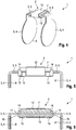
- Einander entsprechende Teile sind in allen Figuren mit den gleichen Bezugszeichen versehen.
- Ausführungsbeispiel 1 (
Fig. 1 - 3 ): Hier zeigen - Fig. 1
- Explosionsdarstellung der Basis
- Fig. 2
- perspektivische Darstellung der Basis mit Blick auf eine Deckfläche
- Fig. 3
- perspektivische Darstellung der Basis mit Blick auf einen Boden
- Beschreibung des Ausführungsbeispiels: Basis gebildet aus
- Ferritkern mit voneinander getrennten, jeweils zu einer Stirnseite offenen Vertiefungen zur Einführung jeweils einer Lasche eines der beiden Folienzuschnitte (der Steg zwischen Vertiefungen zwingt den Magnetfluss hierbei durch den Ferritkern, wodurch eine günstige magnetische Ankopplung der Antennenflächen an den Ferritkern bewirkt wird),
- einer bodenseitigen (von den Vertiefung abgewandten) PCB zum Verlöten der Antennenwicklung,
- einer die Vertiefungen abdeckenden Deckschicht (PCB, PTFE-Folie, etc.), und
- der um den Ferritkern, die PCB und die Deckschicht gewickelte Antennenwicklung, mit PCB im Reflow-Verfahren verlötet
- Die hier nicht gezeigten Folienzuschnitte sind ausgebildet, wie in den
Fig. 4 und10 gezeigt (kreisförmige Antennenflächen mit jeweils einer davon randseitig abstehenden Lasche), und werden mit den Laschen in die stirnseitigen Öffnungen der Basis eingesteckt. - Ausführungsbeispiel 2 (
Fig. 4 - 6 ): Hier zeigen - Fig. 4
- perspektivische Darstellung der MI-Antenne mit Basis und zwei Folienzuschnitten aus magnetischer Folie (mit innenseitigen diamagnetischen Schichten aus Kupfer zur magnetischen Abschirmung des zwischen den Folienzuschnitten gebildeten Innenraums) im montierten Zustand
- Fig. 5
- Seitenansicht der MI-Antenne im montierten Zustand
- Fig. 6
- Längsschnitt der MI-Antenne im montierten Zustand
- Basis gebildet aus
- Kunststoffträger mit ringförmig geschlossenen stirnseitigen Bügeln zur Einführung jeweils einer Lasche eines der beiden Folienzuschnitte und einem offenen Mittelbereich,
- einem Ferritkern, der in den offenen Mittelbereich des Trägers eingelegt ist, so dass er an den auf Stoß aneinanderliegenden Laschen der Folienzuschnitte flächig anliegt,
- einer bodenseitigen (von den Vertiefung abgewandten) PCB oder leitfähigen Beschichtung des Trägers zum Verlöten der Antennenwicklung, und
- der um den Träger und den Ferritkern (sowie ggf. die PCB) gewickelten Antennenwicklung
- Ausführungsbeispiel 3 (
Fig. 7 - 9 ): Hier zeigen - Fig. 7
- Explosionsdarstellung der Basis
- Fig. 8
- perspektivische Darstellung der Basis mit Blick auf eine Deckfläche
- Fig. 9
- perspektivische Darstellung der Basis mit Blick auf einen Boden
- Basis gebildet aus
- Ferritkern mit einer von Stirnseite zu Stirnseite durchgehenden Vertiefung zur Einführung der Laschen beider Folienzuschnitte (die Laschen liegen in dieser Vertiefung auf Stoß aneinander an),
- einer um den Ferritkern herumgefalteten PCB zum Verlöten der Antennenwicklung und zur Abdeckung der Vertiefung, und
- der um den Ferritkern und die PCB gewickelten Antennenwicklung
- Die hier nicht gezeigten Folienzuschnitte sind ausgebildet, wie in den
Fig. 4 und10 gezeigt (kreisförmige Antennenflächen mit jeweils einer davon randseitig abstehenden Lasche), und werden mit den Laschen in die stirnseitigen Öffnungen der Basis eingesteckt. - Ausführungsbeispiel 4 (
Fig. 10 und 11 ): Hier zeigen - Fig. 10
- Explosionsdarstellung der MI-Antenne mit Basis und zwei Folienzuschnitten
- Fig. 11
- Längsschnitt der MI-Antenne im montierten Zustand
- Basis gebildet aus
- hohlem Ferritkern, in dem die Laschen überlappend und flächig aneinander anliegen, und
- der um den Ferritkern gewickelten Antennenwicklung
- Im montierten Zustand liegen die diamagnetischen Kupferschichten an den Antennenflächen an, wie in
Fig. 4-6 und11 gezeigt. - Ausführungsbeispiel 5 (analog
Fig. 10 und 11 ): wie Ausführungsbeispiel 4, aber mit Kunststoffträger statt hohlem Ferritkern
Ausführungsbeispiel 6 (ohne Zeichnung): wie Ausführungsbeispiel 4, aber die Laschen liegen im Inneren des hohlen Ferritkerns auf Stoß aneinander an. - Ausführungsbeispiel 7 (ohne Zeichnung): wie Ausführungsbeispiel 4, 5 oder 6, aber die Laschen sind im Inneren des hohlen Ferritkerns oder Kunststoffträgers durch stirnseitig eingeschobene Keile verklemmt.
- Die MI-Antenne wird bevorzugt in einem Hörinstrument eingesetzt, das ein Umgebungsgeräusch aufnimmt und in bearbeiteter, insbesondere verstärkter Form in das Ohr einer das Hörinstrument tragenden Person abgibt. Die MI-Antenne ist dabei insbesondere zum Einsatz in einem Hörgerät vorgesehen, also einem Hörinstrument, das der Versorgung hörgeschädigter Personen dient. In dem Hörinstrument wird die MI-Antenne vor allem zur drahtlosen Datenübertragung mit einem Peripheriegerät, z. B. einem weiteren Hörinstrument für das andere Ohr, einer Fernbedienung etc. genutzt.
- Alternativ oder zusätzlich wird die erfindungsgemäße MI-Antenne als Ladespule zur induktiven und drahtlosen Energieübertragung von einem nicht weiter dargestellten Ladegerät an das Hörinstrument herangezogen.
- Alle Ausführungsbeispiele sind nach dem erfindungsgemäßen Verfahren hergestellt.
-
- 1
- MI-Antenne
- 2
- Basis
- 3
- Folienzuschnitt
- 4
- Antennenfläche
- 5
- Lasche
- 6
- diamagnetische Schicht aus Kupfer
- 7
- Ferritkern
- 8
- Vertiefung im Ferritkern (zur Aufnahme einer Lasche oder zweier Laschen)
- 9
- Deckfolie
- 10
- PCB
- 11
- Kontaktfläche zur Kontaktierung der Antennenwicklung (aufgedruckte Leiterbahn)
- 12
- Antennenwicklung
- 13
- (Wicklungs-)Träger (Kunststoff)
- 14
- Bügel (des Trägers)
- 15
- Kontaktfläche zur Kontaktierung der Antennenwicklung (durch leitfähige Beschichtung auf den Träger aufgebracht)
- 16
- Stirnseite
- 17
- Öffnung
Claims (11)
- Magnetisch-induktive Antenne (1) für ein Hörinstrument, mit zwei Antennenflächen (4), die aus magnetischer, flexibler Folie gebildet sind, sowie mit einer mit einer Antennenwicklung (12) bewickelten Basis (2), wobei die Antennenflächen (4) aus voneinander getrennten magnetischen Folienzuschnitten (3) gebildet sind, und wobei die Basis (2) an ihren Stirnseiten (16) jeweils eine Öffnung (17) aufweist, in die jeweils einer der Folienzuschnitte (3) eingesteckt ist.
- Antenne (1) nach Anspruch 1,
wobei die Basis (2) aus einem hohlem (insbesondere einstückigen) Grundkörper, vorzugsweise einem Ferritkern (7) oder einem Träger (13) aus nicht-magnetischem Material, z.B. Kunststoff oder Keramik, gebildet ist, in den die beiden Folienzuschnitte (3) derart eingesteckt sind, dass sie sich im Inneren des Grundkörpers überlappen oder auf Stoß aneinander anliegen. - Antenne (1) nach Anspruch 2,
wobei die Folienzuschnitte (3) in dem Grundkörper durch stirnseitig in die Öffnungen (17) eingeführte Keile verklemmt sind. - Antenne (1) nach einem der Ansprüche 1 bis 3,
wobei die Basis (2) einen Träger (13) aus nicht-magnetischem Material, z.B. Kunststoff oder Keramik, und einen Ferritkern (7) umfasst, wobei die Folienzuschnitte (3) zwischen dem Träger (13) und dem Ferritkern (7) eingelegt sind. - Antenne (1) nach einem der Ansprüche 2 bis 4,
wobei die Basis (2) zum elektrischen Anschluss der Antennenwicklung (12) einen (vorzugsweise flexiblen) gedruckten Schaltungsträger (10) umfasst, der einseitig an den Ferritkern (7) oder Träger (13) angelegt oder um den Ferritkern (7) oder Träger (13) herumgefaltet ist. - Antenne (1) nach einem der Ansprüche 2 bis 4,
wobei der Ferritkern (7) oder Träger (13) mit elektrischen Kontaktflächen (11) zur Kontaktierung der Antennenwicklung (12) beschichtet ist. - Antenne (1) nach einem der Ansprüche 2 bis 6,
wobei der Ferritkern (7) mit mindestens einer zu mindestens einer Stirnseite (16) offenen Vertiefung (8) zur Aufnahme einer Lasche (5) eines der Folienzuschnitte (3) aufweist, und wobei die Basis (2) zusätzlich eine Deckschicht (9) aufweist, die die mindestens eine Vertiefung (8) abdeckt. - Antenne (1) nach Ansprüche 7,
wobei der Ferritkern (7) zwei voneinander durch einem Steg getrennte Vertiefungen (8) zur Aufnahme jeweils einer Lasche (5) aufweist. - Hörinstrument, insbesondere Hörgerät, mit einer Antenne (1) nach einem der Ansprüche 1 bis 8.
- Verfahren zur Herstellung einer magnetisch induktiven Antenne (1) für ein Hörinstrument,• wobei in einem ersten Schritt eine mit einer Antennenwicklung (12) bewickelte Basis (2) hergestellt wird, so dass an den Stirnseiten (16) dieser Basis (2) Öffnungen (17) freigelassen sind,• wobei in einem zweiten Schritt zwei Antennenflächen (4) als voneinander getrennte Folienzuschnitte (3) aus magnetischer Folie hergestellt werden, und• wobei in einem dritten Schritt die Folienzuschnitte (3) mit der Basis (2) verbunden werden, indem jeder der beiden Folienzuschnitte (3) in eine der Öffnungen (17) der Basis (2) eingesteckt werden.
- Verfahren nach Anspruch 10,
wobei in dem ersten Schritt die Antennenwicklung (12) mit korrespondierenden Kontaktflächen (11) auf der Basis (2) verlötet wird.
Applications Claiming Priority (1)
| Application Number | Priority Date | Filing Date | Title |
|---|---|---|---|
| DE102018214199.1A DE102018214199B3 (de) | 2018-08-22 | 2018-08-22 | Performante magnetisch induktive Antenne für ein Hörinstrument |
Publications (2)
| Publication Number | Publication Date |
|---|---|
| EP3614494A1 true EP3614494A1 (de) | 2020-02-26 |
| EP3614494B1 EP3614494B1 (de) | 2021-05-05 |
Family
ID=67253710
Family Applications (1)
| Application Number | Title | Priority Date | Filing Date |
|---|---|---|---|
| EP19185643.4A Active EP3614494B1 (de) | 2018-08-22 | 2019-07-11 | Performante magnetisch induktive antenne für ein hörinstrument |
Country Status (5)
| Country | Link |
|---|---|
| US (1) | US11183762B2 (de) |
| EP (1) | EP3614494B1 (de) |
| CN (1) | CN110858947B (de) |
| DE (1) | DE102018214199B3 (de) |
| DK (1) | DK3614494T3 (de) |
Cited By (2)
| Publication number | Priority date | Publication date | Assignee | Title |
|---|---|---|---|---|
| WO2022167596A1 (de) | 2021-02-05 | 2022-08-11 | Sivantos Pte. Ltd. | Platzsparende mi-antenne für ein hörinstrument |
| DE102021214085A1 (de) | 2021-12-09 | 2023-06-15 | Sivantos Pte. Ltd. | Platzsparende Antenne für ein Hörinstrument |
Families Citing this family (1)
| Publication number | Priority date | Publication date | Assignee | Title |
|---|---|---|---|---|
| DE102019217861B3 (de) | 2019-11-20 | 2021-05-20 | Sivantos Pte. Ltd. | Hörgerät |
Citations (3)
| Publication number | Priority date | Publication date | Assignee | Title |
|---|---|---|---|---|
| US20070132648A1 (en) * | 2005-12-08 | 2007-06-14 | Kazuaki Abe | Antenna device and electronic equipment comprising the antenna device |
| EP1906270A2 (de) * | 2006-09-29 | 2008-04-02 | Casio Computer Co., Ltd. | Elektronische Vorrichtung und Uhr |
| WO2017153274A1 (de) | 2016-03-07 | 2017-09-14 | Sivantos Pte. Ltd. | Antenne |
Family Cites Families (10)
| Publication number | Priority date | Publication date | Assignee | Title |
|---|---|---|---|---|
| DE102005026410B4 (de) | 2005-06-08 | 2007-06-21 | Vacuumschmelze Gmbh & Co. Kg | Anordnung mit einem induktiven Bauelement |
| JP4905506B2 (ja) * | 2009-06-22 | 2012-03-28 | 株式会社村田製作所 | アンテナ装置 |
| DK2458675T3 (en) * | 2010-10-12 | 2018-01-22 | Gn Hearing As | Hearing aid with antenna |
| DK2932560T4 (da) * | 2012-12-12 | 2020-12-14 | Sivantos Pte Ltd | Foldet dipol til hørehjælpeapparat |
| US9635475B2 (en) * | 2013-05-01 | 2017-04-25 | Starkey Laboratories, Inc. | Hearing assistance device with balanced feed-line for antenna |
| US9191757B2 (en) * | 2013-07-11 | 2015-11-17 | Starkey Laboratories, Inc. | Hearing aid with inductively coupled electromagnetic resonator antenna |
| US9609443B2 (en) | 2015-07-21 | 2017-03-28 | Gn Hearing A/S | In-the-ear hearing aid having combined antennas |
| US10320086B2 (en) | 2016-05-04 | 2019-06-11 | Nxp B.V. | Near-field electromagnetic induction (NFEMI) antenna |
| DE102016222323A1 (de) | 2016-11-14 | 2018-05-17 | Sivantos Pte. Ltd. | Hörhilfegerät mit Elektronikrahmen und darin integrierter Antenne |
| EP3471201B1 (de) * | 2017-10-16 | 2021-02-17 | Widex A/S | Antenne für eine hörhilfevorrichtung |
-
2018
- 2018-08-22 DE DE102018214199.1A patent/DE102018214199B3/de not_active Expired - Fee Related
-
2019
- 2019-07-11 EP EP19185643.4A patent/EP3614494B1/de active Active
- 2019-07-11 DK DK19185643.4T patent/DK3614494T3/da active
- 2019-08-21 CN CN201910772121.0A patent/CN110858947B/zh active Active
- 2019-08-22 US US16/548,105 patent/US11183762B2/en active Active
Patent Citations (3)
| Publication number | Priority date | Publication date | Assignee | Title |
|---|---|---|---|---|
| US20070132648A1 (en) * | 2005-12-08 | 2007-06-14 | Kazuaki Abe | Antenna device and electronic equipment comprising the antenna device |
| EP1906270A2 (de) * | 2006-09-29 | 2008-04-02 | Casio Computer Co., Ltd. | Elektronische Vorrichtung und Uhr |
| WO2017153274A1 (de) | 2016-03-07 | 2017-09-14 | Sivantos Pte. Ltd. | Antenne |
Cited By (2)
| Publication number | Priority date | Publication date | Assignee | Title |
|---|---|---|---|---|
| WO2022167596A1 (de) | 2021-02-05 | 2022-08-11 | Sivantos Pte. Ltd. | Platzsparende mi-antenne für ein hörinstrument |
| DE102021214085A1 (de) | 2021-12-09 | 2023-06-15 | Sivantos Pte. Ltd. | Platzsparende Antenne für ein Hörinstrument |
Also Published As
| Publication number | Publication date |
|---|---|
| EP3614494B1 (de) | 2021-05-05 |
| DE102018214199B3 (de) | 2020-01-30 |
| US11183762B2 (en) | 2021-11-23 |
| CN110858947B (zh) | 2021-07-27 |
| CN110858947A (zh) | 2020-03-03 |
| US20200068326A1 (en) | 2020-02-27 |
| DK3614494T3 (da) | 2021-07-12 |
Similar Documents
| Publication | Publication Date | Title |
|---|---|---|
| EP3413587B1 (de) | Hörgerät, insbesondere hinter-dem-ohr-hörhilfegerät | |
| EP3579336B1 (de) | Antenne sowie gerät mit einer solchen antenne | |
| EP2894880B1 (de) | Antenneneinrichtung für Hörinstrumente | |
| EP3567672B1 (de) | Hörhilfegerät mit elektronikrahmen und darin integrierter antenne | |
| EP3614494B1 (de) | Performante magnetisch induktive antenne für ein hörinstrument | |
| DE102016222323A1 (de) | Hörhilfegerät mit Elektronikrahmen und darin integrierter Antenne | |
| DE102021201095A1 (de) | Platzsparende Antenne für ein Hörinstrument | |
| DE102008045668B4 (de) | Hörhilfe mit Dämpfungselement | |
| EP3809723A1 (de) | Hörinstrument | |
| EP3836565B1 (de) | Leiterplatte eines hörgeräts | |
| EP0660642B1 (de) | Am Kopf tragbares Hörgerät | |
| DE102017012195B4 (de) | Hörgerät, insbesondere Hinter-dem-Ohr-Hörhilfegerät | |
| EP4104458B1 (de) | Platzsparende mi-antenne für ein hörinstrument | |
| WO2021099038A1 (de) | Verfahren zur herstellung eines hörgeräts sowie hörgerät | |
| DE102021214085B4 (de) | Platzsparende Antenne für ein Hörinstrument | |
| DE102017210448B3 (de) | Hörgerät | |
| EP4250771B1 (de) | Hörgerät | |
| DE102020213427A1 (de) | Ladesystem sowie Ladevorrichtung für ein Hörgerät | |
| DE102014203169A1 (de) | Antenne mit Schirmvorrichtung und Herstellungsverfahren | |
| EP3739906A1 (de) | Hörinstrument | |
| DE102017220187A1 (de) | Hörhilfegerät | |
| EP2852182A1 (de) | Hörinstrument mit Batteriefachschalter | |
| DE102014219017A1 (de) | Hörinstrument mit Energieversorgungseinrichtung und Hörinstrumentensystem mit Energieversorgungseinrichtung | |
| EP3863304A1 (de) | Hörgerät mit induktiv gekoppelter antenneneinheit | |
| DE102018201025A1 (de) | Hörgerät |
Legal Events
| Date | Code | Title | Description |
|---|---|---|---|
| PUAI | Public reference made under article 153(3) epc to a published international application that has entered the european phase |
Free format text: ORIGINAL CODE: 0009012 |
|
| STAA | Information on the status of an ep patent application or granted ep patent |
Free format text: STATUS: THE APPLICATION HAS BEEN PUBLISHED |
|
| AK | Designated contracting states |
Kind code of ref document: A1 Designated state(s): AL AT BE BG CH CY CZ DE DK EE ES FI FR GB GR HR HU IE IS IT LI LT LU LV MC MK MT NL NO PL PT RO RS SE SI SK SM TR |
|
| AX | Request for extension of the european patent |
Extension state: BA ME |
|
| STAA | Information on the status of an ep patent application or granted ep patent |
Free format text: STATUS: REQUEST FOR EXAMINATION WAS MADE |
|
| 17P | Request for examination filed |
Effective date: 20200814 |
|
| RBV | Designated contracting states (corrected) |
Designated state(s): AL AT BE BG CH CY CZ DE DK EE ES FI FR GB GR HR HU IE IS IT LI LT LU LV MC MK MT NL NO PL PT RO RS SE SI SK SM TR |
|
| GRAP | Despatch of communication of intention to grant a patent |
Free format text: ORIGINAL CODE: EPIDOSNIGR1 |
|
| STAA | Information on the status of an ep patent application or granted ep patent |
Free format text: STATUS: GRANT OF PATENT IS INTENDED |
|
| INTG | Intention to grant announced |
Effective date: 20201105 |
|
| GRAS | Grant fee paid |
Free format text: ORIGINAL CODE: EPIDOSNIGR3 |
|
| RIN1 | Information on inventor provided before grant (corrected) |
Inventor name: KUHN, JOHANNES Inventor name: NIKLES, PETER |
|
| GRAA | (expected) grant |
Free format text: ORIGINAL CODE: 0009210 |
|
| STAA | Information on the status of an ep patent application or granted ep patent |
Free format text: STATUS: THE PATENT HAS BEEN GRANTED |
|
| AK | Designated contracting states |
Kind code of ref document: B1 Designated state(s): AL AT BE BG CH CY CZ DE DK EE ES FI FR GB GR HR HU IE IS IT LI LT LU LV MC MK MT NL NO PL PT RO RS SE SI SK SM TR |
|
| REG | Reference to a national code |
Ref country code: GB Ref legal event code: FG4D Free format text: NOT ENGLISH |
|
| REG | Reference to a national code |
Ref country code: CH Ref legal event code: EP |
|
| REG | Reference to a national code |
Ref country code: AT Ref legal event code: REF Ref document number: 1390979 Country of ref document: AT Kind code of ref document: T Effective date: 20210515 |
|
| REG | Reference to a national code |
Ref country code: DE Ref legal event code: R096 Ref document number: 502019001356 Country of ref document: DE |
|
| REG | Reference to a national code |
Ref country code: IE Ref legal event code: FG4D Free format text: LANGUAGE OF EP DOCUMENT: GERMAN |
|
| REG | Reference to a national code |
Ref country code: DK Ref legal event code: T3 Effective date: 20210706 |
|
| REG | Reference to a national code |
Ref country code: LT Ref legal event code: MG9D |
|
| PG25 | Lapsed in a contracting state [announced via postgrant information from national office to epo] |
Ref country code: HR Free format text: LAPSE BECAUSE OF FAILURE TO SUBMIT A TRANSLATION OF THE DESCRIPTION OR TO PAY THE FEE WITHIN THE PRESCRIBED TIME-LIMIT Effective date: 20210505 Ref country code: LT Free format text: LAPSE BECAUSE OF FAILURE TO SUBMIT A TRANSLATION OF THE DESCRIPTION OR TO PAY THE FEE WITHIN THE PRESCRIBED TIME-LIMIT Effective date: 20210505 Ref country code: FI Free format text: LAPSE BECAUSE OF FAILURE TO SUBMIT A TRANSLATION OF THE DESCRIPTION OR TO PAY THE FEE WITHIN THE PRESCRIBED TIME-LIMIT Effective date: 20210505 Ref country code: BG Free format text: LAPSE BECAUSE OF FAILURE TO SUBMIT A TRANSLATION OF THE DESCRIPTION OR TO PAY THE FEE WITHIN THE PRESCRIBED TIME-LIMIT Effective date: 20210805 |
|
| PG25 | Lapsed in a contracting state [announced via postgrant information from national office to epo] |
Ref country code: PT Free format text: LAPSE BECAUSE OF FAILURE TO SUBMIT A TRANSLATION OF THE DESCRIPTION OR TO PAY THE FEE WITHIN THE PRESCRIBED TIME-LIMIT Effective date: 20210906 Ref country code: SE Free format text: LAPSE BECAUSE OF FAILURE TO SUBMIT A TRANSLATION OF THE DESCRIPTION OR TO PAY THE FEE WITHIN THE PRESCRIBED TIME-LIMIT Effective date: 20210505 Ref country code: RS Free format text: LAPSE BECAUSE OF FAILURE TO SUBMIT A TRANSLATION OF THE DESCRIPTION OR TO PAY THE FEE WITHIN THE PRESCRIBED TIME-LIMIT Effective date: 20210505 Ref country code: LV Free format text: LAPSE BECAUSE OF FAILURE TO SUBMIT A TRANSLATION OF THE DESCRIPTION OR TO PAY THE FEE WITHIN THE PRESCRIBED TIME-LIMIT Effective date: 20210505 Ref country code: NO Free format text: LAPSE BECAUSE OF FAILURE TO SUBMIT A TRANSLATION OF THE DESCRIPTION OR TO PAY THE FEE WITHIN THE PRESCRIBED TIME-LIMIT Effective date: 20210805 Ref country code: PL Free format text: LAPSE BECAUSE OF FAILURE TO SUBMIT A TRANSLATION OF THE DESCRIPTION OR TO PAY THE FEE WITHIN THE PRESCRIBED TIME-LIMIT Effective date: 20210505 Ref country code: IS Free format text: LAPSE BECAUSE OF FAILURE TO SUBMIT A TRANSLATION OF THE DESCRIPTION OR TO PAY THE FEE WITHIN THE PRESCRIBED TIME-LIMIT Effective date: 20210905 Ref country code: GR Free format text: LAPSE BECAUSE OF FAILURE TO SUBMIT A TRANSLATION OF THE DESCRIPTION OR TO PAY THE FEE WITHIN THE PRESCRIBED TIME-LIMIT Effective date: 20210806 |
|
| REG | Reference to a national code |
Ref country code: NL Ref legal event code: MP Effective date: 20210505 |
|
| PG25 | Lapsed in a contracting state [announced via postgrant information from national office to epo] |
Ref country code: NL Free format text: LAPSE BECAUSE OF FAILURE TO SUBMIT A TRANSLATION OF THE DESCRIPTION OR TO PAY THE FEE WITHIN THE PRESCRIBED TIME-LIMIT Effective date: 20210505 |
|
| PG25 | Lapsed in a contracting state [announced via postgrant information from national office to epo] |
Ref country code: SK Free format text: LAPSE BECAUSE OF FAILURE TO SUBMIT A TRANSLATION OF THE DESCRIPTION OR TO PAY THE FEE WITHIN THE PRESCRIBED TIME-LIMIT Effective date: 20210505 Ref country code: EE Free format text: LAPSE BECAUSE OF FAILURE TO SUBMIT A TRANSLATION OF THE DESCRIPTION OR TO PAY THE FEE WITHIN THE PRESCRIBED TIME-LIMIT Effective date: 20210505 Ref country code: ES Free format text: LAPSE BECAUSE OF FAILURE TO SUBMIT A TRANSLATION OF THE DESCRIPTION OR TO PAY THE FEE WITHIN THE PRESCRIBED TIME-LIMIT Effective date: 20210505 Ref country code: SM Free format text: LAPSE BECAUSE OF FAILURE TO SUBMIT A TRANSLATION OF THE DESCRIPTION OR TO PAY THE FEE WITHIN THE PRESCRIBED TIME-LIMIT Effective date: 20210505 Ref country code: RO Free format text: LAPSE BECAUSE OF FAILURE TO SUBMIT A TRANSLATION OF THE DESCRIPTION OR TO PAY THE FEE WITHIN THE PRESCRIBED TIME-LIMIT Effective date: 20210505 Ref country code: CZ Free format text: LAPSE BECAUSE OF FAILURE TO SUBMIT A TRANSLATION OF THE DESCRIPTION OR TO PAY THE FEE WITHIN THE PRESCRIBED TIME-LIMIT Effective date: 20210505 |
|
| REG | Reference to a national code |
Ref country code: DE Ref legal event code: R097 Ref document number: 502019001356 Country of ref document: DE |
|
| PLBE | No opposition filed within time limit |
Free format text: ORIGINAL CODE: 0009261 |
|
| STAA | Information on the status of an ep patent application or granted ep patent |
Free format text: STATUS: NO OPPOSITION FILED WITHIN TIME LIMIT |
|
| PG25 | Lapsed in a contracting state [announced via postgrant information from national office to epo] |
Ref country code: MC Free format text: LAPSE BECAUSE OF FAILURE TO SUBMIT A TRANSLATION OF THE DESCRIPTION OR TO PAY THE FEE WITHIN THE PRESCRIBED TIME-LIMIT Effective date: 20210505 |
|
| REG | Reference to a national code |
Ref country code: BE Ref legal event code: MM Effective date: 20210731 |
|
| 26N | No opposition filed |
Effective date: 20220208 |
|
| PG25 | Lapsed in a contracting state [announced via postgrant information from national office to epo] |
Ref country code: IS Free format text: LAPSE BECAUSE OF FAILURE TO SUBMIT A TRANSLATION OF THE DESCRIPTION OR TO PAY THE FEE WITHIN THE PRESCRIBED TIME-LIMIT Effective date: 20210905 Ref country code: LU Free format text: LAPSE BECAUSE OF NON-PAYMENT OF DUE FEES Effective date: 20210711 Ref country code: AL Free format text: LAPSE BECAUSE OF FAILURE TO SUBMIT A TRANSLATION OF THE DESCRIPTION OR TO PAY THE FEE WITHIN THE PRESCRIBED TIME-LIMIT Effective date: 20210505 |
|
| PG25 | Lapsed in a contracting state [announced via postgrant information from national office to epo] |
Ref country code: IT Free format text: LAPSE BECAUSE OF FAILURE TO SUBMIT A TRANSLATION OF THE DESCRIPTION OR TO PAY THE FEE WITHIN THE PRESCRIBED TIME-LIMIT Effective date: 20210505 Ref country code: IE Free format text: LAPSE BECAUSE OF NON-PAYMENT OF DUE FEES Effective date: 20210711 Ref country code: BE Free format text: LAPSE BECAUSE OF NON-PAYMENT OF DUE FEES Effective date: 20210731 |
|
| PG25 | Lapsed in a contracting state [announced via postgrant information from national office to epo] |
Ref country code: CY Free format text: LAPSE BECAUSE OF FAILURE TO SUBMIT A TRANSLATION OF THE DESCRIPTION OR TO PAY THE FEE WITHIN THE PRESCRIBED TIME-LIMIT Effective date: 20210505 |
|
| PG25 | Lapsed in a contracting state [announced via postgrant information from national office to epo] |
Ref country code: HU Free format text: LAPSE BECAUSE OF FAILURE TO SUBMIT A TRANSLATION OF THE DESCRIPTION OR TO PAY THE FEE WITHIN THE PRESCRIBED TIME-LIMIT; INVALID AB INITIO Effective date: 20190711 |
|
| PG25 | Lapsed in a contracting state [announced via postgrant information from national office to epo] |
Ref country code: MK Free format text: LAPSE BECAUSE OF FAILURE TO SUBMIT A TRANSLATION OF THE DESCRIPTION OR TO PAY THE FEE WITHIN THE PRESCRIBED TIME-LIMIT Effective date: 20210505 |
|
| PG25 | Lapsed in a contracting state [announced via postgrant information from national office to epo] |
Ref country code: TR Free format text: LAPSE BECAUSE OF FAILURE TO SUBMIT A TRANSLATION OF THE DESCRIPTION OR TO PAY THE FEE WITHIN THE PRESCRIBED TIME-LIMIT Effective date: 20210505 |
|
| PG25 | Lapsed in a contracting state [announced via postgrant information from national office to epo] |
Ref country code: MT Free format text: LAPSE BECAUSE OF FAILURE TO SUBMIT A TRANSLATION OF THE DESCRIPTION OR TO PAY THE FEE WITHIN THE PRESCRIBED TIME-LIMIT Effective date: 20210505 |
|
| PGFP | Annual fee paid to national office [announced via postgrant information from national office to epo] |
Ref country code: GB Payment date: 20250619 Year of fee payment: 7 Ref country code: DK Payment date: 20250619 Year of fee payment: 7 |
|
| PGFP | Annual fee paid to national office [announced via postgrant information from national office to epo] |
Ref country code: FR Payment date: 20250620 Year of fee payment: 7 |
|
| REG | Reference to a national code |
Ref country code: AT Ref legal event code: MM01 Ref document number: 1390979 Country of ref document: AT Kind code of ref document: T Effective date: 20240711 |
|
| PGFP | Annual fee paid to national office [announced via postgrant information from national office to epo] |
Ref country code: DE Payment date: 20250620 Year of fee payment: 7 |
|
| PG25 | Lapsed in a contracting state [announced via postgrant information from national office to epo] |
Ref country code: AT Free format text: LAPSE BECAUSE OF NON-PAYMENT OF DUE FEES Effective date: 20240711 |
|
| PGFP | Annual fee paid to national office [announced via postgrant information from national office to epo] |
Ref country code: CH Payment date: 20250801 Year of fee payment: 7 |
|
| PGFP | Annual fee paid to national office [announced via postgrant information from national office to epo] |
Ref country code: AT Payment date: 20260410 Year of fee payment: 5 |