EP3614477B1 - Electrode assembly and battery including the same - Google Patents
Electrode assembly and battery including the same Download PDFInfo
- Publication number
- EP3614477B1 EP3614477B1 EP18884222.3A EP18884222A EP3614477B1 EP 3614477 B1 EP3614477 B1 EP 3614477B1 EP 18884222 A EP18884222 A EP 18884222A EP 3614477 B1 EP3614477 B1 EP 3614477B1
- Authority
- EP
- European Patent Office
- Prior art keywords
- electrode
- negative
- positive
- electrode assembly
- separator
- Prior art date
- Legal status (The legal status is an assumption and is not a legal conclusion. Google has not performed a legal analysis and makes no representation as to the accuracy of the status listed.)
- Active
Links
Images


Classifications
-
- H—ELECTRICITY
- H01—ELECTRIC ELEMENTS
- H01M—PROCESSES OR MEANS, e.g. BATTERIES, FOR THE DIRECT CONVERSION OF CHEMICAL ENERGY INTO ELECTRICAL ENERGY
- H01M10/00—Secondary cells; Manufacture thereof
- H01M10/04—Construction or manufacture in general
- H01M10/045—Cells or batteries with folded plate-like electrodes
-
- H—ELECTRICITY
- H01—ELECTRIC ELEMENTS
- H01M—PROCESSES OR MEANS, e.g. BATTERIES, FOR THE DIRECT CONVERSION OF CHEMICAL ENERGY INTO ELECTRICAL ENERGY
- H01M10/00—Secondary cells; Manufacture thereof
- H01M10/04—Construction or manufacture in general
- H01M10/0431—Cells with wound or folded electrodes
-
- H—ELECTRICITY
- H01—ELECTRIC ELEMENTS
- H01M—PROCESSES OR MEANS, e.g. BATTERIES, FOR THE DIRECT CONVERSION OF CHEMICAL ENERGY INTO ELECTRICAL ENERGY
- H01M10/00—Secondary cells; Manufacture thereof
- H01M10/04—Construction or manufacture in general
- H01M10/0459—Cells or batteries with folded separator between plate-like electrodes
-
- H—ELECTRICITY
- H01—ELECTRIC ELEMENTS
- H01M—PROCESSES OR MEANS, e.g. BATTERIES, FOR THE DIRECT CONVERSION OF CHEMICAL ENERGY INTO ELECTRICAL ENERGY
- H01M10/00—Secondary cells; Manufacture thereof
- H01M10/05—Accumulators with non-aqueous electrolyte
- H01M10/058—Construction or manufacture
- H01M10/0585—Construction or manufacture of accumulators having only flat construction elements, i.e. flat positive electrodes, flat negative electrodes and flat separators
-
- H—ELECTRICITY
- H01—ELECTRIC ELEMENTS
- H01M—PROCESSES OR MEANS, e.g. BATTERIES, FOR THE DIRECT CONVERSION OF CHEMICAL ENERGY INTO ELECTRICAL ENERGY
- H01M50/00—Constructional details or processes of manufacture of the non-active parts of electrochemical cells other than fuel cells, e.g. hybrid cells
- H01M50/40—Separators; Membranes; Diaphragms; Spacing elements inside cells
-
- H—ELECTRICITY
- H01—ELECTRIC ELEMENTS
- H01M—PROCESSES OR MEANS, e.g. BATTERIES, FOR THE DIRECT CONVERSION OF CHEMICAL ENERGY INTO ELECTRICAL ENERGY
- H01M50/00—Constructional details or processes of manufacture of the non-active parts of electrochemical cells other than fuel cells, e.g. hybrid cells
- H01M50/40—Separators; Membranes; Diaphragms; Spacing elements inside cells
- H01M50/46—Separators, membranes or diaphragms characterised by their combination with electrodes
-
- H—ELECTRICITY
- H01—ELECTRIC ELEMENTS
- H01M—PROCESSES OR MEANS, e.g. BATTERIES, FOR THE DIRECT CONVERSION OF CHEMICAL ENERGY INTO ELECTRICAL ENERGY
- H01M50/00—Constructional details or processes of manufacture of the non-active parts of electrochemical cells other than fuel cells, e.g. hybrid cells
- H01M50/50—Current conducting connections for cells or batteries
- H01M50/531—Electrode connections inside a battery casing
-
- H—ELECTRICITY
- H01—ELECTRIC ELEMENTS
- H01M—PROCESSES OR MEANS, e.g. BATTERIES, FOR THE DIRECT CONVERSION OF CHEMICAL ENERGY INTO ELECTRICAL ENERGY
- H01M50/00—Constructional details or processes of manufacture of the non-active parts of electrochemical cells other than fuel cells, e.g. hybrid cells
- H01M50/50—Current conducting connections for cells or batteries
- H01M50/531—Electrode connections inside a battery casing
- H01M50/538—Connection of several leads or tabs of wound or folded electrode stacks
-
- H—ELECTRICITY
- H01—ELECTRIC ELEMENTS
- H01M—PROCESSES OR MEANS, e.g. BATTERIES, FOR THE DIRECT CONVERSION OF CHEMICAL ENERGY INTO ELECTRICAL ENERGY
- H01M10/00—Secondary cells; Manufacture thereof
- H01M10/05—Accumulators with non-aqueous electrolyte
- H01M10/052—Li-accumulators
- H01M10/0525—Rocking-chair batteries, i.e. batteries with lithium insertion or intercalation in both electrodes; Lithium-ion batteries
-
- H—ELECTRICITY
- H01—ELECTRIC ELEMENTS
- H01M—PROCESSES OR MEANS, e.g. BATTERIES, FOR THE DIRECT CONVERSION OF CHEMICAL ENERGY INTO ELECTRICAL ENERGY
- H01M10/00—Secondary cells; Manufacture thereof
- H01M10/05—Accumulators with non-aqueous electrolyte
- H01M10/058—Construction or manufacture
- H01M10/0583—Construction or manufacture of accumulators with folded construction elements except wound ones, i.e. folded positive or negative electrodes or separators, e.g. with "Z"-shaped electrodes or separators
-
- H—ELECTRICITY
- H01—ELECTRIC ELEMENTS
- H01M—PROCESSES OR MEANS, e.g. BATTERIES, FOR THE DIRECT CONVERSION OF CHEMICAL ENERGY INTO ELECTRICAL ENERGY
- H01M4/00—Electrodes
- H01M4/02—Electrodes composed of, or comprising, active material
- H01M4/13—Electrodes for accumulators with non-aqueous electrolyte, e.g. for lithium-accumulators; Processes of manufacture thereof
-
- H—ELECTRICITY
- H01—ELECTRIC ELEMENTS
- H01M—PROCESSES OR MEANS, e.g. BATTERIES, FOR THE DIRECT CONVERSION OF CHEMICAL ENERGY INTO ELECTRICAL ENERGY
- H01M50/00—Constructional details or processes of manufacture of the non-active parts of electrochemical cells other than fuel cells, e.g. hybrid cells
- H01M50/50—Current conducting connections for cells or batteries
- H01M50/531—Electrode connections inside a battery casing
- H01M50/533—Electrode connections inside a battery casing characterised by the shape of the leads or tabs
-
- Y—GENERAL TAGGING OF NEW TECHNOLOGICAL DEVELOPMENTS; GENERAL TAGGING OF CROSS-SECTIONAL TECHNOLOGIES SPANNING OVER SEVERAL SECTIONS OF THE IPC; TECHNICAL SUBJECTS COVERED BY FORMER USPC CROSS-REFERENCE ART COLLECTIONS [XRACs] AND DIGESTS
- Y02—TECHNOLOGIES OR APPLICATIONS FOR MITIGATION OR ADAPTATION AGAINST CLIMATE CHANGE
- Y02E—REDUCTION OF GREENHOUSE GAS [GHG] EMISSIONS, RELATED TO ENERGY GENERATION, TRANSMISSION OR DISTRIBUTION
- Y02E60/00—Enabling technologies; Technologies with a potential or indirect contribution to GHG emissions mitigation
- Y02E60/10—Energy storage using batteries
-
- Y—GENERAL TAGGING OF NEW TECHNOLOGICAL DEVELOPMENTS; GENERAL TAGGING OF CROSS-SECTIONAL TECHNOLOGIES SPANNING OVER SEVERAL SECTIONS OF THE IPC; TECHNICAL SUBJECTS COVERED BY FORMER USPC CROSS-REFERENCE ART COLLECTIONS [XRACs] AND DIGESTS
- Y02—TECHNOLOGIES OR APPLICATIONS FOR MITIGATION OR ADAPTATION AGAINST CLIMATE CHANGE
- Y02P—CLIMATE CHANGE MITIGATION TECHNOLOGIES IN THE PRODUCTION OR PROCESSING OF GOODS
- Y02P70/00—Climate change mitigation technologies in the production process for final industrial or consumer products
- Y02P70/50—Manufacturing or production processes characterised by the final manufactured product
Definitions
- the present invention relates to a battery field, and more particularly, to an electrode assembly and a cell including the same.
- the rechargeable battery has attracted attention as a new energy source for improving an environmentally-friendly characteristic and energy efficiency in that it is possible to decrease the use of fossil fuel, which is the primary advantage, and a byproduct resulting from the use of energy is not generated at all.
- a lithium ion battery is in the limelight in various fields due to the advantages of having a higher operation voltage and a far higher energy density than the rechargeable batteries in the related art, such as Ni-MH, Ni-Cd and sulfuric acid-lead batteries, which use an aqueous electrolyte solution.
- a battery in the related art is manufactured by alternately stacking electrodes and separators by a lamination or simple stacking process.
- the process directly affects the energy density, and as a result, there may be only a small difference between the sizes of the separator and the electrode.
- a negative electrode and a positive electrode may be short-circuited to cause fire or the like.
- US 2012/058387 A1 , US 5 618 318 A , US 2018/241071 , and EP 2 833 459 A2 disclose an electrode assembly comprising an electrode having coated and uncoated portions.
- the present invention has been made in an effort to provide an electrode assembly and a battery including the same having an advantage of preventing a short circuit even though a separator contracts.
- an exemplary embodiment of the present invention provides an electrode assembly as defined in the appended set of claims, the electrode assembly includes a positive electrode having a plurality of positive patterns formed by being pattern-coated with a positive active material at a predetermined interval and including positive uncoated regions where the positive active material is not coated; a negative electrode having a plurality of negative patterns formed by being pattern-coated with a negative active material at a predetermined interval and including negative uncoated regions where the negative active material is not coated; and a separator disposed between the positive electrode and the negative electrode, in which the electrode assembly is formed in a zigzag shape by bending the positive uncoated regions and the negative uncoated regions.
- the positive electrode, the separator, and the negative electrode may be sequentially stacked, and the electrode assembly may be formed in the zigzag shape by bending the positive uncoated region and the negative uncoated region.
- the electrode assembly has a plurality of first electrode tabs, each one of the positive uncoated regions being coupled to one of the plurality of first electrode tabs; and the electrode assembly has a plurality of second electrode tabs, each one of the negative uncoated regions being coupled to one of the plurality of second electrode tabs.
- the positive electrode may be stacked on an upper surface of the separator, and the negative electrode may be stacked on a lower surface of the separator.
- the plurality of first electrode tabs and the plurality of second electrode tabs may be disposed at opposite sides to each other.
- the battery includes a plurality of cells, in which each of the plurality of cells includes an electrode assembly, the electrode assembly includes a positive electrode having a plurality of positive patterns formed by being pattern-coated with a positive active material at a predetermined interval and including positive uncoated regions where the positive active material is not coated, a negative electrode having a plurality of negative patterns formed by being pattern-coated with a negative active material at a predetermined interval and including negative uncoated regions where the negative active material is not coated, and a separator disposed between the positive electrode and the negative electrode, and the electrode assembly is formed in a zigzag shape by bending the positive uncoated regions and the negative uncoated regions.
- the positive electrode, the separator, and the negative electrode may be sequentially stacked, and the electrode assembly may be formed in the zigzag shape by bending the positive uncoated region and the negative uncoated region.
- the electrode assembly has a plurality of first electrode tabs, each one of the positive uncoated regions being coupled to one of the plurality of first electrode tabs; and the electrode assembly has a plurality of second electrode tabs, each one of the negative uncoated regions being coupled to one of the plurality of second electrode tabs.
- the positive electrode may be stacked on an upper surface of the separator, and the negative electrode may be stacked on a lower surface of the separator.
- the plurality of first electrode tabs and the plurality of second electrode tabs may be disposed at opposite sides to each other.
- an electrode assembly and a battery including the same capable of preventing a short circuit even though a separator contracts.
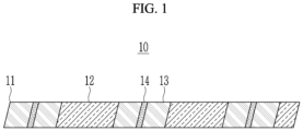
- FIG. 1 is a view illustrating a positive electrode according to an exemplary embodiment of the present invention.
- FIG. 2 is a view illustrating a negative electrode according to an exemplary embodiment of the present invention.
- FIG. 3 is a view illustrating a folding structure of an electrode assembly according to an exemplary embodiment of the present invention.
- FIGS. 1 to 3 an electrode assembly 1 according to an exemplary embodiment of the present invention will be described with reference to FIGS. 1 to 3 .
- a positive electrode 10 has a plurality of positive patterns 12 formed by pattern-coating a current collector 11 of a metal thin film shaped like a plate (for example, positive current collector) with a positive active material at a predetermined interval. Positive uncoated regions 13 where the positive active material is not coated are formed between the plurality of positive patterns 12.
- a first electrode tab (hereinafter, referred to as the "positive tab") 14 may be coupled to the positive uncoated region 13.
- a negative electrode 20 has a plurality of negative patterns formed by pattern-coating a current collector 21 of a metal thin film shaped like a plate (for example, negative current collector) with a negative active material at a predetermined interval. Negative uncoated regions 23 where the negative active material is not coated are formed between the plurality of negative patterns. A second electrode tab (hereinafter, referred to as the "negative tab") 24 may be coupled to the negative uncoated region 23.
- the positive electrode 10 is stacked on one surface of the separator 30 (for example, an upper surface of the separator 30) and the negative electrode 20 is stacked on the other surface of the separator 30 (for example, a lower surface of the separator 30), and then the electrode assembly 1 is formed in a zigzag shape by bending the positive uncoated region 13 and the negative uncoated region 23.
- the negative uncoated region 23 and the positive uncoated region 13 of the electrode assembly 1 are disposed at opposite sides to each other in a width direction of the electrode assembly 1 (a horizontal direction of FIG. 3 ).
- the negative tab 24 and the positive tab 14 coupled to the negative uncoated region 23 and the positive uncoated region 13, respectively, are positioned at the opposite sides to each other.
- the folding structure of the electrode assembly 1 having the stacking structure of the positive electrode 10/the separator 30/the negative electrode 20 has been described for the convenience of description, but the stacking order of the positive electrode, the separator 30, and the negative electrode of the present invention is not limited thereto.
- the battery according to the exemplary embodiment of the present invention includes a plurality of cells, and each of the plurality of cells includes an electrode assembly 1.
- the electrode assembly 1 includes a positive electrode 10, a separator 30, a negative electrode 20, a positive tab 14, and a negative tab.
- the positive electrode 10 has a plurality of positive patterns 12 formed by pattern-coating a positive current collector 11 shaped like a plate with a positive active material at a predetermined interval. Positive uncoated regions 13 where the positive active material is not coated are formed between the plurality of positive patterns 12. A positive tab may be coupled to the positive uncoated region 13.
- the negative electrode 20 has a plurality of negative patterns formed by pattern-coating a negative current collector 21 shaped like a plate with a negative active material at a predetermined interval. Negative uncoated regions 23 where the negative active material is not coated are formed between the plurality of negative patterns. The negative tab may be coupled to the negative uncoated region 23.
- the electrode assembly 1 of the battery according to the exemplary embodiment of the present invention to have a structure of the positive electrode 10/the separator 30/the negative electrode 20, the positive electrode 10 is stacked on an upper surface of the separator 30 and the negative electrode 20 is stacked on a lower surface of the separator 30, and then the electrode assembly 1 is formed in a zigzag shape by bending the positive uncoated region 13 and the negative uncoated region 23.
- the negative uncoated region 23 and the positive uncoated region 13 of the electrode assembly 1 of the battery according to the exemplary embodiment of the present invention are disposed at opposite sides to each other in a width direction of the electrode assembly 1.
- the negative tab and the positive tab 14 coupled to the negative uncoated region 23 and the positive uncoated region 13, respectively, are positioned at the opposite sides to each other.
Landscapes
- Chemical & Material Sciences (AREA)
- Chemical Kinetics & Catalysis (AREA)
- Electrochemistry (AREA)
- General Chemical & Material Sciences (AREA)
- Engineering & Computer Science (AREA)
- Manufacturing & Machinery (AREA)
- Materials Engineering (AREA)
- Secondary Cells (AREA)
- Battery Electrode And Active Subsutance (AREA)
- Connection Of Batteries Or Terminals (AREA)
Description
- This application claims priority to and the benefit of
Korean Patent Application No. 10-2017-0164358 filed in the Korean Intellectual Property Office on December 1, 2017 - The present invention relates to a battery field, and more particularly, to an electrode assembly and a cell including the same.
- Recently, there has been a growing interest in energy storage technology. Above all, development of a rechargeable battery capable of being easily charged/discharged has been the focus of interest. The rechargeable battery has attracted attention as a new energy source for improving an environmentally-friendly characteristic and energy efficiency in that it is possible to decrease the use of fossil fuel, which is the primary advantage, and a byproduct resulting from the use of energy is not generated at all.
- Among the rechargeable batteries widely used now, a lithium ion battery is in the limelight in various fields due to the advantages of having a higher operation voltage and a far higher energy density than the rechargeable batteries in the related art, such as Ni-MH, Ni-Cd and sulfuric acid-lead batteries, which use an aqueous electrolyte solution.
- With the development of portable electronic devices such as a mobile phone or laptop computer, demands for the rechargeable battery as an energy source thereof have sharply increased. In recent years, the use of the rechargeable battery as a power source of a hybrid electric vehicle (HEV) and an electric vehicle (EV) has been realized. Accordingly, a lot of research has been conducted on rechargeable batteries capable of meeting various demands, and particularly, demands for lithium rechargeable batteries having a high energy density, and a high discharging voltage and output are increasing.
- A battery in the related art is manufactured by alternately stacking electrodes and separators by a lamination or simple stacking process. However, the process directly affects the energy density, and as a result, there may be only a small difference between the sizes of the separator and the electrode.
- Accordingly, when there occur thermal contraction, folding, terminal tears, and the like of the battery separator, a negative electrode and a positive electrode may be short-circuited to cause fire or the like.
-
US 2012/058387 A1 ,US 5 618 318 A ,US 2018/241071 , andEP 2 833 459 A2 disclose an electrode assembly comprising an electrode having coated and uncoated portions. - The present invention has been made in an effort to provide an electrode assembly and a battery including the same having an advantage of preventing a short circuit even though a separator contracts.
- An exemplary embodiment of the present invention provides an electrode assembly as defined in the appended set of claims, the electrode assembly includes a positive electrode having a plurality of positive patterns formed by being pattern-coated with a positive active material at a predetermined interval and including positive uncoated regions where the positive active material is not coated; a negative electrode having a plurality of negative patterns formed by being pattern-coated with a negative active material at a predetermined interval and including negative uncoated regions where the negative active material is not coated; and a separator disposed between the positive electrode and the negative electrode, in which the electrode assembly is formed in a zigzag shape by bending the positive uncoated regions and the negative uncoated regions.
- Further, in the electrode assembly, the positive electrode, the separator, and the negative electrode may be sequentially stacked, and the electrode assembly may be formed in the zigzag shape by bending the positive uncoated region and the negative uncoated region.
- Further, the electrode assembly has a plurality of first electrode tabs, each one of the positive uncoated regions being coupled to one of the plurality of first electrode tabs; and the electrode assembly has a plurality of second electrode tabs, each one of the negative uncoated regions being coupled to one of the plurality of second electrode tabs.
- Further, the positive electrode may be stacked on an upper surface of the separator, and the negative electrode may be stacked on a lower surface of the separator.
- Further, the plurality of first electrode tabs and the plurality of second electrode tabs may be disposed at opposite sides to each other.
- Another exemplary embodiment of the present invention provides a battery as defined in claim 5, the battery includes a plurality of cells, in which each of the plurality of cells includes an electrode assembly, the electrode assembly includes a positive electrode having a plurality of positive patterns formed by being pattern-coated with a positive active material at a predetermined interval and including positive uncoated regions where the positive active material is not coated, a negative electrode having a plurality of negative patterns formed by being pattern-coated with a negative active material at a predetermined interval and including negative uncoated regions where the negative active material is not coated, and a separator disposed between the positive electrode and the negative electrode, and the electrode assembly is formed in a zigzag shape by bending the positive uncoated regions and the negative uncoated regions.
- Further, in the electrode assembly, the positive electrode, the separator, and the negative electrode may be sequentially stacked, and the electrode assembly may be formed in the zigzag shape by bending the positive uncoated region and the negative uncoated region.
- Further, the electrode assembly has a plurality of first electrode tabs, each one of the positive uncoated regions being coupled to one of the plurality of first electrode tabs; and the electrode assembly has a plurality of second electrode tabs, each one of the negative uncoated regions being coupled to one of the plurality of second electrode tabs.
- Further, the positive electrode may be stacked on an upper surface of the separator, and the negative electrode may be stacked on a lower surface of the separator.
- Further, the plurality of first electrode tabs and the plurality of second electrode tabs may be disposed at opposite sides to each other.
- According to the exemplary embodiments of the present invention, there are provided an electrode assembly and a battery including the same capable of preventing a short circuit even though a separator contracts.
-
-
FIG. 1 is a view illustrating a positive electrode according to an exemplary embodiment of the present invention. -
FIG. 2 is a view illustrating a negative electrode according to an exemplary embodiment of the present invention. -
FIG. 3 is a view illustrating a folding structure of an electrode assembly according to an exemplary embodiment of the present invention. -
FIG. 1 is a view illustrating a positive electrode according to an exemplary embodiment of the present invention. -
FIG. 2 is a view illustrating a negative electrode according to an exemplary embodiment of the present invention. -
FIG. 3 is a view illustrating a folding structure of an electrode assembly according to an exemplary embodiment of the present invention. - Hereinafter, an
electrode assembly 1 according to an exemplary embodiment of the present invention will be described with reference toFIGS. 1 to 3 . - Referring to
FIG. 1 , apositive electrode 10 has a plurality of positive patterns 12 formed by pattern-coating acurrent collector 11 of a metal thin film shaped like a plate (for example, positive current collector) with a positive active material at a predetermined interval. Positiveuncoated regions 13 where the positive active material is not coated are formed between the plurality of positive patterns 12. A first electrode tab (hereinafter, referred to as the "positive tab") 14 may be coupled to the positiveuncoated region 13. - Referring to
FIG. 2 , anegative electrode 20 has a plurality of negative patterns formed by pattern-coating acurrent collector 21 of a metal thin film shaped like a plate (for example, negative current collector) with a negative active material at a predetermined interval. Negativeuncoated regions 23 where the negative active material is not coated are formed between the plurality of negative patterns. A second electrode tab (hereinafter, referred to as the "negative tab") 24 may be coupled to the negativeuncoated region 23. - Referring to
FIG. 3 , in order for theelectrode assembly 1 according to the exemplary embodiment to have a structure of thepositive electrode 10/theseparator 30/thenegative electrode 20, thepositive electrode 10 is stacked on one surface of the separator 30 (for example, an upper surface of the separator 30) and thenegative electrode 20 is stacked on the other surface of the separator 30 (for example, a lower surface of the separator 30), and then theelectrode assembly 1 is formed in a zigzag shape by bending the positiveuncoated region 13 and the negativeuncoated region 23. - The negative
uncoated region 23 and the positiveuncoated region 13 of theelectrode assembly 1 are disposed at opposite sides to each other in a width direction of the electrode assembly 1 (a horizontal direction ofFIG. 3 ). Thenegative tab 24 and thepositive tab 14 coupled to the negativeuncoated region 23 and the positiveuncoated region 13, respectively, are positioned at the opposite sides to each other. - Accordingly, with the structure of the
electrode assembly 1 according to the present invention, even though the separator contracts, it is possible to prevent a short circuit. - In the foregoing, the folding structure of the
electrode assembly 1 having the stacking structure of thepositive electrode 10/theseparator 30/thenegative electrode 20 has been described for the convenience of description, but the stacking order of the positive electrode, theseparator 30, and the negative electrode of the present invention is not limited thereto. - Hereinafter, a battery including the
electrode assembly 1 according to an exemplary embodiment of the present invention will be described in detail. - The battery according to the exemplary embodiment of the present invention includes a plurality of cells, and each of the plurality of cells includes an
electrode assembly 1. - The
electrode assembly 1 includes apositive electrode 10, aseparator 30, anegative electrode 20, apositive tab 14, and a negative tab. - The
positive electrode 10 has a plurality of positive patterns 12 formed by pattern-coating a positivecurrent collector 11 shaped like a plate with a positive active material at a predetermined interval. Positiveuncoated regions 13 where the positive active material is not coated are formed between the plurality of positive patterns 12. A positive tab may be coupled to the positiveuncoated region 13. - The
negative electrode 20 has a plurality of negative patterns formed by pattern-coating a negativecurrent collector 21 shaped like a plate with a negative active material at a predetermined interval. Negativeuncoated regions 23 where the negative active material is not coated are formed between the plurality of negative patterns. The negative tab may be coupled to the negativeuncoated region 23. - In order for the
electrode assembly 1 of the battery according to the exemplary embodiment of the present invention to have a structure of thepositive electrode 10/theseparator 30/thenegative electrode 20, thepositive electrode 10 is stacked on an upper surface of theseparator 30 and thenegative electrode 20 is stacked on a lower surface of theseparator 30, and then theelectrode assembly 1 is formed in a zigzag shape by bending the positiveuncoated region 13 and the negativeuncoated region 23. - The negative
uncoated region 23 and the positiveuncoated region 13 of theelectrode assembly 1 of the battery according to the exemplary embodiment of the present invention are disposed at opposite sides to each other in a width direction of theelectrode assembly 1. The negative tab and thepositive tab 14 coupled to the negativeuncoated region 23 and the positiveuncoated region 13, respectively, are positioned at the opposite sides to each other. - Accordingly, with the structure of the
electrode assembly 1 of the battery according to the present invention, even though the separator contracts, it is possible to prevent a short circuit.
Claims (5)
- An electrode assembly, comprising:a positive electrode having a plurality of positive patterns formed by being pattern-coated with a positive active material at a predetermined interval and including positive uncoated regions where the positive active material is not coated;a negative electrode having a plurality of negative patterns formed by being pattern-coated with a negative active material at a predetermined interval and including negative uncoated regions where the negative active material is not coated; anda separator disposed between the positive electrode and the negative electrode,wherein the electrode assembly is formed in a zigzag shape by bending the positive uncoated regions and the negative uncoated regions;wherein the electrode assembly further has a plurality of first electrode tabs, each one of the positive uncoated regions being coupled to one of the plurality of first electrode tabs; and the electrode assembly further has a plurality of second electrode tabs, each one of the negative uncoated regions being coupled to one of the plurality of second electrode tabs.
- The electrode assembly of claim 1, wherein:
in the electrode assembly, the positive electrode, the separator, and the negative electrode are sequentially stacked, and the electrode assembly is formed in the zigzag shape by bending the positive uncoated regions and the negative uncoated regions. - The electrode assembly of claim 2, wherein:
the positive electrode is stacked on an upper surface of the separator, and the negative electrode is stacked on a lower surface of the separator. - The electrode assembly of claim 3, wherein:
the plurality of first electrode tabs and the plurality of second electrode tabs are disposed at opposite sides to each other. - A battery including a plurality of cells, wherein:
each of the plurality of cells includes an electrode assembly according to any one of claims 1 to 4.
Applications Claiming Priority (2)
| Application Number | Priority Date | Filing Date | Title |
|---|---|---|---|
| KR1020170164358A KR20190064977A (en) | 2017-12-01 | 2017-12-01 | Electrode assembly and battery comprising thereof |
| PCT/KR2018/013267 WO2019107776A1 (en) | 2017-12-01 | 2018-11-02 | Electrode assembly and battery comprising same |
Publications (3)
| Publication Number | Publication Date |
|---|---|
| EP3614477A1 EP3614477A1 (en) | 2020-02-26 |
| EP3614477A4 EP3614477A4 (en) | 2020-08-19 |
| EP3614477B1 true EP3614477B1 (en) | 2024-03-20 |
Family
ID=66664068
Family Applications (1)
| Application Number | Title | Priority Date | Filing Date |
|---|---|---|---|
| EP18884222.3A Active EP3614477B1 (en) | 2017-12-01 | 2018-11-02 | Electrode assembly and battery including the same |
Country Status (7)
| Country | Link |
|---|---|
| US (1) | US20200335813A1 (en) |
| EP (1) | EP3614477B1 (en) |
| KR (1) | KR20190064977A (en) |
| CN (1) | CN110521045A (en) |
| ES (1) | ES2975292T3 (en) |
| HU (1) | HUE066108T2 (en) |
| WO (1) | WO2019107776A1 (en) |
Families Citing this family (6)
| Publication number | Priority date | Publication date | Assignee | Title |
|---|---|---|---|---|
| CN112151875B (en) * | 2020-10-20 | 2022-08-09 | 深圳聚锂能源有限公司 | Current collector-free battery core, preparation method thereof and lithium ion battery |
| CN112802992B (en) * | 2020-12-30 | 2022-10-14 | 珠海冠宇电池股份有限公司 | Pole piece and lithium ion battery |
| US20220302463A1 (en) * | 2021-03-18 | 2022-09-22 | Prologium Technology Co., Ltd. | Electrode assembly and its battery device thereof |
| CN113299920B (en) * | 2021-05-24 | 2022-05-03 | 合肥国轩高科动力能源有限公司 | Lithium battery roll core |
| US12244037B2 (en) | 2021-07-09 | 2025-03-04 | Lg Energy Solution, Ltd. | Manufacturing method for electrode assembly |
| JP7838517B2 (en) * | 2023-05-12 | 2026-04-01 | トヨタ自動車株式会社 | electrode body |
Family Cites Families (14)
| Publication number | Priority date | Publication date | Assignee | Title |
|---|---|---|---|---|
| US5525441A (en) * | 1994-09-13 | 1996-06-11 | Power Conversion, Inc. | Folded electrode configuration for galvanic cells |
| KR100907623B1 (en) * | 2006-05-15 | 2009-07-15 | 주식회사 엘지화학 | Novel laminated electrode assembly for secondary battery |
| KR101156344B1 (en) * | 2009-12-07 | 2012-06-13 | 삼성에스디아이 주식회사 | Secondary battery and method for manufacturing thereof |
| KR101152515B1 (en) * | 2009-12-17 | 2012-06-01 | 삼성에스디아이 주식회사 | Electrode assembly and secondary battery using the same |
| US20110287323A1 (en) * | 2010-05-20 | 2011-11-24 | Jack Chen | Electrode and Insulator Structure for Battery and Method of Manufacture |
| KR101345349B1 (en) * | 2010-08-25 | 2013-12-27 | 주식회사 엘지화학 | Electrode Assembly of Novel Structure |
| KR101199125B1 (en) * | 2010-09-02 | 2012-11-09 | 삼성에스디아이 주식회사 | Electrode assembly including bending portions and secondary battery having the same |
| KR101439834B1 (en) * | 2012-11-08 | 2014-09-17 | 주식회사 엘지화학 | Flexible jelly roll type secondary battery |
| KR101590217B1 (en) * | 2012-11-23 | 2016-01-29 | 주식회사 엘지화학 | Method for manufacturing electorde assembly and electrode assembly manufactured thereby |
| KR101678537B1 (en) * | 2013-07-31 | 2016-11-22 | 삼성에스디아이 주식회사 | Secondary battery |
| DE102013019071A1 (en) * | 2013-11-15 | 2015-05-21 | Karlsruher Institut für Technologie | Electrode assembly, process for its preparation and electrochemical cell |
| CN203800123U (en) * | 2014-04-01 | 2014-08-27 | 广州中国科学院工业技术研究院 | Electrode assembly and lithium secondary battery |
| KR102234292B1 (en) * | 2014-04-09 | 2021-03-31 | 삼성에스디아이 주식회사 | Electrode assembly and secondary battery comprising the same |
| KR101865450B1 (en) * | 2015-06-23 | 2018-07-13 | 주식회사 엘지화학 | Electrode assembly for secondary battery, method of making the electrode assembly |
-
2017
- 2017-12-01 KR KR1020170164358A patent/KR20190064977A/en not_active Ceased
-
2018
- 2018-11-02 CN CN201880024993.2A patent/CN110521045A/en active Pending
- 2018-11-02 EP EP18884222.3A patent/EP3614477B1/en active Active
- 2018-11-02 US US16/607,979 patent/US20200335813A1/en not_active Abandoned
- 2018-11-02 WO PCT/KR2018/013267 patent/WO2019107776A1/en not_active Ceased
- 2018-11-02 HU HUE18884222A patent/HUE066108T2/en unknown
- 2018-11-02 ES ES18884222T patent/ES2975292T3/en active Active
Also Published As
| Publication number | Publication date |
|---|---|
| KR20190064977A (en) | 2019-06-11 |
| EP3614477A4 (en) | 2020-08-19 |
| CN110521045A (en) | 2019-11-29 |
| EP3614477A1 (en) | 2020-02-26 |
| WO2019107776A1 (en) | 2019-06-06 |
| HUE066108T2 (en) | 2024-07-28 |
| ES2975292T3 (en) | 2024-07-04 |
| US20200335813A1 (en) | 2020-10-22 |
Similar Documents
| Publication | Publication Date | Title |
|---|---|---|
| EP3614477B1 (en) | Electrode assembly and battery including the same | |
| US10056577B2 (en) | Battery cell of novel structure | |
| KR101792572B1 (en) | Battery Cell Having Electrode Coated with Insulating Material | |
| CN104885255B (en) | Battery cell equipped with cut out portion and the battery pack including the battery cell | |
| US9786874B2 (en) | Electrode having round corner | |
| CN109792071B (en) | Method for producing an electrode stack for a battery cell and battery cell | |
| US20150086842A1 (en) | Battery pack of irregular structure | |
| US20180083255A1 (en) | Rechargeable battery | |
| CN104040776B (en) | Secondary battery including multiple electrode assemblies | |
| US20130266845A1 (en) | Battery | |
| US11056714B2 (en) | Secondary battery | |
| KR20200099392A (en) | The Secondary Battery And The Battery Module | |
| KR102504791B1 (en) | Rechargeable battery having cover | |
| US11450906B2 (en) | Secondary cylindrical battery having piezoelectric element and thermoelectric element | |
| EP3780237A1 (en) | Unit cell and manufacturing method therefor | |
| KR101746628B1 (en) | Battery Cell Providing Suppressed Exposure of Electrode and Method for Manufacturing the Same | |
| KR20120130557A (en) | Electrode Assembly of Improved Safety And Secondary Battery with the Same | |
| EP4145585B1 (en) | Electrode assembly for secondary battery including separator with notch groove and secondary battery comprising the same | |
| KR102065369B1 (en) | Electrode Assembly Comprising Anode Having Extra Part for Improving Capacity and Battery Cell Comprising the Same | |
| KR102078801B1 (en) | Electrode assembly and manufacturing method of electrode assembly | |
| KR200394701Y1 (en) | Lithium secondary battery having anode lead and cathode lead oppositively projected from pouch | |
| KR20210117044A (en) | The Secondary Battery And The Battery Module | |
| KR20170014476A (en) | Cylindrical Secondary Battery Having Circular Electrode | |
| KR101792602B1 (en) | Battery Cell Having Electrode Assembly with Minimized Number of Reiteration of Current Collector |
Legal Events
| Date | Code | Title | Description |
|---|---|---|---|
| STAA | Information on the status of an ep patent application or granted ep patent |
Free format text: STATUS: THE INTERNATIONAL PUBLICATION HAS BEEN MADE |
|
| PUAI | Public reference made under article 153(3) epc to a published international application that has entered the european phase |
Free format text: ORIGINAL CODE: 0009012 |
|
| STAA | Information on the status of an ep patent application or granted ep patent |
Free format text: STATUS: REQUEST FOR EXAMINATION WAS MADE |
|
| 17P | Request for examination filed |
Effective date: 20191119 |
|
| AK | Designated contracting states |
Kind code of ref document: A1 Designated state(s): AL AT BE BG CH CY CZ DE DK EE ES FI FR GB GR HR HU IE IS IT LI LT LU LV MC MK MT NL NO PL PT RO RS SE SI SK SM TR |
|
| AX | Request for extension of the european patent |
Extension state: BA ME |
|
| A4 | Supplementary search report drawn up and despatched |
Effective date: 20200721 |
|
| RIC1 | Information provided on ipc code assigned before grant |
Ipc: H01M 2/26 20060101ALI20200715BHEP Ipc: H01M 4/13 20100101ALN20200715BHEP Ipc: H01M 10/0525 20100101ALN20200715BHEP Ipc: H01M 10/0583 20100101ALN20200715BHEP Ipc: H01M 10/04 20060101AFI20200715BHEP |
|
| DAV | Request for validation of the european patent (deleted) | ||
| DAX | Request for extension of the european patent (deleted) | ||
| RAP1 | Party data changed (applicant data changed or rights of an application transferred) |
Owner name: LG ENERGY SOLUTION LTD. |
|
| RAP3 | Party data changed (applicant data changed or rights of an application transferred) |
Owner name: LG ENERGY SOLUTION, LTD. |
|
| STAA | Information on the status of an ep patent application or granted ep patent |
Free format text: STATUS: EXAMINATION IS IN PROGRESS |
|
| 17Q | First examination report despatched |
Effective date: 20230713 |
|
| GRAP | Despatch of communication of intention to grant a patent |
Free format text: ORIGINAL CODE: EPIDOSNIGR1 |
|
| STAA | Information on the status of an ep patent application or granted ep patent |
Free format text: STATUS: GRANT OF PATENT IS INTENDED |
|
| RIC1 | Information provided on ipc code assigned before grant |
Ipc: H01M 50/533 20210101ALN20231206BHEP Ipc: H01M 4/13 20100101ALN20231206BHEP Ipc: H01M 10/0583 20100101ALN20231206BHEP Ipc: H01M 10/0525 20100101ALN20231206BHEP Ipc: H01M 50/40 20210101ALI20231206BHEP Ipc: H01M 10/04 20060101AFI20231206BHEP |
|
| INTG | Intention to grant announced |
Effective date: 20231220 |
|
| GRAS | Grant fee paid |
Free format text: ORIGINAL CODE: EPIDOSNIGR3 |
|
| P01 | Opt-out of the competence of the unified patent court (upc) registered |
Effective date: 20240105 |
|
| GRAA | (expected) grant |
Free format text: ORIGINAL CODE: 0009210 |
|
| STAA | Information on the status of an ep patent application or granted ep patent |
Free format text: STATUS: THE PATENT HAS BEEN GRANTED |
|
| AK | Designated contracting states |
Kind code of ref document: B1 Designated state(s): AL AT BE BG CH CY CZ DE DK EE ES FI FR GB GR HR HU IE IS IT LI LT LU LV MC MK MT NL NO PL PT RO RS SE SI SK SM TR |
|
| REG | Reference to a national code |
Ref country code: GB Ref legal event code: FG4D |
|
| REG | Reference to a national code |
Ref country code: CH Ref legal event code: EP |
|
| REG | Reference to a national code |
Ref country code: IE Ref legal event code: FG4D |
|
| REG | Reference to a national code |
Ref country code: DE Ref legal event code: R096 Ref document number: 602018067006 Country of ref document: DE |
|
| REG | Reference to a national code |
Ref country code: ES Ref legal event code: FG2A Ref document number: 2975292 Country of ref document: ES Kind code of ref document: T3 Effective date: 20240704 |
|
| PG25 | Lapsed in a contracting state [announced via postgrant information from national office to epo] |
Ref country code: LT Free format text: LAPSE BECAUSE OF FAILURE TO SUBMIT A TRANSLATION OF THE DESCRIPTION OR TO PAY THE FEE WITHIN THE PRESCRIBED TIME-LIMIT Effective date: 20240320 |
|
| REG | Reference to a national code |
Ref country code: LT Ref legal event code: MG9D |
|
| PG25 | Lapsed in a contracting state [announced via postgrant information from national office to epo] |
Ref country code: GR Free format text: LAPSE BECAUSE OF FAILURE TO SUBMIT A TRANSLATION OF THE DESCRIPTION OR TO PAY THE FEE WITHIN THE PRESCRIBED TIME-LIMIT Effective date: 20240621 |
|
| PG25 | Lapsed in a contracting state [announced via postgrant information from national office to epo] |
Ref country code: RS Free format text: LAPSE BECAUSE OF FAILURE TO SUBMIT A TRANSLATION OF THE DESCRIPTION OR TO PAY THE FEE WITHIN THE PRESCRIBED TIME-LIMIT Effective date: 20240620 Ref country code: HR Free format text: LAPSE BECAUSE OF FAILURE TO SUBMIT A TRANSLATION OF THE DESCRIPTION OR TO PAY THE FEE WITHIN THE PRESCRIBED TIME-LIMIT Effective date: 20240320 |
|
| REG | Reference to a national code |
Ref country code: NL Ref legal event code: MP Effective date: 20240320 |
|
| REG | Reference to a national code |
Ref country code: HU Ref legal event code: AG4A Ref document number: E066108 Country of ref document: HU |
|
| PG25 | Lapsed in a contracting state [announced via postgrant information from national office to epo] |
Ref country code: RS Free format text: LAPSE BECAUSE OF FAILURE TO SUBMIT A TRANSLATION OF THE DESCRIPTION OR TO PAY THE FEE WITHIN THE PRESCRIBED TIME-LIMIT Effective date: 20240620 Ref country code: NO Free format text: LAPSE BECAUSE OF FAILURE TO SUBMIT A TRANSLATION OF THE DESCRIPTION OR TO PAY THE FEE WITHIN THE PRESCRIBED TIME-LIMIT Effective date: 20240620 Ref country code: LT Free format text: LAPSE BECAUSE OF FAILURE TO SUBMIT A TRANSLATION OF THE DESCRIPTION OR TO PAY THE FEE WITHIN THE PRESCRIBED TIME-LIMIT Effective date: 20240320 Ref country code: HR Free format text: LAPSE BECAUSE OF FAILURE TO SUBMIT A TRANSLATION OF THE DESCRIPTION OR TO PAY THE FEE WITHIN THE PRESCRIBED TIME-LIMIT Effective date: 20240320 Ref country code: GR Free format text: LAPSE BECAUSE OF FAILURE TO SUBMIT A TRANSLATION OF THE DESCRIPTION OR TO PAY THE FEE WITHIN THE PRESCRIBED TIME-LIMIT Effective date: 20240621 Ref country code: FI Free format text: LAPSE BECAUSE OF FAILURE TO SUBMIT A TRANSLATION OF THE DESCRIPTION OR TO PAY THE FEE WITHIN THE PRESCRIBED TIME-LIMIT Effective date: 20240320 Ref country code: BG Free format text: LAPSE BECAUSE OF FAILURE TO SUBMIT A TRANSLATION OF THE DESCRIPTION OR TO PAY THE FEE WITHIN THE PRESCRIBED TIME-LIMIT Effective date: 20240320 |
|
| REG | Reference to a national code |
Ref country code: AT Ref legal event code: MK05 Ref document number: 1668635 Country of ref document: AT Kind code of ref document: T Effective date: 20240320 |
|
| PG25 | Lapsed in a contracting state [announced via postgrant information from national office to epo] |
Ref country code: SE Free format text: LAPSE BECAUSE OF FAILURE TO SUBMIT A TRANSLATION OF THE DESCRIPTION OR TO PAY THE FEE WITHIN THE PRESCRIBED TIME-LIMIT Effective date: 20240320 Ref country code: LV Free format text: LAPSE BECAUSE OF FAILURE TO SUBMIT A TRANSLATION OF THE DESCRIPTION OR TO PAY THE FEE WITHIN THE PRESCRIBED TIME-LIMIT Effective date: 20240320 |
|
| PG25 | Lapsed in a contracting state [announced via postgrant information from national office to epo] |
Ref country code: NL Free format text: LAPSE BECAUSE OF FAILURE TO SUBMIT A TRANSLATION OF THE DESCRIPTION OR TO PAY THE FEE WITHIN THE PRESCRIBED TIME-LIMIT Effective date: 20240320 |
|
| PG25 | Lapsed in a contracting state [announced via postgrant information from national office to epo] |
Ref country code: NL Free format text: LAPSE BECAUSE OF FAILURE TO SUBMIT A TRANSLATION OF THE DESCRIPTION OR TO PAY THE FEE WITHIN THE PRESCRIBED TIME-LIMIT Effective date: 20240320 |
|
| PG25 | Lapsed in a contracting state [announced via postgrant information from national office to epo] |
Ref country code: IS Free format text: LAPSE BECAUSE OF FAILURE TO SUBMIT A TRANSLATION OF THE DESCRIPTION OR TO PAY THE FEE WITHIN THE PRESCRIBED TIME-LIMIT Effective date: 20240720 |
|
| PG25 | Lapsed in a contracting state [announced via postgrant information from national office to epo] |
Ref country code: PT Free format text: LAPSE BECAUSE OF FAILURE TO SUBMIT A TRANSLATION OF THE DESCRIPTION OR TO PAY THE FEE WITHIN THE PRESCRIBED TIME-LIMIT Effective date: 20240722 Ref country code: SM Free format text: LAPSE BECAUSE OF FAILURE TO SUBMIT A TRANSLATION OF THE DESCRIPTION OR TO PAY THE FEE WITHIN THE PRESCRIBED TIME-LIMIT Effective date: 20240320 |
|
| PG25 | Lapsed in a contracting state [announced via postgrant information from national office to epo] |
Ref country code: CZ Free format text: LAPSE BECAUSE OF FAILURE TO SUBMIT A TRANSLATION OF THE DESCRIPTION OR TO PAY THE FEE WITHIN THE PRESCRIBED TIME-LIMIT Effective date: 20240320 Ref country code: EE Free format text: LAPSE BECAUSE OF FAILURE TO SUBMIT A TRANSLATION OF THE DESCRIPTION OR TO PAY THE FEE WITHIN THE PRESCRIBED TIME-LIMIT Effective date: 20240320 |
|
| PG25 | Lapsed in a contracting state [announced via postgrant information from national office to epo] |
Ref country code: AT Free format text: LAPSE BECAUSE OF FAILURE TO SUBMIT A TRANSLATION OF THE DESCRIPTION OR TO PAY THE FEE WITHIN THE PRESCRIBED TIME-LIMIT Effective date: 20240320 |
|
| PG25 | Lapsed in a contracting state [announced via postgrant information from national office to epo] |
Ref country code: PL Free format text: LAPSE BECAUSE OF FAILURE TO SUBMIT A TRANSLATION OF THE DESCRIPTION OR TO PAY THE FEE WITHIN THE PRESCRIBED TIME-LIMIT Effective date: 20240320 |
|
| PG25 | Lapsed in a contracting state [announced via postgrant information from national office to epo] |
Ref country code: SK Free format text: LAPSE BECAUSE OF FAILURE TO SUBMIT A TRANSLATION OF THE DESCRIPTION OR TO PAY THE FEE WITHIN THE PRESCRIBED TIME-LIMIT Effective date: 20240320 |
|
| PG25 | Lapsed in a contracting state [announced via postgrant information from national office to epo] |
Ref country code: SM Free format text: LAPSE BECAUSE OF FAILURE TO SUBMIT A TRANSLATION OF THE DESCRIPTION OR TO PAY THE FEE WITHIN THE PRESCRIBED TIME-LIMIT Effective date: 20240320 Ref country code: SK Free format text: LAPSE BECAUSE OF FAILURE TO SUBMIT A TRANSLATION OF THE DESCRIPTION OR TO PAY THE FEE WITHIN THE PRESCRIBED TIME-LIMIT Effective date: 20240320 Ref country code: RO Free format text: LAPSE BECAUSE OF FAILURE TO SUBMIT A TRANSLATION OF THE DESCRIPTION OR TO PAY THE FEE WITHIN THE PRESCRIBED TIME-LIMIT Effective date: 20240320 Ref country code: PT Free format text: LAPSE BECAUSE OF FAILURE TO SUBMIT A TRANSLATION OF THE DESCRIPTION OR TO PAY THE FEE WITHIN THE PRESCRIBED TIME-LIMIT Effective date: 20240722 Ref country code: PL Free format text: LAPSE BECAUSE OF FAILURE TO SUBMIT A TRANSLATION OF THE DESCRIPTION OR TO PAY THE FEE WITHIN THE PRESCRIBED TIME-LIMIT Effective date: 20240320 Ref country code: IS Free format text: LAPSE BECAUSE OF FAILURE TO SUBMIT A TRANSLATION OF THE DESCRIPTION OR TO PAY THE FEE WITHIN THE PRESCRIBED TIME-LIMIT Effective date: 20240720 Ref country code: EE Free format text: LAPSE BECAUSE OF FAILURE TO SUBMIT A TRANSLATION OF THE DESCRIPTION OR TO PAY THE FEE WITHIN THE PRESCRIBED TIME-LIMIT Effective date: 20240320 Ref country code: CZ Free format text: LAPSE BECAUSE OF FAILURE TO SUBMIT A TRANSLATION OF THE DESCRIPTION OR TO PAY THE FEE WITHIN THE PRESCRIBED TIME-LIMIT Effective date: 20240320 Ref country code: AT Free format text: LAPSE BECAUSE OF FAILURE TO SUBMIT A TRANSLATION OF THE DESCRIPTION OR TO PAY THE FEE WITHIN THE PRESCRIBED TIME-LIMIT Effective date: 20240320 |
|
| PG25 | Lapsed in a contracting state [announced via postgrant information from national office to epo] |
Ref country code: IT Free format text: LAPSE BECAUSE OF FAILURE TO SUBMIT A TRANSLATION OF THE DESCRIPTION OR TO PAY THE FEE WITHIN THE PRESCRIBED TIME-LIMIT Effective date: 20240320 |
|
| REG | Reference to a national code |
Ref country code: DE Ref legal event code: R097 Ref document number: 602018067006 Country of ref document: DE |
|
| PG25 | Lapsed in a contracting state [announced via postgrant information from national office to epo] |
Ref country code: IT Free format text: LAPSE BECAUSE OF FAILURE TO SUBMIT A TRANSLATION OF THE DESCRIPTION OR TO PAY THE FEE WITHIN THE PRESCRIBED TIME-LIMIT Effective date: 20240320 |
|
| PG25 | Lapsed in a contracting state [announced via postgrant information from national office to epo] |
Ref country code: DK Free format text: LAPSE BECAUSE OF FAILURE TO SUBMIT A TRANSLATION OF THE DESCRIPTION OR TO PAY THE FEE WITHIN THE PRESCRIBED TIME-LIMIT Effective date: 20240320 |
|
| PLBE | No opposition filed within time limit |
Free format text: ORIGINAL CODE: 0009261 |
|
| STAA | Information on the status of an ep patent application or granted ep patent |
Free format text: STATUS: NO OPPOSITION FILED WITHIN TIME LIMIT |
|
| PG25 | Lapsed in a contracting state [announced via postgrant information from national office to epo] |
Ref country code: DK Free format text: LAPSE BECAUSE OF FAILURE TO SUBMIT A TRANSLATION OF THE DESCRIPTION OR TO PAY THE FEE WITHIN THE PRESCRIBED TIME-LIMIT Effective date: 20240320 |
|
| 26N | No opposition filed |
Effective date: 20241223 |
|
| PG25 | Lapsed in a contracting state [announced via postgrant information from national office to epo] |
Ref country code: SI Free format text: LAPSE BECAUSE OF FAILURE TO SUBMIT A TRANSLATION OF THE DESCRIPTION OR TO PAY THE FEE WITHIN THE PRESCRIBED TIME-LIMIT Effective date: 20240320 |
|
| REG | Reference to a national code |
Ref country code: CH Ref legal event code: PL |
|
| PG25 | Lapsed in a contracting state [announced via postgrant information from national office to epo] |
Ref country code: MC Free format text: LAPSE BECAUSE OF FAILURE TO SUBMIT A TRANSLATION OF THE DESCRIPTION OR TO PAY THE FEE WITHIN THE PRESCRIBED TIME-LIMIT Effective date: 20240320 |
|
| PG25 | Lapsed in a contracting state [announced via postgrant information from national office to epo] |
Ref country code: LU Free format text: LAPSE BECAUSE OF NON-PAYMENT OF DUE FEES Effective date: 20241102 |
|
| REG | Reference to a national code |
Ref country code: CH Ref legal event code: PL |
|
| PG25 | Lapsed in a contracting state [announced via postgrant information from national office to epo] |
Ref country code: CH Free format text: LAPSE BECAUSE OF NON-PAYMENT OF DUE FEES Effective date: 20241130 |
|
| PG25 | Lapsed in a contracting state [announced via postgrant information from national office to epo] |
Ref country code: IE Free format text: LAPSE BECAUSE OF NON-PAYMENT OF DUE FEES Effective date: 20241102 |
|
| PGFP | Annual fee paid to national office [announced via postgrant information from national office to epo] |
Ref country code: HU Payment date: 20251127 Year of fee payment: 8 |
|
| PGFP | Annual fee paid to national office [announced via postgrant information from national office to epo] |
Ref country code: DE Payment date: 20251020 Year of fee payment: 8 |
|
| PGFP | Annual fee paid to national office [announced via postgrant information from national office to epo] |
Ref country code: GB Payment date: 20251023 Year of fee payment: 8 |
|
| PGFP | Annual fee paid to national office [announced via postgrant information from national office to epo] |
Ref country code: FR Payment date: 20251021 Year of fee payment: 8 |
|
| PGFP | Annual fee paid to national office [announced via postgrant information from national office to epo] |
Ref country code: BE Payment date: 20251020 Year of fee payment: 8 |
|
| PGFP | Annual fee paid to national office [announced via postgrant information from national office to epo] |
Ref country code: ES Payment date: 20251215 Year of fee payment: 8 |
|
| PG25 | Lapsed in a contracting state [announced via postgrant information from national office to epo] |
Ref country code: CY Free format text: LAPSE BECAUSE OF FAILURE TO SUBMIT A TRANSLATION OF THE DESCRIPTION OR TO PAY THE FEE WITHIN THE PRESCRIBED TIME-LIMIT; INVALID AB INITIO Effective date: 20181102 |