EP3614404A1 - Reducing reluctance in magnetic devices - Google Patents
Reducing reluctance in magnetic devices Download PDFInfo
- Publication number
- EP3614404A1 EP3614404A1 EP19192825.8A EP19192825A EP3614404A1 EP 3614404 A1 EP3614404 A1 EP 3614404A1 EP 19192825 A EP19192825 A EP 19192825A EP 3614404 A1 EP3614404 A1 EP 3614404A1
- Authority
- EP
- European Patent Office
- Prior art keywords
- core
- core segment
- spacer
- magnetic
- segment
- Prior art date
- Legal status (The legal status is an assumption and is not a legal conclusion. Google has not performed a legal analysis and makes no representation as to the accuracy of the status listed.)
- Withdrawn
Links
- 230000005291 magnetic effect Effects 0.000 title claims abstract description 110
- 125000006850 spacer group Chemical group 0.000 claims abstract description 76
- 230000004907 flux Effects 0.000 claims abstract description 58
- 239000004020 conductor Substances 0.000 claims abstract description 23
- 238000000034 method Methods 0.000 claims abstract description 15
- 238000006243 chemical reaction Methods 0.000 claims abstract description 7
- 239000012212 insulator Substances 0.000 claims description 33
- 238000004804 winding Methods 0.000 claims description 17
- 238000010276 construction Methods 0.000 claims description 15
- 229910052782 aluminium Inorganic materials 0.000 claims description 10
- 238000010438 heat treatment Methods 0.000 claims description 6
- 239000003302 ferromagnetic material Substances 0.000 claims description 5
- PMHQVHHXPFUNSP-UHFFFAOYSA-M copper(1+);methylsulfanylmethane;bromide Chemical compound Br[Cu].CSC PMHQVHHXPFUNSP-UHFFFAOYSA-M 0.000 claims description 3
- 230000001939 inductive effect Effects 0.000 claims description 3
- 238000000926 separation method Methods 0.000 claims description 3
- 230000008878 coupling Effects 0.000 claims 1
- 238000010168 coupling process Methods 0.000 claims 1
- 238000005859 coupling reaction Methods 0.000 claims 1
- 239000011162 core material Substances 0.000 description 138
- 239000000463 material Substances 0.000 description 12
- 230000035699 permeability Effects 0.000 description 10
- XAGFODPZIPBFFR-UHFFFAOYSA-N aluminium Chemical compound [Al] XAGFODPZIPBFFR-UHFFFAOYSA-N 0.000 description 4
- 239000012255 powdered metal Substances 0.000 description 4
- 229910000859 α-Fe Inorganic materials 0.000 description 3
- 238000013459 approach Methods 0.000 description 2
- 230000008859 change Effects 0.000 description 2
- 238000004891 communication Methods 0.000 description 2
- 229910000831 Steel Inorganic materials 0.000 description 1
- 239000000853 adhesive Substances 0.000 description 1
- 230000001070 adhesive effect Effects 0.000 description 1
- 230000004888 barrier function Effects 0.000 description 1
- 230000008901 benefit Effects 0.000 description 1
- 230000015572 biosynthetic process Effects 0.000 description 1
- 238000007796 conventional method Methods 0.000 description 1
- 238000010586 diagram Methods 0.000 description 1
- 230000000694 effects Effects 0.000 description 1
- 230000005294 ferromagnetic effect Effects 0.000 description 1
- 230000006870 function Effects 0.000 description 1
- 238000002955 isolation Methods 0.000 description 1
- 238000010030 laminating Methods 0.000 description 1
- 230000005415 magnetization Effects 0.000 description 1
- 238000004519 manufacturing process Methods 0.000 description 1
- 238000012986 modification Methods 0.000 description 1
- 230000004048 modification Effects 0.000 description 1
- 239000000615 nonconductor Substances 0.000 description 1
- 229920006395 saturated elastomer Polymers 0.000 description 1
- 239000010959 steel Substances 0.000 description 1
- 238000012546 transfer Methods 0.000 description 1
- 239000013585 weight reducing agent Substances 0.000 description 1
Images



Classifications
-
- H—ELECTRICITY
- H01—ELECTRIC ELEMENTS
- H01F—MAGNETS; INDUCTANCES; TRANSFORMERS; SELECTION OF MATERIALS FOR THEIR MAGNETIC PROPERTIES
- H01F27/00—Details of transformers or inductances, in general
- H01F27/08—Cooling; Ventilating
- H01F27/22—Cooling by heat conduction through solid or powdered fillings
-
- H—ELECTRICITY
- H01—ELECTRIC ELEMENTS
- H01F—MAGNETS; INDUCTANCES; TRANSFORMERS; SELECTION OF MATERIALS FOR THEIR MAGNETIC PROPERTIES
- H01F27/00—Details of transformers or inductances, in general
- H01F27/24—Magnetic cores
-
- H—ELECTRICITY
- H01—ELECTRIC ELEMENTS
- H01F—MAGNETS; INDUCTANCES; TRANSFORMERS; SELECTION OF MATERIALS FOR THEIR MAGNETIC PROPERTIES
- H01F27/00—Details of transformers or inductances, in general
- H01F27/28—Coils; Windings; Conductive connections
-
- H—ELECTRICITY
- H01—ELECTRIC ELEMENTS
- H01F—MAGNETS; INDUCTANCES; TRANSFORMERS; SELECTION OF MATERIALS FOR THEIR MAGNETIC PROPERTIES
- H01F27/00—Details of transformers or inductances, in general
- H01F27/28—Coils; Windings; Conductive connections
- H01F27/2895—Windings disposed upon ring cores
-
- H—ELECTRICITY
- H01—ELECTRIC ELEMENTS
- H01F—MAGNETS; INDUCTANCES; TRANSFORMERS; SELECTION OF MATERIALS FOR THEIR MAGNETIC PROPERTIES
- H01F27/00—Details of transformers or inductances, in general
- H01F27/34—Special means for preventing or reducing unwanted electric or magnetic effects, e.g. no-load losses, reactive currents, harmonics, oscillations, leakage fields
- H01F27/346—Preventing or reducing leakage fields
-
- H—ELECTRICITY
- H01—ELECTRIC ELEMENTS
- H01F—MAGNETS; INDUCTANCES; TRANSFORMERS; SELECTION OF MATERIALS FOR THEIR MAGNETIC PROPERTIES
- H01F3/00—Cores, Yokes, or armatures
- H01F3/10—Composite arrangements of magnetic circuits
- H01F3/14—Constrictions; Gaps, e.g. air-gaps
-
- H—ELECTRICITY
- H01—ELECTRIC ELEMENTS
- H01F—MAGNETS; INDUCTANCES; TRANSFORMERS; SELECTION OF MATERIALS FOR THEIR MAGNETIC PROPERTIES
- H01F30/00—Fixed transformers not covered by group H01F19/00
- H01F30/06—Fixed transformers not covered by group H01F19/00 characterised by the structure
- H01F30/16—Toroidal transformers
-
- H—ELECTRICITY
- H01—ELECTRIC ELEMENTS
- H01F—MAGNETS; INDUCTANCES; TRANSFORMERS; SELECTION OF MATERIALS FOR THEIR MAGNETIC PROPERTIES
- H01F37/00—Fixed inductances not covered by group H01F17/00
Definitions
- the present disclosure relates to electrical systems, and more particularly to electrical systems having inductors with gapped cores.
- Inductors are electrical devices that store energy in a magnetic field responsive to current flow through the inductor.
- the magnetic field operates to oppose change in the current flow, generally according to the inductance of the particular inductor.
- a magnetic core is provided for magnetization by the current flowing through the inductor. As the core becomes increasingly magnetized the opposition to change in current flow provided by the core increases, generally until the core becomes saturated.
- gaps such in electrical devices used to support higher currents. While gaps allow for higher current flows gaps generally lower the effective permeability of the inductor, typically resulting in lower inductance. Since lowering the effective permeability of the gap increases the losses associated with permeability of the magnetic core (as a function of the frequency of the current), gaps distance is typically selected to promote fringing, where the magnetic flux lines depart to the core on one side of the gap and return to the core on the opposite side of the gap. This increases inductance, offsetting some of the effects of the gap. However, fringing can result in radiated field cross talk in the windings proximate the gap as well as localized heating where the magnetic flux lines return to the magnetic core.
- a magnetic core for inductor includes a first core segment, a second core segment spaced apart from the first core segment by a gap, and a spacer.
- the spacer is arranged within the gap and between the first core segment and the second core segment.
- the spacer includes a semi-conductive material to limit arc radius of magnetic flux lines communicated between the first core segment and the second core segment outside the gap.
- the semi-conductive material has a relative permeability of about 1.
- the semi-conductive material can have electrical resistivity that is greater than electrical resistivity of aluminum.
- the semi-conductive material can include aluminum nitride.
- Arc radius of magnetic lines of flux entering the second core segment from the first core segment can be smaller than arc radius of magnetic flux entering the second core segment with an air spacer or aluminum spacer of substantially equivalent reluctance.
- the spacer can be electrically isolated from the first core segment.
- the spacer can be electrically isolated from the second core segment.
- An insulator can be arranged between the spacer and the first core segment.
- the insulator can be a first insulator and a second insulator can be arranged between the spacer and the second core segment.
- the spacer can be thermally grounded.
- the spacer can be thermally grounded to the chassis of an electrical device including the magnetic core, such as a flyback transformer or a transformer rectifier unit by way of example.
- the magnetic core can have a toroid shape.
- the magnetic core can be monolithic in construction.
- the magnetic core can have a layered construction.
- the first core segment and the second core segment can include a ferromagnetic material.
- a winding can extend about the first core segment, the spacer, and the second core segment. Separation between the winding and the spacer can be substantially equivalent to spacing between the winding and at least one of the first core segment and the second core segment.
- An inductor includes a magnetic core as described above.
- a first insulator is arranged between the spacer and the first core segment.
- a second insulator is arranged between the spacer and the second core segment.
- a thermal ground connects the second core segment to a heat sink through the spacer and the second insulator.
- a flyback transformer or transformer rectifier unit can include the an inductor.
- the flyback transformer or TRU can be configured and adapted to convert 120 voltage alternating current power into 28 volt direct current power.
- a power conversion method includes, at a magnetic core with a winding wrapped thereabout and a first core segment, a second core segment spaced apart from the first core segment by a gap, and a spacer including a semi-conductive material arranged in the gap and between the first and second core segments, inducing magnetic flux in the first core segment.
- the magnetic flux is communicated to the second core segment and arc radius of lines of magnetic flux returning to the second core segment limited with the semi-conductive material.
- arc radius of lines of magnetic flux returning to the second core segment from the first segment can be less than an air spacer or aluminum spacer of substantially equivalent reluctance.
- the spacer can be electrically separated from the second core segment with an insulator. Heat can be transferred from the location where the lines of magnetic flux return to the core through a heat sink thermally coupled to the second core segment by the spacer.
- FIG. 1 a partial view of an exemplary embodiment of a magnetic core with a spacer formed from a semi-conductive material in accordance with the disclosure is shown in Fig. 1 and is designated generally by reference character 100.
- Other embodiments of magnetic cores, transformer rectifier units having ferromagnetic cores with segments spaced by semi-conductive materials, and power conversion methods in accordance with the disclosure, or aspects thereof, are provided in Figs. 2-5 , as will be described.
- the systems and methods described herein can be used in magnetic cores for inductors, such as in flyback transformers or transformer rectifier units for aircraft electrical systems, though the present disclosure is not limited to aircraft electrical systems or a particular type of electrical device in general.
- Inductor 102 includes magnetic core 100.
- Magnetic core 100 includes a first core segment 104, a second core segment 106, and a spacer 108.
- Second core segment 106 is spaced apart from first core segment 104 by a gap 110 and spacer 108 is arranged with gap 110.
- Spacer 108 includes a semi-conductive material 112 (shown in Fig. 2 ) to limit arc radius 113 of magnetic flux lines M (shown in Fig. 2 ) communicated between first core segment 104 and second core segment 106 radially outward of gap 110.
- a winding 114 is wrapped about at least a portion of magnetic core 100.
- Winding 114 carries a current i, which induces magnetic flux M (shown in Fig. 2 ).
- winding 114 is part of flyback transformer 10.
- winding 114 can be part of a transformer rectifier unit (TRU) 12, such as for an aircraft electrical system.
- TRU transformer rectifier unit
- magnetic core 100 has a toroid shape 116.
- Toroid shape 116 is defined by eight (8) core segments sequentially spaced apart from one another by eight (8) spacers. This is for illustration purposes only and is non-limiting.
- magnetic core 100 can have fewer than eight segments or more than eight segments, as suitable for an intended application.
- magnetic core 100 can have another shape, such as a U-shape or an E-shape, and remain within the scope of the present disclosure.
- First core segment 104 and second core segment 106 each include a ferromagnetic material 105 (shown in Fig. 2 ).
- Spacer 108 is arranged within gap 110 between first core segment 104 and second core segment 106.
- Inductor 102 also includes a first insulator 118 and a second insulator 120.
- First insulator 118 is arranged within gap 110 between first core segment 104 and spacer 108.
- Second insulator 120 is also arranged within gap 110, and is additionally located between second core segment 106 and spacer 108.
- Winding 114 extends about first core segment 104, spacer 108, and second core segment 106.
- first insulator 118 and second insulator 120 each be formed from an insulator material 109 that is both a good electrical insulator, spacer 108 thereby being electrically isolated (i.e. electrically insulated) from first core segment 104 and second core segment 106.
- insulator material 109 is a dielectric adhesive material, which facilitates fabrication of magnetic core 100 as well as providing suitable electrical isolation.
- first insulator 118 and second insulator 120 each be formed from a material with a relatively good heat transfer coefficient for removing heat from second core segment 106, thereby limiting permeability variation due to heating as a consequence of magnetic flux M communicated radially outward from magnetic core 100 upon return to second core segment 106.
- Spacer 108 includes semi-conductive material 112.
- semi-conductive material 112 has a relative permeability of about 1. Relative permeability of about 1 enables spacer 108 to communicate sufficient flux therethrough that magnetic flux lines radiated radially outward from magnetic core 100 (illustrated schematically with a single magnetic flux 'mean' flux line 122) return to second core segment with an angle that is less than about 90 degrees. This reduces the return angle of magnetic flux lines 122, limiting so-called flux crowding in the exterior portion of second core segment 106 bounding spacer 108, and limiting localized hearing at the portion.
- semi-conductive material 112 has an electrical resistivity that is greater than electrical resistivity of aluminum, which allows gap 110 to have a relatively small gap width.
- Semi-conductive material 112 can be, for example, aluminum nitride.
- the arc radius of magnetic lines of flux entering the second core segment from the first core segment can be smaller than arc radius of magnetic flux entering the second core segment with an air spacer or aluminum spacer of substantially equivalent reluctance.
- magnetic flux lines 122 have an arc radius 124 that is smaller than an arc radius 126 of magnetic flux lines 128 of an air gap spacer or a spacer used in the magnetic core 100 for purposes providing substantially the same reluctance at gap 110.
- magnetic flux lines 122 allow for positioning winding 114 at spacer 108 with equivalent radial separation as required at first core segment 104 and second core segment 106. This is because semi-conductive material 112 reduces magnitude of magnetic flux lines 122 such that eddy current formation on winding 114 is limited, and the associated cross talk relatively small.
- magnetic core 100 is shown according to an exemplary embodiment having a monolithic construction 140.
- monolithic means that magnetic core 100 does not include stacked layers and/or laminated sheets within its respective core segments.
- ferromagnetic material 105 included in magnetic core 100 includes a material formed from ferrite or powdered metal 132.
- ferrite or powdered metal 132 As will be appreciated by those of skill in the art in view of the present disclosure, use of powdered metal eliminates the intra-segment barrier that sheet interfaces can pose to magnetic flux communication, and the associated efficiency losses due to heating at such interfaces. This is because of the homogeneity provided by the monolithic construction of magnetic core 100 when constructed using ferrite or powdered metal 132.
- inductor 102 includes a thermal ground 134 connecting second core segment 106 to a heat sink 136 through spacer 108 and second insulator 120. More particularly, thermal ground 134 is connected (i.e., thermally and electrically) directly to spacer 108. This allows heat H generated at the radially outer periphery of second core segment 106 to be communicated by second insulator 120 to spacer 108, and therethrough to heat sink 136 through thermal ground 134. Communicating heat H to heat sink 136 prevents H from locally changing permeability of magnetic core 100, which could otherwise offset at least in part the permeability homogeneity provided by ferrite or powdered metal 132.
- Heat sink 136 can be, for example, a chassis of an electrical device, such as flyback transformer 10 (shown in Fig. 1 ) or TRU 12 (shown in Fig. 1 ) by way of example.
- flyback transformer or TRU 10 is configured and adapted to convert 120 voltage alternating current power into 28 volt direct current power.
- flyback transformers and TRU device with higher or lower ratings, as well as other electrical devices can also benefit from the present disclosure due to the reduced weight of magnetic core 100 and lower operating temperature of inductor 102 associated with magnetic core 100.
- magnetic core 200 is shown according to another exemplary embodiment having a layered construction 202.
- layered means that magnetic core 200 includes wound, stacked, layered and/or laminated sheets within its respective core segments. More particularly, the ferromagnetic material 105 (shown in Fig. 2 ) included in magnetic core 100 is formed from a plurality of sheets 204. Sheets 204 can be formed from an electric steel material 206, which is amendable to stamping and laminating to form relative complex core shapes (e.g., non-toroid shaped). As will be appreciated by those of skill in the art in view of the present disclosure, use layered construction 202 can reduce the cost of fabricating magnetic core 200.
- layered construction 202 can be more sensitive to the return angle of magnetic flux lines 122 due to the interface proximate (i.e., under) the location where magnetic flux lines 122 return to second core segment 106 where the outer sheet is joined to the inner sheets. Layered construction 202 thereby aggravates the tendency of heat H to be generated at the return location.
- magnetic core 200 is also thermally grounded.
- magnetic core 200 with layered construction 202 also includes a thermal ground 210 connecting second core segment 212 to a heat sink 214 through spacer 216 and second insulator 218.
- Connectivity to heat sink 214 allows for communication of heat H to heat sink 214, preventing heat H from locally changing permeability of magnetic core 200 and potentially extending the use of layered construction 202 to applications where current flow i (shown in Fig. 1 ) could otherwise preclude the use of layered construction 202.
- Power conversion method 300 includes, at an inductor having a magnetic core, e.g., magnetic core 100 (shown in Fig. 1 ) or magnetic core 200 (shown in Fig. 4 ), inducing magnetic flux, e.g., magnetic flux M (shown in Fig. 2 ), as shown with box 310.
- the magnetic flux is communicated from the first core segment, e.g., first core segment 104 (shown in Fig. 1 ), to the second core segment 106 (shown in Fig. 1 ), shown with box 320.
- the arc radius of the magnetic flux lines is limited by the material forming the spacer located between the first core segment and the second core segment, e.g., semi-conductive material 112 (shown in Fig. 2 ), as shown with box 330.
- the magnetic flux lines have an arc radius smaller than that of an air gap having similar reluctance, as shown with box 332. It is also contemplated that the magnetic flux lines have an arc radius that is less than 90 degrees, as shown with box 334. In this respect the radius of lines of magnetic flux returning to the second core segment from the first segment can be less than an air spacer or aluminum spacer of substantially equivalent reluctance. Further, in certain embodiments, the spacer can be electrically separated from the second core segment with an insulator, as shown with box 340. Heat can be transferred from the location where the lines of magnetic flux return to the core through a heat sink thermally coupled to the second core segment by the spacer, as shown with box 350.
- Gap losses related to large fringing flux in cut toroidal inductors can cause excessive heating.
- the magnetic field radiated outward can also cause additional losses in the housing containing the inductor.
- This magnetic field is radiated radially outward due to the reluctance of air or similar gap material.
- One approach to limit the impact of fringing flux is to increase the number of gaps and make each gap relatively small in width, thereby reducing the reluctance at each gap. While generally acceptable for its intended purpose, small gaps tend to cause the fringing flux to re-enter the core material at an angle perpendicular to the core due to the gap width, resulting in heating.
- Another approach is to construct the spacer from a low reluctance material, such as aluminum. While generally acceptable, aluminum tends to develop eddy currents in the spacer, which limits the effectiveness of the spacer as energy level increases.
- a semi-conductive material is inserted into the gaps of the inductor.
- the semi-conductive material reduces the reluctance of the gap and directs the lines of flux associated with the fringing flux.
- the spacer material can have a reluctance substantially equivalent to the material forming the core, thereby limiting the arc radius of the fringing flux and causing a relatively large proportion of th magnetic flux to be communicated through the spacer rather than radially outward of the spacer. It is also contemplated that the spacer can be used to thermally shunt heat generated by the returning flux to a heat sink. This can result in both a weight reduction and lower operating temperature of the inductor owing to the use of the semi-conductive material forming the spacer.
Landscapes
- Engineering & Computer Science (AREA)
- Power Engineering (AREA)
- Chemical & Material Sciences (AREA)
- Composite Materials (AREA)
- Coils Or Transformers For Communication (AREA)
Abstract
Description
- The present disclosure relates to electrical systems, and more particularly to electrical systems having inductors with gapped cores.
- Inductors are electrical devices that store energy in a magnetic field responsive to current flow through the inductor. The magnetic field operates to oppose change in the current flow, generally according to the inductance of the particular inductor. In some applications a magnetic core is provided for magnetization by the current flowing through the inductor. As the core becomes increasingly magnetized the opposition to change in current flow provided by the core increases, generally until the core becomes saturated.
- Some cores have gaps, such in electrical devices used to support higher currents. While gaps allow for higher current flows gaps generally lower the effective permeability of the inductor, typically resulting in lower inductance. Since lowering the effective permeability of the gap increases the losses associated with permeability of the magnetic core (as a function of the frequency of the current), gaps distance is typically selected to promote fringing, where the magnetic flux lines depart to the core on one side of the gap and return to the core on the opposite side of the gap. This increases inductance, offsetting some of the effects of the gap. However, fringing can result in radiated field cross talk in the windings proximate the gap as well as localized heating where the magnetic flux lines return to the magnetic core.
- Such conventional methods and systems have generally been considered satisfactory for their intended purpose. However, there is still a need in the art for improved magnetic cores, inductors, and related methods. The present disclosure provides a solution for this need.
- A magnetic core for inductor includes a first core segment, a second core segment spaced apart from the first core segment by a gap, and a spacer. The spacer is arranged within the gap and between the first core segment and the second core segment. The spacer includes a semi-conductive material to limit arc radius of magnetic flux lines communicated between the first core segment and the second core segment outside the gap.
- In certain embodiments, the semi-conductive material has a relative permeability of about 1. The semi-conductive material can have electrical resistivity that is greater than electrical resistivity of aluminum. The semi-conductive material can include aluminum nitride. Arc radius of magnetic lines of flux entering the second core segment from the first core segment can be smaller than arc radius of magnetic flux entering the second core segment with an air spacer or aluminum spacer of substantially equivalent reluctance.
- In accordance with certain embodiments, the spacer can be electrically isolated from the first core segment. The spacer can be electrically isolated from the second core segment. An insulator can be arranged between the spacer and the first core segment. The insulator can be a first insulator and a second insulator can be arranged between the spacer and the second core segment. The spacer can be thermally grounded. The spacer can be thermally grounded to the chassis of an electrical device including the magnetic core, such as a flyback transformer or a transformer rectifier unit by way of example.
- It is also contemplated that, in accordance with certain embodiments, the magnetic core can have a toroid shape. The magnetic core can be monolithic in construction. The magnetic core can have a layered construction. The first core segment and the second core segment can include a ferromagnetic material. A winding can extend about the first core segment, the spacer, and the second core segment. Separation between the winding and the spacer can be substantially equivalent to spacing between the winding and at least one of the first core segment and the second core segment.
- An inductor includes a magnetic core as described above. A first insulator is arranged between the spacer and the first core segment. A second insulator is arranged between the spacer and the second core segment. A thermal ground connects the second core segment to a heat sink through the spacer and the second insulator. A flyback transformer or transformer rectifier unit (TRU) can include the an inductor. The flyback transformer or TRU can be configured and adapted to convert 120 voltage alternating current power into 28 volt direct current power.
- A power conversion method includes, at a magnetic core with a winding wrapped thereabout and a first core segment, a second core segment spaced apart from the first core segment by a gap, and a spacer including a semi-conductive material arranged in the gap and between the first and second core segments, inducing magnetic flux in the first core segment. The magnetic flux is communicated to the second core segment and arc radius of lines of magnetic flux returning to the second core segment limited with the semi-conductive material.
- In certain embodiments arc radius of lines of magnetic flux returning to the second core segment from the first segment can be less than an air spacer or aluminum spacer of substantially equivalent reluctance. The spacer can be electrically separated from the second core segment with an insulator. Heat can be transferred from the location where the lines of magnetic flux return to the core through a heat sink thermally coupled to the second core segment by the spacer.
- These and other features of the systems and methods of the subject disclosure will become more readily apparent to those skilled in the art from the following detailed description of the preferred embodiments taken in conjunction with the drawings.
- So that those skilled in the art to which the subject disclosure appertains will readily understand how to make and use the devices and methods of the subject disclosure without undue experimentation, embodiments thereof will be described in detail herein below with reference to certain figures, wherein:
-
Fig. 1 is a plan view of an exemplary embodiment of an inductor constructed in accordance with the present disclosure, shown a winding wrapped about a segment magnetic core with gaps between the magnetic core segments; -
Fig. 2 is a plan view of a portion of the inductor ofFig. 1 including a spacer arranged within the gap between the core segments, showing arc radius of magnetic flux radiated outward from the gap in relation to ideal arc radius and arc radius of an air gap of equivalent reluctance; -
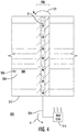
Fig. 3 is partial cross section view of the inductor ofFig. 1 , showing insulators arranged within the gap and heat being communicated through a spacer arranged in the gap to a heat sink according to an exemplary embodiment having a monolithic core construction; -
Fig. 4 is partial cross section view of the inductor ofFig. 1 , showing insulators arranged within the gap and heat being communicated through a spacer arranged in the gap to a heat sink according to an another exemplary embodiment having a layers core construction; -
Fig. 5 is a block diagram of a power conversion method using a flyback transformer or a transformer rectifier unit having the inductor ofFig. 1 , showing steps of the method. - Reference will now be made to the drawings wherein like reference numerals identify similar structural features or aspects of the subject disclosure. For purposes of explanation and illustration, and not limitation, a partial view of an exemplary embodiment of a magnetic core with a spacer formed from a semi-conductive material in accordance with the disclosure is shown in
Fig. 1 and is designated generally byreference character 100. Other embodiments of magnetic cores, transformer rectifier units having ferromagnetic cores with segments spaced by semi-conductive materials, and power conversion methods in accordance with the disclosure, or aspects thereof, are provided inFigs. 2-5 , as will be described. The systems and methods described herein can be used in magnetic cores for inductors, such as in flyback transformers or transformer rectifier units for aircraft electrical systems, though the present disclosure is not limited to aircraft electrical systems or a particular type of electrical device in general. - Referring to
Fig. 1 , aninductor 102 is shown.Inductor 102 includesmagnetic core 100.Magnetic core 100 includes afirst core segment 104, asecond core segment 106, and aspacer 108.Second core segment 106 is spaced apart fromfirst core segment 104 by agap 110 andspacer 108 is arranged withgap 110.Spacer 108 includes a semi-conductive material 112 (shown inFig. 2 ) to limit arc radius 113 of magnetic flux lines M (shown inFig. 2 ) communicated betweenfirst core segment 104 andsecond core segment 106 radially outward ofgap 110. - A winding 114 is wrapped about at least a portion of
magnetic core 100. Winding 114 carries a current i, which induces magnetic flux M (shown inFig. 2 ). In certain embodiments winding 114 is part of flyback transformer 10. In accordance with certain embodiments winding 114 can be part of a transformer rectifier unit (TRU) 12, such as for an aircraft electrical system. In the illustrated exemplary embodimentmagnetic core 100 has atoroid shape 116.Toroid shape 116 is defined by eight (8) core segments sequentially spaced apart from one another by eight (8) spacers. This is for illustration purposes only and is non-limiting. As will be appreciated by those of skill in the art in view of the present disclosure,magnetic core 100 can have fewer than eight segments or more than eight segments, as suitable for an intended application. As will also be appreciated by those of skill in the art in view of the present disclosure,magnetic core 100 can have another shape, such as a U-shape or an E-shape, and remain within the scope of the present disclosure. - With reference to
Fig. 2 ,inductor 102 is shown.First core segment 104 andsecond core segment 106 each include a ferromagnetic material 105 (shown inFig. 2 ).Spacer 108 is arranged withingap 110 betweenfirst core segment 104 andsecond core segment 106.Inductor 102 also includes afirst insulator 118 and asecond insulator 120.First insulator 118 is arranged withingap 110 betweenfirst core segment 104 andspacer 108.Second insulator 120 is also arranged withingap 110, and is additionally located betweensecond core segment 106 andspacer 108. Winding 114 extends aboutfirst core segment 104,spacer 108, andsecond core segment 106. - It is contemplated that
first insulator 118 andsecond insulator 120 each be formed from aninsulator material 109 that is both a good electrical insulator,spacer 108 thereby being electrically isolated (i.e. electrically insulated) fromfirst core segment 104 andsecond core segment 106. In certainembodiments insulator material 109 is a dielectric adhesive material, which facilitates fabrication ofmagnetic core 100 as well as providing suitable electrical isolation. Further, in accordance with certain embodiments, it is also contemplated that the material formingfirst insulator 118 andsecond insulator 120 each be formed from a material with a relatively good heat transfer coefficient for removing heat fromsecond core segment 106, thereby limiting permeability variation due to heating as a consequence of magnetic flux M communicated radially outward frommagnetic core 100 upon return tosecond core segment 106. -
Spacer 108 includessemi-conductive material 112. In certain embodimentssemi-conductive material 112 has a relative permeability of about 1. Relative permeability of about 1 enablesspacer 108 to communicate sufficient flux therethrough that magnetic flux lines radiated radially outward from magnetic core 100 (illustrated schematically with a single magnetic flux 'mean' flux line 122) return to second core segment with an angle that is less than about 90 degrees. This reduces the return angle ofmagnetic flux lines 122, limiting so-called flux crowding in the exterior portion ofsecond core segment 106 boundingspacer 108, and limiting localized hearing at the portion. In certain embodimentssemi-conductive material 112 has an electrical resistivity that is greater than electrical resistivity of aluminum, which allowsgap 110 to have a relatively small gap width.Semi-conductive material 112 can be, for example, aluminum nitride. - It is contemplated that the arc radius of magnetic lines of flux entering the second core segment from the first core segment can be smaller than arc radius of magnetic flux entering the second core segment with an air spacer or aluminum spacer of substantially equivalent reluctance. In this respect, as shown in
Fig. 2 ,magnetic flux lines 122 have anarc radius 124 that is smaller than anarc radius 126 ofmagnetic flux lines 128 of an air gap spacer or a spacer used in themagnetic core 100 for purposes providing substantially the same reluctance atgap 110. While having arc radius greater than an ideal arc radius, e.g., a flat arc radius 130 (indicating no fringing flux in the vicinity of gap 110), it is contemplated that thatmagnetic flux lines 122 allow for positioning winding 114 atspacer 108 with equivalent radial separation as required atfirst core segment 104 andsecond core segment 106. This is becausesemi-conductive material 112 reduces magnitude ofmagnetic flux lines 122 such that eddy current formation on winding 114 is limited, and the associated cross talk relatively small. - Referring now to
Fig. 3 ,magnetic core 100 is shown according to an exemplary embodiment having amonolithic construction 140. As used herein the term monolithic means thatmagnetic core 100 does not include stacked layers and/or laminated sheets within its respective core segments. Instead, as shown inFig. 3 ,ferromagnetic material 105 included inmagnetic core 100 includes a material formed from ferrite orpowdered metal 132. As will be appreciated by those of skill in the art in view of the present disclosure, use of powdered metal eliminates the intra-segment barrier that sheet interfaces can pose to magnetic flux communication, and the associated efficiency losses due to heating at such interfaces. This is because of the homogeneity provided by the monolithic construction ofmagnetic core 100 when constructed using ferrite orpowdered metal 132. - As also shown in
Fig. 3 ,magnetic core 100 is thermally grounded. In thisrespect inductor 102 includes athermal ground 134 connectingsecond core segment 106 to aheat sink 136 throughspacer 108 andsecond insulator 120. More particularly,thermal ground 134 is connected (i.e., thermally and electrically) directly tospacer 108. This allows heat H generated at the radially outer periphery ofsecond core segment 106 to be communicated bysecond insulator 120 tospacer 108, and therethrough toheat sink 136 throughthermal ground 134. Communicating heat H toheat sink 136 prevents H from locally changing permeability ofmagnetic core 100, which could otherwise offset at least in part the permeability homogeneity provided by ferrite orpowdered metal 132. This is particularly the case at relative high current flow levels.Heat sink 136 can be, for example, a chassis of an electrical device, such as flyback transformer 10 (shown inFig. 1 ) or TRU 12 (shown inFig. 1 ) by way of example. In certain embodiments flyback transformer or TRU 10 is configured and adapted to convert 120 voltage alternating current power into 28 volt direct current power. However, as will be appreciated by those of skill in the art in view to the present disclosure, flyback transformers and TRU device with higher or lower ratings, as well as other electrical devices, can also benefit from the present disclosure due to the reduced weight ofmagnetic core 100 and lower operating temperature ofinductor 102 associated withmagnetic core 100. - Referring now to
Fig. 4 ,magnetic core 200 is shown according to another exemplary embodiment having a layeredconstruction 202. As used herein the term layered means thatmagnetic core 200 includes wound, stacked, layered and/or laminated sheets within its respective core segments. More particularly, the ferromagnetic material 105 (shown inFig. 2 ) included inmagnetic core 100 is formed from a plurality ofsheets 204.Sheets 204 can be formed from anelectric steel material 206, which is amendable to stamping and laminating to form relative complex core shapes (e.g., non-toroid shaped). As will be appreciated by those of skill in the art in view of the present disclosure, uselayered construction 202 can reduce the cost of fabricatingmagnetic core 200. As will also be appreciated by those of skill in the art in view of the present disclosure,layered construction 202 can be more sensitive to the return angle ofmagnetic flux lines 122 due to the interface proximate (i.e., under) the location wheremagnetic flux lines 122 return tosecond core segment 106 where the outer sheet is joined to the inner sheets.Layered construction 202 thereby aggravates the tendency of heat H to be generated at the return location. - To limit the magnitude of heat H associated with the return of
magnetic flux lines 122 to the locationadjacent gap 208,magnetic core 200 is also thermally grounded. In this respectmagnetic core 200 withlayered construction 202 also includes athermal ground 210 connectingsecond core segment 212 to aheat sink 214 through spacer 216 and second insulator 218. Connectivity toheat sink 214 allows for communication of heat H toheat sink 214, preventing heat H from locally changing permeability ofmagnetic core 200 and potentially extending the use oflayered construction 202 to applications where current flow i (shown inFig. 1 ) could otherwise preclude the use oflayered construction 202. - With reference to
Fig. 5 , apower conversion method 300 is shown.Power conversion method 300 includes, at an inductor having a magnetic core, e.g., magnetic core 100 (shown inFig. 1 ) or magnetic core 200 (shown inFig. 4 ), inducing magnetic flux, e.g., magnetic flux M (shown inFig. 2 ), as shown withbox 310. The magnetic flux is communicated from the first core segment, e.g., first core segment 104 (shown inFig. 1 ), to the second core segment 106 (shown inFig. 1 ), shown withbox 320. The arc radius of the magnetic flux lines is limited by the material forming the spacer located between the first core segment and the second core segment, e.g., semi-conductive material 112 (shown inFig. 2 ), as shown withbox 330. - It is contemplated that the magnetic flux lines have an arc radius smaller than that of an air gap having similar reluctance, as shown with
box 332. It is also contemplated that the magnetic flux lines have an arc radius that is less than 90 degrees, as shown withbox 334. In this respect the radius of lines of magnetic flux returning to the second core segment from the first segment can be less than an air spacer or aluminum spacer of substantially equivalent reluctance. Further, in certain embodiments, the spacer can be electrically separated from the second core segment with an insulator, as shown withbox 340. Heat can be transferred from the location where the lines of magnetic flux return to the core through a heat sink thermally coupled to the second core segment by the spacer, as shown withbox 350. - Gap losses related to large fringing flux in cut toroidal inductors can cause excessive heating. The magnetic field radiated outward can also cause additional losses in the housing containing the inductor. This magnetic field is radiated radially outward due to the reluctance of air or similar gap material. One approach to limit the impact of fringing flux is to increase the number of gaps and make each gap relatively small in width, thereby reducing the reluctance at each gap. While generally acceptable for its intended purpose, small gaps tend to cause the fringing flux to re-enter the core material at an angle perpendicular to the core due to the gap width, resulting in heating. Another approach is to construct the spacer from a low reluctance material, such as aluminum. While generally acceptable, aluminum tends to develop eddy currents in the spacer, which limits the effectiveness of the spacer as energy level increases.
- In embodiments described herein a semi-conductive material is inserted into the gaps of the inductor. The semi-conductive material reduces the reluctance of the gap and directs the lines of flux associated with the fringing flux. In accordance with certain embodiments, the spacer material can have a reluctance substantially equivalent to the material forming the core, thereby limiting the arc radius of the fringing flux and causing a relatively large proportion of th magnetic flux to be communicated through the spacer rather than radially outward of the spacer. It is also contemplated that the spacer can be used to thermally shunt heat generated by the returning flux to a heat sink. This can result in both a weight reduction and lower operating temperature of the inductor owing to the use of the semi-conductive material forming the spacer.
- The methods and systems of the present disclosure, as described above and shown in the drawings, provide for gapped core bodies with superior properties including small arc radius of magnetic flux lines radiated outward of the core proximate the gap between core segments of a segmented core. While the apparatus and methods of the subject disclosure have been shown and described with reference to preferred embodiments, those skilled in the art will readily appreciate that changes and/or modifications may be made thereto without departing from the scope of the subject disclosure.
Claims (15)
- A magnetic core (100) for an inductor, comprising:a first core segment (104);a second core segment (106) spaced apart from the first core segment (104) by a gap (110); anda spacer (108) arranged within the gap (110) and between the first and second core segments (104, 106), wherein the spacer (108) includes a semi-conductive material (112) to limit arc radius of magnetic flux lines communicated outside of the gap (110) and between the first core segment (104) and the second core segment (106).
- The magnetic core as recited in claim 1, wherein the magnetic core (100) has a toroid shape.
- The magnetic core as recited in claims 1 or 2, wherein at least one of the first core segment (104) and the second core segment (106) include a ferromagnetic material.
- The magnetic core as recited in any preceding claim, wherein the core (100) has a monolithic construction; or
wherein the core (100) has a layered construction. - The magnetic core as recited in any preceding claim, wherein the semi-conductive material (112) includes aluminum nitride.
- The magnetic core as recited in any preceding claim, wherein the spacer (108) is electrically isolated from the first core segment (104), wherein the spacer (108) is electrically isolated from the second core segment (106).
- The magnetic core as recited in any preceding claim, further comprising an insulator arranged between the spacer (108) and the first core segment (104); and preferably wherein the insulator is a first insulator (118) and further comprising a second insulator (120), wherein the second insulator (120) is arranged between the spacer (108) and the second core segment (106).
- The magnetic core as recited in any preceding claim, further comprising a thermal ground (134) connection coupling the second core segment (106) to a heat sink (136) through the spacer (108) to limit heating of the second core segment (106) at a location where magnetic flux exiting the magnetic core (100) from first core segment (104) returns to the second core segment (106).
- The magnetic core as recited in any preceding claim, further comprising a winding (114) extending about the first core segment (104), the spacer (108), and the second core segment (106), and preferably
wherein separation between the winding (114) and the spacer (108) is substantially equivalent to spacing between the winding (114) and at least one of the first core segment (104) and the second core segment (106). - An inductor (102) including the magnetic core (100) as recited in claim 1, further comprising:a first insulator (118) arranged between the spacer (108) and the first core segment (104);a second insulator (120) arranged between the spacer (108) and the second core segment (106);a thermal ground (134) connecting the second core segment (106) to a heat sink (136) through the spacer (108) and the second insulator (120).
- The inductor as recited in claim 10, wherein arc radius of magnetic lines of flux entering the second core segment (106) from the first core segment (104) are smaller than arc radius of magnetic flux entering the second core segment (106) with an air spacer or aluminum spacer of substantially equivalent reluctance.
- A flyback transformer or transformer rectifier unit (TRU) including an inductor (102) as recited in claim 10.
- The flyback or TRU as recited in claim 12, wherein the flyback transformer or TRU is configured and adapted to convert 120 voltage alternating current power into 28 volt direct current power.
- A power conversion method, comprising:at a magnetic core with a winding wrapped thereabout and a first core segment, a second core segment spaced apart from the first core segment by a gap, and a spacer including a semi-conductive material arranged in the gap and between the first and second core segments;inducing magnetic flux in the first core segment;communicating the magnetic flux to the second core segment; andlimiting arc radius of magnetic flux lines returning to the second core segment with the semi-conductive material forming the spacer.
- The method as recited in claim 14, wherein arc radius of lines of magnetic flux returning to the second core segment from the first segment is less than an air spacer or aluminum spacer of substantially equivalent reluctance; and/or
further comprising electrically separating the spacer from the second core segment with an insulator; and/or
further comprising transferring heat from the location where the lines of magnetic flux return to second core segment through a heat sink thermally coupled to the second core segment by the spacer.
Applications Claiming Priority (1)
| Application Number | Priority Date | Filing Date | Title |
|---|---|---|---|
| US16/111,089 US10840004B2 (en) | 2018-08-23 | 2018-08-23 | Reducing reluctance in magnetic devices |
Publications (1)
| Publication Number | Publication Date |
|---|---|
| EP3614404A1 true EP3614404A1 (en) | 2020-02-26 |
Family
ID=67659677
Family Applications (1)
| Application Number | Title | Priority Date | Filing Date |
|---|---|---|---|
| EP19192825.8A Withdrawn EP3614404A1 (en) | 2018-08-23 | 2019-08-21 | Reducing reluctance in magnetic devices |
Country Status (2)
| Country | Link |
|---|---|
| US (1) | US10840004B2 (en) |
| EP (1) | EP3614404A1 (en) |
Families Citing this family (1)
| Publication number | Priority date | Publication date | Assignee | Title |
|---|---|---|---|---|
| EP4699150A2 (en) * | 2023-04-17 | 2026-02-25 | Massachusetts Institute Of Technology | High-frequency high-efficiency self-shielded inductor |
Citations (8)
| Publication number | Priority date | Publication date | Assignee | Title |
|---|---|---|---|---|
| US4978906A (en) * | 1989-03-29 | 1990-12-18 | Fmtt, Inc. | Picture frame matrix transformer |
| US20070080769A1 (en) * | 2005-10-11 | 2007-04-12 | Hamilton Sundstrand Corporation | High current, multiple air gap, conduction cooled, stacked lamination inductor |
| US20070090916A1 (en) * | 2005-10-21 | 2007-04-26 | Rao Dantam K | Quad-gapped toroidal inductor |
| US20090146769A1 (en) * | 2007-12-06 | 2009-06-11 | Hamilton Sundstrand Corporation | Light-weight, conduction-cooled inductor |
| WO2014091589A1 (en) * | 2012-12-12 | 2014-06-19 | 新電元工業株式会社 | Magnetic device, magnetic-bias-applying member, and method for manufacturing magnetic-bias-applying member |
| US20140218012A1 (en) * | 2013-02-01 | 2014-08-07 | Denso Corporation | Detector of magnetic bias, magnetic saturation, or amount of magnetic flux |
| US20160301315A1 (en) * | 2013-11-27 | 2016-10-13 | Hep Tech Co., Ltd | Flyback ac-dc conversion device and conversion method thereof |
| WO2017208745A1 (en) * | 2016-05-30 | 2017-12-07 | 三菱電機株式会社 | Circuit device and power conversion device |
Family Cites Families (7)
| Publication number | Priority date | Publication date | Assignee | Title |
|---|---|---|---|---|
| JPH0694864B2 (en) | 1984-07-26 | 1994-11-24 | 日本電装株式会社 | Ignition device for internal combustion engine |
| US5065073A (en) * | 1988-11-15 | 1991-11-12 | Frus John R | Apparatus and method for providing ignition to a turbine engine |
| US5692483A (en) | 1995-06-30 | 1997-12-02 | Nippondenso Co., Ltd. | Ignition coil used for an internal combustion engine |
| US6512438B1 (en) * | 1999-12-16 | 2003-01-28 | Honeywell International Inc. | Inductor core-coil assembly and manufacturing thereof |
| JP2004507099A (en) * | 2000-08-24 | 2004-03-04 | コーニンクレッカ フィリップス エレクトロニクス エヌ ヴィ | Method for manufacturing core having substantially closed loop, core and magnetic coil |
| US6992555B2 (en) | 2003-01-30 | 2006-01-31 | Metglas, Inc. | Gapped amorphous metal-based magnetic core |
| US20090079532A1 (en) | 2007-09-20 | 2009-03-26 | Muelleman Norman F | Composite Magnetic Core Construction |
-
2018
- 2018-08-23 US US16/111,089 patent/US10840004B2/en active Active
-
2019
- 2019-08-21 EP EP19192825.8A patent/EP3614404A1/en not_active Withdrawn
Patent Citations (8)
| Publication number | Priority date | Publication date | Assignee | Title |
|---|---|---|---|---|
| US4978906A (en) * | 1989-03-29 | 1990-12-18 | Fmtt, Inc. | Picture frame matrix transformer |
| US20070080769A1 (en) * | 2005-10-11 | 2007-04-12 | Hamilton Sundstrand Corporation | High current, multiple air gap, conduction cooled, stacked lamination inductor |
| US20070090916A1 (en) * | 2005-10-21 | 2007-04-26 | Rao Dantam K | Quad-gapped toroidal inductor |
| US20090146769A1 (en) * | 2007-12-06 | 2009-06-11 | Hamilton Sundstrand Corporation | Light-weight, conduction-cooled inductor |
| WO2014091589A1 (en) * | 2012-12-12 | 2014-06-19 | 新電元工業株式会社 | Magnetic device, magnetic-bias-applying member, and method for manufacturing magnetic-bias-applying member |
| US20140218012A1 (en) * | 2013-02-01 | 2014-08-07 | Denso Corporation | Detector of magnetic bias, magnetic saturation, or amount of magnetic flux |
| US20160301315A1 (en) * | 2013-11-27 | 2016-10-13 | Hep Tech Co., Ltd | Flyback ac-dc conversion device and conversion method thereof |
| WO2017208745A1 (en) * | 2016-05-30 | 2017-12-07 | 三菱電機株式会社 | Circuit device and power conversion device |
Non-Patent Citations (3)
| Title |
|---|
| ANONYMOUS: "Magnetic core - Wikipedia", WIKIPEDIA, 5 June 2017 (2017-06-05), pages 1 - 8, XP055514410, Retrieved from the Internet <URL:https://en.wikipedia.org/w/index.php?title=Magnetic_core&oldid=783992097#Sendust,_KoolMU> [retrieved on 20181011] * |
| WANG YIREN ET AL: "Thermal management of compact nanocrystalline inductors for power dense converters", 2018 IEEE APPLIED POWER ELECTRONICS CONFERENCE AND EXPOSITION (APEC), IEEE, 4 March 2018 (2018-03-04), pages 2696 - 2703, XP033347618, DOI: 10.1109/APEC.2018.8341398 * |
| YUJI NAGAI ET AL: "Thermal Conductivity of Epoxy Resin Filled with Particulate Aluminum Nitride Powder", JOURNAL OF THE CERAMIC SOCIETY OF JAPAN, vol. 105, no. 1219, 1997, JP, pages 197 - 200, XP055638874, ISSN: 0914-5400, DOI: 10.2109/jcersj.105.197 * |
Also Published As
| Publication number | Publication date |
|---|---|
| US20200066434A1 (en) | 2020-02-27 |
| US10840004B2 (en) | 2020-11-17 |
Similar Documents
| Publication | Publication Date | Title |
|---|---|---|
| US6806803B2 (en) | Transformer winding | |
| US20150109090A1 (en) | Electrical transformer with a shielded cast coil assembly | |
| WO2012157053A1 (en) | Reactor device and power converter employing same | |
| CN104835629B (en) | The adjustable high voltage transformer unit of leakage field and its application and converter circuit | |
| EP2787515B1 (en) | Inductor gap spacer | |
| US20150109081A1 (en) | Cast coil assembly with fins for an electrical transformer | |
| US20180218826A1 (en) | Magnetic core, and choke or transformer having such a magnetic core | |
| US9123461B2 (en) | Reconfiguring tape wound cores for inductors | |
| CN104205259B (en) | Transformers for Electric Vehicles | |
| US10840004B2 (en) | Reducing reluctance in magnetic devices | |
| EP2187408B1 (en) | Iron core reactor | |
| EP3062319B1 (en) | Transformer for reducing eddy current losses of coil | |
| JP5399317B2 (en) | Reactor | |
| CN1842436B (en) | Magnetic device for loading guiding and/or braking system in magnetic levitation train | |
| WO1993000692A1 (en) | Segmented core inductor | |
| KR101595774B1 (en) | Composite Coil Module for Transmitting Wireless Power | |
| US10147539B2 (en) | Magnetic core of rotating transformer | |
| KR101506698B1 (en) | iron core winding assembly for transformer | |
| US20170092419A1 (en) | Magnetically permeable core and an inductive power transfer coil arrangement | |
| EP3425645A1 (en) | Transformers with integrated inductors | |
| EP2682959A2 (en) | Magnetic structures for large air gap | |
| KR20220063200A (en) | Planar transformer with reduced parasitic losses | |
| KR102135202B1 (en) | Transformer | |
| KR101193408B1 (en) | A transformer for an inverter | |
| EP3349225B1 (en) | Core for an electric shunt reactor |
Legal Events
| Date | Code | Title | Description |
|---|---|---|---|
| PUAI | Public reference made under article 153(3) epc to a published international application that has entered the european phase |
Free format text: ORIGINAL CODE: 0009012 |
|
| STAA | Information on the status of an ep patent application or granted ep patent |
Free format text: STATUS: THE APPLICATION HAS BEEN PUBLISHED |
|
| AK | Designated contracting states |
Kind code of ref document: A1 Designated state(s): AL AT BE BG CH CY CZ DE DK EE ES FI FR GB GR HR HU IE IS IT LI LT LU LV MC MK MT NL NO PL PT RO RS SE SI SK SM TR |
|
| AX | Request for extension of the european patent |
Extension state: BA ME |
|
| STAA | Information on the status of an ep patent application or granted ep patent |
Free format text: STATUS: REQUEST FOR EXAMINATION WAS MADE |
|
| 17P | Request for examination filed |
Effective date: 20200821 |
|
| RBV | Designated contracting states (corrected) |
Designated state(s): AL AT BE BG CH CY CZ DE DK EE ES FI FR GB GR HR HU IE IS IT LI LT LU LV MC MK MT NL NO PL PT RO RS SE SI SK SM TR |
|
| STAA | Information on the status of an ep patent application or granted ep patent |
Free format text: STATUS: EXAMINATION IS IN PROGRESS |
|
| 17Q | First examination report despatched |
Effective date: 20210114 |
|
| STAA | Information on the status of an ep patent application or granted ep patent |
Free format text: STATUS: THE APPLICATION HAS BEEN WITHDRAWN |
|
| 18W | Application withdrawn |
Effective date: 20221219 |