EP3614373A2 - Multi-degree of freedom acoustic panel - Google Patents
Multi-degree of freedom acoustic panel Download PDFInfo
- Publication number
- EP3614373A2 EP3614373A2 EP19192920.7A EP19192920A EP3614373A2 EP 3614373 A2 EP3614373 A2 EP 3614373A2 EP 19192920 A EP19192920 A EP 19192920A EP 3614373 A2 EP3614373 A2 EP 3614373A2
- Authority
- EP
- European Patent Office
- Prior art keywords
- skin
- ply
- cavities
- sidewall
- septums
- Prior art date
- Legal status (The legal status is an assumption and is not a legal conclusion. Google has not performed a legal analysis and makes no representation as to the accuracy of the status listed.)
- Granted
Links
Images







Classifications
-
- G—PHYSICS
- G10—MUSICAL INSTRUMENTS; ACOUSTICS
- G10K—SOUND-PRODUCING DEVICES; METHODS OR DEVICES FOR PROTECTING AGAINST, OR FOR DAMPING, NOISE OR OTHER ACOUSTIC WAVES IN GENERAL; ACOUSTICS NOT OTHERWISE PROVIDED FOR
- G10K11/00—Methods or devices for transmitting, conducting or directing sound in general; Methods or devices for protecting against, or for damping, noise or other acoustic waves in general
- G10K11/16—Methods or devices for protecting against, or for damping, noise or other acoustic waves in general
- G10K11/172—Methods or devices for protecting against, or for damping, noise or other acoustic waves in general using resonance effects
-
- F—MECHANICAL ENGINEERING; LIGHTING; HEATING; WEAPONS; BLASTING
- F02—COMBUSTION ENGINES; HOT-GAS OR COMBUSTION-PRODUCT ENGINE PLANTS
- F02K—JET-PROPULSION PLANTS
- F02K1/00—Plants characterised by the form or arrangement of the jet pipe or nozzle; Jet pipes or nozzles peculiar thereto
- F02K1/78—Other construction of jet pipes
- F02K1/82—Jet pipe walls, e.g. liners
- F02K1/827—Sound absorbing structures or liners
-
- B—PERFORMING OPERATIONS; TRANSPORTING
- B32—LAYERED PRODUCTS
- B32B—LAYERED PRODUCTS, i.e. PRODUCTS BUILT-UP OF STRATA OF FLAT OR NON-FLAT, e.g. CELLULAR OR HONEYCOMB, FORM
- B32B3/00—Layered products comprising a layer with external or internal discontinuities or unevennesses, or a layer of non-planar shape; Layered products comprising a layer having particular features of form
- B32B3/10—Layered products comprising a layer with external or internal discontinuities or unevennesses, or a layer of non-planar shape; Layered products comprising a layer having particular features of form characterised by a discontinuous layer, i.e. formed of separate pieces of material
- B32B3/12—Layered products comprising a layer with external or internal discontinuities or unevennesses, or a layer of non-planar shape; Layered products comprising a layer having particular features of form characterised by a discontinuous layer, i.e. formed of separate pieces of material characterised by a layer of regularly- arranged cells, e.g. a honeycomb structure
-
- B—PERFORMING OPERATIONS; TRANSPORTING
- B32—LAYERED PRODUCTS
- B32B—LAYERED PRODUCTS, i.e. PRODUCTS BUILT-UP OF STRATA OF FLAT OR NON-FLAT, e.g. CELLULAR OR HONEYCOMB, FORM
- B32B3/00—Layered products comprising a layer with external or internal discontinuities or unevennesses, or a layer of non-planar shape; Layered products comprising a layer having particular features of form
- B32B3/26—Layered products comprising a layer with external or internal discontinuities or unevennesses, or a layer of non-planar shape; Layered products comprising a layer having particular features of form characterised by a particular shape of the outline of the cross-section of a continuous layer; characterised by a layer with cavities or internal voids ; characterised by an apertured layer
- B32B3/266—Layered products comprising a layer with external or internal discontinuities or unevennesses, or a layer of non-planar shape; Layered products comprising a layer having particular features of form characterised by a particular shape of the outline of the cross-section of a continuous layer; characterised by a layer with cavities or internal voids ; characterised by an apertured layer characterised by an apertured layer, the apertures going through the whole thickness of the layer, e.g. expanded metal, perforated layer, slit layer regular cells B32B3/12
-
- F—MECHANICAL ENGINEERING; LIGHTING; HEATING; WEAPONS; BLASTING
- F02—COMBUSTION ENGINES; HOT-GAS OR COMBUSTION-PRODUCT ENGINE PLANTS
- F02C—GAS-TURBINE PLANTS; AIR INTAKES FOR JET-PROPULSION PLANTS; CONTROLLING FUEL SUPPLY IN AIR-BREATHING JET-PROPULSION PLANTS
- F02C7/00—Features, components parts, details or accessories, not provided for in, or of interest apart form groups F02C1/00 - F02C6/00; Air intakes for jet-propulsion plants
- F02C7/24—Heat or noise insulation
-
- G—PHYSICS
- G10—MUSICAL INSTRUMENTS; ACOUSTICS
- G10K—SOUND-PRODUCING DEVICES; METHODS OR DEVICES FOR PROTECTING AGAINST, OR FOR DAMPING, NOISE OR OTHER ACOUSTIC WAVES IN GENERAL; ACOUSTICS NOT OTHERWISE PROVIDED FOR
- G10K11/00—Methods or devices for transmitting, conducting or directing sound in general; Methods or devices for protecting against, or for damping, noise or other acoustic waves in general
- G10K11/16—Methods or devices for protecting against, or for damping, noise or other acoustic waves in general
- G10K11/162—Selection of materials
- G10K11/168—Plural layers of different materials, e.g. sandwiches
-
- B—PERFORMING OPERATIONS; TRANSPORTING
- B32—LAYERED PRODUCTS
- B32B—LAYERED PRODUCTS, i.e. PRODUCTS BUILT-UP OF STRATA OF FLAT OR NON-FLAT, e.g. CELLULAR OR HONEYCOMB, FORM
- B32B2307/00—Properties of the layers or laminate
- B32B2307/10—Properties of the layers or laminate having particular acoustical properties
-
- B—PERFORMING OPERATIONS; TRANSPORTING
- B32—LAYERED PRODUCTS
- B32B—LAYERED PRODUCTS, i.e. PRODUCTS BUILT-UP OF STRATA OF FLAT OR NON-FLAT, e.g. CELLULAR OR HONEYCOMB, FORM
- B32B2605/00—Vehicles
- B32B2605/18—Aircraft
-
- B—PERFORMING OPERATIONS; TRANSPORTING
- B64—AIRCRAFT; AVIATION; COSMONAUTICS
- B64D—EQUIPMENT FOR FITTING IN OR TO AIRCRAFT; FLIGHT SUITS; PARACHUTES; ARRANGEMENT OR MOUNTING OF POWER PLANTS OR PROPULSION TRANSMISSIONS IN AIRCRAFT
- B64D33/00—Arrangement in aircraft of power plant parts or auxiliaries not otherwise provided for
- B64D33/02—Arrangement in aircraft of power plant parts or auxiliaries not otherwise provided for of combustion air intakes
- B64D2033/0206—Arrangement in aircraft of power plant parts or auxiliaries not otherwise provided for of combustion air intakes comprising noise reduction means, e.g. acoustic liners
-
- B—PERFORMING OPERATIONS; TRANSPORTING
- B64—AIRCRAFT; AVIATION; COSMONAUTICS
- B64D—EQUIPMENT FOR FITTING IN OR TO AIRCRAFT; FLIGHT SUITS; PARACHUTES; ARRANGEMENT OR MOUNTING OF POWER PLANTS OR PROPULSION TRANSMISSIONS IN AIRCRAFT
- B64D29/00—Power-plant nacelles, fairings or cowlings
-
- F—MECHANICAL ENGINEERING; LIGHTING; HEATING; WEAPONS; BLASTING
- F02—COMBUSTION ENGINES; HOT-GAS OR COMBUSTION-PRODUCT ENGINE PLANTS
- F02C—GAS-TURBINE PLANTS; AIR INTAKES FOR JET-PROPULSION PLANTS; CONTROLLING FUEL SUPPLY IN AIR-BREATHING JET-PROPULSION PLANTS
- F02C7/00—Features, components parts, details or accessories, not provided for in, or of interest apart form groups F02C1/00 - F02C6/00; Air intakes for jet-propulsion plants
- F02C7/04—Air intakes for gas-turbine plants or jet-propulsion plants
- F02C7/045—Air intakes for gas-turbine plants or jet-propulsion plants having provisions for noise suppression
-
- F—MECHANICAL ENGINEERING; LIGHTING; HEATING; WEAPONS; BLASTING
- F05—INDEXING SCHEMES RELATING TO ENGINES OR PUMPS IN VARIOUS SUBCLASSES OF CLASSES F01-F04
- F05B—INDEXING SCHEME RELATING TO WIND, SPRING, WEIGHT, INERTIA OR LIKE MOTORS, TO MACHINES OR ENGINES FOR LIQUIDS COVERED BY SUBCLASSES F03B, F03D AND F03G
- F05B2250/00—Geometry
- F05B2250/20—Geometry three-dimensional
- F05B2250/28—Geometry three-dimensional patterned
- F05B2250/283—Honeycomb
-
- F—MECHANICAL ENGINEERING; LIGHTING; HEATING; WEAPONS; BLASTING
- F05—INDEXING SCHEMES RELATING TO ENGINES OR PUMPS IN VARIOUS SUBCLASSES OF CLASSES F01-F04
- F05D—INDEXING SCHEME FOR ASPECTS RELATING TO NON-POSITIVE-DISPLACEMENT MACHINES OR ENGINES, GAS-TURBINES OR JET-PROPULSION PLANTS
- F05D2260/00—Function
- F05D2260/96—Preventing, counteracting or reducing vibration or noise
-
- Y—GENERAL TAGGING OF NEW TECHNOLOGICAL DEVELOPMENTS; GENERAL TAGGING OF CROSS-SECTIONAL TECHNOLOGIES SPANNING OVER SEVERAL SECTIONS OF THE IPC; TECHNICAL SUBJECTS COVERED BY FORMER USPC CROSS-REFERENCE ART COLLECTIONS [XRACs] AND DIGESTS
- Y02—TECHNOLOGIES OR APPLICATIONS FOR MITIGATION OR ADAPTATION AGAINST CLIMATE CHANGE
- Y02T—CLIMATE CHANGE MITIGATION TECHNOLOGIES RELATED TO TRANSPORTATION
- Y02T50/00—Aeronautics or air transport
- Y02T50/60—Efficient propulsion technologies, e.g. for aircraft
Definitions
- This disclosure relates generally to acoustic panels and, more particularly, to multi-degree of freedom acoustic panels and methods for forming such panels.
- a nacelle of a typical aircraft propulsion system includes one or more acoustic panels to attenuate propulsion system related noise.
- One type of such acoustic panels is a double degree of freedom (DDoF) acoustic panel.
- a typical DDoF acoustic panel includes a honeycomb core disposed between and bonded to a perforated outer skin and a non-perforated inner skin.
- a septum is disposed within each hexagonal cavity of the honeycomb core to divide that cavity into a pair of fluidly coupled sub-cavities, thereby forming a double-degree of freedom acoustic resonance chamber.
- each septum is formed from a discrete piece of material (e.g., a plug) which is individually placed into a respective cavity and then attached to cavity sidewalls.
- a discrete piece of material e.g., a plug
- Such an individual septum arrangement process can be time consuming and expensive.
- an acoustic panel includes a first skin, a second skin and a cellular core vertically between and connected to the first skin and the second skin.
- the cellular core includes a plurality of cavities, a plurality of sidewalls and a plurality of septums.
- Each of the plurality of cavities extends vertically through the cellular core between the first skin and the second skin.
- Each of the plurality of cavities extends laterally within the cellular core between a respective laterally adjacent pair of the plurality of sidewalls.
- Each of the plurality of septums vertically divides a respective one of the plurality of cavities into a set of fluidly coupled sub-cavities.
- a set of the plurality of septums is formed by a ply of folded material.
- Each of the set of the plurality of septums have a four-sided polygonal shape when viewed in a plane that is parallel to the first skin.
- another acoustic panel includes a first skin, a second skin and a cellular core vertically between and connected to the first skin and the second skin.
- the cellular core includes a plurality of cavities, a plurality of sidewalls and a plurality of septums.
- Each of the plurality of cavities extends vertically through the cellular core between the first skin and the second skin.
- Each of the plurality of cavities extends laterally within the cellular core between a respective laterally adjacent pair of the plurality of sidewalls.
- Each of the plurality of septums vertically divides a respective one of the plurality of cavities into a set of fluidly coupled sub-cavities.
- the plurality of sidewalls include a first sidewall and a second sidewall.
- the plurality of cavities include a first cavity that extends laterally between the first sidewall and the second sidewall.
- the plurality of septums include a first septum within the first cavity.
- a ply of folded material forms at least the first septum and a portion of the first sidewall. The ply of folded material contacts the second skin at an interface between the first sidewall and the second skin, and is separated from the second skin at an interface between the second sidewall and the second skin.
- another acoustic panel includes a first skin, a second skin and a cellular core vertically between and connected to the first skin and the second skin.
- the cellular core includes a plurality of cavities, a plurality of sidewalls and a plurality of septums.
- Each of the plurality of cavities extends vertically through the cellular core between the first skin and the second skin.
- Each of the plurality of cavities extends laterally within the cellular core between a respective laterally adjacent pair of the plurality of sidewalls.
- Each of the plurality of septums vertically divides a respective one of the plurality of cavities into a set of fluidly coupled sub-cavities.
- a set of the plurality of septums is formed by a ply of folded material.
- the plurality of septums includes a first septum.
- the first septum includes a first portion of the ply of folded material and a second portion of the ply of folded material that lays against the first portion of the ply of folded material.
- the four-sided polygonal shape may be a square.
- the set of the plurality of septums may be arranged in a longitudinal extending array.
- the plurality of sidewalls may include a first sidewall and a second sidewall.
- the plurality of cavities may include a first cavity that extends laterally between the first sidewall and the second sidewall.
- the plurality of septums may include a first septum within the first cavity.
- the ply of folded material may form the first septum.
- the first sidewall may include a second ply of material.
- the second sidewall may include a third ply of material.
- the first sidewall may further include a first portion of the ply of folded material.
- the second sidewall may further include a second portion of the ply of folded material.
- the first portion may have a first vertical height.
- the second portion may have a second vertical height that is different from the first vertical height.
- the first portion may vertically contact the second skin.
- the second portion may not contact the second skin.
- the first portion may vertically contact the second skin.
- the ply of folded material may be configured from or otherwise include metal.
- the ply of folded material may be configured from or otherwise include polymer.
- the ply of folded material may be configured from or otherwise include fiber-reinforced composite.
- the ply of folded material may be configured from or otherwise include woven fiber mesh.
- the first skin may be a perforated first skin.
- a second set of the plurality of septums may be formed by a second ply of folded material.
- the second set of the plurality of septums may be laterally adjacent the set of the plurality of septums.
- the plurality of septums may include a first septum.
- the first septum may include a first portion of the ply of folded material and a second portion of the ply of folded material that overlaps and lays against the first portion of the ply of folded material.
- the ply of folded material may further form a portion of the second sidewall.
- the ply of folded material may further form a second of the plurality of septums that is longitudinally adjacent the first septum.
- the first septum may include a four-sided polygonal shape when viewed in a plane that is parallel to the first skin.
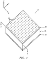
- FIG. 1 is a perspective illustration of a portion of a multi-degree of freedom acoustic panel 30; e.g., a double degree of freedom (DDoF) acoustic panel.
- This acoustic panel 30 is configured to attenuate sound (e.g., noise) generated, for example, by an aircraft propulsion system such as a turbofan propulsion system or a turbojet propulsion system.
- the acoustic panel 30 may be configured with a nacelle of the propulsion system.
- the acoustic panel 30, for example, may be configured as or with an inner or outer barrel, a translating sleeve of a thrust reverser, a blocker door, etc.
- the acoustic panel 30 may be configured with another component / structure of the aircraft such as its fuselage, a wing or a pylon for the propulsion system. Furthermore, the acoustic panel 30 may be configured to also or alternatively attenuate aircraft related sound other than that generated by the propulsion system.
- the acoustic panel 30 of the present disclosure may alternatively be configured for non-aircraft sound attenuation applications.
- the acoustic panel 30 of FIG. 1 extends longitudinally along a y-axis.
- the acoustic panel 30 extends laterally along an x-axis.
- the acoustic panel 30 extends vertically along a z-axis.
- the term "vertical" is used herein to describe a depthwise panel direction and is not limited to a gravitational up/down direction.
- the x-y plane is shown as a generally flat plane. However, in other embodiments, the x-y plane and, thus, the acoustic panel 30 may be curved and/or follow an undulating geometry.
- the x-y plane and, thus, the acoustic panel 30 may be arcuate, cylindrical or conical with or without radial undulations.
- the vertical direction may change at different locations along the x-y plane.
- the vertical direction may be a radial direction
- the longitudinal direction may be an axial (or circumferential) direction
- the lateral direction may be a circumferential (or axial) direction.
- the acoustic panel 30 includes a (e.g., acoustic) porous top skin 32 (e.g., a perforated face skin), a solid, non-perforated bottom skin 34 (e.g., a back skin) and a cellular core 36.
- a porous top skin 32 e.g., a perforated face skin
- a solid, non-perforated bottom skin 34 e.g., a back skin
- cellular core 36 e.g., cellular core
- the cellular core 36 is arranged and extends vertically between the top skin 32 and the bottom skin 34.
- the cellular core 36 is also connected to the top skin 32 and the bottom skin 34.
- the cellular core 36 may be welded, brazed, fused, adhered and/or otherwise bonded to or integral with the top skin 32 and/or the bottom skin 34 as discussed below in further detail.
- the top skin 32 of FIG. 1 is configured as a relatively thin sheet or layer of material that extends longitudinally and laterally along the x-y plane.
- This top skin material may include, but is not limited to, a metal (e.g., sheet metal or metal foil), a polymer (e.g., thermoplastic or thermoset material), a fiber reinforced composite (e.g., fiberglass composite, carbon fiber composite, aramid fiber composite, etc.), or a combination thereof.
- the top skin 32 may be formed from woven fiber mesh (e.g., polymer or fiber mesh). Referring now to FIG. 3 , the top skin 32 has a vertical thickness 38, which extends vertically between opposing first skin top and bottom side surfaces.
- the top skin 32 includes a plurality of passages 40; e.g., perforations such as through-holes. Each of these passages 40 extends generally vertically through the top skin 32 between its side surfaces. While the passages 40 are described above and illustrated in FIG. 3 as through-holes for ease of description, one or more of the passages 40 may also or alternatively be formed by one or more interconnected pores in the top skin material in alternative embodiments, for example, where the top skin is formed from woven fiber mesh.
- the bottom skin 34 of FIG. 1 is configured as a relatively thin sheet or layer of (e.g., solid, continuous, uninterrupted and/or fluidly impervious) material that extends longitudinally and laterally along the x-y plane.
- This bottom skin material may include, but is not limited to, a metal (e.g., sheet metal or metal foil), a polymer (e.g., thermoplastic or thermoset material), a fiber reinforced composite (e.g., fiberglass composite, carbon fiber composite, aramid fiber composite, etc.), or a combination thereof.
- the bottom skin material may be the same as or different than the top skin material.
- the bottom skin 34 has a vertical thickness 42, which extends vertically between opposing second skin top and bottom side surfaces. This vertical thickness 42 may be substantially equal to or different (e.g., greater or less) than the vertical thickness 38 of the top skin 32.
- the cellular core 36 extends longitudinally and laterally along the x-y plane.
- the cellular core 36 has a vertical thickness 44, which extends vertically between opposing core sides respectively abutted against the top skin 32 and the bottom skin 34.
- the vertical thickness 44 may be substantially greater than the vertical thickness 38, 42 of the top skin 32 and/or the bottom skin 34.
- the vertical thickness 44 of the core 36 may be at least ten to forty times (10-40x) or more greater than the vertical thickness 38, 42 of the skin 32, 34.
- the acoustic panel 30 of the present disclosure is not limited to such an exemplary embodiment.
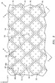
- the cellular core 36 of FIGS. 2-4 includes a plurality of sidewalls 46 (e.g., corrugated sidewalls), a plurality of cavities 48 and a plurality of porous septums 50.
- Each of the sidewalls 46 of FIG. 5 has a corrugated configuration. More particularly, each of the sidewalls 46 includes a plurality of corrugations 52 arranged in an end-to-end longitudinally extending array. Each corrugation 52 includes a first sidewall segment 54 and a second sidewall segment 56.
- a first (e.g., distal, exterior) end of the first sidewall segment 54 is connected (e.g., directly) to a first (e.g., distal, exterior) end of a second sidewall segment 56 of a longitudinally adjacent corrugation 52 in the array, thereby forming an inter-corrugation peak 58.
- a second (e.g., proximal, interior) end of the first sidewall segment 54 is connected (e.g., directly) to a second (e.g., proximal, interior) end of the second sidewall segment 56 of the same corrugation 52, thereby forming an intra-corrugation peak 60.
- the first sidewall segment 54 and the second sidewall segment 56 are angularly offset from one another (e.g., in the x-y plane) by an acute angle 62 such as, but not limited to, about (e.g., +/- 2°) or exactly ninety degrees ( ⁇ 90°).
- the first sidewall segment 54 has a first length 64.
- the second sidewall segment 56 has a second length 66 that may be substantially (e.g., +/- 2%) or exactly equal to the first length 64.
- the sidewalls 46A-C (generally referred to as "46") of FIG. 5 are arranged in a side-by-side laterally extending array so as to form the cavities 48 within the cellular core 36.
- the inter-corrugation peaks 58 of the sidewall 46A are (e.g., longitudinally) aligned with and are connected to the intra-corrugation peaks 60 of a respective laterally adjacent sidewall 46C.
- the intra-corrugation peaks 60 of the sidewall 46A are (e.g., longitudinally) aligned with and are connected to the inter-corrugation peaks 58 of another respective laterally adjacent sidewall 46B.
- each adjacent pair of the sidewalls 46 forms a set (e.g., a longitudinal extending array) of one or more of the cavities 48 within the cellular core 36.
- Each of the cavities 48 extends laterally between a respective laterally adjacent pair of the sidewalls 46.
- each of the cavities 48 extends laterally between the sidewall segments 54 and 56 of sidewalls 46A and 46B, respectively, and the sidewall segments 56 and 54 of sidewalls 46A and 46B, respectively.
- Each of the cavities 48 also extends longitudinally between the sidewall segments 54 and 56 of the respective sidewall 46A and the sidewall segments 54 and 56 of the respective sidewall 46B.
- Each of the cavities 48 may have a four-sided polygonal shape when viewed in a plane, which may be parallel to an x-y plane as well as the top and/or bottom skins 32 and 34 (see FIG. 1 ).
- the four-sided polygonal shape is a square.
- the four-sided polygonal shape may be a rectangle (see FIG. 6 ), a diamond (see FIG. 7 ) or otherwise.
- each of the cavities 48 extends vertically through the cellular core 36 between and to the top skin 32 and the bottom skin 34.
- each of the cavities 48 is fluidly coupled with one or more respective passages 40 in the top skin 32.
- each of the cavities 48 is fluidly discrete; e.g., not fluidly coupled with any other of the cavities 48 within the core 36.
- each of the sidewall segments 54, 56 is solid, continuous, uninterrupted and/or fluidly impervious. The present disclosure, however, is not limited to such embodiments.
- each of the septums 50 is located within a respective one of the cavities 48.
- Each of the septums 50 is configured to vertically divide the respective cavity 48 into a set (e.g., a pair) of fluidly coupled sub-cavities 48A and 48B.
- Each top sub-cavity 48A of FIGS. 3 and 4 extends vertically between and to the respective septum 50 and the top skin 32.
- Each bottom sub-cavity 48B of FIGS. 3 and 4 extends vertically between and to the respective septum 50 and the bottom skin 34.
- Each of the septums 50 includes one or more passages 68; e.g., perforations such as through-holes.
- Each of these passages 68 extends generally vertically through the respective septum 50.
- the passages 68 are operable to fluidly couple the top and bottom sub-cavities 48A and 48B together across the septum 50. While the passages 68 are described above and illustrated in FIGS. 3 and 4 as through-holes for ease of description, one or more of the passages 68 may also or alternatively be formed by one or more interconnected pores in the septum material in alternative embodiments.
- each of the septums 50 extends laterally between a respective laterally adjacent pair of the sidewalls 46. More particularly, each of the septums 50 extends laterally between the sidewall segments 54 and 56 of sidewalls 46A and 46B, respectively, and the sidewall segments 56 and 54 of sidewalls 46A and 46B, respectively. Each of the septums 50 also extends longitudinally between the sidewall segments 54 and 56 of the respective sidewall 46A and the sidewall segments 54 and 56 of the respective sidewall 46B.
- Each of the septums 50 may have a four-sided polygonal shape when viewed in a plane, which may be parallel to an x-y plane as well as the top and/or bottom skins 32 and 34 (see FIG. 1 ).
- the four-sided polygonal shape is a square.
- the four-sided polygonal shape may be a rectangle (see FIG. 6 ), a diamond (see FIG. 7 ) or otherwise.
- each septum 50 is vertically displaced from the top skin 32 by a non-zero first distance 70.
- Each septum is vertically displaced from the bottom skin 34 by a non-zero second distance 72.
- This second distance 72 may be the same and the first distance 70 as shown in FIG. 3 .
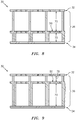
- the second distance 72 may be less than the first distance 70 as shown in FIG. 8 .
- the second distance 72 may be greater than the first distance 70 as shown in FIG. 9 .
- the first and the second distances 70 and 72 may be sized based on the frequencies of sounds the panel 30 is intended to attenuate.
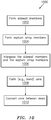
- FIG. 10 is a flow diagram of a method 1000 for forming an acoustic panel such as, but not limited to, the acoustic panel 30 of FIGS. 1-4 .
- step 1002 one or more sidewall members 74 are formed.
- An embodiment of an exemplary one of the sidewall members 74 is shown in FIG. 11 .
- a ply (e.g., a single sheet, strip or ribbon) of material 75 may be cut to size and is folded to generally have a configuration similar to the corrugated configuration of a respective one of the sidewalls 46; e.g., see FIG. 2 .
- one or more septum array members 76 is formed.
- a ply (e.g., a single sheet, strip or ribbon) of material 78 may be cut to size.
- one or more apertures 80 e.g., cutouts
- Each of the castellations 82 projects vertically out from a top edge of the base 84.
- Adjacent castellations 82 are longitudinally separated by a respective one of the apertures 80. Thus, the castellations 82 are interposed with the apertures 80.
- each of the castellations 82 is folded along a respective fold line 86 (see FIG. 13 ) such that, for example, the castellation 82 is angularly offset from the base 84 by an acute angle such as, but not limited to, about (e.g., +/- 2°) or exactly ninety degrees ( ⁇ 90°).
- the base 84 is folded back and forth (e.g., accordion folded) along fold lines 88 (see FIG. 13 ) to provide the base 84 with a corrugated configuration.
- each castellation 82 may then be attached (e.g., bonded) to a respective aperture edge 92 of the base 84.
- a plurality of apertures 94 may then be formed in the castellations 82, which apertures 94 will become the passages 68 of FIG. 2 .
- this perforation process may be performed earlier or later during this method 1000 in alternative embodiments.
- the septum array members 76 are interposed with the sidewall members 74.
- each septum array member 76 is located laterally between and abutted against an adjacent pair of the sidewall members 74.
- the cellular core 36 is formed.
- the members 74 and 76 are attached together via, for example, welding, brazing, adhering and/or otherwise bonding.
- one or both of the remaining free edges 96 and 98 of each castellation 82 are attached to a respective one of the sidewall members 74 at interfaces.
- One or more of the remaining edges 90 and 100 of each castellation 82 may similarly be attached to another respective one of the sidewall members 74 at interfaces.
- the base 84 may be attached to the respective sidewall member 74.
- each septum array member 76 may solely and completely define a respective longitudinal array of the septums 50.
- each septum 50 may be configured from (e.g., only include) a respective castellation 82.
- the ply of folded material 78 also forms a bottom portion of a respective sidewall 46 with a respective sidewall member 74.
- the core 36 is connected between the top and the bottom skins 32 and 34 as shown, for example, in FIG. 17 . More particularly, the cellular core 36 is positioned between the top skin 32 and the bottom skin 34. The cellular core 36 is then attached to the skins 32 and 34 via, for example, welding, brazing, adhering and/or otherwise bonding. The top skin 32 may be perforated before or after the cellular core 36 is attached to the top skin 32
- each ply of folded material e.g., 78A
- the base 84 of each ply of folded material vertically contacts and may be attached to the bottom skin 34 at an interface (e.g., 102) between the sidewall (e.g., 46A) and the bottom skin 34.
- the respective ply of folded material e.g., 78A
- the respective ply of folded material is vertically displaced from the bottom skin 34 at an interface (e.g., 104) between the sidewall (e.g., 46B) and the bottom skin 34.
- the ply of folded material e.g., 78A
- the elements e.g., 78A and 34
- each septum 50 has a single ply layer construction.
- one or more of the septums 50 may each have a multi (e.g., two) ply layer construction as illustrated, for example, in FIG. 18 .
- each septum 50 may be formed by at least two overlapping and abutting portions of a ply of material.
- Such a multi ply layer construction may be provided by cutting a ply of material 106 along cut lines 108 and then folding the cut ply of material along fold lines 110 and 112 as shown in the sequence of FIGS. 19-21 .
- one or more of the castellations 82 may each be configured with a tab 114 as shown in FIG. 22 .
- This tab 114 may facilitate the attachment of the castellation 82 to the sidewall member 74 opposite the base 84.
- the tab 114 also serves to form a portion of the respective sidewall 46.
- Each tab 114 of FIG. 22 has a vertical height 116 that is less than a vertical height 118 of the base 84. Thus, none of the tabs 114 contacts or is directly attached to the bottom skin 34.
- each ply of folded material 78 forming a respective septum array member 76 is described as contacting and/or being attached to the bottom skin 34. In alternative embodiments, however, the septum array member 76 may be flipped such that the ply of folded material 78 contacts and may be attached to the top skin 32.
- the cellular core 36 and its plies of material may include, but is not limited to, a metal (e.g., sheet metal or metal foil), a polymer (e.g., thermoplastic or thermoset material), a fiber reinforced composite (e.g., fiberglass composite, carbon fiber composite, aramid fiber composite, etc.), or a combination thereof.
- the cellular core 36 and its plies of material may be formed from woven fiber mesh (e.g., polymer or fiber mesh).
- the core / ply material may be the same as or different than the top skin material and/or the bottom skin material.
- each peak 58, 60 may be configured from a sharp bend between the respective sidewall segments 54 and 56, for example, as illustrated in FIG. 5 .
- one or more of the peaks 58 and/or 60 may each be configured from a small radius bend between the respective sidewall segments 54 and 56, for example, as illustrated in FIG. 23 .
- the septum 50 heights may vary between laterally adjacent cavities 48.
- a perimeter of one or more of the septums 50 may be fully capped; e.g., include material tabs 114' and 114" on three sides of a septum base 82'.
Landscapes
- Engineering & Computer Science (AREA)
- Chemical & Material Sciences (AREA)
- Combustion & Propulsion (AREA)
- Mechanical Engineering (AREA)
- General Engineering & Computer Science (AREA)
- Physics & Mathematics (AREA)
- Acoustics & Sound (AREA)
- Multimedia (AREA)
- Soundproofing, Sound Blocking, And Sound Damping (AREA)
- Diaphragms For Electromechanical Transducers (AREA)
- Laminated Bodies (AREA)
Abstract
Description
- This disclosure relates generally to acoustic panels and, more particularly, to multi-degree of freedom acoustic panels and methods for forming such panels.
- A nacelle of a typical aircraft propulsion system includes one or more acoustic panels to attenuate propulsion system related noise. One type of such acoustic panels is a double degree of freedom (DDoF) acoustic panel. A typical DDoF acoustic panel includes a honeycomb core disposed between and bonded to a perforated outer skin and a non-perforated inner skin. A septum is disposed within each hexagonal cavity of the honeycomb core to divide that cavity into a pair of fluidly coupled sub-cavities, thereby forming a double-degree of freedom acoustic resonance chamber. Typically, each septum is formed from a discrete piece of material (e.g., a plug) which is individually placed into a respective cavity and then attached to cavity sidewalls. Such an individual septum arrangement process can be time consuming and expensive. There is a need in the art therefore for more efficient septum formation processes and associated acoustic panels.
- According to an aspect of the present disclosure, an acoustic panel is provided that includes a first skin, a second skin and a cellular core vertically between and connected to the first skin and the second skin. The cellular core includes a plurality of cavities, a plurality of sidewalls and a plurality of septums. Each of the plurality of cavities extends vertically through the cellular core between the first skin and the second skin. Each of the plurality of cavities extends laterally within the cellular core between a respective laterally adjacent pair of the plurality of sidewalls. Each of the plurality of septums vertically divides a respective one of the plurality of cavities into a set of fluidly coupled sub-cavities. A set of the plurality of septums is formed by a ply of folded material. Each of the set of the plurality of septums have a four-sided polygonal shape when viewed in a plane that is parallel to the first skin.
- According to another aspect of the present disclosure, another acoustic panel is provided that includes a first skin, a second skin and a cellular core vertically between and connected to the first skin and the second skin. The cellular core includes a plurality of cavities, a plurality of sidewalls and a plurality of septums. Each of the plurality of cavities extends vertically through the cellular core between the first skin and the second skin. Each of the plurality of cavities extends laterally within the cellular core between a respective laterally adjacent pair of the plurality of sidewalls. Each of the plurality of septums vertically divides a respective one of the plurality of cavities into a set of fluidly coupled sub-cavities. The plurality of sidewalls include a first sidewall and a second sidewall. The plurality of cavities include a first cavity that extends laterally between the first sidewall and the second sidewall. The plurality of septums include a first septum within the first cavity. A ply of folded material forms at least the first septum and a portion of the first sidewall. The ply of folded material contacts the second skin at an interface between the first sidewall and the second skin, and is separated from the second skin at an interface between the second sidewall and the second skin.
- According to still another aspect of the present disclosure, another acoustic panel is provided that includes a first skin, a second skin and a cellular core vertically between and connected to the first skin and the second skin. The cellular core includes a plurality of cavities, a plurality of sidewalls and a plurality of septums. Each of the plurality of cavities extends vertically through the cellular core between the first skin and the second skin. Each of the plurality of cavities extends laterally within the cellular core between a respective laterally adjacent pair of the plurality of sidewalls. Each of the plurality of septums vertically divides a respective one of the plurality of cavities into a set of fluidly coupled sub-cavities. A set of the plurality of septums is formed by a ply of folded material. The plurality of septums includes a first septum. The first septum includes a first portion of the ply of folded material and a second portion of the ply of folded material that lays against the first portion of the ply of folded material.
- The four-sided polygonal shape may be a square.
- The set of the plurality of septums may be arranged in a longitudinal extending array.
- The plurality of sidewalls may include a first sidewall and a second sidewall. The plurality of cavities may include a first cavity that extends laterally between the first sidewall and the second sidewall. The plurality of septums may include a first septum within the first cavity. The ply of folded material may form the first septum. The first sidewall may include a second ply of material. The second sidewall may include a third ply of material.
- The first sidewall may further include a first portion of the ply of folded material.
- The second sidewall may further include a second portion of the ply of folded material.
- The first portion may have a first vertical height. The second portion may have a second vertical height that is different from the first vertical height.
- The first portion may vertically contact the second skin. The second portion may not contact the second skin.
- The first portion may vertically contact the second skin.
- The ply of folded material may be configured from or otherwise include metal. The ply of folded material may be configured from or otherwise include polymer.
- The ply of folded material may be configured from or otherwise include fiber-reinforced composite.
- The ply of folded material may be configured from or otherwise include woven fiber mesh.
- The first skin may be a perforated first skin.
- A second set of the plurality of septums may be formed by a second ply of folded material. The second set of the plurality of septums may be laterally adjacent the set of the plurality of septums.
- The plurality of septums may include a first septum. The first septum may include a first portion of the ply of folded material and a second portion of the ply of folded material that overlaps and lays against the first portion of the ply of folded material.
- The ply of folded material may further form a portion of the second sidewall.
- The ply of folded material may further form a second of the plurality of septums that is longitudinally adjacent the first septum.
- The first septum may include a four-sided polygonal shape when viewed in a plane that is parallel to the first skin.
- The foregoing features and the operation of the invention will become more apparent in light of the following description and the accompanying drawings.
-
-
FIG. 1 is a perspective schematic illustration of a multi-degree of freedom acoustic panel, in accordance with various embodiments; -
FIG. 2 is a cross-sectional illustration of the panel ofFIG. 1 taken along line 2-2, in accordance with various embodiments; -
FIG. 3 is a side-sectional illustration of the panel ofFIG. 1 taken along line 3-3 inFIG. 2 , in accordance with various embodiments; -
FIG. 4 is another side-sectional illustration of the panel ofFIG. 1 taken along line 4-4 inFIG. 2 , in accordance with various embodiments; -
FIG. 5 is an enlarged view of a portion of the panel ofFIG. 2 , in accordance with various embodiments; -
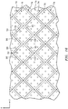
FIGS. 6 and 7 are cross-sectional illustrations of acoustic panels with alternative core configurations, in accordance with various embodiments; -
FIGS. 8 and 9 are side-sectional illustrations of acoustic panels with alternative core configurations, in accordance with various embodiments; -
FIG. 10 is a flow diagram of a method for forming a multi-degree of freedom acoustic panel, in accordance with various embodiments; -
FIG. 11 is a perspective illustration of a sidewall member, in accordance with various embodiments; -
FIG. 12 is a perspective illustration of a septum array member, in accordance with various embodiments; -
FIGS. 13-15 illustrate a sequence of steps for forming the septum array member ofFIG. 12 , in accordance with various embodiments; -
FIG. 16 is an illustration of a core with septum array members interposed with and connected to sidewall members, in accordance with various embodiments; -
FIG. 17 is a side-sectional illustration of the core ofFIG. 16 between a pair of skins, in accordance with various embodiments; -
FIG. 18 is a side-sectional illustration of an acoustic panel with an alternative core configuration, in accordance with various embodiments; -
FIGS. 19-21 illustrate a sequence of steps for forming the core ofFIG. 18 , in accordance with various embodiments; -
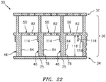
FIG. 22 is a side-sectional illustration of an acoustic panel with a still another alternative core configuration, in accordance with various embodiments; -
FIG. 23 is a cross-sectional illustration of another multi-degree of freedom acoustic panel, in accordance with various embodiments; -
FIG. 24 is a side-sectional illustration of another multi-degree of freedom acoustic panel, in accordance with various embodiments; and -
FIGS. 25 and 26 illustrate another sequence of steps for forming another septum array member, in accordance with various embodiments. -
FIG. 1 is a perspective illustration of a portion of a multi-degree of freedomacoustic panel 30; e.g., a double degree of freedom (DDoF) acoustic panel. Thisacoustic panel 30 is configured to attenuate sound (e.g., noise) generated, for example, by an aircraft propulsion system such as a turbofan propulsion system or a turbojet propulsion system. With such a configuration, theacoustic panel 30 may be configured with a nacelle of the propulsion system. Theacoustic panel 30, for example, may be configured as or with an inner or outer barrel, a translating sleeve of a thrust reverser, a blocker door, etc. Alternatively, theacoustic panel 30 may be configured with another component / structure of the aircraft such as its fuselage, a wing or a pylon for the propulsion system. Furthermore, theacoustic panel 30 may be configured to also or alternatively attenuate aircraft related sound other than that generated by the propulsion system. Theacoustic panel 30 of the present disclosure, of course, may alternatively be configured for non-aircraft sound attenuation applications. - The
acoustic panel 30 ofFIG. 1 extends longitudinally along a y-axis. Theacoustic panel 30 extends laterally along an x-axis. Theacoustic panel 30 extends vertically along a z-axis. The term "vertical" is used herein to describe a depthwise panel direction and is not limited to a gravitational up/down direction. Furthermore, for ease of illustration, the x-y plane is shown as a generally flat plane. However, in other embodiments, the x-y plane and, thus, theacoustic panel 30 may be curved and/or follow an undulating geometry. For example, the x-y plane and, thus, theacoustic panel 30 may be arcuate, cylindrical or conical with or without radial undulations. Thus, the vertical direction may change at different locations along the x-y plane. For example, for a cylindrical, conical or spherical acoustic panel, the vertical direction may be a radial direction, the longitudinal direction may be an axial (or circumferential) direction, and the lateral direction may be a circumferential (or axial) direction. - The
acoustic panel 30 includes a (e.g., acoustic) porous top skin 32 (e.g., a perforated face skin), a solid, non-perforated bottom skin 34 (e.g., a back skin) and acellular core 36. Note, the terms "top" and "bottom" are used in this disclosure to describe the relative position of an element as viewed in the figures. The present disclosure, however, is not limited to such an orientation. - Briefly, the
cellular core 36 is arranged and extends vertically between thetop skin 32 and thebottom skin 34. Thecellular core 36 is also connected to thetop skin 32 and thebottom skin 34. Thecellular core 36, for example, may be welded, brazed, fused, adhered and/or otherwise bonded to or integral with thetop skin 32 and/or thebottom skin 34 as discussed below in further detail. - The
top skin 32 ofFIG. 1 is configured as a relatively thin sheet or layer of material that extends longitudinally and laterally along the x-y plane. This top skin material may include, but is not limited to, a metal (e.g., sheet metal or metal foil), a polymer (e.g., thermoplastic or thermoset material), a fiber reinforced composite (e.g., fiberglass composite, carbon fiber composite, aramid fiber composite, etc.), or a combination thereof. In some embodiments, thetop skin 32 may be formed from woven fiber mesh (e.g., polymer or fiber mesh). Referring now toFIG. 3 , thetop skin 32 has avertical thickness 38, which extends vertically between opposing first skin top and bottom side surfaces. Thetop skin 32 includes a plurality ofpassages 40; e.g., perforations such as through-holes. Each of thesepassages 40 extends generally vertically through thetop skin 32 between its side surfaces. While thepassages 40 are described above and illustrated inFIG. 3 as through-holes for ease of description, one or more of thepassages 40 may also or alternatively be formed by one or more interconnected pores in the top skin material in alternative embodiments, for example, where the top skin is formed from woven fiber mesh. - The
bottom skin 34 ofFIG. 1 is configured as a relatively thin sheet or layer of (e.g., solid, continuous, uninterrupted and/or fluidly impervious) material that extends longitudinally and laterally along the x-y plane. This bottom skin material may include, but is not limited to, a metal (e.g., sheet metal or metal foil), a polymer (e.g., thermoplastic or thermoset material), a fiber reinforced composite (e.g., fiberglass composite, carbon fiber composite, aramid fiber composite, etc.), or a combination thereof. The bottom skin material may be the same as or different than the top skin material. Referring toFIG. 3 , thebottom skin 34 has avertical thickness 42, which extends vertically between opposing second skin top and bottom side surfaces. Thisvertical thickness 42 may be substantially equal to or different (e.g., greater or less) than thevertical thickness 38 of thetop skin 32. - Referring to
FIG. 1 , thecellular core 36 extends longitudinally and laterally along the x-y plane. Referring again toFIG. 3 , thecellular core 36 has avertical thickness 44, which extends vertically between opposing core sides respectively abutted against thetop skin 32 and thebottom skin 34. Thevertical thickness 44 may be substantially greater than thevertical thickness top skin 32 and/or thebottom skin 34. Thevertical thickness 44 of the core 36, for example, may be at least ten to forty times (10-40x) or more greater than thevertical thickness skin acoustic panel 30 of the present disclosure, however, is not limited to such an exemplary embodiment. - The
cellular core 36 ofFIGS. 2-4 includes a plurality of sidewalls 46 (e.g., corrugated sidewalls), a plurality ofcavities 48 and a plurality ofporous septums 50. Each of thesidewalls 46 ofFIG. 5 has a corrugated configuration. More particularly, each of thesidewalls 46 includes a plurality ofcorrugations 52 arranged in an end-to-end longitudinally extending array. Eachcorrugation 52 includes afirst sidewall segment 54 and asecond sidewall segment 56. A first (e.g., distal, exterior) end of thefirst sidewall segment 54 is connected (e.g., directly) to a first (e.g., distal, exterior) end of asecond sidewall segment 56 of a longitudinallyadjacent corrugation 52 in the array, thereby forming aninter-corrugation peak 58. A second (e.g., proximal, interior) end of thefirst sidewall segment 54 is connected (e.g., directly) to a second (e.g., proximal, interior) end of thesecond sidewall segment 56 of thesame corrugation 52, thereby forming anintra-corrugation peak 60. Thefirst sidewall segment 54 and thesecond sidewall segment 56 are angularly offset from one another (e.g., in the x-y plane) by anacute angle 62 such as, but not limited to, about (e.g., +/- 2°) or exactly ninety degrees (∼90°). Thefirst sidewall segment 54 has afirst length 64. Thesecond sidewall segment 56 has asecond length 66 that may be substantially (e.g., +/- 2%) or exactly equal to thefirst length 64. - The
sidewalls 46A-C (generally referred to as "46") ofFIG. 5 are arranged in a side-by-side laterally extending array so as to form thecavities 48 within thecellular core 36. For example, the inter-corrugation peaks 58 of thesidewall 46A are (e.g., longitudinally) aligned with and are connected to the intra-corrugation peaks 60 of a respective laterallyadjacent sidewall 46C. Furthermore, the intra-corrugation peaks 60 of thesidewall 46A are (e.g., longitudinally) aligned with and are connected to the inter-corrugation peaks 58 of another respective laterallyadjacent sidewall 46B. With this configuration, each adjacent pair of the sidewalls 46 forms a set (e.g., a longitudinal extending array) of one or more of thecavities 48 within thecellular core 36. - Each of the
cavities 48 extends laterally between a respective laterally adjacent pair of thesidewalls 46. For example, each of thecavities 48 extends laterally between thesidewall segments sidewalls sidewall segments sidewalls cavities 48 also extends longitudinally between thesidewall segments respective sidewall 46A and thesidewall segments respective sidewall 46B. - Each of the
cavities 48 may have a four-sided polygonal shape when viewed in a plane, which may be parallel to an x-y plane as well as the top and/orbottom skins 32 and 34 (seeFIG. 1 ). In the specific embodiment ofFIG. 5 , the four-sided polygonal shape is a square. However, in other embodiments, the four-sided polygonal shape may be a rectangle (seeFIG. 6 ), a diamond (seeFIG. 7 ) or otherwise. - Referring to
FIGS. 3 and 4 , each of thecavities 48 extends vertically through thecellular core 36 between and to thetop skin 32 and thebottom skin 34. Thus, each of thecavities 48 is fluidly coupled with one or morerespective passages 40 in thetop skin 32. In the embodiments ofFIGS. 2-4 , each of thecavities 48 is fluidly discrete; e.g., not fluidly coupled with any other of thecavities 48 within thecore 36. In other words, each of thesidewall segments - Referring to
FIGS. 2-4 , each of theseptums 50 is located within a respective one of thecavities 48. Each of theseptums 50 is configured to vertically divide therespective cavity 48 into a set (e.g., a pair) of fluidly coupled sub-cavities 48A and 48B. Each top sub-cavity 48A ofFIGS. 3 and 4 extends vertically between and to therespective septum 50 and thetop skin 32. Each bottom sub-cavity 48B ofFIGS. 3 and 4 extends vertically between and to therespective septum 50 and thebottom skin 34. - Each of the
septums 50 includes one ormore passages 68; e.g., perforations such as through-holes. Each of thesepassages 68 extends generally vertically through therespective septum 50. Thus, thepassages 68 are operable to fluidly couple the top andbottom sub-cavities septum 50. While thepassages 68 are described above and illustrated inFIGS. 3 and 4 as through-holes for ease of description, one or more of thepassages 68 may also or alternatively be formed by one or more interconnected pores in the septum material in alternative embodiments. - Referring to
FIG. 5 , each of theseptums 50 extends laterally between a respective laterally adjacent pair of thesidewalls 46. More particularly, each of theseptums 50 extends laterally between thesidewall segments sidewalls sidewall segments sidewalls septums 50 also extends longitudinally between thesidewall segments respective sidewall 46A and thesidewall segments respective sidewall 46B. - Each of the
septums 50 may have a four-sided polygonal shape when viewed in a plane, which may be parallel to an x-y plane as well as the top and/orbottom skins 32 and 34 (seeFIG. 1 ). In the specific embodiment ofFIG. 5 , the four-sided polygonal shape is a square. However, in other embodiments, the four-sided polygonal shape may be a rectangle (seeFIG. 6 ), a diamond (seeFIG. 7 ) or otherwise. - Referring to
FIG. 3 , eachseptum 50 is vertically displaced from thetop skin 32 by a non-zerofirst distance 70. Each septum is vertically displaced from thebottom skin 34 by a non-zerosecond distance 72. Thissecond distance 72 may be the same and thefirst distance 70 as shown inFIG. 3 . Alternatively, thesecond distance 72 may be less than thefirst distance 70 as shown inFIG. 8 . Still alternatively, thesecond distance 72 may be greater than thefirst distance 70 as shown inFIG. 9 . The first and thesecond distances panel 30 is intended to attenuate. -
FIG. 10 is a flow diagram of amethod 1000 for forming an acoustic panel such as, but not limited to, theacoustic panel 30 ofFIGS. 1-4 . Instep 1002, one ormore sidewall members 74 are formed. An embodiment of an exemplary one of thesidewall members 74 is shown inFIG. 11 . To form thesidewall member 74 ofFIG. 11 , a ply (e.g., a single sheet, strip or ribbon) ofmaterial 75 may be cut to size and is folded to generally have a configuration similar to the corrugated configuration of a respective one of thesidewalls 46; e.g., seeFIG. 2 . - In
step 1004, one or moreseptum array members 76 is formed. An embodiment of an exemplary one of theseptum array members 76 if shown inFIG. 12 . To form theseptum array member 76 ofFIG. 12 , a ply (e.g., a single sheet, strip or ribbon) ofmaterial 78 may be cut to size. Referring toFIG. 13 , one or more apertures 80 (e.g., cutouts) are formed (e.g., cut) in the ply ofmaterial 78 to provide the ply ofmaterial 78 with one or more castellations 82 (e.g., projections) and abase 84. Each of thecastellations 82 projects vertically out from a top edge of thebase 84.Adjacent castellations 82 are longitudinally separated by a respective one of theapertures 80. Thus, thecastellations 82 are interposed with theapertures 80. Referring toFIG. 14 , each of thecastellations 82 is folded along a respective fold line 86 (seeFIG. 13 ) such that, for example, thecastellation 82 is angularly offset from the base 84 by an acute angle such as, but not limited to, about (e.g., +/- 2°) or exactly ninety degrees (∼90°). Referring toFIG. 15 , thebase 84 is folded back and forth (e.g., accordion folded) along fold lines 88 (seeFIG. 13 ) to provide the base 84 with a corrugated configuration. Afree side edge 90 of eachcastellation 82 may then be attached (e.g., bonded) to arespective aperture edge 92 of thebase 84. A plurality of apertures 94 (seeFIG. 12 ) may then be formed in thecastellations 82, which apertures 94 will become thepassages 68 ofFIG. 2 . Of course, this perforation process may be performed earlier or later during thismethod 1000 in alternative embodiments. - In
step 1006, theseptum array members 76 are interposed with thesidewall members 74. For example, referring toFIG. 16 , eachseptum array member 76 is located laterally between and abutted against an adjacent pair of thesidewall members 74. - In
step 1008, thecellular core 36 is formed. In particular, themembers free edges castellation 82 are attached to a respective one of thesidewall members 74 at interfaces. One or more of the remainingedges castellation 82 may similarly be attached to another respective one of thesidewall members 74 at interfaces. In addition or alternatively, referring toFIG. 17 , thebase 84 may be attached to therespective sidewall member 74. In this manner, the (e.g., single) ply of foldedmaterial 78 forming eachseptum array member 76 may solely and completely define a respective longitudinal array of theseptums 50. Thus, eachseptum 50 may be configured from (e.g., only include) arespective castellation 82. The ply of foldedmaterial 78 also forms a bottom portion of arespective sidewall 46 with arespective sidewall member 74. - In
step 1010, thecore 36 is connected between the top and the bottom skins 32 and 34 as shown, for example, inFIG. 17 . More particularly, thecellular core 36 is positioned between thetop skin 32 and thebottom skin 34. Thecellular core 36 is then attached to theskins top skin 32 may be perforated before or after thecellular core 36 is attached to thetop skin 32 - With the configuration of
FIG. 17 , thebase 84 of each ply of folded material (e.g., 78A) vertically contacts and may be attached to thebottom skin 34 at an interface (e.g., 102) between the sidewall (e.g., 46A) and thebottom skin 34. By contrast, the respective ply of folded material (e.g., 78A) is vertically displaced from thebottom skin 34 at an interface (e.g., 104) between the sidewall (e.g., 46B) and thebottom skin 34. Thus, at the interface (e.g., 104), the ply of folded material (e.g., 78A) does not contact thebottom skin 34 as the elements (e.g., 78A and 34) are completely vertically separated by a vertical gap. - In the embodiments described above, each
septum 50 has a single ply layer construction. In other embodiments, however, one or more of theseptums 50 may each have a multi (e.g., two) ply layer construction as illustrated, for example, inFIG. 18 . More particularly, eachseptum 50 may be formed by at least two overlapping and abutting portions of a ply of material. Such a multi ply layer construction may be provided by cutting a ply ofmaterial 106 alongcut lines 108 and then folding the cut ply of material alongfold lines FIGS. 19-21 . - In some embodiments, one or more of the
castellations 82 may each be configured with atab 114 as shown inFIG. 22 . Thistab 114 may facilitate the attachment of thecastellation 82 to thesidewall member 74 opposite thebase 84. Thetab 114 also serves to form a portion of therespective sidewall 46. Eachtab 114 ofFIG. 22 has avertical height 116 that is less than avertical height 118 of thebase 84. Thus, none of thetabs 114 contacts or is directly attached to thebottom skin 34. - In the embodiments described above, each ply of folded
material 78 forming a respectiveseptum array member 76 is described as contacting and/or being attached to thebottom skin 34. In alternative embodiments, however, theseptum array member 76 may be flipped such that the ply of foldedmaterial 78 contacts and may be attached to thetop skin 32. - The
cellular core 36 and its plies of material may include, but is not limited to, a metal (e.g., sheet metal or metal foil), a polymer (e.g., thermoplastic or thermoset material), a fiber reinforced composite (e.g., fiberglass composite, carbon fiber composite, aramid fiber composite, etc.), or a combination thereof. In some embodiments, thecellular core 36 and its plies of material may be formed from woven fiber mesh (e.g., polymer or fiber mesh). The core / ply material may be the same as or different than the top skin material and/or the bottom skin material. - In some embodiments, each peak 58, 60 may be configured from a sharp bend between the
respective sidewall segments FIG. 5 . However, in other embodiments, one or more of thepeaks 58 and/or 60 may each be configured from a small radius bend between therespective sidewall segments FIG. 23 . - Referring to
FIG. 24 , in some embodiments, theseptum 50 heights may vary between laterallyadjacent cavities 48. - Referring to
FIGS. 25 and 26 , in some embodiments, a perimeter of one or more of theseptums 50 may be fully capped; e.g., includematerial tabs 114' and 114" on three sides of a septum base 82'. - While various embodiments of the present invention have been disclosed, it will be apparent to those of ordinary skill in the art that many more embodiments and implementations are possible within the scope of the invention. For example, the present invention as described herein includes several aspects and embodiments that include particular features. Although these features may be described individually, it is within the scope of the present invention that some or all of these features may be combined with any one of the aspects and remain within the scope of the invention. Accordingly, the present invention is not to be restricted except in light of the attached claims and their equivalents.
Claims (15)
- An acoustic panel (30), comprising:a first skin (32), a second skin (34) and a cellular core (36) vertically between and connected to the first skin (32) and the second skin (34), the cellular core (36) comprising a plurality of cavities (48), a plurality of sidewalls (46; 46A, 46B, 46C) and a plurality of septums (50);each of the plurality of cavities (48) extending vertically through the cellular core (36) between the first skin (32) and the second skin (34), and each of the plurality of cavities (48) extending laterally within the cellular core (36) between a respective laterally adjacent pair of the plurality of sidewalls (46...46C);each of the plurality of septums (50) vertically dividing a respective one of the plurality of cavities (48) into a set of fluidly coupled sub-cavities (48A, 48B);a set of the plurality of septums (50) formed by a ply of folded material (78; 106); andeach of the set of the plurality of septums (50) having a four-sided polygonal shape when viewed in a plane (x-y) that is parallel to the first skin (32).
- The acoustic panel (30) of claim 1, wherein the four-sided polygonal shape is a square.
- The acoustic panel (30) of claim 1 or 2, wherein the set of the plurality of septums (50) are arranged in a longitudinal extending array.
- The acoustic panel (30) of any preceding claim, wherein
the plurality of sidewalls (46...46C) comprise a first sidewall (46A) and a second sidewall (46B);
the plurality of cavities (48) comprise a first cavity (48) that extends laterally between the first sidewall (46A) and the second sidewall (46B);
the plurality of septums (50) comprise a first septum (50) within the first cavity (48);
the ply of folded material (78; 106) forms the first septum (50);
the first sidewall (46A) comprises a second ply of material (75); and
the second sidewall (46B) comprises a third ply of material (75). - The acoustic panel (30) of claim 4, wherein the first sidewall (46A) further comprises a first portion (84) of the ply of folded material (78; 106).
- The acoustic panel (30) of claim 5, wherein the second sidewall (46B) further comprises a second portion (114) of the ply of folded material (106), wherein the first portion (84) optionally has a first vertical height (118), and the second portion (114) optionally has a second vertical height (116) that is different from the first vertical height (118).
- The acoustic panel (30) of claim 6, wherein the first portion (84) vertically contacts the second skin (34), and the second portion (114) does not contact the second skin (34).
- The acoustic panel (30) of claim 5 or 6, wherein the first portion (84) vertically contacts the second skin (34).
- The acoustic panel (30) of any preceding claim, wherein the ply of folded material (78; 106) comprises one or more of metal, polymer, fiber-reinforced composite and woven fiber mesh.
- The acoustic panel (30) of any preceding claim, wherein the first skin (32) is a perforated first skin (32).
- The acoustic panel (30) of any preceding claim, wherein a second set of the plurality of septums (50) are formed by a second ply of folded material, and the second set of the plurality of septums (50) is laterally adjacent the set of the plurality of septums (50).
- The acoustic panel (30) of any preceding claim, wherein
the plurality of septums (50) comprises a first septum (50); and
the first septum (50) comprises a first portion of the ply of folded material (106) and a second portion of the ply of folded material (106) that overlaps and lays against the first portion of the ply of folded material (106). - An acoustic panel (30), comprising:a first skin (32), a second skin (34) and a cellular core (36) vertically between and connected to the first skin (32) and the second skin (34), the cellular core (36) comprising a plurality of cavities (48), a plurality of sidewalls (46; 46A, 46B, 46C) and a plurality of septums (50);each of the plurality of cavities (48) extending vertically through the cellular core (36) between the first skin (32) and the second skin (34), and each of the plurality of cavities (48) extending laterally within the cellular core (36) between a respective laterally adjacent pair of the plurality of sidewalls (46...46C);each of the plurality of septums (50) vertically dividing a respective one of the plurality of cavities (48) into a set of fluidly coupled sub-cavities (48A, 48B);the plurality of sidewalls (46...46C) comprising a first sidewall (46A) and a second sidewall (46B);the plurality of cavities (48) comprising a first cavity (48) that extends laterally between the first sidewall (46A) and the second sidewall (46B);the plurality of septums (50) comprising a first septum (50) within the first cavity (48);wherein a ply of folded material (78; 106) forms at least the first septum (50) and a portion (84) of the first sidewall (46A); andthe ply of folded material (78; 106) contacts the second skin (34) at an interface between the first sidewall (46A) and the second skin (34), and is separated from the second skin (34) at an interface between the second sidewall (46B) and the second skin (34).
- The acoustic panel (30) of claim 13, wherein the ply of folded material (106) further forms a portion of the second sidewall (46B); and/or
wherein the ply of folded material (78; 106) further forms a second of the plurality of septums (50) that is longitudinally adjacent the first septum (50). - An acoustic panel (30), comprising:a first skin (32), a second skin (34) and a cellular core (36) vertically between and connected to the first skin (32) and the second skin (34), the cellular core (36) comprising a plurality of cavities (48), a plurality of sidewalls (46; 46A, 46B, 46C) and a plurality of septums (50);each of the plurality of cavities (48) extending vertically through the cellular core (36) between the first skin (32) and the second skin (34), and each of the plurality of cavities (48) extending laterally within the cellular core (36) between a respective laterally adjacent pair of the plurality of sidewalls (46...46C);each of the plurality of septums (50) vertically dividing a respective one of the plurality of cavities (48) into a set of fluidly coupled sub-cavities (48A, 48B); anda set of the plurality of septums (50) formed by a ply of folded material (106);wherein the plurality of septums (50) comprises a first septum (50); andwherein the first septum (50) comprises a first portion of the ply of folded material (106) and a second portion of the ply of folded material (106) that lays against the first portion of the ply of folded material (106).
Applications Claiming Priority (1)
| Application Number | Priority Date | Filing Date | Title |
|---|---|---|---|
| US16/108,710 US11359577B2 (en) | 2018-08-22 | 2018-08-22 | Multi-degree of freedom acoustic panel |
Publications (3)
| Publication Number | Publication Date |
|---|---|
| EP3614373A2 true EP3614373A2 (en) | 2020-02-26 |
| EP3614373A3 EP3614373A3 (en) | 2020-07-29 |
| EP3614373B1 EP3614373B1 (en) | 2023-07-05 |
Family
ID=67659743
Family Applications (1)
| Application Number | Title | Priority Date | Filing Date |
|---|---|---|---|
| EP19192920.7A Active EP3614373B1 (en) | 2018-08-22 | 2019-08-21 | Multi-degree of freedom acoustic panel |
Country Status (2)
| Country | Link |
|---|---|
| US (1) | US11359577B2 (en) |
| EP (1) | EP3614373B1 (en) |
Cited By (1)
| Publication number | Priority date | Publication date | Assignee | Title |
|---|---|---|---|---|
| FR3143169A1 (en) * | 2022-12-07 | 2024-06-14 | Safran Nacelles | OPTIMIZED CELL CORE AND SOUND ATTENUATION PANEL INCLUDING IT FOR AN AIRCRAFT TURBOMACHINE |
Families Citing this family (13)
| Publication number | Priority date | Publication date | Assignee | Title |
|---|---|---|---|---|
| FR3103787A1 (en) * | 2019-12-03 | 2021-06-04 | Airbus Operations | Multi-layer heat shield aircraft engine mast rear fairing. |
| FR3107856B1 (en) * | 2020-03-04 | 2022-02-04 | Safran Nacelles | Process for manufacturing a honeycomb core structure for a turbojet engine nacelle |
| US11715450B2 (en) | 2020-12-22 | 2023-08-01 | Rohr, Inc. | Acoustic panel core cell with funnel shaped septum |
| US11965465B2 (en) | 2020-12-22 | 2024-04-23 | Rohr, Inc. | Acoustic panel with multiple layer corrugated core |
| US11869472B2 (en) | 2021-08-02 | 2024-01-09 | Rohr, Inc. | Acoustic panel with reconfigurable chamber constrictions |
| EP4206448B1 (en) | 2022-01-04 | 2025-07-09 | Rohr, Inc. | Multi-core acoustic panel for an aircraft propulsion system |
| EP4302980B1 (en) | 2022-07-08 | 2025-04-23 | Rohr, Inc. | Forming pattern for cellular core by folding material |
| US12163472B2 (en) | 2022-09-02 | 2024-12-10 | Rohr, Inc. | Engine exhaust nozzle with acoustic attenuation |
| US20240328361A1 (en) * | 2023-03-31 | 2024-10-03 | Pratt & Whitney Canada Corp. | Acoustic panel with non-linear variable percentage of open area |
| US20240331674A1 (en) * | 2023-03-31 | 2024-10-03 | Pratt & Whitney Canada Corp. | Acoustic panel with non-linear variable percentage of open area |
| US20240343413A1 (en) * | 2023-04-17 | 2024-10-17 | The Boeing Company | Cellular Core for Aircraft Acoustic Panel and Method of Manufacture |
| FR3151933B1 (en) * | 2023-08-04 | 2025-11-28 | Safran Nacelles | Honeycomb structure for an acoustic panel |
| US20250282485A1 (en) * | 2024-03-11 | 2025-09-11 | Rohr, Inc. | Aircraft acoustic panel with perforated cavity walls |
Family Cites Families (12)
| Publication number | Priority date | Publication date | Assignee | Title |
|---|---|---|---|---|
| FR2781719B1 (en) | 1998-07-30 | 2000-09-08 | Hispano Suiza Sa | HONEYCOMB STRUCTURE, IN PARTICULAR FOR SOUND ABSORPTION, AND MANUFACTURING METHOD THEREOF |
| FR2815900B1 (en) | 2000-10-31 | 2003-07-18 | Eads Airbus Sa | NOISE REDUCING SANDWICH PANEL, ESPECIALLY FOR AN AIRCRAFT TURBOREACTOR |
| DE102004053383A1 (en) | 2004-11-02 | 2006-05-04 | Eads Deutschland Gmbh | Acoustic absorber for aircraft engines |
| US8413761B2 (en) | 2005-04-04 | 2013-04-09 | Hexcel Corporation | Acoustic honeycomb with perforated septum caps |
| US7510052B2 (en) | 2005-04-04 | 2009-03-31 | Hexcel Corporation | Acoustic septum cap honeycomb |
| US9592918B2 (en) | 2014-06-23 | 2017-03-14 | Rohr, Inc. | Acoustic liner |
| DE102014011775B4 (en) | 2014-08-09 | 2016-08-11 | Florian Tuczek | Folding structure, component connection, sandwich panel, as well as folding method and tool |
| US9469985B1 (en) | 2015-05-11 | 2016-10-18 | Hexcel Corporation | Acoustic structures with multiple degrees of freedom |
| WO2017117153A1 (en) | 2015-12-27 | 2017-07-06 | Massachusetts Institute Of Technology | Design and fabrication of three-dimensional kirigami structures with tunable properties |
| US9764818B2 (en) * | 2016-02-10 | 2017-09-19 | Rohr, Inc. | Structural, cellular core with corrugated support walls |
| US9732677B1 (en) | 2016-05-12 | 2017-08-15 | Rohr, Inc. | Broadband acoustic panels coupled with large secondary cavities to attenuate low frequencies |
| US11286957B2 (en) * | 2018-07-02 | 2022-03-29 | Rohr, Inc. | Method for inserting septum into acoustic liner |
-
2018
- 2018-08-22 US US16/108,710 patent/US11359577B2/en active Active
-
2019
- 2019-08-21 EP EP19192920.7A patent/EP3614373B1/en active Active
Cited By (1)
| Publication number | Priority date | Publication date | Assignee | Title |
|---|---|---|---|---|
| FR3143169A1 (en) * | 2022-12-07 | 2024-06-14 | Safran Nacelles | OPTIMIZED CELL CORE AND SOUND ATTENUATION PANEL INCLUDING IT FOR AN AIRCRAFT TURBOMACHINE |
Also Published As
| Publication number | Publication date |
|---|---|
| US11359577B2 (en) | 2022-06-14 |
| EP3614373B1 (en) | 2023-07-05 |
| EP3614373A3 (en) | 2020-07-29 |
| US20200063691A1 (en) | 2020-02-27 |
Similar Documents
| Publication | Publication Date | Title |
|---|---|---|
| EP3614373B1 (en) | Multi-degree of freedom acoustic panel | |
| EP3422342B1 (en) | Acoustic panel with folding chamber | |
| EP3205574B1 (en) | Structural, cellular core with corrugated support walls | |
| EP3324400B1 (en) | Acoustic panel with sidewall stringers | |
| EP3324401B1 (en) | Acoustic panel with sidewall stringers | |
| US11014331B2 (en) | Structured panel with non-parallel cavity walls | |
| EP3594936B1 (en) | Structured panel with integrated skin and sidewalls | |
| US9708930B2 (en) | Multi-degree of freedom acoustic panel | |
| US10994856B2 (en) | Structural panel with splice joint between adjacent core structures | |
| EP3748627B1 (en) | Acoustic panel with one or more structural stiffeners | |
| US11715450B2 (en) | Acoustic panel core cell with funnel shaped septum | |
| US10695986B2 (en) | Method for forming a structural panel | |
| US10676171B2 (en) | Structural panel with splice joint between adjacent core structures | |
| EP3671727B1 (en) | Forming a structured panel with one or more structural reinforcements | |
| EP4030419B1 (en) | Acoustic panel core with multi-material and/or multi-layered construction | |
| EP4243010B1 (en) | Forming acoustic panel with multi-layered septum(s) | |
| EP4302980B1 (en) | Forming pattern for cellular core by folding material | |
| US20180361684A1 (en) | Process for forming a fiber-reinforced composite structure |
Legal Events
| Date | Code | Title | Description |
|---|---|---|---|
| PUAI | Public reference made under article 153(3) epc to a published international application that has entered the european phase |
Free format text: ORIGINAL CODE: 0009012 |
|
| STAA | Information on the status of an ep patent application or granted ep patent |
Free format text: STATUS: THE APPLICATION HAS BEEN PUBLISHED |
|
| AK | Designated contracting states |
Kind code of ref document: A2 Designated state(s): AL AT BE BG CH CY CZ DE DK EE ES FI FR GB GR HR HU IE IS IT LI LT LU LV MC MK MT NL NO PL PT RO RS SE SI SK SM TR |
|
| AX | Request for extension of the european patent |
Extension state: BA ME |
|
| PUAL | Search report despatched |
Free format text: ORIGINAL CODE: 0009013 |
|
| AK | Designated contracting states |
Kind code of ref document: A3 Designated state(s): AL AT BE BG CH CY CZ DE DK EE ES FI FR GB GR HR HU IE IS IT LI LT LU LV MC MK MT NL NO PL PT RO RS SE SI SK SM TR |
|
| AX | Request for extension of the european patent |
Extension state: BA ME |
|
| RIC1 | Information provided on ipc code assigned before grant |
Ipc: G10K 11/168 20060101ALI20200622BHEP Ipc: G10K 11/172 20060101AFI20200622BHEP |
|
| STAA | Information on the status of an ep patent application or granted ep patent |
Free format text: STATUS: REQUEST FOR EXAMINATION WAS MADE |
|
| 17P | Request for examination filed |
Effective date: 20210129 |
|
| RBV | Designated contracting states (corrected) |
Designated state(s): AL AT BE BG CH CY CZ DE DK EE ES FI FR GB GR HR HU IE IS IT LI LT LU LV MC MK MT NL NO PL PT RO RS SE SI SK SM TR |
|
| STAA | Information on the status of an ep patent application or granted ep patent |
Free format text: STATUS: EXAMINATION IS IN PROGRESS |
|
| 17Q | First examination report despatched |
Effective date: 20220926 |
|
| GRAP | Despatch of communication of intention to grant a patent |
Free format text: ORIGINAL CODE: EPIDOSNIGR1 |
|
| STAA | Information on the status of an ep patent application or granted ep patent |
Free format text: STATUS: GRANT OF PATENT IS INTENDED |
|
| INTG | Intention to grant announced |
Effective date: 20230118 |
|
| GRAS | Grant fee paid |
Free format text: ORIGINAL CODE: EPIDOSNIGR3 |
|
| GRAA | (expected) grant |
Free format text: ORIGINAL CODE: 0009210 |
|
| STAA | Information on the status of an ep patent application or granted ep patent |
Free format text: STATUS: THE PATENT HAS BEEN GRANTED |
|
| AK | Designated contracting states |
Kind code of ref document: B1 Designated state(s): AL AT BE BG CH CY CZ DE DK EE ES FI FR GB GR HR HU IE IS IT LI LT LU LV MC MK MT NL NO PL PT RO RS SE SI SK SM TR |
|
| REG | Reference to a national code |
Ref country code: CH Ref legal event code: EP |
|
| REG | Reference to a national code |
Ref country code: AT Ref legal event code: REF Ref document number: 1585576 Country of ref document: AT Kind code of ref document: T Effective date: 20230715 |
|
| REG | Reference to a national code |
Ref country code: DE Ref legal event code: R096 Ref document number: 602019032028 Country of ref document: DE |
|
| REG | Reference to a national code |
Ref country code: IE Ref legal event code: FG4D |
|
| REG | Reference to a national code |
Ref country code: LT Ref legal event code: MG9D |
|
| REG | Reference to a national code |
Ref country code: NL Ref legal event code: MP Effective date: 20230705 |
|
| REG | Reference to a national code |
Ref country code: AT Ref legal event code: MK05 Ref document number: 1585576 Country of ref document: AT Kind code of ref document: T Effective date: 20230705 |
|
| PG25 | Lapsed in a contracting state [announced via postgrant information from national office to epo] |
Ref country code: NL Free format text: LAPSE BECAUSE OF FAILURE TO SUBMIT A TRANSLATION OF THE DESCRIPTION OR TO PAY THE FEE WITHIN THE PRESCRIBED TIME-LIMIT Effective date: 20230705 |
|
| PG25 | Lapsed in a contracting state [announced via postgrant information from national office to epo] |
Ref country code: GR Free format text: LAPSE BECAUSE OF FAILURE TO SUBMIT A TRANSLATION OF THE DESCRIPTION OR TO PAY THE FEE WITHIN THE PRESCRIBED TIME-LIMIT Effective date: 20231006 |
|
| PG25 | Lapsed in a contracting state [announced via postgrant information from national office to epo] |
Ref country code: ES Free format text: LAPSE BECAUSE OF FAILURE TO SUBMIT A TRANSLATION OF THE DESCRIPTION OR TO PAY THE FEE WITHIN THE PRESCRIBED TIME-LIMIT Effective date: 20230705 |
|
| PG25 | Lapsed in a contracting state [announced via postgrant information from national office to epo] |
Ref country code: IS Free format text: LAPSE BECAUSE OF FAILURE TO SUBMIT A TRANSLATION OF THE DESCRIPTION OR TO PAY THE FEE WITHIN THE PRESCRIBED TIME-LIMIT Effective date: 20231105 |
|
| PG25 | Lapsed in a contracting state [announced via postgrant information from national office to epo] |
Ref country code: SE Free format text: LAPSE BECAUSE OF FAILURE TO SUBMIT A TRANSLATION OF THE DESCRIPTION OR TO PAY THE FEE WITHIN THE PRESCRIBED TIME-LIMIT Effective date: 20230705 Ref country code: RS Free format text: LAPSE BECAUSE OF FAILURE TO SUBMIT A TRANSLATION OF THE DESCRIPTION OR TO PAY THE FEE WITHIN THE PRESCRIBED TIME-LIMIT Effective date: 20230705 Ref country code: PT Free format text: LAPSE BECAUSE OF FAILURE TO SUBMIT A TRANSLATION OF THE DESCRIPTION OR TO PAY THE FEE WITHIN THE PRESCRIBED TIME-LIMIT Effective date: 20231106 Ref country code: NO Free format text: LAPSE BECAUSE OF FAILURE TO SUBMIT A TRANSLATION OF THE DESCRIPTION OR TO PAY THE FEE WITHIN THE PRESCRIBED TIME-LIMIT Effective date: 20231005 Ref country code: LV Free format text: LAPSE BECAUSE OF FAILURE TO SUBMIT A TRANSLATION OF THE DESCRIPTION OR TO PAY THE FEE WITHIN THE PRESCRIBED TIME-LIMIT Effective date: 20230705 Ref country code: LT Free format text: LAPSE BECAUSE OF FAILURE TO SUBMIT A TRANSLATION OF THE DESCRIPTION OR TO PAY THE FEE WITHIN THE PRESCRIBED TIME-LIMIT Effective date: 20230705 Ref country code: IS Free format text: LAPSE BECAUSE OF FAILURE TO SUBMIT A TRANSLATION OF THE DESCRIPTION OR TO PAY THE FEE WITHIN THE PRESCRIBED TIME-LIMIT Effective date: 20231105 Ref country code: HR Free format text: LAPSE BECAUSE OF FAILURE TO SUBMIT A TRANSLATION OF THE DESCRIPTION OR TO PAY THE FEE WITHIN THE PRESCRIBED TIME-LIMIT Effective date: 20230705 Ref country code: GR Free format text: LAPSE BECAUSE OF FAILURE TO SUBMIT A TRANSLATION OF THE DESCRIPTION OR TO PAY THE FEE WITHIN THE PRESCRIBED TIME-LIMIT Effective date: 20231006 Ref country code: FI Free format text: LAPSE BECAUSE OF FAILURE TO SUBMIT A TRANSLATION OF THE DESCRIPTION OR TO PAY THE FEE WITHIN THE PRESCRIBED TIME-LIMIT Effective date: 20230705 Ref country code: ES Free format text: LAPSE BECAUSE OF FAILURE TO SUBMIT A TRANSLATION OF THE DESCRIPTION OR TO PAY THE FEE WITHIN THE PRESCRIBED TIME-LIMIT Effective date: 20230705 Ref country code: AT Free format text: LAPSE BECAUSE OF FAILURE TO SUBMIT A TRANSLATION OF THE DESCRIPTION OR TO PAY THE FEE WITHIN THE PRESCRIBED TIME-LIMIT Effective date: 20230705 |
|
| PG25 | Lapsed in a contracting state [announced via postgrant information from national office to epo] |
Ref country code: PL Free format text: LAPSE BECAUSE OF FAILURE TO SUBMIT A TRANSLATION OF THE DESCRIPTION OR TO PAY THE FEE WITHIN THE PRESCRIBED TIME-LIMIT Effective date: 20230705 |
|
| REG | Reference to a national code |
Ref country code: CH Ref legal event code: PL |
|
| REG | Reference to a national code |
Ref country code: DE Ref legal event code: R097 Ref document number: 602019032028 Country of ref document: DE |
|
| PG25 | Lapsed in a contracting state [announced via postgrant information from national office to epo] |
Ref country code: LU Free format text: LAPSE BECAUSE OF NON-PAYMENT OF DUE FEES Effective date: 20230821 |
|
| PG25 | Lapsed in a contracting state [announced via postgrant information from national office to epo] |
Ref country code: SM Free format text: LAPSE BECAUSE OF FAILURE TO SUBMIT A TRANSLATION OF THE DESCRIPTION OR TO PAY THE FEE WITHIN THE PRESCRIBED TIME-LIMIT Effective date: 20230705 Ref country code: RO Free format text: LAPSE BECAUSE OF FAILURE TO SUBMIT A TRANSLATION OF THE DESCRIPTION OR TO PAY THE FEE WITHIN THE PRESCRIBED TIME-LIMIT Effective date: 20230705 Ref country code: LU Free format text: LAPSE BECAUSE OF NON-PAYMENT OF DUE FEES Effective date: 20230821 Ref country code: EE Free format text: LAPSE BECAUSE OF FAILURE TO SUBMIT A TRANSLATION OF THE DESCRIPTION OR TO PAY THE FEE WITHIN THE PRESCRIBED TIME-LIMIT Effective date: 20230705 Ref country code: DK Free format text: LAPSE BECAUSE OF FAILURE TO SUBMIT A TRANSLATION OF THE DESCRIPTION OR TO PAY THE FEE WITHIN THE PRESCRIBED TIME-LIMIT Effective date: 20230705 Ref country code: CZ Free format text: LAPSE BECAUSE OF FAILURE TO SUBMIT A TRANSLATION OF THE DESCRIPTION OR TO PAY THE FEE WITHIN THE PRESCRIBED TIME-LIMIT Effective date: 20230705 Ref country code: MC Free format text: LAPSE BECAUSE OF FAILURE TO SUBMIT A TRANSLATION OF THE DESCRIPTION OR TO PAY THE FEE WITHIN THE PRESCRIBED TIME-LIMIT Effective date: 20230705 Ref country code: SK Free format text: LAPSE BECAUSE OF FAILURE TO SUBMIT A TRANSLATION OF THE DESCRIPTION OR TO PAY THE FEE WITHIN THE PRESCRIBED TIME-LIMIT Effective date: 20230705 Ref country code: CH Free format text: LAPSE BECAUSE OF NON-PAYMENT OF DUE FEES Effective date: 20230831 |
|
| REG | Reference to a national code |
Ref country code: BE Ref legal event code: MM Effective date: 20230831 |
|
| PLBE | No opposition filed within time limit |
Free format text: ORIGINAL CODE: 0009261 |
|
| STAA | Information on the status of an ep patent application or granted ep patent |
Free format text: STATUS: NO OPPOSITION FILED WITHIN TIME LIMIT |
|
| REG | Reference to a national code |
Ref country code: IE Ref legal event code: MM4A |
|
| PG25 | Lapsed in a contracting state [announced via postgrant information from national office to epo] |
Ref country code: IT Free format text: LAPSE BECAUSE OF FAILURE TO SUBMIT A TRANSLATION OF THE DESCRIPTION OR TO PAY THE FEE WITHIN THE PRESCRIBED TIME-LIMIT Effective date: 20230705 |
|
| 26N | No opposition filed |
Effective date: 20240408 |
|
| PG25 | Lapsed in a contracting state [announced via postgrant information from national office to epo] |
Ref country code: IE Free format text: LAPSE BECAUSE OF NON-PAYMENT OF DUE FEES Effective date: 20230821 |
|
| PG25 | Lapsed in a contracting state [announced via postgrant information from national office to epo] |
Ref country code: IE Free format text: LAPSE BECAUSE OF NON-PAYMENT OF DUE FEES Effective date: 20230821 Ref country code: SI Free format text: LAPSE BECAUSE OF FAILURE TO SUBMIT A TRANSLATION OF THE DESCRIPTION OR TO PAY THE FEE WITHIN THE PRESCRIBED TIME-LIMIT Effective date: 20230705 |
|
| PG25 | Lapsed in a contracting state [announced via postgrant information from national office to epo] |
Ref country code: BE Free format text: LAPSE BECAUSE OF NON-PAYMENT OF DUE FEES Effective date: 20230831 |
|
| PG25 | Lapsed in a contracting state [announced via postgrant information from national office to epo] |
Ref country code: BG Free format text: LAPSE BECAUSE OF FAILURE TO SUBMIT A TRANSLATION OF THE DESCRIPTION OR TO PAY THE FEE WITHIN THE PRESCRIBED TIME-LIMIT Effective date: 20230705 |
|
| PG25 | Lapsed in a contracting state [announced via postgrant information from national office to epo] |
Ref country code: BG Free format text: LAPSE BECAUSE OF FAILURE TO SUBMIT A TRANSLATION OF THE DESCRIPTION OR TO PAY THE FEE WITHIN THE PRESCRIBED TIME-LIMIT Effective date: 20230705 |
|
| PG25 | Lapsed in a contracting state [announced via postgrant information from national office to epo] |
Ref country code: CY Free format text: LAPSE BECAUSE OF FAILURE TO SUBMIT A TRANSLATION OF THE DESCRIPTION OR TO PAY THE FEE WITHIN THE PRESCRIBED TIME-LIMIT; INVALID AB INITIO Effective date: 20190821 |
|
| PG25 | Lapsed in a contracting state [announced via postgrant information from national office to epo] |
Ref country code: HU Free format text: LAPSE BECAUSE OF FAILURE TO SUBMIT A TRANSLATION OF THE DESCRIPTION OR TO PAY THE FEE WITHIN THE PRESCRIBED TIME-LIMIT; INVALID AB INITIO Effective date: 20190821 |
|
| PGFP | Annual fee paid to national office [announced via postgrant information from national office to epo] |
Ref country code: DE Payment date: 20250724 Year of fee payment: 7 |
|
| PGFP | Annual fee paid to national office [announced via postgrant information from national office to epo] |
Ref country code: GB Payment date: 20250725 Year of fee payment: 7 |
|
| PGFP | Annual fee paid to national office [announced via postgrant information from national office to epo] |
Ref country code: FR Payment date: 20250725 Year of fee payment: 7 |
|
| PG25 | Lapsed in a contracting state [announced via postgrant information from national office to epo] |
Ref country code: TR Free format text: LAPSE BECAUSE OF FAILURE TO SUBMIT A TRANSLATION OF THE DESCRIPTION OR TO PAY THE FEE WITHIN THE PRESCRIBED TIME-LIMIT Effective date: 20230705 |
|
| P01 | Opt-out of the competence of the unified patent court (upc) registered |
Free format text: CASE NUMBER: UPC_APP_0018981_3614373/2025 Effective date: 20251222 |