EP3614342A1 - Trajectory identification device, program, and trajectory identification method - Google Patents
Trajectory identification device, program, and trajectory identification method Download PDFInfo
- Publication number
- EP3614342A1 EP3614342A1 EP18788117.2A EP18788117A EP3614342A1 EP 3614342 A1 EP3614342 A1 EP 3614342A1 EP 18788117 A EP18788117 A EP 18788117A EP 3614342 A1 EP3614342 A1 EP 3614342A1
- Authority
- EP
- European Patent Office
- Prior art keywords
- point
- image
- unit
- searching unit
- line segment
- Prior art date
- Legal status (The legal status is an assumption and is not a legal conclusion. Google has not performed a legal analysis and makes no representation as to the accuracy of the status listed.)
- Withdrawn
Links
Images



Classifications
-
- G—PHYSICS
- G06—COMPUTING OR CALCULATING; COUNTING
- G06V—IMAGE OR VIDEO RECOGNITION OR UNDERSTANDING
- G06V20/00—Scenes; Scene-specific elements
- G06V20/35—Categorising the entire scene, e.g. birthday party or wedding scene
- G06V20/38—Outdoor scenes
-
- B—PERFORMING OPERATIONS; TRANSPORTING
- B61—RAILWAYS
- B61L—GUIDING RAILWAY TRAFFIC; ENSURING THE SAFETY OF RAILWAY TRAFFIC
- B61L23/00—Control, warning or like safety means along the route or between vehicles or trains
- B61L23/04—Control, warning or like safety means along the route or between vehicles or trains for monitoring the mechanical state of the route
-
- G—PHYSICS
- G06—COMPUTING OR CALCULATING; COUNTING
- G06T—IMAGE DATA PROCESSING OR GENERATION, IN GENERAL
- G06T3/00—Geometric image transformations in the plane of the image
- G06T3/04—Context-preserving transformations, e.g. by using an importance map
-
- G—PHYSICS
- G06—COMPUTING OR CALCULATING; COUNTING
- G06T—IMAGE DATA PROCESSING OR GENERATION, IN GENERAL
- G06T7/00—Image analysis
-
- G—PHYSICS
- G06—COMPUTING OR CALCULATING; COUNTING
- G06T—IMAGE DATA PROCESSING OR GENERATION, IN GENERAL
- G06T7/00—Image analysis
- G06T7/60—Analysis of geometric attributes
-
- G—PHYSICS
- G06—COMPUTING OR CALCULATING; COUNTING
- G06V—IMAGE OR VIDEO RECOGNITION OR UNDERSTANDING
- G06V10/00—Arrangements for image or video recognition or understanding
- G06V10/20—Image preprocessing
- G06V10/25—Determination of region of interest [ROI] or a volume of interest [VOI]
-
- G—PHYSICS
- G06—COMPUTING OR CALCULATING; COUNTING
- G06V—IMAGE OR VIDEO RECOGNITION OR UNDERSTANDING
- G06V20/00—Scenes; Scene-specific elements
- G06V20/50—Context or environment of the image
- G06V20/56—Context or environment of the image exterior to a vehicle by using sensors mounted on the vehicle
-
- G—PHYSICS
- G06—COMPUTING OR CALCULATING; COUNTING
- G06V—IMAGE OR VIDEO RECOGNITION OR UNDERSTANDING
- G06V20/00—Scenes; Scene-specific elements
- G06V20/50—Context or environment of the image
- G06V20/56—Context or environment of the image exterior to a vehicle by using sensors mounted on the vehicle
- G06V20/588—Recognition of the road, e.g. of lane markings; Recognition of the vehicle driving pattern in relation to the road
Definitions
- Embodiments described herein relate to a railway track recognition apparatus, a program, and a railway track recognition method.
- a device that detects a railway track from an image with an object of inspecting a railway track or detecting an obstacle existing within a railway track is already known.
- This kind of device detects a railway track by matching a captured image and a template prepared in advance, or detects a railway track, on which a vehicle is travelling, using an image captured by a stereo camera.
- the existing device cannot accurately detect a railway track.
- An object of the invention is to provide a railway track recognition apparatus, a program, and a railway track recognition method such that a railway track can be more accurately detected.
- a railway track recognition apparatus has an index deriving unit, an initial searching unit, a secondary searching unit, and a railway track recognizing unit.
- the index deriving unit derives an index indicating a railway-track-likeness for each pixel or pixel group of a captured image of a train vehicle running direction.
- the initial searching unit in a preset initial area for the captured image, extracts a plurality of line segments connecting at least a first point and a second point on an upper end of the initial area and at least a third point and a fourth point on a lower end respectively, and selects one line segment for which an evaluation value of indices derived by the index deriving unit for pixels or pixel groups corresponding to the line segment is greater than an evaluation value of indices derived by the index deriving unit for pixels or pixel groups corresponding to other line segments.
- the secondary searching unit with a position of an upper end of a line segment selected by the initial searching unit as a first reference position, selects a line segment among line segments included in a search region extending toward a top of the image for which an evaluation value of indices is greater than an evaluation value of indices of other line segments, and repeatedly executes an adoption of an upper end of the selected line segment as a next reference position.
- the railway track recognizing unit recognizes a railway track based on results of processes by the initial searching unit and the secondary searching unit.
- Fig. 1 is a configuration drawing of a vehicle system 1 including a railway track recognition device 20.
- the vehicle system 1 is a system mounted in a railway vehicle RV that travels on a railway track R.
- the vehicle system 1 includes, for example, an image capturing unit 10, a display unit 12, and the railway track recognition device 20.
- the image capturing unit 10 is provided in a driver's seat or the like of the railway vehicle RV, and captures images in a travelling direction of the railway vehicle RV (the direction of the arrow in Fig. 1 ) .
- the display unit 12 displays various kinds of image.
- Fig. 2 is a functional configuration drawing of the railway track recognition device 20.
- the railway track recognition device 20 includes, for example, an image obtaining unit 22, an index deriving unit 24, an image converting unit 26, an initial searching unit 28, a secondary searching unit 30, a point searching unit 32, a track recognizing unit 34, a determination region identifying unit 36, a suspicious object monitoring unit 38, an output control unit 40, and a storage unit 50.
- Part or all of the image obtaining unit 22, the index deriving unit 24, the image converting unit 26, the initial searching unit 28, the secondary searching unit 30, the point searching unit 32, the track recognizing unit 34, the determination region identifying unit 36, the suspicious object monitoring unit 38, and the output control unit 40 are realized by, for example, a processor such as a CPU (central processing unit) executing a program stored in the storage unit 50. Also, part or all of these functional units may be realized by hardware such as an LSI (large scale integration), an ASIC (application specific integrated circuit), or an FPGA (field-programmable gate array), and have a circuit configuration for realizing functions of the functional units, or may be realized by collaboration between software and hardware.
- LSI large scale integration
- ASIC application specific integrated circuit
- FPGA field-programmable gate array
- the program may be stored in advance in a storage device such as an HDD (hard disk drive) or a flash memory, or may be stored in a removable storage medium such as a DVD or a CD-ROM, and installed in a storage device by the storage medium being mounted in a drive device.
- a storage device such as an HDD (hard disk drive) or a flash memory
- a removable storage medium such as a DVD or a CD-ROM
- the storage unit 50 is realized by, for example, a non-volatile storage medium such as a ROM (read only memory), a flash memory, an HDD (hard disk drive), or an SD card, and a volatile storage medium such as a RAM (random access memory) or a register.
- the storage unit 50 stores the program executed by the processor, and initial area information 52, image conversion information 54, point information 56, suspicious object information 58, and the like, to be described hereafter.
- the image obtaining unit 22 obtains an image captured by the image capturing unit 10.
- the captured image is, for example, a color image.
- the index deriving unit 24, for example, converts a color image into a grayscale image or a binarized image, and derives an index indicating a railway-track-likeness for each pixel of the converted image. As a result, an index image composed of a pixel and an index (corresponding to the pixel is obtained. Also, instead of this, the index deriving unit 24 may derive an index indicating a railway-track-likeness for each pixel group wherein a predetermined number of pixels are grouped.
- the image converting unit 26 converts an index image generated by the index deriving unit 24 into a bird's eye image seen from air.
- the initial searching unit 28 comprehensively extracts a plurality of line segments connecting one arbitrary point on an upper end of the initial area and one arbitrary point on a lower end. For example, the initial searching unit 28 extracts a plurality of line segments connecting at least a first point and a second point on the upper end of the initial area and at least a third point and a fourth point on the lower end respectively, and selects one line segment for which an evaluation value of indices derived by the index deriving unit 24 for pixels or pixel groups corresponding to the line segment is greater than an evaluation value of indices derived by the index deriving unit 24 for pixels or pixel groups corresponding to other line segments.
- a "line” is a region in which pixels, or pixel groups composed of pixels, extend in a predetermined direction.
- the initial searching unit 28 selects one line segment for which an evaluation value of indices derived by the index deriving unit 24 in the line is greater than that of other line segments.
- An evaluation value is a value indicating a railway-track-likeness. For example, the higher the evaluation value, the higher the probability that a line segment corresponding to the evaluation value is a railway track.
- the evaluation value may be an average value of indices, or may be a value such that indices have been processed using a predetermined evaluation function. In the following description, it will be assumed as an example that the evaluation value is the average value of indices.
- the secondary searching unit 30 with a point of an upper end of a line segment selected by the initial searching unit 28 as a first reference point, selects a line segment among line segments included in a search region extending toward a top of the image for which the evaluation value of indices is greater than the evaluation value of indices of other line segments, and repeatedly executes an adoption of an upper end of the selected line segment as the next reference point.
- a search region extending toward the top of the image is, for example, a region forming a fan-shaped form that needs a reference point (or a characteristic point) .
- the search region may be a region demarcated by a first virtual line (for example, VR in Fig.
- the third virtual line may be, for example, a straight line, or may be a curved line.
- the point searching unit 32 searches a predetermined range including the upper end of a line segment selected by the initial searching unit 28 or the secondary searching unit 30, identifies a characteristic point whose index is greater than that of other portions, and changes the reference point to the characteristic point.
- the track recognizing unit 34 recognizes a railway track based on results of processes by the initial searching unit 28 and the secondary searching unit 30. Specifically, the rail recognizing unit 34 recognizes a line in which characteristic points identified by the point searching unit 32 are aligned as a railway track.
- the determination region identifying unit 36 identifies a determination region (details will be described later) in an image based on information regarding a railway track recognized by the track recognizing unit 34.
- the suspicious object monitoring unit 38 determines whether or not a suspicious object exists in the determination region.
- the output control unit 40 correlates information indicating that a suspicious object exists to an image captured by the capturing unit 10, and controls the display unit 12 to display the image.
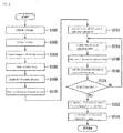
- FIG. 3 is a flowchart showing a flow of a process executed by the track identification device 20.
- the image obtaining unit 22 obtaining an image (an original image) captured by the capturing unit 10 (step S100) .
- the index deriving unit 24 derives an index based on the image obtained in step S100 (step S102).
- the index which is a scale indicating a railway-track-likeness, is an index derived based on, for example, a luminance gradient between a pixel focused on and a neighboring pixel. Also, the index may be derived using a Sobel filter, a Laplacian filter, a Robinson filter, a Canny filter, or the like.
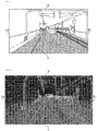
- Fig. 4 is a drawing schematically showing an image captured by the capturing unit 10.
- an upward direction in an image captured by the capturing unit 10 or in an image converted by the image converting unit 26 is defined as an upper end side U, a downward direction as a lower end side L, a right direction as a right end side Ri, and a left direction as a left end side Le.
- Fig. 5 is a drawing showing a result of obtaining a luminance gradient from the image shown in Fig. 4 .
- a railway track is formed of a material such as steel, and as steel has a low light reflectivity compared with stones (ballast) laid down along the railway track, there is a large difference in luminance between pixels corresponding to the railway track portion and pixels in the periphery thereof. As a result, there is a large luminance gradient in a region corresponding to the railway track portion, as shown in Fig. 5 .
- the image converting unit 26 referring to the image conversion information 54, converts the image (original image) obtained in step S100 into a bird' s eye image (step S104) .
- An index in the original image is imparted to a point in the bird' s eye image corresponding to the point from which the index is derived.
- the image conversion information 54 is information indicating a preset conversion rules for converting an original image captured by the capturing unit 10 into a bird's eye image.
- the image conversion information 54 may be a map wherein pixels of the bird's eye image are correlated to pixels of the original image, or may be a function that outputs coordinates in the bird's eye image when coordinates in the original image are input.
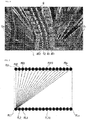
- Fig. 6 is a drawing showing an example of a bird's eye image after a luminance gradient is obtained. A detailed description of Fig. 6 will be given hereafter.
- the initial searching unit 28 refers to the initial area information 52 stored in the storage unit 50 (step S106), and establishes a plurality of lines connecting one arbitrary place in an upper end and one arbitrary place in a lower end of an initial area in the bird's eye image (step S108).
- the initial area information 52 is information indicating a range of a region that is a region preset in the bird's eye image, includes a railway track along which the railway vehicle RV travels, and is positioned on the lower end side L of the bird' s eye image.
- the area information 52 is obtained in advance based on, for example, a position in the railway vehicle RV in which the capturing unit 10 is installed, and a region captured by the capturing unit 10 from the installation position.
- an initial area AR1 including a railway track R1 on the right end side Ri and an initial area AR2 including a railway track R2 on the left end side Le correspond to initial areas.
- Fig. 7 is a drawing showing an aspect wherein a pluraity of lines are established in the initial area AR1.
- a plurality of lines connecting one arbitrary point among points (pixels or pixel groups) PU1 to PUn on the upper end side U of the initial area AR1 and one arbitrary point among points (pixels or pixel groups) PL1 to PLn on the lower end side L of the initial area AR1 are comprehensively established ("n" is an arbitrary positive integer) .
- n is an arbitrary positive integer
- the initial searching unit 28 selects one line in each of the initial areas AR1 and AR2 for which the average index value included in the established line is greater than the index value included in the other lines (step S110) . More specifically, the initial searching unit 28 refers to the image conversion information 54, and selects the line for which the average index value is greatest based on indices corresponding to pixels included in the plurality of lines in the bird' s eye image. Using this process, lines approximating lines wherein pixels corresponding to the railway tracks R1 and R2 in the previously mentioned image of Fig. 6 are aligned are selected.
- the point searching unit 32 searches a predetermined range of the bird's eye image including an upper end (reference position) of the line selected by the initial searching unit 28, identifies a characteristic point whose index is greater than that of other points, and changes the reference point to the characteristic point (step S112) .
- the predetermined range is a line segment region having a predetermined width in a horizontal direction from the reference point identified by the point searching unit 32.
- the predetermined range may also be provided with width in a vertical direction from the reference point identified by the point searching unit 32, forming a rectangular region.
- information (coordinates) regarding the identified characteristic point is stored in the storage unit 50 as the position information 56, to be described hereafter.
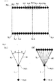
- Fig. 8 is a drawing for describing a process of identifying a characteristic point. A description the same as that for Fig. 7 will be omitted.
- the initial searching unit 28 selects the line connecting the point PL10 and the point PU10 included in the initial area AR1 as the line having the greatest average index value in the process of step S110.
- the point searching unit 32 compares the indices of each of the point PU10 and the points PU7 to PU9 and PU11 to PU13 extending in the horizontal direction from the point PU10, and selects, for example, the pixel having the greatest index as the characteristic point.
- the point PU11 is selected as the characteristic point.
- the secondary searching unit 30 establishes a plurality of lines in a fan-shaped region (search region) in the bird's eye image based on the characteristic point identified by the point searching unit 32 (step S114).
- Fig. 9 is a drawing for describing a process of establishing a plurality of lines based on a characteristic point.
- the secondary searching unit 30 establishes a region of a fan shape (or approximate fan shape) based on the characteristic point PU11 identified by the point searching unit 32, as shown in Fig. 9(A) .
- the fan-shaped region is a region demarcated by the virtual lines VR and VL caused to extend in the upper end side U direction at an angle ⁇ toward the right end side Ri and the left end side Le, with a line L selected by the initial searching unit 28 as a center, and the characteristic point PU11 identified by the point searching unit 32 as an origin.
- the angle ⁇ is a preset angle, and is, for example, an angle that can cover (encompass) a range of a maximum curvature regulated by a railway track standard or the like.
- lengths of the virtual lines VR and VL are preset lengths.
- the secondary searching unit 30 establishes a plurality of lines comprehensively connecting one arbitrary point in an upper end of the fan-shaped region and the characteristic point PU11, as shown in Fig. 9 (B) .
- the secondary searching unit 30 establishes a plurality of points at preset predetermined intervals in the horizontal direction in the upper end of the fan-shaped region, and establishes a plurality of lines comprehensively connecting each of the established points and the characteristic point PU11.
- the secondary searching unit 30 carries out a process the same as the heretofore described process based on the characteristic point identified in the initial area AR2.
- the secondary searching unit 30 selects the line among the plurality of established lines whose average index value is greater than that of the other lines (step S116) . More specifically, the secondary searching unit 30 refers to the image conversion information 54, and selects the line whose average index value is greater than the other lines based on indices corresponding to pixels included in the pluraity of lines in the bird's eye image.
- the point searching unit 32 searches a predetermined range of the bird's eye image including an upper end (reference position) of the line selected by the secondary searching unit 30, identifies a characteristic point whose index is greater than that of other points, and changes the reference point to the characteristic point (step S118).
- the point searching unit 32 determines whether or not an end condition is satisfied (step S120) .
- An end condition is that a distance between two reference points (or characteristic pints) identified with the initial area AR1 and the initial area AR2 as origins is equal to or lower than a threshold, that the process of identifying a reference point carried out by the point searching unit 32 is carried out a predetermined number of times, that a reference point identified by the point searching unit 32 is farther to the upper end side than a predetermined point in the bird's eye image, or the like.
- steps S114 to S118 are repeated.
- the secondary searching unit 30 establishes a plurality of lines in step S114 based on the characteristic point identified in step S118.
- characteristic points are established at predetermined distances toward the upper end side U.
- a characteristic point CPr1 is established based on a characteristic point of the initial area AR1
- a characteristic point CPr2 is identified based on the characteristic point CPr1, ...
- a characteristic point CPr12 is identified.
- a characteristic point CPl1 is established based on a characteristic point of the initial area AR2
- a characteristic point CPl2 is identified based on the characteristic point CPl1, ...
- a characteristic point CPl12 is identified.
- Fig. 10 is a drawing showing details of the point information 56.
- the point information 56 is information indicating coordinates in an image (bird's eye image) of a characteristic point identified by the point searching unit 32.
- the point information 56 is, for example, arranged in accordance with an order of identified characteristic points. Specifically, characteristic points in the point information 56 are arranged in order of a starting point of a line selected in an initial area by the initial searching unit 28, a first characteristic point identified by the point searching unit 32, a second characteristic point identified by the point searching unit 32, ..., and an Nth ("N" is an arbitrary positive integer) characteristic point identified by the point searching unit 32.
- identification information indicating a characteristic point on the right end side, or identification information indicating a characteristic point on the left end side is correlated to a characteristic point identified by the point searching unit 32 in the point information 56.
- the track recognizing unit 34 refers to the point information 56, and identifies a region assumed to be a railwy track by aligning characteristic points identified by the point searching unit 32 (step S122) . Specifically, the track recognizing unit 34 refers to the point information 56, and plots characteristic points identified by the point searching unit 32 in an original image.
- Fig. 11 is a drawing showing an original image in which characteristic points are plotted.
- the track recognizing unit 34 refers to the point information 56, connects a starting point (PL10, PL10#) of a line selected in an initial area and a first characteristic point identified by the point searching unit 32, connects the first characteristic point and a second characteristic point, ..., and connects an Nth - 1 characteristic point and an Nth characteristic point.
- This process is carried out with respect to characteristic points on the left end side and characteristic points on the right end side.
- the regions R1 and R2 assumed to be railway tracks are identified.
- the heretofore described process is such that characteristic point coordinates included in the point information 56 may be output to another functional unit or device unchanged as coordinates corresponding to a bird's eye image, or the characteristic points may be plotted in a bird's eye image.
- the railway track recognition device 20 determines whether or not a suspicious object exists in a vicinity of the railway track, and controls the display unit 12 to display a warning when a suspicious object exists (step S124).
- the determination region identifying unit 36 identifies a determination region.
- the determination region is a region demarcated by the railway tracks R1 and R2 and a region in a vicinity thereof, and is a region in which a suspicious object existing is not allowed.
- Fig. 12 is a drawing for describing an example of a determination region.
- the determination region identifying unit 36 identifies a central line C that is a center of a distance in a horizontal direction between the rail track R1 and the rail track R2 in a predetermined point in an original image, and identifies a length LA of a line extending in a normal direction from the railway track R2 to the central line C. Also, the determination region identifying unit 36 identifies a length LB (a reference length) based on the identified length LA.
- the length LB is a length such that a length XL is added to a left end of the length LA.
- the length XL is a length by which the railway vehicle RV protrudes in a width direction beyond the railway track R2 when the railway vehicle RV travels along the railway track, or a length such that a predetermined length is added to the length by which the railway vehicle RV protrudes.
- the length XL is stored in, for example, the storage unit 50.
- the determination region identifying unit 36 identifies the central line C, which is the center of the interval in the horizontal direction between the railway track R1 and the railway track R2, farther to the upper end side in the original image than the point in which the length LB has been obtained the previous time, and identifies a length LA# of a line extending in the normal direction from the railway track R2 to the central line C. Also, the determination region identifying unit 36 identifies a length LB# (a reference length) based on the identified length LA#. A ratio between the length LA# and the length LB# is the same as a ratio between the length LA and the length LB.
- the determination region identifying unit 36 obtains a reference length farther to the upper end side U than a point in which a reference length has been obtained the previous time as far as a vicinity in which the railway track disappears from the original image.
- the heretofore described process is carried out in the same way on the railway track R1 side. Further, the determination region identifying unit 36 assumes a region demarcated by the virtual line V1, wherein the left ends of the reference lengths are connected in order of being obtained, and the virtual line V2, wherein the right ends of the reference lengths are connected in order of being obtained, to be the determination region.
- the suspicious object monitoring unit 38 determines whether or not an image region coinciding with a suspicious object template exists within the determination region in the original image. For example, a plurality of suspicious object templates are stored in the suspicious object information 58.
- Coinciding not being limited to coinciding perfectly, includes, for example, a resemblance between a form of an image region and a form correlated to a suspicious object template being equal to or greater than a threshold.
- the suspicious object monitoring unit 38 may acquire an image captured by a stereo camera, and determine whether or not a suspicious object exists based on the acquired image and the suspicious object information 58. In this case, a template indicating a three-dimensional form of a suspicious object is included in the suspicious object information 58.
- the output control unit 40 acquires information regarding the image region corresponding to the suspicious object from the suspicious object monitoring unit 38, identifies the acquired image region, and correlates information indicating that a suspicious object exists in the identified image region to the original image. Further, the output control unit 40 controls the display unit 12 to display the processed image on which the heretofore described process has been carried out.
- Fig. 13 is a drawing schematically showing a processed image. For example, when a scene wherein a person is encroaching into a determination region is captured by the capturing unit 10, a processed image including information indicating that a suspicious object exists is displayed on the display unit 12.
- the output control unit 40 may control a warning to be output by a speaker or the like provided in the railway vehicle RV.
- the railway track recognition device 20 can more accurately detect a railway track. Also, when a suspicious object exists within a detected railway track, the railway track recognition device 20 can notify an occupant with information indicating that the suspicious object exists.
- step S110 or step S116 in the heretofore described process when a difference between inclinations of lines obtained by the process of step S110 or step S116 in the heretofore described process is equal to or greater than a reference angle, the angle can be ajdusted.
- the railway track with which the object is assumed to be interfering is complemented based on the other railway track.
- a region approximating the railway track with which the object is interfering can be identified in the image.
- the initial searching unit 28 or the secondary searching unit 30 may adjust so that the distance between the two lines is equal to or less than the threshold. For example, in this case, the initial searching unit 28, for example, brings the two railway tracks closer to each other evenly. By so doing, a railway track can be more accurately detected.
- the secondary searching unit 30 can more accurately identify a reference point by selecting a line whose average index value is greater than the other lines from among a plurality of lines established in a fan-shaped region in a bird's eye image.
- the secondary searching unit 30 can accurately identify a reference point on the upper end side U (that is, a region far from a train) in an original image.
- a predetermined range in a bird's eye image including an upper end of a line selected by the initial searching unit 28 or the secondary searching unit 30 is searched, and a characteristic point whose index is greater than that of other points is identified.
- a pixel whose index is greatest being selected as a characteristic point in this way means that even when a leading end of a line selected based on an average value in step S110 or step S116 differs from a pixel corresponding to an actual railway track, the leading end side of the line can be adjusted to a pixel corresponding to an actual railway track. Also, when an actual railway track is curving, a point corresponding to the railway track is more accurately identified by the leading end of a selected line being adjusted.
- a process of changing of a reference point to a characteristic point may be omitted.
- information regarding the reference point is stored in the point information 56.
- a region assumed to be a railway track is a region wherein reference points are connected.
- a search region is a fan-shaped region centered on a reference point.
- the secondary search unit 30 when the secondary search unit 30 establishes a plurality of lines, the virtual lines VR and VL are established centered on the line L selected by the initial searching unit 28 or the secondary searching unit 30, however it is not limited thereto.
- the secondary searching unit 30 may establish the virtual lines VR and VL taking a line selected by a process before the previous process into consideration.
- Fig. 14 is a drawing for describing an establishment of a virtual line.
- reference points CPrx1 to CPrx3 are identified in that order.
- an angle formed by a line L1 which forms a reference (center) when a virtual line is established, and a line extending in a horizontal direction in a bird' s eye image is an angle ⁇ 1.
- an angle formed by a line L2 which forms a reference when a virtual line is established, and a line extending in the horizontal direction in the bird's eye image is an angle ⁇ 2.
- the railway track recognition device 20 has an initial searching unit 28 that, in an initial area preset in an image, extracts a plurality of line segments connecting one arbitrary point in an upper end of the initial area and one arbitrary point in a lower end, and selects one line segment for which an evaluation value of indices indicating a railway-track-likeness of the line segment derived by the index deriving unit 24 is greater than that of other line segments, the secondary searching unit 30 which, with a point of an upper end of the line segment selected by the initial searching unit 28 as a first reference point, selects a line segment among line segments included in a search region extending toward the top of the image for which the evaluation value of indices is greater than that of other line segments, and repeatedly executes an adoption of the upper end of the selected line segment as the next reference point, and the track recognizing unit 34, which derives a railway track based on results of processes by the initial searching unit 28 and the secondary searching unit 30, whereby a railway track can be more accurately detected
- railway track distribution information 60 is stored in the storage unit 50 of the second embodiment.
- the railway track distribution information 60 is information indicating a region in an image (an original image or a bird' s eye image) in which there is a high possibility of it being assumed that a railway track exists.
- the railway track distribution information 60 is, for example, information obtained experimentally.
- Fig. 15 is a drawing showing an example of an original image in which the railway track distribution information 60 is reflected.
- a region DA is a distribution region in which there is a high possibility of it being assumed that a railway track exists.
- the region DA includes a region DA1, a region DA2, and a region DA3.
- the region DA1 is a distribution region in which there is a possibility of a left-side track, of left and right tracks along which the railway vehicle RV travels, existing
- the region DA2 is a distribution region in which there is a possibility of a right-side track, of the left and right tracks along which the railway vehicle RV travels, existing
- the region DA3 is a distribution region in which there is a possibility of the left-side or the right-side track, or the left-side and the right-side tracks, along which the railway vehicle RV travels existing.
- an initial area AR# is correlated to the railway track distribution information 60.
- the region DA corresponding to a railway track along which the railway vehicle RV in which the railway track recognition device 20 is mounted travels is shown in the example shown in the drawing, but furthermore, a distribution region in which a railway track (for example, a neighboring railway track) differing from the railway track along which the railway vehicle RV in which the railway track recognition device 20 is mounted travels is assumed to exist is included in the railway track distribution information 60.
- the initial searching unit 28 extracts a plurality of lines connecting one arbitrary point in an upper end of the initial area AR# and one arbitrary point in a lower end, selects two lines for which an evaluation value of indices included in the extracted line derived by the index deriving unit 24 is greater than an evaluation value of indices included in other lines, and assumes the two lines to be railway tracks.
- the initial searching unit 28 carries out a process the same as the heretofore described process in an initial area (not shown) corresponding to a railway track differing from the railway track along which the railway vehicle RV in which the railway track recognition device 20 is mounted travels, and assumes the two lines to be a railway track differing from the railway track along which the railway vehicle RV in which the railway track recognition device 20 is mounted travels. Further, when the two assumed railway tracks satisfy a predetermined condition, the initial searching unit 28 specifies that the assumed railway tracks are railway tracks.
- a predetermined condition is that, for example, a distance between left sides (or right sides) of the two railway tracks in a horizontal direction in a bird's eye image of the railway tracks satisfies a set standard (distance range).
- the point searching unit 32 carries out the same process as in the first embodiment on each of the selected lines, establishing reference points corresponding to the railway track along which the railway track RV travels and the railway track differing from that railway track.
- the railway track recognition device 20 in an initial area preset for each railway track in an image, extracts a plurality of lines connecting one arbitrary point in an upper end of the initial area and one arbitrary point in a lower end, selects one line for which an evaluation value of indices included in the extracted line is greater than an evaluation value of indices included in other lines, and carries out the same process as in the first embodiment on each of the selected lines, whereby a plurality of lines can be identified.
- a railway track is identified by referring to past processing results of the railway track recognition device 20.
- a description will be given centered on differences from the first embodiment.
- Fig. 16 is a drawing showing a functional configuration of a railway track recognition device 20A of the third embodiment.
- the railway track recognition device 20A includes an initial searching unit 28A and a storage unit 50A instead of the initial searching unit 28 and the storage unit 50 of the first embodiment.
- Specific track information 62 is stored in the storage unit 50A.
- the identified rail information 62 is information regarding a reference point identified in the past, and information regarding a region assumed to be a railway track identified by the track recognizing unit 34.
- the initial searching unit 28A refers to the specific track information 62, and establishes an initial area.
- Fig. 17 is a drawing for describing a process of establishing an initial area.
- the initial searching unit 28A plots the regions R1 and R2 assumed to be railway tracks on the previous occasion (the regions R1 and R2 assumed to be railway tracks a predetermined time before) and included in the specific track information 62 on a bird' s eye image that is a processing target, and establishes a predetermined region encompassing the plotted region R1 and region R2 as an initial area AR#1.
- the initial searching unit 28A in the initial area AR#1, extracts a plurality of lines connecting one arbitrary point in an upper end of the initial area AR#1 and one arbitrary point in a lower end, and selects one line for which an evaluation value of indices included in the extracted line derived by the index deriving unit 24 is greater than an evaluation value of indices included in other lines. Further, the railway track recognition device 20A identifies a reference point in the same way as in the first embodiment, thereby identifying a region assumed to be a railway track.
- the railway track recognition device 20 determines the initial area AR#1 by referring to the regions R1 and R2 assumed to be railway tracks on the previous occasion and included in the specific track information 62, whereby the same advantages as in the first embodiment can be achieved.
- a railway track can be more accurately detected by having an index deriving unit that derives an index indicating a railway-track-likeness for each pixel or pixel group in an image in which a direction of travel of a railway vehicle is captured, an initial searching unit that, in an initial area preset in the image, extracts a plurality of line segments connecting at least a first point and a second point in an upper end of the initial area and at least a third point and a fourth point in a lower end respectively, and selects one line segment for which an evaluation value of indices derived by the index deriving unit for pixels or pixel groups corresponding to the line segment is greater than an evaluation value of indices derived by the index deriving unit for pixels or pixel groups corresponding to other line segments, a secondary searching unit that, with a point of an upper end of a line segment selected by the initial searching unit as a first reference point, selects a line segment among line segments included in a search region extending toward a
Landscapes
- Engineering & Computer Science (AREA)
- Physics & Mathematics (AREA)
- General Physics & Mathematics (AREA)
- Theoretical Computer Science (AREA)
- Multimedia (AREA)
- Computer Vision & Pattern Recognition (AREA)
- Geometry (AREA)
- Mechanical Engineering (AREA)
- Train Traffic Observation, Control, And Security (AREA)
- Image Analysis (AREA)
- Electric Propulsion And Braking For Vehicles (AREA)
Abstract
Description
- Embodiments described herein relate to a railway track recognition apparatus, a program, and a railway track recognition method.
- A device that detects a railway track from an image with an object of inspecting a railway track or detecting an obstacle existing within a railway track is already known. This kind of device, for example, detects a railway track by matching a captured image and a template prepared in advance, or detects a railway track, on which a vehicle is travelling, using an image captured by a stereo camera. However, there is a case in which the existing device cannot accurately detect a railway track.
-
- PATENT LITERATURE 1:
JP-A-2016-91506 - PATENT LITERATURE 2:
JP-A-2000-32601 - An object of the invention is to provide a railway track recognition apparatus, a program, and a railway track recognition method such that a railway track can be more accurately detected.
- A railway track recognition apparatus according to an embodiment has an index deriving unit, an initial searching unit, a secondary searching unit, and a railway track recognizing unit. The index deriving unit derives an index indicating a railway-track-likeness for each pixel or pixel group of a captured image of a train vehicle running direction. The initial searching unit, in a preset initial area for the captured image, extracts a plurality of line segments connecting at least a first point and a second point on an upper end of the initial area and at least a third point and a fourth point on a lower end respectively, and selects one line segment for which an evaluation value of indices derived by the index deriving unit for pixels or pixel groups corresponding to the line segment is greater than an evaluation value of indices derived by the index deriving unit for pixels or pixel groups corresponding to other line segments. The secondary searching unit, with a position of an upper end of a line segment selected by the initial searching unit as a first reference position, selects a line segment among line segments included in a search region extending toward a top of the image for which an evaluation value of indices is greater than an evaluation value of indices of other line segments, and repeatedly executes an adoption of an upper end of the selected line segment as a next reference position. The railway track recognizing unit recognizes a railway track based on results of processes by the initial searching unit and the secondary searching unit.
-
-
Fig. 1 is a configuration drawing of avehicle system 1 including a railwaytrack recognition device 20. -
Fig. 2 is a functional configuration drawing of the railwaytrack recognition device 20. -
Fig. 3 is a flowchart showing a flow of a process executed by the railwaytrack recognition device 20. -
Fig. 4 is a drawing schematically showing an image captured by animage capturing unit 10. -
Fig. 5 is a drawing showing a result of obtaining a luminance gradient from the image shown inFig. 4 . -
Fig. 6 is a drawing showing an example of a bird's eye image after a luminance gradient is obtained. -
Fig. 7 is a drawing showing an aspect wherein a plurality of lines are established in an initial area AR1. -
Fig. 8 is a drawing for describing a process of identifying a characteristic point. -
Fig. 9 is a drawing for describing a process of establishing a plurality of lines based on a characteristic point. -
Fig. 10 is a drawing showing details ofpoint information 56. -
Fig. 11 is a drawing showing an original image in which characteristic points are plotted. -
Fig. 12 is a drawing for describing an example of a determination area. -
Fig. 13 is a drawing schematically showing a processed image. -
Fig. 14 is a drawing for describing an establishment of a virtual line. -
Fig. 15 is a drawing showing an example of an original image in which railwaytrack distribution information 60 is reflected. -
Fig. 16 is a drawing showing a functional configuration of a railwaytrack recognition device 20A of a third embodiment. -
Fig. 17 is a drawing for describing a process of establishing an initial area. - Hereafter, a railway track recognition device, a program, and a railway track recognition method of an embodiment will be described, referring to the drawings.
-
Fig. 1 is a configuration drawing of avehicle system 1 including a railwaytrack recognition device 20. Thevehicle system 1 is a system mounted in a railway vehicle RV that travels on a railway track R. Thevehicle system 1 includes, for example, animage capturing unit 10, adisplay unit 12, and the railwaytrack recognition device 20. Theimage capturing unit 10 is provided in a driver's seat or the like of the railway vehicle RV, and captures images in a travelling direction of the railway vehicle RV (the direction of the arrow inFig. 1 ) . The capturingunit 10, for example, captures images in a direction in which the railway track R extends, as shown inFig. 1 . Thedisplay unit 12 displays various kinds of image. -
Fig. 2 is a functional configuration drawing of the railwaytrack recognition device 20. The railwaytrack recognition device 20 includes, for example, animage obtaining unit 22, anindex deriving unit 24, animage converting unit 26, aninitial searching unit 28, asecondary searching unit 30, apoint searching unit 32, atrack recognizing unit 34, a determinationregion identifying unit 36, a suspiciousobject monitoring unit 38, anoutput control unit 40, and astorage unit 50. Part or all of theimage obtaining unit 22, theindex deriving unit 24, theimage converting unit 26, theinitial searching unit 28, thesecondary searching unit 30, thepoint searching unit 32, thetrack recognizing unit 34, the determinationregion identifying unit 36, the suspiciousobject monitoring unit 38, and theoutput control unit 40 are realized by, for example, a processor such as a CPU (central processing unit) executing a program stored in thestorage unit 50. Also, part or all of these functional units may be realized by hardware such as an LSI (large scale integration), an ASIC (application specific integrated circuit), or an FPGA (field-programmable gate array), and have a circuit configuration for realizing functions of the functional units, or may be realized by collaboration between software and hardware. The program may be stored in advance in a storage device such as an HDD (hard disk drive) or a flash memory, or may be stored in a removable storage medium such as a DVD or a CD-ROM, and installed in a storage device by the storage medium being mounted in a drive device. - The
storage unit 50 is realized by, for example, a non-volatile storage medium such as a ROM (read only memory), a flash memory, an HDD (hard disk drive), or an SD card, and a volatile storage medium such as a RAM (random access memory) or a register. Thestorage unit 50 stores the program executed by the processor, andinitial area information 52,image conversion information 54,point information 56,suspicious object information 58, and the like, to be described hereafter. - The
image obtaining unit 22 obtains an image captured by theimage capturing unit 10. The captured image is, for example, a color image. Theindex deriving unit 24, for example, converts a color image into a grayscale image or a binarized image, and derives an index indicating a railway-track-likeness for each pixel of the converted image. As a result, an index image composed of a pixel and an index (corresponding to the pixel is obtained. Also, instead of this, theindex deriving unit 24 may derive an index indicating a railway-track-likeness for each pixel group wherein a predetermined number of pixels are grouped. Theimage converting unit 26 converts an index image generated by theindex deriving unit 24 into a bird's eye image seen from air. - In an initial area preset for a bird' s eye image converted from an index image, the
initial searching unit 28 comprehensively extracts a plurality of line segments connecting one arbitrary point on an upper end of the initial area and one arbitrary point on a lower end. For example, theinitial searching unit 28 extracts a plurality of line segments connecting at least a first point and a second point on the upper end of the initial area and at least a third point and a fourth point on the lower end respectively, and selects one line segment for which an evaluation value of indices derived by theindex deriving unit 24 for pixels or pixel groups corresponding to the line segment is greater than an evaluation value of indices derived by theindex deriving unit 24 for pixels or pixel groups corresponding to other line segments. A "line" is a region in which pixels, or pixel groups composed of pixels, extend in a predetermined direction. Theinitial searching unit 28 selects one line segment for which an evaluation value of indices derived by theindex deriving unit 24 in the line is greater than that of other line segments. An evaluation value is a value indicating a railway-track-likeness. For example, the higher the evaluation value, the higher the probability that a line segment corresponding to the evaluation value is a railway track. The evaluation value may be an average value of indices, or may be a value such that indices have been processed using a predetermined evaluation function. In the following description, it will be assumed as an example that the evaluation value is the average value of indices. - The
secondary searching unit 30, with a point of an upper end of a line segment selected by theinitial searching unit 28 as a first reference point, selects a line segment among line segments included in a search region extending toward a top of the image for which the evaluation value of indices is greater than the evaluation value of indices of other line segments, and repeatedly executes an adoption of an upper end of the selected line segment as the next reference point. A search region extending toward the top of the image is, for example, a region forming a fan-shaped form that needs a reference point (or a characteristic point) . Also, the search region may be a region demarcated by a first virtual line (for example, VR inFig. 9 ) extending a predetermined distance upward in the image from the reference point and a second virtual line (for example, VL inFig. 9 ) extending a predetermined distance upward in the image from the reference point, which form a predetermined angle, and a third virtual line connecting an upper end of the first virtual line and an upper end of the second virtual line. The third virtual line may be, for example, a straight line, or may be a curved line. - The
point searching unit 32 searches a predetermined range including the upper end of a line segment selected by theinitial searching unit 28 or thesecondary searching unit 30, identifies a characteristic point whose index is greater than that of other portions, and changes the reference point to the characteristic point. - The
track recognizing unit 34 recognizes a railway track based on results of processes by theinitial searching unit 28 and thesecondary searching unit 30. Specifically, therail recognizing unit 34 recognizes a line in which characteristic points identified by thepoint searching unit 32 are aligned as a railway track. - The determination
region identifying unit 36 identifies a determination region (details will be described later) in an image based on information regarding a railway track recognized by thetrack recognizing unit 34. The suspiciousobject monitoring unit 38 determines whether or not a suspicious object exists in the determination region. When it is determined by the suspiciousobject monitoring unit 38 that a suspicious object exists in the determination region, theoutput control unit 40 correlates information indicating that a suspicious object exists to an image captured by the capturingunit 10, and controls thedisplay unit 12 to display the image. - Hereafter, a process of each functional unit heretofore described will be described while referring to a flowchart.
Fig. 3 is a flowchart showing a flow of a process executed by thetrack identification device 20. - Firstly, the
image obtaining unit 22 obtaining an image (an original image) captured by the capturing unit 10 (step S100) . Next, theindex deriving unit 24 derives an index based on the image obtained in step S100 (step S102). The index, which is a scale indicating a railway-track-likeness, is an index derived based on, for example, a luminance gradient between a pixel focused on and a neighboring pixel. Also, the index may be derived using a Sobel filter, a Laplacian filter, a Robinson filter, a Canny filter, or the like. -
Fig. 4 is a drawing schematically showing an image captured by the capturingunit 10. In the following description, an upward direction in an image captured by the capturingunit 10 or in an image converted by theimage converting unit 26 is defined as an upper end side U, a downward direction as a lower end side L, a right direction as a right end side Ri, and a left direction as a left end side Le. -
Fig. 5 is a drawing showing a result of obtaining a luminance gradient from the image shown inFig. 4 . A railway track is formed of a material such as steel, and as steel has a low light reflectivity compared with stones (ballast) laid down along the railway track, there is a large difference in luminance between pixels corresponding to the railway track portion and pixels in the periphery thereof. As a result, there is a large luminance gradient in a region corresponding to the railway track portion, as shown inFig. 5 . - Next, the
image converting unit 26, referring to theimage conversion information 54, converts the image (original image) obtained in step S100 into a bird' s eye image (step S104) . An index in the original image is imparted to a point in the bird' s eye image corresponding to the point from which the index is derived. Theimage conversion information 54 is information indicating a preset conversion rules for converting an original image captured by the capturingunit 10 into a bird's eye image. Theimage conversion information 54 may be a map wherein pixels of the bird's eye image are correlated to pixels of the original image, or may be a function that outputs coordinates in the bird's eye image when coordinates in the original image are input.Fig. 6 is a drawing showing an example of a bird's eye image after a luminance gradient is obtained. A detailed description ofFig. 6 will be given hereafter. - Next, the
initial searching unit 28 refers to theinitial area information 52 stored in the storage unit 50 (step S106), and establishes a plurality of lines connecting one arbitrary place in an upper end and one arbitrary place in a lower end of an initial area in the bird's eye image (step S108). Theinitial area information 52 is information indicating a range of a region that is a region preset in the bird's eye image, includes a railway track along which the railway vehicle RV travels, and is positioned on the lower end side L of the bird' s eye image. Thearea information 52 is obtained in advance based on, for example, a position in the railway vehicle RV in which thecapturing unit 10 is installed, and a region captured by the capturingunit 10 from the installation position. In the previously mentioned example ofFig. 6 , an initial area AR1 including a railway track R1 on the right end side Ri and an initial area AR2 including a railway track R2 on the left end side Le correspond to initial areas. -
Fig. 7 is a drawing showing an aspect wherein a pluraity of lines are established in the initial area AR1. InFig. 7 , a plurality of lines connecting one arbitrary point among points (pixels or pixel groups) PU1 to PUn on the upper end side U of the initial area AR1 and one arbitrary point among points (pixels or pixel groups) PL1 to PLn on the lower end side L of the initial area AR1 are comprehensively established ("n" is an arbitrary positive integer) . In the example shown, a case in which the point PL1 is connected to each of PU1 to PUn is shown, but in the process of step S108, lines comprehensively connecting each of the points PL1 to PLn and each of the points PU1 to PUn are established. Also, the same process is carried out in the initial area AR2 as well. - Next, the
initial searching unit 28 selects one line in each of the initial areas AR1 and AR2 for which the average index value included in the established line is greater than the index value included in the other lines (step S110) . More specifically, theinitial searching unit 28 refers to theimage conversion information 54, and selects the line for which the average index value is greatest based on indices corresponding to pixels included in the plurality of lines in the bird' s eye image. Using this process, lines approximating lines wherein pixels corresponding to the railway tracks R1 and R2 in the previously mentioned image ofFig. 6 are aligned are selected. - Next, the
point searching unit 32 searches a predetermined range of the bird's eye image including an upper end (reference position) of the line selected by theinitial searching unit 28, identifies a characteristic point whose index is greater than that of other points, and changes the reference point to the characteristic point (step S112) . The predetermined range is a line segment region having a predetermined width in a horizontal direction from the reference point identified by thepoint searching unit 32. The predetermined range may also be provided with width in a vertical direction from the reference point identified by thepoint searching unit 32, forming a rectangular region. Also, information (coordinates) regarding the identified characteristic point is stored in thestorage unit 50 as theposition information 56, to be described hereafter. -
Fig. 8 is a drawing for describing a process of identifying a characteristic point. A description the same as that forFig. 7 will be omitted. For example, it is assumed that theinitial searching unit 28 selects the line connecting the point PL10 and the point PU10 included in the initial area AR1 as the line having the greatest average index value in the process of step S110. In this case, thepoint searching unit 32 compares the indices of each of the point PU10 and the points PU7 to PU9 and PU11 to PU13 extending in the horizontal direction from the point PU10, and selects, for example, the pixel having the greatest index as the characteristic point. In the embodiment, it is assumed that the point PU11 is selected as the characteristic point. - Next, the
secondary searching unit 30 establishes a plurality of lines in a fan-shaped region (search region) in the bird's eye image based on the characteristic point identified by the point searching unit 32 (step S114).Fig. 9 is a drawing for describing a process of establishing a plurality of lines based on a characteristic point. For example, thesecondary searching unit 30 establishes a region of a fan shape (or approximate fan shape) based on the characteristic point PU11 identified by thepoint searching unit 32, as shown inFig. 9(A) . The fan-shaped region is a region demarcated by the virtual lines VR and VL caused to extend in the upper end side U direction at an angle θ toward the right end side Ri and the left end side Le, with a line L selected by theinitial searching unit 28 as a center, and the characteristic point PU11 identified by thepoint searching unit 32 as an origin. - The angle θ is a preset angle, and is, for example, an angle that can cover (encompass) a range of a maximum curvature regulated by a railway track standard or the like. Also, lengths of the virtual lines VR and VL are preset lengths. Further, the
secondary searching unit 30 establishes a plurality of lines comprehensively connecting one arbitrary point in an upper end of the fan-shaped region and the characteristic point PU11, as shown inFig. 9 (B) . For example, thesecondary searching unit 30 establishes a plurality of points at preset predetermined intervals in the horizontal direction in the upper end of the fan-shaped region, and establishes a plurality of lines comprehensively connecting each of the established points and the characteristic point PU11. Thesecondary searching unit 30 carries out a process the same as the heretofore described process based on the characteristic point identified in the initial area AR2. - Next, the
secondary searching unit 30 selects the line among the plurality of established lines whose average index value is greater than that of the other lines (step S116) . More specifically, thesecondary searching unit 30 refers to theimage conversion information 54, and selects the line whose average index value is greater than the other lines based on indices corresponding to pixels included in the pluraity of lines in the bird's eye image. - Next, the
point searching unit 32 searches a predetermined range of the bird's eye image including an upper end (reference position) of the line selected by thesecondary searching unit 30, identifies a characteristic point whose index is greater than that of other points, and changes the reference point to the characteristic point (step S118). - Next, the
point searching unit 32 determines whether or not an end condition is satisfied (step S120) . An end condition is that a distance between two reference points (or characteristic pints) identified with the initial area AR1 and the initial area AR2 as origins is equal to or lower than a threshold, that the process of identifying a reference point carried out by thepoint searching unit 32 is carried out a predetermined number of times, that a reference point identified by thepoint searching unit 32 is farther to the upper end side than a predetermined point in the bird's eye image, or the like. - When no end condition is satisfied, the process of steps S114 to S118 is repeated. In this case, the
secondary searching unit 30 establishes a plurality of lines in step S114 based on the characteristic point identified in step S118. By the process of steps S114 to S118 being repeated in this way, characteristic points are established at predetermined distances toward the upper end side U. - The previously mentioned
Fig. 6 will be described. As shown in the drawing, a characteristic point CPr1 is established based on a characteristic point of the initial area AR1, a characteristic point CPr2 is identified based on the characteristic point CPr1, ..., and a characteristic point CPr12 is identified. In the same way, a characteristic point CPl1 is established based on a characteristic point of the initial area AR2, a characteristic point CPl2 is identified based on the characteristic point CPl1, ..., and a characteristic point CPl12 is identified. - Also, information (coordinates) regarding an established characteristic point is stored in the
storage unit 50 as thepoint information 56.Fig. 10 is a drawing showing details of thepoint information 56. Thepoint information 56 is information indicating coordinates in an image (bird's eye image) of a characteristic point identified by thepoint searching unit 32. Thepoint information 56 is, for example, arranged in accordance with an order of identified characteristic points. Specifically, characteristic points in thepoint information 56 are arranged in order of a starting point of a line selected in an initial area by theinitial searching unit 28, a first characteristic point identified by thepoint searching unit 32, a second characteristic point identified by thepoint searching unit 32, ..., and an Nth ("N" is an arbitrary positive integer) characteristic point identified by thepoint searching unit 32. Also, identification information indicating a characteristic point on the right end side, or identification information indicating a characteristic point on the left end side, is correlated to a characteristic point identified by thepoint searching unit 32 in thepoint information 56. - When an end condition is satisfied, the
track recognizing unit 34 refers to thepoint information 56, and identifies a region assumed to be a railwy track by aligning characteristic points identified by the point searching unit 32 (step S122) . Specifically, thetrack recognizing unit 34 refers to thepoint information 56, and plots characteristic points identified by thepoint searching unit 32 in an original image.Fig. 11 is a drawing showing an original image in which characteristic points are plotted. For example, as shown in the drawing, characteristic points (CP10, CPr0 (= PUr10)) identified by thepoint searching unit 32, and first characteristic points (CP11, CPr1) to Nth (for example, CP12, CPr2 to CP16, CPr6, and the like) characteristic points identified by thepoint searching unit 32, are plotted. - Furthermore, the
track recognizing unit 34 refers to thepoint information 56, connects a starting point (PL10, PL10#) of a line selected in an initial area and a first characteristic point identified by thepoint searching unit 32, connects the first characteristic point and a second characteristic point, ..., and connects an Nth - 1 characteristic point and an Nth characteristic point. This process is carried out with respect to characteristic points on the left end side and characteristic points on the right end side. By the process being carried out in this way, the regions R1 and R2 assumed to be railway tracks are identified. The heretofore described process is such that characteristic point coordinates included in thepoint information 56 may be output to another functional unit or device unchanged as coordinates corresponding to a bird's eye image, or the characteristic points may be plotted in a bird's eye image. - Next, the railway
track recognition device 20 determines whether or not a suspicious object exists in a vicinity of the railway track, and controls thedisplay unit 12 to display a warning when a suspicious object exists (step S124). For example, firstly, the determinationregion identifying unit 36 identifies a determination region. The determination region is a region demarcated by the railway tracks R1 and R2 and a region in a vicinity thereof, and is a region in which a suspicious object existing is not allowed. -
Fig. 12 is a drawing for describing an example of a determination region. The determinationregion identifying unit 36, for example, identifies a central line C that is a center of a distance in a horizontal direction between the rail track R1 and the rail track R2 in a predetermined point in an original image, and identifies a length LA of a line extending in a normal direction from the railway track R2 to the central line C. Also, the determinationregion identifying unit 36 identifies a length LB (a reference length) based on the identified length LA. The length LB is a length such that a length XL is added to a left end of the length LA. The length XL is a length by which the railway vehicle RV protrudes in a width direction beyond the railway track R2 when the railway vehicle RV travels along the railway track, or a length such that a predetermined length is added to the length by which the railway vehicle RV protrudes. The length XL is stored in, for example, thestorage unit 50. - Furthermore, the determination
region identifying unit 36, for example, identifies the central line C, which is the center of the interval in the horizontal direction between the railway track R1 and the railway track R2, farther to the upper end side in the original image than the point in which the length LB has been obtained the previous time, and identifies a length LA# of a line extending in the normal direction from the railway track R2 to the central line C. Also, the determinationregion identifying unit 36 identifies a length LB# (a reference length) based on the identified length LA#. A ratio between the length LA# and the length LB# is the same as a ratio between the length LA and the length LB. The determinationregion identifying unit 36 obtains a reference length farther to the upper end side U than a point in which a reference length has been obtained the previous time as far as a vicinity in which the railway track disappears from the original image. The heretofore described process is carried out in the same way on the railway track R1 side. Further, the determinationregion identifying unit 36 assumes a region demarcated by the virtual line V1, wherein the left ends of the reference lengths are connected in order of being obtained, and the virtual line V2, wherein the right ends of the reference lengths are connected in order of being obtained, to be the determination region. - Also, the suspicious
object monitoring unit 38, for example, referring to thesuspicious object information 58 and using an index derived by theindex deriving unit 24, determines whether or not an image region coinciding with a suspicious object template exists within the determination region in the original image. For example, a plurality of suspicious object templates are stored in thesuspicious object information 58. Coinciding, not being limited to coinciding perfectly, includes, for example, a resemblance between a form of an image region and a form correlated to a suspicious object template being equal to or greater than a threshold. The suspiciousobject monitoring unit 38 may acquire an image captured by a stereo camera, and determine whether or not a suspicious object exists based on the acquired image and thesuspicious object information 58. In this case, a template indicating a three-dimensional form of a suspicious object is included in thesuspicious object information 58. - When it is determined by the suspicious
object monitoring unit 38 that a suspicious object exists within the determination region, theoutput control unit 40 acquires information regarding the image region corresponding to the suspicious object from the suspiciousobject monitoring unit 38, identifies the acquired image region, and correlates information indicating that a suspicious object exists in the identified image region to the original image. Further, theoutput control unit 40 controls thedisplay unit 12 to display the processed image on which the heretofore described process has been carried out.Fig. 13 is a drawing schematically showing a processed image. For example, when a scene wherein a person is encroaching into a determination region is captured by the capturingunit 10, a processed image including information indicating that a suspicious object exists is displayed on thedisplay unit 12. Theoutput control unit 40 may control a warning to be output by a speaker or the like provided in the railway vehicle RV. By so doing, an occupant of the railway vehicle RV can recognize that a suspicious object exists in the direction of travel of the railway vehicle RV. Further, the occupant can control the railway vehicle RV taking the existence of the suspicious object into consideration. - According to the heretofore described process, the railway
track recognition device 20 can more accurately detect a railway track. Also, when a suspicious object exists within a detected railway track, the railwaytrack recognition device 20 can notify an occupant with information indicating that the suspicious object exists. - Also, when a difference between inclinations of lines obtained by the process of step S110 or step S116 in the heretofore described process is equal to or greater than a reference angle, the angle can be ajdusted. By so doing, even when an object interferes with one railway track (the railway track on the right side or the left side), and a line differing from the railway track is selected, the railway track with which the object is assumed to be interfering is complemented based on the other railway track. As a result, a region approximating the railway track with which the object is interfering can be identified in the image.
- Also, when a distance between two selected lines exceeds a threshold preset based on a distance between railway tracks in the process described above, the
initial searching unit 28 or thesecondary searching unit 30 may adjust so that the distance between the two lines is equal to or less than the threshold. For example, in this case, theinitial searching unit 28, for example, brings the two railway tracks closer to each other evenly. By so doing, a railway track can be more accurately detected. - Also, in the process described above, the
secondary searching unit 30 can more accurately identify a reference point by selecting a line whose average index value is greater than the other lines from among a plurality of lines established in a fan-shaped region in a bird's eye image. In particular, thesecondary searching unit 30 can accurately identify a reference point on the upper end side U (that is, a region far from a train) in an original image. - Also, in the process described above, a predetermined range in a bird's eye image including an upper end of a line selected by the
initial searching unit 28 or thesecondary searching unit 30 is searched, and a characteristic point whose index is greater than that of other points is identified. A pixel whose index is greatest being selected as a characteristic point in this way means that even when a leading end of a line selected based on an average value in step S110 or step S116 differs from a pixel corresponding to an actual railway track, the leading end side of the line can be adjusted to a pixel corresponding to an actual railway track. Also, when an actual railway track is curving, a point corresponding to the railway track is more accurately identified by the leading end of a selected line being adjusted. - A process of changing of a reference point to a characteristic point may be omitted. In this case, information regarding the reference point is stored in the
point information 56. Further, a region assumed to be a railway track is a region wherein reference points are connected. Also, in this case, a search region is a fan-shaped region centered on a reference point. - Also, in the process described above, when the
secondary search unit 30 establishes a plurality of lines, the virtual lines VR and VL are established centered on the line L selected by theinitial searching unit 28 or thesecondary searching unit 30, however it is not limited thereto. For example, thesecondary searching unit 30 may establish the virtual lines VR and VL taking a line selected by a process before the previous process into consideration. -
Fig. 14 is a drawing for describing an establishment of a virtual line. For example, it is assumed that reference points CPrx1 to CPrx3 are identified in that order. Also, it is assumed that when a plurality of lines are established based on the reference point CPrx1, an angle formed by a line L1, which forms a reference (center) when a virtual line is established, and a line extending in a horizontal direction in a bird' s eye image is an angle θ1. It is assumed that when a plurality of lines are established based on the reference point CPrx2, an angle formed by a line L2, which forms a reference when a virtual line is established, and a line extending in the horizontal direction in the bird's eye image is an angle θ2. Also, it is assumed that when a plurality of lines are established based on the reference point CPrx3, an angle formed by a line L3, which forms a reference when a virtual line is established, and a line extending in the horizontal direction in the bird' s eye image is an angle θ3. In this case, the angle 3 is obtained based on an Equation (1). By the angle θ3 being obtained in this way, a plurality of lines reflecting a curvature of a rail can be established, and a railway track can be more reliably included in a search region. The angle θ in the drawing is the angle θ that can cover a range of a maximum curvature regulated by a railway track standard or the like described usingFig. 9 .
- According to the heretofore described first embodiment, the railway
track recognition device 20 has aninitial searching unit 28 that, in an initial area preset in an image, extracts a plurality of line segments connecting one arbitrary point in an upper end of the initial area and one arbitrary point in a lower end, and selects one line segment for which an evaluation value of indices indicating a railway-track-likeness of the line segment derived by theindex deriving unit 24 is greater than that of other line segments, thesecondary searching unit 30 which, with a point of an upper end of the line segment selected by theinitial searching unit 28 as a first reference point, selects a line segment among line segments included in a search region extending toward the top of the image for which the evaluation value of indices is greater than that of other line segments, and repeatedly executes an adoption of the upper end of the selected line segment as the next reference point, and thetrack recognizing unit 34, which derives a railway track based on results of processes by theinitial searching unit 28 and thesecondary searching unit 30, whereby a railway track can be more accurately detected. - In a second embodiment, a description has been given assuming that a single railway track is identified. As opposed to this, multiple railway tracks are identified in a second embodiment. Hereafter, a description will be given centered on differences from the first embodiment.
- For example, railway
track distribution information 60 is stored in thestorage unit 50 of the second embodiment. The railwaytrack distribution information 60 is information indicating a region in an image (an original image or a bird' s eye image) in which there is a high possibility of it being assumed that a railway track exists. The railwaytrack distribution information 60 is, for example, information obtained experimentally.Fig. 15 is a drawing showing an example of an original image in which the railwaytrack distribution information 60 is reflected. In the drawing, a region DA is a distribution region in which there is a high possibility of it being assumed that a railway track exists. The region DA includes a region DA1, a region DA2, and a region DA3. The region DA1 is a distribution region in which there is a possibility of a left-side track, of left and right tracks along which the railway vehicle RV travels, existing, and the region DA2 is a distribution region in which there is a possibility of a right-side track, of the left and right tracks along which the railway vehicle RV travels, existing. Also, the region DA3 is a distribution region in which there is a possibility of the left-side or the right-side track, or the left-side and the right-side tracks, along which the railway vehicle RV travels existing. - Also, an initial area AR# is correlated to the railway
track distribution information 60. The region DA corresponding to a railway track along which the railway vehicle RV in which the railwaytrack recognition device 20 is mounted travels is shown in the example shown in the drawing, but furthermore, a distribution region in which a railway track (for example, a neighboring railway track) differing from the railway track along which the railway vehicle RV in which the railwaytrack recognition device 20 is mounted travels is assumed to exist is included in the railwaytrack distribution information 60. - In the initial area AR#, the
initial searching unit 28 extracts a plurality of lines connecting one arbitrary point in an upper end of the initial area AR# and one arbitrary point in a lower end, selects two lines for which an evaluation value of indices included in the extracted line derived by theindex deriving unit 24 is greater than an evaluation value of indices included in other lines, and assumes the two lines to be railway tracks. Also, theinitial searching unit 28 carries out a process the same as the heretofore described process in an initial area (not shown) corresponding to a railway track differing from the railway track along which the railway vehicle RV in which the railwaytrack recognition device 20 is mounted travels, and assumes the two lines to be a railway track differing from the railway track along which the railway vehicle RV in which the railwaytrack recognition device 20 is mounted travels. Further, when the two assumed railway tracks satisfy a predetermined condition, theinitial searching unit 28 specifies that the assumed railway tracks are railway tracks. A predetermined condition is that, for example, a distance between left sides (or right sides) of the two railway tracks in a horizontal direction in a bird's eye image of the railway tracks satisfies a set standard (distance range). - In a subsequent process, the
point searching unit 32 carries out the same process as in the first embodiment on each of the selected lines, establishing reference points corresponding to the railway track along which the railway track RV travels and the railway track differing from that railway track. - According to the second embodiment described above, the railway
track recognition device 20, in an initial area preset for each railway track in an image, extracts a plurality of lines connecting one arbitrary point in an upper end of the initial area and one arbitrary point in a lower end, selects one line for which an evaluation value of indices included in the extracted line is greater than an evaluation value of indices included in other lines, and carries out the same process as in the first embodiment on each of the selected lines, whereby a plurality of lines can be identified. - In a third embodiment, a railway track is identified by referring to past processing results of the railway
track recognition device 20. Hereafter, a description will be given centered on differences from the first embodiment. -
Fig. 16 is a drawing showing a functional configuration of a railwaytrack recognition device 20A of the third embodiment. The railwaytrack recognition device 20A includes an initial searching unit 28A and astorage unit 50A instead of theinitial searching unit 28 and thestorage unit 50 of the first embodiment.Specific track information 62 is stored in thestorage unit 50A. The identifiedrail information 62 is information regarding a reference point identified in the past, and information regarding a region assumed to be a railway track identified by thetrack recognizing unit 34. - The initial searching unit 28A refers to the
specific track information 62, and establishes an initial area.Fig. 17 is a drawing for describing a process of establishing an initial area. The initial searching unit 28A plots the regions R1 and R2 assumed to be railway tracks on the previous occasion (the regions R1 and R2 assumed to be railway tracks a predetermined time before) and included in thespecific track information 62 on a bird' s eye image that is a processing target, and establishes a predetermined region encompassing the plotted region R1 and region R2 as an initialarea AR# 1. The initial searching unit 28A, in the initialarea AR# 1, extracts a plurality of lines connecting one arbitrary point in an upper end of the initialarea AR# 1 and one arbitrary point in a lower end, and selects one line for which an evaluation value of indices included in the extracted line derived by theindex deriving unit 24 is greater than an evaluation value of indices included in other lines. Further, the railwaytrack recognition device 20A identifies a reference point in the same way as in the first embodiment, thereby identifying a region assumed to be a railway track. - According to the heretofore described third embodiment, the railway
track recognition device 20 determines the initialarea AR# 1 by referring to the regions R1 and R2 assumed to be railway tracks on the previous occasion and included in thespecific track information 62, whereby the same advantages as in the first embodiment can be achieved. - According to at least one of the embodiments described above, a railway track can be more accurately detected by having an index deriving unit that derives an index indicating a railway-track-likeness for each pixel or pixel group in an image in which a direction of travel of a railway vehicle is captured, an initial searching unit that, in an initial area preset in the image, extracts a plurality of line segments connecting at least a first point and a second point in an upper end of the initial area and at least a third point and a fourth point in a lower end respectively, and selects one line segment for which an evaluation value of indices derived by the index deriving unit for pixels or pixel groups corresponding to the line segment is greater than an evaluation value of indices derived by the index deriving unit for pixels or pixel groups corresponding to other line segments, a secondary searching unit that, with a point of an upper end of a line segment selected by the initial searching unit as a first reference point, selects a line segment among line segments included in a search region extending toward a top of the image for which the evaluation value of indices is greater than the evaluation value of indices of other line segments, and repeatedly executes an adoption of the upper end of the selected line segment as the next reference point, and a railway track deriving unit that derives a railway track based on results of processes by the initial searching unit and the secondary searching unit.
- Although some embodiments of the invention have been described, these embodiments are presented as examples, and are not intended to limit the scope of the invention. The embodiments can be implemented in various other forms, and various omissions, replacements, and changes can be carried out without departing from the gist of the invention. The embodiments and modifications thereof are included in the scope and gist of the invention, and in the same way, are included in the invention described in the patent claims and an equivalent scope thereof.
Claims (7)
- A railway track recognition device, comprising:an index deriving unit which derives an index indicating railway-track-likeness for each pixel or pixel group of a captured image of a train vehicle running direction;an initial searching unit which, in an initial area preset in the image, extracts a plurality of line segments connecting at least a first point and a second point in an upper end of the initial area and at least a third point and a fourth point in a lower end respectively, and selects one line segment for which an evaluation value of indices derived by the index deriving unit for pixels or pixel groups corresponding to the line segment is greater than an evaluation value of indices derived by the index deriving unit for pixels or pixel groups corresponding to other line segments;a secondary searching unit that, with a point of an upper end of a line segment selected by the initial searching unit as a first reference point, selects a line segment among line segments included in a search region extending toward a top of the image for which an evaluation value of indices is greater than an evaluation value of indices of other line segments, and repeatedly executes an adoption of an upper end of the selected line segment as a next reference point; anda track recognizing unit that recognizes a railway track based on results of processes by the initial searching unit and the secondary searching unit.
- The railway track recognition device according to claim 1, wherein the search region is a region that has a reference point as a center point and extends in a fan form toward the top of the image, or a region demarcated by a first virtual line extending a predetermined distance upward in the image from the reference point and a second virtual line extending a predetermined distance upward in the image from the reference point, which form a predetermined angle, and a third virtual line connecting an upper end of the first virtual line and an upper end of the second virtual line.
- The railway track recognition device according to claim 1 or claim 2, further comprising
a point searching unit which searches a predetermined range including an upper end of a line segment selected by the initial searching unit or the secondary searching unit, identifies a characteristic point whose index is greater than that of other points, and changes the reference point to the characteristic point. - The railway track recognition device according to claim 3, wherein
the predetermined range is a line segment region extending in a horizontal direction in the image with the upper end as a center, or a rectangular region that also has a width in a vertical direction in the image. - The railway track recognition device according to any one of claims 1 to 4, further comprising
a converting unit that converts the image into an image seen from air, wherein
the initial searching unit and the secondary searching unit establish the reference point in an image converted by the converting unit. - A program that causes a computer to
derive an index indicating railway-track-likeness for each pixel or pixel group of a captured image of a train vehicle running direction,
extract, in an initial area preset in the image, a plurality of line segments connecting at least a first point and a second point in an upper end of the initial area and at least a third point and a fourth point in a lower end respectively,
select one line segment for which an evaluation value of indices derived for pixels or pixel groups corresponding to the line segment is greater than an evaluation value of indices derived for pixels or pixel groups corresponding to other line segments,
select a line segment, among line segments included in a search region extending toward a top of the image, for which an evaluation value of indices is greater than an evaluation value of indices of other line segments, with a point of an upper end of the selected line segment as a first reference point,
repeatedly execute an adoption of an upper end of the selected line segment as a next reference point, and
derive a railway track based on results of the selection processes. - A railway track recognition method such that a computer
derives an index indicating railway-track-likeness for each pixel or pixel group of a captured image of a train vehicle running direction,
extracts, in an initial area preset in the image, a plurality of line segments connecting at least a first point and a second point in an upper end of the initial area and at least a third point and a fourth point in a lower end respectively,
selects one line segment for which an evaluation value of indices derived for pixels or pixel groups corresponding to the line segment is greater than an evaluation value of indices derived for pixels or pixel groups corresponding to other line segments,
selects a line segment, among line segments included in a search region extending toward a top of the image, for which an evaluation value of indices is greater than an evaluation value of indices of other line segments, with a point of an upper end of the selected line segment as a first reference point,
repeatedly executes an adoption of an upper end of the selected line segment as a next reference point, and
derives a railway track based on results of the selection processes.
Applications Claiming Priority (2)
| Application Number | Priority Date | Filing Date | Title |
|---|---|---|---|
| JP2017084556A JP6903477B2 (en) | 2017-04-21 | 2017-04-21 | Orbit identification device and program |
| PCT/JP2018/016313 WO2018194158A1 (en) | 2017-04-21 | 2018-04-20 | Trajectory identification device, program, and trajectory identification method |
Publications (2)
| Publication Number | Publication Date |
|---|---|
| EP3614342A1 true EP3614342A1 (en) | 2020-02-26 |
| EP3614342A4 EP3614342A4 (en) | 2021-01-13 |
Family
ID=63855788
Family Applications (1)
| Application Number | Title | Priority Date | Filing Date |
|---|---|---|---|
| EP18788117.2A Withdrawn EP3614342A4 (en) | 2017-04-21 | 2018-04-20 | Trajectory identification device, program, and trajectory identification method |
Country Status (7)
| Country | Link |
|---|---|
| US (1) | US11210548B2 (en) |
| EP (1) | EP3614342A4 (en) |
| JP (1) | JP6903477B2 (en) |
| CN (1) | CN110537206B (en) |
| SG (1) | SG11201909533TA (en) |
| TW (1) | TWI673654B (en) |
| WO (1) | WO2018194158A1 (en) |
Families Citing this family (6)
| Publication number | Priority date | Publication date | Assignee | Title |
|---|---|---|---|---|
| JP7143956B2 (en) * | 2019-09-05 | 2022-09-29 | 三菱電機株式会社 | Front monitoring device and calibration method for front monitoring device |
| JP7481872B2 (en) * | 2020-03-27 | 2024-05-13 | 日立造船株式会社 | How to detect railroad tracks using images |
| JP7542342B2 (en) | 2020-07-07 | 2024-08-30 | 株式会社東芝 | Imaging equipment |
| JP7209916B2 (en) | 2020-12-08 | 2023-01-20 | 三菱電機株式会社 | Rail detection device and rail detection method |
| CN115170657A (en) * | 2022-06-21 | 2022-10-11 | 通号城市轨道交通技术有限公司 | Steel rail identification method and device |
| DE102024203289A1 (en) * | 2024-04-10 | 2025-10-16 | Siemens Mobility GmbH | Methods and devices for operating a rail vehicle |
Family Cites Families (15)
| Publication number | Priority date | Publication date | Assignee | Title |
|---|---|---|---|---|
| JP2000032601A (en) | 1998-07-09 | 2000-01-28 | Fuji Heavy Ind Ltd | Orbit recognition device |
| JP2002002485A (en) * | 2000-06-21 | 2002-01-09 | Fuji Heavy Ind Ltd | Track recognition device and railway vehicle using the track recognition device |
| JP2002008019A (en) | 2000-06-21 | 2002-01-11 | Fuji Heavy Ind Ltd | Track recognition device and railway vehicle using the track recognition device |
| TW201216711A (en) | 2010-10-12 | 2012-04-16 | Hon Hai Prec Ind Co Ltd | TOF image capturing device and image monitoring method using the TOF image capturing device |
| TWI466545B (en) | 2010-10-12 | 2014-12-21 | Hon Hai Prec Ind Co Ltd | Image capturing device and image monitoring method using the image capturing device |
| JP5884560B2 (en) * | 2012-03-05 | 2016-03-15 | オムロン株式会社 | Image processing method for character recognition, and character recognition device and program using this method |
| CN102663352B (en) * | 2012-03-23 | 2014-07-30 | 华南理工大学 | Track identification method |
| JP2014017611A (en) | 2012-07-06 | 2014-01-30 | Toshiba Corp | Track inspection device |
| JP2014062415A (en) * | 2012-09-21 | 2014-04-10 | Mitsubishi Electric Corp | Trajectory detector and trajectory monitoring device |
| JP6034767B2 (en) | 2013-09-02 | 2016-11-30 | 公益財団法人鉄道総合技術研究所 | Rail detection device, railroad front monitoring camera device, railcar, rail detection method and control method |
| JP6278790B2 (en) * | 2014-03-31 | 2018-02-14 | 株式会社デンソーアイティーラボラトリ | Vehicle position detection device, vehicle position detection method, vehicle position detection computer program, and vehicle position detection system |
| CN105335681B (en) * | 2014-07-14 | 2017-09-22 | 株式会社理光 | Barcode recognition apparatus, file and picture management system and barcode recognition method |
| JP6572411B2 (en) | 2014-11-11 | 2019-09-11 | 株式会社明電舎 | Rail detector |
| JP6307037B2 (en) | 2015-03-31 | 2018-04-04 | 公益財団法人鉄道総合技術研究所 | Obstacle detection method and apparatus |
| CN106023076B (en) | 2016-05-11 | 2019-04-23 | 北京交通大学 | Panorama stitching method and method for detecting defect state of guardrail of high-speed railway |
-
2017
- 2017-04-21 JP JP2017084556A patent/JP6903477B2/en not_active Expired - Fee Related
-
2018
- 2018-04-16 TW TW107112844A patent/TWI673654B/en not_active IP Right Cessation
- 2018-04-20 CN CN201880026218.0A patent/CN110537206B/en not_active Expired - Fee Related
- 2018-04-20 WO PCT/JP2018/016313 patent/WO2018194158A1/en not_active Ceased
- 2018-04-20 EP EP18788117.2A patent/EP3614342A4/en not_active Withdrawn
- 2018-04-20 SG SG11201909533T patent/SG11201909533TA/en unknown
-
2019
- 2019-10-16 US US16/654,324 patent/US11210548B2/en not_active Expired - Fee Related
Also Published As
| Publication number | Publication date |
|---|---|
| JP6903477B2 (en) | 2021-07-14 |
| CN110537206A (en) | 2019-12-03 |
| SG11201909533TA (en) | 2019-11-28 |
| WO2018194158A1 (en) | 2018-10-25 |
| CN110537206B (en) | 2023-07-28 |
| TWI673654B (en) | 2019-10-01 |
| US20200050882A1 (en) | 2020-02-13 |
| EP3614342A4 (en) | 2021-01-13 |
| US11210548B2 (en) | 2021-12-28 |
| JP2018181254A (en) | 2018-11-15 |
| TW201903646A (en) | 2019-01-16 |
Similar Documents
| Publication | Publication Date | Title |
|---|---|---|
| US11210548B2 (en) | Railroad track recognition device, program, and railroad track recognition method | |
| CN110555361B (en) | Image processing method for lane classification | |
| US10997434B2 (en) | Lane marker recognition | |
| US10025998B1 (en) | Object detection using candidate object alignment | |
| EP3705371A1 (en) | Obstacle detecting device | |
| US8989439B2 (en) | Environment recognition device and environment recognition method | |
| JP5894201B2 (en) | Boundary line recognition device | |
| US20170151943A1 (en) | Method, apparatus, and computer program product for obtaining object | |
| JP2019159606A (en) | Lane line recognition system | |
| US9508000B2 (en) | Object recognition apparatus | |
| US10726277B2 (en) | Lane line detection method | |
| CN107506685B (en) | Object discriminating device | |
| WO2019149213A1 (en) | Image-based road cone recognition method and apparatus, storage medium, and vehicle | |
| JP6431299B2 (en) | Vehicle periphery monitoring device | |
| US10074168B2 (en) | Arc detection method | |
| CA2958903C (en) | Identification of a pantograph represented in an image | |
| KR101371875B1 (en) | A vehicle detection and distance measurement system and method between the vehicles using stereo vision | |
| JP2004326559A (en) | Lane marking detector | |
| JP2019177764A (en) | Parking space detection device, parking space detection method and control program | |
| JP2015172846A (en) | Image processing apparatus, equipment control system, and image processing program |
Legal Events
| Date | Code | Title | Description |
|---|---|---|---|
| STAA | Information on the status of an ep patent application or granted ep patent |
Free format text: STATUS: THE INTERNATIONAL PUBLICATION HAS BEEN MADE |
|
| PUAI | Public reference made under article 153(3) epc to a published international application that has entered the european phase |
Free format text: ORIGINAL CODE: 0009012 |
|
| STAA | Information on the status of an ep patent application or granted ep patent |
Free format text: STATUS: REQUEST FOR EXAMINATION WAS MADE |
|
| 17P | Request for examination filed |
Effective date: 20190716 |
|
| AK | Designated contracting states |
Kind code of ref document: A1 Designated state(s): AL AT BE BG CH CY CZ DE DK EE ES FI FR GB GR HR HU IE IS IT LI LT LU LV MC MK MT NL NO PL PT RO RS SE SI SK SM TR |
|
| AX | Request for extension of the european patent |
Extension state: BA ME |
|
| RIN1 | Information on inventor provided before grant (corrected) |
Inventor name: TAKAHASHI, YUSUKE Inventor name: KAMO, YUSHI Inventor name: FUTAGAMI, TAKUYA Inventor name: KOBAYASHI, HIROYUKI |
|
| DAV | Request for validation of the european patent (deleted) | ||
| DAX | Request for extension of the european patent (deleted) | ||
| A4 | Supplementary search report drawn up and despatched |
Effective date: 20201216 |
|
| RIC1 | Information provided on ipc code assigned before grant |
Ipc: G06T 7/60 20170101AFI20201210BHEP Ipc: G06K 9/32 20060101ALI20201210BHEP Ipc: G06T 7/00 20170101ALI20201210BHEP Ipc: G06K 9/00 20060101ALI20201210BHEP |
|
| STAA | Information on the status of an ep patent application or granted ep patent |
Free format text: STATUS: EXAMINATION IS IN PROGRESS |
|
| 17Q | First examination report despatched |
Effective date: 20220811 |
|
| REG | Reference to a national code |
Ref country code: DE Ref legal event code: R079 Free format text: PREVIOUS MAIN CLASS: G06T0007600000 Ipc: G06V0010250000 |
|
| RIC1 | Information provided on ipc code assigned before grant |
Ipc: G06V 20/56 20220101ALI20240124BHEP Ipc: G06V 20/00 20220101ALI20240124BHEP Ipc: G06V 10/25 20220101AFI20240124BHEP |
|
| STAA | Information on the status of an ep patent application or granted ep patent |
Free format text: STATUS: THE APPLICATION IS DEEMED TO BE WITHDRAWN |
|
| 18D | Application deemed to be withdrawn |
Effective date: 20240403 |