EP3614312A1 - Calculation technique determining system, calculation technique determining device, processing device, calculation technique determining method, processing method, calculation technique determining program, and processing program - Google Patents
Calculation technique determining system, calculation technique determining device, processing device, calculation technique determining method, processing method, calculation technique determining program, and processing program Download PDFInfo
- Publication number
- EP3614312A1 EP3614312A1 EP19743124.0A EP19743124A EP3614312A1 EP 3614312 A1 EP3614312 A1 EP 3614312A1 EP 19743124 A EP19743124 A EP 19743124A EP 3614312 A1 EP3614312 A1 EP 3614312A1
- Authority
- EP
- European Patent Office
- Prior art keywords
- calculation
- network structure
- respective layers
- scheme
- unit
- Prior art date
- Legal status (The legal status is an assumption and is not a legal conclusion. Google has not performed a legal analysis and makes no representation as to the accuracy of the status listed.)
- Granted
Links
Images






Classifications
-
- G—PHYSICS
- G06—COMPUTING OR CALCULATING; COUNTING
- G06N—COMPUTING ARRANGEMENTS BASED ON SPECIFIC COMPUTATIONAL MODELS
- G06N3/00—Computing arrangements based on biological models
- G06N3/02—Neural networks
- G06N3/10—Interfaces, programming languages or software development kits, e.g. for simulating neural networks
- G06N3/105—Shells for specifying net layout
-
- G—PHYSICS
- G06—COMPUTING OR CALCULATING; COUNTING
- G06N—COMPUTING ARRANGEMENTS BASED ON SPECIFIC COMPUTATIONAL MODELS
- G06N3/00—Computing arrangements based on biological models
- G06N3/02—Neural networks
- G06N3/08—Learning methods
-
- G—PHYSICS
- G06—COMPUTING OR CALCULATING; COUNTING
- G06N—COMPUTING ARRANGEMENTS BASED ON SPECIFIC COMPUTATIONAL MODELS
- G06N3/00—Computing arrangements based on biological models
- G06N3/02—Neural networks
- G06N3/04—Architecture, e.g. interconnection topology
-
- G—PHYSICS
- G06—COMPUTING OR CALCULATING; COUNTING
- G06N—COMPUTING ARRANGEMENTS BASED ON SPECIFIC COMPUTATIONAL MODELS
- G06N3/00—Computing arrangements based on biological models
- G06N3/02—Neural networks
- G06N3/04—Architecture, e.g. interconnection topology
- G06N3/045—Combinations of networks
-
- G—PHYSICS
- G06—COMPUTING OR CALCULATING; COUNTING
- G06N—COMPUTING ARRANGEMENTS BASED ON SPECIFIC COMPUTATIONAL MODELS
- G06N3/00—Computing arrangements based on biological models
- G06N3/02—Neural networks
- G06N3/04—Architecture, e.g. interconnection topology
- G06N3/0464—Convolutional networks [CNN, ConvNet]
-
- G—PHYSICS
- G06—COMPUTING OR CALCULATING; COUNTING
- G06N—COMPUTING ARRANGEMENTS BASED ON SPECIFIC COMPUTATIONAL MODELS
- G06N3/00—Computing arrangements based on biological models
- G06N3/02—Neural networks
- G06N3/04—Architecture, e.g. interconnection topology
- G06N3/0499—Feedforward networks
-
- G—PHYSICS
- G06—COMPUTING OR CALCULATING; COUNTING
- G06N—COMPUTING ARRANGEMENTS BASED ON SPECIFIC COMPUTATIONAL MODELS
- G06N5/00—Computing arrangements using knowledge-based models
- G06N5/01—Dynamic search techniques; Heuristics; Dynamic trees; Branch-and-bound
-
- G—PHYSICS
- G06—COMPUTING OR CALCULATING; COUNTING
- G06N—COMPUTING ARRANGEMENTS BASED ON SPECIFIC COMPUTATIONAL MODELS
- G06N3/00—Computing arrangements based on biological models
- G06N3/02—Neural networks
- G06N3/04—Architecture, e.g. interconnection topology
- G06N3/048—Activation functions
-
- G—PHYSICS
- G06—COMPUTING OR CALCULATING; COUNTING
- G06N—COMPUTING ARRANGEMENTS BASED ON SPECIFIC COMPUTATIONAL MODELS
- G06N3/00—Computing arrangements based on biological models
- G06N3/02—Neural networks
- G06N3/06—Physical realisation, i.e. hardware implementation of neural networks, neurons or parts of neurons
- G06N3/063—Physical realisation, i.e. hardware implementation of neural networks, neurons or parts of neurons using electronic means
Definitions
- the present disclosure relates to a calculation scheme decision system, a calculation scheme decision device, a processing device, a calculation scheme decision method, a processing method, a calculation scheme decision program, and a processing program.
- Patent Document 1 discloses a recognition device having a hierarchical network including a plurality of layers of an input layer, a middle layer, and an output layer.
- the recognition device performs recognition using a network structure and weight data trained by a training device.
- Patent Document 1 Japanese Laid-open Patent Publication No. 2016-157426
- a recognition device may be equipment such as a mobile terminal or a camera which is reduced in size but lower in a processing capability as compared with a training device.
- a processing time for input data and a resource required for processing tend to increase in the recognition device.
- An aspect of the present disclosure is a calculation scheme decision system including a pre-calculation unit configured to perform, in an execution environment in which calculation for processing input data is performed using a network structure and weight data, calculation for each of respective layers of the network structure on predetermined data using at least one of calculation schemes prepared in advance for the respective layers of the network structure, a cost acquisition unit configured to acquire a calculation cost of the at least one calculation scheme for each of the respective layers of the network structure based on a result of the calculation by the pre-calculation unit, a decision unit configured to select one calculation scheme for each of the respective layers of the network structure based on the calculation cost from among the at least one of the calculation schemes prepared in advance for the respective layers to associate the layer of the network structure with the selected one calculation scheme, and a calculation unit configured to perform the calculation for each of the respective layers of the network structure on the input data in the execution environment using the calculation scheme associated with each layer of the network structure by the decision unit.
- calculation scheme decision system one calculation scheme is selected for each layer, from among the calculation schemes prepared in advance, based on the calculation cost obtained by actually operating those calculation schemes in the execution environment. In this way, the calculation scheme decision system can take into account the calculation cost to decide an optimal calculation scheme for each layer. Therefore, the calculation scheme decision system can take into account the calculation cost to decide the calculation scheme.
- the at least one calculation scheme may include a plurality of algorithms executable in the execution environment and exerting the same function using arithmetic operations different from each other.
- the calculation scheme decision system can actually operate, in the execution environment, a plurality of algorithms which output the same results but are different from each other in the arithmetic operation method, and decide an optimal algorithm based on the obtained calculation costs.
- At least one calculation scheme may include a plurality of algorithms executable in the execution environment and performing the same arithmetic operation using resources different from each other.
- the calculation scheme decision system can actually operate, in the execution environment, a plurality of algorithms which use the same arithmetic operation and output the same results but are different from each other in the usage resource, and decide an optimal algorithm based on the obtained calculation costs.
- the calculation scheme decision system may further include a candidate decision unit configured to prepare the at least one calculation scheme for each of the respective layers of the network structure based on the execution environment.
- the calculation scheme decision system can prepare the calculation scheme taking into account the resources in the execution environment.
- the calculation scheme decision system may include a conversion unit configured to acquire the network structure and the weight data from an external device and convert the acquired network structure and weight data into a predetermined format.
- the calculation scheme decision system can deal with the training result of the external device in the predetermined format.
- the calculation scheme decision system may further include a first adjustment unit configured to change a data order of the weight data based on the execution environment, wherein the pre-calculation unit and the calculation unit perform calculation based on the weight data adjusted by the first adjustment unit.
- the calculation scheme decision system can change the data array of the weight data such that the data becomes a state of being easy to be placed on a cache.
- the calculation scheme decision system may further include a second adjustment unit configured to perform a preprocess related to the calculation of the calculation unit on the weight data, wherein the pre-calculation unit and the calculation unit perform calculation based on the weight data adjusted by the second adjustment unit.
- the calculation scheme decision system can reduce a calculation load on the calculation unit.
- the pre-calculation unit and the calculation unit are included in a first terminal, and the calculation scheme decision system may further include a provision unit configured to provide the calculation scheme decided by the decision unit to a second terminal having an execution environment the same as an execution environment of the first terminal.
- the calculation scheme decision system can, without calculating in a terminal in the same environment, apply the calculation scheme decided in another terminal having the same environment.
- a calculation scheme decision device including a data acquisition unit configured to acquire, from a processing device in which calculation for processing input data is performed using a network structure and weight data, a calculation cost in a case of calculating, for each of respective layers of the network structure, in at least one of calculation schemes prepared in advance for the respective layers of the network structure, and a decision unit configured to select one calculation scheme for each of the respective layers of the network structure based on the calculation cost from among the at least one of the calculation schemes prepared in advance for the respective layers to associate the layer of the network structure with the selected one calculation scheme.
- the calculation scheme decision device can take into account the calculation cost to decide an optimal calculation scheme for each layer. Therefore, the calculation scheme decision device can take into account the calculation cost to change the calculation scheme.
- Another aspect of the present disclosure is a processing device including an acquisition unit configured to acquire a network structure, weight data, and a correspondence relation between the layer of the network structure and a calculation scheme, and a calculation unit configured to perform calculation for each of respective layers of the network structure on input data based on the network structure, the weight data, and the correspondence relation acquired by the acquisition unit.
- the processing device in performing the calculation for each of the respective layers of the network structure on the input data, can change the calculation scheme for each layer.
- Another aspect of the present disclosure is a calculation scheme decision method including performing, in an execution environment in which calculation for processing input data is performed using a network structure and weight data, calculation for each of respective layers of the network structure on predetermined data using at least one of calculation schemes prepared in advance for the respective layers of the network structure, acquiring a calculation cost of the at least one calculation scheme for each of the respective layers of the network structure based on a result of the calculation for each of the respective layers of the network structure, selecting one calculation scheme for each of the respective layers of the network structure based on the calculation cost from among the at least one of the calculation schemes prepared in advance for the respective layers to associate the layer of the network structure with the selected one calculation scheme, and performing the calculation for each of the respective layers of the network structure on the input data in the execution environment using the calculation scheme associated with each layer of the network structure.
- the calculation scheme decision method exerts the same effect as the calculation scheme decision system described above.
- Another aspect of the present disclosure is a calculation scheme decision method inluding acquiring, from a processing device in which calculation for processing input data is performed using a network structure and weight data, a calculation cost in a case of calculating, for each of respective layers of the network structure, in at least one of calculation schemes prepared in advance for the respective layers of the network structure, and selecting one calculation scheme for each of the respective layers of the network structure based on the calculation cost from among the at least one of the calculation schemes prepared in advance for the respective layers to associate the layer of the network structure with the selected one calculation scheme.
- the calculation scheme decision method exerts the same effect as the calculation scheme decision device described above.
- Another aspect of the present disclosure is a processing method including acquiring a network structure, weight data, and a correspondence relation between a layer of a network structure and a calculation scheme, and performing calculation for each of respective layers of the network structure on input data based on the network structure, the weight data, and the correspondence relation.
- the processing method exerts the same effect as the processing device described above.
- the calculation scheme decision program causes the computer to function as a pre-calculation unit configured to perform, in an execution environment in which calculation for processing input data is performed using a network structure and weight data, calculation for each of respective layers of the network structure on predetermined data using at least one of calculation schemes prepared in advance for the respective layers of the network structure, a cost acquisition unit configured to acquire a calculation cost of the at least one calculation scheme for each of the respective layers of the network structure based on a result of the calculation by the pre-calculation unit, a decision unit configured to select one calculation scheme for each of the respective layers of the network structure based on the calculation cost from among the at least one of the calculation schemes prepared in advance for the respective layers to associate the layer of the network structure with the selected one calculation scheme, and a calculation unit configured to perform the calculation for each of the respective layers of the network structure on the input data in the execution environment using the calculation scheme associated with each layer of the network structure by the decision unit.
- the calculation scheme decision program exerts the same effect as the calculation scheme decision system described above.
- the calculation scheme decision program causes the computer to function as a data acquisition unit configured to acquire, from a processing device in which calculation for processing input data is performed using a network structure and weight data, a calculation cost in a case of calculating, for each of respective layers of the network structure, in at least one of calculation schemes prepared in advance for the respective layers of the network structure, and a decision unit configured to select one calculation scheme for each of the respective layers of the network structure based on the calculation cost from among the at least one of the calculation schemes prepared in advance for the respective layers to associate the layer of the network structure with the selected one calculation scheme.
- the calculation scheme decision program exerts the same effect as the calculation scheme decision device described above.
- the processing program causes the computer to function as an acquisition unit configured to acquire a network structure, weight data, and a correspondence relation between a layer of a network structure and a calculation scheme, and a calculation unit configured to perform calculation for each of respective layers of the network structure on input data based on the network structure, the weight data, and the correspondence relation acquired by the acquisition unit.
- the processing program exerts the same effect as the processing device described above.
- a calculation scheme decision system 100 (see Figure 4 ) according to an embodiment is a system which decides an optimal calculation scheme for a processing device having a hierarchical network.
- the hierarchical network is a network having a hierarchical structure, and examples of the hierarchical network include a neural network.
- the neural network is defined using a network structure, weight data, and the like. The neural network is described later in detail.
- the processing device has an execution environment capable of executing various programs. In the execution environment, calculation for processing input data is performed using the network structure and weight data.
- the input data is data processed to achieve an aim of the hierarchical network.
- the input data is recognition target data when the aim of the hierarchical network is recognition.
- the processing device is not specifically limited so long as it is a device having a hierarchical network.
- the processing device may be a terminal device labeling content of an image, a monitoring camera identifying an object position within an image (for example, a position of a person, or the like), or a general-purpose personal computer, as an example.
- a terminal device including a recognition unit 11 which recognizes content of recognition target data using a neural network is described (see Figure 1 and Figure 4 , an example of a calculation unit).
- the recognition target data is data to be recognized by a computer, and examples of the recognition target data include image data, voice data, and text data.
- a calculation scheme for the recognition unit 11 decided by the calculation scheme decision system 100 is a scheme for performing an arithmetic operation on an input and outputting a result.
- the calculation scheme decision system 100 decides an optimal algorithm from among a plurality of kinds of executable algorithms, or an optimal algorithm from among a plurality of identical algorithms different in a usage amount or usage aspect of resources.
- the resource include a hardware resource and a software resource.
- the hardware resource include a CPU or a cache for performing the arithmetic operation.
- Examples of the software resource include a library.
- a resource used by an algorithm may be defined by parameters of the algorithm, for example.
- the calculation scheme decision system 100 takes into account a calculation cost to decide the calculation scheme for the recognition unit 11.
- the calculation cost is evaluated by a time required for calculation as an example. In this case, the longer the time required for calculation, the more the calculation cost.
- the calculation cost may be evaluated by the usage amount of resources. In this case, the more the usage amount of resources, the more the calculation cost.
- the calculation cost may be evaluated by two of the time required for calculation and the usage amount of resources.
- the calculation scheme decision system 100 decides a calculation scheme having the lowest calculation cost from among the calculation schemes executable in the execution environment for the recognition unit 11.
- the calculation scheme decision system 100 may select the calculation scheme having the calculation cost lower than an average of the calculation costs of the calculation schemes executable. In this way, the calculation scheme decision system 100 optimizes a calculation speed of the recognition unit 11, or optimizes the resource usage amount used by the recognition unit 11.
- the calculation scheme decision system 100 exhaustively performs the calculation schemes executable in the execution environment for the recognition unit 11 in deciding the calculation scheme, and evaluates the calculation schemes based on results of the performing to decide an optimal calculation scheme.
- the calculation scheme decision system 100 is configured to be able to execute performing calculation for each of respective layers of the network structure on predetermined data using at least one of calculation schemes prepared in advance for the respective layers of the network structure in the execution environment for the recognition unit 11, acquiring the calculation cost of at least one calculation schemes for the respective layers of the network structure based on a result of the calculation for each of the respective layers of the network structure, selecting one calculation scheme for each of the respective layers of the network structure, based on the calculation cost, from among at least one of the calculation schemes prepared in advance for the respective layers to associate the layer of the network structure with the selected one calculation scheme, and performing calculation for each of the respective layers of the network structure on the input data in the execution environment using the calculation scheme associated with each layer of the network structure.
- the recognition unit 11 for which the calculation scheme decision system decides the calculation scheme.
- a description is given, as an example, of a case that the recognition target data is the image data, and a target to be recognized is content of an image (person, animal, object, scenery, room, etc.).
- FIG. 1 is a diagram illustrating the recognition unit 11.
- the recognition unit 11 is included in a terminal device 10.
- the recognition unit 11 inputs recognition target data G1 that is image data, and outputs a recognition result.
- the recognition target data G1 is the image data in which a dog is drawn.
- the recognition unit 11 inputs the image data (to be more specific, pixel value), and outputs a label representing content of the image by use of a training result (for example, network structure and weight data).
- the label which is used to classify the content of the recognition target data, is information for identifying a category set in advance by a system user.
- the recognition unit 11 outputs a label of "dog".
- the label is given to the recognition target data G1 by the recognition unit 11.
- the term giving means making an association, and, for example, only a relationship between the recognition target data G1 and the label may be recorded by means of an association table or the like, or the label may be incorporated into the recognition target data G1 itself.
- the label being given to the recognition target data is referred to as annotation.
- the recognition unit 11, because of being capable of inputting the image data to give the label, can automatically classify the image data, or search a web for a desired image.
- recognition target data G2 is image data in which a person and flowers are drawn.
- recognition unit 11 performs the single-labeling process
- a label of "person” is given to the recognition target data G2 by the recognition unit 11.
- the recognition unit 11 performs the multi-labeling process
- two labels, the label of "person” and a label of "flower” are given to the recognition target data G2 by the recognition unit 11.
- FIG 2 is a diagram illustrating a neural network in the recognition unit 11.
- the recognition unit 11 recognizes a label corresponding to the image data by use of the neural network.
- the neural network is an information processing system which models a cerebral nervous system.
- the neural network in the recognition unit 11 is a so-called hierarchical neural network, in which many artificial neurons illustrated by circles form a hierarchy and are coupled to each other.
- the hierarchical neural network includes artificial neurons for input, artificial neurons for processing, and artificial neurons for output.
- the artificial neurons for input acquire the recognition target data to distribute to the artificial neurons for processing.
- a signal itself communicated in the neural network is referred to as a score.
- the score is a numerical value.
- the artificial neurons for input are arranged in parallel to form an input layer 111.
- the artificial neurons for processing which are connected with the artificial neurons for input process inputs in accordance with functions of the artificial neurons to deliver outputs to other neurons.
- the artificial neurons for processing are arranged in parallel to form an intermediate layer 112.
- the intermediate layer 112 may be a plurality of layers. Note that three or more hierarchies of neural networks including the intermediate layer 112 are called a deep neural network.
- the artificial neurons for output externally output the recognition score.
- the number of artificial neurons for output to be prepared is the same as the number of labels.
- the recognition score is output for each label in the neural network.
- three artificial neurons are prepared correspondingly to three labels "dog", “person”, and “flower”.
- the artificial neurons for output outputs a recognition score B1 corresponding to the label of "dog”, a recognition score B2 corresponding to the label of "person”, and a recognition score B3 corresponding to the label of "flower”.
- the recognition score is a score representing a recognition result, and in a case of training assuming that the positive evaluation is "1" and the negative evaluation "0", the higher the recognition score of the label, the higher a possibility that the label represents the content of the image.
- the artificial neurons for output are arranged in parallel to form an output layer 113.
- the recognition unit 11 uses the recognition score output by the output layer 113 to decide a label to be given. For example, the recognition unit 11 gives the label corresponding to the recognition score equal to or more than a predetermined value to the recognition target data. This allows the recognition target data to be automatically given the label representing the recognition target data. Note that in the case of the single-labeling process, the recognition unit 11 gives the label corresponding to the highest recognition score to the recognition target data.
- Figure 3 is a diagram illustrating the artificial neurons shown in Figure 2 .
- the artificial neurons shown in (A) of Figure 3 input, x 1 , x 2 , and x 3 , and multiply these by corresponding weight coefficients w 1 , w 2 , and w 3 , respectively.
- the artificial neurons compute a sum of an integrated value (x 1 ⁇ w 1 ⁇ x 2 ⁇ w 2 ⁇ x 3 ⁇ w 3 ) and a bias value b. The sum is substituted into an activating function to obtain an output of the artificial neurons.
- the output of the targeted artificial neurons is as the following mathematical expression.
- g represents an activating function, for example, a sigmoid function.
- outputs h 1 (2) , h 2 (2) , and h 3 (2) of the artificial neurons in the second hierarchy are as the following mathematical expressions 3 to 5, respectively.
- n represents the number of artificial neurons in the targeted hierarchy
- w 1j (1) represents a weight coefficient for the first artificial neuron in the second hierarchy corresponding to an output of the j-th output in the first hierarchy
- b 1 (1) represents a bias value for the first hierarchy.
- w 2j (1) represents a weight coefficient for the second artificial neuron in the second hierarchy corresponding to an output of the j-th output in the first hierarchy
- w 3j (1) represents a weight coefficient for the third artificial neuron in the second hierarchy corresponding to an output of the j-th output in the first hierarchy
- b 2 (1) represents the second bias value in the first hierarchy
- b 3 (1) represents the third bias value in the first hierarchy.
- an output h 1 (3) of the artificial neuron in the third hierarchy is represented by the following mathematical expression 6.
- the bias value b is not necessarily needed, and only the integrated value of the output of the artificial neuron and weight coefficient in the previous hierarchy may be used to calculate the output.
- the artificial neurons are not limited to the above, and may be those generalized.
- a general expression for a function of the i-th intermediate layer 112 is as the following mathematical expression 7.
- v i f i x i
- x (i) represents an input vector to the intermediate layer 112
- w (i) represents a weight parameter vector for the intermediate layer 112
- b (i) represent a bias vector
- v (i) represents an output vector of the intermediate layer 112.
- Examples of the intermediate layer 112 generally used in image recognition include a fully connected layer and a convolutional layer.
- the output of the fully connected layer illustrated in Figure 3 is generally as the following mathematical expression 8.
- v q i ⁇ p w p , q i ⁇ x p i + b q i
- x p (i) represents the p-th component of the input of the i-th intermediate layer 112
- v q (i) represents the q-th component of the output of the intermediate layer 112
- w p,q (i) represents p, q components of the weight coefficient for the intermediate layer 112.
- the output of the convolutional layer is as the following mathematical expression 9.
- x p,(r,s) (i) represents a (r, s) component on the p-th channel of the input of the i-th intermediate layer 112
- v q,(r,s) (i) represents a (r, s) component on the q-th channel of the output of the intermediate layer 112
- w p,q,(r',s') (i) represents a weight coefficient for a convolutional filter of the intermediate layer 112.
- r' and s' vary from 0 to values (width - 1), and (height - 1) of the convolutional filter.
- the output of the intermediate layer immediately before the output layer 113 is as the following mathematical expression 10.
- h N g N f N g N ⁇ 1 f N ⁇ 1 ⁇
- the network structure, weight coefficient (weight data), and bias value described above are those trained by a training device 30 described later, and delivered as the training results to the recognition unit 11.
- the training device 30 is a device training the network structure, weight coefficient, and bias value which make a feature amount of the recognition target data correspond to the label indicating the content thereof. Note that when the recognition unit 11 does not use the bias value b, the training device 30 trains only the network structure and weight coefficient.
- FIG 4 is a functional block diagram of the calculation scheme decision system 100 according to the embodiment.
- the calculation scheme decision system 100 includes the terminal device 10 and a conversion device 40, and is connected to the training device 30.
- the training device 30 collects and is trained with the image data.
- the training result of the training device 30 is provided via the conversion device 40 to the terminal device 10.
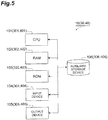
- FIG. 5 is s block diagram showing a hardware configuration of the device shown in Figure 4 .
- the terminal device 10 is configured physically as an ordinary computer system including a CPU (Central Processing Unit) 101, a main memory such as a RAM (Random Access Memory) 102 and a ROM (Read Only Memory) 103, an input device 104 such as a touch panel and a keyboard, an output device 105 such as a display, an auxiliary storage device 106 such as a hard disk, and the like.
- a CPU Central Processing Unit
- main memory such as a RAM (Random Access Memory) 102 and a ROM (Read Only Memory) 103
- an input device 104 such as a touch panel and a keyboard
- an output device 105 such as a display
- an auxiliary storage device 106 such as a hard disk, and the like.
- the terminal device 10 functions of the terminal device 10 are implemented by that the CPU 101 reads predetermined computer software into the hardware such as RAM 102 and ROM 103 to cause the input device 104 and output device 105 to operate under control of the CPU 101, and to read and write data from and into the main memory or the auxiliary storage device 106.
- the terminal device 10 may include hardware other than those described above.
- the terminal device 10 may include a GPU (Graphics Processing Unit), a FPGA (Field-Programmable Gate Array), a DSP (Digital Signal Processor), or the like.
- the hardware of the training device 30 and conversion device 40 can be also configured by the hardware the same as the terminal device 10.
- the training device 30 is configured physically as an ordinary computer system including a CPU 301, a main memory such as a RAM 302 and a ROM 303, an input device 304, an output device 305, an auxiliary storage device 306, and the like.
- the conversion device 40 is configured physically as an ordinary computer system including a CPU 401, a main memory such as a RAM 402 and a ROM 403, an input device 404, an output device 405, an auxiliary storage device 406, and the like.
- Functions of the conversion device 40 are implemented by that the CPU 401 reads predetermined computer software into the hardware such as RAM 402 and ROM 403 to cause the input device 404 and output device 405 to operate under control of the CPU 401, and to read and write data from and into the main memory or the auxiliary storage device 406.
- the training device 30 and the conversion device 40 are not necessarily accommodated as the hardware in one housing, and may be separated into some devices.
- the training device 30 collects and is trained with the image data.
- the training device 30, which is connected with a database 21 storing the image data, a camera 22 generating the image data, a website 23 from which the image data can be downloaded, and the like, can acquire the image data that is the input data for training.
- the training device 30 may be connected to an external storage medium to acquire the image data, or receive the image data via communication, and is not limited to the aspect of image data acquisition.
- the training device 30 includes a platform for establishing a neural network through machine learning.
- the platform is an operating environment for machine learning of a training model base on training data.
- the training model is a network structure, weight data, and the like, for example, and training data is image data, for example.
- the platform includes framework that is a software group performing the machine learning. For the platform and the framework, there are a plurality of formats for a training result depending on a difference in a language used, a difference in a design concept, or the like.
- the training device 30 includes a first platform 31 and a second platform 32.
- the first platform 31 and the second platform 32 are platforms different from each other.
- the training device 30 outputs the trained models different from each other in the format as the training results.
- the training result includes the network structure and the weight data.
- the conversion device 40 converts the training results different in the format acquired from the training device 30 into those having a uniform format, and provides the converted results to the terminal device 10. This allows the terminal device 10 to use the training result trained by any platform.
- the conversion device 40 includes a conversion unit 41.
- the conversion unit 41 acquires the network structure and the weight data from the training device 30 (an example of an external device) and converts the acquired network structure and weight data into a training result M1 having a uniform format (an example of a predetermined format).
- the conversion device 40 not only converts the format of the training result but also performs a predetermined process on the training result M1 such that an operation of the recognition unit 11 in the terminal device 10 is efficient.
- the conversion device 40 is configured to be able to execute acquiring, from the terminal device 10 (an example of the processing device) in which calculation for processing the input data is performed using the network structure and the weight data, a calculation cost in a case of calculating, for each of respective layers of the network structure, in at least one of calculation schemes prepared in advance for the respective layers of the network structure.
- the conversion device 40 includes a data acquisition unit 42.
- the data acquisition unit 42 in the conversion device 40 acquires, for respective layers of the network structure, the calculation cost in the case of calculating in the calculation scheme prepared in advance for each of the respective layers of the network structure, from the terminal device 10.
- Acquiring the calculation cost for each of the respective layers of the network structure means acquiring the calculation cost for each of the respective layers of the neural network described above, and as an example, the data acquisition unit 42 acquires the calculation cost for each intermediate layer 112.
- the data acquisition unit 42 acquires a calculation cost, from a result of actually performing the process in calculation schemes prepared for the respective layers, such as a calculation cost for each of a plurality of algorithms prepared for a first convolutional layer, a calculation cost for each of a plurality of algorithms prepared for a first fully connected layer, and a calculation cost of one algorithm prepared for a second convolutional layer.
- the data acquisition unit 42 acquires a results list TD2 in which a layer, a calculation scheme, and the calculation cost are associated with each other from the terminal device 10.
- the results list TD2 is also referred to as a profile.
- the conversion device 40 includes a link unit 43 which links the results list TD2 acquired by the data acquisition unit 42 with the training result M1.
- the link unit 43 stores information of the selected algorithm in an attribute data area of data of the training result. By doing so, the link unit 43 generates a training result M2 associated with the results list TD2.
- the training result M2 is data output to the terminal device 10.
- the terminal device 10 includes not only the recognition unit 11 but also a candidate decision unit 12, a pre-calculation unit 14, and a cost acquisition unit 15 so that the data acquisition unit 42 described above can acquire the results list TD2.
- the pre-calculation unit 14 acquires the training result M1 from the conversion device 40. Then, the pre-calculation unit 14 outputs information of layer included in the training result M1 to the candidate decision unit 12.
- the candidate decision unit 12 prepares at least one calculation scheme for each of the respective layers of the network structure based on the execution environment.
- the candidate decision unit 12 decides a calculation scheme TD1 executable for each layer based on the information of layer included in the training result M1, referring to a hardware configuration profile, a software library and the like in the execution environment for the terminal device 10. This allows the calculation scheme to be prepared for each layer before the performance of the pre-calculation unit 14.
- the calculation scheme TD1 includes a plurality of algorithms which are executable in the execution environment and exert the same function using arithmetic operations different from each other, for example.
- Examples of the calculation scheme TD1 include an algorithm in which an order of a loop hierarchy is different, an algorithm using a CPU extension function, and an algorithm not using the CPU extension function.
- the calculation scheme TD1 may use the same resource or different resources.
- the calculation scheme TD1 may include a plurality of algorithms which are executable in the execution environment and performs the same arithmetic operation using resources different from each other, for example.
- Examples of the calculation scheme TD1 include the same algorithms different in parameters (such as a thread to be used, a cache size to be used), an algorithm performing an arithmetic operation using a CPU and an algorithm performing an arithmetic operation using a GPU, and an algorithm using a hardware acceleration and an algorithm not using a hardware acceleration.
- the pre-calculation unit 14 performs the calculation for each of the respective layers of the network structure on predetermined data using the calculation scheme TD1 prepared in advance for each of the respective layers of the network structure, in the terminal device 10.
- the predetermined data may be any data so long as it is data which is processable in the neural network and predefined, and may be test data prepared in advance.
- the pre-calculation unit 14 exhaustively performs the calculation scheme TD1. For example, in a case where three calculation schemes are prepared for a convolutional layer, the pre-calculation unit 14 performs the calculation of the convolutional layer in each of the calculation schemes one or more times.
- the cost acquisition unit 15 acquires the calculation cost of at least one calculation scheme for each of the respective layers of the network structure based on a result of the calculation by the pre-calculation unit 14.
- the cost acquisition unit 15 generates the results list TD2 in which a layer, a calculation scheme, a calculation cost are associated with each other.
- the cost acquisition unit 15 generates the results list TD2 in which a layer, a calculation scheme, and an arithmetic operation speed.
- the results list TD2 is output to the conversion device 40 and acquired by the data acquisition unit 42 as described above.
- the terminal device 10 further includes an acquisition unit 16 and a decision unit 17.
- the acquisition unit 16 acquires the training result M2 associated with the results list TD2 from the conversion device 40.
- the decision unit 17 selects one calculation scheme for each of the respective layers of the network structure based on the calculation cost from among the calculation schemes prepared in advance for the respective layers based on the training result M2 to associate the layer of network structure with the selected one calculation scheme.
- the decision unit 17 selects the calculation scheme of which the calculation cost is the lowest, for example.
- the decision unit 17 selects an algorithm of which a calculation cost is the lowest from among a plurality of algorithms prepared for the first convolutional layer. Then, the decision unit 17 associates the first convolutional layer with the selected algorithm.
- the term "associate" means that a specific algorithm is made to be able to be called for calculating a specific layer.
- the recognition unit 11 refers to the training result M2, and performs calculation for each of the respective layers of the network structure on the input data in the execution environment using the calculation scheme associated with each layer of the network structure by the decision unit 17. This improves recognition process efficiency.
- the conversion device 40 may change a data array (data order) of the training result.
- the training result is data in which the weight data is very large volume. For this reason, a data array of the weight data may be changed to be easy to refer to by the terminal device 10.
- the conversion device 40 may include a first adjustment unit 44 for such a process.
- the first adjustment unit 44 may change a data array of the weight data for the training result M1, or may change a data array of the weight data for the training result M2.
- a description is given as an example of a case where the first adjustment unit 44 changes the data array of the weight data for the training result M1.
- the first adjustment unit 44 changes the data array of the weight data for the training result M1 based on the execution environment for the terminal device 10. For example, the first adjustment unit 44 changes the data array of the weight data such that the data becomes a state of being easy to be placed on a cache depending on a cache size of the terminal device 10 or the like. This allows the pre-calculation unit 14 and the recognition unit 11 to perform calculation based on the weight data adjusted by the first adjustment unit.
- the conversion device 40 may perform a preprocess related to the calculation of the recognition unit 11 on the weight data.
- the conversion device 40 may include a second adjustment unit 45 for such a process.
- the second adjustment unit 45 may perform a preprocess of offline compiling.
- the link unit 43 may encrypt the training result M2 for security improvement.
- Figure 6 is a flowchart of a converting process. The flowchart shown in Figure 6 is performed by the conversion unit 41 in the conversion device 40.
- the conversion unit 41 in the conversion device 40 acquires a training model (network structure and weight data) from the training device 30, as a model acquiring process (S10). Subsequently, the conversion unit 41 converts the training model acquired in the model acquiring process (S10) into a uniform format, as a format converting process (S12). Subsequently, the conversion unit 41 outputs the training result M1 in the uniform format, as a model outputting process (S14). When the model outputting process (S14) is completed, the flowchart in Figure 6 ends.
- a training model network structure and weight data
- Figure 7 is a flowchart of a profile acquiring process. The flowchart shown in Figure 7 is performed by the terminal device 10.
- the pre-calculation unit 14 in the terminal device 10 acquires the training result M1, as a training result acquiring process (S20). Subsequently, the pre-calculation unit 14 acquires the calculation scheme TD1 prepared in advance, as a calculation scheme acquiring process (S22). The pre-calculation unit 14 refers to the calculation scheme TD1 stored by the candidate decision unit 12. Subsequently, the pre-calculation unit 14 inputs the test data to the training result M1 and exhaustively performs the prepared calculation schemes, as a pre-calculating process (S24), At this time, a processing speed or usage resource for each calculation scheme is measured as an arithmetic operation cost.
- the cost acquisition unit 15 in the terminal device 10 generates the results list TD2 in which a layer, a calculation scheme, and an arithmetic operation are associated with each other based on a time and the usage resource required for calculation by the pre-calculation unit 14, as a cost acquiring process (S26).
- a cost acquiring process S26
- the flowchart in Figure 7 ends. Note that an execution order of the training result acquiring process (S20) and the calculation scheme acquiring process (S22) may be reversed.
- the pre-calculating process S24 and the cost acquiring process may be alternately performed every layer.
- the flowchart shown in Figure 7 is performed so that an operation result of the operating environment can be acquired.
- Figure 8 is a flowchart of an information giving process. The flowchart shown in Figure 8 is performed by the conversion device 40.
- the data acquisition unit 42 in the conversion device 40 acquires the results list TD2 from the terminal device 10, as a results list acquiring process (S30). Subsequently, the link unit 43 links the training result M1 with the results list TD2 (profile) to generate the training result M2, as a linking process (S34). When the linking process (S34) is completed, the flowchart shown in Figure 8 ends.
- the flowchart shown in Figure 8 is performed so that the training result M2 to which a result of the calculation cost is given is generated.
- Figure 9 is a flowchart of a calculating process. The flowchart shown in Figure 9 is performed by the terminal device 10.
- the terminal device 10 secures a memory required for the process, as a first initializing process (S40). Subsequently, the recognition unit 11 in the terminal device 10 reads the training result M2 acquired from the conversion device 40, as a training result reading process (S42). Similarly, the recognition unit 11 in the terminal device 10 reads the results list TD2 given to the training result M2 acquired from the conversion device 40, as a profile reading process (S44). Subsequently, the terminal device 10 secures a memory required for the process, as a second initializing process (S46). Subsequently, the recognition unit 11 inputs data to be identified, as an input data reading process (S48).
- the recognition unit 11 performs a calculating process for recognition in each layer, as a calculating process (S50).
- the results list TD2 read in the profile reading process (S44) is used.
- the calculating process (S50) is described later in detail ( Figure 10 ).
- the recognition unit 11 outputs a result of recognition, as a result outputting process (S52), When the result outputting process (S52) is completed, the flowchart shown in Figure 9 ends.
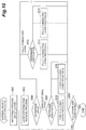
- FIG 10 is a flowchart of a calculating process and illustrates the calculating process (S50) in Figure 9 in detail.
- the recognition unit 11 inputs all pixel values corresponding to one image to the input layer, as an inputting process (S60). Subsequently, the recognition unit 11 inputs information of a layer to be processed, as a layer information reading process (S62). In the information of layer, included is information identifying which layer of the neural network is the layer to be processed. Subsequently, the recognition unit 11 branches the process based on the identification information acquired in the layer information reading process (S62), as a layer determining process (S64).
- the decision unit 17 refers to the results list TD2 and specifies a calculation scheme of which a calculation cost is the smallest in a convolutional layer process, as an association determining process (S66). In a case where the calculation cost is the smallest in a convolutional layer process A, the decision unit 17 associates the convolutional layer process A with the layer to be processed. Then, the recognition unit 11 performs the convolutional layer process A, as a performing process (S68). On the other hand, in a case where the calculation cost is the smallest in a convolutional layer process B, the decision unit 17 associates the convolutional layer process B with the layer to be processed.
- the convolutional layer process B is a process in which the function is the same as the above but implementation is different. Then, the recognition unit 11 performs the convolutional layer process B, as a performing process (S70). In the above example, two cases that the calculation scheme is the convolutional layer process A and that the calculation scheme is the convolutional layer process B are described, but the number of the processes may be three or more. In this way, the decision unit 17 branches the process depending on the results list TD2.
- the decision unit 17 refers to the results list TD2 and specifies a calculation scheme of which a calculation cost is the smallest in a fully connected layer process, as an association determining process (S72). In a case where the calculation cost is the smallest in a fully connected layer process A, the decision unit 17 associates the fully connected layer process A with the layer to be processed. Then, the recognition unit 11 performs the fully connected layer process A, as a performing process (S74). On the other hand, in a case where the calculation cost is the smallest in a fully connected layer process B, the decision unit 17 associates the fully connected layer process B with the layer to be processed.
- the fully connected layer process B is a process in which the function is the same as the above but implementation is different. Then, the recognition unit 11 performs the fully connected layer process B, as a performing process (S76). In the above example, two cases that the calculation scheme is the fully connected layer process A and that the calculation scheme is the fully connected layer process B are described, but the number of the processes may be three or more. In this way, the decision unit 17 branches the process depending on the results list TD2.
- the layer to be processed is a further another layer, for example, a pooling layer, an activation function layer, or the like, the same processes as for the convolutional layer and the fully connected layer are performed.
- the recognition unit 11 determines whether or not the process is completed for all layers of the neural network, as a determining process (S80). In a case where the process is determined to be not completed for all layers, the process goes to the layer information reading process (S62) to continue the process on the next layer. In a case that the process is determined to be completed for all layers, the flowchart shown in Figure 10 ends.
- the calculation scheme decision program includes a main module, a pre-calculation module, a cost acquisition module, a decision module, and a calculation module.
- the main module is a part for collectively controlling the device.
- the functions realized by performing the pre-calculation module, the cost acquisition module, the decision module, and the calculation module are respectively similar to the functions of the above described pre-calculation unit 14, cost acquisition unit 15, decision unit 17, and recognition unit 11.
- the program is provided by way of a non-transitory record such as the ROM or a semiconductor memory medium, for example.
- the program may be provided through a communication of a network or the like.
- calculation scheme decision system 100 one calculation scheme is selected for each layer, from among the calculation schemes prepared in advance, based on the calculation cost obtained by actually operating those calculation schemes in the execution environment. In this way, the calculation scheme decision system 100 can take into account the calculation cost to decide an optimal calculation scheme for each layer. Therefore, the calculation scheme decision system 100 can take into account the calculation cost to decide the calculation scheme.
- the calculation scheme decision system 100 can actually operate, in the execution environment, a plurality of algorithms which output the same results but are different from each other in the arithmetic operation method, and decide an optimal algorithm based on the obtained calculation costs.
- the calculation scheme decision system 100 because of including the candidate decision unit 12, can prepare the calculation scheme taking into account the resources in the execution environment.
- the calculation scheme decision system 100 because of including the conversion unit 41, can deal with the training result of the training device 30 in a predetermined format.
- the calculation scheme decision system 100 because of including the first adjustment unit 44, can change the data array of the weight data such that the data becomes a state of being easy to be placed on a cache.
- the calculation scheme decision system 100 because of including the second adjustment unit 45, can reduce a calculation load on the recognition unit 11.
- a calculation scheme decision system 100A according to a second embodiment is different in that the function of the decision unit 17 is on the conversion device 40 side, and the same in other aspects, as compared with the calculation scheme decision system 100 according to the first embodiment.
- the description the same as in the first embodiment is not repeated.
- Figure 11 is a functional block diagram of a calculation scheme decision system 100A according to the second embodiment.
- the calculation scheme decision system 100A includes a conversion device 40A (an example of the calculation scheme decision device) and a terminal device 10A.
- the conversion device 40A is different in including a decision unit 17A as compared with the conversion device 40.
- the decision unit 17A is different in an input source and an output destination and the same as in other configurations as compared with the decision unit 17.
- the decision unit 17A selects one calculation scheme for each of the respective layers of the network structure based on the calculation cost from among the calculation schemes prepared in advance for the respective layers based on the results list TD2 to associate the layer of network structure with the selected one calculation scheme.
- a link unit 43A gives the correspondence relation associated by the decision unit 17A to the training result M1.
- the link unit 43A does not give the results list TD2 as it is to training result M1, but gives the result derived from the results list TD2 to the training result M1. By doing so, a training result M3 is generated.
- An acquisition unit 16A is different in acquiring the training result M3 and the same as in other configurations as compared with the acquisition unit 16.
- the acquisition unit 16A acquires the network structure, the weight data, and a correspondence relation between the layer of the network structure and the calculation scheme. This allows the recognition unit 11 to use the correspondence relation associated by the decision unit 17A to perform the calculation for each of the respective layers of the network structure on the input data.
- calculation scheme decision system 100A Other configurations of the calculation scheme decision system 100A are the same as those of the calculation scheme decision system 100.
- An operation of the calculation scheme decision system 100A is different in the information giving process ( Figure 8 ) and the calculating process ( Figure 9 and Figure 10 ), and the same as in other operations as compared with the operation of the calculation scheme decision system 100.
- Figure 12 is a flowchart of an information giving process. The flowchart shown in Figure 12 is performed by the conversion device 40A.
- the data acquisition unit 42 in the conversion device 40A acquires the results list TD2 from the terminal device 10, as a results list acquiring process (S300).
- the decision unit 17A in the conversion device 40 selects one calculation scheme for each of the respective layers of the network structure based on the calculation cost acquired by the data acquisition unit 42, from among the calculation schemes prepared in advance for the respective layers, as a deciding process (S320).
- the link unit 43 links the training result M1 with one calculation scheme selected for each layer to generate the training result M3, as a linking process (S340).
- the linking process (S340) is completed, the flowchart shown in Figure 12 ends.
- the flowchart shown in Figure 12 is performed so that the training result M3 to which a result of the calculation cost is given is generate.
- Figure 13 is a flowchart of a calculating process. The flowchart shown in Figure 13 is performed by the terminal device 10A.
- the terminal device 10A secures a memory required for the process, as a first initializing process (S400). Subsequently, the recognition unit 11 in the terminal device 10A reads the training result M3 acquired from the conversion device 40A, as a training result reading process (S420). Subsequently, the terminal device 10A secures a memory required for the process, as a second initializing process (S460). Subsequently, the recognition unit 11 inputs data to be identified, as an input data reading process (S480). Subsequently, the recognition unit 11 performs a calculating process for recognition in each layer, as a calculating process (S500). The calculating process (S500) is described later in detail ( Figure 14 ). Finally, the recognition unit 11 outputs a result of recognition, as a result outputting process (S520), When the result outputting process (S520) is completed, the flowchart shown in Figure 13 ends.
- Figure 14 is a flowchart of a calculating process. The flowchart shown in Figure 14 is performed by the terminal device 10A.
- the recognition unit 11 inputs all pixel values corresponding to one image to the input layer, as an inputting process (S600). Subsequently, the recognition unit 11 inputs information of a layer to be processed, as a layer information reading process (S620). In the information of layer, included is information identifying which layer of the neural network is the layer to be processed. Subsequently, the recognition unit 11 reads the correspondence relation given to the training result M3 to specify the calculation scheme associated with the layer, as a calculation scheme specifying process (S622). Subsequently, the recognition unit 11 performs the calculating process for recognition in the calculation scheme specified in the correspondence relation, as a calculating process (S624).
- the recognition unit 11 determines whether or not the process is completed for all layers of the neural network, as a determining process (S800). In a case where the process is determined to be not completed for all layers, the process goes to the layer information reading process (S620) to continue the process on the next layer. In a case that the process is determined to be completed for all layers, the flowchart shown in Figure 14 ends.
- a processing program and a calculation scheme decision program causing to function as the terminal device 10A and the conversion device 40A include modules corresponding to function units of the devices similar to the program described in the first embodiment.
- calculation scheme decision system 100A one calculation scheme is selected for each layer, from among the calculation schemes prepared in advance, based on the calculation cost obtained by actually operating those calculation schemes in the execution environment. In this way, the calculation scheme decision system 100A can take into account the calculation cost to decide an optimal calculation scheme for each layer. Therefore, the calculation scheme decision system 100A can take into account the calculation cost to decide the calculation scheme.
- the calculation scheme decision system 100 is illustrated to include the terminal device 10 and the conversion device 40 as the hardware, but is not limited thereto.
- the calculation scheme decision system 100 may be configured as a collection of devices prepared for respective functions connected to each other through a communication network, such as a device for the pre-calculation unit 14, a device for the cost acquisition unit 15, a device for the decision unit 17, and a device for the recognition unit 11.
- the calculation scheme decision system 100 may be constituted by single hardware capable of exerting the all functions.
- the calculation scheme decision system 100A may similarly be constituted by various hardware or single hardware.
- the calculation scheme decision system 100 decides an optimal calculation scheme for each layer for the recognition unit 11, one set of optimal calculation schemes is provided to one recognition unit 11.
- the number of sets of optimal calculation schemes provided is not limited to one, and two or more sets may be provided.
- the recognition unit 11 may perform each of a plurality of sets provided to select a set in which the process can be performed the fastest, for example.
- the calculation scheme decision system 100 may develop an optimal calculation scheme for another terminal having the same environment. For example, assume that there is a terminal device 10X (an example of a second terminal) having an environment the same as the terminal device 10 (an example of a first terminal). The terminal device 10X is a model the same as the terminal device 10, for example.
- the calculation scheme decision system 100 may further include a provision unit providing the calculation scheme decided by the decision unit 17 to the terminal device 10X. In this case, the calculation scheme decision system 100 can, without calculating in a terminal in the same environment, apply the calculation scheme decided in another terminal having the same environment.
Landscapes
- Engineering & Computer Science (AREA)
- Theoretical Computer Science (AREA)
- Physics & Mathematics (AREA)
- Computing Systems (AREA)
- Software Systems (AREA)
- Artificial Intelligence (AREA)
- Mathematical Physics (AREA)
- Computational Linguistics (AREA)
- Data Mining & Analysis (AREA)
- Evolutionary Computation (AREA)
- General Physics & Mathematics (AREA)
- General Engineering & Computer Science (AREA)
- Biomedical Technology (AREA)
- Molecular Biology (AREA)
- General Health & Medical Sciences (AREA)
- Biophysics (AREA)
- Life Sciences & Earth Sciences (AREA)
- Health & Medical Sciences (AREA)
- Image Analysis (AREA)
Abstract
Description
- The present disclosure relates to a calculation scheme decision system, a calculation scheme decision device, a processing device, a calculation scheme decision method, a processing method, a calculation scheme decision program, and a processing program.
-
Patent Document 1 discloses a recognition device having a hierarchical network including a plurality of layers of an input layer, a middle layer, and an output layer. The recognition device performs recognition using a network structure and weight data trained by a training device. - Patent Document 1: Japanese Laid-open Patent Publication No.
2016-157426 - In general, a recognition device may be equipment such as a mobile terminal or a camera which is reduced in size but lower in a processing capability as compared with a training device. As an image sensor is enhanced in performance and a capacity for communication data is increased, a processing time for input data and a resource required for processing tend to increase in the recognition device.
- In this technical field, as for a device performing calculation for processing input data using a network structure and weight data, there is a demand for a calculation scheme decision system, a calculation scheme decision device, a processing device, a calculation scheme decision method, a processing method, a calculation scheme decision program, and a processing program which are capable of deciding a calculation scheme taking into account a calculation cost.
- An aspect of the present disclosure is a calculation scheme decision system including a pre-calculation unit configured to perform, in an execution environment in which calculation for processing input data is performed using a network structure and weight data, calculation for each of respective layers of the network structure on predetermined data using at least one of calculation schemes prepared in advance for the respective layers of the network structure, a cost acquisition unit configured to acquire a calculation cost of the at least one calculation scheme for each of the respective layers of the network structure based on a result of the calculation by the pre-calculation unit, a decision unit configured to select one calculation scheme for each of the respective layers of the network structure based on the calculation cost from among the at least one of the calculation schemes prepared in advance for the respective layers to associate the layer of the network structure with the selected one calculation scheme, and a calculation unit configured to perform the calculation for each of the respective layers of the network structure on the input data in the execution environment using the calculation scheme associated with each layer of the network structure by the decision unit.
- In the calculation scheme decision system, one calculation scheme is selected for each layer, from among the calculation schemes prepared in advance, based on the calculation cost obtained by actually operating those calculation schemes in the execution environment. In this way, the calculation scheme decision system can take into account the calculation cost to decide an optimal calculation scheme for each layer. Therefore, the calculation scheme decision system can take into account the calculation cost to decide the calculation scheme.
- In an embodiment, the at least one calculation scheme may include a plurality of algorithms executable in the execution environment and exerting the same function using arithmetic operations different from each other. In this case, the calculation scheme decision system can actually operate, in the execution environment, a plurality of algorithms which output the same results but are different from each other in the arithmetic operation method, and decide an optimal algorithm based on the obtained calculation costs.
- In an embodiment, at least one calculation scheme may include a plurality of algorithms executable in the execution environment and performing the same arithmetic operation using resources different from each other. In this case, the calculation scheme decision system can actually operate, in the execution environment, a plurality of algorithms which use the same arithmetic operation and output the same results but are different from each other in the usage resource, and decide an optimal algorithm based on the obtained calculation costs.
- In an embodiment, the calculation scheme decision system may further include a candidate decision unit configured to prepare the at least one calculation scheme for each of the respective layers of the network structure based on the execution environment. In this case, the calculation scheme decision system can prepare the calculation scheme taking into account the resources in the execution environment.
- In an embodiment, the calculation scheme decision system may include a conversion unit configured to acquire the network structure and the weight data from an external device and convert the acquired network structure and weight data into a predetermined format. In this case, the calculation scheme decision system can deal with the training result of the external device in the predetermined format.
- In an embodiment, the calculation scheme decision system may further include a first adjustment unit configured to change a data order of the weight data based on the execution environment, wherein the pre-calculation unit and the calculation unit perform calculation based on the weight data adjusted by the first adjustment unit. In this case, the calculation scheme decision system can change the data array of the weight data such that the data becomes a state of being easy to be placed on a cache.
- In an embodiment, the calculation scheme decision system may further include a second adjustment unit configured to perform a preprocess related to the calculation of the calculation unit on the weight data, wherein the pre-calculation unit and the calculation unit perform calculation based on the weight data adjusted by the second adjustment unit. In this case, the calculation scheme decision system can reduce a calculation load on the calculation unit.
- In an embodiment, the pre-calculation unit and the calculation unit are included in a first terminal, and the calculation scheme decision system may further include a provision unit configured to provide the calculation scheme decided by the decision unit to a second terminal having an execution environment the same as an execution environment of the first terminal. In this case, the calculation scheme decision system can, without calculating in a terminal in the same environment, apply the calculation scheme decided in another terminal having the same environment.
- Another aspect of the present disclosure is a calculation scheme decision device including a data acquisition unit configured to acquire, from a processing device in which calculation for processing input data is performed using a network structure and weight data, a calculation cost in a case of calculating, for each of respective layers of the network structure, in at least one of calculation schemes prepared in advance for the respective layers of the network structure, and a decision unit configured to select one calculation scheme for each of the respective layers of the network structure based on the calculation cost from among the at least one of the calculation schemes prepared in advance for the respective layers to associate the layer of the network structure with the selected one calculation scheme.
- The calculation scheme decision device can take into account the calculation cost to decide an optimal calculation scheme for each layer. Therefore, the calculation scheme decision device can take into account the calculation cost to change the calculation scheme.
- Another aspect of the present disclosure is a processing device including an acquisition unit configured to acquire a network structure, weight data, and a correspondence relation between the layer of the network structure and a calculation scheme, and a calculation unit configured to perform calculation for each of respective layers of the network structure on input data based on the network structure, the weight data, and the correspondence relation acquired by the acquisition unit.
- The processing device, in performing the calculation for each of the respective layers of the network structure on the input data, can change the calculation scheme for each layer.
- Another aspect of the present disclosure is a calculation scheme decision method including performing, in an execution environment in which calculation for processing input data is performed using a network structure and weight data, calculation for each of respective layers of the network structure on predetermined data using at least one of calculation schemes prepared in advance for the respective layers of the network structure, acquiring a calculation cost of the at least one calculation scheme for each of the respective layers of the network structure based on a result of the calculation for each of the respective layers of the network structure, selecting one calculation scheme for each of the respective layers of the network structure based on the calculation cost from among the at least one of the calculation schemes prepared in advance for the respective layers to associate the layer of the network structure with the selected one calculation scheme, and performing the calculation for each of the respective layers of the network structure on the input data in the execution environment using the calculation scheme associated with each layer of the network structure.
- The calculation scheme decision method exerts the same effect as the calculation scheme decision system described above.
- Another aspect of the present disclosure is a calculation scheme decision method inluding acquiring, from a processing device in which calculation for processing input data is performed using a network structure and weight data, a calculation cost in a case of calculating, for each of respective layers of the network structure, in at least one of calculation schemes prepared in advance for the respective layers of the network structure, and selecting one calculation scheme for each of the respective layers of the network structure based on the calculation cost from among the at least one of the calculation schemes prepared in advance for the respective layers to associate the layer of the network structure with the selected one calculation scheme.
- The calculation scheme decision method exerts the same effect as the calculation scheme decision device described above.
- Another aspect of the present disclosure is a processing method including acquiring a network structure, weight data, and a correspondence relation between a layer of a network structure and a calculation scheme, and performing calculation for each of respective layers of the network structure on input data based on the network structure, the weight data, and the correspondence relation.
- The processing method exerts the same effect as the processing device described above.
- Another aspect of the present disclosure is a calculation scheme decision program causing a computer to operate. The calculation scheme decision program causes the computer to function as a pre-calculation unit configured to perform, in an execution environment in which calculation for processing input data is performed using a network structure and weight data, calculation for each of respective layers of the network structure on predetermined data using at least one of calculation schemes prepared in advance for the respective layers of the network structure, a cost acquisition unit configured to acquire a calculation cost of the at least one calculation scheme for each of the respective layers of the network structure based on a result of the calculation by the pre-calculation unit, a decision unit configured to select one calculation scheme for each of the respective layers of the network structure based on the calculation cost from among the at least one of the calculation schemes prepared in advance for the respective layers to associate the layer of the network structure with the selected one calculation scheme, and a calculation unit configured to perform the calculation for each of the respective layers of the network structure on the input data in the execution environment using the calculation scheme associated with each layer of the network structure by the decision unit.
- The calculation scheme decision program exerts the same effect as the calculation scheme decision system described above.
- Another aspect of the present disclosure is a calculation scheme decision program causing a computer to operate. The calculation scheme decision program causes the computer to function as a data acquisition unit configured to acquire, from a processing device in which calculation for processing input data is performed using a network structure and weight data, a calculation cost in a case of calculating, for each of respective layers of the network structure, in at least one of calculation schemes prepared in advance for the respective layers of the network structure, and a decision unit configured to select one calculation scheme for each of the respective layers of the network structure based on the calculation cost from among the at least one of the calculation schemes prepared in advance for the respective layers to associate the layer of the network structure with the selected one calculation scheme.
- The calculation scheme decision program exerts the same effect as the calculation scheme decision device described above.
- Another aspect of the present disclosure is a processing program causing a computer to operate. The processing program causes the computer to function as an acquisition unit configured to acquire a network structure, weight data, and a correspondence relation between a layer of a network structure and a calculation scheme, and a calculation unit configured to perform calculation for each of respective layers of the network structure on input data based on the network structure, the weight data, and the correspondence relation acquired by the acquisition unit.
- The processing program exerts the same effect as the processing device described above.
- According to various aspects of the present disclosure, it is possible to change a calculation scheme taking into account a calculation cost in a device performing calculation for processing input data using a network structure and weight data.
-
- [
Figure 1] Figure 1 is a diagram illustrating a recognition unit. - [
Figure 2] Figure 2 is a diagram illustrating a neural network in the recognition unit. - [
Figure 3] Figure 3 is a diagram illustrating artificial neurons shown inFigure 2 . - [
Figure 4] Figure 4 is a functional block diagram of a calculation scheme decision system according to a first embodiment. - [
Figure 5] Figure 5 is s block diagram showing a hardware configuration of a device shown inFigure 4 . - [
Figure 6] Figure 6 is a flowchart of a converting process. - [
Figure 7] Figure 7 is a flowchart of a profile acquiring process. - [
Figure 8] Figure 8 is a flowchart of an information giving process. - [
Figure 9] Figure 9 is a flowchart of a calculating process. - [
Figure 10] Figure 10 is a flowchart of a calculating process. - [
Figure 11] Figure 11 is a functional block diagram of a calculation scheme decision system according to a second embodiment. - [
Figure 12] Figure 12 is a flowchart of an information giving process. - [
Figure 13] Figure 13 is a flowchart of a calculating process. - [
Figure 14] Figure 14 is a flowchart of a calculating process. - Hereinafter, a description is given of embodiments with reference to the drawings. Note that in description of the drawings the same components are designated by the same reference signs, and the duplicated description is not repeated.
- A calculation scheme decision system 100 (see
Figure 4 ) according to an embodiment is a system which decides an optimal calculation scheme for a processing device having a hierarchical network. The hierarchical network is a network having a hierarchical structure, and examples of the hierarchical network include a neural network. The neural network is defined using a network structure, weight data, and the like. The neural network is described later in detail. - The processing device has an execution environment capable of executing various programs. In the execution environment, calculation for processing input data is performed using the network structure and weight data. The input data is data processed to achieve an aim of the hierarchical network. For example, the input data is recognition target data when the aim of the hierarchical network is recognition. The processing device is not specifically limited so long as it is a device having a hierarchical network. The processing device may be a terminal device labeling content of an image, a monitoring camera identifying an object position within an image (for example, a position of a person, or the like), or a general-purpose personal computer, as an example. In the following description, as an example of the processing device, a terminal device including a
recognition unit 11 which recognizes content of recognition target data using a neural network is described (seeFigure 1 andFigure 4 , an example of a calculation unit). The recognition target data is data to be recognized by a computer, and examples of the recognition target data include image data, voice data, and text data. - A calculation scheme for the
recognition unit 11 decided by the calculationscheme decision system 100 is a scheme for performing an arithmetic operation on an input and outputting a result. The calculationscheme decision system 100, on an assumption that the same result is output for an input with a predetermined accuracy performance, decides an optimal algorithm from among a plurality of kinds of executable algorithms, or an optimal algorithm from among a plurality of identical algorithms different in a usage amount or usage aspect of resources. Examples of the resource include a hardware resource and a software resource. Examples of the hardware resource include a CPU or a cache for performing the arithmetic operation. Examples of the software resource include a library. A resource used by an algorithm may be defined by parameters of the algorithm, for example. - The calculation
scheme decision system 100 takes into account a calculation cost to decide the calculation scheme for therecognition unit 11. The calculation cost is evaluated by a time required for calculation as an example. In this case, the longer the time required for calculation, the more the calculation cost. The calculation cost may be evaluated by the usage amount of resources. In this case, the more the usage amount of resources, the more the calculation cost. The calculation cost may be evaluated by two of the time required for calculation and the usage amount of resources. - The calculation
scheme decision system 100 decides a calculation scheme having the lowest calculation cost from among the calculation schemes executable in the execution environment for therecognition unit 11. The calculationscheme decision system 100 may select the calculation scheme having the calculation cost lower than an average of the calculation costs of the calculation schemes executable. In this way, the calculationscheme decision system 100 optimizes a calculation speed of therecognition unit 11, or optimizes the resource usage amount used by therecognition unit 11. - The calculation
scheme decision system 100 exhaustively performs the calculation schemes executable in the execution environment for therecognition unit 11 in deciding the calculation scheme, and evaluates the calculation schemes based on results of the performing to decide an optimal calculation scheme. - As a specific example, the calculation
scheme decision system 100 is configured to be able to execute performing calculation for each of respective layers of the network structure on predetermined data using at least one of calculation schemes prepared in advance for the respective layers of the network structure in the execution environment for therecognition unit 11, acquiring the calculation cost of at least one calculation schemes for the respective layers of the network structure based on a result of the calculation for each of the respective layers of the network structure, selecting one calculation scheme for each of the respective layers of the network structure, based on the calculation cost, from among at least one of the calculation schemes prepared in advance for the respective layers to associate the layer of the network structure with the selected one calculation scheme, and performing calculation for each of the respective layers of the network structure on the input data in the execution environment using the calculation scheme associated with each layer of the network structure. - First, a description is given of the
recognition unit 11 for which the calculation scheme decision system decides the calculation scheme. Hereinafter, a description is given, as an example, of a case that the recognition target data is the image data, and a target to be recognized is content of an image (person, animal, object, scenery, room, etc.). -
Figure 1 is a diagram illustrating therecognition unit 11. As shown inFigure 1 , therecognition unit 11 is included in aterminal device 10. Therecognition unit 11 inputs recognition target data G1 that is image data, and outputs a recognition result. As shown in (A) ofFigure 1 , the recognition target data G1 is the image data in which a dog is drawn. Therecognition unit 11 inputs the image data (to be more specific, pixel value), and outputs a label representing content of the image by use of a training result (for example, network structure and weight data). The label, which is used to classify the content of the recognition target data, is information for identifying a category set in advance by a system user. In the example in (A) ofFigure 1 , therecognition unit 11 outputs a label of "dog". The label is given to the recognition target data G1 by therecognition unit 11. The term giving means making an association, and, for example, only a relationship between the recognition target data G1 and the label may be recorded by means of an association table or the like, or the label may be incorporated into the recognition target data G1 itself. In general, the label being given to the recognition target data is referred to as annotation. Therecognition unit 11, because of being capable of inputting the image data to give the label, can automatically classify the image data, or search a web for a desired image. - When there is a plurality of labels set in advance by the system user, there are a single-labeling process of giving the most possible label among the labels to the recognition target data, and a multi-labeling process of giving all labels having a certain possibility to the recognition target data. As shown in (B) of
Figure 1 , recognition target data G2 is image data in which a person and flowers are drawn. In a case that therecognition unit 11 performs the single-labeling process, a label of "person" is given to the recognition target data G2 by therecognition unit 11. In a case that therecognition unit 11 performs the multi-labeling process, two labels, the label of "person" and a label of "flower" are given to the recognition target data G2 by therecognition unit 11. -
Figure 2 is a diagram illustrating a neural network in therecognition unit 11. Therecognition unit 11 recognizes a label corresponding to the image data by use of the neural network. The neural network is an information processing system which models a cerebral nervous system. As shown inFigure 2 , the neural network in therecognition unit 11 is a so-called hierarchical neural network, in which many artificial neurons illustrated by circles form a hierarchy and are coupled to each other. The hierarchical neural network includes artificial neurons for input, artificial neurons for processing, and artificial neurons for output. - The artificial neurons for input acquire the recognition target data to distribute to the artificial neurons for processing. Hereinafter, a signal itself communicated in the neural network is referred to as a score. The score is a numerical value. The artificial neurons for input are arranged in parallel to form an
input layer 111. - The artificial neurons for processing which are connected with the artificial neurons for input process inputs in accordance with functions of the artificial neurons to deliver outputs to other neurons. The artificial neurons for processing are arranged in parallel to form an intermediate layer 112. The intermediate layer 112 may be a plurality of layers. Note that three or more hierarchies of neural networks including the intermediate layer 112 are called a deep neural network.
- The artificial neurons for output externally output the recognition score. The number of artificial neurons for output to be prepared is the same as the number of labels. In other words, the recognition score is output for each label in the neural network. In the example in
Figure 2 , three artificial neurons are prepared correspondingly to three labels "dog", "person", and "flower". The artificial neurons for output outputs a recognition score B1 corresponding to the label of "dog", a recognition score B2 corresponding to the label of "person", and a recognition score B3 corresponding to the label of "flower". The recognition score is a score representing a recognition result, and in a case of training assuming that the positive evaluation is "1" and the negative evaluation "0", the higher the recognition score of the label, the higher a possibility that the label represents the content of the image. The artificial neurons for output are arranged in parallel to form anoutput layer 113. - The
recognition unit 11 uses the recognition score output by theoutput layer 113 to decide a label to be given. For example, therecognition unit 11 gives the label corresponding to the recognition score equal to or more than a predetermined value to the recognition target data. This allows the recognition target data to be automatically given the label representing the recognition target data. Note that in the case of the single-labeling process, therecognition unit 11 gives the label corresponding to the highest recognition score to the recognition target data. -
Figure 3 is a diagram illustrating the artificial neurons shown inFigure 2 . The artificial neurons shown in (A) ofFigure 3 input, x1, x2, and x3, and multiply these by corresponding weight coefficients w1, w2, and w3, respectively. The artificial neurons compute a sum of an integrated value (x1·w1·x2·w2·x3·w3) and a bias value b. The sum is substituted into an activating function to obtain an output of the artificial neurons. - To be more specific, the output of the targeted artificial neurons is as the following mathematical expression.

- (B) of
Figure 3 is a diagram illustrating the artificial neurons of N hierarchies (N = 3). As shown in (B) ofFigure 3 , in a case of three hierarchies, outputs h1 (2), h2 (2), and h3 (2) of the artificial neurons in the second hierarchy are as the following mathematical expressions 3 to 5, respectively. Here, n represents the number of artificial neurons in the targeted hierarchy, w1j (1) represents a weight coefficient for the first artificial neuron in the second hierarchy corresponding to an output of the j-th output in the first hierarchy, and b1 (1) represents a bias value for the first hierarchy.


- The artificial neurons are not limited to the above, and may be those generalized. A general expression for a function of the i-th intermediate layer 112 is as the following mathematical expression 7.

Figure 3 is generally as the following mathematical expression 8.

output layer 113 is as the followingmathematical expression 10.
- The network structure, weight coefficient (weight data), and bias value described above are those trained by a
training device 30 described later, and delivered as the training results to therecognition unit 11. In other words, thetraining device 30 is a device training the network structure, weight coefficient, and bias value which make a feature amount of the recognition target data correspond to the label indicating the content thereof. Note that when therecognition unit 11 does not use the bias value b, thetraining device 30 trains only the network structure and weight coefficient. -
Figure 4 is a functional block diagram of the calculationscheme decision system 100 according to the embodiment. As shown inFigure 4 , the calculationscheme decision system 100 includes theterminal device 10 and aconversion device 40, and is connected to thetraining device 30. Thetraining device 30 collects and is trained with the image data. The training result of thetraining device 30 is provided via theconversion device 40 to theterminal device 10. - First, a description is given of hardware of the
terminal device 10, thetraining device 30, andth conversion device 40.Figure 5 is s block diagram showing a hardware configuration of the device shown inFigure 4 . As shown inFigure 5 , theterminal device 10 is configured physically as an ordinary computer system including a CPU (Central Processing Unit) 101, a main memory such as a RAM (Random Access Memory) 102 and a ROM (Read Only Memory) 103, an input device 104 such as a touch panel and a keyboard, an output device 105 such as a display, an auxiliary storage device 106 such as a hard disk, and the like. Functions of theterminal device 10 are implemented by that the CPU 101 reads predetermined computer software into the hardware such as RAM 102 and ROM 103 to cause the input device 104 and output device 105 to operate under control of the CPU 101, and to read and write data from and into the main memory or the auxiliary storage device 106. Note that theterminal device 10 may include hardware other than those described above. For example, theterminal device 10 may include a GPU (Graphics Processing Unit), a FPGA (Field-Programmable Gate Array), a DSP (Digital Signal Processor), or the like. - The hardware of the
training device 30 andconversion device 40 can be also configured by the hardware the same as theterminal device 10. Specifically, thetraining device 30 is configured physically as an ordinary computer system including a CPU 301, a main memory such as a RAM 302 and a ROM 303, an input device 304, an output device 305, an auxiliary storage device 306, and the like. Theconversion device 40 is configured physically as an ordinary computer system including a CPU 401, a main memory such as a RAM 402 and a ROM 403, an input device 404, an output device 405, an auxiliary storage device 406, and the like. Functions of theconversion device 40 are implemented by that the CPU 401 reads predetermined computer software into the hardware such as RAM 402 and ROM 403 to cause the input device 404 and output device 405 to operate under control of the CPU 401, and to read and write data from and into the main memory or the auxiliary storage device 406. Note that thetraining device 30 and theconversion device 40 are not necessarily accommodated as the hardware in one housing, and may be separated into some devices. - First, a description is given of a functional configuration of the
training device 30. Thetraining device 30 collects and is trained with the image data. Thetraining device 30, which is connected with adatabase 21 storing the image data, acamera 22 generating the image data, awebsite 23 from which the image data can be downloaded, and the like, can acquire the image data that is the input data for training. Of course, thetraining device 30 may be connected to an external storage medium to acquire the image data, or receive the image data via communication, and is not limited to the aspect of image data acquisition. - The
training device 30 includes a platform for establishing a neural network through machine learning. The platform is an operating environment for machine learning of a training model base on training data. The training model is a network structure, weight data, and the like, for example, and training data is image data, for example. The platform includes framework that is a software group performing the machine learning. For the platform and the framework, there are a plurality of formats for a training result depending on a difference in a language used, a difference in a design concept, or the like. - As an example, the
training device 30 includes afirst platform 31 and asecond platform 32. Thefirst platform 31 and thesecond platform 32 are platforms different from each other. Specifically, thetraining device 30 outputs the trained models different from each other in the format as the training results. The training result includes the network structure and the weight data. - The
conversion device 40 converts the training results different in the format acquired from thetraining device 30 into those having a uniform format, and provides the converted results to theterminal device 10. This allows theterminal device 10 to use the training result trained by any platform. - The
conversion device 40 includes aconversion unit 41. Theconversion unit 41 acquires the network structure and the weight data from the training device 30 (an example of an external device) and converts the acquired network structure and weight data into a training result M1 having a uniform format (an example of a predetermined format). - The
conversion device 40 not only converts the format of the training result but also performs a predetermined process on the training result M1 such that an operation of therecognition unit 11 in theterminal device 10 is efficient. Specifically, theconversion device 40 is configured to be able to execute acquiring, from the terminal device 10 (an example of the processing device) in which calculation for processing the input data is performed using the network structure and the weight data, a calculation cost in a case of calculating, for each of respective layers of the network structure, in at least one of calculation schemes prepared in advance for the respective layers of the network structure. - For such a process, the
conversion device 40 includes adata acquisition unit 42. Thedata acquisition unit 42 in theconversion device 40 acquires, for respective layers of the network structure, the calculation cost in the case of calculating in the calculation scheme prepared in advance for each of the respective layers of the network structure, from theterminal device 10. Acquiring the calculation cost for each of the respective layers of the network structure means acquiring the calculation cost for each of the respective layers of the neural network described above, and as an example, thedata acquisition unit 42 acquires the calculation cost for each intermediate layer 112. As a specific example, thedata acquisition unit 42 acquires a calculation cost, from a result of actually performing the process in calculation schemes prepared for the respective layers, such as a calculation cost for each of a plurality of algorithms prepared for a first convolutional layer, a calculation cost for each of a plurality of algorithms prepared for a first fully connected layer, and a calculation cost of one algorithm prepared for a second convolutional layer. As a more specific example, thedata acquisition unit 42 acquires a results list TD2 in which a layer, a calculation scheme, and the calculation cost are associated with each other from theterminal device 10. Hereinafter, the results list TD2 is also referred to as a profile. - The
conversion device 40 includes alink unit 43 which links the results list TD2 acquired by thedata acquisition unit 42 with the training result M1. As an example, thelink unit 43 stores information of the selected algorithm in an attribute data area of data of the training result. By doing so, thelink unit 43 generates a training result M2 associated with the results list TD2. The training result M2 is data output to theterminal device 10. - The
terminal device 10 includes not only therecognition unit 11 but also acandidate decision unit 12, apre-calculation unit 14, and acost acquisition unit 15 so that thedata acquisition unit 42 described above can acquire the results list TD2. - The
pre-calculation unit 14 acquires the training result M1 from theconversion device 40. Then, thepre-calculation unit 14 outputs information of layer included in the training result M1 to thecandidate decision unit 12. - The
candidate decision unit 12 prepares at least one calculation scheme for each of the respective layers of the network structure based on the execution environment. As an example, thecandidate decision unit 12 decides a calculation scheme TD1 executable for each layer based on the information of layer included in the training result M1, referring to a hardware configuration profile, a software library and the like in the execution environment for theterminal device 10. This allows the calculation scheme to be prepared for each layer before the performance of thepre-calculation unit 14. - The calculation scheme TD1 includes a plurality of algorithms which are executable in the execution environment and exert the same function using arithmetic operations different from each other, for example. Examples of the calculation scheme TD1 include an algorithm in which an order of a loop hierarchy is different, an algorithm using a CPU extension function, and an algorithm not using the CPU extension function. In the case of the algorithms exerting the same function using arithmetic operations different from each other, the calculation scheme TD1 may use the same resource or different resources. The calculation scheme TD1 may include a plurality of algorithms which are executable in the execution environment and performs the same arithmetic operation using resources different from each other, for example. Examples of the calculation scheme TD1 include the same algorithms different in parameters (such as a thread to be used, a cache size to be used), an algorithm performing an arithmetic operation using a CPU and an algorithm performing an arithmetic operation using a GPU, and an algorithm using a hardware acceleration and an algorithm not using a hardware acceleration.
- The
pre-calculation unit 14 performs the calculation for each of the respective layers of the network structure on predetermined data using the calculation scheme TD1 prepared in advance for each of the respective layers of the network structure, in theterminal device 10. The predetermined data may be any data so long as it is data which is processable in the neural network and predefined, and may be test data prepared in advance. Thepre-calculation unit 14 exhaustively performs the calculation scheme TD1. For example, in a case where three calculation schemes are prepared for a convolutional layer, thepre-calculation unit 14 performs the calculation of the convolutional layer in each of the calculation schemes one or more times. - The
cost acquisition unit 15 acquires the calculation cost of at least one calculation scheme for each of the respective layers of the network structure based on a result of the calculation by thepre-calculation unit 14. Thecost acquisition unit 15 generates the results list TD2 in which a layer, a calculation scheme, a calculation cost are associated with each other. As an example, thecost acquisition unit 15 generates the results list TD2 in which a layer, a calculation scheme, and an arithmetic operation speed. The results list TD2 is output to theconversion device 40 and acquired by thedata acquisition unit 42 as described above. - The
terminal device 10 further includes anacquisition unit 16 and adecision unit 17. Theacquisition unit 16 acquires the training result M2 associated with the results list TD2 from theconversion device 40. - The
decision unit 17 selects one calculation scheme for each of the respective layers of the network structure based on the calculation cost from among the calculation schemes prepared in advance for the respective layers based on the training result M2 to associate the layer of network structure with the selected one calculation scheme. Thedecision unit 17 selects the calculation scheme of which the calculation cost is the lowest, for example. As a specific example, thedecision unit 17 selects an algorithm of which a calculation cost is the lowest from among a plurality of algorithms prepared for the first convolutional layer. Then, thedecision unit 17 associates the first convolutional layer with the selected algorithm. The term "associate" means that a specific algorithm is made to be able to be called for calculating a specific layer. - The
recognition unit 11 refers to the training result M2, and performs calculation for each of the respective layers of the network structure on the input data in the execution environment using the calculation scheme associated with each layer of the network structure by thedecision unit 17. This improves recognition process efficiency. - The
conversion device 40 may change a data array (data order) of the training result. The training result is data in which the weight data is very large volume. For this reason, a data array of the weight data may be changed to be easy to refer to by theterminal device 10. Theconversion device 40 may include afirst adjustment unit 44 for such a process. - The
first adjustment unit 44 may change a data array of the weight data for the training result M1, or may change a data array of the weight data for the training result M2. Hereinafter, a description is given as an example of a case where thefirst adjustment unit 44 changes the data array of the weight data for the training result M1. - The
first adjustment unit 44 changes the data array of the weight data for the training result M1 based on the execution environment for theterminal device 10. For example, thefirst adjustment unit 44 changes the data array of the weight data such that the data becomes a state of being easy to be placed on a cache depending on a cache size of theterminal device 10 or the like. This allows thepre-calculation unit 14 and therecognition unit 11 to perform calculation based on the weight data adjusted by the first adjustment unit. - Alternatively, the
conversion device 40 may perform a preprocess related to the calculation of therecognition unit 11 on the weight data. Theconversion device 40 may include asecond adjustment unit 45 for such a process. Therecognition unit 11, in a case of a process on the convolutional layer, for example, performs frequency conversion on the weight data, and then, performs the arithmetic operation. For this reason, thesecond adjustment unit 45 perform a preprocess of the frequency conversion on the weight data used for the convolutional layer. This eliminates the need for the frequency conversion on theterminal device 10 side, and therefore, the recognition process efficiency improves. Alternatively, in a case where compiling OpenCL (Open Computing Language) (registered trademark) or the like is needed in the calculation of therecognition unit 11, thesecond adjustment unit 45 may perform a preprocess of offline compiling. - The
link unit 43 may encrypt the training result M2 for security improvement. - Hereinafter, a description is given of operations of the
conversion device 40 and theterminal device 10. -
Figure 6 is a flowchart of a converting process. The flowchart shown inFigure 6 is performed by theconversion unit 41 in theconversion device 40. - As shown in
Figure 6 , theconversion unit 41 in theconversion device 40 acquires a training model (network structure and weight data) from thetraining device 30, as a model acquiring process (S10). Subsequently, theconversion unit 41 converts the training model acquired in the model acquiring process (S10) into a uniform format, as a format converting process (S12). Subsequently, theconversion unit 41 outputs the training result M1 in the uniform format, as a model outputting process (S14). When the model outputting process (S14) is completed, the flowchart inFigure 6 ends. - The flowchart shown in
Figure 6 is performed so that the training model is acquired and converted into the uniform format. -
Figure 7 is a flowchart of a profile acquiring process. The flowchart shown inFigure 7 is performed by theterminal device 10. - As shown in
Figure 7 , thepre-calculation unit 14 in theterminal device 10 acquires the training result M1, as a training result acquiring process (S20). Subsequently, thepre-calculation unit 14 acquires the calculation scheme TD1 prepared in advance, as a calculation scheme acquiring process (S22). Thepre-calculation unit 14 refers to the calculation scheme TD1 stored by thecandidate decision unit 12. Subsequently, thepre-calculation unit 14 inputs the test data to the training result M1 and exhaustively performs the prepared calculation schemes, as a pre-calculating process (S24), At this time, a processing speed or usage resource for each calculation scheme is measured as an arithmetic operation cost. Thecost acquisition unit 15 in theterminal device 10 generates the results list TD2 in which a layer, a calculation scheme, and an arithmetic operation are associated with each other based on a time and the usage resource required for calculation by thepre-calculation unit 14, as a cost acquiring process (S26). When the cost acquiring process (S26) is completed, the flowchart inFigure 7 ends. Note that an execution order of the training result acquiring process (S20) and the calculation scheme acquiring process (S22) may be reversed. The pre-calculating process S24 and the cost acquiring process may be alternately performed every layer. - The flowchart shown in
Figure 7 is performed so that an operation result of the operating environment can be acquired. -
Figure 8 is a flowchart of an information giving process. The flowchart shown inFigure 8 is performed by theconversion device 40. - As shown in
Figure 8 , thedata acquisition unit 42 in theconversion device 40 acquires the results list TD2 from theterminal device 10, as a results list acquiring process (S30). Subsequently, thelink unit 43 links the training result M1 with the results list TD2 (profile) to generate the training result M2, as a linking process (S34). When the linking process (S34) is completed, the flowchart shown inFigure 8 ends. - The flowchart shown in
Figure 8 is performed so that the training result M2 to which a result of the calculation cost is given is generated. -
Figure 9 is a flowchart of a calculating process. The flowchart shown inFigure 9 is performed by theterminal device 10. - As shown in
Figure 9 , theterminal device 10 secures a memory required for the process, as a first initializing process (S40). Subsequently, therecognition unit 11 in theterminal device 10 reads the training result M2 acquired from theconversion device 40, as a training result reading process (S42). Similarly, therecognition unit 11 in theterminal device 10 reads the results list TD2 given to the training result M2 acquired from theconversion device 40, as a profile reading process (S44). Subsequently, theterminal device 10 secures a memory required for the process, as a second initializing process (S46). Subsequently, therecognition unit 11 inputs data to be identified, as an input data reading process (S48). Subsequently, therecognition unit 11 performs a calculating process for recognition in each layer, as a calculating process (S50). At this time, the results list TD2 read in the profile reading process (S44) is used. The calculating process (S50) is described later in detail (Figure 10 ). Finally, therecognition unit 11 outputs a result of recognition, as a result outputting process (S52), When the result outputting process (S52) is completed, the flowchart shown inFigure 9 ends. -
Figure 10 is a flowchart of a calculating process and illustrates the calculating process (S50) inFigure 9 in detail. As shown inFigure 10 , therecognition unit 11 inputs all pixel values corresponding to one image to the input layer, as an inputting process (S60). Subsequently, therecognition unit 11 inputs information of a layer to be processed, as a layer information reading process (S62). In the information of layer, included is information identifying which layer of the neural network is the layer to be processed. Subsequently, therecognition unit 11 branches the process based on the identification information acquired in the layer information reading process (S62), as a layer determining process (S64). - In a case where the layer to be processed is a convolutional layer, the
decision unit 17 refers to the results list TD2 and specifies a calculation scheme of which a calculation cost is the smallest in a convolutional layer process, as an association determining process (S66). In a case where the calculation cost is the smallest in a convolutional layer process A, thedecision unit 17 associates the convolutional layer process A with the layer to be processed. Then, therecognition unit 11 performs the convolutional layer process A, as a performing process (S68). On the other hand, in a case where the calculation cost is the smallest in a convolutional layer process B, thedecision unit 17 associates the convolutional layer process B with the layer to be processed. The convolutional layer process B is a process in which the function is the same as the above but implementation is different. Then, therecognition unit 11 performs the convolutional layer process B, as a performing process (S70). In the above example, two cases that the calculation scheme is the convolutional layer process A and that the calculation scheme is the convolutional layer process B are described, but the number of the processes may be three or more. In this way, thedecision unit 17 branches the process depending on the results list TD2. - On the other hand, in a case where the layer to be processed is a fully connected layer, the
decision unit 17 refers to the results list TD2 and specifies a calculation scheme of which a calculation cost is the smallest in a fully connected layer process, as an association determining process (S72). In a case where the calculation cost is the smallest in a fully connected layer process A, thedecision unit 17 associates the fully connected layer process A with the layer to be processed. Then, therecognition unit 11 performs the fully connected layer process A, as a performing process (S74). On the other hand, in a case where the calculation cost is the smallest in a fully connected layer process B, thedecision unit 17 associates the fully connected layer process B with the layer to be processed. The fully connected layer process B is a process in which the function is the same as the above but implementation is different. Then, therecognition unit 11 performs the fully connected layer process B, as a performing process (S76). In the above example, two cases that the calculation scheme is the fully connected layer process A and that the calculation scheme is the fully connected layer process B are described, but the number of the processes may be three or more. In this way, thedecision unit 17 branches the process depending on the results list TD2. - In a case where the layer to be processed is a further another layer, for example, a pooling layer, an activation function layer, or the like, the same processes as for the convolutional layer and the fully connected layer are performed.
- When the process corresponding to each layer is completed, the
recognition unit 11 determines whether or not the process is completed for all layers of the neural network, as a determining process (S80). In a case where the process is determined to be not completed for all layers, the process goes to the layer information reading process (S62) to continue the process on the next layer. In a case that the process is determined to be completed for all layers, the flowchart shown inFigure 10 ends. - Next, a description is given of a calculation scheme decision program causing to function as the calculation
scheme decision system 100. The calculation scheme decision program includes a main module, a pre-calculation module, a cost acquisition module, a decision module, and a calculation module. The main module is a part for collectively controlling the device. The functions realized by performing the pre-calculation module, the cost acquisition module, the decision module, and the calculation module are respectively similar to the functions of the above describedpre-calculation unit 14,cost acquisition unit 15,decision unit 17, andrecognition unit 11. - The program is provided by way of a non-transitory record such as the ROM or a semiconductor memory medium, for example. The program may be provided through a communication of a network or the like.
- In the calculation
scheme decision system 100, one calculation scheme is selected for each layer, from among the calculation schemes prepared in advance, based on the calculation cost obtained by actually operating those calculation schemes in the execution environment. In this way, the calculationscheme decision system 100 can take into account the calculation cost to decide an optimal calculation scheme for each layer. Therefore, the calculationscheme decision system 100 can take into account the calculation cost to decide the calculation scheme. - The calculation
scheme decision system 100 can actually operate, in the execution environment, a plurality of algorithms which output the same results but are different from each other in the arithmetic operation method, and decide an optimal algorithm based on the obtained calculation costs. - The calculation
scheme decision system 100, because of including thecandidate decision unit 12, can prepare the calculation scheme taking into account the resources in the execution environment. - The calculation
scheme decision system 100, because of including theconversion unit 41, can deal with the training result of thetraining device 30 in a predetermined format. - The calculation
scheme decision system 100, because of including thefirst adjustment unit 44, can change the data array of the weight data such that the data becomes a state of being easy to be placed on a cache. - The calculation
scheme decision system 100, because of including thesecond adjustment unit 45, can reduce a calculation load on therecognition unit 11. - A calculation
scheme decision system 100A according to a second embodiment is different in that the function of thedecision unit 17 is on theconversion device 40 side, and the same in other aspects, as compared with the calculationscheme decision system 100 according to the first embodiment. In the second embodiment, the description the same as in the first embodiment is not repeated. -
Figure 11 is a functional block diagram of a calculationscheme decision system 100A according to the second embodiment. As shown inFigure 11 , the calculationscheme decision system 100A includes aconversion device 40A (an example of the calculation scheme decision device) and aterminal device 10A. - The
conversion device 40A is different in including adecision unit 17A as compared with theconversion device 40. Thedecision unit 17A is different in an input source and an output destination and the same as in other configurations as compared with thedecision unit 17. In other words, thedecision unit 17A selects one calculation scheme for each of the respective layers of the network structure based on the calculation cost from among the calculation schemes prepared in advance for the respective layers based on the results list TD2 to associate the layer of network structure with the selected one calculation scheme. - A
link unit 43A gives the correspondence relation associated by thedecision unit 17A to the training result M1. In other words, thelink unit 43A does not give the results list TD2 as it is to training result M1, but gives the result derived from the results list TD2 to the training result M1. By doing so, a training result M3 is generated. - An
acquisition unit 16A is different in acquiring the training result M3 and the same as in other configurations as compared with theacquisition unit 16. In other words, theacquisition unit 16A acquires the network structure, the weight data, and a correspondence relation between the layer of the network structure and the calculation scheme. This allows therecognition unit 11 to use the correspondence relation associated by thedecision unit 17A to perform the calculation for each of the respective layers of the network structure on the input data. - Other configurations of the calculation
scheme decision system 100A are the same as those of the calculationscheme decision system 100. - An operation of the calculation
scheme decision system 100A is different in the information giving process (Figure 8 ) and the calculating process (Figure 9 andFigure 10 ), and the same as in other operations as compared with the operation of the calculationscheme decision system 100. -
Figure 12 is a flowchart of an information giving process. The flowchart shown inFigure 12 is performed by theconversion device 40A. - As shown in
Figure 12 , thedata acquisition unit 42 in theconversion device 40A acquires the results list TD2 from theterminal device 10, as a results list acquiring process (S300). Subsequently, thedecision unit 17A in theconversion device 40 selects one calculation scheme for each of the respective layers of the network structure based on the calculation cost acquired by thedata acquisition unit 42, from among the calculation schemes prepared in advance for the respective layers, as a deciding process (S320). Subsequently, thelink unit 43 links the training result M1 with one calculation scheme selected for each layer to generate the training result M3, as a linking process (S340). When the linking process (S340) is completed, the flowchart shown inFigure 12 ends. - The flowchart shown in
Figure 12 is performed so that the training result M3 to which a result of the calculation cost is given is generate. -
Figure 13 is a flowchart of a calculating process. The flowchart shown inFigure 13 is performed by theterminal device 10A. - As shown in
Figure 13 , theterminal device 10A secures a memory required for the process, as a first initializing process (S400). Subsequently, therecognition unit 11 in theterminal device 10A reads the training result M3 acquired from theconversion device 40A, as a training result reading process (S420). Subsequently, theterminal device 10A secures a memory required for the process, as a second initializing process (S460). Subsequently, therecognition unit 11 inputs data to be identified, as an input data reading process (S480). Subsequently, therecognition unit 11 performs a calculating process for recognition in each layer, as a calculating process (S500). The calculating process (S500) is described later in detail (Figure 14 ). Finally, therecognition unit 11 outputs a result of recognition, as a result outputting process (S520), When the result outputting process (S520) is completed, the flowchart shown inFigure 13 ends. -
Figure 14 is a flowchart of a calculating process. The flowchart shown inFigure 14 is performed by theterminal device 10A. - As shown in
Figure 14 , therecognition unit 11 inputs all pixel values corresponding to one image to the input layer, as an inputting process (S600). Subsequently, therecognition unit 11 inputs information of a layer to be processed, as a layer information reading process (S620). In the information of layer, included is information identifying which layer of the neural network is the layer to be processed. Subsequently, therecognition unit 11 reads the correspondence relation given to the training result M3 to specify the calculation scheme associated with the layer, as a calculation scheme specifying process (S622). Subsequently, therecognition unit 11 performs the calculating process for recognition in the calculation scheme specified in the correspondence relation, as a calculating process (S624). - When the process corresponding to each layer is completed, the
recognition unit 11 determines whether or not the process is completed for all layers of the neural network, as a determining process (S800). In a case where the process is determined to be not completed for all layers, the process goes to the layer information reading process (S620) to continue the process on the next layer. In a case that the process is determined to be completed for all layers, the flowchart shown inFigure 14 ends. - A processing program and a calculation scheme decision program causing to function as the
terminal device 10A and theconversion device 40A include modules corresponding to function units of the devices similar to the program described in the first embodiment. - In the calculation
scheme decision system 100A, one calculation scheme is selected for each layer, from among the calculation schemes prepared in advance, based on the calculation cost obtained by actually operating those calculation schemes in the execution environment. In this way, the calculationscheme decision system 100A can take into account the calculation cost to decide an optimal calculation scheme for each layer. Therefore, the calculationscheme decision system 100A can take into account the calculation cost to decide the calculation scheme. - Note that the present disclosure is not limited to the above embodiments. The present disclosure can be variously modified within a scope not departing from the gist thereof.
- The calculation
scheme decision system 100 is illustrated to include theterminal device 10 and theconversion device 40 as the hardware, but is not limited thereto. For example, the calculationscheme decision system 100 may be configured as a collection of devices prepared for respective functions connected to each other through a communication network, such as a device for thepre-calculation unit 14, a device for thecost acquisition unit 15, a device for thedecision unit 17, and a device for therecognition unit 11. Alternatively, the calculationscheme decision system 100 may be constituted by single hardware capable of exerting the all functions. The calculationscheme decision system 100A may similarly be constituted by various hardware or single hardware. - Since the calculation
scheme decision system 100 decides an optimal calculation scheme for each layer for therecognition unit 11, one set of optimal calculation schemes is provided to onerecognition unit 11. However, the number of sets of optimal calculation schemes provided is not limited to one, and two or more sets may be provided. In this case, therecognition unit 11 may perform each of a plurality of sets provided to select a set in which the process can be performed the fastest, for example. - The calculation
scheme decision system 100 may develop an optimal calculation scheme for another terminal having the same environment. For example, assume that there is a terminal device 10X (an example of a second terminal) having an environment the same as the terminal device 10 (an example of a first terminal). The terminal device 10X is a model the same as theterminal device 10, for example. The calculationscheme decision system 100 may further include a provision unit providing the calculation scheme decided by thedecision unit 17 to the terminal device 10X. In this case, the calculationscheme decision system 100 can, without calculating in a terminal in the same environment, apply the calculation scheme decided in another terminal having the same environment. - 10, 10A...Terminal device, 11...Recognition unit, 12...Candidate decision unit, 14...Pre-calculation unit, 15...Cost acquisition unit, 16, 16A...Acquisition unit, 17, 17A...Decision unit, 30...Training device, 40, 40A...Conversion device, 41...Conversion unit, 42...Data acquisition unit, 43, 43A...Link unit, 44...First adjustment unit, 45...Second adjustment unit, 100, 100A...Calculation scheme decision system.
Claims (16)
- A calculation scheme decision system comprising:a pre-calculation unit configured to perform, in an execution environment in which calculation for processing input data is performed using a network structure and weight data, calculation for each of respective layers of the network structure on predetermined data using at least one of calculation schemes prepared in advance for the respective layers of the network structure;a cost acquisition unit configured to acquire a calculation cost of the at least one calculation scheme for each of the respective layers of the network structure based on a result of the calculation by the pre-calculation unit;a decision unit configured to select one calculation scheme for each of the respective layers of the network structure based on the calculation cost from among the at least one of the calculation schemes prepared in advance for the respective layers to associate the layer of the network structure with the selected one calculation scheme; anda calculation unit configured to perform the calculation for each of the respective layers of the network structure on the input data in the execution environment using the calculation scheme associated with each layer of the network structure by the decision unit.
- The calculation scheme decision system according to claim 1, wherein
the at least one calculation scheme includes a plurality of algorithms executable in the execution environment and exerting the same function using arithmetic operations different from each other. - The calculation scheme decision system according to claim 1 or 2, wherein
the at least one calculation scheme includes a plurality of algorithms executable in the execution environment and performing the same arithmetic operation using resources different from each other. - The calculation scheme decision system according to any one of claims 1 to 3, further comprising: a candidate decision unit configured to prepare the at least one calculation scheme for each of the respective layers of the network structure based on the execution environment.
- The calculation scheme decision system according to any one of claims 1 to 4, further comprising: a conversion unit configured to acquire the network structure and the weight data from an external device and convert the acquired network structure and weight data into a predetermined format, wherein
the pre-calculation unit and the calculation unit perform calculation based on the network structure and the weight data in the predetermined format converted by the conversion unit. - The calculation scheme decision system according to any one of claims 1 to 5, further comprising: a first adjustment unit configured to change a data order of the weight data based on the execution environment, wherein
the pre-calculation unit and the calculation unit perform calculation based on the weight data adjusted by the first adjustment unit. - The calculation scheme decision system according to any one of claims 1 to 6, further comprising: a second adjustment unit configured to perform a preprocess related to the calculation of the calculation unit on the weight data, wherein
the pre-calculation unit and the calculation unit perform calculation based on the weight data adjusted by the second adjustment unit. - The calculation scheme decision system according to any one of claims 1 to 7, wherein
the pre-calculation unit and the calculation unit are included in a first terminal, and
the calculation scheme decision system further comprises a provision unit configured to provide the calculation scheme decided by the decision unit to a second terminal having an execution environment the same as an execution environment of the first terminal. - A calculation scheme decision device comprising:a data acquisition unit configured to acquire, from a processing device in which calculation for processing input data is performed using a network structure and weight data, a calculation cost in a case of calculating, for each of respective layers of the network structure, in at least one of calculation schemes prepared in advance for the respective layers of the network structure; anda decision unit configured to select one calculation scheme for each of the respective layers of the network structure based on the calculation cost from among the at least one of the calculation schemes prepared in advance for the respective layers to associate the layer of the network structure with the selected one calculation scheme.
- A processing device comprising:an acquisition unit configured to acquire a network structure, weight data, and a correspondence relation between a layer of the network structure and a calculation scheme; anda calculation unit configured to perform calculation for each of respective layers of the network structure on input data based on the network structure, the weight data, and the correspondence relation acquired by the acquisition unit.
- A calculation scheme decision method comprising:performing, in an execution environment in which calculation for processing input data is performed using a network structure and weight data, calculation for each of respective layers of the network structure on predetermined data using at least one of calculation schemes prepared in advance for the respective layers of the network structure;acquiring a calculation cost of the at least one calculation scheme for each of the respective layers of the network structure based on a result of the calculation for each of the respective layers of the network structure;selecting one calculation scheme for each of the respective layers of the network structure based on the calculation cost from among the at least one of the calculation schemes prepared in advance for the respective layers to associate the layer of the network structure with the selected one calculation scheme; andperforming the calculation for each of the respective layers of the network structure on the input data in the execution environment using the calculation scheme associated with each layer of the network structure.
- A calculation scheme decision method comprising:acquiring, from a processing device in which calculation for processing input data is performed using a network structure and weight data, a calculation cost in a case of calculating, for each of respective layers of the network structure, in at least one of calculation schemes prepared in advance for the respective layers of the network structure; andselecting one calculation scheme for each of the respective layers of the network structure based on the calculation cost from among the at least one of the calculation schemes prepared in advance for the respective layers to associate the layer of the network structure with the selected one calculation scheme.
- A processing method comprising:acquiring a network structure, weight data, and a correspondence relation between a layer of a network structure and a calculation scheme; andperforming calculation for each of respective layers of the network structure on input data based on the network structure, the weight data, and the correspondence relation.
- A calculation scheme decision program causing a computer to operate,
the program causing the computer to function as:a pre-calculation unit configured to perform, in an execution environment in which calculation for processing input data is performed using a network structure and weight data, calculation for each of respective layers of the network structure on predetermined data using at least one of calculation schemes prepared in advance for the respective layers of the network structure;a cost acquisition unit configured to acquire a calculation cost of the at least one calculation scheme for each of the respective layers of the network structure based on a result of the calculation by the pre-calculation unit;a decision unit configured to select one calculation scheme for each of the respective layers of the network structure based on the calculation cost from among the at least one of the calculation schemes prepared in advance for the respective layers to associate the layer of the network structure with the selected one calculation scheme; anda calculation unit configured to perform the calculation for each of the respective layers of the network structure on the input data in the execution environment using the calculation scheme associated with each layer of the network structure by the decision unit. - A calculation scheme decision program causing a computer to operate,
the program causing the computer to function as:a data acquisition unit configured to acquire, from a processing device in which calculation for processing input data is performed using a network structure and weight data, a calculation cost in a case of calculating, for each of respective layers of the network structure, in at least one of calculation schemes prepared in advance for the respective layers of the network structure; anda decision unit configured to select one calculation scheme for each of the respective layers of the network structure based on the calculation cost from among the at least one of the calculation schemes prepared in advance for the respective layers to associate the layer of the network structure with the selected one calculation scheme. - A processing program causing a computer to operate,
the program causing the computer to function as:an acquisition unit configured to acquire a network structure, weight data, and a correspondence relation between a layer of a network structure and a calculation scheme; anda calculation unit configured to perform calculation for each of respective layers of the network structure on input data based on the network structure, the weight data, and the correspondence relation acquired by the acquisition unit.
Applications Claiming Priority (2)
| Application Number | Priority Date | Filing Date | Title |
|---|---|---|---|
| JP2018010681A JP6574004B2 (en) | 2018-01-25 | 2018-01-25 | Calculation method determination system, calculation method determination device, processing device, calculation method determination method, processing method, calculation method determination program, and processing program |
| PCT/JP2019/002103 WO2019146651A1 (en) | 2018-01-25 | 2019-01-23 | Calculation technique determining system, calculation technique determining device, processing device, calculation technique determining method, processing method, calculation technique determining program, and processing program |
Publications (3)
| Publication Number | Publication Date |
|---|---|
| EP3614312A1 true EP3614312A1 (en) | 2020-02-26 |
| EP3614312A4 EP3614312A4 (en) | 2021-01-20 |
| EP3614312B1 EP3614312B1 (en) | 2024-09-18 |
Family
ID=67394977
Family Applications (1)
| Application Number | Title | Priority Date | Filing Date |
|---|---|---|---|
| EP19743124.0A Active EP3614312B1 (en) | 2018-01-25 | 2019-01-23 | System, method and processing program for determining a calculation technique |
Country Status (5)
| Country | Link |
|---|---|
| US (1) | US11720788B2 (en) |
| EP (1) | EP3614312B1 (en) |
| JP (1) | JP6574004B2 (en) |
| CN (1) | CN110709862B (en) |
| WO (1) | WO2019146651A1 (en) |
Families Citing this family (6)
| Publication number | Priority date | Publication date | Assignee | Title |
|---|---|---|---|---|
| JP7021158B2 (en) * | 2019-09-04 | 2022-02-16 | 株式会社東芝 | Robot system and drive method |
| JP7447529B2 (en) * | 2020-02-17 | 2024-03-12 | ソニーグループ株式会社 | Information processing device, information processing method, and program |
| JP7537734B2 (en) * | 2020-08-24 | 2024-08-21 | アシオット株式会社 | Information processing device and program |
| JP7538002B2 (en) * | 2020-11-11 | 2024-08-21 | 日立Astemo株式会社 | Information processing device and neural network contraction method |
| AU2020477732B2 (en) * | 2020-11-19 | 2024-02-01 | Ntt, Inc. | Estimation device, estimation method, and estimation program |
| JP7187065B1 (en) | 2021-06-25 | 2022-12-12 | 株式会社モルフォ | Calculation method determination system, calculation method determination method, and calculation method determination program |
Family Cites Families (15)
| Publication number | Priority date | Publication date | Assignee | Title |
|---|---|---|---|---|
| JP3600977B2 (en) * | 1998-09-29 | 2004-12-15 | 日立ソフトウエアエンジニアリング株式会社 | Message output control method |
| JP2004153466A (en) * | 2002-10-29 | 2004-05-27 | Matsushita Electric Ind Co Ltd | Receiving method, receiving apparatus, and wireless transmission system |
| US20100208722A1 (en) * | 2007-10-18 | 2010-08-19 | Itaru Nishioka | Network system, path calculation method, and path calculation program |
| CN101707788B (en) | 2009-10-27 | 2014-04-02 | 北京邮电大学 | Differential pricing strategy based dynamic programming method of multilayer network services |
| JP5392129B2 (en) * | 2010-02-08 | 2014-01-22 | 富士通株式会社 | Program and information processing apparatus |
| WO2012101863A1 (en) * | 2011-01-24 | 2012-08-02 | 株式会社ソニー・コンピュータエンタテインメント | Information processing device |
| KR102449837B1 (en) | 2015-02-23 | 2022-09-30 | 삼성전자주식회사 | Neural network training method and apparatus, and recognizing method |
| US11113771B1 (en) * | 2015-04-28 | 2021-09-07 | Intuit Inc. | Systems, methods and articles for generating sub-graphs of a tax calculation graph of a tax preparation system |
| US10832120B2 (en) * | 2015-12-11 | 2020-11-10 | Baidu Usa Llc | Systems and methods for a multi-core optimized recurrent neural network |
| CN105678379B (en) * | 2016-01-12 | 2020-08-07 | 腾讯科技(深圳)有限公司 | CNN processing method and device |
| CN107169560B (en) | 2017-04-19 | 2020-10-16 | 清华大学 | An adaptive and reconfigurable deep convolutional neural network computing method and device |
| US11365963B2 (en) * | 2017-09-12 | 2022-06-21 | Nec Corporation | State determination apparatus, state determination method, and computer-readable recording medium |
| US10872038B1 (en) * | 2019-09-30 | 2020-12-22 | Facebook, Inc. | Memory organization for matrix processing |
| KR102476368B1 (en) * | 2019-11-27 | 2022-12-12 | 한국전자통신연구원 | Integrated Dynamic Bandwidth Allocation Method and Apparatus in Passive Optical Networks |
| US20220207361A1 (en) * | 2020-12-25 | 2022-06-30 | Samsung Electronics Co., Ltd. | Neural network model quantization method and apparatus |
-
2018
- 2018-01-25 JP JP2018010681A patent/JP6574004B2/en active Active
-
2019
- 2019-01-23 WO PCT/JP2019/002103 patent/WO2019146651A1/en not_active Ceased
- 2019-01-23 EP EP19743124.0A patent/EP3614312B1/en active Active
- 2019-01-23 US US16/617,175 patent/US11720788B2/en active Active
- 2019-01-23 CN CN201980002589.XA patent/CN110709862B/en active Active
Also Published As
| Publication number | Publication date |
|---|---|
| CN110709862B (en) | 2023-06-23 |
| CN110709862A (en) | 2020-01-17 |
| US20210158136A1 (en) | 2021-05-27 |
| JP2019128831A (en) | 2019-08-01 |
| JP6574004B2 (en) | 2019-09-11 |
| EP3614312A4 (en) | 2021-01-20 |
| EP3614312B1 (en) | 2024-09-18 |
| US11720788B2 (en) | 2023-08-08 |
| WO2019146651A1 (en) | 2019-08-01 |
Similar Documents
| Publication | Publication Date | Title |
|---|---|---|
| EP3614312B1 (en) | System, method and processing program for determining a calculation technique | |
| KR20180125905A (en) | Method and apparatus for classifying a class to which a sentence belongs by using deep neural network | |
| US12614069B2 (en) | Method of optimizing neural network model that is pre-trained, method of providing a graphical user interface related to optimizing neural network model, and neural network model processing system performing the same | |
| CN117216227A (en) | Intelligent information question and answer method for tobacco enterprises based on knowledge graph and large language model | |
| CN113434699A (en) | Pre-training method of BERT model, computer device and storage medium | |
| Bej et al. | A multi-schematic classifier-independent oversampling approach for imbalanced datasets | |
| Hagg et al. | Prototype discovery using quality-diversity | |
| US20230004816A1 (en) | Method of optimizing neural network model and neural network model processing system performing the same | |
| Kamada et al. | An adaptive learning method of restricted Boltzmann machine by neuron generation and annihilation algorithm | |
| CN111783873A (en) | Incremental naive Bayes model-based user portrait method and device | |
| Benmeziane | Comparison of deep learning frameworks and compilers | |
| JP2025011301A (en) | METHOD FOR PROPOSING SOLUTION MEANS, METHOD FOR GENERATING CLASSIFICATION MODEL, AND SYSTEM FOR PROPOSING SOLUTION MEANS | |
| JPWO2012111235A1 (en) | Information processing apparatus, information processing method, and storage medium | |
| KR20230004207A (en) | Method of optimizing neural network model and neural network model processing system performing the same | |
| CN119646669B (en) | A method for predicting students' early performance based on sentiment large language model | |
| CN119577129B (en) | Machine-generated text tracing method and system based on feature fusion | |
| KR20190118332A (en) | Electronic apparatus and control method thereof | |
| Sharma et al. | Improving Software Reliability Through Predictive Fault Analysis Using Machine Learning Models | |
| CN120067327A (en) | System and method for calculating technology maturity based on graph convolution neural network | |
| Kavipriya et al. | Adaptive Weight Deep Convolutional Neural Network (AWDCNN) Classifier for Predicting Student's Performance in Job Placement Process | |
| Rosales-Pérez et al. | Genetic fuzzy relational neural network for infant cry classification | |
| CN115599987B (en) | Service processing method, device, equipment and storage medium | |
| KR20210050362A (en) | Ensemble pruning method, ensemble model generation method for identifying programmable nucleases and apparatus for the same | |
| WO2021059527A1 (en) | Learning device, learning method, and recording medium | |
| KR20240028822A (en) | A method for training and operating Multi-sensor-based predictive model to provide customized solutions and an electronic device for performing said method |
Legal Events
| Date | Code | Title | Description |
|---|---|---|---|
| STAA | Information on the status of an ep patent application or granted ep patent |
Free format text: STATUS: THE INTERNATIONAL PUBLICATION HAS BEEN MADE |
|
| PUAI | Public reference made under article 153(3) epc to a published international application that has entered the european phase |
Free format text: ORIGINAL CODE: 0009012 |
|
| STAA | Information on the status of an ep patent application or granted ep patent |
Free format text: STATUS: REQUEST FOR EXAMINATION WAS MADE |
|
| 17P | Request for examination filed |
Effective date: 20191122 |
|
| AK | Designated contracting states |
Kind code of ref document: A1 Designated state(s): AL AT BE BG CH CY CZ DE DK EE ES FI FR GB GR HR HU IE IS IT LI LT LU LV MC MK MT NL NO PL PT RO RS SE SI SK SM TR |
|
| AX | Request for extension of the european patent |
Extension state: BA ME |
|
| A4 | Supplementary search report drawn up and despatched |
Effective date: 20201221 |
|
| RIC1 | Information provided on ipc code assigned before grant |
Ipc: G06N 3/02 20060101AFI20201215BHEP |
|
| DAV | Request for validation of the european patent (deleted) | ||
| DAX | Request for extension of the european patent (deleted) | ||
| RAP3 | Party data changed (applicant data changed or rights of an application transferred) |
Owner name: MORPHO, INC. |
|
| RAP3 | Party data changed (applicant data changed or rights of an application transferred) |
Owner name: MORPHO, INC. |
|
| RAP3 | Party data changed (applicant data changed or rights of an application transferred) |
Owner name: MORPHO, INC. |
|
| STAA | Information on the status of an ep patent application or granted ep patent |
Free format text: STATUS: EXAMINATION IS IN PROGRESS |
|
| 17Q | First examination report despatched |
Effective date: 20221207 |
|
| REG | Reference to a national code |
Ref country code: DE Ref legal event code: R079 Free format text: PREVIOUS MAIN CLASS: G06N0003020000 Ipc: G06N0003100000 Ref document number: 602019059088 Country of ref document: DE |
|
| GRAP | Despatch of communication of intention to grant a patent |
Free format text: ORIGINAL CODE: EPIDOSNIGR1 |
|
| STAA | Information on the status of an ep patent application or granted ep patent |
Free format text: STATUS: GRANT OF PATENT IS INTENDED |
|
| RIC1 | Information provided on ipc code assigned before grant |
Ipc: G06N 3/048 20230101ALN20240418BHEP Ipc: G06N 3/08 20060101ALN20240418BHEP Ipc: G06N 3/063 20060101ALN20240418BHEP Ipc: G06N 3/045 20230101ALI20240418BHEP Ipc: G06N 3/10 20060101AFI20240418BHEP |
|
| RIC1 | Information provided on ipc code assigned before grant |
Ipc: G06N 3/048 20230101ALN20240423BHEP Ipc: G06N 3/08 20060101ALN20240423BHEP Ipc: G06N 3/063 20060101ALN20240423BHEP Ipc: G06N 3/045 20230101ALI20240423BHEP Ipc: G06N 3/10 20060101AFI20240423BHEP |
|
| INTG | Intention to grant announced |
Effective date: 20240513 |
|
| GRAS | Grant fee paid |
Free format text: ORIGINAL CODE: EPIDOSNIGR3 |
|
| GRAA | (expected) grant |
Free format text: ORIGINAL CODE: 0009210 |
|
| STAA | Information on the status of an ep patent application or granted ep patent |
Free format text: STATUS: THE PATENT HAS BEEN GRANTED |
|
| AK | Designated contracting states |
Kind code of ref document: B1 Designated state(s): AL AT BE BG CH CY CZ DE DK EE ES FI FR GB GR HR HU IE IS IT LI LT LU LV MC MK MT NL NO PL PT RO RS SE SI SK SM TR |
|
| REG | Reference to a national code |
Ref country code: GB Ref legal event code: FG4D |
|
| REG | Reference to a national code |
Ref country code: CH Ref legal event code: EP |
|
| REG | Reference to a national code |
Ref country code: IE Ref legal event code: FG4D |
|
| REG | Reference to a national code |
Ref country code: DE Ref legal event code: R096 Ref document number: 602019059088 Country of ref document: DE |
|
| REG | Reference to a national code |
Ref country code: LT Ref legal event code: MG9D |
|
| PG25 | Lapsed in a contracting state [announced via postgrant information from national office to epo] |
Ref country code: NO Free format text: LAPSE BECAUSE OF FAILURE TO SUBMIT A TRANSLATION OF THE DESCRIPTION OR TO PAY THE FEE WITHIN THE PRESCRIBED TIME-LIMIT Effective date: 20241218 |
|
| PG25 | Lapsed in a contracting state [announced via postgrant information from national office to epo] |
Ref country code: GR Free format text: LAPSE BECAUSE OF FAILURE TO SUBMIT A TRANSLATION OF THE DESCRIPTION OR TO PAY THE FEE WITHIN THE PRESCRIBED TIME-LIMIT Effective date: 20241219 Ref country code: FI Free format text: LAPSE BECAUSE OF FAILURE TO SUBMIT A TRANSLATION OF THE DESCRIPTION OR TO PAY THE FEE WITHIN THE PRESCRIBED TIME-LIMIT Effective date: 20240918 |
|
| PG25 | Lapsed in a contracting state [announced via postgrant information from national office to epo] |
Ref country code: BG Free format text: LAPSE BECAUSE OF FAILURE TO SUBMIT A TRANSLATION OF THE DESCRIPTION OR TO PAY THE FEE WITHIN THE PRESCRIBED TIME-LIMIT Effective date: 20240918 |
|
| PG25 | Lapsed in a contracting state [announced via postgrant information from national office to epo] |
Ref country code: LV Free format text: LAPSE BECAUSE OF FAILURE TO SUBMIT A TRANSLATION OF THE DESCRIPTION OR TO PAY THE FEE WITHIN THE PRESCRIBED TIME-LIMIT Effective date: 20240918 |
|
| PG25 | Lapsed in a contracting state [announced via postgrant information from national office to epo] |
Ref country code: HR Free format text: LAPSE BECAUSE OF FAILURE TO SUBMIT A TRANSLATION OF THE DESCRIPTION OR TO PAY THE FEE WITHIN THE PRESCRIBED TIME-LIMIT Effective date: 20240918 |
|
| REG | Reference to a national code |
Ref country code: NL Ref legal event code: MP Effective date: 20240918 |
|
| PG25 | Lapsed in a contracting state [announced via postgrant information from national office to epo] |
Ref country code: RS Free format text: LAPSE BECAUSE OF FAILURE TO SUBMIT A TRANSLATION OF THE DESCRIPTION OR TO PAY THE FEE WITHIN THE PRESCRIBED TIME-LIMIT Effective date: 20241218 |
|
| PG25 | Lapsed in a contracting state [announced via postgrant information from national office to epo] |
Ref country code: RS Free format text: LAPSE BECAUSE OF FAILURE TO SUBMIT A TRANSLATION OF THE DESCRIPTION OR TO PAY THE FEE WITHIN THE PRESCRIBED TIME-LIMIT Effective date: 20241218 Ref country code: NO Free format text: LAPSE BECAUSE OF FAILURE TO SUBMIT A TRANSLATION OF THE DESCRIPTION OR TO PAY THE FEE WITHIN THE PRESCRIBED TIME-LIMIT Effective date: 20241218 Ref country code: LV Free format text: LAPSE BECAUSE OF FAILURE TO SUBMIT A TRANSLATION OF THE DESCRIPTION OR TO PAY THE FEE WITHIN THE PRESCRIBED TIME-LIMIT Effective date: 20240918 Ref country code: HR Free format text: LAPSE BECAUSE OF FAILURE TO SUBMIT A TRANSLATION OF THE DESCRIPTION OR TO PAY THE FEE WITHIN THE PRESCRIBED TIME-LIMIT Effective date: 20240918 Ref country code: GR Free format text: LAPSE BECAUSE OF FAILURE TO SUBMIT A TRANSLATION OF THE DESCRIPTION OR TO PAY THE FEE WITHIN THE PRESCRIBED TIME-LIMIT Effective date: 20241219 Ref country code: FI Free format text: LAPSE BECAUSE OF FAILURE TO SUBMIT A TRANSLATION OF THE DESCRIPTION OR TO PAY THE FEE WITHIN THE PRESCRIBED TIME-LIMIT Effective date: 20240918 Ref country code: BG Free format text: LAPSE BECAUSE OF FAILURE TO SUBMIT A TRANSLATION OF THE DESCRIPTION OR TO PAY THE FEE WITHIN THE PRESCRIBED TIME-LIMIT Effective date: 20240918 |
|
| REG | Reference to a national code |
Ref country code: AT Ref legal event code: MK05 Ref document number: 1725316 Country of ref document: AT Kind code of ref document: T Effective date: 20240918 |
|
| PG25 | Lapsed in a contracting state [announced via postgrant information from national office to epo] |
Ref country code: NL Free format text: LAPSE BECAUSE OF FAILURE TO SUBMIT A TRANSLATION OF THE DESCRIPTION OR TO PAY THE FEE WITHIN THE PRESCRIBED TIME-LIMIT Effective date: 20240918 |
|
| PG25 | Lapsed in a contracting state [announced via postgrant information from national office to epo] |
Ref country code: IS Free format text: LAPSE BECAUSE OF FAILURE TO SUBMIT A TRANSLATION OF THE DESCRIPTION OR TO PAY THE FEE WITHIN THE PRESCRIBED TIME-LIMIT Effective date: 20250118 Ref country code: PT Free format text: LAPSE BECAUSE OF FAILURE TO SUBMIT A TRANSLATION OF THE DESCRIPTION OR TO PAY THE FEE WITHIN THE PRESCRIBED TIME-LIMIT Effective date: 20250120 |
|
| PG25 | Lapsed in a contracting state [announced via postgrant information from national office to epo] |
Ref country code: RO Free format text: LAPSE BECAUSE OF FAILURE TO SUBMIT A TRANSLATION OF THE DESCRIPTION OR TO PAY THE FEE WITHIN THE PRESCRIBED TIME-LIMIT Effective date: 20240918 Ref country code: SM Free format text: LAPSE BECAUSE OF FAILURE TO SUBMIT A TRANSLATION OF THE DESCRIPTION OR TO PAY THE FEE WITHIN THE PRESCRIBED TIME-LIMIT Effective date: 20240918 |
|
| PG25 | Lapsed in a contracting state [announced via postgrant information from national office to epo] |
Ref country code: ES Free format text: LAPSE BECAUSE OF FAILURE TO SUBMIT A TRANSLATION OF THE DESCRIPTION OR TO PAY THE FEE WITHIN THE PRESCRIBED TIME-LIMIT Effective date: 20240918 |
|
| PG25 | Lapsed in a contracting state [announced via postgrant information from national office to epo] |
Ref country code: AT Free format text: LAPSE BECAUSE OF FAILURE TO SUBMIT A TRANSLATION OF THE DESCRIPTION OR TO PAY THE FEE WITHIN THE PRESCRIBED TIME-LIMIT Effective date: 20240918 Ref country code: EE Free format text: LAPSE BECAUSE OF FAILURE TO SUBMIT A TRANSLATION OF THE DESCRIPTION OR TO PAY THE FEE WITHIN THE PRESCRIBED TIME-LIMIT Effective date: 20240918 |
|
| PG25 | Lapsed in a contracting state [announced via postgrant information from national office to epo] |
Ref country code: PL Free format text: LAPSE BECAUSE OF FAILURE TO SUBMIT A TRANSLATION OF THE DESCRIPTION OR TO PAY THE FEE WITHIN THE PRESCRIBED TIME-LIMIT Effective date: 20240918 Ref country code: CZ Free format text: LAPSE BECAUSE OF FAILURE TO SUBMIT A TRANSLATION OF THE DESCRIPTION OR TO PAY THE FEE WITHIN THE PRESCRIBED TIME-LIMIT Effective date: 20240918 |
|
| PG25 | Lapsed in a contracting state [announced via postgrant information from national office to epo] |
Ref country code: SK Free format text: LAPSE BECAUSE OF FAILURE TO SUBMIT A TRANSLATION OF THE DESCRIPTION OR TO PAY THE FEE WITHIN THE PRESCRIBED TIME-LIMIT Effective date: 20240918 Ref country code: IT Free format text: LAPSE BECAUSE OF FAILURE TO SUBMIT A TRANSLATION OF THE DESCRIPTION OR TO PAY THE FEE WITHIN THE PRESCRIBED TIME-LIMIT Effective date: 20240918 |
|
| REG | Reference to a national code |
Ref country code: DE Ref legal event code: R097 Ref document number: 602019059088 Country of ref document: DE |
|
| PG25 | Lapsed in a contracting state [announced via postgrant information from national office to epo] |
Ref country code: DK Free format text: LAPSE BECAUSE OF FAILURE TO SUBMIT A TRANSLATION OF THE DESCRIPTION OR TO PAY THE FEE WITHIN THE PRESCRIBED TIME-LIMIT Effective date: 20240918 |
|
| PLBE | No opposition filed within time limit |
Free format text: ORIGINAL CODE: 0009261 |
|
| STAA | Information on the status of an ep patent application or granted ep patent |
Free format text: STATUS: NO OPPOSITION FILED WITHIN TIME LIMIT |
|
| 26N | No opposition filed |
Effective date: 20250619 |
|
| REG | Reference to a national code |
Ref country code: CH Ref legal event code: PL |
|
| PG25 | Lapsed in a contracting state [announced via postgrant information from national office to epo] |
Ref country code: SE Free format text: LAPSE BECAUSE OF FAILURE TO SUBMIT A TRANSLATION OF THE DESCRIPTION OR TO PAY THE FEE WITHIN THE PRESCRIBED TIME-LIMIT Effective date: 20240918 |
|
| PG25 | Lapsed in a contracting state [announced via postgrant information from national office to epo] |
Ref country code: MC Free format text: LAPSE BECAUSE OF FAILURE TO SUBMIT A TRANSLATION OF THE DESCRIPTION OR TO PAY THE FEE WITHIN THE PRESCRIBED TIME-LIMIT Effective date: 20240918 Ref country code: LU Free format text: LAPSE BECAUSE OF NON-PAYMENT OF DUE FEES Effective date: 20250123 |
|
| GBPC | Gb: european patent ceased through non-payment of renewal fee |
Effective date: 20250123 |
|
| PG25 | Lapsed in a contracting state [announced via postgrant information from national office to epo] |
Ref country code: GB Free format text: LAPSE BECAUSE OF NON-PAYMENT OF DUE FEES Effective date: 20250123 Ref country code: BE Free format text: LAPSE BECAUSE OF NON-PAYMENT OF DUE FEES Effective date: 20250131 |
|
| PG25 | Lapsed in a contracting state [announced via postgrant information from national office to epo] |
Ref country code: CH Free format text: LAPSE BECAUSE OF NON-PAYMENT OF DUE FEES Effective date: 20250131 |
|
| REG | Reference to a national code |
Ref country code: BE Ref legal event code: MM Effective date: 20250131 |
|
| PGFP | Annual fee paid to national office [announced via postgrant information from national office to epo] |
Ref country code: FR Payment date: 20251128 Year of fee payment: 8 |
|
| PG25 | Lapsed in a contracting state [announced via postgrant information from national office to epo] |
Ref country code: IE Free format text: LAPSE BECAUSE OF NON-PAYMENT OF DUE FEES Effective date: 20250123 |
|
| PGFP | Annual fee paid to national office [announced via postgrant information from national office to epo] |
Ref country code: DE Payment date: 20251203 Year of fee payment: 8 |