EP3614302A1 - Classifying potentially stationary objects tracked by radar - Google Patents
Classifying potentially stationary objects tracked by radar Download PDFInfo
- Publication number
- EP3614302A1 EP3614302A1 EP19186755.5A EP19186755A EP3614302A1 EP 3614302 A1 EP3614302 A1 EP 3614302A1 EP 19186755 A EP19186755 A EP 19186755A EP 3614302 A1 EP3614302 A1 EP 3614302A1
- Authority
- EP
- European Patent Office
- Prior art keywords
- threshold
- preselected
- host vehicle
- tracked object
- host
- Prior art date
- Legal status (The legal status is an assumption and is not a legal conclusion. Google has not performed a legal analysis and makes no representation as to the accuracy of the status listed.)
- Pending
Links
Images
Classifications
-
- G—PHYSICS
- G01—MEASURING; TESTING
- G01S—RADIO DIRECTION-FINDING; RADIO NAVIGATION; DETERMINING DISTANCE OR VELOCITY BY USE OF RADIO WAVES; LOCATING OR PRESENCE-DETECTING BY USE OF THE REFLECTION OR RERADIATION OF RADIO WAVES; ANALOGOUS ARRANGEMENTS USING OTHER WAVES
- G01S13/00—Systems using the reflection or reradiation of radio waves, e.g. radar systems; Analogous systems using reflection or reradiation of waves whose nature or wavelength is irrelevant or unspecified
- G01S13/88—Radar or analogous systems specially adapted for specific applications
- G01S13/93—Radar or analogous systems specially adapted for specific applications for anti-collision purposes
- G01S13/931—Radar or analogous systems specially adapted for specific applications for anti-collision purposes of land vehicles
-
- G—PHYSICS
- G01—MEASURING; TESTING
- G01S—RADIO DIRECTION-FINDING; RADIO NAVIGATION; DETERMINING DISTANCE OR VELOCITY BY USE OF RADIO WAVES; LOCATING OR PRESENCE-DETECTING BY USE OF THE REFLECTION OR RERADIATION OF RADIO WAVES; ANALOGOUS ARRANGEMENTS USING OTHER WAVES
- G01S5/00—Position-fixing by co-ordinating two or more direction or position line determinations; Position-fixing by co-ordinating two or more distance determinations
- G01S5/02—Position-fixing by co-ordinating two or more direction or position line determinations; Position-fixing by co-ordinating two or more distance determinations using radio waves
- G01S5/0294—Trajectory determination or predictive filtering, e.g. target tracking or Kalman filtering
-
- G—PHYSICS
- G01—MEASURING; TESTING
- G01S—RADIO DIRECTION-FINDING; RADIO NAVIGATION; DETERMINING DISTANCE OR VELOCITY BY USE OF RADIO WAVES; LOCATING OR PRESENCE-DETECTING BY USE OF THE REFLECTION OR RERADIATION OF RADIO WAVES; ANALOGOUS ARRANGEMENTS USING OTHER WAVES
- G01S7/00—Details of systems according to groups G01S13/00, G01S15/00, G01S17/00
- G01S7/02—Details of systems according to groups G01S13/00, G01S15/00, G01S17/00 of systems according to group G01S13/00
- G01S7/41—Details of systems according to groups G01S13/00, G01S15/00, G01S17/00 of systems according to group G01S13/00 using analysis of echo signal for target characterisation; Target signature; Target cross-section
- G01S7/415—Identification of targets based on measurements of movement associated with the target
-
- B—PERFORMING OPERATIONS; TRANSPORTING
- B60—VEHICLES IN GENERAL
- B60W—CONJOINT CONTROL OF VEHICLE SUB-UNITS OF DIFFERENT TYPE OR DIFFERENT FUNCTION; CONTROL SYSTEMS SPECIALLY ADAPTED FOR HYBRID VEHICLES; ROAD VEHICLE DRIVE CONTROL SYSTEMS FOR PURPOSES NOT RELATED TO THE CONTROL OF A PARTICULAR SUB-UNIT
- B60W40/00—Estimation or calculation of non-directly measurable driving parameters for road vehicle drive control systems not related to the control of a particular sub unit, e.g. by using mathematical models
- B60W40/02—Estimation or calculation of non-directly measurable driving parameters for road vehicle drive control systems not related to the control of a particular sub unit, e.g. by using mathematical models related to ambient conditions
- B60W40/04—Traffic conditions
-
- G—PHYSICS
- G01—MEASURING; TESTING
- G01S—RADIO DIRECTION-FINDING; RADIO NAVIGATION; DETERMINING DISTANCE OR VELOCITY BY USE OF RADIO WAVES; LOCATING OR PRESENCE-DETECTING BY USE OF THE REFLECTION OR RERADIATION OF RADIO WAVES; ANALOGOUS ARRANGEMENTS USING OTHER WAVES
- G01S13/00—Systems using the reflection or reradiation of radio waves, e.g. radar systems; Analogous systems using reflection or reradiation of waves whose nature or wavelength is irrelevant or unspecified
- G01S13/02—Systems using reflection of radio waves, e.g. primary radar systems; Analogous systems
- G01S13/50—Systems of measurement based on relative movement of target
- G01S13/52—Discriminating between fixed and moving objects or between objects moving at different speeds
-
- G—PHYSICS
- G01—MEASURING; TESTING
- G01S—RADIO DIRECTION-FINDING; RADIO NAVIGATION; DETERMINING DISTANCE OR VELOCITY BY USE OF RADIO WAVES; LOCATING OR PRESENCE-DETECTING BY USE OF THE REFLECTION OR RERADIATION OF RADIO WAVES; ANALOGOUS ARRANGEMENTS USING OTHER WAVES
- G01S13/00—Systems using the reflection or reradiation of radio waves, e.g. radar systems; Analogous systems using reflection or reradiation of waves whose nature or wavelength is irrelevant or unspecified
- G01S13/02—Systems using reflection of radio waves, e.g. primary radar systems; Analogous systems
- G01S13/50—Systems of measurement based on relative movement of target
- G01S13/58—Velocity or trajectory determination systems; Sense-of-movement determination systems
-
- G—PHYSICS
- G01—MEASURING; TESTING
- G01S—RADIO DIRECTION-FINDING; RADIO NAVIGATION; DETERMINING DISTANCE OR VELOCITY BY USE OF RADIO WAVES; LOCATING OR PRESENCE-DETECTING BY USE OF THE REFLECTION OR RERADIATION OF RADIO WAVES; ANALOGOUS ARRANGEMENTS USING OTHER WAVES
- G01S13/00—Systems using the reflection or reradiation of radio waves, e.g. radar systems; Analogous systems using reflection or reradiation of waves whose nature or wavelength is irrelevant or unspecified
- G01S13/02—Systems using reflection of radio waves, e.g. primary radar systems; Analogous systems
- G01S13/50—Systems of measurement based on relative movement of target
- G01S13/58—Velocity or trajectory determination systems; Sense-of-movement determination systems
- G01S13/589—Velocity or trajectory determination systems; Sense-of-movement determination systems measuring the velocity vector
-
- G—PHYSICS
- G01—MEASURING; TESTING
- G01S—RADIO DIRECTION-FINDING; RADIO NAVIGATION; DETERMINING DISTANCE OR VELOCITY BY USE OF RADIO WAVES; LOCATING OR PRESENCE-DETECTING BY USE OF THE REFLECTION OR RERADIATION OF RADIO WAVES; ANALOGOUS ARRANGEMENTS USING OTHER WAVES
- G01S13/00—Systems using the reflection or reradiation of radio waves, e.g. radar systems; Analogous systems using reflection or reradiation of waves whose nature or wavelength is irrelevant or unspecified
- G01S13/66—Radar-tracking systems; Analogous systems
-
- G—PHYSICS
- G01—MEASURING; TESTING
- G01S—RADIO DIRECTION-FINDING; RADIO NAVIGATION; DETERMINING DISTANCE OR VELOCITY BY USE OF RADIO WAVES; LOCATING OR PRESENCE-DETECTING BY USE OF THE REFLECTION OR RERADIATION OF RADIO WAVES; ANALOGOUS ARRANGEMENTS USING OTHER WAVES
- G01S13/00—Systems using the reflection or reradiation of radio waves, e.g. radar systems; Analogous systems using reflection or reradiation of waves whose nature or wavelength is irrelevant or unspecified
- G01S13/66—Radar-tracking systems; Analogous systems
- G01S13/72—Radar-tracking systems; Analogous systems for two-dimensional [2D] tracking, e.g. combination of angle and range tracking, track-while-scan radar
-
- G—PHYSICS
- G01—MEASURING; TESTING
- G01S—RADIO DIRECTION-FINDING; RADIO NAVIGATION; DETERMINING DISTANCE OR VELOCITY BY USE OF RADIO WAVES; LOCATING OR PRESENCE-DETECTING BY USE OF THE REFLECTION OR RERADIATION OF RADIO WAVES; ANALOGOUS ARRANGEMENTS USING OTHER WAVES
- G01S5/00—Position-fixing by co-ordinating two or more direction or position line determinations; Position-fixing by co-ordinating two or more distance determinations
- G01S5/02—Position-fixing by co-ordinating two or more direction or position line determinations; Position-fixing by co-ordinating two or more distance determinations using radio waves
- G01S5/0247—Determining attitude
-
- G—PHYSICS
- G01—MEASURING; TESTING
- G01S—RADIO DIRECTION-FINDING; RADIO NAVIGATION; DETERMINING DISTANCE OR VELOCITY BY USE OF RADIO WAVES; LOCATING OR PRESENCE-DETECTING BY USE OF THE REFLECTION OR RERADIATION OF RADIO WAVES; ANALOGOUS ARRANGEMENTS USING OTHER WAVES
- G01S5/00—Position-fixing by co-ordinating two or more direction or position line determinations; Position-fixing by co-ordinating two or more distance determinations
- G01S5/02—Position-fixing by co-ordinating two or more direction or position line determinations; Position-fixing by co-ordinating two or more distance determinations using radio waves
- G01S5/0278—Position-fixing by co-ordinating two or more direction or position line determinations; Position-fixing by co-ordinating two or more distance determinations using radio waves involving statistical or probabilistic considerations
-
- G—PHYSICS
- G06—COMPUTING OR CALCULATING; COUNTING
- G06V—IMAGE OR VIDEO RECOGNITION OR UNDERSTANDING
- G06V20/00—Scenes; Scene-specific elements
- G06V20/50—Context or environment of the image
- G06V20/56—Context or environment of the image exterior to a vehicle by using sensors mounted on the vehicle
-
- G—PHYSICS
- G01—MEASURING; TESTING
- G01S—RADIO DIRECTION-FINDING; RADIO NAVIGATION; DETERMINING DISTANCE OR VELOCITY BY USE OF RADIO WAVES; LOCATING OR PRESENCE-DETECTING BY USE OF THE REFLECTION OR RERADIATION OF RADIO WAVES; ANALOGOUS ARRANGEMENTS USING OTHER WAVES
- G01S13/00—Systems using the reflection or reradiation of radio waves, e.g. radar systems; Analogous systems using reflection or reradiation of waves whose nature or wavelength is irrelevant or unspecified
- G01S13/88—Radar or analogous systems specially adapted for specific applications
- G01S13/93—Radar or analogous systems specially adapted for specific applications for anti-collision purposes
- G01S13/931—Radar or analogous systems specially adapted for specific applications for anti-collision purposes of land vehicles
- G01S2013/9314—Parking operations
-
- G—PHYSICS
- G01—MEASURING; TESTING
- G01S—RADIO DIRECTION-FINDING; RADIO NAVIGATION; DETERMINING DISTANCE OR VELOCITY BY USE OF RADIO WAVES; LOCATING OR PRESENCE-DETECTING BY USE OF THE REFLECTION OR RERADIATION OF RADIO WAVES; ANALOGOUS ARRANGEMENTS USING OTHER WAVES
- G01S13/00—Systems using the reflection or reradiation of radio waves, e.g. radar systems; Analogous systems using reflection or reradiation of waves whose nature or wavelength is irrelevant or unspecified
- G01S13/88—Radar or analogous systems specially adapted for specific applications
- G01S13/93—Radar or analogous systems specially adapted for specific applications for anti-collision purposes
- G01S13/931—Radar or analogous systems specially adapted for specific applications for anti-collision purposes of land vehicles
- G01S2013/9321—Velocity regulation, e.g. cruise control
Definitions
- Modern day vehicles include a variety of sensors and detectors that provide information regarding the environment or vicinity around a vehicle.
- radar tracking devices may provide information regarding objects in a vicinity or pathway of a vehicle. Such information is useful for driver assistance features.
- automated or semi-automated vehicle operation is possible based on such information.
- adaptive cruise control and parking assist features are known that automatically control speed or movement of a vehicle based on such sensor input.
- Autonomous or automated vehicles that are self-driving may utilize such information.
- An illustrative example system for tracking a detected object includes a tracking device configured to detect an object and a processor.
- the processor is configured to determine that a tracked object is near a host vehicle, determine an estimated velocity of the tracked object, and classify the tracked object as frozen relative to stationary ground when the estimated velocity is below a preselected object threshold and a speed of the host vehicle is below a preselected host threshold.
- the object 22 may be represented using a bounding box 28 having a centroid 30. Tracking in two dimensions allows the object 22 to be represented by a rectangular bounding box 28. There are known tracking techniques for determining a bounding box 28 corresponding to the edges of the object 22 and for locating the centroid 30 within that bounding box 28.
- the bounding box 28 is parameterized by a length L and a width W.
- the dimensions l 1 , l 2 , w 1 , and w 2 indicate the position of the centroid 30 relative to the edges of the body of the object 22.
- the length L of the bounding box 28 is equal to the sum of l 1 and l 2 and the width W is equal to the sum of w 1 and w 2 .
- the host vehicle 24 has its own host vehicle coordinate system 32, having a lateral direction 34 and a longitudinal direction 36 relative to the host vehicle 24.
- the vehicle coordinate system 32 is positioned in a world coordinate system, which represents stationary ground.
- Each of the detections of the system 20 is in a frame of reference.
- the radar detectors of the system 20 each have a mounting position and boresight angle that are known with respect to the vehicle coordinate system 32.
- every detection generated by the system 20 can be characterized by a range (R), a range rate ( ⁇ ), and azimuth ( ⁇ ).
- the speed of the host vehicle 24, its orientation in the world, and the parameters in the radar frame of reference are used to compute a compensated range rate ⁇ c for each detection.
- the compensated range rate ⁇ c is a radial component of an over-the-ground velocity of the object 22.
- FIG. 2 schematically illustrates selected portions of the system 20.
- a tracking device 40 includes an emitter 42 and detector 44.
- the emitter 42 emits radiation in an outward direction and, when such radiation reflects off of an object (e.g., the object 22), that reflected radiation is received and detected by the detector 44.
- the emitter 42 and detector 44 operate according to known radar principles and techniques.
- Other embodiments include emitter and detector configurations that are useful for lidar or ultrasonic detection techniques.
- the tracking device 40 includes a filter 46 that is configured for estimating dynamic quantities of a tracked object 22.
- the filter 46 operates according to known principles of Kalman filters.
- a Kalman filter may estimate the position, heading angle, speed, curvature, acceleration, and yaw rate of the object 22, for example. These quantities are referred to as the object's state variables.
- the filter 46 also estimates a length and width of the object 22.
- the system 20 includes a processor 50, which may be a dedicated microprocessor or a portion of another computing device supported on the vehicle 24.
- Memory 52 is associated with the processor 50.
- the memory 52 includes computer-executable instructions that cause the processor 50 to operate for purposes of tracking a moving object and determining the pointing angle or body orientation angle of that object.
- the memory 52 at least temporarily contains information regarding various features or characteristics of a tracked object to facilitate the processor 50 making desired determinations regarding the pointing angle of such an object.
- the tracking filter 46 may provide an indication of the velocity vector 38 of the object 22, as shown in Figure 1 .
- the velocity vector 38 is expressed in terms of a Cartesian coordinate system, such as the vehicle coordinate system 32.
- the velocity vector 38 could be expressed in terms of the world coordinate system.
- the world coordinate system and the vehicle coordinate system 32 are the same while in others there is a known relationship between those coordinate systems.
- longitudinal and lateral components u, v of the velocity vector 38 are relative to the vehicle coordinate system 32.
- the tracking device 40 periodically updates and stores information about the object 22.
- the tracking filter 46 updates the object's state variables several times per second. In a further embodiment, the tracking device 40 updates the object's state variables more than 100 times per second.
- the tracking device 40 predicts measurements at a particular time interval, then receives data from the detector 44, and compares the predicted values with the measured values.
- the filter 46 generates a correction based on the difference between the predicted values and the measured values, and corrects the state variables based on the correction.
- radar sensors For stationary objects, radar sensors generate very few useful radar detections, and thus state variable estimates may have a large error. This is particularly true where both the object 22 and the host vehicle 24 are stationary. Many radar scatters can fall within the same range-Doppler bin, and the algorithms often used for determining the angles can resolve only a few angles in the same range-Doppler bin. Over time, the position of the detections can randomly vary on the object 22, which may cause the tracking system 20 to incorrectly detect motion of the object 22.
- the processor 50 and filter 46 estimate the object's state variables at 64 based on the detections at the detector 44. In some embodiments, the determination and estimate at 62 and 64 may be done in reverse order or simultaneously.
- the processor 50 stores some of the object's state variables, while the filter 46 continues to periodically update other state variables, such as the object's speed, curvature, and yaw rate.
- the position and orientation of the object are stored and not updated while the object is "frozen.”
- the lengths l 1 , l 2 and widths w 1 , w 2 will not be updated while the freeze flag is set to TRUE.
- the position of the object 22 will be unfrozen, or the freeze flag will be switched to FALSE.
- the system 20 resumes updating all of the object's state variables periodically, including the position and orientation of the object 22 at 64.
- this approach is only used for objects 22 that have a velocity component (shown at u in Figure 1 ) that is parallel to the host vehicle 24, or has a large component u in the longitudinal direction 36. Objects 22 that do not have sufficient motion in the longitudinal direction 36 relative to the host vehicle 24 are difficult for the system 20 to determine when to switch the freeze flag to FALSE.
- the tracking device 40 uses range rates from the associated detections.
- the tracking device 40 checks whether there are sufficient detections associated with the object 22 whose azimuth ⁇ has an absolute value of cosine that is above a preselected threshold. If there are sufficient detections that meet this criterion, then the processor 50 calculates the compensated range rate, as shown below.
- the velocities u, v, u s , v s are over the ground velocities in the vehicle coordinate system 32.
- the angle ⁇ is the azimuth angle of the detection in the vehicle coordinate system 32.
- the processor 50 determines the sensor velocities u s , v s by comparing the compensated range rate to a threshold. If the biggest absolute value of compensated range rate ⁇ comp of associated detections of the object 22 exceeds a preselected threshold s max , then the object is classified as moving, and the system 20 treats the object 22 as unfrozen.
- the system 20 continually emits radiation, detects reflected radiation, and estimates values based on those detections.
- the processor 50 may repeat many of the steps represented in Figure 3 in an iterative fashion while the host vehicle 24 is in operation or in some embodiments, only when the host vehicle 24 is travelling at speeds below the preselected host speed threshold.
Landscapes
- Engineering & Computer Science (AREA)
- Radar, Positioning & Navigation (AREA)
- Remote Sensing (AREA)
- Physics & Mathematics (AREA)
- General Physics & Mathematics (AREA)
- Computer Networks & Wireless Communication (AREA)
- Electromagnetism (AREA)
- Mathematical Physics (AREA)
- Automation & Control Theory (AREA)
- Transportation (AREA)
- Mechanical Engineering (AREA)
- Probability & Statistics with Applications (AREA)
- Multimedia (AREA)
- Theoretical Computer Science (AREA)
- Radar Systems Or Details Thereof (AREA)
- Traffic Control Systems (AREA)
Abstract
Description
- Modern day vehicles include a variety of sensors and detectors that provide information regarding the environment or vicinity around a vehicle. For example, radar tracking devices may provide information regarding objects in a vicinity or pathway of a vehicle. Such information is useful for driver assistance features. In some cases, automated or semi-automated vehicle operation is possible based on such information. For example, adaptive cruise control and parking assist features are known that automatically control speed or movement of a vehicle based on such sensor input. Autonomous or automated vehicles that are self-driving may utilize such information.
- While radar and other sensor devices have proven useful, there are limitations on the type or accuracy of information available from them. For example, sensors have limitations at lower speeds, particularly when there is little relative motion between the sensor and a tracked object. When an object and the host vehicle are moving at low speeds or are stationary, the detections from the radar device may be ambiguous. Over time, the radar detections on such an object can vary randomly, causing false motion of the object.
- An illustrative example method of tracking a detected object comprises determining that a tracked object is near a host vehicle, determining an estimated velocity of the tracked object, and classifying the tracked object as frozen relative to stationary ground when the estimated velocity is below a preselected object threshold and a speed of the host vehicle is below a preselected host threshold.
- An illustrative example system for tracking a detected object includes a tracking device configured to detect an object and a processor. The processor is configured to determine that a tracked object is near a host vehicle, determine an estimated velocity of the tracked object, and classify the tracked object as frozen relative to stationary ground when the estimated velocity is below a preselected object threshold and a speed of the host vehicle is below a preselected host threshold.
- The various features and advantages of at least one disclosed example embodiment will become apparent to those skilled in the art from the following detailed description. The drawings that accompany the detailed description can be briefly described as follows.
-
-
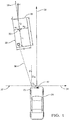
Figure 1 diagrammatically illustrates an example use of a system for tracking a detected object according to an embodiment of this invention. -
Figure 2 schematically illustrates selected portions of an example embodiment of a system for tracking an object designed according to an embodiment of this invention. -
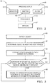
Figure 3 is a flowchart diagram summarizing an example method of classifying a stationary or slowly moving object. -
Figure 1 diagrammatically illustrates asystem 20 for tracking anobject 22. In this example, thesystem 20 comprises atracking device 40 situated on ahost vehicle 24. In one embodiment, thehost vehicle 24 is an autonomous or semi-autonomous vehicle. Thesystem 20 determines information about theobject 22, and continuously updates the information about theobject 22 over time. Thesystem 20 may "freeze," or stop updating, certain information about theobject 22 when particular conditions are met in order to maintain accurate information about theobject 22. - The
system 20 uses known radar signaling as schematically shown at 26 for detecting several characteristics of theobject 22. In an example, thesystem 20 includes four short range radar detectors, and a forward looking radar detector. Thesystem 20 determines characteristics of theobject 22 based on the detections it receives and any known information, such as the position and speed of thesystem 20. - The
object 22 may be represented using a boundingbox 28 having acentroid 30. Tracking in two dimensions allows theobject 22 to be represented by arectangular bounding box 28. There are known tracking techniques for determining a boundingbox 28 corresponding to the edges of theobject 22 and for locating thecentroid 30 within that boundingbox 28. The boundingbox 28 is parameterized by a length L and a width W. The dimensions l1, l2, w1, and w2 indicate the position of thecentroid 30 relative to the edges of the body of theobject 22. The length L of the boundingbox 28 is equal to the sum of l1 and l2 and the width W is equal to the sum of w1 and w2. - The
host vehicle 24 has its own hostvehicle coordinate system 32, having alateral direction 34 and alongitudinal direction 36 relative to thehost vehicle 24. Thevehicle coordinate system 32 is positioned in a world coordinate system, which represents stationary ground. Each of the detections of thesystem 20 is in a frame of reference. The radar detectors of thesystem 20 each have a mounting position and boresight angle that are known with respect to thevehicle coordinate system 32. Generally, every detection generated by thesystem 20 can be characterized by a range (R), a range rate (Ṙ), and azimuth (θ). The speed of thehost vehicle 24, its orientation in the world, and the parameters in the radar frame of reference are used to compute a compensated range rate Ṙc for each detection. The compensated range rate Ṙc is a radial component of an over-the-ground velocity of theobject 22. -
Figure 2 schematically illustrates selected portions of thesystem 20. Atracking device 40 includes anemitter 42 anddetector 44. Theemitter 42 emits radiation in an outward direction and, when such radiation reflects off of an object (e.g., the object 22), that reflected radiation is received and detected by thedetector 44. In some example embodiments, theemitter 42 anddetector 44 operate according to known radar principles and techniques. Other embodiments include emitter and detector configurations that are useful for lidar or ultrasonic detection techniques. - The
tracking device 40 includes afilter 46 that is configured for estimating dynamic quantities of a trackedobject 22. In some example embodiments, thefilter 46 operates according to known principles of Kalman filters. A Kalman filter may estimate the position, heading angle, speed, curvature, acceleration, and yaw rate of theobject 22, for example. These quantities are referred to as the object's state variables. In some embodiments, thefilter 46 also estimates a length and width of theobject 22. - The
system 20 includes aprocessor 50, which may be a dedicated microprocessor or a portion of another computing device supported on thevehicle 24.Memory 52 is associated with theprocessor 50. In some example embodiments, thememory 52 includes computer-executable instructions that cause theprocessor 50 to operate for purposes of tracking a moving object and determining the pointing angle or body orientation angle of that object. In some example embodiments, thememory 52 at least temporarily contains information regarding various features or characteristics of a tracked object to facilitate theprocessor 50 making desired determinations regarding the pointing angle of such an object. - The
tracking filter 46 may provide an indication of thevelocity vector 38 of theobject 22, as shown inFigure 1 . Thevelocity vector 38 is expressed in terms of a Cartesian coordinate system, such as thevehicle coordinate system 32. In another embodiment, thevelocity vector 38 could be expressed in terms of the world coordinate system. In some cases, the world coordinate system and thevehicle coordinate system 32 are the same while in others there is a known relationship between those coordinate systems. In the illustrated example, longitudinal and lateral components u, v of thevelocity vector 38 are relative to thevehicle coordinate system 32. - The
tracking device 40 periodically updates and stores information about theobject 22. In one embodiment, thetracking filter 46 updates the object's state variables several times per second. In a further embodiment, thetracking device 40 updates the object's state variables more than 100 times per second. Thetracking device 40 predicts measurements at a particular time interval, then receives data from thedetector 44, and compares the predicted values with the measured values. Thefilter 46 generates a correction based on the difference between the predicted values and the measured values, and corrects the state variables based on the correction. - At each time interval, the
filter 46 predicts the object's state variables, then receives measurements of the object's state variables. Thefilter 46 compares the predicted state variables to the measured state variables and determines a correction to the state variables. In some embodiments, a length and width filter estimates an updated length and width of theobject 22 at each time step. - For stationary objects, radar sensors generate very few useful radar detections, and thus state variable estimates may have a large error. This is particularly true where both the
object 22 and thehost vehicle 24 are stationary. Many radar scatters can fall within the same range-Doppler bin, and the algorithms often used for determining the angles can resolve only a few angles in the same range-Doppler bin. Over time, the position of the detections can randomly vary on theobject 22, which may cause thetracking system 20 to incorrectly detect motion of theobject 22. -
Figure 3 summarizes an example method to help prevent thesystem 20 from detecting false motion of theobject 22. After anobject 22 is detected at 60, theprocessor 50 determines that theobject 22 is near thehost vehicle 24 at 62. In one example, near thehost vehicle 24 means that it is within the width of the road on which thehost vehicle 24 is located. For example, in the United States, a standard road lane is 3.7 meters, and thus two lane widths is about 7 meters. In one example, theprocessor 50 determines that theobject 22 is near thehost vehicle 24 if it is within about 10 meters of thehost vehicle 24. In other examples, near thehost vehicle 24 may mean less than about 10 meters or more than about 10 meters. Theprocessor 50 may determine whether theobject 22 is near thehost vehicle 24 by creating a rectangular region around thehost vehicle 24 and determining whether thecentroid 30 of theobject 22 is within that rectangular region. - The
processor 50 andfilter 46 estimate the object's state variables at 64 based on the detections at thedetector 44. In some embodiments, the determination and estimate at 62 and 64 may be done in reverse order or simultaneously. - The
processor 50 then determines whether the speed of thehost vehicle 24 is below a preselected host threshold and a speed of theobject 22 is below a preselected object threshold at 66. In one example, the preselected host threshold is selected to correspond to thehost vehicle 24 stopping or remaining stationary at a traffic light. In one example, the preselected object threshold is selected to indicate that the trackedobject 22 is stopped or stopping at a traffic light. If these conditions are not met, theprocessor 50 continues to update the object's state variables at 64. Once theprocessor 50 has determined that the conditions at 66 are satisfied, theprocessor 50 classifies the trackedobject 22 as stationary and "freezes" a position of theobject 22 relative to thehost vehicle 24 or stationary ground at 68. In this disclosure, the terms "frozen" or "freezing" correspond to theobject 22 being stationary. In one example embodiment, this "freezing" comprises setting a freeze flag as TRUE, and when the object is not frozen, the freeze flag is set to FALSE. This freezing of the object's position prevents thesystem 20 from detecting false motion due to the scattered detections when both thehost vehicle 24 and theobject 22 are stationary. - When the tracked
object 22 is classified as "frozen," theprocessor 50 stores some of the object's state variables, while thefilter 46 continues to periodically update other state variables, such as the object's speed, curvature, and yaw rate. In one embodiment, the position and orientation of the object are stored and not updated while the object is "frozen." In some embodiments, the lengths l1, l2 and widths w1, w2 will not be updated while the freeze flag is set to TRUE. - Once either the speed of the
host vehicle 24 exceeds the preselected host threshold or the velocity of theobject 22 exceeds the preselected object threshold, the position of theobject 22 will be unfrozen, or the freeze flag will be switched to FALSE. When the position of theobject 22 is unfrozen, thesystem 20 resumes updating all of the object's state variables periodically, including the position and orientation of theobject 22 at 64. - In some examples, this approach is only used for
objects 22 that have a velocity component (shown at u inFigure 1 ) that is parallel to thehost vehicle 24, or has a large component u in thelongitudinal direction 36.Objects 22 that do not have sufficient motion in thelongitudinal direction 36 relative to thehost vehicle 24 are difficult for thesystem 20 to determine when to switch the freeze flag to FALSE. - To determine when the
object 22 is moving again and thus classify theobject 22 as not frozen, thetracking device 40 uses range rates from the associated detections. Thetracking device 40 checks whether there are sufficient detections associated with theobject 22 whose azimuth θ has an absolute value of cosine that is above a preselected threshold. If there are sufficient detections that meet this criterion, then theprocessor 50 calculates the compensated range rate, as shown below. - In general, the raw range rate r from a radar detection can be modeled as:

object 22, and us and vs are the longitudinal and lateral velocities of thesensor system 20. In an example embodiment, the velocities u, v, us, vs are over the ground velocities in the vehicle coordinatesystem 32. The angle θ is the azimuth angle of the detection in the vehicle coordinatesystem 32. This equation can be rearranged to derive the compensated range rate as the object velocity projected onto the radial direction:
vehicle 24 and yaw rate signals as well as the sensor mounting location on thehost vehicle 24. Assuming that the over the ground lateral velocity v is less than a preselected threshold vmax and that the cosine of θ is positive, it follows that:
object 22 is moving. - If there are not sufficient detections that meet the criterion requiring cosine of θ be above a threshold, then the
processor 50 determines the sensor velocities us, vs by comparing the compensated range rate to a threshold. If the biggest absolute value of compensated range rate ṙcomp of associated detections of theobject 22 exceeds a preselected threshold smax, then the object is classified as moving, and thesystem 20 treats theobject 22 as unfrozen. - When the
object 22 is not frozen, all of the object's state variables may be updated at every time step. Thesystem 20 continually emits radiation, detects reflected radiation, and estimates values based on those detections. Theprocessor 50 may repeat many of the steps represented inFigure 3 in an iterative fashion while thehost vehicle 24 is in operation or in some embodiments, only when thehost vehicle 24 is travelling at speeds below the preselected host speed threshold. - The preceding description is exemplary rather than limiting in nature. Variations and modifications to the disclosed examples may become apparent to those skilled in the art that do not necessarily depart from the essence of this invention. The scope of legal protection given to this invention can only be determined by studying the following claims.
Claims (15)
- A method of tracking a detected object (22), the method comprising:determining that a tracked object (22) is near a host vehicle (24);determining an estimated velocity of the tracked object (22); andclassifying the tracked object (22) as frozen relative to stationary ground when the estimated velocity is below a preselected object threshold and a speed of the host vehicle (24) is below a preselected host threshold.
- The method of claim 1, wherein classifying the tracked object (22) as frozen comprises freezing a determined orientation, length, width, and centroid position of the tracked object (22) with respect to stationary ground.
- The method of claim 1 or 2, wherein when the tracked object (22) is classified as frozen, periodically updating an estimate of speed, curvature, and yaw rate for the tracked object (22).
- The method of claim 3, comprising estimating the speed, curvature, yaw rate, and position of the object (22) using a Kalman filter.
- The method of any of claims 1 - 4, comprising
classifying the tracked object (22) as not frozen when the speed of the host vehicle (24) exceeds the preselected host threshold or the estimated velocity of the tracked object (22) exceeds the preselected object threshold. - The method of any of claims 1 - 5, wherein the object (22) is a second vehicle (22), and the second vehicle (22) is oriented in a direction parallel to the host vehicle (24).
- The method of any of claims 1 - 6, wherein the estimated velocity of the object (22) is a velocity relative to the host vehicle (24).
- The method of any of claims 1-7, wherein the preselected host threshold is equal to the preselected object threshold.
- A system for tracking a detected object, the system comprising:a tracking device (40) configured to detect an object (22); anda processor (50) configured to:determine that the tracked object (22) is near a host vehicle (24);determine an estimated velocity of the tracked object (22); andclassify the tracked object (22) as frozen relative to stationary ground when the estimated velocity is below a preselected object threshold and a speed of the host vehicle (24) is below a preselected host threshold.
- The system of claim 9, wherein the processor (50) is configured to freeze a determined orientation, length, width, and centroid position of the tracked object (22) with respect to stationary ground.
- The system of claim 9 or 10, wherein the processor (50) is configured to periodically update an estimate of speed, curvature, and yaw rate for the tracked object (22) when the tracked object (22) is classified as frozen.
- The system of any of claims 9 - 11, wherein the processor (50) is configured to:
classify the tracked object (22) as not frozen when the speed of the host vehicle (24) exceeds the preselected host threshold or the estimated velocity of the tracked object exceeds the preselected object threshold. - The system of any of claims 9 - 12, wherein the object (22) is a second vehicle and the second vehicle (22) is oriented in a direction parallel to the host vehicle (24).
- The system of any of claims 9 - 13, wherein the estimated velocity of the object (22) is a velocity relative to the host vehicle (24).
- The system of any of claims 9 - 14, wherein the preselected host threshold is equal to the preselected object threshold.
Applications Claiming Priority (1)
| Application Number | Priority Date | Filing Date | Title |
|---|---|---|---|
| US16/106,308 US10914813B2 (en) | 2018-08-21 | 2018-08-21 | Classifying potentially stationary objects tracked by radar |
Publications (1)
| Publication Number | Publication Date |
|---|---|
| EP3614302A1 true EP3614302A1 (en) | 2020-02-26 |
Family
ID=67402853
Family Applications (1)
| Application Number | Title | Priority Date | Filing Date |
|---|---|---|---|
| EP19186755.5A Pending EP3614302A1 (en) | 2018-08-21 | 2019-07-17 | Classifying potentially stationary objects tracked by radar |
Country Status (3)
| Country | Link |
|---|---|
| US (1) | US10914813B2 (en) |
| EP (1) | EP3614302A1 (en) |
| CN (1) | CN110888115B (en) |
Cited By (3)
| Publication number | Priority date | Publication date | Assignee | Title |
|---|---|---|---|---|
| CN114578342A (en) * | 2022-02-25 | 2022-06-03 | 森思泰克河北科技有限公司 | Target tracking method for vehicle-mounted radar, vehicle-mounted radar and storage medium |
| EP4350385A1 (en) * | 2022-10-07 | 2024-04-10 | Aptiv Technologies Limited | Stationary object detection and classification based on low-level radar data |
| US12307353B2 (en) | 2021-04-14 | 2025-05-20 | Aptiv Technologies AG | Radar system using a machine-learned model for stationary object detection |
Families Citing this family (4)
| Publication number | Priority date | Publication date | Assignee | Title |
|---|---|---|---|---|
| US11110895B2 (en) * | 2018-04-09 | 2021-09-07 | Cisco Technology, Inc. | Vehicle network intrusion detection system (IDS) using vehicle state predictions |
| US11787407B2 (en) * | 2019-07-24 | 2023-10-17 | Pony Ai Inc. | System and method for sensing vehicles and street |
| EP4012347B1 (en) * | 2020-12-14 | 2025-01-29 | Aptiv Technologies AG | System and method for mapping a vehicle environment |
| US12169238B2 (en) | 2021-09-22 | 2024-12-17 | Ford Global Technologies, Llc | Enhanced radar recognition for automated vehicles |
Citations (1)
| Publication number | Priority date | Publication date | Assignee | Title |
|---|---|---|---|---|
| US20090278672A1 (en) * | 2005-04-15 | 2009-11-12 | Michael Weilkes | Driver assistance system having a device for recognizing stationary objects |
Family Cites Families (21)
| Publication number | Priority date | Publication date | Assignee | Title |
|---|---|---|---|---|
| FR2817527B1 (en) * | 2000-12-04 | 2003-01-10 | Alstom | METHOD AND DEVICE FOR LOCATING A VEHICLE ON A TRACK |
| AUPS123702A0 (en) * | 2002-03-22 | 2002-04-18 | Nahla, Ibrahim S. Mr | The train navigtion and control system (TNCS) for multiple tracks |
| JP4823520B2 (en) * | 2002-07-15 | 2011-11-24 | オートモーティブ システムズ ラボラトリー インコーポレーテッド | How to estimate the state of a target vehicle on the road |
| US7457692B2 (en) * | 2004-10-12 | 2008-11-25 | Ford Global Technologies Llc | Occupant classification sensor calibration system |
| US8447472B2 (en) * | 2007-01-16 | 2013-05-21 | Ford Global Technologies, Llc | Method and system for impact time and velocity prediction |
| EP2085279B1 (en) * | 2008-01-29 | 2011-05-25 | Ford Global Technologies, LLC | A system for collision course prediction |
| US8260539B2 (en) * | 2010-05-12 | 2012-09-04 | GM Global Technology Operations LLC | Object and vehicle detection and tracking using 3-D laser rangefinder |
| CN101881615B (en) * | 2010-05-28 | 2012-07-11 | 清华大学 | Method for detecting visual barrier for driving safety |
| CN102013668B (en) * | 2010-11-29 | 2013-10-30 | 山东科技大学 | Method for implementing overload inverse-time protection of alternating-current motor |
| US10008002B2 (en) * | 2012-02-28 | 2018-06-26 | NXP Canada, Inc. | Single-camera distance estimation |
| DE102012107444B3 (en) * | 2012-08-14 | 2013-03-07 | Jenoptik Robot Gmbh | Method for classifying traveling vehicles e.g. passenger car, by tracking vehicle position magnitude in flowing traffic, involves comparing discontinuity portion length with stored typical velocity-normalized lengths to classify vehicle |
| US8862394B2 (en) * | 2013-01-22 | 2014-10-14 | Ensco, Inc. | System and method for tracking and locating a person, animal, or machine |
| US9255988B2 (en) * | 2014-01-16 | 2016-02-09 | GM Global Technology Operations LLC | Object fusion system of multiple radar imaging sensors |
| US9834207B2 (en) * | 2014-04-15 | 2017-12-05 | GM Global Technology Operations LLC | Method and system for detecting, tracking and estimating stationary roadside objects |
| CN105216792A (en) * | 2014-06-12 | 2016-01-06 | 株式会社日立制作所 | Obstacle target in surrounding environment is carried out to the method and apparatus of recognition and tracking |
| CN104101878B (en) * | 2014-06-23 | 2017-02-15 | 北京智行者科技有限公司 | Vehicle front target recognition system and recognition method |
| EP3173975A1 (en) * | 2015-11-30 | 2017-05-31 | Delphi Technologies, Inc. | Method for identification of candidate points as possible characteristic points of a calibration pattern within an image of the calibration pattern |
| EP3174007A1 (en) * | 2015-11-30 | 2017-05-31 | Delphi Technologies, Inc. | Method for calibrating the orientation of a camera mounted to a vehicle |
| CN106990399B (en) * | 2017-05-11 | 2019-12-20 | 西安电子科技大学 | Networking radar system power and bandwidth joint distribution method for target tracking |
| GB201804195D0 (en) * | 2018-03-15 | 2018-05-02 | Blue Vision Labs Uk Ltd | Visual vehicle tracking through noise and occlusions using crowd-sourced maps |
| US11435479B2 (en) * | 2018-08-06 | 2022-09-06 | Luminar, Llc | Determining relative velocity based on an expected configuration |
-
2018
- 2018-08-21 US US16/106,308 patent/US10914813B2/en active Active
-
2019
- 2019-07-17 EP EP19186755.5A patent/EP3614302A1/en active Pending
- 2019-08-19 CN CN201910763339.XA patent/CN110888115B/en active Active
Patent Citations (1)
| Publication number | Priority date | Publication date | Assignee | Title |
|---|---|---|---|---|
| US20090278672A1 (en) * | 2005-04-15 | 2009-11-12 | Michael Weilkes | Driver assistance system having a device for recognizing stationary objects |
Non-Patent Citations (3)
| Title |
|---|
| DARMS M S ET AL: "Obstacle Detection and Tracking for the Urban Challenge", IEEE TRANSACTIONS ON INTELLIGENT TRANSPORTATION SYSTEMS, IEEE, PISCATAWAY, NJ, USA, vol. 10, no. 3, 1 September 2009 (2009-09-01), pages 475 - 485, XP011347184, ISSN: 1524-9050, DOI: 10.1109/TITS.2009.2018319 * |
| KAEMPCHEN N ET AL: "IMM object tracking for high dynamic driving maneuvers", INTELLIGENT VEHICLES SYMPOSIUM, 2004 IEEE PARMA, ITALY JUNE 14-17, 2004, 14 June 2004 (2004-06-14), pages 825 - 830, XP010727754, ISBN: 978-0-7803-8310-4, DOI: 10.1109/IVS.2004.1336491 * |
| STEYER SASCHA ET AL: "Object tracking based on evidential dynamic occupancy grids in urban environments", 2017 IEEE INTELLIGENT VEHICLES SYMPOSIUM (IV), IEEE, 11 June 2017 (2017-06-11), pages 1064 - 1070, XP033133884, DOI: 10.1109/IVS.2017.7995855 * |
Cited By (4)
| Publication number | Priority date | Publication date | Assignee | Title |
|---|---|---|---|---|
| US12307353B2 (en) | 2021-04-14 | 2025-05-20 | Aptiv Technologies AG | Radar system using a machine-learned model for stationary object detection |
| CN114578342A (en) * | 2022-02-25 | 2022-06-03 | 森思泰克河北科技有限公司 | Target tracking method for vehicle-mounted radar, vehicle-mounted radar and storage medium |
| EP4350385A1 (en) * | 2022-10-07 | 2024-04-10 | Aptiv Technologies Limited | Stationary object detection and classification based on low-level radar data |
| US12360240B2 (en) | 2022-10-07 | 2025-07-15 | Aptiv Technologies AG | Stationary object detection and classification based on low-level radar data |
Also Published As
| Publication number | Publication date |
|---|---|
| US10914813B2 (en) | 2021-02-09 |
| US20200064436A1 (en) | 2020-02-27 |
| CN110888115A (en) | 2020-03-17 |
| CN110888115B (en) | 2023-12-29 |
Similar Documents
| Publication | Publication Date | Title |
|---|---|---|
| US10914813B2 (en) | Classifying potentially stationary objects tracked by radar | |
| EP3151034B1 (en) | Automated vehicle radar system to determine yaw-rate of a target vehicle | |
| EP3486132B1 (en) | Vehicle control device | |
| US20150239472A1 (en) | Vehicle-installed obstacle detection apparatus having function for judging motion condition of detected object | |
| EP1367411B1 (en) | Collision detection system and method of estimating miss distance | |
| US20070043502A1 (en) | System for and method of detecting a collision and predicting a vehicle path | |
| US20110025548A1 (en) | System and method for vehicle sensor fusion | |
| US20040012516A1 (en) | Tracking system and method employing multiple overlapping sensors | |
| EP2787367A1 (en) | Method of operating a radar system to reduce nuisance alerts caused by false stationary targets | |
| EP3896672A1 (en) | Other vehicle motion prediction method and other vehicle motion prediction device | |
| CN107103275B (en) | Wheel-based vehicle detection and tracking using radar and vision | |
| EP1537440B1 (en) | Road curvature estimation and automotive target state estimation system | |
| EP3598169A1 (en) | Radar based tracking of slow moving objects | |
| US9689975B2 (en) | Radar apparatus | |
| EP4155150B1 (en) | Self-learning-based interpretation of driver's intent for evasive steering | |
| EP3537174A1 (en) | Method and system for determining the pointing angle of a moving object | |
| US11279350B2 (en) | Method of adaptive trajectory generation for a vehicle | |
| US10571563B2 (en) | Radar device and signal processing method | |
| CN110723144A (en) | Lane distribution system | |
| US11169259B2 (en) | Method and surroundings detection device for determining the presence and/or properties of one or multiple objects in the surroundings of a motor vehicle | |
| CN110678776B (en) | System for enhanced object tracking | |
| JP6906638B2 (en) | Vehicle system for detecting oncoming vehicles | |
| CN110678778B (en) | Vehicle system for detecting an oncoming vehicle | |
| EP4564308A1 (en) | Method and system for tracking an object in a field of view of a host vehicle | |
| US20260023382A1 (en) | Device and method for creating dynamic occupancy grid map |
Legal Events
| Date | Code | Title | Description |
|---|---|---|---|
| PUAI | Public reference made under article 153(3) epc to a published international application that has entered the european phase |
Free format text: ORIGINAL CODE: 0009012 |
|
| STAA | Information on the status of an ep patent application or granted ep patent |
Free format text: STATUS: THE APPLICATION HAS BEEN PUBLISHED |
|
| AK | Designated contracting states |
Kind code of ref document: A1 Designated state(s): AL AT BE BG CH CY CZ DE DK EE ES FI FR GB GR HR HU IE IS IT LI LT LU LV MC MK MT NL NO PL PT RO RS SE SI SK SM TR |
|
| AX | Request for extension of the european patent |
Extension state: BA ME |
|
| RIN1 | Information on inventor provided before grant (corrected) |
Inventor name: SCHIFFMANN, FRANZ P. Inventor name: NAGARAJA, KEERTHI RAJ Inventor name: VISHWAJEET, KUMAR Inventor name: SCHIFFMANN, JAN K. Inventor name: DANG, WENBING |
|
| STAA | Information on the status of an ep patent application or granted ep patent |
Free format text: STATUS: REQUEST FOR EXAMINATION WAS MADE |
|
| 17P | Request for examination filed |
Effective date: 20200702 |
|
| RBV | Designated contracting states (corrected) |
Designated state(s): AL AT BE BG CH CY CZ DE DK EE ES FI FR GB GR HR HU IE IS IT LI LT LU LV MC MK MT NL NO PL PT RO RS SE SI SK SM TR |
|
| STAA | Information on the status of an ep patent application or granted ep patent |
Free format text: STATUS: EXAMINATION IS IN PROGRESS |
|
| 17Q | First examination report despatched |
Effective date: 20211117 |
|
| RAP3 | Party data changed (applicant data changed or rights of an application transferred) |
Owner name: APTIV TECHNOLOGIES LIMITED |
|
| RAP1 | Party data changed (applicant data changed or rights of an application transferred) |
Owner name: APTIV TECHNOLOGIES AG |
|
| RAP3 | Party data changed (applicant data changed or rights of an application transferred) |
Owner name: APTIV TECHNOLOGIES AG |