EP3614215A1 - Transmission device, transmission method, reception device, and reception method - Google Patents
Transmission device, transmission method, reception device, and reception method Download PDFInfo
- Publication number
- EP3614215A1 EP3614215A1 EP18770377.2A EP18770377A EP3614215A1 EP 3614215 A1 EP3614215 A1 EP 3614215A1 EP 18770377 A EP18770377 A EP 18770377A EP 3614215 A1 EP3614215 A1 EP 3614215A1
- Authority
- EP
- European Patent Office
- Prior art keywords
- transmission
- reception
- section
- signal
- information
- Prior art date
- Legal status (The legal status is an assumption and is not a legal conclusion. Google has not performed a legal analysis and makes no representation as to the accuracy of the status listed.)
- Pending
Links
Images





Classifications
-
- G—PHYSICS
- G04—HOROLOGY
- G04R—RADIO-CONTROLLED TIME-PIECES
- G04R20/00—Setting the time according to the time information carried or implied by the radio signal
- G04R20/02—Setting the time according to the time information carried or implied by the radio signal the radio signal being sent by a satellite, e.g. GPS
Definitions
- the present technologies relate to a transmission apparatus and transmission method and a reception apparatus and reception method, and more particularly, to a transmission apparatus and reception method and a reception apparatus and reception method that can suppress reduction in communication quality.
- Frequency division multiplexing FDM
- time division multiplexing TDM
- spread spectrum and so on have been available to date as signal multiplexing methods (refer, for example, to PTL 1).
- a chirp modulation method of a phase modulated signal has been devised as a transmission signal modulation scheme (refer, for example, to PTL 2).
- More accurate frequency control and time-of-day control are required to achieve multiplexing of a larger number of signals using these schemes. For this reason, use of a GNSS signal for achieving such control has been devised.
- GNSS signals are not always received properly. Not only in the case where GNSS signals cannot be received but also in the case where the received GNSS signals are of low quality, error in time-of-day information or frequency information generated has increased due, for example, to the use of an interpolation formula, possibly resulting in reduced communication quality.
- the present disclosure has been devised in light of the above circumstances, and it is an object of the present disclosure to suppress reduction in communication quality.
- a transmission apparatus of an aspect of the present technology includes: a setting section adapted to set information for controlling transmission of a transmission signal on the basis of a GNSS signal or an oscillation frequency of an oscillator; a transmission control section adapted to control the transmission of the transmission signal on a basis of the information set by the setting section; and a transmission section adapted to send the transmission signal under control of the transmission control section.
- the setting section can select the GNSS signal or the oscillation frequency in accordance with a reception status of the GNSS signal and set the information by using the selected option.
- the setting section can set the information by using the GNSS signal, and in the case where the received GNSS signal has a lower quality than the criterion, the setting section can set the information by using the oscillation frequency.
- the information includes time-of-day information
- the setting section can be configured such that in the case where the received GNSS signal has a higher quality than a given criterion, the setting section sets time of day acquired from the GNSS signal as the time-of-day information and that in the case where the received GNSS signal has a lower quality than the criterion, the setting section sets time of day acquired by counting at timings synchronous with the oscillation frequency as the time-of-day information.
- the transmission control section can control the transmission section to send the transmission signal to a predetermined receiving side at a known transmission timing on the basis of the time-of-day information set by the setting section.
- the setting section can correct the time of day acquired by counting at timings synchronous with the oscillation frequency by using time of day acquired from the GNSS signal.
- the information includes a transmission control frequency
- the setting section can be configured such that in the case where the received GNSS signal has a higher quality than a given criterion, the setting section corrects the oscillation frequency by using a frequency acquired from the GNSS signal received this time and sets the corrected oscillation frequency as the transmission control frequency and that in the case where the received GNSS signal has a lower quality than the criterion, the setting section corrects the oscillation frequency with a previous correction value and sets the corrected oscillation frequency as the transmission control frequency.
- the transmission control section can control the transmission section to send the transmission signal at a transmission frequency based on the transmission control frequency set by the setting section.
- the transmission apparatus further includes a GNSS reception section that receives the GNSS signal, and the setting section can be configured to set the information on the basis of the GNSS signal received by the GNSS reception section or the oscillation frequency.
- a transmission method of an aspect of the present technology is a transmission method including: setting information for controlling transmission of a transmission signal on the basis of a GNSS signal or an oscillation frequency of an oscillator; controlling the transmission of the transmission signal on the basis of the set information; and sending the transmission signal in accordance with the transmission control.
- a reception apparatus of another aspect of the present technology includes a setting section adapted to set information for controlling reception of a signal sent from a transmitting side on a basis of a GNSS signal or an oscillation frequency of an oscillator; a reception control section adapted to control the reception of the signal on the basis of the information set by the setting section; and a reception section adapted to receive the signal under control of the reception control section.
- the setting section can select the GNSS signal or the oscillation frequency in accordance with a reception status of the GNSS signal and set the information by using the selected option.
- the setting section can set the information by using the GNSS signal, and in the case where the received GNSS signal has a lower quality than the criterion, the setting section can set the information by using the oscillation frequency.
- the information includes time-of-day information
- the setting section can be configured such that in the case where the received GNSS signal has a higher quality than a given criterion, the setting section sets time of day acquired from the GNSS signal as the time-of-day information and that in the case where the received GNSS signal has a lower quality than the criterion, the setting section sets time of day acquired by counting at timings synchronous with the oscillation frequency as the time-of-day information.
- the reception control section can control the reception section to receive the signal from a predetermined transmitting side at a known reception timing on the basis of the time-of-day information set by the setting section.
- the setting section can correct the time of day acquired by counting at timings synchronous with the oscillation frequency by using time of day acquired from the GNSS signal.
- the information includes a reception control frequency
- the setting section can be configured such that in the case where the received GNSS signal has a higher quality than a given criterion, the setting section corrects the oscillation frequency by using a frequency acquired from the GNSS signal received this time and sets the corrected oscillation frequency as the reception control frequency and that in the case where the received GNSS signal has a lower quality than the criterion, the setting section corrects the oscillation frequency with a previous correction value and sets the corrected oscillation frequency as the reception control frequency.
- the reception control section can control the reception section to receive the signal at a reception frequency based on the reception control frequency set by the setting section.
- the reception apparatus further includes a GNSS reception section that receives the GNSS signal, and the setting section can be configured to set the information on the basis of the GNSS signal received by the GNSS reception section or the oscillation frequency.
- a reception method of another aspect of the present technology sets information for controlling reception of a signal sent from a transmitting side on the basis of a GNSS signal or an oscillation frequency of an oscillator, controls the reception of the signal on the basis of the set information, and receives the signal in accordance with the reception control.
- information for controlling transmission of a transmission signal is set on the basis of a GNSS signal or an oscillation frequency of an oscillator, the transmission of the transmission signal is controlled on the basis of the set information, and the transmission signal is sent in accordance with the transmission control.
- information for controlling reception of a signal sent from a transmitting side is set on the basis of a GNSS signal or an oscillation frequency of an oscillator, the reception of the signal is controlled on the basis of the set information, and the signal is received in accordance with the reception control.
- the present technologies permit transmission or reception of signals.
- the present technologies also permit suppression of reduction in communication quality.
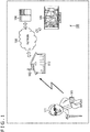
- FIG. 1 is a diagram illustrating a main configuration example of a position notification system, an embodiment of a signal transmission/reception system to which the present technology is applied.
- a position notification system 100 illustrated in FIG. 1 allows a transmission apparatus 101 to notify its own position.
- the position notification system 100 is used, for example, to monitor and manage the position of a subject.
- the position notification system 100 includes devices such as the transmission apparatus 101, a high sensitivity reception apparatus 102, a server 104, a terminal apparatus 105, and so on.
- the number of each of the transmission apparatus 101, the high sensitivity reception apparatus 102, the server 104, and the terminal apparatus 105 is arbitrary, and there may be two or more of each thereof.
- the transmission apparatus 101 is an embodiment of a transmission apparatus to which the present technology is applied and sends, for example, identification information identifying itself, position information indicating the position thereof, and other information as a radio signal.
- the high sensitivity reception apparatus 102 is an embodiment of a reception apparatus to which the present technology is applied and acquires identification information, position information, and other information of the transmission apparatus 101 by receiving the radio signal and supplies these pieces of information to the server 104 via the network 103.
- the high sensitivity reception apparatus 102 functions as a relay station that relays information sent from the transmission apparatus 101 to the server 104.
- the server 104 manages the position of each of the transmission apparatuses 101 by managing identification information in association with position information.
- the terminal apparatus 105 operated by a user wishing to find out the position of the transmission apparatus 101 accesses the server 104 via the network 103 and requests the position information of the desired transmission apparatus 101 by supplying the identification information of the transmission apparatus 101.
- the server 104 supplies the requested position information corresponding to the identification information to the terminal apparatus 105.
- the terminal apparatus 105 acquires the position information and notifies the user of the position of the transmission apparatus 101, for example, by displaying the position information together with map data.
- the server 104 can indirectly manage the position of a subject whose position is to be monitored (managed) by causing the transmission apparatus 101 as described above to be carried (including held, worn, or the like) by the subject whose position is desirably monitored (managed).
- the user monitors the position of an elderly 111 and causes the elderly 111 to carry the transmission apparatus 101.
- the position of the transmission apparatus 101 is managed by the server 104 and supplied to the terminal apparatus 105. This allows the user to find out the position of the elderly 111 who is carrying the transmission apparatus 101 by operating the terminal apparatus 105.
- the position of an arbitrary subject is monitored.
- the subject may be a child or an animal such as dog or cat, or a company employee.
- the transmission apparatus 101 may be built into a mobile information processing apparatus such as mobile phone or smartphone.
- Position information of the transmission apparatus 101 may be information of any kind and generated in any way as long as this information indicates the position of the transmission apparatus 101.
- the transmission apparatus 101 may receive a GNSS (Global Navigation Satellite System) signal from a GNSS satellite and find its own position information (e.g., longitude and latitude) on the basis of the GNSS signal.
- the transmission apparatus 101 may identify its own position by using a dedicated position identification system other than the GNSS.
- this position information may be generated by an apparatus other than the transmission apparatus 101 such as the high sensitivity reception apparatus 102, the server 104, or a dedicated information processing apparatus (e.g., server) provided separately.
- the transmission apparatus 101 may supply a received GNSS signal to other apparatus such that the other apparatus finds the position information of the transmission apparatus 101 from the GNSS signal.
- the transmission apparatus 101 may supply, to other apparatus, information acquired by using a dedicated position identification system other than the GNSS such that the other apparatus finds position information of the transmission apparatus 101 on the basis of that information.
- the other apparatus may find position information of the transmission apparatus 101 on the basis of a status of communication between the transmission apparatus 101 and the high sensitivity reception apparatus 102. For example, the fact that the transmission apparatus 101 is located within a communication range of the high sensitivity reception apparatus 102 may be identified by identifying the high sensitivity reception apparatus 102 that received a signal from the transmission apparatus 101.
- position information of the transmission apparatus 101 may be found on the basis of intensity or delay time of a reception signal received by the high sensitivity reception apparatus 102, or other factors. Also, for example, position information of the transmission apparatus 101 may be found by trigonometry by using position information of the plurality of high sensitivity reception apparatuses 102 that received a signal from the transmission apparatus 101.
- the high sensitivity reception apparatus 102 is installed at an arbitrary position.
- the high sensitivity reception apparatus 102 may be installed on a roof, a rooftop, or other position of a structure 112 such as building, apartment complex, or house.
- the structure 112 is suitable because of its abundance in urban areas where the subject carrying the transmission apparatus 101 and whose position is to be monitored (e.g., elderly 111) is highly likely to be active and because of its ease for installation.
- the subject whose position is to be monitored the subject whose position is to be monitored is human
- the home of the subject whose position is to be monitored is suitable because the subject whose position is to be monitored is highly likely in the vicinity.
- the high sensitivity reception apparatus 102 may be installed, for example, on an automobile, motorcycle, bicycle, or other movable body (also referred to as a moving body). That is, the position of the high sensitivity reception apparatus 102 may vary.
- the network 103 is an arbitrary communication network and may be a wired or wireless communication network or may include a combination of both networks. Also, the network 103 may include a single communication network or a plurality of communication networks.
- the network 103 may include the Internet, a public telephone network, wireless mobile wide area communication networks such as so-called 3G and 4G lines, wireless communication networks for communication compliant with WAN (Wide Area Network), LAN (Local Area Network), and Bluetooth (registered trademark) standards, communication channel for short range wireless communication such as NFC (Near Field Communication), communication channel for infrared communication, communication networks for wired communication compliant with HDMI (registered trademark) (High-Definition Multimedia Interface) and USB (Universal Serial Bus), and communication networks and channels of arbitrary communication standards.
- WAN Wide Area Network
- LAN Local Area Network
- Bluetooth registered trademark
- communication channel for short range wireless communication such as NFC (Near Field Communication), communication channel for infrared communication
- HDMI registered trademark
- USB Universal Serial Bus
- the server 104 and the terminal apparatus 105 are information processing apparatuses for processing information.
- the server 104 and the terminal apparatus 105 are connected to the network 103 in such a manner as to permit communication. This allows the server 104 and the terminal apparatus 105 to communicate with other communication apparatuses connected to the network 103 via the network 103.
- the server 104 manages the position of each of the transmission apparatuses 101. Also, the server 104 can manage users to whom the provision of position information of the transmission apparatus 101 is permitted. For example, the server 104 can provide position information of each of the transmission apparatuses 101 only to the users who are permitted to acquire position information of that transmission apparatus 101.
- the server 104 can manage the position of that transmission apparatus 101.
- the server 104 can no longer manage the position thereof. Therefore, the wider the network of the communication range between the high sensitivity reception apparatus 102 and the transmission apparatus 101 spreads, the more accurately the server 104 can manage the position of the transmission apparatus 101.
- the term "more accurate management” refers to management of the position of the transmission apparatus 101 in a wider range (i.e., reduce a region where the position of the transmission apparatus 101 cannot be managed).
- the farther the transmission apparatus 101 and the high sensitivity reception apparatus 102 can send and receive radio signals the better.
- the transmission apparatus 101 and the high sensitivity reception apparatus 102 exchange radio signals in an arbitrary manner and may comply with any communication standard.
- the transmission apparatus 101 and the high sensitivity reception apparatus 102 may exchange radio signals by a method that permits long distance communication by using a frequency band including 925 MHz (also referred to as a 920-MHz band).
- the high sensitivity reception apparatus 102 detects a radio signal at that known time and frequency, thus making detection easier.
- This provides improved reception sensitivity.
- the communication range of the high sensitivity reception apparatus 102 can be expanded. It should be noted that a decline in accuracy for controlling the time and frequency as described above makes the detection more difficult, possibly resulting in reduced reception sensitivity. In other words, the reception sensitivity can be improved by improving the accuracy for controlling the time and frequency.
- the single high sensitivity reception apparatus 102 receives radio signals from the plurality of transmission apparatuses 101 (transmission apparatuses 101-1 to 101-N) as illustrated in FIG. 2 .
- Frequency division multiplexing (FDM), time division multiplexing (TDM), spread spectrum, and so on have been available as conventional multiplexing methods as recited, for example, in PTL 1.
- a chirp modulation method of a phase-modulated signal was devised as a modulation scheme of a transmission signal as recited, for example, in PTL 2.
- the larger the communication range the larger the number (N) of transmission apparatuses 101 as illustrated in FIG. 2 , thus requiring multiplexing of a larger number of signals.
- N the number of transmission apparatuses 101 as illustrated in FIG. 2 .
- signals need to be multiplexed in such a manner as to prevent mixing of the signals. More specifically, in order to multiplex a larger number of signals, time and frequency must be controlled with accuracy (more elaborately) to prevent mixing of the signals. In other words, a larger number of signals can be multiplexed by improving the accuracy for controlling the time and frequency.
- the GNSS Global Navigation Satellite System
- the GNSS Global Navigation Satellite System
- a GNSS signal is a navigation signal sent from the navigation satellite.
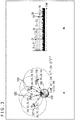
- a receiver on earth 120 receives GNSS signals from four navigation satellites (navigation satellites 121 to 124) to measure its position on the basis of the SNSS signal as illustrated in FIG. 3A .
- the position of the navigation satellite 121 is denoted as (X1, Y1, Z1), and a satellite time of day thereof is denoted as T1.
- the position of the navigation satellite 122 is denoted as (X2, Y2, Z2), and the satellite time of day thereof is denoted as T2.
- the position of the navigation satellite 123 is denoted as (X3, Y3, Z3), and the satellite time of day thereof is denoted as T3.
- the position of the navigation satellite 124 is denoted as (X4, Y4, Z4), and the satellite time of day thereof is denoted as T4. Then, the position of the receiver is denoted as (Xu, Yu, Zu), and a receiver time of day thereof is denoted as Tu.
- the receiver calculates its own position from synchronization information of a spreading code (C/A code) of the GNSS signal. For example, we assume that the receiver received a GNSS signal S1 of the navigation satellite 121, a GNSS signal S2 of the navigation satellite 122, a GNSS signal S3 of the navigation satellite 123, and a GNSS signal S4 of the navigation satellite 124 at times of day as illustrated in FIG. 3B .
- a spreading code C/A code
- the relationship between the reception times of day of the respective GNSS signals can be represented by times of day T1, T2, T3, T4, and Tu, and, for example, letting a speed of light be denoted as C, simultaneous equations as illustrated in formulas (1) through (4) hold:
- the receiver position (Xu, Yu, Zu) and the receiver time of day Tu can be found by solving the simultaneous equations as given above. In other words, the receiver position and the receiver time of day can be found if the GNSS signals can be received from four or more navigation satellites with sufficient quality.
- time-of-day information (receiver time of day) acquired by a receiver on the basis of GNSS signals as described above is more accurate than time-of-day information acquired by using the oscillator incorporated in the receiver.
- information acquired from GNSS signals includes advance information for correcting 'leap seconds.
- the receiver can acquire more accurate time-of-day information by inserting 'leap seconds' on the basis of this information.
- GNSS signals are not always received properly.
- the receiver position (Xu, Yu, Zu) and the receiver time of day Tu also deteriorate in accuracy.
- a decline in time-of-day control accuracy may cause mixing of signals during time division multiplexing and reduced reception sensitivity due to increased error in signal transmission and reception times of day, possibly resulting in reduced communication quality.
- information for controlling transmission of a transmission signal is set on the basis of the GNSS signal or the oscillation frequency of the oscillator, the transmission of the transmission signal is controlled on the basis of the set information, and the transmission signal is sent in accordance with the transmission control. This suppresses reduction in time-of-day control accuracy, thus suppressing reduction in communication quality.
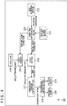
- FIG. 4 is a block diagram illustrating a main configuration example of the transmission apparatus 101.
- the transmission apparatus 101 includes a criterion setting section 211, a GNSS reception section 212, a correction determination section 213, an oscillator 214, a clock counter 215, a clock section 216, a transmission schedule control section 217, a transmission control section 218, an oscillation section 219, and a transmission section 220.
- the criterion setting section 211 performs a process related to setting of a criterion related to determination regarding transmission time-of-day control.
- the criterion setting section 211 can be realized by arbitrary components.
- the criterion setting section 211 may include a circuit, an LSI (Large Scale Integration), a system LSI, a processor, a module, a unit, a set, a device, an apparatus, a system, or the like. Alternatively, a plurality thereof may be used in combination.
- the criterion setting section 211 may include a CPU and a memory, and the CPU (Central Processing Unit) performs the above process by executing a program using the memory.
- CPU Central Processing Unit
- the GNSS reception section 212 performs a process related to reception of a GNSS signal.
- the GNSS reception section 212 can be realized by arbitrary components.
- the GNSS reception section 212 may include a circuit, an LSI, a system LSI, a processor, a module, a unit, a set, a device, an apparatus, a system, or the like.
- a plurality thereof may be used in combination.
- a plurality of components of the same kind such as a plurality of circuits or a plurality of processors may be used in combination, or a plurality of components of different kinds such as a circuit and an LSI may be used in combination.
- the GNSS reception section 212 may include an antenna, a reception circuit, a signal processing circuit, and so on.
- the correction determination section 213 performs a process related to determination regarding transmission time-of-day control.
- the correction determination section 213 can be realized by arbitrary components.
- the correction determination section 213 may include a circuit, an LSI, a system LSI, a processor, a module, a unit, a set, a device, an apparatus, a system, or the like.
- a plurality thereof may be used in combination.
- a plurality of components of the same kind such as a plurality of circuits or a plurality of processors may be used in combination, or a plurality of components of different kinds such as a circuit and an LSI may be used in combination.
- the correction determination section 213 may include a CPU and a memory, and the CPU performs the above process by executing a program using the memory.
- the oscillator 214 oscillates at a given oscillation frequency and generates a signal at that oscillation frequency.
- the oscillator 214 can be realized by arbitrary components.
- the oscillator 214 may include a circuit, an LSI, a system LSI, a processor, a module, a unit, a set, a device, an apparatus, a system, or the like.
- a plurality thereof may be used in combination.
- a plurality of components of the same kind such as a plurality of circuits or a plurality of processors may be used in combination, or a plurality of components of different kinds such as a circuit and an LSI may be used in combination.
- the oscillator 214 may include an oscillation circuit and so on. It should be noted that this oscillator 214 oscillates in an arbitrary manner.
- the clock counter 215 performs a process related to generation of time of day based on a signal generated by the oscillator 214.
- the clock counter 215 can be realized by arbitrary components.
- the clock counter 215 may include a circuit, an LSI, a system LSI, a processor, a module, a unit, a set, a device, an apparatus, a system, or the like. Alternatively, a plurality thereof may be used in combination. At this time, for example, a plurality of components of the same kind such as a plurality of circuits or a plurality of processors may be used in combination, or a plurality of components of different kinds such as a circuit and an LSI may be used in combination.
- the clock counter 215 may include a CPU and a memory, and the CPU performs the above process by executing a program using the memory.
- the clock section 216 performs a process related to generation of time-of-day information to be used for transmission timing control.
- the clock section 216 can be realized by arbitrary components.
- the clock section 216 may include a circuit, an LSI, a system LSI, a processor, a module, a unit, a set, a device, an apparatus, a system, or the like.
- a plurality thereof may be used in combination.
- a plurality of components of the same kind such as a plurality of circuits or a plurality of processors may be used in combination, or a plurality of components of different kinds such as a circuit and an LSI may be used in combination.
- the clock section 216 may include a CPU and a memory, and the CPU performs the above process by executing a program using the memory.
- the transmission schedule control section 217 performs a process related to transmission schedule control.
- the transmission schedule control section 217 can be realized by arbitrary components.
- the transmission schedule control section 217 may include a circuit, an LSI, a system LSI, a processor, a module, a unit, a set, a device, an apparatus, a system, or the like.
- a plurality thereof may be used in combination.
- a plurality of components of the same kind such as a plurality of circuits or a plurality of processors may be used in combination, or a plurality of components of different kinds such as a circuit and an LSI may be used in combination.
- the transmission schedule control section 217 may include a CPU and a memory, and the CPU performs the above process by executing a program using the memory.
- the transmission control section 218 performs a process related to transmission control.
- the transmission control section 218 can be realized by arbitrary components.
- the transmission control section 218 may include a circuit, an LSI, a system LSI, a processor, a module, a unit, a set, a device, an apparatus, a system, or the like.
- a plurality thereof may be used in combination.
- a plurality of components of the same kind such as a plurality of circuits or a plurality of processors may be used in combination, or a plurality of components of different kinds such as a circuit and an LSI may be used in combination.
- the transmission control section 218 may include a CPU and a memory, and the CPU performs the above process by executing a program using the memory.
- the oscillation section 219 performs a process related to setting of a transmission frequency.
- the oscillation section 219 can be realized by arbitrary components.
- the oscillation section 219 may include a circuit, an LSI, a system LSI, a processor, a module, a unit, a set, a device, an apparatus, a system, or the like.
- a plurality thereof may be used in combination.
- a plurality of components of the same kind such as a plurality of circuits or a plurality of processors may be used in combination, or a plurality of components of different kinds such as a circuit and an LSI may be used in combination.
- the oscillation section 219 may include an oscillation circuit and so on. It should be noted that this oscillation section 219 oscillates in an arbitrary manner.
- the transmission section 220 performs a process related to transmission.
- the transmission section 220 can be realized by arbitrary components.
- the transmission section 220 may include a circuit, an LSI, a system LSI, a processor, a module, a unit, a set, a device, an apparatus, a system, or the like.
- a plurality thereof may be used in combination.
- a plurality of components of the same kind such as a plurality of circuits or a plurality of processors may be used in combination, or a plurality of components of different kinds such as a circuit and an LSI may be used in combination.
- the transmission section 220 may include a signal processing circuit, a transmission circuit, an antenna, and so on.
- the clock section 216 sets time-of-day information, information for controlling transmission of a transmission signal, on the basis of a GNSS signal received by the GNSS reception section 212 or an oscillation frequency of the oscillator 214 (signal frequency generated by the oscillator 214).
- the transmission control section 218 (and the transmission schedule control section 217) control the transmission of a transmission signal on the basis of the time-of-day information.
- the transmission section 220 sends a transmission signal under such control, i.e., at the transmission time of day specified by the time-of-day information.
- time-of-day information acquired on the basis of the GNSS signal is more accurate than time-of-day information acquired on the basis of the oscillation frequency of the oscillator 214.
- time-of-day information acquired on the basis of the GNSS signal may be less accurate than time-of-day information acquired on the basis of the oscillation frequency of the oscillator 214.
- this transmission time of day is a timing known to the receiving side. More specifically, the transmission apparatus 101, in this way, can suppress a shift of the transmission time of day from the timing known to the receiving side. In other words, the transmission apparatus 101 allows the high sensitivity reception apparatus 102 to adjust the reception time of day (timing at which to receive a signal) to more accurately match the timing corresponding to the transmission time of day of a transmission signal (i.e., timing suitable for sending a transmission signal).
- the transmission apparatus 101 can, by proceeding as described above, suppress reduction in time-of-day control accuracy even in the case where the GNSS signal reception quality is insufficient, thus allowing for multiplexing of a larger number of signals while preventing mixing of the signals.
- the transmission apparatus 101 can suppress reduction in reception sensitivity of the high sensitivity reception apparatus 102 even in the case where the GNSS signal reception quality is insufficient, thus suppressing reduction in communication quality.
- the clock section 216 can select the GNSS signal or the oscillation frequency in accordance with the reception status of the GNSS signal and set the information by using the selected option. This makes it possible to suppress reduction in control accuracy even in the case where the GNSS signal reception quality is insufficient, thus suppressing reduction in communication quality.
- the clock section 216 can set time-of-day information by using the GNSS signal, and in the case where the received GNSS signal has a lower quality than the criterion, the clock section 216 can set time-of-day information by using the oscillation frequency.
- the clock section 216 can set time of day acquired from the GNSS signal as the time-of-day information, and in the case where the received GNSS signal has a lower quality than the criterion, the clock section 216 can set time of day acquired by counting of the counter 215 at timings synchronous with the oscillation frequency as the time-of-day information. This makes it possible to suppress reduction in control accuracy even in the case where the GNSS signal reception quality is insufficient, thus suppressing reduction in communication quality.
- the transmission control section 218 (and the transmission schedule control section 217) can control the transmission section 220 to send a transmission signal to a predetermined receiving side at a known transmission timing on the basis of the time-of-day information set by the clock section 216. Therefore, a transmission signal can be sent at a more accurate transmission time of day, thus suppressing reduction in communication quality. Also, even in the case of time division multiplexing of transmission signals, the transmission control section 218 can send each signal at a more accurate timing, thus allowing for multiplexing of a larger number of signals while preventing mixing of the signals and suppressing reduction in communication quality.
- the oscillator 214 oscillates at an oscillation frequency and generates a signal at the oscillation frequency.
- the oscillator 214 supplies the signal to the clock counter 215.
- the clock counter 215 counts at timings synchronous with the frequency of the signal supplied from the oscillator 214 (i.e., oscillation frequency) and sets time of day based on the oscillation frequency (also referred to as an oscillator-generated time of day).
- the clock counter 215 supplies the oscillator-generated time of day to the clock section 216.
- the clock section 216 can set time-of-day information by using the oscillator-generated time of day as described above.
- the clock counter 215 configured in this manner can, in the case where the received GNSS signal has a higher quality than a given criterion, correct the time of day acquired by counting at timings synchronous with the oscillation frequency given by the oscillator 214 by using the time of day acquired from the GNSS signal by the correction determination section 213. This makes the time of day based on the oscillation frequency more accurate, allowing to set more accurate time-of-day information even in the case where the GNSS signal reception quality is insufficient and suppressing reduction in communication quality.
- the GNSS reception section 212 receives, for example, a GNSS signal.
- the clock section 216 can set time-of-day information on the basis of the GNSS signal received by the GNSS reception section 212 or the oscillation frequency.
- the correction determination section 213 determines, for example, whether the GNSS signal received by the GNSS reception section 212 has a sufficiently high quality on the basis of a criterion set by the criterion setting section 211. Then, in the case where the correction determination section 213 determines that the GNSS signal has a sufficiently high quality, the correction determination section 213 sets time of day (time of day including correction) on the basis of the GNSS signal received by the GNSS reception section 212.
- the correction determination section 213 supplies this time of day based on the GNSS signal to the clock counter 215 and the clock section 216.
- the clock section 216 can generate time-of-day information from this time of day based on the GNSS signal as described above.
- the clock counter 215 can correct time of day based on the oscillation frequency by using this time of day based on the GNSS signal as described above.
- the criterion setting section 211 sets, in step S101, a correction eligibility determination criterion that will be used as a threshold for determination made by the correction determination section 213.
- This criterion is set in an arbitrary manner. For example, a predetermined value may be set. Alternatively, a criterion may be specified by a user or other individual or may be set to suit an external or internal environment.
- the criterion setting section 211 supplies the set correction eligibility determination criterion to the correction determination section 213.
- the GNSS reception section 212 receives a GNSS signal.
- This GNSS signal includes a variety of pieces of information such as time-of-day information and position information of the navigation satellite that sent the GNSS signal.
- the GNSS reception section 212 supplies, to the correction determination section 213, these pieces of information included in the received GNSS signal as received information.
- the correction determination section 213 determines the quality of the received information.
- the correction determination section 213 determines (evaluates) the quality of the received information on the basis of information such as the number of satellites from which the GNSS signals were successfully received, CNR (Carrier to Noise ratio) of each satellite, doppler frequency, altitude, and leap seconds.
- CNR Carrier to Noise ratio
- step S104 the correction determination section 213 determines whether the received information has a high quality by using the correction eligibility determination criterion set by the criterion setting section 211 as a threshold. In the case where it is determined that the received information quality exceeds the correction eligibility determination criterion and that, therefore, the received information has a sufficiently high quality, the process proceeds to step S105.
- step S105 the correction determination section 213 sets time of day based on the GNSS signal (time of day including correction) by using the received information and supplies the time of day including correction to the clock counter 215 and the clock section 216.
- This time of day including correction is time of day based on time-of-day information of the navigation satellite as described above and is more accurate than the time of day based on the oscillation frequency. More specifically, the time of day including correction includes correction made to the time of day based on the oscillation frequency.
- step S106 the clock section 216 sets this time of day including correction as time-of-day information.
- the clock section 216 supplies the set time-of-day information to the transmission schedule control section 217.
- time of day including correction acquired on the basis of the GNSS signal is also sufficiently accurate. This makes it possible for the clock section 216 to set more accurate time-of-day information by using the accurate time of day including correction. Therefore, the transmission apparatus 101 can suppress reduction in communication quality by sending a transmission signal on the basis of the more accurate time-of-day information.
- step S107 the clock counter 215 corrects its own count value, i.e., the oscillator-generated time of day using the time of day including correction generated by the process in step S105. Therefore, the clock counter 215 can render the oscillator-generated time of day (count value) more accurate by correcting the oscillator-generated time of day using the accurate time of day including correction. This makes it possible for the transmission apparatus 101 to set more accurate time-of-day information even in the case where the GNSS signal reception quality is insufficient, thus suppressing reduction in communication quality.
- step S107 ends, the process proceeds to step S110. Also, in the case where it is determined in step S104 that the received information quality does not exceed the correction eligibility determination criterion and that, therefore, the received information is not of a sufficiently high quality (is of a low quality), the process proceeds to step S108.
- step S108 the clock counter 215 generates oscillator-generated time of day from the oscillation frequency of the oscillator 214.
- step S109 the clock section 216 sets the oscillator-generated time of day generated by the process in step S108 as time-of-day information.
- time-of-day information is set by using time of day based on the oscillation frequency generated inside the transmission apparatus 101 without relying on the GNSS signal. Therefore, even in the case where the GNSS signal reception quality is insufficient, the transmission apparatus 101 can suppress reduction in time-of-day information accuracy attributable to the use of an interpolation formula or other cause, thus suppressing reduction in communication quality.
- step S110 the transmission schedule control section 217 sets a transmission timing for sending a transmission signal on the basis of the time-of-day information supplied from the clock section 216 and a transmission schedule set in advance (schedule also known the receiving side). This transmission timing is known to the receiving side.
- the transmission schedule control section 217 can set the transmission timing to accurate time of day by setting the transmission timing using the time-of-day information set as described above. This makes it possible to suppress reduction in communication quality.
- the transmission schedule control section 217 supplies the set transmission timing to the transmission control section 218.
- the transmission control section 218 controls the oscillation section 219 and the transmission section 220 to send a transmission signal at the transmission timing set in step S110.
- the oscillation section 219 oscillates at a given oscillation frequency (e.g., 920-MHz band) under control of the transmission control section 218 and supplies the signal at that oscillation frequency to the transmission section 220.
- the transmission section 220 generates a transmission signal and sends, under control of the transmission control section 218, the transmission signal at the transmission timing described above at the oscillation frequency of the oscillation section 219. This makes it possible for the transmission section 220 to send a transmission signal at an accurate transmission timing even in the case where the GNSS signal reception quality is insufficient, thus suppressing reduction in communication quality.
- a transmission signal is generated in an arbitrary manner.
- a transmission signal has arbitrary contents.
- time-of-day information, position information, and other information of the transmission apparatus 101 may be included.
- transmission signals may be time division-multiplexed before transmission.
- the transmission section 220 can send transmission signals at more accurate timings by sending the transmission signals under control of the transmission control section 218 even in the case where the GNSS signal reception quality is insufficient, thus allowing for multiplexing of a larger number of signals while preventing mixing of the signals. Therefore, reduction in communication quality can be suppressed.
- step S111 When the process in step S111 ends, the transmission process is terminated.
- the transmission apparatus 101 can suppress reduction in communication quality.
- the high sensitivity reception apparatus 102 can also control time of day more accurately by using a GNSS signal as does the transmission apparatus 101.
- a GNSS signal as does the transmission apparatus 101.
- information for controlling reception of a signal sent from a transmitting side is set on the basis of a GNSS signal or the oscillation frequency of the oscillator.
- Signal reception control is performed on the basis of the set information, and a signal is received in accordance with the reception control. This suppresses reduction in control accuracy, thus suppressing reduction in communication quality.
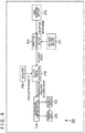
- FIG. 6 is a block diagram illustrating a main configuration example of the high sensitivity reception apparatus 102.
- the high sensitivity reception apparatus 102 includes a criterion setting section 311, a GNSS reception section 312, a correction determination section 313, an oscillator 314, a clock counter 315, a clock section 316, a reception schedule control section 317, a reception control section 318, an oscillation section 319, and a reception section 320.
- the criterion setting section 311 performs a process related to setting of a criterion related to determination regarding reception time-of-day control.
- the criterion setting section 311 can be realized by arbitrary components.
- the criterion setting section 311 may include a circuit, an LSI (Large Scale Integration), a system LSI, a processor, a module, a unit, a set, a device, an apparatus, a system, or the like. Alternatively, a plurality thereof may be used in combination.
- the criterion setting section 311 may include a CPU and a memory, and the CPU performs the above process by executing a program using the memory.
- the GNSS reception section 312 performs a process related to reception of a GNSS signal.
- the GNSS reception section 312 can be realized by arbitrary components.
- the GNSS reception section 312 may include a circuit, an LSI, a system LSI, a processor, a module, a unit, a set, a device, an apparatus, a system, or the like.
- a plurality thereof may be used in combination.
- a plurality of components of the same kind such as a plurality of circuits or a plurality of processors may be used in combination, or a plurality of components of different kinds such as a circuit and an LSI may be used in combination.
- the GNSS reception section 312 may include an antenna, a reception circuit, a signal processing circuit, and so on.
- the correction determination section 313 performs a process related to determination regarding reception time-of-day control.
- the correction determination section 313 can be realized by arbitrary components.
- the correction determination section 313 may include a circuit, an LSI, a system LSI, a processor, a module, a unit, a set, a device, an apparatus, a system, or the like. Alternatively, a plurality thereof may be used in combination. At this time, for example, a plurality of components of the same kind such as a plurality of circuits or a plurality of processors may be used in combination, or a plurality of components of different kinds such as a circuit and an LSI may be used in combination.
- the correction determination section 313 may include a CPU and a memory, and the CPU performs the above process by executing a program using the memory.
- the oscillator 314 oscillates at a given oscillation frequency and generates a signal at that oscillation frequency.
- the oscillator 314 can be realized by arbitrary components.
- the oscillator 314 may include a circuit, an LSI, a system LSI, a processor, a module, a unit, a set, a device, an apparatus, a system, or the like.
- a plurality thereof may be used in combination.
- a plurality of components of the same kind such as a plurality of circuits or a plurality of processors may be used in combination, or a plurality of components of different kinds such as a circuit and an LSI may be used in combination.
- the oscillator 314 may include an oscillation circuit and so on. It should be noted that this oscillator 314 oscillates in an arbitrary manner.
- the clock counter 315 performs a process related to generation of time of day based on a signal generated by the oscillator 314.
- the clock counter 315 can be realized by arbitrary components.
- the clock counter 315 may include a circuit, an LSI, a system LSI, a processor, a module, a unit, a set, a device, an apparatus, a system, or the like. Alternatively, a plurality thereof may be used in combination. At this time, for example, a plurality of components of the same kind such as a plurality of circuits or a plurality of processors may be used in combination, or a plurality of components of different kinds such as a circuit and an LSI may be used in combination.
- the clock counter 315 may include a CPU and a memory, and the CPU performs the above process by executing a program using the memory.
- the clock section 316 performs a process related to generation of time-of-day information to be used for reception timing control.
- the clock section 316 can be realized by arbitrary components.
- the clock section 316 may include a circuit, an LSI, a system LSI, a processor, a module, a unit, a set, a device, an apparatus, a system, or the like.
- a plurality thereof may be used in combination.
- a plurality of components of the same kind such as a plurality of circuits or a plurality of processors may be used in combination, or a plurality of components of different kinds such as a circuit and an LSI may be used in combination.
- the clock section 316 may include a CPU and a memory, and the CPU performs the above process by executing a program using the memory.
- the reception schedule control section 317 performs a process related to reception schedule control.
- the reception schedule control section 317 can be realized by arbitrary components.
- the reception schedule control section 317 may include a circuit, an LSI, a system LSI, a processor, a module, a unit, a set, a device, an apparatus, a system, or the like.
- a plurality thereof may be used in combination.
- a plurality of components of the same kind such as a plurality of circuits or a plurality of processors may be used in combination, or a plurality of components of different kinds such as a circuit and an LSI may be used in combination.
- the reception schedule control section 317 may include a CPU and a memory, and the CPU performs the above process by executing a program using the memory.
- the reception control section 318 performs a process related to reception control.
- the reception control section 318 can be realized by arbitrary components.
- the reception control section 318 may include a circuit, an LSI, a system LSI, a processor, a module, a unit, a set, a device, an apparatus, a system, or the like.
- a plurality thereof may be used in combination.
- a plurality of components of the same kind such as a plurality of circuits or a plurality of processors may be used in combination, or a plurality of components of different kinds such as a circuit and an LSI may be used in combination.
- the reception control section 318 may include a CPU and a memory, and the CPU performs the above process by executing a program using the memory.
- the oscillation section 319 performs a process related to setting of a reception frequency.
- the oscillation section 319 can be realized by arbitrary components.
- the oscillation section 319 may include a circuit, an LSI, a system LSI, a processor, a module, a unit, a set, a device, an apparatus, a system, or the like.
- a plurality thereof may be used in combination.
- a plurality of components of the same kind such as a plurality of circuits or a plurality of processors may be used in combination, or a plurality of components of different kinds such as a circuit and an LSI may be used in combination.
- the oscillation section 219 may include an oscillation circuit and so on. It should be noted that this oscillation section 319 oscillates in an arbitrary manner.
- the reception section 320 performs a process related to reception.
- the reception section 320 can be realized by arbitrary components.
- the reception section 320 may include a circuit, an LSI, a system LSI, a processor, a module, a unit, a set, a device, an apparatus, a system, or the like.
- a plurality thereof may be used in combination.
- a plurality of components of the same kind such as a plurality of circuits or a plurality of processors may be used in combination, or a plurality of components of different kinds such as a circuit and an LSI may be used in combination.
- the reception section 320 may include an antenna, a reception circuit, a signal processing circuit, and so on.
- the clock section 316 sets time-of-day information, information for controlling reception of a signal, on the basis of a GNSS signal received by the GNSS reception section 312 or an oscillation frequency of the oscillator 314 (signal frequency generated by the oscillator 314).
- the reception control section 318 (and the reception schedule control section 317) control the reception of a signal on the basis of the time-of-day information.
- the reception section 320 sends a received signal under such control, i.e., at the reception time of day specified by the time-of-day information.
- This reception time of day corresponds to the transmission time of day of the transmission apparatus 101. That is, this makes it possible to suppress reduction in control accuracy even in the case where the GNSS signal reception quality is insufficient, thus suppressing reduction in communication quality.
- the clock section 316 can select the GNSS signal or the oscillation frequency in accordance with the reception status of the GNSS signal and set the information by using the selected option. Therefore, it is possible to suppress reduction in control accuracy even in the case where the GNSS signal reception quality is insufficient, thus suppressing reduction in communication quality.
- the clock section 316 can set time-of-day information by using the GNSS signal, and in the case where the received GNSS signal has a lower quality than the criterion, the setting section can set time-of-day information by using the oscillation frequency.
- the clock section 316 can set time of day acquired from the GNSS signal as time-of-day information, and in the case where the received GNSS signal has a lower quality than the criterion, the setting section can set time of day acquired by counting by the clock counter 315 at timings synchronous with the oscillation frequency as time-of-day information. Therefore, it is possible to suppress reduction in control accuracy even in the case where the GNSS signal reception quality is insufficient, thus suppressing reduction in communication quality.
- the reception control section 318 (and the reception schedule control section 317) can control the reception section 320 to receive a signal from a predetermined transmitting side at a known reception timing on the basis of time-of-day information set by the clock section 316. Therefore, it is possible to receive a signal at a more accurate reception timing, thus suppressing reduction in communication quality.
- the oscillator 314 oscillates at an oscillation frequency and generates a signal at that frequency.
- the oscillator 314 supplies the signal to the clock counter 315.
- the clock counter 315 counts at timings synchronous with the frequency of the signal supplied from the oscillator 314 (i.e., oscillation frequency) and sets time of day based on the oscillation frequency (also referred to as an oscillator-generated time of day).
- the clock counter 315 supplies the oscillator-generated time of day to the clock section 316.
- the clock section 316 can set time-of-day information by using the oscillator-generated time of day as described above.
- the clock counter 315 configured in this manner can, in the case where the received GNSS signal has a higher quality than a given criterion, correct the time of day acquired by counting at timings synchronous with the oscillation frequency given by the oscillator 314 by using the time of day acquired from the GNSS signal by the correction determination section 313. This makes the time of day based on the oscillation frequency more accurate, allowing to set more accurate time-of-day information even in the case where the GNSS signal reception quality is insufficient and suppressing reduction in communication quality.
- the GNSS reception section 312 receives, for example, a GNSS signal.
- the clock section 316 can set time-of-day information on the basis of the GNSS signal received by the GNSS reception section 312 or the oscillation frequency.
- the correction determination section 313 determines, for example, whether the GNSS signal received by the GNSS reception section 312 has a sufficiently high quality on the basis of a criterion set by the criterion setting section 311. Then, in the case where the correction determination section 313 determines that the GNSS signal has a sufficiently high quality, the correction determination section 313 sets time of day (time of day including correction) on the basis of the GNSS signal received by the GNSS reception section 312.
- the correction determination section 313 supplies this time of day based on the GNSS signal to the clock counter 315 and the clock section 316.
- the clock section 316 can generate time-of-day information from this time of day based on the GNSS signal as described above.
- the clock counter 315 can correct time of day based on the oscillation frequency by using this time of day based on the GNSS signal as described above.
- the criterion setting section 311 sets, in step S201, a correction eligibility determination criterion that will be used as a threshold for determination made by the correction determination section 313.
- This criterion is set in an arbitrary manner. For example, a predetermined value may be set. Alternatively, a criterion may be specified by a user or other individual or may be set to suit an external or internal environment.
- the criterion setting section 311 supplies the set correction eligibility determination criterion to the correction determination section 313.
- the GNSS reception section 312 receives a GNSS signal.
- This GNSS signal includes a variety of pieces of information such as time-of-day information and position information of the navigation satellite that sent the GNSS signal.
- the GNSS reception section 312 supplies, to the correction determination section 313, these pieces of information included in the received GNSS signal as received information.
- the correction determination section 313 determines the quality of the received information.
- the correction determination section 313 determines (evaluates) the quality of the received information on the basis of information such as the number of satellites from which the GNSS signals were successfully received, CNR (Carrier to Noise ratio) of each satellite, doppler frequency, altitude, and leap seconds.
- CNR Carrier to Noise ratio
- step S204 the correction determination section 313 determines whether the received information has a high quality by using the correction eligibility determination criterion set by the criterion setting section 311 as a threshold. In the case where it is determined that the received information exceeds the correction eligibility determination criterion and that, therefore, the received information has a sufficiently high quality, the process proceeds to step S205.
- step S205 the correction determination section 313 sets time of day based on the GNSS signal (time of day including correction) by using the received information and supplies the time of day including correction to the clock counter 315 and the clock section 316.
- This time of day including correction is time of day based on time-of-day information of the navigation satellite as described above and is more accurate than the time of day based on the oscillation frequency.
- the time of day including correction includes correction made to the time of day based on the oscillation frequency.
- step S206 the clock section 316 sets the time of day including correction as time-of-day information.
- the clock section 316 supplies the set time-of-day information to the reception schedule control section 317.
- time of day including correction acquired on the basis of the GNSS signal is sufficiently accurate. This makes it possible for the clock section 316 to set more accurate time-of-day information by using the accurate time of day including correction. Therefore, the high sensitivity reception apparatus 102 can suppress reduction in communication quality by receiving a signal on the basis of the more accurate time-of-day information.
- step S207 the clock counter 315 corrects its own count value, i.e., the oscillator-generated time of day using the time of day including correction generated by the process in step S205. Therefore, the clock counter 315 can render the oscillator-generated time of day (count value) more accurate by correcting the oscillator-generated time of day using the accurate time of day including correction. This makes it possible for the high sensitivity reception apparatus 102 to set more accurate time-of-day information even in the case where the GNSS signal reception quality is insufficient, thus suppressing reduction in communication quality.
- step S207 ends, the process proceeds to step S210. Also, in the case where it is determined in step S204 that the received information quality does not exceed the correction eligibility determination criterion and that, therefore, the received information is not of a sufficiently high quality (is of a low quality), the process proceeds to step S208.
- step S208 the clock counter 315 generates oscillator-generated time of day from the oscillation frequency of the oscillator 314.
- step S209 the clock section 316 sets the oscillator-generated time of day generated by the process in step S208 as time-of-day information.
- time-of-day information is set by using time of day based on the oscillation frequency generated inside the high sensitivity reception apparatus 102 without relying on the GNSS signal. Therefore, even in the case where the GNSS signal reception quality is insufficient, the high sensitivity reception apparatus 102 can suppress reduction in time-of-day information accuracy attributable to the use of an interpolation formula or other cause, thus suppressing reduction in communication quality.
- step S210 the reception schedule control section 317 sets a reception timing for receiving a signal on the basis of the time-of-day information supplied from the clock section 316 and a reception schedule corresponding to the known transmission schedule (predetermined reception schedule).
- This reception timing corresponds to the transmission timing of the transmission apparatus 101, i.e., a timing suitable for receiving a signal sent at the transmission timing.
- the reception schedule control section 317 can set the reception timing to accurate time of day by setting the reception timing using the time-of-day information set as described above. This makes it possible to suppress reduction in communication quality.
- the reception schedule control section 317 supplies the set reception timing to the reception control section 318.
- the reception control section 318 controls the oscillation section 319 and the reception section 320 to receive a transmission signal sent from the transmission apparatus 101 at the reception timing set in step S210.
- the oscillation section 319 oscillates at a given oscillation frequency (e.g., 920-MHz band) under control of the reception control section 318 and supplies the signal at that oscillation frequency to the reception section 320.
- the reception section 320 receives, under control of the reception control section 318, a signal at the reception timing described above at the oscillation frequency of the oscillation section 319 (i.e., receives a signal sent at the same frequency as the oscillation frequency of the oscillation section 319).
- the reception section 320 can receive a signal at a more accurate reception timing by receiving a signal in this manner under control of the reception control section 318 even if the GNSS signal reception quality is insufficient. This makes it possible to suppress reduction in communication quality.
- the reception section 320 can suppress reduction in accuracy for identification of each of the multiplexed signals by receiving the signals under control of the reception control section 318 even if the GNSS signal reception quality is insufficient. In other words, it is possible to more accurately receive a signal that includes a larger number of multiplexed signals. This makes it possible to suppress reduction in communication quality.
- the reception section 320 extracts identification information, position information, and other information of the transmission apparatus 101 from the received signal and supplies these pieces of information to the server 104.
- step S211 When the process in step S211 ends, the reception process is terminated.
- the high sensitivity reception apparatus 102 can suppress reduction in communication quality.
- the transmission apparatus 101 can control not only transmission time of day as described above but also a transmission frequency in the transmission of a transmission signal.
- frequency division multiplexing it is possible to multiplex a larger number of signals by improving the accuracy for controlling the frequency of a transmission signal.
- frequency control requires an accuracy of approximately 10 Hz.
- common oscillators incorporated in the transmission apparatus 101 and the high sensitivity reception apparatus 102 it has been difficult for common oscillators incorporated in the transmission apparatus 101 and the high sensitivity reception apparatus 102 to realize such an accuracy. For this reason, use of a GNSS signal was conceived to control frequency as in the case of time-of-day control described above.
- a vector of the speed of a navigation satellite (satellite speed) is denoted as Vs
- the doppler frequency is denoted as fd
- the speed of a receiver (receiver speed) is denoted as Vu
- the vector from the navigation satellite to the receiver is denoted as D
- Vd Vs ⁇ Vu ⁇ e
- Such navigation satellites have highly accurate cesium oscillators, allowing them to acquire more accurate time-of-day information than oscillators normally incorporated in receivers and other apparatuses.
- a frequency acquired by a receiver on the basis of GNSS signals as described above is more accurate than the oscillation frequency of the oscillator incorporated in the receiver (the frequency remains invariable).
- the transmission apparatus 101 and the high sensitivity reception apparatus 102 of the position notification system 100 can improve the accuracy for frequency control during signal transmission and reception by using the frequency acquired from GNSS signals as described above. In other words, it is possible to realize communication of higher quality.
- GNSS signals are not always received properly.
- the offset of the receiver's oscillator frequency deteriorates in accuracy.
- a decline in frequency control accuracy may cause mixing of signals during frequency division multiplexing and reduced reception sensitivity due to increased error in signal transmission and reception times of day, possibly resulting in reduced communication quality.
- information for controlling transmission of a transmission signal is set on the basis of the GNSS signal or the oscillation frequency of the oscillator, the transmission of the transmission signal is controlled on the basis of the set information, and the transmission signal is sent in accordance with the transmission control. This suppresses reduction in frequency control accuracy, thus suppressing reduction in communication quality.
- FIG. 9 is a block diagram illustrating a main configuration example of the transmission apparatus 101 in the case where frequency control is performed.
- the transmission apparatus 101 includes a correction determination section 413 in place of the correction determination section 213 illustrated in FIG. 4 , and an oscillation frequency calculation section 416 in place of the clock counter 215, the clock section 216, and the transmission schedule control section 217.
- the correction determination section 413 performs a process related to determination regarding transmission frequency control.
- the correction determination section 413 can be realized by arbitrary components.
- the correction determination section 413 may include a circuit, an LSI, a system LSI, a processor, a module, a unit, a set, a device, an apparatus, a system, or the like. Alternatively, a plurality thereof may be used in combination. At this time, for example, a plurality of components of the same kind such as a plurality of circuits or a plurality of processors may be used in combination, or a plurality of components of different kinds such as a circuit and an LSI may be used in combination.
- the correction determination section 413 may include a CPU and a memory, and the CPU performs the above process by executing a program using the memory.
- the oscillation frequency calculation section 416 performs a process related to setting of a transmission frequency after correction (transmission frequency including error).
- the oscillation frequency calculation section 416 can be realized by arbitrary components.
- the oscillation frequency calculation section 416 may include a circuit, an LSI, a system LSI, a processor, a module, a unit, a set, a device, an apparatus, a system, or the like. Alternatively, a plurality thereof may be used in combination. At this time, for example, a plurality of components of the same kind such as a plurality of circuits or a plurality of processors may be used in combination, or a plurality of components of different kinds such as a circuit and an LSI may be used in combination.
- the oscillation frequency calculation section 416 may include a CPU and a memory, and the CPU performs the above process by executing a program using the memory.
- the oscillation frequency calculation section 416 sets a transmission control frequency (also referred to as a transmission frequency including error), information for controlling transmission of a transmission signal, on the basis of a GNSS signal received by the GNSS reception section 212 or an oscillation frequency of the oscillator 214 (signal frequency generated by the oscillator 214).
- the transmission control section 218 controls the transmission of a transmission signal on the basis of the transmission control frequency.
- the oscillation section 219 oscillates under such control, i.e., at the transmission frequency based on the specified transmission control frequency, and the transmission section 220 sends a transmission signal at that transmission frequency. This suppresses reduction in control accuracy even in the case where the GNSS signal reception quality is insufficient. In other words, a transmission signal can be sent more accurately at a desired frequency (transmission frequency).
- this transmission frequency is a frequency known to the receiving side. In other words, this can suppress a shift of the transmission frequency from the frequency known to the receiving side. In other words, the transmission apparatus 101 allows the high sensitivity reception apparatus 102 to adjust the reception frequency to more accurately match the frequency of the transmission signal.
- the transmission apparatus 101 can, by proceeding as described above, suppress reduction in frequency control accuracy even in the case where the GNSS signal reception quality is insufficient, thus allowing for multiplexing of a larger number of signals while preventing mixing of the signals.
- the transmission apparatus 101 can suppress reduction in reception sensitivity of the high sensitivity reception apparatus 102 even in the case where the GNSS signal reception quality is insufficient, thus suppressing reduction in communication quality.
- the oscillation frequency calculation section 416 can select the GNSS signal or the oscillation frequency in accordance with the reception status of the GNSS signal and set the transmission control frequency by using the selected option. This makes it possible to suppress reduction in control accuracy even in the case where the GNSS signal reception quality is insufficient, thus suppressing reduction in communication quality.
- the oscillation frequency calculation section 416 can set a transmission frequency including error by using the GNSS signal, and in the case where the received GNSS signal has a lower quality than the criterion, the oscillation frequency calculation section 416 can set a transmission frequency including error by using the oscillation frequency. More specifically, in the case where the received GNSS signal has a higher quality than a given criterion, the oscillation frequency calculation section 416 can correct the frequency of the signal supplied from the oscillator 214 (oscillation frequency) by using a frequency error acquired from the GNSS signal received this time and set the corrected frequency as a transmission control frequency.
- the oscillation frequency calculation section 416 can correct the frequency of the signal supplied from the oscillator 214 (oscillation frequency) by using the correction value used during the previous correction and set the corrected frequency as a transmission control frequency.
- the previous correction value is a value acquired in the case where the GNSS signal has a high quality. Therefore, it is possible to acquire a more accurate transmission control frequency by using this value than in the case where the correction value acquired from the current low-quality GNSS signal is used. This makes it possible to suppress reduction in control accuracy even in the case where the GNSS signal reception quality is insufficient, thus suppressing reduction in communication quality.
- the transmission control section 218 controls the oscillation section 219 to oscillate at a transmission frequency based on the transmission control frequency set by the oscillation frequency calculation section 416. Then, the transmission control section 218 can control the transmission section 220 to send a transmission signal at the transmission frequency. This makes it possible to send a transmission signal at a more accurate transmission frequency, thus suppressing reduction in communication quality.
- the transmission control section 218 can set each of the signals to be multiplexed to an accurate frequency by causing the transmission signals to be sent at a transmission frequency based on the transmission control frequency set by the oscillation frequency calculation section 416. Also, in the case where time division multiplexing using chirp modulation is applied to transmission signals, the transmission control section 218 can narrow a bandwidth of each signal by causing the transmission signals to be sent at a transmission frequency based on the transmission control frequency set by the oscillation frequency calculation section 416. This makes it possible to multiplex a larger number of signals while preventing mixing of the signals, thus suppressing reduction in communication quality.
- the GNSS reception section 212 receives, for example, a GNSS signal.
- the oscillation frequency calculation section 416 can set a transmission control frequency on the basis of the GNSS signal received by the GNSS reception section 212 or the oscillation frequency.
- the correction determination section 213 determines, for example, whether the GNSS signal received by the GNSS reception section 212 has a sufficiently high quality on the basis of a criterion set by the criterion setting section 211. Then, in the case where the correction determination section 213 determines that the GNSS signal has a sufficiently high quality, the correction determination section 213 sets a frequency (frequency error) on the basis of the GNSS signal received by the GNSS reception section 212.
- the correction determination section 213 supplies this frequency error based on the GNSS signal to the oscillation frequency calculation section 416.
- the oscillation frequency calculation section 416 can generate a transmission control frequency from this frequency error based on the GNSS signal as described above.
- step S301 to step S304 are performed as are the processes from step S101 to step S104 in FIG. 5 . It should be noted, however, that the processes in steps S303 and S304 are performed by the correction determination section 413. In the case where it is determined in step S304 that the received information quality exceeds the correction eligibility determination criterion and that, therefore, the received information has a sufficiently high quality, the process proceeds to step S305.
- step S305 the correction determination section 413 sets a frequency (frequency error) based on the GNSS signal by using the received information and supplies the frequency error to the oscillation frequency calculation section 416.
- This frequency error is a correction value based on information such as navigation satellite speed as described above.
- step S306 the oscillation frequency calculation section 416 corrects the oscillation frequency acquired by the oscillator 214 with the frequency error set in step S305 and sets the corrected frequency as a transmission frequency including error.
- the oscillation frequency calculation section 416 supplies the transmission frequency including error to the transmission control section 218.
- a frequency error acquired on the basis of the GNSS signal is also sufficiently accurate. This makes it possible for the oscillation frequency calculation section 416 to set a more accurate transmission frequency including error by correcting the oscillation frequency by using the accurate frequency error. Therefore, the transmission apparatus 101 can suppress reduction in communication quality by sending a transmission signal at a transmission frequency based on the more accurate transmission frequency including error.
- step S306 ends, the process proceeds to step S308. Also, in the case where it is determined in step S304 that the received information quality does not exceed the correction eligibility determination criterion and that, therefore, the received information is not of a sufficiently high quality (is of a low quality), the process proceeds to step S307.
- step S307 the oscillation frequency calculation section 416 corrects the oscillation frequency of the oscillator 214 with the same frequency error as the previous one.
- the oscillation frequency calculation section 416 supplies the transmission frequency including error to the transmission control section 218.
- the oscillation frequency is corrected by using the frequency error based on the high-quality GNSS signal without relying on the low-quality GNSS signal. Therefore, even in the case where the GNSS signal reception quality is insufficient, the transmission apparatus 101 can suppress reduction in frequency accuracy attributable to the use of an interpolation formula or other cause, thus suppressing reduction in communication quality.
- step S308 the transmission control section 218 controls the oscillation section 219 and the transmission section 220 to send a transmission signal at a transmission frequency based on the transmission frequency including error acquired by the processes in step S306 or S307.
- the oscillation section 219 oscillates at the transmission frequency under control of the transmission control section 218 and supplies the signal at that transmission frequency to the transmission section 220.
- the transmission section 220 generates a transmission signal and sends, under control of the transmission control section 218, the transmission signal at the frequency of the signal supplied from the oscillation section 219 (transmission frequency). It should be noted that this transmission frequency is known to the receiving side. This makes it possible for the transmission section 220 to send a transmission signal at an accurate transmission frequency even if the GNSS signal reception quality is insufficient, thus suppressing reduction in communication quality.
- a transmission signal is generated in an arbitrary manner.
- a transmission signal has arbitrary contents. For example, time-of-day information, position information, and other information of the transmission apparatus 101 may be included.
- transmission signals may be frequency division-multiplexed before transmission.
- the transmission section 220 can send transmission signals at a more accurate transmission frequency by sending the transmission signals under control of the transmission control section 218 even if the GNSS signal reception quality is insufficient, thus allowing for multiplexing of a larger number of signals while preventing mixing of the signals. This makes it possible to suppress reduction in communication quality.
- transmission signals may be time division-multiplexed by using chirp modulation.
- the transmission section 220 can also narrow the bandwidth of each signal by sending the transmission signals under control of the transmission control section 218. This makes it possible to multiplex a larger number of signals while preventing mixing of the signals. Therefore, it is possible to suppress reduction in communication quality.
- step S308 ends, the transmission process is terminated.
- the transmission apparatus 101 can suppress reduction in communication quality.
- More accurate frequency control can be performed in the high sensitivity reception apparatus 102 by using a GNSS signal as in the transmission apparatus 101.
- a GNSS signal as in the transmission apparatus 101.
- information for controlling reception of a signal sent from the transmitting side is set on the basis of the GNSS signal or the oscillation frequency of the oscillator, the reception of the signal is controlled on the basis of the set information, and the signal is received in accordance with the reception control. This suppresses reduction in frequency control accuracy, thus suppressing reduction in communication quality.
- FIG. 11 is a block diagram illustrating a main configuration example of the high sensitivity reception apparatus 102 in the case where frequency control is performed.
- the high sensitivity reception apparatus 102 includes a correction determination section 513 in place of the correction determination section 313 in FIG. 6 and an oscillation frequency calculation section 516 in place of the clock counter 315, the clock section 316, and the reception schedule control section 317.
- the correction determination section 513 performs a process related to determination regarding transmission frequency control.
- the correction determination section 513 can be realized by arbitrary components.
- the correction determination section 513 may include a circuit, an LSI, a system LSI, a processor, a module, a unit, a set, a device, an apparatus, a system, or the like. Alternatively, a plurality thereof may be used in combination. At this time, for example, a plurality of components of the same kind such as a plurality of circuits or a plurality of processors may be used in combination, or a plurality of components of different kinds such as a circuit and an LSI may be used in combination.
- the correction determination section 513 may include a CPU and a memory, and the CPU performs the above process by executing a program using the memory.
- the oscillation frequency calculation section 516 performs a process related to setting of a reception frequency after correction (reception frequency including error).
- the oscillation frequency calculation section 516 can be realized by arbitrary components.
- the oscillation frequency calculation section 516 may include a circuit, an LSI, a system LSI, a processor, a module, a unit, a set, a device, an apparatus, a system, or the like. Alternatively, a plurality thereof may be used in combination. At this time, for example, a plurality of components of the same kind such as a plurality of circuits or a plurality of processors may be used in combination, or a plurality of components of different kinds such as a circuit and an LSI may be used in combination.
- the oscillation frequency calculation section 516 may include a CPU and a memory, and the CPU performs the above process by executing a program using the memory.
- the oscillation frequency calculation section 516 sets a reception control frequency (also referred to as a reception frequency including error), information for controlling reception of a signal, on the basis of the GNSS signal received by the GNSS reception section 312 or the oscillation frequency of the oscillator 314 (signal frequency generated by the oscillator 314).
- the reception control section 318 controls the reception of a signal (sent from the transmission apparatus 101) on the basis of the reception control frequency.
- the oscillation section 319 oscillates under such control, i.e., at the reception frequency based on the specified reception control frequency, and the reception section 320 receives the signal at that reception frequency. This makes it possible to suppress reduction in frequency control accuracy even in the case where the GNSS signal reception quality is insufficient. That is, a signal can be received at a more accurate desired frequency (reception frequency).
- this reception frequency is a frequency corresponding to the transmission frequency of a transmission signal sent from the transmission apparatus 101 (frequency known to the receiving side). That is, this allows the high sensitivity reception apparatus 102 to suppress a shift of the reception frequency from the frequency suitable for reception of the transmission signal sent from the transmission apparatus 101.
- the high sensitivity reception apparatus 102 can, by proceeding as described above, suppress reduction in accuracy for identification of each of the multiplexed signals even if the GNSS signal reception quality is insufficient. In other words, it is possible to more accurately receive a signal that includes a larger number of multiplexed signals. This makes it possible to suppress reduction in communication quality.
- the high sensitivity reception apparatus 102 can suppress reduction in reception sensitivity even in the case where the GNSS signal reception quality is insufficient, thus suppressing reduction in communication quality.
- the oscillation frequency calculation section 516 can select the GNSS signal or the oscillation frequency in accordance with the reception status of the GNSS signal and set the reception control frequency by using the selected option. This makes it possible to suppress reduction in control accuracy even in the case where the GNSS signal reception quality is insufficient, thus suppressing reduction in communication quality.
- the oscillation frequency calculation section 516 can set a reception frequency including error by using the GNSS signal, and in the case where the received GNSS signal has a lower quality than the criterion, the oscillation frequency calculation section 516 can set a reception frequency including error by using the oscillation frequency. More specifically, in the case where the received GNSS signal has a higher quality than a given criterion, the oscillation frequency calculation section 516 can correct the frequency of the signal supplied from the oscillator 314 (oscillation frequency) by using a frequency error acquired from the GNSS signal received this time and set the corrected frequency as a reception control frequency.
- the oscillation frequency calculation section 516 can correct the frequency of the signal supplied from the oscillator 314 (oscillation frequency) by using the correction value used during the previous correction and set the corrected frequency as a reception control frequency.
- the previous correction value is a value acquired in the case where the GNSS signal has a high quality. Therefore, it is possible to acquire a more accurate reception control frequency by using this value than in the case where the correction value acquired from the current low-quality GNSS signal is used. This makes it possible to suppress reduction in control accuracy even in the case where the GNSS signal reception quality is insufficient, thus suppressing reduction in communication quality.
- the reception control section 318 can control the oscillation section 319 to oscillate at a reception frequency based on the reception control frequency set by the oscillation frequency calculation section 516. Then, the reception control section 318 can control the reception section 320 to receive a signal at the reception frequency. This makes it possible to receive a signal at a more accurate transmission frequency, thus suppressing reduction in communication quality.
- the reception control section 318 can suppress reduction in accuracy for identification of each of the multiplexed signals by causing the signals to be received at a reception frequency based on the reception control frequency set by the oscillation frequency calculation section 516. In other words, it is possible to suppress reduction in communication quality.
- the GNSS reception section 312 receives, for example, a GNSS signal.
- the oscillation frequency calculation section 516 can set a reception control frequency on the basis of the GNSS signal received by the GNSS reception section 312 or the oscillation frequency.
- the correction determination section 513 determines, for example, whether the GNSS signal received by the GNSS reception section 312 has a sufficiently high quality on the basis of a criterion set by the criterion setting section 311. Then, in the case where the correction determination section 513 determines that the GNSS signal has a sufficiently high quality, the correction determination section 513 sets a frequency (frequency error) on the basis of the GNSS signal received by the GNSS reception section 312. The correction determination section 513 supplies this frequency error based on the GNSS signal to the oscillation frequency calculation section 516.
- the oscillation frequency calculation section 516 can generate a reception control frequency from this frequency error based on the GNSS signal as described above.
- step S401 to step S404 are performed as are the processes from step S201 to step S204 in FIG. 7 . It should be noted, however, that the processes in steps S403 and S404 are performed by the correction determination section 513. In the case where it is determined in step S404 that the received information quality exceeds the correction eligibility determination criterion and that, therefore, the received information has a sufficiently high quality, the process proceeds to step S405.
- step S405 the correction determination section 513 sets a frequency (frequency error) based on the GNSS signal by using the received information and supplies the frequency error to the oscillation frequency calculation section 516.
- This frequency error is a correction value based on information such as navigation satellite speed as described above.
- step S406 the oscillation frequency calculation section 516 corrects the oscillation frequency acquired by the oscillator 314 with the frequency error set in step S405 and sets the corrected frequency as a reception frequency including error.
- the oscillation frequency calculation section 516 supplies the reception frequency including error to the reception control section 318.
- a frequency error acquired on the basis of the GNSS signal is also sufficiently accurate. This makes it possible for the oscillation frequency calculation section 516 to set a more accurate reception frequency including error by correcting the oscillation frequency by using the accurate frequency error. Therefore, the high sensitivity reception apparatus 102 can suppress reduction in communication quality by receiving a signal at a reception frequency based on the more accurate reception frequency including error.
- step S406 ends, the process proceeds to step S408. Also, in the case where it is determined in step S404 that the received information quality does not exceed the correction eligibility determination criterion and that, therefore, the received information is not of a sufficiently high quality (is of a low quality), the process proceeds to step S407.
- step S407 the oscillation frequency calculation section 516 corrects the oscillation frequency of the oscillator 314 with the same frequency error as the previous one. That is, in the case where the GNSS signal reception quality is low, the oscillation frequency is corrected by using the frequency error based on the high-quality GNSS signal without relying on the low-quality GNSS signal. Therefore, even in the case where the GNSS signal reception quality is insufficient, the high sensitivity reception apparatus 102 can suppress reduction in time-of-day information accuracy attributable to the use of an interpolation formula or other cause, thus suppressing reduction in communication quality.
- step S408 the reception control section 318 controls the oscillation section 319 and the reception section 320 to receive a signal at a reception frequency based on the reception frequency including error acquired by acquired by the processes in step S406 or S407.
- the oscillation section 319 oscillates at the reception frequency under control of the reception control section 318 and supplies a signal at the reception frequency to the reception section 320.
- the reception section 320 receives, under control of the reception control section 318, a signal at the frequency (reception frequency) of the signal supplied from the oscillation section 319 (that is, receives a signal sent at the same frequency as the oscillation frequency of the oscillation section 319).
- the reception section 320 can receive a signal at a more accurate reception frequency by receiving the signal under control of the reception control section 318 as described above even if the GNSS signal reception quality is insufficient. Therefore, it is possible to suppress reduction in control accuracy.
- the reception section 320 can suppress reduction in accuracy for identification of each of the multiplexed signals by receiving the signals under control of the reception control section 318 even if the GNSS signal reception quality is insufficient. That is, it is possible to more accurately receive a signal that includes a larger number of multiplexed signals. This makes it possible to suppress reduction in communication quality.
- the reception section 320 extracts identification information, position information, and other information of the transmission apparatus 101 from the received signal and supplies these pieces of information to the server 104.
- step S408 When the process in step S408 ends, the reception process is terminated.
- the high sensitivity reception apparatus 102 can suppress reduction in communication quality.
- the present technology may be applied only to the transmission apparatus 101, only to the high sensitivity reception apparatus 102, or to both the transmission apparatus 101 and the high sensitivity reception apparatus 102. Also, the present technology may be applied to a transmission/reception apparatus having transmission and reception functions. In that case, the present technology may be applied only to the transmission function, only to the reception function, or to both the transmission and reception functions.
- the transmission apparatus 101 may perform both time-of-day control and frequency control in signal transmission.
- the present technology may be applied only to time-of-day control, only to frequency control, or to both time-of-day control and frequency control.
- the high sensitivity reception apparatus 102 may perform both time-of-day control and frequency control in signal reception. In that case, the present technology may be applied only to time-of-day control, only to frequency control, or to both time-of-day control and frequency control.
- the present technology is applicable to an arbitrary communication system.
- the transmission apparatus 101 may be installed not only on a person but also on a moving body or other object.
- the present technology is applicable to a theft prevention system 800 for preventing theft of an automobile, motorcycle, or other vehicle illustrated in FIG. 13 .
- the transmission apparatus 101 is installed on a subject whose position is monitored by a user such as an automobile 801 or a motorcycle 802 owned by the user.
- the transmission apparatus 101 notifies its own position information (i.e., position information of the automobile 801 or the motorcycle 802) to the high sensitivity reception apparatus 102 as appropriate as in the case of the position notification system 100.
- the user can access the server 104 from the terminal apparatus 105 and find out the position of the automobile 801 or the motorcycle 802 as in the case of the position notification system 100. Therefore, the user can find out the position of the automobile 801 or the motorcycle 802 even in the event of a theft, thus allowing him or her to readily recover the automobile 801 or the motorcycle 802.
- the theft prevention system 800 it is also possible to suppress reduction in communication quality by applying the present technology described above in each of the embodiments to the transmission apparatus 101 and the high sensitivity reception apparatus 102, thus allowing for more accurate notification of its own position information (i.e., position information of the automobile 801 or the motorcycle 802) to the high sensitivity reception apparatus 102.
- its own position information i.e., position information of the automobile 801 or the motorcycle 802
- the user can find out the position of the automobile 801 or the motorcycle 802 more readily and more accurately even in the event of a theft.
- the transmission apparatus 101 may send transmission information including control information such as an image, sound, measurement data, identification information of equipment or the like, parameter setting information, or instruction.
- this transmission information may include, for example, a plurality of kinds of information such as image and sound or identification information, setting information, and control information.
- the transmission apparatus 101 may be able to send, for example, transmission information including information supplied from other apparatus.
- the transmission apparatus 101 may generate transmission information including information output from various sensors (sensor output) for detecting, measuring, or performing other task on an arbitrary variable such as image, light, brightness, saturation, electricity, sound, vibration, acceleration, speed, angular speed, force, temperature (not temperature distribution), humidity, distance, area, volume, shape, flowrate, time of day, time, magnetism, chemical substance, or odor, or a variation of such a variable.
- the present technology is applicable to a system used for an arbitrary application such as stereoscopic shape measurement, spatial measurement, object observation, movement deformation observation, biological observation, authentication process, monitoring, autofocus, imaging control, illumination control, tracking process, input/output control, electronic equipment control, or actuator control.
- the present technology is applicable to a system in an arbitrary field such as traffic, medical care, crime prevention, agriculture, stock raising, mining, cosmetics, factories, home electric appliances, meteorology, or nature monitoring.
- the present technology is applicable to a system that captures images for appreciation using a digital camera, mobile equipment having a camera function, or other piece of equipment.
- the present technology is applicable to systems for traffic use including a vehicle-mounted system for shooting front, back, surroundings, inside, and so on of an automobile for safe driving such as automatic stop and for recognition of driver's state and so on, a monitoring camera system for monitoring traveling vehicles and road, and a distance measuring system for measuring vehicle-to-vehicle distance and so on.
- the present technology is applicable to a system for security use that uses a monitoring camera for crime prevention, a camera for individual authentication, and so on.
- the present technology is applicable to a system for sports use that employs various sensors that can be used for sports applications such as wearable camera.
- the present technology is applicable to a system for agricultural use such as camera for monitoring fields and crops.
- the present technology is applicable to a system for use in stock raising industry that uses various sensors for monitoring conditions of bovine, swine, and other livestock.
- the present technology is applicable to a system for monitoring states of nature such as volcanos, forests, and oceans, a meteorological observation system for monitoring weather, temperature, humidity, windspeed, and duration of sunlight hours, a system for observing ecology of birds, fish, reptiles, amphibians, mammals, insects, plants, and other wildlife, and other systems.
- specifications of radio signals and information to be sent and received are arbitrary. Also, although examples have been described above in which the present technology is applied to the transmission apparatus 101 and the high sensitivity reception apparatus 102, the present technology is applicable to an arbitrary transmission apparatus, an arbitrary reception apparatus, or an arbitrary transmission/reception apparatus. In other words, the present technology is applicable to an arbitrary communication apparatus and communication system.
- the series of processes described above can be performed by hardware or software. Also, some of the processes can be performed by hardware, and other processes by software.
- the program included in the software is installed to a computer.
- the computer includes one that is incorporated in dedicated hardware, one capable of performing various functions by installing various programs such as general-purpose personal computer, and other computer.
- FIG. 14 is a block diagram illustrating a main hardware configuration example of a computer that performs the above series of processes using programs.
- a CPU Central Processing Unit
- ROM Read Only Memory
- RAM Random Access Memory
- An input/output interface 910 is also connected to the bus 904.
- An input section 911, an output section 912, a storage section 913, a communication section 914, and a drive 915 are connected to the input/output interface 910.
- the input section 911 includes, for example, a keyboard, a mouse, a microphone, a touch panel, an input terminal, and so on.
- the output section 912 includes, for example, a display, a speaker, an output terminal, and so on.
- the storage section 913 includes, for example, a hard disk, a RAM disk, a non-volatile memory, and so on.
- the communication section 914 includes, for example, a network interface and so on.
- the drive 915 drives a removable medium 921 such as a magnetic disk, an optical disc, a magneto-optical disk, or a semiconductor memory.
- the CPU 901 loads, for example, the program stored in the storage section 913 into the RAM 903 via the input/output interface 910 and the bus 904 for execution, thereby allowing the above series of processes to be performed.
- the RAM 903 also stores data required for the CPU 901 to perform various processes as appropriate.
- the program executed by the computer can be applied recorded, for example, in the removable recording medium 921 as a packaged medium or the like.
- the program can be installed to the storage section 913 via the input/output interface 910 by inserting the removable medium 921 into the drive 915.
- the program can be provided via a wired or wireless transmission medium such as local area network, the Internet, and digital satellite broadcasting.
- the program can be received by the communication section 914 and installed to the storage section 913.
- the program can be installed, in advance, to the ROM 902 or the storage section 913.
- the present technology can be implemented, for example, as a processor such as system LSI (Large Scale Integration), a module using a plurality of processors and so on, a unit using a plurality of modules and so on, a set to which other functions have been added to the unit and so on (i.e., some components of the apparatus).
- a processor such as system LSI (Large Scale Integration)
- module using a plurality of processors and so on
- a unit using a plurality of modules and so on a set to which other functions have been added to the unit and so on (i.e., some components of the apparatus).
- a system refers to a set of a plurality of elements (e.g., apparatuses, modules (parts)), and it does not matter whether all elements are provided in the same housing. Therefore, a plurality of apparatuses accommodated in different housings and connected via a network and a single apparatus accommodating a plurality of modules in a single housing are both systems.
- elements e.g., apparatuses, modules (parts)
- a component described as a single apparatus may be divided and configured as a plurality of apparatuses (processing sections).
- components described above as a plurality of apparatuses (processing sections) may be combined and configured as a single apparatus (processing section).
- a component other than those described above may be added to the components of each apparatus (or each processing section). Further, as long as the components and operation of the system as a whole are substantially the same, some components of an apparatus (or processing section) may be included in components of other apparatus (or other processing section).
- the present technology can have a cloud computing configuration in which one function is processed by a plurality of apparatuses in a shared and cooperative manner.
- the above program can be executed by an arbitrary apparatus.
- the apparatus has necessary functions (e.g., functions blocks) and can acquire necessary information.
- each of the steps described in the above flowcharts can be performed not only by a single apparatus but also by a plurality of apparatuses in a shared manner.
- the plurality of processes included in the single step can be performed not only by a single apparatus but also by a plurality of apparatuses in a shared manner.
- a plurality of processes included in a single step can be performed as a plurality of steps.
- a process described as a plurality of steps can be performed together as a single step.
- the processes in the steps describing the program may be performed chronologically in accordance with the sequence described in the present specification. Alternatively, the processes may be performed in parallel or individually at a necessary timing such as when the program is called. That is, unless inconsistency arises, the processes in the respective steps may be performed in a sequence different from that described above. Further, the processes in the steps describing this program may be performed in parallel or in combination with the processes of other programs.
- each of the plurality of present technologies described in the present specification can be carried out independently and alone.
- the plurality of arbitrary present technologies can be carried out in combination.
- part or whole of the present technology described in one of the embodiments can be carried out in combination with part or whole of the present technology described in other embodiments.
- part or whole of the arbitrary present technology described above can be carried out together with other technology not described above.
- the present technologies can also have the following configurations:
- 100 Position notification system, 101 ... Transmission apparatus, 102 ... High sensitivity reception apparatus, 103 ... Network, 104 ... Server, 111 ... Elderly, 211 ... Criterion setting section, 212 ... GNSS reception section, 213 ... Correction determination section, 214 ... Oscillator, 215 ... Clock counter, 216 ... Clock section, 217 ... Transmission schedule control section, 218 ... Transmission control section, 219 ... Oscillation section, 220 ... Transmission section, 311 ... Criterion setting section, 312 ... GNSS reception section, 313 ... Correction determination section, 314 ... Oscillator, 315 ... Clock counter, 316 ... Clock section, 317 ...
- Reception schedule control section 318 ... Reception control section, 319 ... Oscillation section, 320 ... Reception section, 413 ... Correction determination section, 416 ... Oscillation frequency calculation section, 513 ... Correction determination section, 516 ... Oscillation frequency calculation section, 800 ...
- Theft prevention system 318 ... Reception control section, 319 ... Oscillation section, 320 ... Reception section, 413 ... Correction determination section, 416 ... Oscillation frequency calculation section, 513 ... Correction determination section, 516 ... Oscillation frequency calculation section, 800 ...
- Theft prevention system 318 ... Reception control section, 319 ... Oscillation section, 320 ... Reception section, 413 ... Correction determination section, 416 ... Oscillation frequency calculation section, 513 ... Correction determination section, 516 ... Oscillation frequency calculation section, 800 ...
- Theft prevention system 318 ... Reception control section,
Landscapes
- Engineering & Computer Science (AREA)
- Radar, Positioning & Navigation (AREA)
- Remote Sensing (AREA)
- Physics & Mathematics (AREA)
- General Physics & Mathematics (AREA)
- Electric Clocks (AREA)
- Transmitters (AREA)
- Circuits Of Receivers In General (AREA)
- Mobile Radio Communication Systems (AREA)
Abstract
Description
- The present technologies relate to a transmission apparatus and transmission method and a reception apparatus and reception method, and more particularly, to a transmission apparatus and reception method and a reception apparatus and reception method that can suppress reduction in communication quality.
- Frequency division multiplexing (FDM), time division multiplexing (TDM), spread spectrum, and so on have been available to date as signal multiplexing methods (refer, for example, to PTL 1). Also, a chirp modulation method of a phase modulated signal has been devised as a transmission signal modulation scheme (refer, for example, to PTL 2). More accurate frequency control and time-of-day control are required to achieve multiplexing of a larger number of signals using these schemes. For this reason, use of a GNSS signal for achieving such control has been devised.
-
- [PTL 1]
Japanese Patent No.3270902 - [PTL 2]
Japanese Patent Laid-Open No.H08(1996)-307375 - However, GNSS signals are not always received properly. Not only in the case where GNSS signals cannot be received but also in the case where the received GNSS signals are of low quality, error in time-of-day information or frequency information generated has increased due, for example, to the use of an interpolation formula, possibly resulting in reduced communication quality.
- The present disclosure has been devised in light of the above circumstances, and it is an object of the present disclosure to suppress reduction in communication quality.
- A transmission apparatus of an aspect of the present technology includes: a setting section adapted to set information for controlling transmission of a transmission signal on the basis of a GNSS signal or an oscillation frequency of an oscillator; a transmission control section adapted to control the transmission of the transmission signal on a basis of the information set by the setting section; and a transmission section adapted to send the transmission signal under control of the transmission control section.
- The setting section can select the GNSS signal or the oscillation frequency in accordance with a reception status of the GNSS signal and set the information by using the selected option.
- In the case where the received GNSS signal has a higher quality than a given criterion, the setting section can set the information by using the GNSS signal, and in the case where the received GNSS signal has a lower quality than the criterion, the setting section can set the information by using the oscillation frequency.
- The information includes time-of-day information, and the setting section can be configured such that in the case where the received GNSS signal has a higher quality than a given criterion, the setting section sets time of day acquired from the GNSS signal as the time-of-day information and that in the case where the received GNSS signal has a lower quality than the criterion, the setting section sets time of day acquired by counting at timings synchronous with the oscillation frequency as the time-of-day information.
- The transmission control section can control the transmission section to send the transmission signal to a predetermined receiving side at a known transmission timing on the basis of the time-of-day information set by the setting section.
- In the case where the received GNSS signal has a higher quality than a given criterion, the setting section can correct the time of day acquired by counting at timings synchronous with the oscillation frequency by using time of day acquired from the GNSS signal.
- The information includes a transmission control frequency, and the setting section can be configured such that in the case where the received GNSS signal has a higher quality than a given criterion, the setting section corrects the oscillation frequency by using a frequency acquired from the GNSS signal received this time and sets the corrected oscillation frequency as the transmission control frequency and that in the case where the received GNSS signal has a lower quality than the criterion, the setting section corrects the oscillation frequency with a previous correction value and sets the corrected oscillation frequency as the transmission control frequency.
- The transmission control section can control the transmission section to send the transmission signal at a transmission frequency based on the transmission control frequency set by the setting section.
- The transmission apparatus further includes a GNSS reception section that receives the GNSS signal, and the setting section can be configured to set the information on the basis of the GNSS signal received by the GNSS reception section or the oscillation frequency.
- A transmission method of an aspect of the present technology is a transmission method including: setting information for controlling transmission of a transmission signal on the basis of a GNSS signal or an oscillation frequency of an oscillator; controlling the transmission of the transmission signal on the basis of the set information; and sending the transmission signal in accordance with the transmission control.
- A reception apparatus of another aspect of the present technology includes a setting section adapted to set information for controlling reception of a signal sent from a transmitting side on a basis of a GNSS signal or an oscillation frequency of an oscillator; a reception control section adapted to control the reception of the signal on the basis of the information set by the setting section; and a reception section adapted to receive the signal under control of the reception control section.
- The setting section can select the GNSS signal or the oscillation frequency in accordance with a reception status of the GNSS signal and set the information by using the selected option.
- In the case where the received GNSS signal has a higher quality than a given criterion, the setting section can set the information by using the GNSS signal, and in the case where the received GNSS signal has a lower quality than the criterion, the setting section can set the information by using the oscillation frequency.
- The information includes time-of-day information, and the setting section can be configured such that in the case where the received GNSS signal has a higher quality than a given criterion, the setting section sets time of day acquired from the GNSS signal as the time-of-day information and that in the case where the received GNSS signal has a lower quality than the criterion, the setting section sets time of day acquired by counting at timings synchronous with the oscillation frequency as the time-of-day information.
- The reception control section can control the reception section to receive the signal from a predetermined transmitting side at a known reception timing on the basis of the time-of-day information set by the setting section.
- In the case where the received GNSS signal has a higher quality than a given criterion, the setting section can correct the time of day acquired by counting at timings synchronous with the oscillation frequency by using time of day acquired from the GNSS signal.
- The information includes a reception control frequency, and the setting section can be configured such that in the case where the received GNSS signal has a higher quality than a given criterion, the setting section corrects the oscillation frequency by using a frequency acquired from the GNSS signal received this time and sets the corrected oscillation frequency as the reception control frequency and that in the case where the received GNSS signal has a lower quality than the criterion, the setting section corrects the oscillation frequency with a previous correction value and sets the corrected oscillation frequency as the reception control frequency.
- The reception control section can control the reception section to receive the signal at a reception frequency based on the reception control frequency set by the setting section.
- The reception apparatus further includes a GNSS reception section that receives the GNSS signal, and the setting section can be configured to set the information on the basis of the GNSS signal received by the GNSS reception section or the oscillation frequency.
- A reception method of another aspect of the present technology sets information for controlling reception of a signal sent from a transmitting side on the basis of a GNSS signal or an oscillation frequency of an oscillator, controls the reception of the signal on the basis of the set information, and receives the signal in accordance with the reception control.
- In the transmission apparatus and reception method of an aspect of the present technology, information for controlling transmission of a transmission signal is set on the basis of a GNSS signal or an oscillation frequency of an oscillator, the transmission of the transmission signal is controlled on the basis of the set information, and the transmission signal is sent in accordance with the transmission control.
- In the reception apparatus and reception method of another aspect of the present technology, information for controlling reception of a signal sent from a transmitting side is set on the basis of a GNSS signal or an oscillation frequency of an oscillator, the reception of the signal is controlled on the basis of the set information, and the signal is received in accordance with the reception control.
- The present technologies permit transmission or reception of signals. The present technologies also permit suppression of reduction in communication quality.
-
- [
FIG. 1 ]
FIG. 1 is a diagram illustrating a main configuration example of a position notification system. - [
FIG. 2 ]
FIG. 2 is a diagram illustrating how signals are sent and received. - [
FIG. 3 ]
FIGS. 3A and 3B are diagrams describing how time-of-day information is calculated by using a GNSS signal. - [
FIG. 4 ]
FIG. 4 is a block diagram illustrating a main configuration example of a transmission apparatus. - [
FIG. 5 ]
FIG. 5 is a flowchart describing an example of a transmission process flow. - [
FIG. 6 ]
FIG. 6 is a block diagram illustrating a main configuration example of a high sensitivity reception apparatus. - [
FIG. 7 ]
FIG. 7 is a flowchart describing an example of a reception process flow. - [
FIG. 8 ]
FIG. 8 is a diagram describing an example of how frequency information is calculated by using a GNSS signal. - [
FIG. 9 ]
FIG. 9 is a block diagram illustrating a main configuration example of the transmission apparatus. - [
FIG. 10 ]
FIG. 10 is a flowchart describing an example of a transmission process flow. - [
FIG. 11 ]
FIG. 11 is a block diagram illustrating a main configuration example of the high sensitivity reception apparatus. - [
FIG. 12 ]
FIG. 12 is a flowchart describing an example of the reception process flow. - [
FIG. 13 ]
FIG. 13 is a diagram illustrating a main configuration example of a robbery prevention system. - [
FIG. 14 ]
FIG. 14 is a block diagram illustrating a main configuration example of a computer. - A description will be given below of modes for carrying out the present disclosure (hereinafter referred to as embodiments). It should be noted that the description will be given in the following order:
- 1. Transmission and reception control on the basis of a GNSS signal
- 2. First embodiment (transmission apparatus and time-of-day control)
- 3. Second embodiment (high sensitivity reception apparatus and time-of-day control)
- 4. Third embodiment (transmission apparatus and frequency control)
- 5. Fourth embodiment (high sensitivity reception apparatus and frequency control)
- 6. Others
-
FIG. 1 is a diagram illustrating a main configuration example of a position notification system, an embodiment of a signal transmission/reception system to which the present technology is applied. Aposition notification system 100 illustrated inFIG. 1 allows atransmission apparatus 101 to notify its own position. Theposition notification system 100 is used, for example, to monitor and manage the position of a subject. As illustrated inFIG. 1 , theposition notification system 100 includes devices such as thetransmission apparatus 101, a highsensitivity reception apparatus 102, aserver 104, aterminal apparatus 105, and so on. The number of each of thetransmission apparatus 101, the highsensitivity reception apparatus 102, theserver 104, and theterminal apparatus 105 is arbitrary, and there may be two or more of each thereof. - The
transmission apparatus 101 is an embodiment of a transmission apparatus to which the present technology is applied and sends, for example, identification information identifying itself, position information indicating the position thereof, and other information as a radio signal. The highsensitivity reception apparatus 102 is an embodiment of a reception apparatus to which the present technology is applied and acquires identification information, position information, and other information of thetransmission apparatus 101 by receiving the radio signal and supplies these pieces of information to theserver 104 via thenetwork 103. In other words, the highsensitivity reception apparatus 102 functions as a relay station that relays information sent from thetransmission apparatus 101 to theserver 104. Theserver 104 manages the position of each of thetransmission apparatuses 101 by managing identification information in association with position information. Theterminal apparatus 105 operated by a user wishing to find out the position of thetransmission apparatus 101 accesses theserver 104 via thenetwork 103 and requests the position information of the desiredtransmission apparatus 101 by supplying the identification information of thetransmission apparatus 101. Theserver 104 supplies the requested position information corresponding to the identification information to theterminal apparatus 105. Theterminal apparatus 105 acquires the position information and notifies the user of the position of thetransmission apparatus 101, for example, by displaying the position information together with map data. - It is possible for the
server 104 to indirectly manage the position of a subject whose position is to be monitored (managed) by causing thetransmission apparatus 101 as described above to be carried (including held, worn, or the like) by the subject whose position is desirably monitored (managed). In the example illustrated inFIG. 1 , the user monitors the position of an elderly 111 and causes the elderly 111 to carry thetransmission apparatus 101. As described above, the position of thetransmission apparatus 101 is managed by theserver 104 and supplied to theterminal apparatus 105. This allows the user to find out the position of the elderly 111 who is carrying thetransmission apparatus 101 by operating theterminal apparatus 105. - It should be noted that the position of an arbitrary subject is monitored. For example, the subject may be a child or an animal such as dog or cat, or a company employee. Although may be configured as a dedicated apparatus, the
transmission apparatus 101 may be built into a mobile information processing apparatus such as mobile phone or smartphone. - Position information of the
transmission apparatus 101 may be information of any kind and generated in any way as long as this information indicates the position of thetransmission apparatus 101. For example, thetransmission apparatus 101 may receive a GNSS (Global Navigation Satellite System) signal from a GNSS satellite and find its own position information (e.g., longitude and latitude) on the basis of the GNSS signal. Also, for example, thetransmission apparatus 101 may identify its own position by using a dedicated position identification system other than the GNSS. Further, this position information may be generated by an apparatus other than thetransmission apparatus 101 such as the highsensitivity reception apparatus 102, theserver 104, or a dedicated information processing apparatus (e.g., server) provided separately. - For example, the
transmission apparatus 101 may supply a received GNSS signal to other apparatus such that the other apparatus finds the position information of thetransmission apparatus 101 from the GNSS signal. Also, for example, thetransmission apparatus 101 may supply, to other apparatus, information acquired by using a dedicated position identification system other than the GNSS such that the other apparatus finds position information of thetransmission apparatus 101 on the basis of that information. Also, for example, the other apparatus may find position information of thetransmission apparatus 101 on the basis of a status of communication between thetransmission apparatus 101 and the highsensitivity reception apparatus 102. For example, the fact that thetransmission apparatus 101 is located within a communication range of the highsensitivity reception apparatus 102 may be identified by identifying the highsensitivity reception apparatus 102 that received a signal from thetransmission apparatus 101. Further, more detailed position information of thetransmission apparatus 101 may be found on the basis of intensity or delay time of a reception signal received by the highsensitivity reception apparatus 102, or other factors. Also, for example, position information of thetransmission apparatus 101 may be found by trigonometry by using position information of the plurality of highsensitivity reception apparatuses 102 that received a signal from thetransmission apparatus 101. - The high
sensitivity reception apparatus 102 is installed at an arbitrary position. For example, the highsensitivity reception apparatus 102 may be installed on a roof, a rooftop, or other position of astructure 112 such as building, apartment complex, or house. Thestructure 112 is suitable because of its abundance in urban areas where the subject carrying thetransmission apparatus 101 and whose position is to be monitored (e.g., elderly 111) is highly likely to be active and because of its ease for installation. In particular, in the case where the subject whose position is to be monitored the subject whose position is to be monitored is human, the home of the subject whose position is to be monitored is suitable because the subject whose position is to be monitored is highly likely in the vicinity. Also, from the viewpoint of securing an installation location, it is easier to receive a consent than in the case where the service provider of this position notification service secures a location and installs the highsensitivity reception apparatus 102 on its own. - It should be noted that, in addition to the above, the high
sensitivity reception apparatus 102 may be installed, for example, on an automobile, motorcycle, bicycle, or other movable body (also referred to as a moving body). That is, the position of the highsensitivity reception apparatus 102 may vary. - The
network 103 is an arbitrary communication network and may be a wired or wireless communication network or may include a combination of both networks. Also, thenetwork 103 may include a single communication network or a plurality of communication networks. For example, thenetwork 103 may include the Internet, a public telephone network, wireless mobile wide area communication networks such as so-called 3G and 4G lines, wireless communication networks for communication compliant with WAN (Wide Area Network), LAN (Local Area Network), and Bluetooth (registered trademark) standards, communication channel for short range wireless communication such as NFC (Near Field Communication), communication channel for infrared communication, communication networks for wired communication compliant with HDMI (registered trademark) (High-Definition Multimedia Interface) and USB (Universal Serial Bus), and communication networks and channels of arbitrary communication standards. - The
server 104 and theterminal apparatus 105 are information processing apparatuses for processing information. Theserver 104 and theterminal apparatus 105 are connected to thenetwork 103 in such a manner as to permit communication. This allows theserver 104 and theterminal apparatus 105 to communicate with other communication apparatuses connected to thenetwork 103 via thenetwork 103. - The
server 104 manages the position of each of thetransmission apparatuses 101. Also, theserver 104 can manage users to whom the provision of position information of thetransmission apparatus 101 is permitted. For example, theserver 104 can provide position information of each of thetransmission apparatuses 101 only to the users who are permitted to acquire position information of thattransmission apparatus 101. - As described above, information provided from the
transmission apparatuses 101 is relayed by the highsensitivity reception apparatus 102 and supplied to theserver 104, thus allowing theserver 104 to manage the position of thetransmission apparatuses 101. More specifically, when thetransmission apparatuses 101 is located within the communication range of one of the highsensitivity reception apparatuses 102, theserver 104 can manage the position of thattransmission apparatus 101. In other words, when the position of thetransmission apparatus 101 moves out of the communication ranges of all the highsensitivity reception apparatuses 102, theserver 104 can no longer manage the position thereof. Therefore, the wider the network of the communication range between the highsensitivity reception apparatus 102 and thetransmission apparatus 101 spreads, the more accurately theserver 104 can manage the position of thetransmission apparatus 101. - Here, the term "more accurate management" refers to management of the position of the
transmission apparatus 101 in a wider range (i.e., reduce a region where the position of thetransmission apparatus 101 cannot be managed). In order to spread the range within which the position of thetransmission apparatus 101 can be managed, the farther thetransmission apparatus 101 and the highsensitivity reception apparatus 102 can send and receive radio signals (the wider the communication range of each of the high sensitivity reception apparatuses 102), the better. Thetransmission apparatus 101 and the highsensitivity reception apparatus 102 exchange radio signals in an arbitrary manner and may comply with any communication standard. For example, thetransmission apparatus 101 and the highsensitivity reception apparatus 102 may exchange radio signals by a method that permits long distance communication by using a frequency band including 925 MHz (also referred to as a 920-MHz band). - For example, if the time and frequency at which the
transmission apparatus 101 sends a radio signal are known (known to the high sensitivity reception apparatus 102), it is sufficient that the highsensitivity reception apparatus 102 detects a radio signal at that known time and frequency, thus making detection easier. This provides improved reception sensitivity. In other words, the communication range of the highsensitivity reception apparatus 102 can be expanded. It should be noted that a decline in accuracy for controlling the time and frequency as described above makes the detection more difficult, possibly resulting in reduced reception sensitivity. In other words, the reception sensitivity can be improved by improving the accuracy for controlling the time and frequency. - Also, a possible case with the
position notification system 100 as described above is that the single highsensitivity reception apparatus 102 receives radio signals from the plurality of transmission apparatuses 101 (transmission apparatuses 101-1 to 101-N) as illustrated inFIG. 2 . In such a case, it is necessary to multiplex the radio signals in such a manner as to prevent interference such that the highsensitivity reception apparatus 102 can identify and receive the radio signals from therespective transmission apparatuses 101. Frequency division multiplexing (FDM), time division multiplexing (TDM), spread spectrum, and so on have been available as conventional multiplexing methods as recited, for example, inPTL 1. Also, a chirp modulation method of a phase-modulated signal was devised as a modulation scheme of a transmission signal as recited, for example, inPTL 2. - In general, the larger the communication range, the larger the number (N) of
transmission apparatuses 101 as illustrated inFIG. 2 , thus requiring multiplexing of a larger number of signals. It should be noted, however, that, in order to prevent a decline in communication quality, signals need to be multiplexed in such a manner as to prevent mixing of the signals. More specifically, in order to multiplex a larger number of signals, time and frequency must be controlled with accuracy (more elaborately) to prevent mixing of the signals. In other words, a larger number of signals can be multiplexed by improving the accuracy for controlling the time and frequency. - For example, in the case where time division multiplexing is performed in the
position notification system 100 as illustrated inFIG. 1 , an accuracy of approximately 10 µ seconds is required for time-of-day control. However, it has been difficult for common oscillators incorporated in thetransmission apparatus 101 and the highsensitivity reception apparatus 102 to realize such an accuracy. For this reason, use of a GNSS (Global Navigation Satellite System) signal was conceived to control time of day. - The GNSS (Global Navigation Satellite System) is a system in which a plurality of navigation satellites sends radio waves of a navigation signal to an unspecified large number of receivers and in which the receiver that receives the signal can be used to find out its current position and course. A GNSS signal is a navigation signal sent from the navigation satellite.
- For example, in this GNSS, a receiver on earth 120 receives GNSS signals from four navigation satellites (
navigation satellites 121 to 124) to measure its position on the basis of the SNSS signal as illustrated inFIG. 3A . Here, the position of thenavigation satellite 121 is denoted as (X1, Y1, Z1), and a satellite time of day thereof is denoted as T1. Also, the position of thenavigation satellite 122 is denoted as (X2, Y2, Z2), and the satellite time of day thereof is denoted as T2. Further, the position of thenavigation satellite 123 is denoted as (X3, Y3, Z3), and the satellite time of day thereof is denoted as T3. Further, the position of thenavigation satellite 124 is denoted as (X4, Y4, Z4), and the satellite time of day thereof is denoted as T4. Then, the position of the receiver is denoted as (Xu, Yu, Zu), and a receiver time of day thereof is denoted as Tu. - The receiver calculates its own position from synchronization information of a spreading code (C/A code) of the GNSS signal. For example, we assume that the receiver received a GNSS signal S1 of the
navigation satellite 121, a GNSS signal S2 of thenavigation satellite 122, a GNSS signal S3 of thenavigation satellite 123, and a GNSS signal S4 of thenavigation satellite 124 at times of day as illustrated inFIG. 3B . In this case, the relationship between the reception times of day of the respective GNSS signals can be represented by times of day T1, T2, T3, T4, and Tu, and, for example, letting a speed of light be denoted as C, simultaneous equations as illustrated in formulas (1) through (4) hold:


- The receiver position (Xu, Yu, Zu) and the receiver time of day Tu can be found by solving the simultaneous equations as given above. In other words, the receiver position and the receiver time of day can be found if the GNSS signals can be received from four or more navigation satellites with sufficient quality.
- Such navigation satellites have highly accurate cesium oscillators, allowing them to acquire more accurate time-of-day information than oscillators normally incorporated in receivers and other apparatuses. In general, therefore, time-of-day information (receiver time of day) acquired by a receiver on the basis of GNSS signals as described above is more accurate than time-of-day information acquired by using the oscillator incorporated in the receiver.
- Also, information acquired from GNSS signals includes advance information for correcting 'leap seconds.' The receiver can acquire more accurate time-of-day information by inserting 'leap seconds' on the basis of this information.
- Therefore, it is possible to provide improved time-of-day control during signal transmission and reception if the
transmission apparatus 101 and the highsensitivity reception apparatus 102 use time-of-day information acquired from such GNSS signals in theposition notification system 100. In other words, communication of higher quality can be realized. - It should be noted that GNSS signals are not always received properly. In the case where there are errors in coordinates and time of day of each navigation satellite observed due to insufficient quality of the received GNSS signal, the receiver position (Xu, Yu, Zu) and the receiver time of day Tu also deteriorate in accuracy. Also, in the case where the number of GNSS signals successfully received is insufficient, that is, in the case where the number of GNSS signals successfully received by the receiver with sufficient quality is three (3) or less, the receiver finds its position and time of day by using an interpolation formula. Therefore, there has been a likelihood of deterioration of accuracy of the receiver position and receiver time of day acquired. This has posed a potential risk of reduced time-of-day control accuracy. A decline in time-of-day control accuracy may cause mixing of signals during time division multiplexing and reduced reception sensitivity due to increased error in signal transmission and reception times of day, possibly resulting in reduced communication quality.
- For this reason, information for controlling transmission of a transmission signal is set on the basis of the GNSS signal or the oscillation frequency of the oscillator, the transmission of the transmission signal is controlled on the basis of the set information, and the transmission signal is sent in accordance with the transmission control. This suppresses reduction in time-of-day control accuracy, thus suppressing reduction in communication quality.
-
FIG. 4 is a block diagram illustrating a main configuration example of thetransmission apparatus 101. As illustrated inFIG. 4 , thetransmission apparatus 101 includes acriterion setting section 211, aGNSS reception section 212, acorrection determination section 213, anoscillator 214, aclock counter 215, aclock section 216, a transmissionschedule control section 217, atransmission control section 218, anoscillation section 219, and atransmission section 220. - The
criterion setting section 211 performs a process related to setting of a criterion related to determination regarding transmission time-of-day control. Thecriterion setting section 211 can be realized by arbitrary components. For example, thecriterion setting section 211 may include a circuit, an LSI (Large Scale Integration), a system LSI, a processor, a module, a unit, a set, a device, an apparatus, a system, or the like. Alternatively, a plurality thereof may be used in combination. At this time, for example, a plurality of components of the same kind such as a plurality of circuits or a plurality of processors may be used in combination, or a plurality of components of different kinds such as a circuit and an LSI may be used in combination. For example, thecriterion setting section 211 may include a CPU and a memory, and the CPU (Central Processing Unit) performs the above process by executing a program using the memory. - The
GNSS reception section 212 performs a process related to reception of a GNSS signal. TheGNSS reception section 212 can be realized by arbitrary components. For example, theGNSS reception section 212 may include a circuit, an LSI, a system LSI, a processor, a module, a unit, a set, a device, an apparatus, a system, or the like. Alternatively, a plurality thereof may be used in combination. At this time, for example, a plurality of components of the same kind such as a plurality of circuits or a plurality of processors may be used in combination, or a plurality of components of different kinds such as a circuit and an LSI may be used in combination. For example, theGNSS reception section 212 may include an antenna, a reception circuit, a signal processing circuit, and so on. - The
correction determination section 213 performs a process related to determination regarding transmission time-of-day control. Thecorrection determination section 213 can be realized by arbitrary components. For example, thecorrection determination section 213 may include a circuit, an LSI, a system LSI, a processor, a module, a unit, a set, a device, an apparatus, a system, or the like. Alternatively, a plurality thereof may be used in combination. At this time, for example, a plurality of components of the same kind such as a plurality of circuits or a plurality of processors may be used in combination, or a plurality of components of different kinds such as a circuit and an LSI may be used in combination. For example, thecorrection determination section 213 may include a CPU and a memory, and the CPU performs the above process by executing a program using the memory. - The
oscillator 214 oscillates at a given oscillation frequency and generates a signal at that oscillation frequency. Theoscillator 214 can be realized by arbitrary components. For example, theoscillator 214 may include a circuit, an LSI, a system LSI, a processor, a module, a unit, a set, a device, an apparatus, a system, or the like. Alternatively, a plurality thereof may be used in combination. At this time, for example, a plurality of components of the same kind such as a plurality of circuits or a plurality of processors may be used in combination, or a plurality of components of different kinds such as a circuit and an LSI may be used in combination. For example, theoscillator 214 may include an oscillation circuit and so on. It should be noted that thisoscillator 214 oscillates in an arbitrary manner. - The
clock counter 215 performs a process related to generation of time of day based on a signal generated by theoscillator 214. Theclock counter 215 can be realized by arbitrary components. For example, theclock counter 215 may include a circuit, an LSI, a system LSI, a processor, a module, a unit, a set, a device, an apparatus, a system, or the like. Alternatively, a plurality thereof may be used in combination. At this time, for example, a plurality of components of the same kind such as a plurality of circuits or a plurality of processors may be used in combination, or a plurality of components of different kinds such as a circuit and an LSI may be used in combination. For example, theclock counter 215 may include a CPU and a memory, and the CPU performs the above process by executing a program using the memory. - The
clock section 216 performs a process related to generation of time-of-day information to be used for transmission timing control. Theclock section 216 can be realized by arbitrary components. For example, theclock section 216 may include a circuit, an LSI, a system LSI, a processor, a module, a unit, a set, a device, an apparatus, a system, or the like. Alternatively, a plurality thereof may be used in combination. At this time, for example, a plurality of components of the same kind such as a plurality of circuits or a plurality of processors may be used in combination, or a plurality of components of different kinds such as a circuit and an LSI may be used in combination. For example, theclock section 216 may include a CPU and a memory, and the CPU performs the above process by executing a program using the memory. - The transmission
schedule control section 217 performs a process related to transmission schedule control. The transmissionschedule control section 217 can be realized by arbitrary components. For example, the transmissionschedule control section 217 may include a circuit, an LSI, a system LSI, a processor, a module, a unit, a set, a device, an apparatus, a system, or the like. Alternatively, a plurality thereof may be used in combination. At this time, for example, a plurality of components of the same kind such as a plurality of circuits or a plurality of processors may be used in combination, or a plurality of components of different kinds such as a circuit and an LSI may be used in combination. For example, the transmissionschedule control section 217 may include a CPU and a memory, and the CPU performs the above process by executing a program using the memory. - The
transmission control section 218 performs a process related to transmission control. Thetransmission control section 218 can be realized by arbitrary components. For example, thetransmission control section 218 may include a circuit, an LSI, a system LSI, a processor, a module, a unit, a set, a device, an apparatus, a system, or the like. Alternatively, a plurality thereof may be used in combination. At this time, for example, a plurality of components of the same kind such as a plurality of circuits or a plurality of processors may be used in combination, or a plurality of components of different kinds such as a circuit and an LSI may be used in combination. For example, thetransmission control section 218 may include a CPU and a memory, and the CPU performs the above process by executing a program using the memory. - The
oscillation section 219 performs a process related to setting of a transmission frequency. Theoscillation section 219 can be realized by arbitrary components. For example, theoscillation section 219 may include a circuit, an LSI, a system LSI, a processor, a module, a unit, a set, a device, an apparatus, a system, or the like. Alternatively, a plurality thereof may be used in combination. At this time, for example, a plurality of components of the same kind such as a plurality of circuits or a plurality of processors may be used in combination, or a plurality of components of different kinds such as a circuit and an LSI may be used in combination. For example, theoscillation section 219 may include an oscillation circuit and so on. It should be noted that thisoscillation section 219 oscillates in an arbitrary manner. - The
transmission section 220 performs a process related to transmission. Thetransmission section 220 can be realized by arbitrary components. For example, thetransmission section 220 may include a circuit, an LSI, a system LSI, a processor, a module, a unit, a set, a device, an apparatus, a system, or the like. Alternatively, a plurality thereof may be used in combination. At this time, for example, a plurality of components of the same kind such as a plurality of circuits or a plurality of processors may be used in combination, or a plurality of components of different kinds such as a circuit and an LSI may be used in combination. For example, thetransmission section 220 may include a signal processing circuit, a transmission circuit, an antenna, and so on. - In the
transmission apparatus 101 configured as described above, theclock section 216 sets time-of-day information, information for controlling transmission of a transmission signal, on the basis of a GNSS signal received by theGNSS reception section 212 or an oscillation frequency of the oscillator 214 (signal frequency generated by the oscillator 214). The transmission control section 218 (and the transmission schedule control section 217) control the transmission of a transmission signal on the basis of the time-of-day information. Thetransmission section 220 sends a transmission signal under such control, i.e., at the transmission time of day specified by the time-of-day information. - In the case where a signal received by the
GNSS reception section 212 has a high quality, time-of-day information acquired on the basis of the GNSS signal is more accurate than time-of-day information acquired on the basis of the oscillation frequency of theoscillator 214. However, in the case where a signal received by theGNSS reception section 212 is of low quality, time-of-day information acquired on the basis of the GNSS signal may be less accurate than time-of-day information acquired on the basis of the oscillation frequency of theoscillator 214. Therefore, it is possible to suppress reduction in accuracy for controlling time of day by setting time-of-day information using both a GNSS signal and the oscillation frequency of theoscillator 214 as appropriate even in the case where the GNSS signal reception quality is insufficient. In other words, a transmission signal can be sent more accurately at a desired timing (transmission time of day). - It should be noted that this transmission time of day is a timing known to the receiving side. More specifically, the
transmission apparatus 101, in this way, can suppress a shift of the transmission time of day from the timing known to the receiving side. In other words, thetransmission apparatus 101 allows the highsensitivity reception apparatus 102 to adjust the reception time of day (timing at which to receive a signal) to more accurately match the timing corresponding to the transmission time of day of a transmission signal (i.e., timing suitable for sending a transmission signal). - Also, in time division multiplexing, the
transmission apparatus 101 can, by proceeding as described above, suppress reduction in time-of-day control accuracy even in the case where the GNSS signal reception quality is insufficient, thus allowing for multiplexing of a larger number of signals while preventing mixing of the signals. - Therefore, the
transmission apparatus 101 can suppress reduction in reception sensitivity of the highsensitivity reception apparatus 102 even in the case where the GNSS signal reception quality is insufficient, thus suppressing reduction in communication quality. - The
clock section 216 can select the GNSS signal or the oscillation frequency in accordance with the reception status of the GNSS signal and set the information by using the selected option. This makes it possible to suppress reduction in control accuracy even in the case where the GNSS signal reception quality is insufficient, thus suppressing reduction in communication quality. - In the case where the received GNSS signal has a higher quality than a given criterion, the
clock section 216 can set time-of-day information by using the GNSS signal, and in the case where the received GNSS signal has a lower quality than the criterion, theclock section 216 can set time-of-day information by using the oscillation frequency. More specifically, in the case where the received GNSS signal has a higher quality than a given criterion, theclock section 216 can set time of day acquired from the GNSS signal as the time-of-day information, and in the case where the received GNSS signal has a lower quality than the criterion, theclock section 216 can set time of day acquired by counting of thecounter 215 at timings synchronous with the oscillation frequency as the time-of-day information. This makes it possible to suppress reduction in control accuracy even in the case where the GNSS signal reception quality is insufficient, thus suppressing reduction in communication quality. - The transmission control section 218 (and the transmission schedule control section 217) can control the
transmission section 220 to send a transmission signal to a predetermined receiving side at a known transmission timing on the basis of the time-of-day information set by theclock section 216. Therefore, a transmission signal can be sent at a more accurate transmission time of day, thus suppressing reduction in communication quality. Also, even in the case of time division multiplexing of transmission signals, thetransmission control section 218 can send each signal at a more accurate timing, thus allowing for multiplexing of a larger number of signals while preventing mixing of the signals and suppressing reduction in communication quality. - Incidentally, the
oscillator 214 oscillates at an oscillation frequency and generates a signal at the oscillation frequency. Theoscillator 214 supplies the signal to theclock counter 215. The clock counter 215 counts at timings synchronous with the frequency of the signal supplied from the oscillator 214 (i.e., oscillation frequency) and sets time of day based on the oscillation frequency (also referred to as an oscillator-generated time of day). Theclock counter 215 supplies the oscillator-generated time of day to theclock section 216. Theclock section 216 can set time-of-day information by using the oscillator-generated time of day as described above. - The
clock counter 215 configured in this manner can, in the case where the received GNSS signal has a higher quality than a given criterion, correct the time of day acquired by counting at timings synchronous with the oscillation frequency given by theoscillator 214 by using the time of day acquired from the GNSS signal by thecorrection determination section 213. This makes the time of day based on the oscillation frequency more accurate, allowing to set more accurate time-of-day information even in the case where the GNSS signal reception quality is insufficient and suppressing reduction in communication quality. - The
GNSS reception section 212 receives, for example, a GNSS signal. Theclock section 216 can set time-of-day information on the basis of the GNSS signal received by theGNSS reception section 212 or the oscillation frequency. Also, thecorrection determination section 213 determines, for example, whether the GNSS signal received by theGNSS reception section 212 has a sufficiently high quality on the basis of a criterion set by thecriterion setting section 211. Then, in the case where thecorrection determination section 213 determines that the GNSS signal has a sufficiently high quality, thecorrection determination section 213 sets time of day (time of day including correction) on the basis of the GNSS signal received by theGNSS reception section 212. Thecorrection determination section 213 supplies this time of day based on the GNSS signal to theclock counter 215 and theclock section 216. Theclock section 216 can generate time-of-day information from this time of day based on the GNSS signal as described above. Also, theclock counter 215 can correct time of day based on the oscillation frequency by using this time of day based on the GNSS signal as described above. - A description will be given of an example of a flow of a transmission process performed by the
transmission apparatus 101 with reference to the flowchart illustrated inFIG. 5 . When the transmission process is initiated, thecriterion setting section 211 sets, in step S101, a correction eligibility determination criterion that will be used as a threshold for determination made by thecorrection determination section 213. This criterion is set in an arbitrary manner. For example, a predetermined value may be set. Alternatively, a criterion may be specified by a user or other individual or may be set to suit an external or internal environment. Thecriterion setting section 211 supplies the set correction eligibility determination criterion to thecorrection determination section 213. - In step S102, the
GNSS reception section 212 receives a GNSS signal. This GNSS signal includes a variety of pieces of information such as time-of-day information and position information of the navigation satellite that sent the GNSS signal. TheGNSS reception section 212 supplies, to thecorrection determination section 213, these pieces of information included in the received GNSS signal as received information. In step S103, thecorrection determination section 213 determines the quality of the received information. Thecorrection determination section 213 determines (evaluates) the quality of the received information on the basis of information such as the number of satellites from which the GNSS signals were successfully received, CNR (Carrier to Noise ratio) of each satellite, doppler frequency, altitude, and leap seconds. Then, in step S104, thecorrection determination section 213 determines whether the received information has a high quality by using the correction eligibility determination criterion set by thecriterion setting section 211 as a threshold. In the case where it is determined that the received information quality exceeds the correction eligibility determination criterion and that, therefore, the received information has a sufficiently high quality, the process proceeds to step S105. - In step S105, the
correction determination section 213 sets time of day based on the GNSS signal (time of day including correction) by using the received information and supplies the time of day including correction to theclock counter 215 and theclock section 216. This time of day including correction is time of day based on time-of-day information of the navigation satellite as described above and is more accurate than the time of day based on the oscillation frequency. More specifically, the time of day including correction includes correction made to the time of day based on the oscillation frequency. - In step S106, the
clock section 216 sets this time of day including correction as time-of-day information. Theclock section 216 supplies the set time-of-day information to the transmissionschedule control section 217. In the case where the received GNSS signal has a sufficiently high quality, time of day including correction acquired on the basis of the GNSS signal is also sufficiently accurate. This makes it possible for theclock section 216 to set more accurate time-of-day information by using the accurate time of day including correction. Therefore, thetransmission apparatus 101 can suppress reduction in communication quality by sending a transmission signal on the basis of the more accurate time-of-day information. - In step S107, the
clock counter 215 corrects its own count value, i.e., the oscillator-generated time of day using the time of day including correction generated by the process in step S105. Therefore, theclock counter 215 can render the oscillator-generated time of day (count value) more accurate by correcting the oscillator-generated time of day using the accurate time of day including correction. This makes it possible for thetransmission apparatus 101 to set more accurate time-of-day information even in the case where the GNSS signal reception quality is insufficient, thus suppressing reduction in communication quality. - When the process in step S107 ends, the process proceeds to step S110. Also, in the case where it is determined in step S104 that the received information quality does not exceed the correction eligibility determination criterion and that, therefore, the received information is not of a sufficiently high quality (is of a low quality), the process proceeds to step S108.
- In step S108, the
clock counter 215 generates oscillator-generated time of day from the oscillation frequency of theoscillator 214. In step S109, theclock section 216 sets the oscillator-generated time of day generated by the process in step S108 as time-of-day information. In other words, in the case where the GNSS signal reception quality is low, time-of-day information is set by using time of day based on the oscillation frequency generated inside thetransmission apparatus 101 without relying on the GNSS signal. Therefore, even in the case where the GNSS signal reception quality is insufficient, thetransmission apparatus 101 can suppress reduction in time-of-day information accuracy attributable to the use of an interpolation formula or other cause, thus suppressing reduction in communication quality. - When the process in step S109 ends, the process proceeds to step S110. In step S110, the transmission
schedule control section 217 sets a transmission timing for sending a transmission signal on the basis of the time-of-day information supplied from theclock section 216 and a transmission schedule set in advance (schedule also known the receiving side). This transmission timing is known to the receiving side. The transmissionschedule control section 217 can set the transmission timing to accurate time of day by setting the transmission timing using the time-of-day information set as described above. This makes it possible to suppress reduction in communication quality. The transmissionschedule control section 217 supplies the set transmission timing to thetransmission control section 218. - In step S111, the
transmission control section 218 controls theoscillation section 219 and thetransmission section 220 to send a transmission signal at the transmission timing set in step S110. Theoscillation section 219 oscillates at a given oscillation frequency (e.g., 920-MHz band) under control of thetransmission control section 218 and supplies the signal at that oscillation frequency to thetransmission section 220. Thetransmission section 220 generates a transmission signal and sends, under control of thetransmission control section 218, the transmission signal at the transmission timing described above at the oscillation frequency of theoscillation section 219. This makes it possible for thetransmission section 220 to send a transmission signal at an accurate transmission timing even in the case where the GNSS signal reception quality is insufficient, thus suppressing reduction in communication quality. - It should be noted that a transmission signal is generated in an arbitrary manner. Also, a transmission signal has arbitrary contents. For example, time-of-day information, position information, and other information of the
transmission apparatus 101 may be included. Also, transmission signals may be time division-multiplexed before transmission. In that case, thetransmission section 220 can send transmission signals at more accurate timings by sending the transmission signals under control of thetransmission control section 218 even in the case where the GNSS signal reception quality is insufficient, thus allowing for multiplexing of a larger number of signals while preventing mixing of the signals. Therefore, reduction in communication quality can be suppressed. - When the process in step S111 ends, the transmission process is terminated. By performing each process as described above, the
transmission apparatus 101 can suppress reduction in communication quality. - The high
sensitivity reception apparatus 102 can also control time of day more accurately by using a GNSS signal as does thetransmission apparatus 101. However, in the case where there are errors in coordinates and time of day of each navigation satellite observed due to insufficient quality of the received GNSS signal, there has been a possibility of reduction in communication quality. - For this reason, information for controlling reception of a signal sent from a transmitting side is set on the basis of a GNSS signal or the oscillation frequency of the oscillator. Signal reception control is performed on the basis of the set information, and a signal is received in accordance with the reception control. This suppresses reduction in control accuracy, thus suppressing reduction in communication quality.
-
FIG. 6 is a block diagram illustrating a main configuration example of the highsensitivity reception apparatus 102. As illustrated inFIG. 6 , the highsensitivity reception apparatus 102 includes acriterion setting section 311, aGNSS reception section 312, acorrection determination section 313, anoscillator 314, aclock counter 315, aclock section 316, a receptionschedule control section 317, areception control section 318, anoscillation section 319, and areception section 320. - The
criterion setting section 311 performs a process related to setting of a criterion related to determination regarding reception time-of-day control. Thecriterion setting section 311 can be realized by arbitrary components. For example, thecriterion setting section 311 may include a circuit, an LSI (Large Scale Integration), a system LSI, a processor, a module, a unit, a set, a device, an apparatus, a system, or the like. Alternatively, a plurality thereof may be used in combination. At this time, for example, a plurality of components of the same kind such as a plurality of circuits or a plurality of processors may be used in combination, or a plurality of components of different kinds such as a circuit and an LSI may be used in combination. For example, thecriterion setting section 311 may include a CPU and a memory, and the CPU performs the above process by executing a program using the memory. - The
GNSS reception section 312 performs a process related to reception of a GNSS signal. TheGNSS reception section 312 can be realized by arbitrary components. For example, theGNSS reception section 312 may include a circuit, an LSI, a system LSI, a processor, a module, a unit, a set, a device, an apparatus, a system, or the like. Alternatively, a plurality thereof may be used in combination. At this time, for example, a plurality of components of the same kind such as a plurality of circuits or a plurality of processors may be used in combination, or a plurality of components of different kinds such as a circuit and an LSI may be used in combination. For example, theGNSS reception section 312 may include an antenna, a reception circuit, a signal processing circuit, and so on. - The
correction determination section 313 performs a process related to determination regarding reception time-of-day control. Thecorrection determination section 313 can be realized by arbitrary components. For example, thecorrection determination section 313 may include a circuit, an LSI, a system LSI, a processor, a module, a unit, a set, a device, an apparatus, a system, or the like. Alternatively, a plurality thereof may be used in combination. At this time, for example, a plurality of components of the same kind such as a plurality of circuits or a plurality of processors may be used in combination, or a plurality of components of different kinds such as a circuit and an LSI may be used in combination. For example, thecorrection determination section 313 may include a CPU and a memory, and the CPU performs the above process by executing a program using the memory. - The
oscillator 314 oscillates at a given oscillation frequency and generates a signal at that oscillation frequency. Theoscillator 314 can be realized by arbitrary components. For example, theoscillator 314 may include a circuit, an LSI, a system LSI, a processor, a module, a unit, a set, a device, an apparatus, a system, or the like. Alternatively, a plurality thereof may be used in combination. At this time, for example, a plurality of components of the same kind such as a plurality of circuits or a plurality of processors may be used in combination, or a plurality of components of different kinds such as a circuit and an LSI may be used in combination. For example, theoscillator 314 may include an oscillation circuit and so on. It should be noted that thisoscillator 314 oscillates in an arbitrary manner. - The
clock counter 315 performs a process related to generation of time of day based on a signal generated by theoscillator 314. Theclock counter 315 can be realized by arbitrary components. For example, theclock counter 315 may include a circuit, an LSI, a system LSI, a processor, a module, a unit, a set, a device, an apparatus, a system, or the like. Alternatively, a plurality thereof may be used in combination. At this time, for example, a plurality of components of the same kind such as a plurality of circuits or a plurality of processors may be used in combination, or a plurality of components of different kinds such as a circuit and an LSI may be used in combination. For example, theclock counter 315 may include a CPU and a memory, and the CPU performs the above process by executing a program using the memory. - The
clock section 316 performs a process related to generation of time-of-day information to be used for reception timing control. Theclock section 316 can be realized by arbitrary components. For example, theclock section 316 may include a circuit, an LSI, a system LSI, a processor, a module, a unit, a set, a device, an apparatus, a system, or the like. Alternatively, a plurality thereof may be used in combination. At this time, for example, a plurality of components of the same kind such as a plurality of circuits or a plurality of processors may be used in combination, or a plurality of components of different kinds such as a circuit and an LSI may be used in combination. For example, theclock section 316 may include a CPU and a memory, and the CPU performs the above process by executing a program using the memory. - The reception
schedule control section 317 performs a process related to reception schedule control. The receptionschedule control section 317 can be realized by arbitrary components. For example, the receptionschedule control section 317 may include a circuit, an LSI, a system LSI, a processor, a module, a unit, a set, a device, an apparatus, a system, or the like. Alternatively, a plurality thereof may be used in combination. At this time, for example, a plurality of components of the same kind such as a plurality of circuits or a plurality of processors may be used in combination, or a plurality of components of different kinds such as a circuit and an LSI may be used in combination. For example, the receptionschedule control section 317 may include a CPU and a memory, and the CPU performs the above process by executing a program using the memory. - The
reception control section 318 performs a process related to reception control. Thereception control section 318 can be realized by arbitrary components. For example, thereception control section 318 may include a circuit, an LSI, a system LSI, a processor, a module, a unit, a set, a device, an apparatus, a system, or the like. Alternatively, a plurality thereof may be used in combination. At this time, for example, a plurality of components of the same kind such as a plurality of circuits or a plurality of processors may be used in combination, or a plurality of components of different kinds such as a circuit and an LSI may be used in combination. For example, thereception control section 318 may include a CPU and a memory, and the CPU performs the above process by executing a program using the memory. - The
oscillation section 319 performs a process related to setting of a reception frequency. Theoscillation section 319 can be realized by arbitrary components. For example, theoscillation section 319 may include a circuit, an LSI, a system LSI, a processor, a module, a unit, a set, a device, an apparatus, a system, or the like. Alternatively, a plurality thereof may be used in combination. At this time, for example, a plurality of components of the same kind such as a plurality of circuits or a plurality of processors may be used in combination, or a plurality of components of different kinds such as a circuit and an LSI may be used in combination. For example, theoscillation section 219 may include an oscillation circuit and so on. It should be noted that thisoscillation section 319 oscillates in an arbitrary manner. - The
reception section 320 performs a process related to reception. Thereception section 320 can be realized by arbitrary components. For example, thereception section 320 may include a circuit, an LSI, a system LSI, a processor, a module, a unit, a set, a device, an apparatus, a system, or the like. Alternatively, a plurality thereof may be used in combination. At this time, for example, a plurality of components of the same kind such as a plurality of circuits or a plurality of processors may be used in combination, or a plurality of components of different kinds such as a circuit and an LSI may be used in combination. For example, thereception section 320 may include an antenna, a reception circuit, a signal processing circuit, and so on. - In the high
sensitivity reception apparatus 102 configured as described above, theclock section 316 sets time-of-day information, information for controlling reception of a signal, on the basis of a GNSS signal received by theGNSS reception section 312 or an oscillation frequency of the oscillator 314 (signal frequency generated by the oscillator 314). The reception control section 318 (and the reception schedule control section 317) control the reception of a signal on the basis of the time-of-day information. Thereception section 320 sends a received signal under such control, i.e., at the reception time of day specified by the time-of-day information. This reception time of day corresponds to the transmission time of day of thetransmission apparatus 101. That is, this makes it possible to suppress reduction in control accuracy even in the case where the GNSS signal reception quality is insufficient, thus suppressing reduction in communication quality. - The
clock section 316 can select the GNSS signal or the oscillation frequency in accordance with the reception status of the GNSS signal and set the information by using the selected option. Therefore, it is possible to suppress reduction in control accuracy even in the case where the GNSS signal reception quality is insufficient, thus suppressing reduction in communication quality. - In the case where the received GNSS signal has a higher quality than a given criterion, the
clock section 316 can set time-of-day information by using the GNSS signal, and in the case where the received GNSS signal has a lower quality than the criterion, the setting section can set time-of-day information by using the oscillation frequency. More specifically, in the case where the received GNSS signal has a higher quality than a given criterion, theclock section 316 can set time of day acquired from the GNSS signal as time-of-day information, and in the case where the received GNSS signal has a lower quality than the criterion, the setting section can set time of day acquired by counting by theclock counter 315 at timings synchronous with the oscillation frequency as time-of-day information. Therefore, it is possible to suppress reduction in control accuracy even in the case where the GNSS signal reception quality is insufficient, thus suppressing reduction in communication quality. - The reception control section 318 (and the reception schedule control section 317) can control the
reception section 320 to receive a signal from a predetermined transmitting side at a known reception timing on the basis of time-of-day information set by theclock section 316. Therefore, it is possible to receive a signal at a more accurate reception timing, thus suppressing reduction in communication quality. - Incidentally, the
oscillator 314 oscillates at an oscillation frequency and generates a signal at that frequency. Theoscillator 314 supplies the signal to theclock counter 315. The clock counter 315 counts at timings synchronous with the frequency of the signal supplied from the oscillator 314 (i.e., oscillation frequency) and sets time of day based on the oscillation frequency (also referred to as an oscillator-generated time of day). Theclock counter 315 supplies the oscillator-generated time of day to theclock section 316. Theclock section 316 can set time-of-day information by using the oscillator-generated time of day as described above. - The
clock counter 315 configured in this manner can, in the case where the received GNSS signal has a higher quality than a given criterion, correct the time of day acquired by counting at timings synchronous with the oscillation frequency given by theoscillator 314 by using the time of day acquired from the GNSS signal by thecorrection determination section 313. This makes the time of day based on the oscillation frequency more accurate, allowing to set more accurate time-of-day information even in the case where the GNSS signal reception quality is insufficient and suppressing reduction in communication quality. - The
GNSS reception section 312 receives, for example, a GNSS signal. Theclock section 316 can set time-of-day information on the basis of the GNSS signal received by theGNSS reception section 312 or the oscillation frequency. Also, thecorrection determination section 313 determines, for example, whether the GNSS signal received by theGNSS reception section 312 has a sufficiently high quality on the basis of a criterion set by thecriterion setting section 311. Then, in the case where thecorrection determination section 313 determines that the GNSS signal has a sufficiently high quality, thecorrection determination section 313 sets time of day (time of day including correction) on the basis of the GNSS signal received by theGNSS reception section 312. Thecorrection determination section 313 supplies this time of day based on the GNSS signal to theclock counter 315 and theclock section 316. Theclock section 316 can generate time-of-day information from this time of day based on the GNSS signal as described above. Also, theclock counter 315 can correct time of day based on the oscillation frequency by using this time of day based on the GNSS signal as described above. - A description will be given of an example of a flow of a reception process performed by the high
sensitivity reception apparatus 102 with reference to the flowchart illustrated inFIG. 7 . When the reception process is initiated, thecriterion setting section 311 sets, in step S201, a correction eligibility determination criterion that will be used as a threshold for determination made by thecorrection determination section 313. This criterion is set in an arbitrary manner. For example, a predetermined value may be set. Alternatively, a criterion may be specified by a user or other individual or may be set to suit an external or internal environment. Thecriterion setting section 311 supplies the set correction eligibility determination criterion to thecorrection determination section 313. - In step S202, the
GNSS reception section 312 receives a GNSS signal. This GNSS signal includes a variety of pieces of information such as time-of-day information and position information of the navigation satellite that sent the GNSS signal. TheGNSS reception section 312 supplies, to thecorrection determination section 313, these pieces of information included in the received GNSS signal as received information. In step S203, thecorrection determination section 313 determines the quality of the received information. Thecorrection determination section 313 determines (evaluates) the quality of the received information on the basis of information such as the number of satellites from which the GNSS signals were successfully received, CNR (Carrier to Noise ratio) of each satellite, doppler frequency, altitude, and leap seconds. Then, in step S204, thecorrection determination section 313 determines whether the received information has a high quality by using the correction eligibility determination criterion set by thecriterion setting section 311 as a threshold. In the case where it is determined that the received information exceeds the correction eligibility determination criterion and that, therefore, the received information has a sufficiently high quality, the process proceeds to step S205. - In step S205, the
correction determination section 313 sets time of day based on the GNSS signal (time of day including correction) by using the received information and supplies the time of day including correction to theclock counter 315 and theclock section 316. This time of day including correction is time of day based on time-of-day information of the navigation satellite as described above and is more accurate than the time of day based on the oscillation frequency. In other words, the time of day including correction includes correction made to the time of day based on the oscillation frequency. - In step S206, the
clock section 316 sets the time of day including correction as time-of-day information. Theclock section 316 supplies the set time-of-day information to the receptionschedule control section 317. In the case where the received GNSS signal has a sufficiently high quality, time of day including correction acquired on the basis of the GNSS signal is sufficiently accurate. This makes it possible for theclock section 316 to set more accurate time-of-day information by using the accurate time of day including correction. Therefore, the highsensitivity reception apparatus 102 can suppress reduction in communication quality by receiving a signal on the basis of the more accurate time-of-day information. - In step S207, the
clock counter 315 corrects its own count value, i.e., the oscillator-generated time of day using the time of day including correction generated by the process in step S205. Therefore, theclock counter 315 can render the oscillator-generated time of day (count value) more accurate by correcting the oscillator-generated time of day using the accurate time of day including correction. This makes it possible for the highsensitivity reception apparatus 102 to set more accurate time-of-day information even in the case where the GNSS signal reception quality is insufficient, thus suppressing reduction in communication quality. - When the process in step S207 ends, the process proceeds to step S210. Also, in the case where it is determined in step S204 that the received information quality does not exceed the correction eligibility determination criterion and that, therefore, the received information is not of a sufficiently high quality (is of a low quality), the process proceeds to step S208.
- In step S208, the
clock counter 315 generates oscillator-generated time of day from the oscillation frequency of theoscillator 314. In step S209, theclock section 316 sets the oscillator-generated time of day generated by the process in step S208 as time-of-day information. In other words, in the case where the GNSS signal reception quality is low, time-of-day information is set by using time of day based on the oscillation frequency generated inside the highsensitivity reception apparatus 102 without relying on the GNSS signal. Therefore, even in the case where the GNSS signal reception quality is insufficient, the highsensitivity reception apparatus 102 can suppress reduction in time-of-day information accuracy attributable to the use of an interpolation formula or other cause, thus suppressing reduction in communication quality. - When the process in step S209 ends, the process proceeds to step S210. In step S210, the reception
schedule control section 317 sets a reception timing for receiving a signal on the basis of the time-of-day information supplied from theclock section 316 and a reception schedule corresponding to the known transmission schedule (predetermined reception schedule). This reception timing corresponds to the transmission timing of thetransmission apparatus 101, i.e., a timing suitable for receiving a signal sent at the transmission timing. The receptionschedule control section 317 can set the reception timing to accurate time of day by setting the reception timing using the time-of-day information set as described above. This makes it possible to suppress reduction in communication quality. The receptionschedule control section 317 supplies the set reception timing to thereception control section 318. - In step S211, the
reception control section 318 controls theoscillation section 319 and thereception section 320 to receive a transmission signal sent from thetransmission apparatus 101 at the reception timing set in step S210. Theoscillation section 319 oscillates at a given oscillation frequency (e.g., 920-MHz band) under control of thereception control section 318 and supplies the signal at that oscillation frequency to thereception section 320. Thereception section 320 receives, under control of thereception control section 318, a signal at the reception timing described above at the oscillation frequency of the oscillation section 319 (i.e., receives a signal sent at the same frequency as the oscillation frequency of the oscillation section 319). - The
reception section 320 can receive a signal at a more accurate reception timing by receiving a signal in this manner under control of thereception control section 318 even if the GNSS signal reception quality is insufficient. This makes it possible to suppress reduction in communication quality. - It should be noted that in the case where signals to be received are time division-multiplexed, the
reception section 320 can suppress reduction in accuracy for identification of each of the multiplexed signals by receiving the signals under control of thereception control section 318 even if the GNSS signal reception quality is insufficient. In other words, it is possible to more accurately receive a signal that includes a larger number of multiplexed signals. This makes it possible to suppress reduction in communication quality. - The
reception section 320 extracts identification information, position information, and other information of thetransmission apparatus 101 from the received signal and supplies these pieces of information to theserver 104. - When the process in step S211 ends, the reception process is terminated. By performing each process as described above, the high
sensitivity reception apparatus 102 can suppress reduction in communication quality. - The
transmission apparatus 101 can control not only transmission time of day as described above but also a transmission frequency in the transmission of a transmission signal. In the case where frequency division multiplexing is performed as described above, it is possible to multiplex a larger number of signals by improving the accuracy for controlling the frequency of a transmission signal. For example, in the case where theposition notification system 100 as illustrated inFIG. 1 performs frequency division multiplexing, frequency control requires an accuracy of approximately 10 Hz. However, it has been difficult for common oscillators incorporated in thetransmission apparatus 101 and the highsensitivity reception apparatus 102 to realize such an accuracy. For this reason, use of a GNSS signal was conceived to control frequency as in the case of time-of-day control described above. - For example, as illustrated in
FIG. 8 , a vector of the speed of a navigation satellite (satellite speed) is denoted as Vs, the doppler frequency is denoted as fd, the speed of a receiver (receiver speed) is denoted as Vu, the vector from the navigation satellite to the receiver is denoted as D, and a unit vector in that orientation is denoted as e (= D/|D|). A relative speed of the receiver to the navigation satellite can be expressed by using these as depicted in the following formula (5):
- Also, letting the speed of light be denoted as C, the doppler frequency of the navigation satellite be denoted as fd, a carrier frequency of the GNSS signal be denoted as fc, and a wavelength be denoted as λ, the relative speed Vd of the receiver to the navigation satellite can be expressed by using these as depicted in the following formula (6):

- In the example illustrated in
FIG. 3A , the satellite speed of thenavigation satellite 121 is denoted as Vs1 (= (VX1, VY1, VZ1)), and the doppler frequency is denoted as fd1. Also, the satellite speed of thenavigation satellite 122 is denoted as Vs2 (= (VX2, VY2, VZ2)), and the doppler frequency is denoted as fd2. Further, the satellite speed of thenavigation satellite 123 is denoted as Vs3 (= (VX3, VY3, VZ3)), and the doppler frequency is denoted as fd3. Further, the satellite speed of thenavigation satellite 124 is denoted as Vs4 (= (VX4, VY4, VZ4)), and the doppler frequency is denoted as fd4. - Also, the unit vector from the
navigation satellite 121 toward the receiver is denoted as e1 (= (eX1, eY1, eZ1)). The unit vector from thenavigation satellite 122 toward the receiver is denoted as e2 (= (eX2, eY2, eZ2)). The unit vector from thenavigation satellite 123 toward the receiver is denoted as e3 (= (eX3, eY3, eZ3)). The unit vector from thenavigation satellite 124 toward the receiver is denoted as e4 (= (eX4, eY4, eZ4)). - Information regarding these navigation satellites is known from orbital information, receiver carrier synchronization, and so on. Therefore, it is possible to find the receiver speed Vu (= (VXu, VYu, VZu)) and an offset dfu of the oscillator frequency by solving the following simultaneous equations (7) to (10) from the formulas (5) and (6) :



- Secondarily, an accurate Xtal oscillation frequency is also found out. In the case where GNSS signals can be received from five (5) or more navigation satellites, the simultaneous equations can be found by the least squares method.
- Such navigation satellites have highly accurate cesium oscillators, allowing them to acquire more accurate time-of-day information than oscillators normally incorporated in receivers and other apparatuses. In general, therefore, a frequency acquired by a receiver on the basis of GNSS signals as described above is more accurate than the oscillation frequency of the oscillator incorporated in the receiver (the frequency remains invariable).
- Therefore, the
transmission apparatus 101 and the highsensitivity reception apparatus 102 of theposition notification system 100 can improve the accuracy for frequency control during signal transmission and reception by using the frequency acquired from GNSS signals as described above. In other words, it is possible to realize communication of higher quality. - It should be noted, however, that GNSS signals are not always received properly. In the case where there are errors in the observed satellite speed, doppler frequency, carrier frequency, and so on of each navigation satellite, the offset of the receiver's oscillator frequency deteriorates in accuracy. Also, in the case where the number of GNSS signals successfully received is insufficient, that is, in the case where the number of GNSS signals successfully received by the receiver with sufficient quality is three (3) or less, the receiver finds its position and time of day by using an interpolation formula. Therefore, deterioration of offset accuracy of the receiver's oscillator frequency acquired has been likely. This has posed a potential risk of reduced frequency control accuracy. A decline in frequency control accuracy may cause mixing of signals during frequency division multiplexing and reduced reception sensitivity due to increased error in signal transmission and reception times of day, possibly resulting in reduced communication quality.
- For this reason, information for controlling transmission of a transmission signal is set on the basis of the GNSS signal or the oscillation frequency of the oscillator, the transmission of the transmission signal is controlled on the basis of the set information, and the transmission signal is sent in accordance with the transmission control. This suppresses reduction in frequency control accuracy, thus suppressing reduction in communication quality.
-
FIG. 9 is a block diagram illustrating a main configuration example of thetransmission apparatus 101 in the case where frequency control is performed. As illustrated inFIG. 9 , in this case, thetransmission apparatus 101 includes acorrection determination section 413 in place of thecorrection determination section 213 illustrated inFIG. 4 , and an oscillationfrequency calculation section 416 in place of theclock counter 215, theclock section 216, and the transmissionschedule control section 217. - The
correction determination section 413 performs a process related to determination regarding transmission frequency control. Thecorrection determination section 413 can be realized by arbitrary components. For example, thecorrection determination section 413 may include a circuit, an LSI, a system LSI, a processor, a module, a unit, a set, a device, an apparatus, a system, or the like. Alternatively, a plurality thereof may be used in combination. At this time, for example, a plurality of components of the same kind such as a plurality of circuits or a plurality of processors may be used in combination, or a plurality of components of different kinds such as a circuit and an LSI may be used in combination. For example, thecorrection determination section 413 may include a CPU and a memory, and the CPU performs the above process by executing a program using the memory. - The oscillation
frequency calculation section 416 performs a process related to setting of a transmission frequency after correction (transmission frequency including error). The oscillationfrequency calculation section 416 can be realized by arbitrary components. For example, the oscillationfrequency calculation section 416 may include a circuit, an LSI, a system LSI, a processor, a module, a unit, a set, a device, an apparatus, a system, or the like. Alternatively, a plurality thereof may be used in combination. At this time, for example, a plurality of components of the same kind such as a plurality of circuits or a plurality of processors may be used in combination, or a plurality of components of different kinds such as a circuit and an LSI may be used in combination. For example, the oscillationfrequency calculation section 416 may include a CPU and a memory, and the CPU performs the above process by executing a program using the memory. - In the
transmission apparatus 101 configured as described above, the oscillationfrequency calculation section 416 sets a transmission control frequency (also referred to as a transmission frequency including error), information for controlling transmission of a transmission signal, on the basis of a GNSS signal received by theGNSS reception section 212 or an oscillation frequency of the oscillator 214 (signal frequency generated by the oscillator 214). Thetransmission control section 218 controls the transmission of a transmission signal on the basis of the transmission control frequency. Theoscillation section 219 oscillates under such control, i.e., at the transmission frequency based on the specified transmission control frequency, and thetransmission section 220 sends a transmission signal at that transmission frequency. This suppresses reduction in control accuracy even in the case where the GNSS signal reception quality is insufficient. In other words, a transmission signal can be sent more accurately at a desired frequency (transmission frequency). - It should be noted that this transmission frequency is a frequency known to the receiving side. In other words, this can suppress a shift of the transmission frequency from the frequency known to the receiving side. In other words, the
transmission apparatus 101 allows the highsensitivity reception apparatus 102 to adjust the reception frequency to more accurately match the frequency of the transmission signal. - Also, in the case of frequency division multiplexing, time division multiplexing using chirp modulation, or other type of modulation, the
transmission apparatus 101 can, by proceeding as described above, suppress reduction in frequency control accuracy even in the case where the GNSS signal reception quality is insufficient, thus allowing for multiplexing of a larger number of signals while preventing mixing of the signals. - Therefore, the
transmission apparatus 101 can suppress reduction in reception sensitivity of the highsensitivity reception apparatus 102 even in the case where the GNSS signal reception quality is insufficient, thus suppressing reduction in communication quality. - The oscillation
frequency calculation section 416 can select the GNSS signal or the oscillation frequency in accordance with the reception status of the GNSS signal and set the transmission control frequency by using the selected option. This makes it possible to suppress reduction in control accuracy even in the case where the GNSS signal reception quality is insufficient, thus suppressing reduction in communication quality. - In the case where the received GNSS signal has a higher quality than a given criterion, the oscillation
frequency calculation section 416 can set a transmission frequency including error by using the GNSS signal, and in the case where the received GNSS signal has a lower quality than the criterion, the oscillationfrequency calculation section 416 can set a transmission frequency including error by using the oscillation frequency. More specifically, in the case where the received GNSS signal has a higher quality than a given criterion, the oscillationfrequency calculation section 416 can correct the frequency of the signal supplied from the oscillator 214 (oscillation frequency) by using a frequency error acquired from the GNSS signal received this time and set the corrected frequency as a transmission control frequency. In contrast, in the case where the received GNSS signal has a lower quality than the criterion, the oscillationfrequency calculation section 416 can correct the frequency of the signal supplied from the oscillator 214 (oscillation frequency) by using the correction value used during the previous correction and set the corrected frequency as a transmission control frequency. The previous correction value is a value acquired in the case where the GNSS signal has a high quality. Therefore, it is possible to acquire a more accurate transmission control frequency by using this value than in the case where the correction value acquired from the current low-quality GNSS signal is used. This makes it possible to suppress reduction in control accuracy even in the case where the GNSS signal reception quality is insufficient, thus suppressing reduction in communication quality. - The
transmission control section 218 controls theoscillation section 219 to oscillate at a transmission frequency based on the transmission control frequency set by the oscillationfrequency calculation section 416. Then, thetransmission control section 218 can control thetransmission section 220 to send a transmission signal at the transmission frequency. This makes it possible to send a transmission signal at a more accurate transmission frequency, thus suppressing reduction in communication quality. - Also, in the case where transmission signals are frequency division-multiplexed, the
transmission control section 218 can set each of the signals to be multiplexed to an accurate frequency by causing the transmission signals to be sent at a transmission frequency based on the transmission control frequency set by the oscillationfrequency calculation section 416. Also, in the case where time division multiplexing using chirp modulation is applied to transmission signals, thetransmission control section 218 can narrow a bandwidth of each signal by causing the transmission signals to be sent at a transmission frequency based on the transmission control frequency set by the oscillationfrequency calculation section 416. This makes it possible to multiplex a larger number of signals while preventing mixing of the signals, thus suppressing reduction in communication quality. - The
GNSS reception section 212 receives, for example, a GNSS signal. The oscillationfrequency calculation section 416 can set a transmission control frequency on the basis of the GNSS signal received by theGNSS reception section 212 or the oscillation frequency. Also, thecorrection determination section 213 determines, for example, whether the GNSS signal received by theGNSS reception section 212 has a sufficiently high quality on the basis of a criterion set by thecriterion setting section 211. Then, in the case where thecorrection determination section 213 determines that the GNSS signal has a sufficiently high quality, thecorrection determination section 213 sets a frequency (frequency error) on the basis of the GNSS signal received by theGNSS reception section 212. Thecorrection determination section 213 supplies this frequency error based on the GNSS signal to the oscillationfrequency calculation section 416. The oscillationfrequency calculation section 416 can generate a transmission control frequency from this frequency error based on the GNSS signal as described above. - A description will be given of an example of a flow of a transmission process performed by the
transmission apparatus 101 with reference to the flowchart illustrated inFIG. 10 . When the transmission process is initiated, the processes from step S301 to step S304 are performed as are the processes from step S101 to step S104 inFIG. 5 . It should be noted, however, that the processes in steps S303 and S304 are performed by thecorrection determination section 413. In the case where it is determined in step S304 that the received information quality exceeds the correction eligibility determination criterion and that, therefore, the received information has a sufficiently high quality, the process proceeds to step S305. - In step S305, the
correction determination section 413 sets a frequency (frequency error) based on the GNSS signal by using the received information and supplies the frequency error to the oscillationfrequency calculation section 416. This frequency error is a correction value based on information such as navigation satellite speed as described above. - In step S306, the oscillation
frequency calculation section 416 corrects the oscillation frequency acquired by theoscillator 214 with the frequency error set in step S305 and sets the corrected frequency as a transmission frequency including error. The oscillationfrequency calculation section 416 supplies the transmission frequency including error to thetransmission control section 218. - In the case where the received GNSS signal has a sufficiently high quality, a frequency error acquired on the basis of the GNSS signal is also sufficiently accurate. This makes it possible for the oscillation
frequency calculation section 416 to set a more accurate transmission frequency including error by correcting the oscillation frequency by using the accurate frequency error. Therefore, thetransmission apparatus 101 can suppress reduction in communication quality by sending a transmission signal at a transmission frequency based on the more accurate transmission frequency including error. - When the process in step S306 ends, the process proceeds to step S308. Also, in the case where it is determined in step S304 that the received information quality does not exceed the correction eligibility determination criterion and that, therefore, the received information is not of a sufficiently high quality (is of a low quality), the process proceeds to step S307.
- In step S307, the oscillation
frequency calculation section 416 corrects the oscillation frequency of theoscillator 214 with the same frequency error as the previous one. The oscillationfrequency calculation section 416 supplies the transmission frequency including error to thetransmission control section 218. In other words, in the case where the GNSS signal reception quality is low, the oscillation frequency is corrected by using the frequency error based on the high-quality GNSS signal without relying on the low-quality GNSS signal. Therefore, even in the case where the GNSS signal reception quality is insufficient, thetransmission apparatus 101 can suppress reduction in frequency accuracy attributable to the use of an interpolation formula or other cause, thus suppressing reduction in communication quality. - When the process in step S307 ends, the process proceeds to step S308. In step S308, the
transmission control section 218 controls theoscillation section 219 and thetransmission section 220 to send a transmission signal at a transmission frequency based on the transmission frequency including error acquired by the processes in step S306 or S307. Theoscillation section 219 oscillates at the transmission frequency under control of thetransmission control section 218 and supplies the signal at that transmission frequency to thetransmission section 220. Thetransmission section 220 generates a transmission signal and sends, under control of thetransmission control section 218, the transmission signal at the frequency of the signal supplied from the oscillation section 219 (transmission frequency). It should be noted that this transmission frequency is known to the receiving side. This makes it possible for thetransmission section 220 to send a transmission signal at an accurate transmission frequency even if the GNSS signal reception quality is insufficient, thus suppressing reduction in communication quality. - It should be noted that a transmission signal is generated in an arbitrary manner. Also, a transmission signal has arbitrary contents. For example, time-of-day information, position information, and other information of the
transmission apparatus 101 may be included. Also, transmission signals may be frequency division-multiplexed before transmission. In that case, thetransmission section 220 can send transmission signals at a more accurate transmission frequency by sending the transmission signals under control of thetransmission control section 218 even if the GNSS signal reception quality is insufficient, thus allowing for multiplexing of a larger number of signals while preventing mixing of the signals. This makes it possible to suppress reduction in communication quality. - Also, transmission signals may be time division-multiplexed by using chirp modulation. In that case, the
transmission section 220 can also narrow the bandwidth of each signal by sending the transmission signals under control of thetransmission control section 218. This makes it possible to multiplex a larger number of signals while preventing mixing of the signals. Therefore, it is possible to suppress reduction in communication quality. - When the process in step S308 ends, the transmission process is terminated. By performing each process as described above, the
transmission apparatus 101 can suppress reduction in communication quality. - More accurate frequency control can be performed in the high
sensitivity reception apparatus 102 by using a GNSS signal as in thetransmission apparatus 101. However, in the case where there are errors in the observed satellite speed, doppler frequency, carrier frequency, and so on of each navigation satellite, there has been a likelihood of deterioration of frequency control accuracy, possibly resulting in reduced communication quality. - For this reason, information for controlling reception of a signal sent from the transmitting side is set on the basis of the GNSS signal or the oscillation frequency of the oscillator, the reception of the signal is controlled on the basis of the set information, and the signal is received in accordance with the reception control. This suppresses reduction in frequency control accuracy, thus suppressing reduction in communication quality.
-
FIG. 11 is a block diagram illustrating a main configuration example of the highsensitivity reception apparatus 102 in the case where frequency control is performed. As illustrated inFIG. 11 , in this case, the highsensitivity reception apparatus 102 includes acorrection determination section 513 in place of thecorrection determination section 313 inFIG. 6 and an oscillationfrequency calculation section 516 in place of theclock counter 315, theclock section 316, and the receptionschedule control section 317. - The
correction determination section 513 performs a process related to determination regarding transmission frequency control. Thecorrection determination section 513 can be realized by arbitrary components. For example, thecorrection determination section 513 may include a circuit, an LSI, a system LSI, a processor, a module, a unit, a set, a device, an apparatus, a system, or the like. Alternatively, a plurality thereof may be used in combination. At this time, for example, a plurality of components of the same kind such as a plurality of circuits or a plurality of processors may be used in combination, or a plurality of components of different kinds such as a circuit and an LSI may be used in combination. For example, thecorrection determination section 513 may include a CPU and a memory, and the CPU performs the above process by executing a program using the memory. - The oscillation
frequency calculation section 516 performs a process related to setting of a reception frequency after correction (reception frequency including error). The oscillationfrequency calculation section 516 can be realized by arbitrary components. For example, the oscillationfrequency calculation section 516 may include a circuit, an LSI, a system LSI, a processor, a module, a unit, a set, a device, an apparatus, a system, or the like. Alternatively, a plurality thereof may be used in combination. At this time, for example, a plurality of components of the same kind such as a plurality of circuits or a plurality of processors may be used in combination, or a plurality of components of different kinds such as a circuit and an LSI may be used in combination. For example, the oscillationfrequency calculation section 516 may include a CPU and a memory, and the CPU performs the above process by executing a program using the memory. - In the high
sensitivity reception apparatus 102 configured as described above, the oscillationfrequency calculation section 516 sets a reception control frequency (also referred to as a reception frequency including error), information for controlling reception of a signal, on the basis of the GNSS signal received by theGNSS reception section 312 or the oscillation frequency of the oscillator 314 (signal frequency generated by the oscillator 314). Thereception control section 318 controls the reception of a signal (sent from the transmission apparatus 101) on the basis of the reception control frequency. Theoscillation section 319 oscillates under such control, i.e., at the reception frequency based on the specified reception control frequency, and thereception section 320 receives the signal at that reception frequency. This makes it possible to suppress reduction in frequency control accuracy even in the case where the GNSS signal reception quality is insufficient. That is, a signal can be received at a more accurate desired frequency (reception frequency). - It should be noted that this reception frequency is a frequency corresponding to the transmission frequency of a transmission signal sent from the transmission apparatus 101 (frequency known to the receiving side). That is, this allows the high
sensitivity reception apparatus 102 to suppress a shift of the reception frequency from the frequency suitable for reception of the transmission signal sent from thetransmission apparatus 101. - Also, in the case where a technique such as frequency division multiplexing or time division multiplexing using chirp modulation is applied to signals to be received, the high
sensitivity reception apparatus 102 can, by proceeding as described above, suppress reduction in accuracy for identification of each of the multiplexed signals even if the GNSS signal reception quality is insufficient. In other words, it is possible to more accurately receive a signal that includes a larger number of multiplexed signals. This makes it possible to suppress reduction in communication quality. - Therefore, the high
sensitivity reception apparatus 102 can suppress reduction in reception sensitivity even in the case where the GNSS signal reception quality is insufficient, thus suppressing reduction in communication quality. - The oscillation
frequency calculation section 516 can select the GNSS signal or the oscillation frequency in accordance with the reception status of the GNSS signal and set the reception control frequency by using the selected option. This makes it possible to suppress reduction in control accuracy even in the case where the GNSS signal reception quality is insufficient, thus suppressing reduction in communication quality. - In the case where the received GNSS signal has a higher quality than a given criterion, the oscillation
frequency calculation section 516 can set a reception frequency including error by using the GNSS signal, and in the case where the received GNSS signal has a lower quality than the criterion, the oscillationfrequency calculation section 516 can set a reception frequency including error by using the oscillation frequency. More specifically, in the case where the received GNSS signal has a higher quality than a given criterion, the oscillationfrequency calculation section 516 can correct the frequency of the signal supplied from the oscillator 314 (oscillation frequency) by using a frequency error acquired from the GNSS signal received this time and set the corrected frequency as a reception control frequency. In contrast, in the case where the received GNSS signal has a lower quality than the criterion, the oscillationfrequency calculation section 516 can correct the frequency of the signal supplied from the oscillator 314 (oscillation frequency) by using the correction value used during the previous correction and set the corrected frequency as a reception control frequency. The previous correction value is a value acquired in the case where the GNSS signal has a high quality. Therefore, it is possible to acquire a more accurate reception control frequency by using this value than in the case where the correction value acquired from the current low-quality GNSS signal is used. This makes it possible to suppress reduction in control accuracy even in the case where the GNSS signal reception quality is insufficient, thus suppressing reduction in communication quality. - The
reception control section 318 can control theoscillation section 319 to oscillate at a reception frequency based on the reception control frequency set by the oscillationfrequency calculation section 516. Then, thereception control section 318 can control thereception section 320 to receive a signal at the reception frequency. This makes it possible to receive a signal at a more accurate transmission frequency, thus suppressing reduction in communication quality. - Also, in the case where signals to be received are frequency division-multiplexed or in the case where time division multiplexing using chirp modulation is applied to signals to be received, the
reception control section 318 can suppress reduction in accuracy for identification of each of the multiplexed signals by causing the signals to be received at a reception frequency based on the reception control frequency set by the oscillationfrequency calculation section 516. In other words, it is possible to suppress reduction in communication quality. - The
GNSS reception section 312 receives, for example, a GNSS signal. The oscillationfrequency calculation section 516 can set a reception control frequency on the basis of the GNSS signal received by theGNSS reception section 312 or the oscillation frequency. Also, thecorrection determination section 513 determines, for example, whether the GNSS signal received by theGNSS reception section 312 has a sufficiently high quality on the basis of a criterion set by thecriterion setting section 311. Then, in the case where thecorrection determination section 513 determines that the GNSS signal has a sufficiently high quality, thecorrection determination section 513 sets a frequency (frequency error) on the basis of the GNSS signal received by theGNSS reception section 312. Thecorrection determination section 513 supplies this frequency error based on the GNSS signal to the oscillationfrequency calculation section 516. The oscillationfrequency calculation section 516 can generate a reception control frequency from this frequency error based on the GNSS signal as described above. - A description will be given of an example of a flow of a reception process performed by the high
sensitivity reception apparatus 102 with reference to the flowchart illustrated inFIG. 12 . When the reception process is initiated, the processes from step S401 to step S404 are performed as are the processes from step S201 to step S204 inFIG. 7 . It should be noted, however, that the processes in steps S403 and S404 are performed by thecorrection determination section 513. In the case where it is determined in step S404 that the received information quality exceeds the correction eligibility determination criterion and that, therefore, the received information has a sufficiently high quality, the process proceeds to step S405. - In step S405, the
correction determination section 513 sets a frequency (frequency error) based on the GNSS signal by using the received information and supplies the frequency error to the oscillationfrequency calculation section 516. This frequency error is a correction value based on information such as navigation satellite speed as described above. - In step S406, the oscillation
frequency calculation section 516 corrects the oscillation frequency acquired by theoscillator 314 with the frequency error set in step S405 and sets the corrected frequency as a reception frequency including error. The oscillationfrequency calculation section 516 supplies the reception frequency including error to thereception control section 318. - In the case where the received GNSS signal has a sufficiently high quality, a frequency error acquired on the basis of the GNSS signal is also sufficiently accurate. This makes it possible for the oscillation
frequency calculation section 516 to set a more accurate reception frequency including error by correcting the oscillation frequency by using the accurate frequency error. Therefore, the highsensitivity reception apparatus 102 can suppress reduction in communication quality by receiving a signal at a reception frequency based on the more accurate reception frequency including error. - When the process in step S406 ends, the process proceeds to step S408. Also, in the case where it is determined in step S404 that the received information quality does not exceed the correction eligibility determination criterion and that, therefore, the received information is not of a sufficiently high quality (is of a low quality), the process proceeds to step S407.
- In step S407, the oscillation
frequency calculation section 516 corrects the oscillation frequency of theoscillator 314 with the same frequency error as the previous one. That is, in the case where the GNSS signal reception quality is low, the oscillation frequency is corrected by using the frequency error based on the high-quality GNSS signal without relying on the low-quality GNSS signal. Therefore, even in the case where the GNSS signal reception quality is insufficient, the highsensitivity reception apparatus 102 can suppress reduction in time-of-day information accuracy attributable to the use of an interpolation formula or other cause, thus suppressing reduction in communication quality. - When the process in step S407 ends, the process proceeds to step S408. In step S408, the
reception control section 318 controls theoscillation section 319 and thereception section 320 to receive a signal at a reception frequency based on the reception frequency including error acquired by acquired by the processes in step S406 or S407. Theoscillation section 319 oscillates at the reception frequency under control of thereception control section 318 and supplies a signal at the reception frequency to thereception section 320. Thereception section 320 receives, under control of thereception control section 318, a signal at the frequency (reception frequency) of the signal supplied from the oscillation section 319 (that is, receives a signal sent at the same frequency as the oscillation frequency of the oscillation section 319). - The
reception section 320 can receive a signal at a more accurate reception frequency by receiving the signal under control of thereception control section 318 as described above even if the GNSS signal reception quality is insufficient. Therefore, it is possible to suppress reduction in control accuracy. - It should be noted that in the case where a technique such as frequency division multiplexing or time division multiplexing using chirp modulation is applied to signals to be received, the
reception section 320 can suppress reduction in accuracy for identification of each of the multiplexed signals by receiving the signals under control of thereception control section 318 even if the GNSS signal reception quality is insufficient. That is, it is possible to more accurately receive a signal that includes a larger number of multiplexed signals. This makes it possible to suppress reduction in communication quality. - The
reception section 320 extracts identification information, position information, and other information of thetransmission apparatus 101 from the received signal and supplies these pieces of information to theserver 104. - When the process in step S408 ends, the reception process is terminated. By performing each process as described above, the high
sensitivity reception apparatus 102 can suppress reduction in communication quality. - The present technology may be applied only to the
transmission apparatus 101, only to the highsensitivity reception apparatus 102, or to both thetransmission apparatus 101 and the highsensitivity reception apparatus 102. Also, the present technology may be applied to a transmission/reception apparatus having transmission and reception functions. In that case, the present technology may be applied only to the transmission function, only to the reception function, or to both the transmission and reception functions. - Also, the
transmission apparatus 101 may perform both time-of-day control and frequency control in signal transmission. In that case, the present technology may be applied only to time-of-day control, only to frequency control, or to both time-of-day control and frequency control. Also, the highsensitivity reception apparatus 102 may perform both time-of-day control and frequency control in signal reception. In that case, the present technology may be applied only to time-of-day control, only to frequency control, or to both time-of-day control and frequency control. - Although examples of the
position notification system 100 have been described above, the present technology is applicable to an arbitrary communication system. For example, thetransmission apparatus 101 may be installed not only on a person but also on a moving body or other object. - For example, the present technology is applicable to a
theft prevention system 800 for preventing theft of an automobile, motorcycle, or other vehicle illustrated inFIG. 13 . In the case of thistheft prevention system 800, thetransmission apparatus 101 is installed on a subject whose position is monitored by a user such as anautomobile 801 or amotorcycle 802 owned by the user. Thetransmission apparatus 101 notifies its own position information (i.e., position information of theautomobile 801 or the motorcycle 802) to the highsensitivity reception apparatus 102 as appropriate as in the case of theposition notification system 100. In other words, the user can access theserver 104 from theterminal apparatus 105 and find out the position of theautomobile 801 or themotorcycle 802 as in the case of theposition notification system 100. Therefore, the user can find out the position of theautomobile 801 or themotorcycle 802 even in the event of a theft, thus allowing him or her to readily recover theautomobile 801 or themotorcycle 802. - As described above, in the case of the
theft prevention system 800, it is also possible to suppress reduction in communication quality by applying the present technology described above in each of the embodiments to thetransmission apparatus 101 and the highsensitivity reception apparatus 102, thus allowing for more accurate notification of its own position information (i.e., position information of theautomobile 801 or the motorcycle 802) to the highsensitivity reception apparatus 102. In other words, the user can find out the position of theautomobile 801 or themotorcycle 802 more readily and more accurately even in the event of a theft. - It should be noted that information to be sent and received is arbitrary. For example, the
transmission apparatus 101 may send transmission information including control information such as an image, sound, measurement data, identification information of equipment or the like, parameter setting information, or instruction. Also, this transmission information may include, for example, a plurality of kinds of information such as image and sound or identification information, setting information, and control information. - Also, the
transmission apparatus 101 may be able to send, for example, transmission information including information supplied from other apparatus. For example, thetransmission apparatus 101 may generate transmission information including information output from various sensors (sensor output) for detecting, measuring, or performing other task on an arbitrary variable such as image, light, brightness, saturation, electricity, sound, vibration, acceleration, speed, angular speed, force, temperature (not temperature distribution), humidity, distance, area, volume, shape, flowrate, time of day, time, magnetism, chemical substance, or odor, or a variation of such a variable. - In other words, the present technology is applicable to a system used for an arbitrary application such as stereoscopic shape measurement, spatial measurement, object observation, movement deformation observation, biological observation, authentication process, monitoring, autofocus, imaging control, illumination control, tracking process, input/output control, electronic equipment control, or actuator control.
- Also, the present technology is applicable to a system in an arbitrary field such as traffic, medical care, crime prevention, agriculture, stock raising, mining, cosmetics, factories, home electric appliances, meteorology, or nature monitoring. For example, the present technology is applicable to a system that captures images for appreciation using a digital camera, mobile equipment having a camera function, or other piece of equipment. Also, the present technology is applicable to systems for traffic use including a vehicle-mounted system for shooting front, back, surroundings, inside, and so on of an automobile for safe driving such as automatic stop and for recognition of driver's state and so on, a monitoring camera system for monitoring traveling vehicles and road, and a distance measuring system for measuring vehicle-to-vehicle distance and so on. Further, for example, the present technology is applicable to a system for security use that uses a monitoring camera for crime prevention, a camera for individual authentication, and so on. Also, for example, the present technology is applicable to a system for sports use that employs various sensors that can be used for sports applications such as wearable camera. Further, the present technology is applicable to a system for agricultural use such as camera for monitoring fields and crops. Also, the present technology is applicable to a system for use in stock raising industry that uses various sensors for monitoring conditions of bovine, swine, and other livestock. Further, the present technology is applicable to a system for monitoring states of nature such as volcanos, forests, and oceans, a meteorological observation system for monitoring weather, temperature, humidity, windspeed, and duration of sunlight hours, a system for observing ecology of birds, fish, reptiles, amphibians, mammals, insects, plants, and other wildlife, and other systems.
- Further, specifications of radio signals and information to be sent and received are arbitrary. Also, although examples have been described above in which the present technology is applied to the
transmission apparatus 101 and the highsensitivity reception apparatus 102, the present technology is applicable to an arbitrary transmission apparatus, an arbitrary reception apparatus, or an arbitrary transmission/reception apparatus. In other words, the present technology is applicable to an arbitrary communication apparatus and communication system. - The series of processes described above can be performed by hardware or software. Also, some of the processes can be performed by hardware, and other processes by software. In the case where the series of processes are performed by software, the program included in the software is installed to a computer. Here, the computer includes one that is incorporated in dedicated hardware, one capable of performing various functions by installing various programs such as general-purpose personal computer, and other computer.
-
FIG. 14 is a block diagram illustrating a main hardware configuration example of a computer that performs the above series of processes using programs. - In a
computer 900 illustrated inFIG. 14 , a CPU (Central Processing Unit) 901, a ROM (Read Only Memory) 902, and a RAM (Random Access Memory) 903 are connected to each other by abus 904. - An input/
output interface 910 is also connected to thebus 904. Aninput section 911, anoutput section 912, astorage section 913, acommunication section 914, and adrive 915 are connected to the input/output interface 910. - The
input section 911 includes, for example, a keyboard, a mouse, a microphone, a touch panel, an input terminal, and so on. Theoutput section 912 includes, for example, a display, a speaker, an output terminal, and so on. Thestorage section 913 includes, for example, a hard disk, a RAM disk, a non-volatile memory, and so on. Thecommunication section 914 includes, for example, a network interface and so on. Thedrive 915 drives aremovable medium 921 such as a magnetic disk, an optical disc, a magneto-optical disk, or a semiconductor memory. - In the computer configured as described above, the
CPU 901 loads, for example, the program stored in thestorage section 913 into theRAM 903 via the input/output interface 910 and thebus 904 for execution, thereby allowing the above series of processes to be performed. TheRAM 903 also stores data required for theCPU 901 to perform various processes as appropriate. - The program executed by the computer (CPU 901) can be applied recorded, for example, in the
removable recording medium 921 as a packaged medium or the like. In that case, the program can be installed to thestorage section 913 via the input/output interface 910 by inserting theremovable medium 921 into thedrive 915. Also, the program can be provided via a wired or wireless transmission medium such as local area network, the Internet, and digital satellite broadcasting. In that case, the program can be received by thecommunication section 914 and installed to thestorage section 913. In addition to the above, the program can be installed, in advance, to theROM 902 or thestorage section 913. - It should be noted that embodiments of the present technology are not limited to those described above and can be modified in various ways without departing from the gist of the present technology.
- For example, the present technology can be implemented, for example, as a processor such as system LSI (Large Scale Integration), a module using a plurality of processors and so on, a unit using a plurality of modules and so on, a set to which other functions have been added to the unit and so on (i.e., some components of the apparatus).
- It should be noted that, in the present specification, a system refers to a set of a plurality of elements (e.g., apparatuses, modules (parts)), and it does not matter whether all elements are provided in the same housing. Therefore, a plurality of apparatuses accommodated in different housings and connected via a network and a single apparatus accommodating a plurality of modules in a single housing are both systems.
- Also, for example, a component described as a single apparatus (or processing section) may be divided and configured as a plurality of apparatuses (processing sections). Conversely, components described above as a plurality of apparatuses (processing sections) may be combined and configured as a single apparatus (processing section). Also, a component other than those described above may be added to the components of each apparatus (or each processing section). Further, as long as the components and operation of the system as a whole are substantially the same, some components of an apparatus (or processing section) may be included in components of other apparatus (or other processing section).
- Further, for example, the present technology can have a cloud computing configuration in which one function is processed by a plurality of apparatuses in a shared and cooperative manner.
- Also, for example, the above program can be executed by an arbitrary apparatus. In that case, it is sufficient that the apparatus has necessary functions (e.g., functions blocks) and can acquire necessary information.
- Also, for example, each of the steps described in the above flowcharts can be performed not only by a single apparatus but also by a plurality of apparatuses in a shared manner. Further, in the case where a single step includes a plurality of processes, the plurality of processes included in the single step can be performed not only by a single apparatus but also by a plurality of apparatuses in a shared manner. In other words, a plurality of processes included in a single step can be performed as a plurality of steps. Conversely, a process described as a plurality of steps can be performed together as a single step.
- In a program executed by a computer, the processes in the steps describing the program may be performed chronologically in accordance with the sequence described in the present specification. Alternatively, the processes may be performed in parallel or individually at a necessary timing such as when the program is called. That is, unless inconsistency arises, the processes in the respective steps may be performed in a sequence different from that described above. Further, the processes in the steps describing this program may be performed in parallel or in combination with the processes of other programs.
- Each of the plurality of present technologies described in the present specification can be carried out independently and alone. Naturally, the plurality of arbitrary present technologies can be carried out in combination. For example, part or whole of the present technology described in one of the embodiments can be carried out in combination with part or whole of the present technology described in other embodiments. Also, part or whole of the arbitrary present technology described above can be carried out together with other technology not described above.
- The present technologies can also have the following configurations:
- (1) A transmission apparatus including:
- a setting section adapted to set information for controlling transmission of a transmission signal on the basis of a GNSS signal or an oscillation frequency of an oscillator;
- a transmission control section adapted to control the transmission of the transmission signal on the basis of the information set by the setting section; and
- a transmission section adapted to send the transmission signal under control of the transmission control section.
- (2) The transmission apparatus of feature (1), in which
the setting section selects the GNSS signal or the oscillation frequency in accordance with a reception status of the GNSS signal and sets the information by using the selected option. - (3) The transmission apparatus of feature (2), in which
in the case where the received GNSS signal has a higher quality than a given criterion, the setting section sets the information by using the GNSS signal, and
in the case where the received GNSS signal has a lower quality than the criterion, the setting section sets the information by using the oscillation frequency. - (4) The transmission apparatus of feature (3), in which
the information includes time-of-day information, and
the setting section is configured such that in the case where the received GNSS signal has a higher quality than a given criterion, the setting section sets time of day acquired from the GNSS signal as the time-of-day information and that in the case where the received GNSS signal has a lower quality than the criterion, the setting section sets time of day acquired by counting at timings synchronous with the oscillation frequency as the time-of-day information. - (5) The transmission apparatus of feature (4), in which
the transmission control section controls the transmission section to send the transmission signal to a predetermined receiving side at a known transmission timing on the basis of the time-of-day information set by the setting section. - (6) The transmission apparatus of feature (4) or (5), in which
in the case where the received GNSS signal has a higher quality than a given criterion, the setting section corrects the time of day acquired by counting at timings synchronous with the oscillation frequency by using time of day acquired from the GNSS signal. - (7) The transmission apparatus of any one of features (3) to (6), in which
the information includes a transmission control frequency, and
the setting section is configured such that in the case where the received GNSS signal has a higher quality than a given criterion, the setting section corrects the oscillation frequency by using a frequency acquired from the GNSS signal received this time and sets the corrected oscillation frequency as the transmission control frequency and that in the case where the received GNSS signal has a lower quality than the criterion, the setting section corrects the oscillation frequency with a previous correction value and sets the corrected oscillation frequency as the transmission control frequency. - (8) The transmission apparatus of feature (7), in which
the transmission control section controls the transmission section to send the transmission signal at a transmission frequency based on the transmission control frequency set by the setting section. - (9) The transmission apparatus of any one of features (1) to (8), further including:
- a GNSS reception section adapted to receive the GNSS signal, in which
- the setting section is configured to set the information on the basis of the GNSS signal received by the GNSS reception section or the oscillation frequency.
- (10) A transmission method including:
- setting information for controlling transmission of a transmission signal on the basis of a GNSS signal or an oscillation frequency of an oscillator;
- controlling the transmission of the transmission signal on the basis of the set information; and
- sending the transmission signal in accordance with the transmission control.
- (11) A reception apparatus including:
- a setting section adapted to set information for controlling reception of a signal sent from a transmitting side on the basis of a GNSS signal or an oscillation frequency of an oscillator;
- a reception control section adapted to control the reception of the signal on the basis of the information set by the setting section; and
- a reception section adapted to receive the signal under control of the reception control section.
- (12) The reception apparatus of feature (11), in which
the setting section selects the GNSS signal or the oscillation frequency in accordance with a reception status of the GNSS signal and sets the information by using the selected option. - (13) The reception apparatus of feature (12), in which
in the case where the received GNSS signal has a higher quality than a given criterion, the setting section sets the information by using the GNSS signal, and in the case where the received GNSS signal has a lower quality than the criterion, the setting section sets the information by using the oscillation frequency. - (14) The reception apparatus of feature (13), in which
the information includes time-of-day information, and
the setting section is configured such that in the case where the received GNSS signal has a higher quality than a given criterion, the setting section sets time of day acquired from the GNSS signal as the time-of-day information and that in the case where the received GNSS signal has a lower quality than the criterion, the setting section sets time of day acquired by counting at timings synchronous with the oscillation frequency as the time-of-day information. - (15) The reception apparatus of feature (14), in which
the reception control section controls the reception section to receive the signal from a predetermined transmitting side at a known reception timing on the basis of the time-of-day information set by the setting section. - (16) The reception apparatus of feature (14) or (15), in which
in the case where the received GNSS signal has a higher quality than a given criterion, the setting section corrects the time of day acquired by counting at timings synchronous with the oscillation frequency by using time of day acquired from the GNSS signal. - (17) The reception apparatus of any one of features (13) to (16), in which
the information includes a reception control frequency, and
the setting section is configured such that in the case where the received GNSS signal has a higher quality than a given criterion, the setting section corrects the oscillation frequency by using a frequency acquired from the GNSS signal received this time and sets the corrected oscillation frequency as the reception control frequency and that in the case where the received GNSS signal has a lower quality than the criterion, the setting section corrects the oscillation frequency with a previous correction value and sets the corrected oscillation frequency as the reception control frequency. - (18) The reception apparatus of feature (17), in which
the reception control section controls the reception section to receive the signal at a reception frequency based on the reception control frequency set by the setting section. - (19) The reception apparatus of any one of features (11) to (18), further including:
- a GNSS reception section adapted to receive the GNSS signal, in which
- the setting section is configured to set the information on the basis of the GNSS signal received by the GNSS reception section or the oscillation frequency.
- (20) A reception method including:
- setting information for controlling reception of a signal sent from a transmitting side on the basis of a GNSS signal or an oscillation frequency of an oscillator;
- controlling the reception of the signal on the basis of the set information; and
- receiving the signal in accordance with the reception control.
- 100 ... Position notification system, 101 ... Transmission apparatus, 102 ... High sensitivity reception apparatus, 103 ... Network, 104 ... Server, 111 ... Elderly, 211 ... Criterion setting section, 212 ... GNSS reception section, 213 ... Correction determination section, 214 ... Oscillator, 215 ... Clock counter, 216 ... Clock section, 217 ... Transmission schedule control section, 218 ... Transmission control section, 219 ... Oscillation section, 220 ... Transmission section, 311 ... Criterion setting section, 312 ... GNSS reception section, 313 ... Correction determination section, 314 ... Oscillator, 315 ... Clock counter, 316 ... Clock section, 317 ... Reception schedule control section, 318 ... Reception control section, 319 ... Oscillation section, 320 ... Reception section, 413 ... Correction determination section, 416 ... Oscillation frequency calculation section, 513 ... Correction determination section, 516 ... Oscillation frequency calculation section, 800 ... Theft prevention system
Claims (20)
- A transmission apparatus comprising:a setting section adapted to set information for controlling transmission of a transmission signal on a basis of a GNSS signal or an oscillation frequency of an oscillator;a transmission control section adapted to control the transmission of the transmission signal on a basis of the information set by the setting section; anda transmission section adapted to send the transmission signal under control of the transmission control section.
- The transmission apparatus of claim 1, wherein
the setting section selects the GNSS signal or the oscillation frequency in accordance with a reception status of the GNSS signal and sets the information by using the selected option. - The transmission apparatus of claim 2, wherein
in a case where the received GNSS signal has a higher quality than a given criterion, the setting section sets the information by using the GNSS signal, and
in a case where the received GNSS signal has a lower quality than the criterion, the setting section sets the information by using the oscillation frequency. - The transmission apparatus of claim 3, wherein
the information includes time-of-day information, and
the setting section is configured such that in a case where the received GNSS signal has a higher quality than a given criterion, the setting section sets time of day acquired from the GNSS signal as the time-of-day information and that in a case where the received GNSS signal has a lower quality than the criterion, the setting section sets time of day acquired by counting at timings synchronous with the oscillation frequency as the time-of-day information. - The transmission apparatus of claim 4, wherein
the transmission control section controls the transmission section to send the transmission signal to a predetermined receiving side at a known transmission timing on a basis of the time-of-day information set by the setting section. - The transmission apparatus of claim 4, wherein
in a case where the received GNSS signal has a higher quality than a given criterion, the setting section corrects the time of day acquired by counting at timings synchronous with the oscillation frequency by using time of day acquired from the GNSS signal. - The transmission apparatus of claim 3, wherein
the information includes a transmission control frequency, and wherein
the setting section is configured such that in a case where the received GNSS signal has a higher quality than a given criterion, the setting section corrects the oscillation frequency by using a frequency acquired from the GNSS signal received this time and sets the corrected oscillation frequency as the transmission control frequency and that in a case where the received GNSS signal has a lower quality than the criterion, the setting section corrects the oscillation frequency with a previous correction value and sets the corrected oscillation frequency as the transmission control frequency. - The transmission apparatus of claim 7, wherein
the transmission control section controls the transmission section to send the transmission signal at a transmission frequency based on the transmission control frequency set by the setting section. - The transmission apparatus of claim 1 further comprising:a GNSS reception section adapted to receive the GNSS signal, whereinthe setting section is configured to set the information on the basis of the GNSS signal received by the GNSS reception section or the oscillation frequency.
- A transmission method comprising:setting information for controlling transmission of a transmission signal on a basis of a GNSS signal or an oscillation frequency of an oscillator;controlling the transmission of the transmission signal on a basis of the set information; andsending the transmission signal in accordance with the transmission control.
- A reception apparatus comprising:a setting section adapted to set information for controlling reception of a signal sent from a transmitting side on a basis of a GNSS signal or an oscillation frequency of an oscillator;a reception control section adapted to control the reception of the signal on a basis of the information set by the setting section; anda reception section adapted to receive the signal under control of the reception control section.
- The reception apparatus of claim 11, wherein
the setting section selects the GNSS signal or the oscillation frequency in accordance with a reception status of the GNSS signal and sets the information by using the selected option. - The reception apparatus of claim 12, wherein
in a case where the received GNSS signal has a higher quality than a given criterion, the setting section sets the information by using the GNSS signal, and in a case where the received GNSS signal has a lower quality than the criterion, the setting section sets the information by using the oscillation frequency. - The reception apparatus of claim 13, wherein
the information includes time-of-day information, and
the setting section is configured such that in a case where the received GNSS signal has a higher quality than a given criterion, the setting section sets time of day acquired from the GNSS signal as the time-of-day information and that in a case where the received GNSS signal has a lower quality than the criterion, the setting section sets time of day acquired by counting at timings synchronous with the oscillation frequency as the time-of-day information. - The reception apparatus of claim 14, wherein
the reception control section controls the reception section to receive the signal from a predetermined transmitting side at a known reception timing on the a of the time-of-day information set by the setting section. - The reception apparatus of claim 14, wherein
in a case where the received GNSS signal has a higher quality than a given criterion, the setting section corrects the time of day acquired by counting at timings synchronous with the oscillation frequency by using time of day acquired from the GNSS signal. - The reception apparatus of claim 13, wherein
the information includes a reception control frequency, and
the setting section is configured such that in a case where the received GNSS signal has a higher quality than a given criterion, the setting section corrects the oscillation frequency by using a frequency acquired from the GNSS signal received this time and sets the corrected oscillation frequency as the reception control frequency and that in a case where the received GNSS signal has a lower quality than the criterion, the setting section corrects the oscillation frequency with a previous correction value and sets the corrected oscillation frequency as the reception control frequency. - The reception apparatus of claim 17, wherein
the reception control section controls the reception section to receive the signal at a reception frequency based on the reception control frequency set by the setting section. - The reception apparatus of claim 11, further comprising:a GNSS reception section adapted to receive the GNSS signal, whereinthe setting section is configured to set the information on a basis of the GNSS signal received by the GNSS reception section or the oscillation frequency.
- A reception method comprising:setting information for controlling reception of a signal sent from a transmitting side on a basis of a GNSS signal or an oscillation frequency of an oscillator;controlling the reception of the signal on a basis of the set information; andreceiving the signal in accordance with the reception control.
Applications Claiming Priority (2)
| Application Number | Priority Date | Filing Date | Title |
|---|---|---|---|
| JP2017057020 | 2017-03-23 | ||
| PCT/JP2018/009152 WO2018173795A1 (en) | 2017-03-23 | 2018-03-09 | Transmission device, transmission method, reception device, and reception method |
Publications (2)
| Publication Number | Publication Date |
|---|---|
| EP3614215A1 true EP3614215A1 (en) | 2020-02-26 |
| EP3614215A4 EP3614215A4 (en) | 2020-04-22 |
Family
ID=63585323
Family Applications (1)
| Application Number | Title | Priority Date | Filing Date |
|---|---|---|---|
| EP18770377.2A Pending EP3614215A4 (en) | 2017-03-23 | 2018-03-09 | TRANSMISSION DEVICE, TRANSMISSION METHOD, RECEPTION DEVICE, AND RECEPTION METHOD |
Country Status (3)
| Country | Link |
|---|---|
| EP (1) | EP3614215A4 (en) |
| JP (1) | JP7214624B2 (en) |
| WO (1) | WO2018173795A1 (en) |
Families Citing this family (2)
| Publication number | Priority date | Publication date | Assignee | Title |
|---|---|---|---|---|
| US10775749B2 (en) * | 2015-04-17 | 2020-09-15 | The Mitre Corporation | Robust and resilient timing architecture for critical infrastructure |
| KR20230008715A (en) * | 2020-05-08 | 2023-01-16 | 퀄컴 인코포레이티드 | Time synchronization operation in vehicle communication |
Family Cites Families (13)
| Publication number | Priority date | Publication date | Assignee | Title |
|---|---|---|---|---|
| JP3270902B2 (en) | 1992-09-24 | 2002-04-02 | 富士通株式会社 | CDMA time division multiplex communication method |
| JPH08307375A (en) | 1995-05-11 | 1996-11-22 | Kokusai Denshin Denwa Co Ltd <Kdd> | Modulation signal spread spectrum communication method using chirp signal |
| US5627548A (en) * | 1995-11-30 | 1997-05-06 | Trimble Navigation Limited | Navigation wristwear |
| US6377209B1 (en) * | 1997-02-03 | 2002-04-23 | Snaptrack, Inc. | Method and apparatus for satellite positioning system (SPS) time measurement |
| JP3701572B2 (en) * | 2001-03-27 | 2005-09-28 | 古野電気株式会社 | Observation data collection system |
| US8116170B2 (en) * | 2007-12-19 | 2012-02-14 | Seiko Epson Corporation | Timekeeping device and satellite signal reception method for a timekeeping device |
| JP5272964B2 (en) * | 2009-08-18 | 2013-08-28 | セイコーエプソン株式会社 | Electronic clock |
| JP2011122983A (en) * | 2009-12-11 | 2011-06-23 | Toshiba Corp | Time synchronization device and method for time synchronization correction |
| KR20120089178A (en) * | 2011-02-01 | 2012-08-09 | 한국전자통신연구원 | Rfid tag and rfid reader, and method for tracking location using the same |
| JP5848147B2 (en) * | 2012-02-08 | 2016-01-27 | 三菱重工業株式会社 | Communication method and communication system |
| JP6407147B2 (en) * | 2013-06-07 | 2018-10-17 | 古野電気株式会社 | Wireless communication system and wireless communication method |
| JP6201585B2 (en) * | 2013-09-30 | 2017-09-27 | セイコーエプソン株式会社 | Timing signal generating device, electronic device, and moving object |
| JP6918427B2 (en) * | 2015-06-05 | 2021-08-11 | ソニーセミコンダクタソリューションズ株式会社 | Signal processing equipment and methods, information processing equipment and methods, and programs |
-
2018
- 2018-03-09 WO PCT/JP2018/009152 patent/WO2018173795A1/en not_active Ceased
- 2018-03-09 JP JP2019507538A patent/JP7214624B2/en active Active
- 2018-03-09 EP EP18770377.2A patent/EP3614215A4/en active Pending
Also Published As
| Publication number | Publication date |
|---|---|
| WO2018173795A1 (en) | 2018-09-27 |
| EP3614215A4 (en) | 2020-04-22 |
| JPWO2018173795A1 (en) | 2020-01-23 |
| JP7214624B2 (en) | 2023-01-30 |
Similar Documents
| Publication | Publication Date | Title |
|---|---|---|
| JP7027146B2 (en) | Information processing equipment and methods, receivers and methods | |
| Soatti et al. | Implicit cooperative positioning in vehicular networks | |
| EP3241389B1 (en) | Determining network synchronization status | |
| US20210109228A1 (en) | Identifying gnss navigation data as potentially manipulated or as trustworthy at least partially based on an estimated deviation of a second estimate of a satellite state from a first estimate of the satellite state | |
| Rauch et al. | Analysis of V2X communication parameters for the development of a fusion architecture for cooperative perception systems | |
| US20120194389A1 (en) | Radio positioning | |
| US9948394B1 (en) | Power optimization in visible light communication positioning | |
| CA2926537A1 (en) | Methods and systems for mobile device clock management | |
| EP3066879B1 (en) | Methods and systems for mobile device clock management | |
| US20180188381A1 (en) | Motion propagated position for positioning fusion | |
| US11823464B2 (en) | Message-based image processing method and electronic device implementing same | |
| US9678215B2 (en) | Correlated GPS pseudorange error estimation method | |
| US20120010811A1 (en) | Route information generation device and route information generation method | |
| KR20190029929A (en) | Pseudo satellite navigation signal repeating device and operating method of pseudo satellite navigation signal repeating device | |
| CN112204414A (en) | Carrier Phase Positioning in Cellular Networks | |
| JP7214624B2 (en) | Transmitting device and method, and receiving device and method | |
| US10892853B2 (en) | Transmission apparatus and method, and reception apparatus and method | |
| US11114749B2 (en) | Communication apparatus and method, antenna apparatus, and communication system | |
| US20190037599A1 (en) | Communication apparatus and method, and communication system | |
| EP3611891B1 (en) | Signal processing device and method | |
| Kouba et al. | Improved Starlink satellite orbit prediction via machine learning with application to opportunistic LEO PNT | |
| JP7187439B2 (en) | Signal processing apparatus and method | |
| Vlastaras et al. | Vehicle detection through wireless vehicular communication | |
| KR20170021183A (en) | Global navigation satellite system receiver, satellite communication method thereof and operation method of system on chip having the same | |
| KR20120045195A (en) | Apparatus and method for management satellite signal |
Legal Events
| Date | Code | Title | Description |
|---|---|---|---|
| STAA | Information on the status of an ep patent application or granted ep patent |
Free format text: STATUS: THE INTERNATIONAL PUBLICATION HAS BEEN MADE |
|
| PUAI | Public reference made under article 153(3) epc to a published international application that has entered the european phase |
Free format text: ORIGINAL CODE: 0009012 |
|
| STAA | Information on the status of an ep patent application or granted ep patent |
Free format text: STATUS: REQUEST FOR EXAMINATION WAS MADE |
|
| PUAB | Information related to the publication of an a document modified or deleted |
Free format text: ORIGINAL CODE: 0009199EPPU |
|
| PUAI | Public reference made under article 153(3) epc to a published international application that has entered the european phase |
Free format text: ORIGINAL CODE: 0009012 |
|
| 17P | Request for examination filed |
Effective date: 20191018 |
|
| AK | Designated contracting states |
Kind code of ref document: A1 Designated state(s): AL AT BE BG CH CY CZ DE DK EE ES FI FR GB GR HR HU IE IS IT LI LT LU LV MC MK MT NL NO PL PT RO RS SE SI SK SM TR |
|
| AX | Request for extension of the european patent |
Extension state: BA ME |
|
| A4 | Supplementary search report drawn up and despatched |
Effective date: 20200323 |
|
| RIC1 | Information provided on ipc code assigned before grant |
Ipc: H04B 1/04 20060101ALI20200317BHEP Ipc: G04R 20/02 20130101AFI20200317BHEP Ipc: G04G 5/00 20130101ALI20200317BHEP |
|
| DAV | Request for validation of the european patent (deleted) | ||
| DAX | Request for extension of the european patent (deleted) | ||
| STAA | Information on the status of an ep patent application or granted ep patent |
Free format text: STATUS: EXAMINATION IS IN PROGRESS |
|
| 17Q | First examination report despatched |
Effective date: 20221007 |
|
| GRAP | Despatch of communication of intention to grant a patent |
Free format text: ORIGINAL CODE: EPIDOSNIGR1 |
|
| STAA | Information on the status of an ep patent application or granted ep patent |
Free format text: STATUS: GRANT OF PATENT IS INTENDED |
|
| INTG | Intention to grant announced |
Effective date: 20260213 |
|
| GRAJ | Information related to disapproval of communication of intention to grant by the applicant or resumption of examination proceedings by the epo deleted |
Free format text: ORIGINAL CODE: EPIDOSDIGR1 |
|
| STAA | Information on the status of an ep patent application or granted ep patent |
Free format text: STATUS: EXAMINATION IS IN PROGRESS |