EP3614167A1 - Vehicle radar sensor and method of operation - Google Patents
Vehicle radar sensor and method of operation Download PDFInfo
- Publication number
- EP3614167A1 EP3614167A1 EP18190464.0A EP18190464A EP3614167A1 EP 3614167 A1 EP3614167 A1 EP 3614167A1 EP 18190464 A EP18190464 A EP 18190464A EP 3614167 A1 EP3614167 A1 EP 3614167A1
- Authority
- EP
- European Patent Office
- Prior art keywords
- radar
- tilt
- sensor
- vehicle
- acceleration
- Prior art date
- Legal status (The legal status is an assumption and is not a legal conclusion. Google has not performed a legal analysis and makes no representation as to the accuracy of the status listed.)
- Granted
Links
Images
Classifications
-
- G—PHYSICS
- G01—MEASURING; TESTING
- G01S—RADIO DIRECTION-FINDING; RADIO NAVIGATION; DETERMINING DISTANCE OR VELOCITY BY USE OF RADIO WAVES; LOCATING OR PRESENCE-DETECTING BY USE OF THE REFLECTION OR RERADIATION OF RADIO WAVES; ANALOGOUS ARRANGEMENTS USING OTHER WAVES
- G01S7/00—Details of systems according to groups G01S13/00, G01S15/00, G01S17/00
- G01S7/02—Details of systems according to groups G01S13/00, G01S15/00, G01S17/00 of systems according to group G01S13/00
- G01S7/40—Means for monitoring or calibrating
-
- G—PHYSICS
- G01—MEASURING; TESTING
- G01S—RADIO DIRECTION-FINDING; RADIO NAVIGATION; DETERMINING DISTANCE OR VELOCITY BY USE OF RADIO WAVES; LOCATING OR PRESENCE-DETECTING BY USE OF THE REFLECTION OR RERADIATION OF RADIO WAVES; ANALOGOUS ARRANGEMENTS USING OTHER WAVES
- G01S7/00—Details of systems according to groups G01S13/00, G01S15/00, G01S17/00
- G01S7/02—Details of systems according to groups G01S13/00, G01S15/00, G01S17/00 of systems according to group G01S13/00
- G01S7/40—Means for monitoring or calibrating
- G01S7/4004—Means for monitoring or calibrating of parts of a radar system
- G01S7/4026—Antenna boresight
- G01S7/4034—Antenna boresight in elevation, i.e. in the vertical plane
-
- G—PHYSICS
- G01—MEASURING; TESTING
- G01S—RADIO DIRECTION-FINDING; RADIO NAVIGATION; DETERMINING DISTANCE OR VELOCITY BY USE OF RADIO WAVES; LOCATING OR PRESENCE-DETECTING BY USE OF THE REFLECTION OR RERADIATION OF RADIO WAVES; ANALOGOUS ARRANGEMENTS USING OTHER WAVES
- G01S7/00—Details of systems according to groups G01S13/00, G01S15/00, G01S17/00
- G01S7/02—Details of systems according to groups G01S13/00, G01S15/00, G01S17/00 of systems according to group G01S13/00
- G01S7/40—Means for monitoring or calibrating
- G01S7/4004—Means for monitoring or calibrating of parts of a radar system
- G01S7/4026—Antenna boresight
-
- G—PHYSICS
- G01—MEASURING; TESTING
- G01S—RADIO DIRECTION-FINDING; RADIO NAVIGATION; DETERMINING DISTANCE OR VELOCITY BY USE OF RADIO WAVES; LOCATING OR PRESENCE-DETECTING BY USE OF THE REFLECTION OR RERADIATION OF RADIO WAVES; ANALOGOUS ARRANGEMENTS USING OTHER WAVES
- G01S13/00—Systems using the reflection or reradiation of radio waves, e.g. radar systems; Analogous systems using reflection or reradiation of waves whose nature or wavelength is irrelevant or unspecified
- G01S13/86—Combinations of radar systems with non-radar systems, e.g. sonar, direction finder
-
- G—PHYSICS
- G01—MEASURING; TESTING
- G01S—RADIO DIRECTION-FINDING; RADIO NAVIGATION; DETERMINING DISTANCE OR VELOCITY BY USE OF RADIO WAVES; LOCATING OR PRESENCE-DETECTING BY USE OF THE REFLECTION OR RERADIATION OF RADIO WAVES; ANALOGOUS ARRANGEMENTS USING OTHER WAVES
- G01S13/00—Systems using the reflection or reradiation of radio waves, e.g. radar systems; Analogous systems using reflection or reradiation of waves whose nature or wavelength is irrelevant or unspecified
- G01S13/88—Radar or analogous systems specially adapted for specific applications
- G01S13/93—Radar or analogous systems specially adapted for specific applications for anti-collision purposes
- G01S13/931—Radar or analogous systems specially adapted for specific applications for anti-collision purposes of land vehicles
-
- G—PHYSICS
- G01—MEASURING; TESTING
- G01S—RADIO DIRECTION-FINDING; RADIO NAVIGATION; DETERMINING DISTANCE OR VELOCITY BY USE OF RADIO WAVES; LOCATING OR PRESENCE-DETECTING BY USE OF THE REFLECTION OR RERADIATION OF RADIO WAVES; ANALOGOUS ARRANGEMENTS USING OTHER WAVES
- G01S13/00—Systems using the reflection or reradiation of radio waves, e.g. radar systems; Analogous systems using reflection or reradiation of waves whose nature or wavelength is irrelevant or unspecified
- G01S13/88—Radar or analogous systems specially adapted for specific applications
- G01S13/93—Radar or analogous systems specially adapted for specific applications for anti-collision purposes
- G01S13/931—Radar or analogous systems specially adapted for specific applications for anti-collision purposes of land vehicles
- G01S2013/932—Radar or analogous systems specially adapted for specific applications for anti-collision purposes of land vehicles using own vehicle data, e.g. ground speed, steering wheel direction
-
- G—PHYSICS
- G01—MEASURING; TESTING
- G01S—RADIO DIRECTION-FINDING; RADIO NAVIGATION; DETERMINING DISTANCE OR VELOCITY BY USE OF RADIO WAVES; LOCATING OR PRESENCE-DETECTING BY USE OF THE REFLECTION OR RERADIATION OF RADIO WAVES; ANALOGOUS ARRANGEMENTS USING OTHER WAVES
- G01S13/00—Systems using the reflection or reradiation of radio waves, e.g. radar systems; Analogous systems using reflection or reradiation of waves whose nature or wavelength is irrelevant or unspecified
- G01S13/88—Radar or analogous systems specially adapted for specific applications
- G01S13/93—Radar or analogous systems specially adapted for specific applications for anti-collision purposes
- G01S13/931—Radar or analogous systems specially adapted for specific applications for anti-collision purposes of land vehicles
- G01S2013/9327—Sensor installation details
- G01S2013/93271—Sensor installation details in the front of the vehicles
-
- G—PHYSICS
- G01—MEASURING; TESTING
- G01S—RADIO DIRECTION-FINDING; RADIO NAVIGATION; DETERMINING DISTANCE OR VELOCITY BY USE OF RADIO WAVES; LOCATING OR PRESENCE-DETECTING BY USE OF THE REFLECTION OR RERADIATION OF RADIO WAVES; ANALOGOUS ARRANGEMENTS USING OTHER WAVES
- G01S13/00—Systems using the reflection or reradiation of radio waves, e.g. radar systems; Analogous systems using reflection or reradiation of waves whose nature or wavelength is irrelevant or unspecified
- G01S13/88—Radar or analogous systems specially adapted for specific applications
- G01S13/93—Radar or analogous systems specially adapted for specific applications for anti-collision purposes
- G01S13/931—Radar or analogous systems specially adapted for specific applications for anti-collision purposes of land vehicles
- G01S2013/9327—Sensor installation details
- G01S2013/93272—Sensor installation details in the back of the vehicles
Definitions
- the inventors have recognised and appreciated that improved resolution of a radar device is desirable. As automotive radar sensors are developed, they will be required to have higher resolution, for example, the improved resolution may help to decide if it is possible for the vehicle to pass over an obstacle on the road.
- the obstacle may be a speed bump, a gully or drain cover. If an obstacle causes the radar beam to be tilted down towards the street due to the vehicle braking or the presence of a hole in the road, this could result in the vehicle undertaking emergency braking for example, or the vehicle slowing down which may affect the overall driving, or lead to delays on the journey, particularly for autonomous vehicles.
- the radar beam is corrected to angle y°.
- the relationship will also account for latency in the radar beam.
- this correction may occur on either the transmitter or the receiver side of the sensor 300.
- this will be a physical correction of the beam, using the phase rotator 360 for example as shown in figure 3
- correction or adjustment of the radar beam on the receiver side will be via software control within the automotive radar microcontroller 350, as shown in figure 4 .
- any two components herein combined to achieve a particular functionality can be seen as associated with' each other such that the desired functionality is achieved, irrespective of architectures or intermediary components.
- any two components so associated can also be viewed as being 'operably connected,' or 'operably coupled,' to each other to achieve the desired functionality.
Landscapes
- Engineering & Computer Science (AREA)
- Radar, Positioning & Navigation (AREA)
- Remote Sensing (AREA)
- Physics & Mathematics (AREA)
- Computer Networks & Wireless Communication (AREA)
- General Physics & Mathematics (AREA)
- Electromagnetism (AREA)
- Radar Systems Or Details Thereof (AREA)
Abstract
Description
- This invention relates to a radar system for use in a vehicle, to measure and/or correct any tilt in the radar beam that may arise due to the driving conditions.
- There has been an increased demand for active safety systems for vehicles. Active safety systems require multiple radar sensors per vehicle, each radar sensor typically working with a specific radar technology. In an automotive application, the radar sensors are mostly built using a number of integrated circuits (ICs), sometimes referred to as 'chips'. The current trend is towards offering a radar system on chip (SoC, using a radio frequency (RF) CMOS process technology) solution in order to reduce cost and power consumption.
- Commercial automotive radar sensors typically include multiple receivers and transmitters (the combination of which is referred to as transceivers (TRx)), implemented as a phased array radar system, in order to improve the output power, receiver sensitivity and angular resolution. A microcontroller (MCU) performs digital control of the transceiver circuits and digital signal processing of the digitized data (e.g. fast Fourier transform (FFT) and digital signal processing) in order to output processed radar data to a central processing unit (CPU) of the vehicle.
- Additionally, there are a handful of radar sensor technologies adopted and installed by leading vehicle manufacturers. Each of these differs in terms of operational principles and typically each radar sensor architecture (and associated radar technology) is supported by a dedicated IC set. It is known that radar systems with a larger number of transceiver units, configured to work in parallel, provide a better angle estimation accuracy and detection range. It is also known that radar customers desire radar transceiver ICs that can support multi-chip cascading for enhancing the precision of the targets localisation and path prediction of their system.
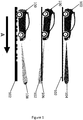
- Many vehicles today will use radar systems to provide information on the surrounding conditions, to detect other vehicles or pedestrians on the road, or other objects on the road the vehicle is travelling on. The radar can also be used to detect the overall conditions of the road the vehicle is travelling on. This is illustrated in
figure 1 . Generally, the radar is installed on the front and /or rear of thevehicle 100 and is generally positioned vertically with respect to the direction of travel of the vehicle, as the vehicle drives along theroad 102, (direction of travel shown by arrow A) the radar will project a beam at a known angle. Assuming that the vehicle is travelling on a flat surface, and thevehicle 100 maintains a stable position as it drives along the road, then the radar will have a standard known projection in front of thevehicle 104. When the rear of the vehicle is lower than the front (for example if the vehicle is carrying a heavy load at the rear) then the front of the vehicle will be higher than the rear, and so radar from the front of the vehicle will have an upward tilt. Conversely, if thevehicle 100 brakes sharply, the front of the vehicle will tilt downwards, and the radar from the front of the vehicle will have adownward tilt 106. In some cases, for example, if the vehicle is travelling along an uneven road surface, then the front of the vehicle will move up and down according to the road surface, and the angle of the radar beam from the front of the car will change as the surface of the road changes 108. These possible alternatives are shown infig. 1 . - As shown in
figure 1 , when thevehicle 100 brakes, there is a down tilt to the beam, whereas when the vehicle accelerates the tilt is upwards (not shown in the figure). As also shown infigure 1 the beam may tilt up and down in an arbitrary manner as the vehicle drives over an uneven road surface. The tilt will also vary according to the acceleration or braking speed, and may also be affected by the vehicle dimensions, spring of the tyre and other parameters related to the vehicle. However, these have less effect on the tilt that the speed. These "vehicle" parameters may vary between cars, for example a more expensive vehicle may have suspension that can compensate for uneven road surfaces, compared to more basic vehicles - Presently, there is a demand in the automotive industry to enable radar systems on the vehicles to perform elevation measurements that have good resolution. Current systems typically have a resolution of 1°.
- Movements of the vehicle as the vehicle is travelling e.g. due to bumpy roads, acceleration, breaking, may result in changes to the tilt of the transmitted radar signal. This applies to regular vehicles with a human driver as well as to autonomous driving vehicles. This may result in significant errors in the measured elevation angle of the radar signal. Travelling large distances may also exacerbate this problem. A small tilt in the radar beam can result in a significant difference in the measured elevation, and this will increase as the distance increases. For example, a 1.4 degree beam tilt over a distance of 200m will lead to a 5m difference in the measured height, whereas a 2.8degree beam tilt will give the same 5m difference in height, but at a distance of 100m.
- Examples of the present invention provide a radar device that can calculate and adjust the tilt in a beam angle due to movements of the vehicle, as described in the accompanying claims. Specific embodiments of the invention are set forth in the dependent claims. These and other aspects of the invention will be apparent from, and elucidated with reference to, the embodiments described hereinafter.
- Further details, aspects and embodiments of the invention will be described, by way of example only, with reference to the drawings. In the drawings, like reference numbers are used to identify like or functionally similar elements. Elements in the figures are illustrated for simplicity and clarity and have not necessarily been drawn to scale.
- Fig. 1
- illustrates examples of radar signals from vehicles driven under different conditions;
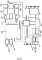
- Fig. 2
- illustrates an acceleration sensor that is used in the invention
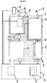
- Fig. 3
- is an example of the radar device of the invention;
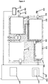
- Fig 4
- is an alternative example of the radar device of the invention
- Fig. 5
- is a flow chart illustrating the method of the invention.
- Because the illustrated example embodiments of the present invention may, for the most part, be implemented using electronic components and circuits known to those skilled in the art, details will not be explained in any greater extent than that considered necessary as illustrated below, for the understanding and appreciation of the underlying concepts of the present invention and in order not to obfuscate or distract from the teachings of the present invention.
- The inventors have recognised and appreciated that improved resolution of a radar device is desirable. As automotive radar sensors are developed, they will be required to have higher resolution, for example, the improved resolution may help to decide if it is possible for the vehicle to pass over an obstacle on the road. The obstacle may be a speed bump, a gully or drain cover. If an obstacle causes the radar beam to be tilted down towards the street due to the vehicle braking or the presence of a hole in the road, this could result in the vehicle undertaking emergency braking for example, or the vehicle slowing down which may affect the overall driving, or lead to delays on the journey, particularly for autonomous vehicles.
- Using acceleration measurements and radar information to correct the beam tilt, or obtain system information will result in overall improved system performance.
-
Figure 2 is an example of anacceleration sensor 200 that may be used in an embodiment of the invention. Theacceleration sensor 200 includesvoltage regulator 202,programmable data array 204,reference oscillator 206,primary oscillator 208,clock monitor 210,internal clock 212,control logic 214, serial peripheral interface (SPI) 216, pulse code modulator (PCM) 218, digital signal processor (DSP) 220,temperature sensor 222,sinc filters converters cells test interface 230. In an example of the invention theacceleration sensor 200 measures the acceleration of the radar sensor on the vehicle in the vertical direction, as the vehicle is moving, but in some examples, the sensor may measure the acceleration of the radar sensor in other directions with respect to the direction of movement of the vehicle. Generally, the acceleration will be measured at an angle between 30° to 150° to the direction of travel of the vehicle, or more particularly at an angle between 75° and 105°. In a further preferred example of the invention the acceleration is measured in a direction that is substantially vertical to the direction of travel of the vehicle. The measurement of the acceleration of the radar sensor or the vehicle chassis in the vertical direction for example, can be realized based on the principle of a differential capacitance arising from acceleration-induced motion of the radar sensor. -
Figure 3 is an illustration of an example of circuitry to implement an example of the invention that includes aradar 300 sensor,acceleration sensor 200,automotive radar microcontroller 350 that includesprocessor 320 andmemory 330. Theprocesser 320 may also include a calibration unit 322.Theradar sensor 300 includes areceiver array 302,receiver antenna 304,transmitter array 308, that includes a beam corrector 360 (in an example of the invention the beam corrector may be a beam steerer or a phase rotator),transmitter antenna 306,output array 310,chirp generator 312,internal balun 314,external balun 318, and bypass 316. Theacceleration sensor 200 is coupled to theautomotive radar microcontroller 350. The radar sensor generates a radio frequency that is transmitted, reflected by objects and afterwards received via the RX antennas. The received signals are mixed to a lower frequency and digitized for further processing in the Microcontroller. - In this example of the invention this circuitry uses a beam-corrector functionality to adjust and/or correct beam tilt error in the transmitted beam of the radar sensor caused by vehicle chassis movements. The calculated beam tilt of the sensor will be compared with a pre-set reference value for the beam tilt, and if the difference between these two measurements exceeds a pre-set threshold, the beam tilt will be adjusted to a pre-set value, to correct the beam tilt back to that required. In an embodiment of the invention the pre-set reference threshold may be set when the radar sensor is initially installed on the vehicle, or it may be changed at various times according to the driving conditions, or other external factors. The measured acceleration value is used to adjust the transmitted radar beam tilt using
beam corrector 360 in a phased-array antenna setup. In an example of the invention, it will be a simple relationship between the measured acceleration and the tilt angle, so that if the acceleration exceeds a value x, then the radar beam is corrected to angle y°. In an example of the invention, the greater the acceleration then the more the tilt angle is corrected. In addition, the relationship will also account for latency in the radar beam. -
Figure 4 shows the circuitry used in an alternative approach to correct the beam tilt. Like elements fromfigure 3 have been given the same reference numerals. In this example of the invention the circuitry does not include a beam corrector but instead information from theacceleration sensor 200 is processed using software within theautomotive radar microcontroller 350 to calculate the beam tilt, and the microcontroller will communicate withradar sensor 300 to correct the tilt of the radar beam, according to the comparison with the threshold value. - In an example of the invention the circuitry of
figures 3 and4 can operate to (i) correct radar beam elevation based on the measured acceleration of the radar sensor whilst the vehicle is in motion and/or(ii) to classify received radar data. Generally, the classified received data will be used for the subsequent correction of the radar beam tilt, but the classified data may also be used for other purposes, such as later software classification of the radar data. - In an example of the invention, the
acceleration sensor 200 will measure the vertical movement of theradar sensor 300 as the vehicle chassis is moving, for example due to the vehicle travelling over a bumpy road, the vehicle accelerating or breaking. Theacceleration sensor 200 may be directly coupled to theradar sensor 300, or may alternatively be mounted somewhere on the vehicle chassis to measure the acceleration of the chassis. The measured vertical acceleration can be used to correct the tilt of automotive radar beam in elevation due to vehicle chassis movements (e.g. bumpy road, acceleration, breaking) or to classify the received data during chassis movements. All the measured data will be stored inmemory 330 andprocessor 320 will analyse the measured data, and perform the beam correction and or data evaluation. - The
memory 330 ofautomotive radar microcontroller 350 will have details of the vertical tilt threshold that is used to determine if the beam angle of the radar needs to be corrected. The threshold may be calculated based on various parameters of the vehicle including the vehicle acceleration, and in some examples of the invention, the threshold may be dynamically adjusted according to the specific driving conditions at that time. Typically, the threshold is calculated in advance and stored in themicrocontroller 350. In operation of the radar sensor, the threshold is compared with the measured tilt angle as described above. - In an example of the invention, the tilt correction may be carried out as part of a calibration correction. In one example, the radar sensor for each vehicle will have been calibrated to a set standard at the production facility. The calibration may be for the vehicle software, in which case all vehicles in a specific production run will have the same calibration standard. In an example of the invention the calibration process may calibrate a correction factor against the measured acceleration value of the sensor. This can be done by measuring the beam tilt of the radar sensor against the measured acceleration. These measurements can then be used to correct the tilt back to the expected calibration measurement.
-
Figure 5 isflow chart 400 showing the steps in an example of the method of the invention. At 402 the vertical acceleration of the radar sensor on a vehicle is measured by the acceleration sensor, this output passes to 404 and the tilt of the radar beam extending from the vehicle that is due to the changing motion of the vehicle is calculated, at 406 the radar beam tilt is corrected back to the standard (by comparing the tilt with the vertical threshold limit that is stored in the microcontroller 350), or the tilt information is used to evaluate the radar data, and no adjustment of the radar beam occurs. This correction may be performed using the beam corrector, or the software control as discussed above. In an example of the invention, the tilt correction angle corr(t) is equal to measured vertical acceleration a(t)' multiplied by a correction factor m, added to a latency function f(t) as shown in equation 1 below:
- If 406 results in the correction of the radar beam tilt for example, by beam steering technologies, this correction may occur on either the transmitter or the receiver side of the
sensor 300. In an example of the invention, for correction on the transmission side, this will be a physical correction of the beam, using thephase rotator 360 for example as shown infigure 3 , whereas correction or adjustment of the radar beam on the receiver side will be via software control within theautomotive radar microcontroller 350, as shown infigure 4 . - If 406 is used to evaluate the measured radar acceleration, rather than correcting the tilt, then data may be used in software processing to evaluate/classify/weighting the sensor data. This can be used to improve the reliability of autonomous driving vehicles, as the evaluated data can be fed back into the development of autonomous vehicles.
- Although examples of the invention are described with reference to a radar unit suitable for an automotive application, it is envisaged that the concepts herein described may be applicable to other applications, such as; MR3003 Radar Transceiver, TEF810X Radar Transceiver; Microcontroller: S32R27: S32R Radar Microcontroller; MMA69XX Automotive Accelerometers.
- In the foregoing specification, the invention has been described with reference to specific examples of embodiments of the invention. It will, however, be evident that various modifications and changes may be made therein without departing from the scope of the invention as set forth in the appended claims and that the claims are not limited to the specific examples described above. The connections as discussed herein may be any type of connection suitable to transfer signals from or to the respective nodes, units or integrated circuit devices. Accordingly, unless implied or stated otherwise, the connections may for example be direct connections or indirect connections. Also, plurality of connections may be replaced with a single connection that transfers multiple signals serially or in a time multiplexed manner. Likewise, single connections carrying multiple signals may be separated out into various different connections carrying subsets of these signals. Therefore, many options exist for transferring signals.
- Those skilled in the art will recognize that the architectures depicted herein are merely exemplary, and that in fact many other architectures can be implemented which achieve the same functionality. Any arrangement of components to achieve the same functionality is effectively 'associated' such that the desired functionality is achieved. Hence, any two components herein combined to achieve a particular functionality can be seen as associated with' each other such that the desired functionality is achieved, irrespective of architectures or intermediary components. Likewise, any two components so associated can also be viewed as being 'operably connected,' or 'operably coupled,' to each other to achieve the desired functionality.
- Furthermore, those skilled in the art will recognize that boundaries between the above described operations merely illustrative. The multiple operations may be combined into a single operation, a single operation may be distributed in additional operations and operations may be executed at least partially overlapping in time. Moreover, alternative embodiments may include multiple instances of a particular operation, and the order of operations may be altered in various other embodiments.
- In the claims, any reference signs placed between parentheses shall not be construed as limiting the claim. The word 'comprising' does not exclude the presence of other elements or steps then those listed in a claim. Furthermore, the terms 'a' or 'an,' as used herein, are defined as one, or more than one. Also, the use of introductory phrases such as 'at least one' and 'one or more' in the claims should not be construed to imply that the introduction of another claim element by the indefinite articles 'a' or 'an' limits any particular claim containing such introduced claim element to inventions containing only one such element, even when the same claim includes the introductory phrases 'one or more' or 'at least one' and indefinite articles such as 'a' or 'an.' The same holds true for the use of definite articles. Unless stated otherwise, terms such as 'first' and 'second' are used to arbitrarily distinguish between the elements such terms describe. Thus, these terms are not necessarily intended to indicate temporal or other prioritization of such elements. The mere fact that certain measures are recited in mutually different claims does not indicate that a combination of these measures cannot be used to advantage.
Claims (15)
- A radar sensor (300) for use in a vehicle comprising:at least one transmitter (308) and at least once receiver (302) to transmit and receive radar signals of the radar sensor (300);an acceleration sensor (200) to measure the acceleration of said radar sensor (300) or the vehicle;a processor (320) coupled to said acceleration sensor (200) to calculate a tilt in a radar signal projected from said vehicle using said measured acceleration;a memory (330) for storing said calculated radar tilt;wherein said sensor (300) can process said measured acceleration and either adjust the tilt of said radar signal in response to said measured acceleration or classify the measured data.
- A radar sensor (300) according to any preceding claim wherein said acceleration sensor (200) is coupled to said transmitter (308) of said radar sensor (300).
- A radar sensor (300) according to claim 1 or claim 2 wherein said acceleration sensor (200) measures the acceleration of said radar sensor (300) in a direction that is at an angle between 30° to 150° to the direction of travel in the vehicle.
- A radar sensor according to claim 3 wherein the direction of the acceleration sensor is at angle between 75° and 105° to the direction of travel.
- A radar sensor (300) according to any preceding claim further comprising a beam corrector (360), wherein said beam corrector (360) will compare said calculated radar tilt with a pre-set reference tilt and adjust said tilt to a pre-set value if the difference between the pre-set value and the reference value exceeds a set threshold.
- A radar sensor according to claim 5 wherein the threshold is dynamically adjusted based on driving conditions.
- A radar sensor according to claim 5 or claim 6 wherein said beam corrector is a beam steerer or a phase rotator (360).
- A radar sensor according to claim 7 wherein said beam corrector is within said at least one transmitter (308).
- A radar sensor according to any of claims 1 to 4 wherein the tilt of the radar signal is adjusted in the receiver via software control.
- A radar sensor according to any preceding claim further comprising a calibration unit (322) to calibrate the radar signal.
- A radar sensor according to claim 8 wherein said calibration unit (322) is within said processor(320)
- A radar unit according to any claims 1 to 4 wherein said processor can process the classified data from said radar signal in combination with said calculated radar tilt.
- A method for adjusting a radar signal transmitted from a vehicle comprising:transmitting a radar signal from said vehicle;measuring the acceleration of said vehicle;using said measured acceleration to calculate a tilt of said radar signal;comparing said calculated tilt with a stored reference tilt;adjusting the tilt of said radar signal if said comparison of the calculated and reference tilt exceeds a predetermined value.
- A method according to claim 12 or claim 13 wherein said radar signal is adjusted using a phase rotator.
- A method according to claim 12 or 13 wherein said radar signal is adjusted using software.
Priority Applications (3)
| Application Number | Priority Date | Filing Date | Title |
|---|---|---|---|
| EP18190464.0A EP3614167B1 (en) | 2018-08-23 | 2018-08-23 | Vehicle radar sensor and method of operation |
| US16/385,518 US11194018B2 (en) | 2018-08-23 | 2019-04-16 | Vehicle radar sensor and method of operation |
| CN201910781040.7A CN110895328B (en) | 2018-08-23 | 2019-08-23 | Vehicle radar sensor and method of operation |
Applications Claiming Priority (1)
| Application Number | Priority Date | Filing Date | Title |
|---|---|---|---|
| EP18190464.0A EP3614167B1 (en) | 2018-08-23 | 2018-08-23 | Vehicle radar sensor and method of operation |
Publications (2)
| Publication Number | Publication Date |
|---|---|
| EP3614167A1 true EP3614167A1 (en) | 2020-02-26 |
| EP3614167B1 EP3614167B1 (en) | 2022-07-20 |
Family
ID=63371566
Family Applications (1)
| Application Number | Title | Priority Date | Filing Date |
|---|---|---|---|
| EP18190464.0A Active EP3614167B1 (en) | 2018-08-23 | 2018-08-23 | Vehicle radar sensor and method of operation |
Country Status (3)
| Country | Link |
|---|---|
| US (1) | US11194018B2 (en) |
| EP (1) | EP3614167B1 (en) |
| CN (1) | CN110895328B (en) |
Cited By (2)
| Publication number | Priority date | Publication date | Assignee | Title |
|---|---|---|---|---|
| CN116087898A (en) * | 2023-01-03 | 2023-05-09 | 上海仁昊电子科技有限公司 | Inertial navigation compensation method for radar speed measurement and radar speed measurement system for inertial navigation compensation |
| DE102023107272A1 (en) * | 2023-03-23 | 2024-09-26 | Valeo Schalter Und Sensoren Gmbh | Sensor device and method for mounting a sensor device in a vehicle |
Families Citing this family (5)
| Publication number | Priority date | Publication date | Assignee | Title |
|---|---|---|---|---|
| DE102019214544B4 (en) * | 2019-09-24 | 2022-04-28 | Vitesco Technologies GmbH | Method and device for determining a target position of an environment sensor of a vehicle |
| CN112285717B (en) * | 2020-10-29 | 2024-08-06 | 腾讯科技(深圳)有限公司 | Method for controlling vehicle-mounted radar signal and electronic equipment |
| CN112269178A (en) * | 2020-11-24 | 2021-01-26 | 珠海上富电技股份有限公司 | A millimeter-wave radar with an acceleration sensor, a motor vehicle and a method for calculating the speed of the vehicle |
| CN114690132A (en) * | 2020-12-31 | 2022-07-01 | 北汽福田汽车股份有限公司 | Vehicle-mounted radar calibration method and device, storage medium and vehicle |
| US20240045051A1 (en) * | 2022-08-04 | 2024-02-08 | Honeywell International Inc. | Multi-beam radar based ground speed sensor utilizing a single radar integrated circuit |
Citations (3)
| Publication number | Priority date | Publication date | Assignee | Title |
|---|---|---|---|---|
| US20130154870A1 (en) * | 2011-12-14 | 2013-06-20 | Ford Global Technologies, Llc | Internal multi-axis g sensing used to align an automotive forward radar to the vehicle's thrust axis |
| US20160003938A1 (en) * | 2014-07-03 | 2016-01-07 | GM Global Technology Operations LLC | Vehicle radar with beam adjustment |
| DE102016207213A1 (en) * | 2016-04-28 | 2017-11-02 | Robert Bosch Gmbh | Radar system, method for operating a radar system and vehicle with a radar system |
Family Cites Families (10)
| Publication number | Priority date | Publication date | Assignee | Title |
|---|---|---|---|---|
| EP1130416A3 (en) | 2000-03-02 | 2002-01-30 | Denso Corporation | Forward condition detecting apparatus for vehicles |
| JP4895484B2 (en) * | 2004-06-28 | 2012-03-14 | 富士通テン株式会社 | Axis deviation calculation method for on-vehicle radar device and on-vehicle radar axis deviation determination method |
| DE102008038365A1 (en) | 2008-07-02 | 2010-01-07 | Adc Automotive Distance Control Systems Gmbh | Vehicle radar system and method for determining a position of at least one object relative to a vehicle |
| JP2010243219A (en) * | 2009-04-01 | 2010-10-28 | Fujitsu Ten Ltd | Radar device and radar adjusting method |
| US20130154871A1 (en) * | 2011-12-14 | 2013-06-20 | Ford Global Technologies, Llc | Tilt sensing system for automotive radar |
| WO2014002210A1 (en) * | 2012-06-27 | 2014-01-03 | 三菱電機株式会社 | Positioning device |
| US9423498B1 (en) * | 2012-09-25 | 2016-08-23 | Google Inc. | Use of motion data in the processing of automotive radar image processing |
| DE102013208735A1 (en) * | 2013-05-13 | 2014-11-13 | Robert Bosch Gmbh | Method and device for determining and compensating for a misalignment angle of a radar sensor of a vehicle |
| US20150070207A1 (en) * | 2013-09-06 | 2015-03-12 | Valeo Radar Systems, Inc. | Method and Apparatus For Self Calibration of A Vehicle Radar System |
| WO2016003473A1 (en) * | 2014-07-03 | 2016-01-07 | GM Global Technology Operations LLC | Vehicle radar methods and systems |
-
2018
- 2018-08-23 EP EP18190464.0A patent/EP3614167B1/en active Active
-
2019
- 2019-04-16 US US16/385,518 patent/US11194018B2/en not_active Expired - Fee Related
- 2019-08-23 CN CN201910781040.7A patent/CN110895328B/en active Active
Patent Citations (3)
| Publication number | Priority date | Publication date | Assignee | Title |
|---|---|---|---|---|
| US20130154870A1 (en) * | 2011-12-14 | 2013-06-20 | Ford Global Technologies, Llc | Internal multi-axis g sensing used to align an automotive forward radar to the vehicle's thrust axis |
| US20160003938A1 (en) * | 2014-07-03 | 2016-01-07 | GM Global Technology Operations LLC | Vehicle radar with beam adjustment |
| DE102016207213A1 (en) * | 2016-04-28 | 2017-11-02 | Robert Bosch Gmbh | Radar system, method for operating a radar system and vehicle with a radar system |
Cited By (2)
| Publication number | Priority date | Publication date | Assignee | Title |
|---|---|---|---|---|
| CN116087898A (en) * | 2023-01-03 | 2023-05-09 | 上海仁昊电子科技有限公司 | Inertial navigation compensation method for radar speed measurement and radar speed measurement system for inertial navigation compensation |
| DE102023107272A1 (en) * | 2023-03-23 | 2024-09-26 | Valeo Schalter Und Sensoren Gmbh | Sensor device and method for mounting a sensor device in a vehicle |
Also Published As
| Publication number | Publication date |
|---|---|
| EP3614167B1 (en) | 2022-07-20 |
| US20200110153A1 (en) | 2020-04-09 |
| CN110895328B (en) | 2024-12-13 |
| CN110895328A (en) | 2020-03-20 |
| US11194018B2 (en) | 2021-12-07 |
Similar Documents
| Publication | Publication Date | Title |
|---|---|---|
| US11194018B2 (en) | Vehicle radar sensor and method of operation | |
| US11346933B2 (en) | Doppler ambiguity resolution in MIMO radars using a SIMO evaluation | |
| Steinbaeck et al. | Next generation radar sensors in automotive sensor fusion systems | |
| US20200124447A1 (en) | Vehicle Sensor Field Calibration Utilizing Other Vehicles | |
| JP2023126371A (en) | Electronic equipment, electronic equipment control method, and electronic equipment control program | |
| US20160178742A1 (en) | Radar apparatus and radar state estimation method | |
| CN114814805A (en) | Radar system for detecting angles in bi-static and mono-static scenarios | |
| EP3943980A1 (en) | Electronic device, electronic device control method, and electronic device control program | |
| US10473760B2 (en) | Radar device and vertical axis-misalignment detecting method | |
| EP4490539A1 (en) | Radar systems for determining vehicle speed over ground | |
| JP2021073452A (en) | Electronic device, electronic device control method, and electronic device control program | |
| CN112020659A (en) | Electronic device, control method for electronic device, and control program for electronic device | |
| JP2004085258A (en) | Radar equipment | |
| EP4043910B1 (en) | Electronic apparatus, control method for electronic apparatus, and control program for electronic apparatus | |
| US20240369700A1 (en) | Electronic device, method for controlling electronic device, and program | |
| JP2012021893A (en) | Rear-end collision prevention device using sensor | |
| JP7412520B2 (en) | Electronic equipment, electronic equipment control method, and electronic equipment control program | |
| US20180284221A1 (en) | Radar apparatus | |
| EP3508873B1 (en) | Measuring device, control device, control method, and program | |
| WO2022030560A1 (en) | Electronic device, method for controlling electronic device, and program | |
| EP4155771A1 (en) | Electronic device, electronic device control method, and program | |
| CN113795767A (en) | Electronic device, control method for electronic device, and program | |
| JP7588018B2 (en) | Electronics | |
| US12578454B2 (en) | Ego velocity assisted direction of arrival estimator for radar systems | |
| WO2024158581A1 (en) | Systems and methods for enhancing ground speed determination for a vehicle |
Legal Events
| Date | Code | Title | Description |
|---|---|---|---|
| PUAI | Public reference made under article 153(3) epc to a published international application that has entered the european phase |
Free format text: ORIGINAL CODE: 0009012 |
|
| STAA | Information on the status of an ep patent application or granted ep patent |
Free format text: STATUS: THE APPLICATION HAS BEEN PUBLISHED |
|
| AK | Designated contracting states |
Kind code of ref document: A1 Designated state(s): AL AT BE BG CH CY CZ DE DK EE ES FI FR GB GR HR HU IE IS IT LI LT LU LV MC MK MT NL NO PL PT RO RS SE SI SK SM TR |
|
| AX | Request for extension of the european patent |
Extension state: BA ME |
|
| STAA | Information on the status of an ep patent application or granted ep patent |
Free format text: STATUS: REQUEST FOR EXAMINATION WAS MADE |
|
| 17P | Request for examination filed |
Effective date: 20200826 |
|
| RBV | Designated contracting states (corrected) |
Designated state(s): AL AT BE BG CH CY CZ DE DK EE ES FI FR GB GR HR HU IE IS IT LI LT LU LV MC MK MT NL NO PL PT RO RS SE SI SK SM TR |
|
| RIC1 | Information provided on ipc code assigned before grant |
Ipc: G01S 13/931 20200101ALI20220228BHEP Ipc: G01S 13/86 20060101ALI20220228BHEP Ipc: G01S 7/40 20060101AFI20220228BHEP |
|
| GRAP | Despatch of communication of intention to grant a patent |
Free format text: ORIGINAL CODE: EPIDOSNIGR1 |
|
| STAA | Information on the status of an ep patent application or granted ep patent |
Free format text: STATUS: GRANT OF PATENT IS INTENDED |
|
| INTG | Intention to grant announced |
Effective date: 20220420 |
|
| GRAS | Grant fee paid |
Free format text: ORIGINAL CODE: EPIDOSNIGR3 |
|
| GRAA | (expected) grant |
Free format text: ORIGINAL CODE: 0009210 |
|
| STAA | Information on the status of an ep patent application or granted ep patent |
Free format text: STATUS: THE PATENT HAS BEEN GRANTED |
|
| AK | Designated contracting states |
Kind code of ref document: B1 Designated state(s): AL AT BE BG CH CY CZ DE DK EE ES FI FR GB GR HR HU IE IS IT LI LT LU LV MC MK MT NL NO PL PT RO RS SE SI SK SM TR |
|
| REG | Reference to a national code |
Ref country code: CH Ref legal event code: EP |
|
| REG | Reference to a national code |
Ref country code: DE Ref legal event code: R096 Ref document number: 602018038058 Country of ref document: DE |
|
| REG | Reference to a national code |
Ref country code: AT Ref legal event code: REF Ref document number: 1505870 Country of ref document: AT Kind code of ref document: T Effective date: 20220815 |
|
| REG | Reference to a national code |
Ref country code: IE Ref legal event code: FG4D |
|
| REG | Reference to a national code |
Ref country code: LT Ref legal event code: MG9D |
|
| REG | Reference to a national code |
Ref country code: NL Ref legal event code: MP Effective date: 20220720 |
|
| PG25 | Lapsed in a contracting state [announced via postgrant information from national office to epo] |
Ref country code: SE Free format text: LAPSE BECAUSE OF FAILURE TO SUBMIT A TRANSLATION OF THE DESCRIPTION OR TO PAY THE FEE WITHIN THE PRESCRIBED TIME-LIMIT Effective date: 20220720 Ref country code: RS Free format text: LAPSE BECAUSE OF FAILURE TO SUBMIT A TRANSLATION OF THE DESCRIPTION OR TO PAY THE FEE WITHIN THE PRESCRIBED TIME-LIMIT Effective date: 20220720 Ref country code: PT Free format text: LAPSE BECAUSE OF FAILURE TO SUBMIT A TRANSLATION OF THE DESCRIPTION OR TO PAY THE FEE WITHIN THE PRESCRIBED TIME-LIMIT Effective date: 20221121 Ref country code: NO Free format text: LAPSE BECAUSE OF FAILURE TO SUBMIT A TRANSLATION OF THE DESCRIPTION OR TO PAY THE FEE WITHIN THE PRESCRIBED TIME-LIMIT Effective date: 20221020 Ref country code: NL Free format text: LAPSE BECAUSE OF FAILURE TO SUBMIT A TRANSLATION OF THE DESCRIPTION OR TO PAY THE FEE WITHIN THE PRESCRIBED TIME-LIMIT Effective date: 20220720 Ref country code: LV Free format text: LAPSE BECAUSE OF FAILURE TO SUBMIT A TRANSLATION OF THE DESCRIPTION OR TO PAY THE FEE WITHIN THE PRESCRIBED TIME-LIMIT Effective date: 20220720 Ref country code: LT Free format text: LAPSE BECAUSE OF FAILURE TO SUBMIT A TRANSLATION OF THE DESCRIPTION OR TO PAY THE FEE WITHIN THE PRESCRIBED TIME-LIMIT Effective date: 20220720 Ref country code: FI Free format text: LAPSE BECAUSE OF FAILURE TO SUBMIT A TRANSLATION OF THE DESCRIPTION OR TO PAY THE FEE WITHIN THE PRESCRIBED TIME-LIMIT Effective date: 20220720 Ref country code: ES Free format text: LAPSE BECAUSE OF FAILURE TO SUBMIT A TRANSLATION OF THE DESCRIPTION OR TO PAY THE FEE WITHIN THE PRESCRIBED TIME-LIMIT Effective date: 20220720 |
|
| REG | Reference to a national code |
Ref country code: AT Ref legal event code: MK05 Ref document number: 1505870 Country of ref document: AT Kind code of ref document: T Effective date: 20220720 |
|
| PG25 | Lapsed in a contracting state [announced via postgrant information from national office to epo] |
Ref country code: PL Free format text: LAPSE BECAUSE OF FAILURE TO SUBMIT A TRANSLATION OF THE DESCRIPTION OR TO PAY THE FEE WITHIN THE PRESCRIBED TIME-LIMIT Effective date: 20220720 Ref country code: IS Free format text: LAPSE BECAUSE OF FAILURE TO SUBMIT A TRANSLATION OF THE DESCRIPTION OR TO PAY THE FEE WITHIN THE PRESCRIBED TIME-LIMIT Effective date: 20221120 Ref country code: HR Free format text: LAPSE BECAUSE OF FAILURE TO SUBMIT A TRANSLATION OF THE DESCRIPTION OR TO PAY THE FEE WITHIN THE PRESCRIBED TIME-LIMIT Effective date: 20220720 Ref country code: GR Free format text: LAPSE BECAUSE OF FAILURE TO SUBMIT A TRANSLATION OF THE DESCRIPTION OR TO PAY THE FEE WITHIN THE PRESCRIBED TIME-LIMIT Effective date: 20221021 |
|
| REG | Reference to a national code |
Ref country code: CH Ref legal event code: PL |
|
| REG | Reference to a national code |
Ref country code: DE Ref legal event code: R097 Ref document number: 602018038058 Country of ref document: DE |
|
| PG25 | Lapsed in a contracting state [announced via postgrant information from national office to epo] |
Ref country code: SM Free format text: LAPSE BECAUSE OF FAILURE TO SUBMIT A TRANSLATION OF THE DESCRIPTION OR TO PAY THE FEE WITHIN THE PRESCRIBED TIME-LIMIT Effective date: 20220720 Ref country code: RO Free format text: LAPSE BECAUSE OF FAILURE TO SUBMIT A TRANSLATION OF THE DESCRIPTION OR TO PAY THE FEE WITHIN THE PRESCRIBED TIME-LIMIT Effective date: 20220720 Ref country code: MC Free format text: LAPSE BECAUSE OF FAILURE TO SUBMIT A TRANSLATION OF THE DESCRIPTION OR TO PAY THE FEE WITHIN THE PRESCRIBED TIME-LIMIT Effective date: 20220720 Ref country code: LU Free format text: LAPSE BECAUSE OF NON-PAYMENT OF DUE FEES Effective date: 20220823 Ref country code: LI Free format text: LAPSE BECAUSE OF NON-PAYMENT OF DUE FEES Effective date: 20220831 Ref country code: DK Free format text: LAPSE BECAUSE OF FAILURE TO SUBMIT A TRANSLATION OF THE DESCRIPTION OR TO PAY THE FEE WITHIN THE PRESCRIBED TIME-LIMIT Effective date: 20220720 Ref country code: CZ Free format text: LAPSE BECAUSE OF FAILURE TO SUBMIT A TRANSLATION OF THE DESCRIPTION OR TO PAY THE FEE WITHIN THE PRESCRIBED TIME-LIMIT Effective date: 20220720 Ref country code: CH Free format text: LAPSE BECAUSE OF NON-PAYMENT OF DUE FEES Effective date: 20220831 Ref country code: AT Free format text: LAPSE BECAUSE OF FAILURE TO SUBMIT A TRANSLATION OF THE DESCRIPTION OR TO PAY THE FEE WITHIN THE PRESCRIBED TIME-LIMIT Effective date: 20220720 |
|
| REG | Reference to a national code |
Ref country code: BE Ref legal event code: MM Effective date: 20220831 |
|
| PLBE | No opposition filed within time limit |
Free format text: ORIGINAL CODE: 0009261 |
|
| STAA | Information on the status of an ep patent application or granted ep patent |
Free format text: STATUS: NO OPPOSITION FILED WITHIN TIME LIMIT |
|
| PG25 | Lapsed in a contracting state [announced via postgrant information from national office to epo] |
Ref country code: SK Free format text: LAPSE BECAUSE OF FAILURE TO SUBMIT A TRANSLATION OF THE DESCRIPTION OR TO PAY THE FEE WITHIN THE PRESCRIBED TIME-LIMIT Effective date: 20220720 Ref country code: EE Free format text: LAPSE BECAUSE OF FAILURE TO SUBMIT A TRANSLATION OF THE DESCRIPTION OR TO PAY THE FEE WITHIN THE PRESCRIBED TIME-LIMIT Effective date: 20220720 |
|
| 26N | No opposition filed |
Effective date: 20230421 |
|
| GBPC | Gb: european patent ceased through non-payment of renewal fee |
Effective date: 20221020 |
|
| PG25 | Lapsed in a contracting state [announced via postgrant information from national office to epo] |
Ref country code: AL Free format text: LAPSE BECAUSE OF FAILURE TO SUBMIT A TRANSLATION OF THE DESCRIPTION OR TO PAY THE FEE WITHIN THE PRESCRIBED TIME-LIMIT Effective date: 20220720 |
|
| PG25 | Lapsed in a contracting state [announced via postgrant information from national office to epo] |
Ref country code: IE Free format text: LAPSE BECAUSE OF NON-PAYMENT OF DUE FEES Effective date: 20220823 |
|
| P01 | Opt-out of the competence of the unified patent court (upc) registered |
Effective date: 20230725 |
|
| PG25 | Lapsed in a contracting state [announced via postgrant information from national office to epo] |
Ref country code: SI Free format text: LAPSE BECAUSE OF FAILURE TO SUBMIT A TRANSLATION OF THE DESCRIPTION OR TO PAY THE FEE WITHIN THE PRESCRIBED TIME-LIMIT Effective date: 20220720 |
|
| PG25 | Lapsed in a contracting state [announced via postgrant information from national office to epo] |
Ref country code: BE Free format text: LAPSE BECAUSE OF NON-PAYMENT OF DUE FEES Effective date: 20220831 |
|
| PG25 | Lapsed in a contracting state [announced via postgrant information from national office to epo] |
Ref country code: GB Free format text: LAPSE BECAUSE OF NON-PAYMENT OF DUE FEES Effective date: 20221020 |
|
| PG25 | Lapsed in a contracting state [announced via postgrant information from national office to epo] |
Ref country code: HU Free format text: LAPSE BECAUSE OF FAILURE TO SUBMIT A TRANSLATION OF THE DESCRIPTION OR TO PAY THE FEE WITHIN THE PRESCRIBED TIME-LIMIT; INVALID AB INITIO Effective date: 20180823 |
|
| PG25 | Lapsed in a contracting state [announced via postgrant information from national office to epo] |
Ref country code: CY Free format text: LAPSE BECAUSE OF FAILURE TO SUBMIT A TRANSLATION OF THE DESCRIPTION OR TO PAY THE FEE WITHIN THE PRESCRIBED TIME-LIMIT Effective date: 20220720 |
|
| PG25 | Lapsed in a contracting state [announced via postgrant information from national office to epo] |
Ref country code: MK Free format text: LAPSE BECAUSE OF FAILURE TO SUBMIT A TRANSLATION OF THE DESCRIPTION OR TO PAY THE FEE WITHIN THE PRESCRIBED TIME-LIMIT Effective date: 20220720 Ref country code: IT Free format text: LAPSE BECAUSE OF FAILURE TO SUBMIT A TRANSLATION OF THE DESCRIPTION OR TO PAY THE FEE WITHIN THE PRESCRIBED TIME-LIMIT Effective date: 20220720 |
|
| PG25 | Lapsed in a contracting state [announced via postgrant information from national office to epo] |
Ref country code: BG Free format text: LAPSE BECAUSE OF FAILURE TO SUBMIT A TRANSLATION OF THE DESCRIPTION OR TO PAY THE FEE WITHIN THE PRESCRIBED TIME-LIMIT Effective date: 20220720 |
|
| PG25 | Lapsed in a contracting state [announced via postgrant information from national office to epo] |
Ref country code: MT Free format text: LAPSE BECAUSE OF FAILURE TO SUBMIT A TRANSLATION OF THE DESCRIPTION OR TO PAY THE FEE WITHIN THE PRESCRIBED TIME-LIMIT Effective date: 20220720 |
|
| PGFP | Annual fee paid to national office [announced via postgrant information from national office to epo] |
Ref country code: DE Payment date: 20240723 Year of fee payment: 7 |
|
| PGFP | Annual fee paid to national office [announced via postgrant information from national office to epo] |
Ref country code: FR Payment date: 20240723 Year of fee payment: 7 |
|
| PG25 | Lapsed in a contracting state [announced via postgrant information from national office to epo] |
Ref country code: TR Free format text: LAPSE BECAUSE OF FAILURE TO SUBMIT A TRANSLATION OF THE DESCRIPTION OR TO PAY THE FEE WITHIN THE PRESCRIBED TIME-LIMIT Effective date: 20220720 |
|
| REG | Reference to a national code |
Ref country code: DE Ref legal event code: R119 Ref document number: 602018038058 Country of ref document: DE |