EP3614165B1 - Angle of arrival estimation method and device - Google Patents
Angle of arrival estimation method and device Download PDFInfo
- Publication number
- EP3614165B1 EP3614165B1 EP19193257.3A EP19193257A EP3614165B1 EP 3614165 B1 EP3614165 B1 EP 3614165B1 EP 19193257 A EP19193257 A EP 19193257A EP 3614165 B1 EP3614165 B1 EP 3614165B1
- Authority
- EP
- European Patent Office
- Prior art keywords
- csi
- message
- signal
- antenna
- vectors
- Prior art date
- Legal status (The legal status is an assumption and is not a legal conclusion. Google has not performed a legal analysis and makes no representation as to the accuracy of the status listed.)
- Active
Links
Images



Classifications
-
- G—PHYSICS
- G01—MEASURING; TESTING
- G01S—RADIO DIRECTION-FINDING; RADIO NAVIGATION; DETERMINING DISTANCE OR VELOCITY BY USE OF RADIO WAVES; LOCATING OR PRESENCE-DETECTING BY USE OF THE REFLECTION OR RERADIATION OF RADIO WAVES; ANALOGOUS ARRANGEMENTS USING OTHER WAVES
- G01S3/00—Direction-finders for determining the direction from which infrasonic, sonic, ultrasonic or electromagnetic waves, or particle emission, not having a directional significance, are being received
- G01S3/02—Direction-finders for determining the direction from which infrasonic, sonic, ultrasonic or electromagnetic waves, or particle emission, not having a directional significance, are being received using radio waves
- G01S3/04—Details
- G01S3/12—Means for determining sense of direction, e.g. by combining signals from directional antenna or goniometer search coil with those from non-directional antenna
-
- H—ELECTRICITY
- H04—ELECTRIC COMMUNICATION TECHNIQUE
- H04W—WIRELESS COMMUNICATION NETWORKS
- H04W64/00—Locating users or terminals or network equipment for network management purposes, e.g. mobility management
- H04W64/006—Locating users or terminals or network equipment for network management purposes, e.g. mobility management with additional information processing, e.g. for direction or speed determination
-
- G—PHYSICS
- G01—MEASURING; TESTING
- G01S—RADIO DIRECTION-FINDING; RADIO NAVIGATION; DETERMINING DISTANCE OR VELOCITY BY USE OF RADIO WAVES; LOCATING OR PRESENCE-DETECTING BY USE OF THE REFLECTION OR RERADIATION OF RADIO WAVES; ANALOGOUS ARRANGEMENTS USING OTHER WAVES
- G01S3/00—Direction-finders for determining the direction from which infrasonic, sonic, ultrasonic or electromagnetic waves, or particle emission, not having a directional significance, are being received
- G01S3/02—Direction-finders for determining the direction from which infrasonic, sonic, ultrasonic or electromagnetic waves, or particle emission, not having a directional significance, are being received using radio waves
- G01S3/14—Systems for determining direction or deviation from predetermined direction
- G01S3/46—Systems for determining direction or deviation from predetermined direction using antennas spaced apart and measuring phase or time difference between signals therefrom, i.e. path-difference systems
- G01S3/48—Systems for determining direction or deviation from predetermined direction using antennas spaced apart and measuring phase or time difference between signals therefrom, i.e. path-difference systems the waves arriving at the antennas being continuous or intermittent and the phase difference of signals derived therefrom being measured
-
- G—PHYSICS
- G01—MEASURING; TESTING
- G01S—RADIO DIRECTION-FINDING; RADIO NAVIGATION; DETERMINING DISTANCE OR VELOCITY BY USE OF RADIO WAVES; LOCATING OR PRESENCE-DETECTING BY USE OF THE REFLECTION OR RERADIATION OF RADIO WAVES; ANALOGOUS ARRANGEMENTS USING OTHER WAVES
- G01S11/00—Systems for determining distance or velocity not using reflection or reradiation
- G01S11/02—Systems for determining distance or velocity not using reflection or reradiation using radio waves
-
- G—PHYSICS
- G01—MEASURING; TESTING
- G01S—RADIO DIRECTION-FINDING; RADIO NAVIGATION; DETERMINING DISTANCE OR VELOCITY BY USE OF RADIO WAVES; LOCATING OR PRESENCE-DETECTING BY USE OF THE REFLECTION OR RERADIATION OF RADIO WAVES; ANALOGOUS ARRANGEMENTS USING OTHER WAVES
- G01S3/00—Direction-finders for determining the direction from which infrasonic, sonic, ultrasonic or electromagnetic waves, or particle emission, not having a directional significance, are being received
- G01S3/02—Direction-finders for determining the direction from which infrasonic, sonic, ultrasonic or electromagnetic waves, or particle emission, not having a directional significance, are being received using radio waves
- G01S3/04—Details
- G01S3/10—Means for reducing or compensating for quadrantal, site, or like errors
-
- G—PHYSICS
- G01—MEASURING; TESTING
- G01S—RADIO DIRECTION-FINDING; RADIO NAVIGATION; DETERMINING DISTANCE OR VELOCITY BY USE OF RADIO WAVES; LOCATING OR PRESENCE-DETECTING BY USE OF THE REFLECTION OR RERADIATION OF RADIO WAVES; ANALOGOUS ARRANGEMENTS USING OTHER WAVES
- G01S3/00—Direction-finders for determining the direction from which infrasonic, sonic, ultrasonic or electromagnetic waves, or particle emission, not having a directional significance, are being received
- G01S3/02—Direction-finders for determining the direction from which infrasonic, sonic, ultrasonic or electromagnetic waves, or particle emission, not having a directional significance, are being received using radio waves
- G01S3/14—Systems for determining direction or deviation from predetermined direction
- G01S3/46—Systems for determining direction or deviation from predetermined direction using antennas spaced apart and measuring phase or time difference between signals therefrom, i.e. path-difference systems
- G01S3/50—Systems for determining direction or deviation from predetermined direction using antennas spaced apart and measuring phase or time difference between signals therefrom, i.e. path-difference systems the waves arriving at the antennas being pulse modulated and the time difference of their arrival being measured
-
- G—PHYSICS
- G01—MEASURING; TESTING
- G01S—RADIO DIRECTION-FINDING; RADIO NAVIGATION; DETERMINING DISTANCE OR VELOCITY BY USE OF RADIO WAVES; LOCATING OR PRESENCE-DETECTING BY USE OF THE REFLECTION OR RERADIATION OF RADIO WAVES; ANALOGOUS ARRANGEMENTS USING OTHER WAVES
- G01S5/00—Position-fixing by co-ordinating two or more direction or position line determinations; Position-fixing by co-ordinating two or more distance determinations
- G01S5/18—Position-fixing by co-ordinating two or more direction or position line determinations; Position-fixing by co-ordinating two or more distance determinations using ultrasonic, sonic or infrasonic waves
- G01S5/28—Position-fixing by co-ordinating two or more direction or position line determinations; Position-fixing by co-ordinating two or more distance determinations using ultrasonic, sonic or infrasonic waves by co-ordinating position lines of different shape, e.g. hyperbolic, circular, elliptical or radial
-
- H—ELECTRICITY
- H04—ELECTRIC COMMUNICATION TECHNIQUE
- H04B—TRANSMISSION
- H04B7/00—Radio transmission systems, i.e. using radiation field
- H04B7/02—Diversity systems; Multi-antenna system, i.e. transmission or reception using multiple antennas
- H04B7/04—Diversity systems; Multi-antenna system, i.e. transmission or reception using multiple antennas using two or more spaced independent antennas
- H04B7/06—Diversity systems; Multi-antenna system, i.e. transmission or reception using multiple antennas using two or more spaced independent antennas at the transmitting station
- H04B7/0613—Diversity systems; Multi-antenna system, i.e. transmission or reception using multiple antennas using two or more spaced independent antennas at the transmitting station using simultaneous transmission
- H04B7/0615—Diversity systems; Multi-antenna system, i.e. transmission or reception using multiple antennas using two or more spaced independent antennas at the transmitting station using simultaneous transmission of weighted versions of same signal
- H04B7/0619—Diversity systems; Multi-antenna system, i.e. transmission or reception using multiple antennas using two or more spaced independent antennas at the transmitting station using simultaneous transmission of weighted versions of same signal using feedback from receiving side
- H04B7/0621—Feedback content
- H04B7/0626—Channel coefficients, e.g. channel state information [CSI]
-
- H—ELECTRICITY
- H04—ELECTRIC COMMUNICATION TECHNIQUE
- H04B—TRANSMISSION
- H04B7/00—Radio transmission systems, i.e. using radiation field
- H04B7/02—Diversity systems; Multi-antenna system, i.e. transmission or reception using multiple antennas
- H04B7/04—Diversity systems; Multi-antenna system, i.e. transmission or reception using multiple antennas using two or more spaced independent antennas
- H04B7/08—Diversity systems; Multi-antenna system, i.e. transmission or reception using multiple antennas using two or more spaced independent antennas at the receiving station
- H04B7/0868—Hybrid systems, i.e. switching and combining
- H04B7/0874—Hybrid systems, i.e. switching and combining using subgroups of receive antennas
-
- H—ELECTRICITY
- H04—ELECTRIC COMMUNICATION TECHNIQUE
- H04W—WIRELESS COMMUNICATION NETWORKS
- H04W72/00—Local resource management
- H04W72/50—Allocation or scheduling criteria for wireless resources
- H04W72/54—Allocation or scheduling criteria for wireless resources based on quality criteria
Definitions
- This application relates to the wireless communications field, and in particular, to an angle of arrival estimation method and device.
- An access point (access point, AP) in a wireless local area network may estimate, by using an antenna array technology, an angle of arrival (angle of arrival, AoA) at which a radio signal of a terminal device arrives at the AP.
- the AoA may be used to locate the terminal device.
- the AP collects, by using a radio frequency circuit, a radio signal received by an antenna.
- a radio frequency circuit can obtain, at a same moment, only a radio signal collected by one antenna.
- a hardware circuit of one AP includes a limited quantity of radio frequency circuits, for example, there are usually three or four radio frequency circuits.
- an increase of a quantity of antennas in an antenna array helps improve estimation accuracy of an angle of arrival of a terminal. If the quantity of radio frequency circuits is increased to improve the estimation accuracy of the angle of arrival of the terminal, design complexity, costs, and the like of a hardware circuit are increased.
- the invention provides an angle of arrival estimation method and an angle of arrival estimation device as recited in the independent claims 1 and 4 respectively.
- This application provides an angle of arrival estimation method and device, to ensure estimation accuracy of an angle of arrival by using a plurality of antennas without increasing a quantity of radio frequency circuits.
- this application provides an angle of arrival estimation method, including:
- the foregoing method may be applied to a device in which a quantity of antennas is greater than a quantity of radio frequency circuits, so that the radio frequency circuit collects, in different time periods, signals received by different antennas.
- the first device determines the phase difference vector between the first signal and the second signal based on the vector corresponding to the reference antenna in the first CSI and the vector corresponding to the reference antenna in the second CSI, and the phase difference is generated due to a sampling time offset of signals sent by the second device and a processing latency difference of a radio frequency front end.
- the first device compensates for, based on the phase difference vector, a vector other than the vector corresponding to the reference antenna in the second CSI (or the first CSI), which is equivalent to obtaining CSI that is obtained based on signals received by the reference antenna, the first antenna group, and the second antenna group in a same time period, and then estimating, based on the CSI, the angle of arrival of the signal sent by the second device. Because the angle of arrival of the second device is estimated by using the signals received by the reference antenna, the first antenna group, and the second antenna group, estimation accuracy of the angle of arrival is improved, and the quantity of radio frequency circuits does not need to be increased.
- the first device when determining the phase difference vector between the first signal and the second signal that are collected by the reference antenna, may calculate a difference between the vector corresponding to the reference antenna in the first CSI and the vector corresponding to the reference antenna in the second CSI, fit a plurality of elements in the difference based on frequencies corresponding to the plurality of elements in the difference, and determine a phase difference at each frequency location in the phase difference vector.
- the first device receives a first message sent by the second device, and sends a second message to the second device, where the second message is a response to the first message.
- the first device receives a third message sent by the second device, where the first message or the third message includes a time at which the second device sends the first message, and the third message includes a time at which the second device receives the second message.
- the first device estimates a distance between the first device and the second device based on the time at which the second device sends the first message, a time at which the first device receives the first message, a time at which the first device sends the second message, and the time at which the second device receives the second message, and locates the second device based on the estimated distance and the estimated angle of arrival.
- angles of arrival of signals sent by a same terminal are sent by a plurality of APs at known locations to a server, and the server locates the terminal.
- the first device may estimate the distance between the first device and the second device based on a transmission time of the first message and a transmission time of the second message, and can then locate the second device with reference to the estimated angle of arrival of the signal sent by the second device, and does not need to locate the second device with reference to angles of arrival estimated by a plurality of devices.
- this application provides an angle of arrival estimation device, where the device may include a receiving unit and a processing unit, and may further include a sending unit, and is configured to implement the method according to any one of the implementations of the first aspect.
- An AOA-based locating method is a common method for locating a terminal.
- a larger quantity of receive antennas helps improve estimation accuracy of an angle of arrival of the terminal, thereby helping improve positioning accuracy of the terminal.
- design complexity, costs, and the like of a hardware circuit are increased.
- the embodiments of this application provide an angle of arrival estimation method, to estimate an angle of arrival by using a relatively large quantity of antennas without increasing a quantity of radio frequency circuits.
- the angle of arrival estimation method may be applied to a wireless local area network (wireless local area network, WLAN), or may be applied to a Long Term Evolution (Long Term Evolution, LTE) system, a 5th Generation mobile communications (the 5th generation, 5G) system, or another wireless communications system.
- the method may be used by a first device to estimate an angle of arrival of a signal sent by a second device, to locate the second device.
- the method may be applied to a scenario in which an AP locates a terminal, a terminal locates an AP, a base station locates a terminal, a terminal locates a base station, a terminal locates a terminal, or the like.
- the terminal in the embodiments of this application may include various handheld devices, in-vehicle devices, wearable devices (wearable device), computing devices, or the like that have a wireless function.
- words such as “first” and “second” in the embodiments of this application are only used for distinctive description, but cannot be understood as indication or implication of relative importance, and cannot be understood as an indication or implication of a sequence.
- a first time interval and a second time interval are used to distinguish between different time periods, but do not indicate a sequence of the two time intervals.
- a first antenna group and a second antenna group are used to distinguish between two groups of antennas, but do not indicate a difference between importance of the two groups of antennas.
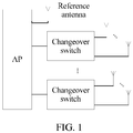
- the AP includes a relatively large quantity of antennas, as shown in FIG. 1 .
- the AP may include a reference antenna, a first antenna group, and a second antenna group.
- the AP may alternatively include more antenna groups.
- the first antenna group includes N antennas
- the second antenna group includes M antennas
- both M and N are integers greater than or equal to 1.
- a quantity of radio frequency circuits in the AP is less than a total quantity of antennas of the AP, and is greater than or equal to a quantity of antennas in any antenna group plus 1. To be specific, at a specific moment, only some antennas of the AP are used to collect signals by using the radio frequency circuit.
- the first antenna group and the second antenna group each may form an antenna array, or may jointly form an antenna array.
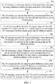
- FIG. 2 is a schematic flowchart of an angle of arrival estimation method according to an embodiment of this application. As shown in the figure, the method may include the following steps.
- Step 201 An AP collects, in a first time interval, a first signal from a terminal by using a reference antenna and each antenna in a first antenna group.
- Step 202 The AP collects, in a second time interval, a second signal from the terminal by using the reference antenna and each antenna in a second antenna group.
- Signals collected by a relatively large quantity of antennas are obtained by using a relatively small quantity of radio frequency circuits in the AP, and therefore the AP cannot collect signals by simultaneously using all antennas, and the signals are collected by the reference antenna, the first antenna group, and the second antenna group by using a method similar to time division multiplexing.
- Signals sent by the terminal to the AP are consecutive in time domain.
- Information such as phases and amplitudes of the signals that are consecutive in time domain are different at different times. Therefore, a part of the consecutive signals that is transmitted to the AP in the first time interval is referred to as the first signal, and a part of the consecutive signals that is transmitted to the AP in the second time interval is referred to as the second signal.
- Step 203 The AP estimates first CSI of the first signal.
- the first CSI includes N+1 vectors, and the N+1 vectors respectively correspond to N antennas in the first antenna group and the reference antenna.
- the first CSI may include four vectors that are separately CSI_1(1), CSI_1(2), CSI_1(3), and CSI_1(4), where CSI_1(1), CSI_1(2), and CSI_1(3) respectively correspond to the three antennas in the first antenna group, and CSI_1(4) corresponds to the reference antenna.
- Step 204 The AP estimates second CSI of the second signal.
- the second CSI includes M+1 vectors, and the M+1 vectors respectively correspond to M antennas in the second antenna group and the reference antenna.
- the second CSI may include five vectors that are separately CSI_2(1), CSI_2(2), CSI_2(3), CSI_2(4), and CSI_2(5), where CSI_2(1), CSI_2(2), CSI_2(3), and CSI_2(4) respectively correspond to the four antennas in the second antenna group, and CSI_2(5) corresponds to the reference antenna.
- the CSI may represent information about a phase and an amplitude of a signal received by each antenna at different frequencies.
- the AP may further estimate an angle of arrival of the terminal based on the estimated CSI.
- the CSI includes a vector corresponding to an antenna that collects a signal, each vector includes a plurality of elements, and each element represents a phase of the received signal at a frequency corresponding to the element.
- a quantity of elements included in each vector may be different values in different scenarios based on a protocol.
- a sequence of step 201 to step 204 is not limited in this embodiment of this application.
- the AP may estimate the first CSI and the second CSI after obtaining the first signal and the second signal; or may estimate the first CSI immediately after obtaining the first signal, and estimate the second CSI immediately after obtaining the second signal, in other words, step 201 and step 203 are combined, and step 202 and step 204 are combined.
- Step 205 The AP determines a phase difference vector between the first signal and the second signal based on a vector corresponding to the reference antenna in the first CSI and a vector corresponding to the reference antenna in the second CSI.
- the first signal and the second signal are signals that are sent by the terminal and that are transmitted to the AP in different time periods. Because sampling start times and front-end processing latencies are different when signals are received, phases of the received signals are also different.
- the reference antenna collects the first signal in the first time interval, and the vector corresponding to the reference antenna in the first CSI can reflect a phase formed when the first signal arrives at the reference antenna.
- the reference antenna further collects the second signal in the second time interval, and the vector corresponding to the reference antenna in the second CSI can reflect a phase formed when the second signal arrives at the reference antenna. Therefore, the phase difference vector between the first signal and the second signal can be determined by using the vector corresponding to the reference antenna in the first CSI and the vector corresponding to the reference antenna in the second CSI.
- a difference vector between the foregoing two phase vectors is used as the phase difference vector between the first signal and the second signal, to be specific, [ ⁇ 1 - ⁇ 1, ⁇ 2 - ⁇ 2, ..., ⁇ k - ⁇ k].
- the signal may be interfered with by noise in a receiving and sending process and a path transmission process.
- the AP may fit a plurality of elements included in the difference vector, and determine a phase difference at each frequency location in the phase difference vector.
- Step 206 The AP compensates for, by using the phase difference vector, each of the M vectors in the second CSI that are corresponding to the M antennas in the second antenna group. Because a sequence of the first time interval and the second time interval may be reversed, compensating for the second CSI by using the phase difference vector may be compensating for CSI corresponding to a signal that is collected first, or may be compensating for CSI corresponding to a signal that is collected last.
- CSI_2(2) [d 1 , d 2 , ..., d k ], ...
- CSI_2(M) [e 1 , e 2 , ..., e k ]
- FIG. 3 before compensation, two fold lines are respectively drawn based on a vector corresponding to an antenna in the first antenna group and a vector corresponding to an antenna in the second antenna group. After the vectors corresponding to the antennas in the second antenna group are compensated for, fold lines that are drawn based on compensated vectors are shown in FIG. 3 .
- the AP may further estimate, based on the first CSI and M compensated vectors in the second CSI, an angle of arrival of a signal sent by the terminal.
- Step 207 The AP estimates, based on the first CSI and M compensated vectors in the second CSI, an angle of arrival of a signal sent by the terminal.
- a linear array antenna is used as an example. As shown in FIG. 4 , it may be considered that incoming wave directions of signals received by antennas are parallel to each other, and therefore it may be considered that phases formed when signals are transmitted to a point A (that is, a location of an antenna 1), a point B, and a point C are the same.
- CSI corresponding to each antenna can reflect a phase of a signal received by the antenna, to be specific, a phase of a signal when the signal is transmitted to a location of an antenna 2 and a phase of a signal when the signal is transmitted to a location of an antenna 3 are known.
- a distance d1 between the antenna 1 and the antenna 2 and a distance d2 between the antenna 2 and the antenna 3 are also known.
- the AP may estimate an angle of arrival ⁇ 1 based on a wavelength of the signal. Further, if the first antenna group and the second antenna group form a two-dimensional antenna array, the angle of arrival estimated by the AP may include angles of different planes, in other words, a direction of the signal in three-dimensional space may be obtained.
- the N vectors in the first CSI that are corresponding to the N antennas in the first antenna group may also be compensated for by using the phase difference vector.
- the AP estimates, based on the second CSI and N compensated vectors in the first CSI, the angle of arrival of the signal sent by the terminal.
- the AP may send the estimated angle of arrival to a server.
- the server locates the terminal based on angles of arrival estimated by at least two APs.
- the AP may locate the terminal.
- the AP may receive a first message sent by the terminal, and send a second message to the terminal after receiving the first message, to respond to the first message.
- the AP may receive a third message sent by the terminal.
- the first message or the third message includes a time at which the terminal sends the first message
- the third message includes a time at which the terminal receives the second message.
- the AP may estimate a distance between the AP and the terminal based on the time at which the terminal sends the first message, a time at which the AP receives the first message, a time at which the AP sends the second message, and the time at which the terminal receives the second message.
- a frame structure of the third message sent by the terminal may include a category (category) field, a public action (public action) field, a dialog token (dialog token) field, a follow-up dialog token (follow up dialog token) field, a sending time (TOD) field, a receiving time (TOA) field, a sending time error (TOD error) field, a receiving time error (TOA error) field, and the like.
- the time at which the terminal sends the first message and the time at which the terminal receives the second message may be respectively added to the TOD field and the TOA field, and sent to the AP.
- the terminal sends the first message (FTM_2 (0, 0) in FIG. 6 ) to the AP at a moment T1
- the AP receives the first message at a moment T2
- the terminal receives the second message at a moment T4.
- the terminal then sends the third message (FTM_3 in FIG. 6 ) to the AP, and the message includes indication information of the moment T1 and the moment T4.
- a total transmission time of the first message and the second message is (T4-T1)-(T3-T2), and the distance between the AP and the terminal is v ⁇ [(T4-T1)-(T3-T2)]/2, where v represents a signal propagation speed.
- the distance between the AP and the terminal may be estimated based on a transmission time T2-T1 of the first message or a transmission time T4-T3 of the second message.
- the foregoing process may be triggered by the AP.
- the AP may send, to the terminal, indication information (for example, a fine timing measurement (fine timing measurement, FTM) request (request) shown in FIG. 6 ) used to trigger a ranging procedure, and the terminal replies with response information (ack), to indicate whether the terminal permits initiation of the ranging procedure. If the terminal permits initiation of the ranging procedure, the terminal sends the first message to the AP.
- indication information for example, a fine timing measurement (fine timing measurement, FTM) request (request) shown in FIG. 6
- ack response information
- the AP may alternatively locate the terminal based on a height of the AP, an estimated angle of arrival (which, as described above, may include an angle in a horizontal direction and an angle in a vertical direction), and an empirical value of a height at which a user holds the terminal.
- signals sent by the terminal may arrive at the AP through a plurality of transmission paths. Therefore, a signal received by the AP is superimposition of a plurality of signals that successively arrive at the AP through the plurality of paths.
- An angle of arrival of a signal on a line of sight (line of sight, LOS) path is an angle of arrival that needs to be used to locate the terminal. Therefore, the AP may further determine the signal on the LOS path in a plurality of signals that are from a same terminal and that arrive at the AP through different paths.
- the AP may perform a related operation on the received signal by using a frequency domain sequence on a known legacy long training field (legacy long training field, L-LTF). Because a legacy long training field (legacy long training field, L-LTF) in a packet is characterized by good autocorrelation, a plurality of pulse signals are obtained after the related operation.
- L-LTF legacy long training field
- the signal on the LOS path arrives at the AP first. Therefore, the AP may use, as the signal on the LOS path, a signal corresponding to a pulse signal that arrives at the AP first, and estimate an angle of arrival of the signal on the LOS path by using the foregoing angle of arrival estimation method, to locate the terminal.
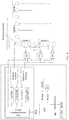
- an AP structure may further include a communications chip that works at 5 GHz or 2.4 GHz, a central processing unit (CPU), a flash memory (flash), a double rate (DDR) memory, a radio frequency front-end module that works at 5 GHz, a radio frequency front-end module that works at 2.4 GHz, a diplexer (diplexer), a changeover switch S2, a changeover switch S3, a changeover switch S4, a reference antenna, an antenna group 1, an antenna group 2, an antenna group 3, and an antenna group 4.
- a communications chip that works at 5 GHz or 2.4 GHz
- CPU central processing unit
- flash flash
- DDR double rate
- a radio frequency front-end module that works at 5 GHz
- radio frequency front-end module that works at 2.4 GHz
- diplexer diplexer
- changeover switch S2 a changeover switch S3, a changeover switch S4
- a reference antenna an antenna group 1, an antenna group 2, an antenna group 3, and an antenna group 4.
- the reference antenna is connected to one radio frequency front-end module.
- Three antennas in the antenna group 1 are respectively connected to a channel 1 of the changeover switch S2, a channel 1 of the changeover switch S3, and a channel 1 of the changeover switch S4.
- Three antennas in the antenna group 2 are respectively connected to a channel 2 of the changeover switch S2, a channel 2 of the changeover switch S3, and a channel 2 of the changeover switch S4.
- Three antennas in the antenna group 3 are respectively connected to a channel 3 of the changeover switch S2, a channel 3 of the changeover switch S3, and a channel 3 of the changeover switch S4.
- Three antennas in the antenna group 4 are respectively connected to a channel 4 of the changeover switch S2, a channel 4 of the changeover switch S3, and a channel 4 of the changeover switch S4.
- Each of the changeover switch S2, the changeover switch S3, and the changeover switch S4 connects, at a same moment, one of four antennas connected to each of the changeover switch S2, the changeover switch S3, and the changeover switch S4 to one radio frequency front-end module, to collect a signal.
- the AP structure shown in FIG. 8 is a specific embodiment obtained after detailing the AP structure shown in FIG. 1 . In actual application, the AP may include more or fewer elements than those shown in FIG. 8 .
- the changeover switches are disposed, so that signals received by the reference antenna and the three antennas in the antenna group 1 are collected in a time interval 1, and CSI_1 is obtained based on the received signals; signals received by the reference antenna and the three antennas in the antenna group 2 are collected in a time interval 2, and CSI_2 is obtained based on the received signals; signals received by the reference antenna and the three antennas in the antenna group 3 are collected in a time interval 3, and CSI_3 is obtained based on the received signals; and signals received by the reference antenna and the three antennas in the antenna group 4 are collected in a time interval 4, and CSI_4 is obtained based on the received signals.
- the AP determines, based on vectors corresponding to the reference antenna in CSI_1 and CSI_2, a phase difference vector between the signal collected by the reference antenna in the time interval 1 and the signal collected by the reference antenna in the time interval 2, and compensates for, by using the phase difference vector, vectors in CSI_2 that are corresponding to the antennas in the antenna group 2; determines, based on vectors corresponding to the reference antenna in CSI_1 and CSI_3, a phase difference vector between the signal collected by the reference antenna in the time interval 1 and the signal collected by the reference antenna in the time interval 3, and compensates for, by using the phase difference vector, vectors in CSI_3 that are corresponding to the antennas in the antenna group 3; and determines, based on vectors corresponding to the reference antenna in CSI_1 and CSI_4, a phase difference vector between the signal collected by the reference antenna in the time interval 1 and the signal collected by the reference antenna in the time interval 4, and compensates for, by using the phase difference vector, vectors in CSI
- Each changeover switch may control switching of a connected antenna through general purpose input/output (general purpose input output, GPIO) in the chip.
- general purpose input/output general purpose input output, GPIO
- a signal of each antenna is collected every 250 ms, so that a general positioning accuracy requirement on a terminal can be met. Therefore, for the foregoing AP that includes the four antenna groups, the changeover switch may be switched every 80 ms.
- the foregoing values are only examples. In actual application, different switching periods may be set based on different scenarios and different accuracy requirements. This is not limited in this embodiment of this application.
- the foregoing angle of arrival estimation method may be applied to a device in which a quantity of antennas is greater than a quantity of radio frequency circuits, and a changeover switch may be added to a hardware circuit, so that the radio frequency circuit collects, in different time periods, signals received by different antennas.
- the first device determines the phase difference vector between the first signal and the second signal based on the vector corresponding to the reference antenna in the first CSI and the vector corresponding to the reference antenna in the second CSI, and the phase difference is generated due to a difference between receiving times of signals sent by the second device.
- the first device compensates for, based on the phase difference vector, a vector other than the vector corresponding to the reference antenna in the second CSI (or the first CSI), which is equivalent to obtaining CSI that is obtained based on signals received by the reference antenna, the first antenna group, and the second antenna group in a same time period, and then estimating, based on the CSI, the angle of arrival of the signal sent by the second device. Because the angle of arrival of the second device is estimated by using the signals received by the reference antenna, the first antenna group, and the second antenna group, estimation accuracy of the angle of arrival is improved, and the quantity of radio frequency circuits does not need to be increased.
- an embodiment of this application further provides an angle of arrival estimation device, configured to implement the foregoing method embodiment.
- the device may be implemented by a wireless device. As shown in FIG. 9 , the device may include a receiving unit 901 and a processing unit 902, and may further include a sending unit 903.
- the receiving unit 901 is configured to: collect, in a first time interval, a first signal from a second device by using a reference antenna of the wireless device and each antenna in a first antenna group of the wireless device, where the first antenna group includes N antennas, and N is an integer greater than or equal to 1; and collect, in a second time interval, a second signal from the second device by using the reference antenna and each antenna in a second antenna group of the wireless device, where the second antenna group includes M antennas, and M is an integer greater than or equal to 1.
- the processing unit 902 is configured to: estimate first channel state information CSI, where the first CSI is CSI of the first signal, the first CSI includes N+1 vectors, and the N+1 vectors respectively correspond to the N antennas and the reference antenna; estimate second CSI, where the second CSI is CSI of the second signal, the second CSI includes M+1 vectors, and the M+1 vectors respectively correspond to the M antennas and the reference antenna; determine a phase difference vector between the first signal and the second signal based on a vector corresponding to the reference antenna in the first CSI and a vector corresponding to the reference antenna in the second CSI; and compensate for each of the M vectors corresponding to the M antennas in the second CSI by using the phase difference vector, and estimate, based on the first CSI and M compensated vectors in the second CSI, an angle of arrival of a signal sent by the second device, or compensate for each of the N vectors corresponding to the N antennas in the first CSI by using the phase difference vector, and estimate, based on the second CSI and
- the processing unit 902 when determining the phase difference vector between the first signal and the second signal that are collected by the reference antenna, is specifically configured to: calculate a difference between the vector corresponding to the reference antenna in the first CSI and the vector corresponding to the reference antenna in the second CSI, fit a plurality of elements in the difference based on frequencies corresponding to the plurality of elements in the difference, and determine a phase difference at each frequency location in the phase difference vector.
- the receiving unit 901 is further configured to receive a first message sent by the second device.
- the device further includes the sending unit 903, configured to send a second message to the second device, where the second message is a response to the first message.
- the receiving unit 901 is further configured to receive a third message sent by the second device.
- the first message or the third message includes a time at which the second device sends the first message, and the third message includes a time at which the second device receives the second message.
- the processing unit 902 is further configured to: estimate a distance between the device and the second device based on the time at which the second device sends the first message, a time at which the device receives the first message, a time at which the device sends the second message, and the time at which the second device receives the second message; and locate the second device based on the distance and the angle of arrival.
- the receiving unit and the sending unit may be separately disposed, or may form a transceiver unit.
- the transceiver unit may be integrated into the processing unit or may be implemented separately.
- These units may all be implemented in a form of software invoked by using a processing element, or may all be implemented in a form of hardware; or some units may be implemented in a form of software invoked by using a processing element, and some units may be implemented in a form of hardware.
- the processing element herein may be an integrated circuit having a signal processing capability.
- steps in the foregoing method or the foregoing units may be implemented by using a hardware integrated logic circuit in the processing element, or by using instructions in a form of software.
- These units may be one or more integrated circuits configured to implement the foregoing method, for example, one or more application-specific integrated circuits (ASIC), one or more microprocessors, or one or more field programmable gate arrays (FPGA).
- ASIC application-specific integrated circuits
- FPGA field programmable gate arrays
- the processing element may be a general purpose processor, for example, a central processing unit (CPU) or another processor that can invoke the program.
- these units may be integrated together and implemented in a form of a system-on-a-chip (SOC).
- SOC system-on-a-chip
- a wireless device 1000 may include a transceiver 1001 and a processor 1002.
- the transceiver 1001 includes a reference antenna, a first antenna group, and a second antenna group, the first antenna group includes N antennas, N is an integer greater than or equal to 1, the second antenna group includes M antennas, and M is an integer greater than or equal to 1.
- the transceiver 1001 is configured to: collect, in a first time interval, a first signal from a second device by using the reference antenna and each antenna in the first antenna group; and collect, in a second time interval, a second signal from the second device by using the reference antenna and each antenna in the second antenna group.
- the processor 1002 is configured to: estimate first channel state information CSI, where the first CSI is CSI of the first signal, the first CSI includes N+1 vectors, and the N+1 vectors respectively correspond to the N antennas and the reference antenna; estimate second CSI, where the second CSI is CSI of the second signal, the second CSI includes M+1 vectors, and the M+1 vectors respectively correspond to the M antennas and the reference antenna; determine a phase difference vector between the first signal and the second signal based on a vector corresponding to the reference antenna in the first CSI and a vector corresponding to the reference antenna in the second CSI; and compensate for each of the M vectors corresponding to the M antennas in the second CSI by using the phase difference vector, and estimate, based on the first CSI and M compensated vectors in the second CSI, an angle of arrival of a signal sent by the second device, or compensate for each of the N vectors corresponding to the N antennas in the first CSI by using the phase difference vector, and estimate, based on the second CSI and N
- the processor 1002 when determining the phase difference vector between the first signal and the second signal that are collected by the reference antenna, is specifically configured to: calculate a difference between the vector corresponding to the reference antenna in the first CSI and the vector corresponding to the reference antenna in the second CSI, fit a plurality of elements in the difference based on frequencies corresponding to the plurality of elements in the difference, and determine a phase difference at each frequency location in the phase difference vector.
- the transceiver 1001 is further configured to: receive a first message sent by the second device, and send a second message to the second device, where the second message is a response to the first message; and receive a third message sent by the second device, where the first message or the third message includes a time at which the second device sends the first message, and the third message includes a time at which the second device receives the second message.
- the processor 1002 is further configured to: estimate a distance between the wireless device and the second device based on the time at which the second device sends the first message, a time at which the wireless device receives the first message, a time at which the wireless device sends the second message, and the time at which the second device receives the second message; and locate the second device based on the distance and the angle of arrival.
- the processor 1002 may be a general purpose CPU, a microprocessor, an ASIC, or one or more integrated circuits configured to control program execution in the solutions of this application.
- the processor 1002 may include one or more CPUs.
- the device may include a plurality of processors.
- processors may be a single-core processor, or may be a multi-core processor.
- the processor herein may be one or more devices, a circuit, and/or a processing core used for processing data (such as a computer program instruction).
- this application provides a computer readable storage medium.
- the computer readable storage medium stores a computer instruction, and when the instruction runs on a computer, the computer performs the angle of arrival estimation method in the foregoing method embodiment.
- this application may be provided as a method, a system, or a computer program product. Therefore, this application may use a form of hardware only embodiments, software only embodiments, or embodiments with a combination of software and hardware. Moreover, the present invention may use a form of a computer program product that is implemented on one or more computer-readable storage media (including but not limited to a disk memory, an optical memory, and the like) that include a computer instruction.
- a computer-readable storage media including but not limited to a disk memory, an optical memory, and the like
Landscapes
- Engineering & Computer Science (AREA)
- Physics & Mathematics (AREA)
- General Physics & Mathematics (AREA)
- Radar, Positioning & Navigation (AREA)
- Remote Sensing (AREA)
- Computer Networks & Wireless Communication (AREA)
- Signal Processing (AREA)
- Quality & Reliability (AREA)
- Mobile Radio Communication Systems (AREA)
Description
- This application relates to the wireless communications field, and in particular, to an angle of arrival estimation method and device.
- A method for determining the direction of arrival of a radio signal is known from
US 2016/0187451 A1 . An access point (access point, AP) in a wireless local area network (wireless local area network, WLAN) may estimate, by using an antenna array technology, an angle of arrival (angle of arrival, AoA) at which a radio signal of a terminal device arrives at the AP. The AoA may be used to locate the terminal device. - The AP collects, by using a radio frequency circuit, a radio signal received by an antenna. Generally, one radio frequency circuit can obtain, at a same moment, only a radio signal collected by one antenna. A hardware circuit of one AP includes a limited quantity of radio frequency circuits, for example, there are usually three or four radio frequency circuits. However, an increase of a quantity of antennas in an antenna array helps improve estimation accuracy of an angle of arrival of a terminal. If the quantity of radio frequency circuits is increased to improve the estimation accuracy of the angle of arrival of the terminal, design complexity, costs, and the like of a hardware circuit are increased.
- The invention provides an angle of arrival estimation method and an angle of arrival estimation device as recited in the
independent claims - Advantageous embodiments are set out in the dependent claims. Aspects of the invention which contribute to the understanding of the invention are listed below. While several embodiments and/or examples have been disclosed in the description, the subject matter for which protection is sought is strictly and solely limited to those embodiments and/or examples encompassed by the scope of the appended claims. Embodiments and/or examples mentioned in the description that do not fall under the scope of the claims are useful for understanding the invention.
- This application provides an angle of arrival estimation method and device, to ensure estimation accuracy of an angle of arrival by using a plurality of antennas without increasing a quantity of radio frequency circuits.
- According to a first aspect, this application provides an angle of arrival estimation method, including:
- collecting, by a first device in a first time interval, a first signal from a second device by using a reference antenna of the first device and each antenna in a first antenna group, where the first antenna group includes N antennas, and N is an integer greater than or equal to 1; collecting, in a second time interval, a second signal from the second device by using the reference antenna and each antenna in a second antenna group of the first device, where the second antenna group includes M antennas, and M is an integer greater than or equal to 1;
- estimating, by the first device, first channel state information (channel state information, CSI), where the first CSI is CSI of the first signal, the first CSI includes N+1 vectors, and the N+1 vectors respectively correspond to the N antennas and the reference antenna; estimating, by the first device, second CSI, where the second CSI is CSI of the second signal, the second CSI includes M+1 vectors, and the M+1 vectors respectively correspond to the M antennas and the reference antenna;
- determining, by the first device, a phase difference vector between the first signal and the second signal based on a vector corresponding to the reference antenna in the first CSI and a vector corresponding to the reference antenna in the second CSI; and compensating for a sampling time offset of signals sent by the second device and a processing latency difference of a radio frequency front end, by the first device, each of the M vectors corresponding to the M
- antennas in the second CSI by using the phase difference vector, and estimating, based on the first CSI and M compensated vectors in the second CSI, an angle of arrival of a signal sent by the second device; or compensating for, by the first device, each of the N vectors corresponding to the N antennas in the first CSI by using the phase difference vector, and estimating, based on the second CSI and N compensated vectors in the first CSI, an angle of arrival of a signal sent by the second device ; characterized in that each vector of the N+1 vectors and of the M+1 vectors includes a plurality of elements, wherein each element represents a phase of a received signal at a frequency corresponding to the element.
- The foregoing method may be applied to a device in which a quantity of antennas is greater than a quantity of radio frequency circuits, so that the radio frequency circuit collects, in different time periods, signals received by different antennas. According to the foregoing method, the first device determines the phase difference vector between the first signal and the second signal based on the vector corresponding to the reference antenna in the first CSI and the vector corresponding to the reference antenna in the second CSI, and the phase difference is generated due to a sampling time offset of signals sent by the second device and a processing latency difference of a radio frequency front end. The first device compensates for, based on the phase difference vector, a vector other than the vector corresponding to the reference antenna in the second CSI (or the first CSI), which is equivalent to obtaining CSI that is obtained based on signals received by the reference antenna, the first antenna group, and the second antenna group in a same time period, and then estimating, based on the CSI, the angle of arrival of the signal sent by the second device. Because the angle of arrival of the second device is estimated by using the signals received by the reference antenna, the first antenna group, and the second antenna group, estimation accuracy of the angle of arrival is improved, and the quantity of radio frequency circuits does not need to be increased.
- In a possible implementation, when determining the phase difference vector between the first signal and the second signal that are collected by the reference antenna, the first device may calculate a difference between the vector corresponding to the reference antenna in the first CSI and the vector corresponding to the reference antenna in the second CSI, fit a plurality of elements in the difference based on frequencies corresponding to the plurality of elements in the difference, and determine a phase difference at each frequency location in the phase difference vector.
- Because a fitting operation helps reduce noise interference, the estimation accuracy of the angle of arrival is further improved by using the foregoing implementation.
- In a possible implementation, the first device receives a first message sent by the second device, and sends a second message to the second device, where the second message is a response to the first message. The first device receives a third message sent by the second device, where the first message or the third message includes a time at which the second device sends the first message, and the third message includes a time at which the second device receives the second message. The first device estimates a distance between the first device and the second device based on the time at which the second device sends the first message, a time at which the first device receives the first message, a time at which the first device sends the second message, and the time at which the second device receives the second message, and locates the second device based on the estimated distance and the estimated angle of arrival.
- In a conventional angle of arrival-based locating method, usually, angles of arrival of signals sent by a same terminal are sent by a plurality of APs at known locations to a server, and the server locates the terminal. In the foregoing method, the first device may estimate the distance between the first device and the second device based on a transmission time of the first message and a transmission time of the second message, and can then locate the second device with reference to the estimated angle of arrival of the signal sent by the second device, and does not need to locate the second device with reference to angles of arrival estimated by a plurality of devices.
- According to a second aspect, this application provides an angle of arrival estimation device, where the device may include a receiving unit and a processing unit, and may further include a sending unit, and is configured to implement the method according to any one of the implementations of the first aspect.
-
-
FIG. 1 is a first schematic structural diagram of an AP according to an embodiment of this application; -
FIG. 2 is a schematic flowchart of an angle of arrival estimation method according to an embodiment of this application; -
FIG. 3 is a schematic diagram of a vector before compensation and a compensated vector according to an embodiment of this application; -
FIG. 4 is a schematic diagram showing that an angle of arrival is estimated by using a linear array antenna according to an embodiment of this application; -
FIG. 5 is a schematic diagram of a frame structure of a second message according to an embodiment of this application; -
FIG. 6 is a schematic diagram of a ranging procedure according to an embodiment of this application; -
FIG. 7 is a schematic diagram of multipath transmission according to an embodiment of this application; -
FIG. 8 is a second schematic structural diagram of an AP according to an embodiment of this application; -
FIG. 9 is a first schematic structural diagram of an angle of arrival estimation device according to an embodiment of this application; and -
FIG. 10 is a second schematic structural diagram of an angle of arrival estimation device according to an embodiment of this application. - To make the objectives, technical solutions, and advantages of this application clearer, the following further describes this application in detail with reference to the accompanying drawings.
- With the development of intelligent terminals, more applications can provide personalized and differentiated services for users based on location information of the terminal, such as advertisement push, nearby service discovery, and navigation. Positioning accuracy of the terminal affects user experience of these services.
- An AOA-based locating method is a common method for locating a terminal. When the terminal is located by using the method, a larger quantity of receive antennas helps improve estimation accuracy of an angle of arrival of the terminal, thereby helping improve positioning accuracy of the terminal. However, if a radio frequency circuit is configured for each antenna, design complexity, costs, and the like of a hardware circuit are increased.
- Therefore, the embodiments of this application provide an angle of arrival estimation method, to estimate an angle of arrival by using a relatively large quantity of antennas without increasing a quantity of radio frequency circuits.
- The angle of arrival estimation method provided in the embodiments of this application may be applied to a wireless local area network (wireless local area network, WLAN), or may be applied to a Long Term Evolution (Long Term Evolution, LTE) system, a 5th Generation mobile communications (the 5th generation, 5G) system, or another wireless communications system. The method may be used by a first device to estimate an angle of arrival of a signal sent by a second device, to locate the second device. For example, the method may be applied to a scenario in which an AP locates a terminal, a terminal locates an AP, a base station locates a terminal, a terminal locates a base station, a terminal locates a terminal, or the like. The terminal in the embodiments of this application may include various handheld devices, in-vehicle devices, wearable devices (wearable device), computing devices, or the like that have a wireless function. It should be understood that words such as "first" and "second" in the embodiments of this application are only used for distinctive description, but cannot be understood as indication or implication of relative importance, and cannot be understood as an indication or implication of a sequence. For example, a first time interval and a second time interval are used to distinguish between different time periods, but do not indicate a sequence of the two time intervals. For another example, a first antenna group and a second antenna group are used to distinguish between two groups of antennas, but do not indicate a difference between importance of the two groups of antennas.
- A scenario in which an AP locates a terminal in a WLAN is used as an example below to describe in detail the angle of arrival estimation method provided in the embodiments of this application.
- To meet a positioning accuracy requirement for the terminal, the AP includes a relatively large quantity of antennas, as shown in
FIG. 1 . Specifically, the AP may include a reference antenna, a first antenna group, and a second antenna group. The AP may alternatively include more antenna groups. The first antenna group includes N antennas, the second antenna group includes M antennas, and both M and N are integers greater than or equal to 1. A quantity of radio frequency circuits in the AP is less than a total quantity of antennas of the AP, and is greater than or equal to a quantity of antennas in any antenna group plus 1. To be specific, at a specific moment, only some antennas of the AP are used to collect signals by using the radio frequency circuit. - The first antenna group and the second antenna group each may form an antenna array, or may jointly form an antenna array.
-
FIG. 2 is a schematic flowchart of an angle of arrival estimation method according to an embodiment of this application. As shown in the figure, the method may include the following steps. - Step 201: An AP collects, in a first time interval, a first signal from a terminal by using a reference antenna and each antenna in a first antenna group.
- Step 202: The AP collects, in a second time interval, a second signal from the terminal by using the reference antenna and each antenna in a second antenna group.
- Signals collected by a relatively large quantity of antennas are obtained by using a relatively small quantity of radio frequency circuits in the AP, and therefore the AP cannot collect signals by simultaneously using all antennas, and the signals are collected by the reference antenna, the first antenna group, and the second antenna group by using a method similar to time division multiplexing.
- Signals sent by the terminal to the AP are consecutive in time domain. Information such as phases and amplitudes of the signals that are consecutive in time domain are different at different times. Therefore, a part of the consecutive signals that is transmitted to the AP in the first time interval is referred to as the first signal, and a part of the consecutive signals that is transmitted to the AP in the second time interval is referred to as the second signal.
- Step 203: The AP estimates first CSI of the first signal. The first CSI includes N+1 vectors, and the N+1 vectors respectively correspond to N antennas in the first antenna group and the reference antenna.
- For example, if the first antenna group includes three antennas, the first CSI may include four vectors that are separately CSI_1(1), CSI_1(2), CSI_1(3), and CSI_1(4), where CSI_1(1), CSI_1(2), and CSI_1(3) respectively correspond to the three antennas in the first antenna group, and CSI_1(4) corresponds to the reference antenna.
- Step 204: The AP estimates second CSI of the second signal. The second CSI includes M+1 vectors, and the M+1 vectors respectively correspond to M antennas in the second antenna group and the reference antenna.
- For example, if the second antenna group includes four antennas, the second CSI may include five vectors that are separately CSI_2(1), CSI_2(2), CSI_2(3), CSI_2(4), and CSI_2(5), where CSI_2(1), CSI_2(2), CSI_2(3), and CSI_2(4) respectively correspond to the four antennas in the second antenna group, and CSI_2(5) corresponds to the reference antenna.
- The CSI may represent information about a phase and an amplitude of a signal received by each antenna at different frequencies. The AP may further estimate an angle of arrival of the terminal based on the estimated CSI. The CSI includes a vector corresponding to an antenna that collects a signal, each vector includes a plurality of elements, and each element represents a phase of the received signal at a frequency corresponding to the element. A quantity of elements included in each vector may be different values in different scenarios based on a protocol.
- A sequence of
step 201 to step 204 is not limited in this embodiment of this application. The AP may estimate the first CSI and the second CSI after obtaining the first signal and the second signal; or may estimate the first CSI immediately after obtaining the first signal, and estimate the second CSI immediately after obtaining the second signal, in other words, step 201 and step 203 are combined, and step 202 and step 204 are combined. - Step 205: The AP determines a phase difference vector between the first signal and the second signal based on a vector corresponding to the reference antenna in the first CSI and a vector corresponding to the reference antenna in the second CSI.
- As described above, the first signal and the second signal are signals that are sent by the terminal and that are transmitted to the AP in different time periods. Because sampling start times and front-end processing latencies are different when signals are received, phases of the received signals are also different. The reference antenna collects the first signal in the first time interval, and the vector corresponding to the reference antenna in the first CSI can reflect a phase formed when the first signal arrives at the reference antenna. The reference antenna further collects the second signal in the second time interval, and the vector corresponding to the reference antenna in the second CSI can reflect a phase formed when the second signal arrives at the reference antenna. Therefore, the phase difference vector between the first signal and the second signal can be determined by using the vector corresponding to the reference antenna in the first CSI and the vector corresponding to the reference antenna in the second CSI.
- For example, if the vector corresponding to the reference antenna in the first CSI is CSI_1(4)=[a1 · ejα1, a2 · ejα2, ..., ak · ejαk], a corresponding phase vector is [α1, α2, ..., αk]; and if the vector corresponding to the reference antenna in the second CSI is CSI_2(5)=[b1 · ejβ1, b2 · ejβ2, ..., bk · ejβk], a corresponding phase vector is [β1, β2,..., βk], where k is a sequence number of a frequency. In this case, a difference vector between the foregoing two phase vectors is used as the phase difference vector between the first signal and the second signal, to be specific, [α1 - β1, α2 - β2, ..., αk - βk].
- However, the signal may be interfered with by noise in a receiving and sending process and a path transmission process. To reduce impact of noise interference, in a possible implementation, after calculating the difference vector between the foregoing two vectors, the AP may fit a plurality of elements included in the difference vector, and determine a phase difference at each frequency location in the phase difference vector.
- A frequency difference between adjacent frequencies is fixed, and phase differences at frequency locations are generally linear. Therefore, linear fitting may be performed on the elements in the difference vector, to obtain a linear offset function of the phase, and then the phase difference at each frequency location in the phase difference vector is determined based on the linear offset function. For example, fitting may be performed by using a
degree 1 polynomial y=px+q, and a coefficient of thedegree 1 polynomial may be solved by using an algorithm such as the least square method. This is not limited in this embodiment of this application. After the linear offset function y=px+q is determined, the phase difference at each frequency location is determined based on the function, to obtain the phase difference vector. - Step 206: The AP compensates for, by using the phase difference vector, each of the M vectors in the second CSI that are corresponding to the M antennas in the second antenna group. Because a sequence of the first time interval and the second time interval may be reversed, compensating for the second CSI by using the phase difference vector may be compensating for CSI corresponding to a signal that is collected first, or may be compensating for CSI corresponding to a signal that is collected last.
- For example, if the phase difference vector determined in
step 205 is θ=[θ1, θ2, ..., θk], and the M vectors in the second CSI that are corresponding to the M antennas in the second antenna group are respectively CSI_2(1)=[c1, c2, ..., ck], CSI_2(2)=[d1, d2, ..., dk], ..., and CSI_2(M)=[e1, e2, ..., ek], M compensated vectors may be CSI'_2(1)= [c1 · ejθ1, c2 · ejθ2, ... ck · ejθk], CSI'_2(2)=[d1 · ejθ1 , d2 · ejθ2 , ... dk · ejθk ], ..., and CSI'_2(M)=[e1 · ejθ1 , e2 · ejθ2 , ... ek · ejθk ]. As shown inFIG. 3 , before compensation, two fold lines are respectively drawn based on a vector corresponding to an antenna in the first antenna group and a vector corresponding to an antenna in the second antenna group. After the vectors corresponding to the antennas in the second antenna group are compensated for, fold lines that are drawn based on compensated vectors are shown inFIG. 3 . - After the AP compensates for the M vectors in the second CSI, which is equivalent to obtaining CSI that is obtained based on signals received by the reference antenna, the first antenna group, and the second antenna group in the first time interval, the AP may further estimate, based on the first CSI and M compensated vectors in the second CSI, an angle of arrival of a signal sent by the terminal.
- Step 207: The AP estimates, based on the first CSI and M compensated vectors in the second CSI, an angle of arrival of a signal sent by the terminal.
- A linear array antenna is used as an example. As shown in
FIG. 4 , it may be considered that incoming wave directions of signals received by antennas are parallel to each other, and therefore it may be considered that phases formed when signals are transmitted to a point A (that is, a location of an antenna 1), a point B, and a point C are the same. CSI corresponding to each antenna can reflect a phase of a signal received by the antenna, to be specific, a phase of a signal when the signal is transmitted to a location of anantenna 2 and a phase of a signal when the signal is transmitted to a location of anantenna 3 are known. In addition, a distance d1 between theantenna 1 and theantenna 2 and a distance d2 between theantenna 2 and theantenna 3 are also known. Therefore, the AP may estimate an angle of arrival ϕ1 based on a wavelength of the signal. Further, if the first antenna group and the second antenna group form a two-dimensional antenna array, the angle of arrival estimated by the AP may include angles of different planes, in other words, a direction of the signal in three-dimensional space may be obtained. - As described above, in
step 206, the N vectors in the first CSI that are corresponding to the N antennas in the first antenna group may also be compensated for by using the phase difference vector. Correspondingly, instep 207, the AP estimates, based on the second CSI and N compensated vectors in the first CSI, the angle of arrival of the signal sent by the terminal. - In a possible implementation, after estimating the angle of arrival of the signal sent by the terminal, the AP may send the estimated angle of arrival to a server. The server locates the terminal based on angles of arrival estimated by at least two APs.
- In another possible implementation, the AP may locate the terminal. The AP may receive a first message sent by the terminal, and send a second message to the terminal after receiving the first message, to respond to the first message. Then, the AP may receive a third message sent by the terminal. The first message or the third message includes a time at which the terminal sends the first message, and the third message includes a time at which the terminal receives the second message. The AP may estimate a distance between the AP and the terminal based on the time at which the terminal sends the first message, a time at which the AP receives the first message, a time at which the AP sends the second message, and the time at which the terminal receives the second message.
- For example, as shown in
FIG. 5 , a frame structure of the third message sent by the terminal may include a category (category) field, a public action (public action) field, a dialog token (dialog token) field, a follow-up dialog token (follow up dialog token) field, a sending time (TOD) field, a receiving time (TOA) field, a sending time error (TOD error) field, a receiving time error (TOA error) field, and the like. The time at which the terminal sends the first message and the time at which the terminal receives the second message may be respectively added to the TOD field and the TOA field, and sent to the AP. - For example, as shown in
FIG. 6 , the terminal sends the first message (FTM_2 (0, 0) inFIG. 6 ) to the AP at a moment T1, the AP receives the first message at a moment T2, and sends the second message (Ack inFIG. 6 ) to the terminal at a moment T3, and the terminal receives the second message at a moment T4. The terminal then sends the third message (FTM_3 inFIG. 6 ) to the AP, and the message includes indication information of the moment T1 and the moment T4. It can be learned that a total transmission time of the first message and the second message is (T4-T1)-(T3-T2), and the distance between the AP and the terminal is v×[(T4-T1)-(T3-T2)]/2, where v represents a signal propagation speed. According to the foregoing algorithm, even if time of the AP is inconsistent with time of the terminal, calculation of the transmission time is not affected. Certainly, if the time of the AP is consistent with the time of the terminal, the distance between the AP and the terminal may be estimated based on a transmission time T2-T1 of the first message or a transmission time T4-T3 of the second message. - Specifically, the foregoing process may be triggered by the AP. For example, the AP may send, to the terminal, indication information (for example, a fine timing measurement (fine timing measurement, FTM) request (request) shown in
FIG. 6 ) used to trigger a ranging procedure, and the terminal replies with response information (ack), to indicate whether the terminal permits initiation of the ranging procedure. If the terminal permits initiation of the ranging procedure, the terminal sends the first message to the AP. - When the AP locates the terminal, the AP may alternatively locate the terminal based on a height of the AP, an estimated angle of arrival (which, as described above, may include an angle in a horizontal direction and an angle in a vertical direction), and an empirical value of a height at which a user holds the terminal.
- In addition, as shown in
FIG. 7 , signals sent by the terminal may arrive at the AP through a plurality of transmission paths. Therefore, a signal received by the AP is superimposition of a plurality of signals that successively arrive at the AP through the plurality of paths. An angle of arrival of a signal on a line of sight (line of sight, LOS) path is an angle of arrival that needs to be used to locate the terminal. Therefore, the AP may further determine the signal on the LOS path in a plurality of signals that are from a same terminal and that arrive at the AP through different paths. - In a possible implementation, the AP may perform a related operation on the received signal by using a frequency domain sequence on a known legacy long training field (legacy long training field, L-LTF). Because a legacy long training field (legacy long training field, L-LTF) in a packet is characterized by good autocorrelation, a plurality of pulse signals are obtained after the related operation. Usually, the signal on the LOS path arrives at the AP first. Therefore, the AP may use, as the signal on the LOS path, a signal corresponding to a pulse signal that arrives at the AP first, and estimate an angle of arrival of the signal on the LOS path by using the foregoing angle of arrival estimation method, to locate the terminal.
- The foregoing embodiment of this application is described by using an example in which the AP includes the reference antenna and two antenna groups. It should be understood that the AP may alternatively include more antenna groups. For example, as shown in
FIG. 8 , an AP structure may further include a communications chip that works at 5 GHz or 2.4 GHz, a central processing unit (CPU), a flash memory (flash), a double rate (DDR) memory, a radio frequency front-end module that works at 5 GHz, a radio frequency front-end module that works at 2.4 GHz, a diplexer (diplexer), a changeover switch S2, a changeover switch S3, a changeover switch S4, a reference antenna, anantenna group 1, anantenna group 2, anantenna group 3, and anantenna group 4. The reference antenna is connected to one radio frequency front-end module. Three antennas in theantenna group 1 are respectively connected to achannel 1 of the changeover switch S2, achannel 1 of the changeover switch S3, and achannel 1 of the changeover switch S4. Three antennas in theantenna group 2 are respectively connected to achannel 2 of the changeover switch S2, achannel 2 of the changeover switch S3, and achannel 2 of the changeover switch S4. Three antennas in theantenna group 3 are respectively connected to achannel 3 of the changeover switch S2, achannel 3 of the changeover switch S3, and achannel 3 of the changeover switch S4. Three antennas in theantenna group 4 are respectively connected to achannel 4 of the changeover switch S2, achannel 4 of the changeover switch S3, and achannel 4 of the changeover switch S4. Each of the changeover switch S2, the changeover switch S3, and the changeover switch S4 connects, at a same moment, one of four antennas connected to each of the changeover switch S2, the changeover switch S3, and the changeover switch S4 to one radio frequency front-end module, to collect a signal. It should be understood that the AP structure shown inFIG. 8 is a specific embodiment obtained after detailing the AP structure shown inFIG. 1 . In actual application, the AP may include more or fewer elements than those shown inFIG. 8 . The changeover switches are disposed, so that signals received by the reference antenna and the three antennas in theantenna group 1 are collected in atime interval 1, and CSI_1 is obtained based on the received signals; signals received by the reference antenna and the three antennas in theantenna group 2 are collected in atime interval 2, and CSI_2 is obtained based on the received signals; signals received by the reference antenna and the three antennas in theantenna group 3 are collected in atime interval 3, and CSI_3 is obtained based on the received signals; and signals received by the reference antenna and the three antennas in theantenna group 4 are collected in atime interval 4, and CSI_4 is obtained based on the received signals. Then, the AP determines, based on vectors corresponding to the reference antenna in CSI_1 and CSI_2, a phase difference vector between the signal collected by the reference antenna in thetime interval 1 and the signal collected by the reference antenna in thetime interval 2, and compensates for, by using the phase difference vector, vectors in CSI_2 that are corresponding to the antennas in theantenna group 2; determines, based on vectors corresponding to the reference antenna in CSI_1 and CSI_3, a phase difference vector between the signal collected by the reference antenna in thetime interval 1 and the signal collected by the reference antenna in thetime interval 3, and compensates for, by using the phase difference vector, vectors in CSI_3 that are corresponding to the antennas in theantenna group 3; and determines, based on vectors corresponding to the reference antenna in CSI_1 and CSI_4, a phase difference vector between the signal collected by the reference antenna in thetime interval 1 and the signal collected by the reference antenna in thetime interval 4, and compensates for, by using the phase difference vector, vectors in CSI_4 that are corresponding to the antennas in theantenna group 4. Finally, the angle of arrival of the signal sent by the terminal is estimated based on CSI_1 and the foregoing compensated vectors. Each changeover switch may control switching of a connected antenna through general purpose input/output (general purpose input output, GPIO) in the chip. In consideration of a moving speed of the terminal, usually, a signal of each antenna is collected every 250 ms, so that a general positioning accuracy requirement on a terminal can be met. Therefore, for the foregoing AP that includes the four antenna groups, the changeover switch may be switched every 80 ms. Certainly, the foregoing values are only examples. In actual application, different switching periods may be set based on different scenarios and different accuracy requirements. This is not limited in this embodiment of this application. - The foregoing angle of arrival estimation method may be applied to a device in which a quantity of antennas is greater than a quantity of radio frequency circuits, and a changeover switch may be added to a hardware circuit, so that the radio frequency circuit collects, in different time periods, signals received by different antennas. In the foregoing method, the first device determines the phase difference vector between the first signal and the second signal based on the vector corresponding to the reference antenna in the first CSI and the vector corresponding to the reference antenna in the second CSI, and the phase difference is generated due to a difference between receiving times of signals sent by the second device. The first device compensates for, based on the phase difference vector, a vector other than the vector corresponding to the reference antenna in the second CSI (or the first CSI), which is equivalent to obtaining CSI that is obtained based on signals received by the reference antenna, the first antenna group, and the second antenna group in a same time period, and then estimating, based on the CSI, the angle of arrival of the signal sent by the second device. Because the angle of arrival of the second device is estimated by using the signals received by the reference antenna, the first antenna group, and the second antenna group, estimation accuracy of the angle of arrival is improved, and the quantity of radio frequency circuits does not need to be increased.
- Based on a same technical concept, an embodiment of this application further provides an angle of arrival estimation device, configured to implement the foregoing method embodiment. The device may be implemented by a wireless device. As shown in
FIG. 9 , the device may include a receivingunit 901 and aprocessing unit 902, and may further include a sendingunit 903. - The receiving
unit 901 is configured to: collect, in a first time interval, a first signal from a second device by using a reference antenna of the wireless device and each antenna in a first antenna group of the wireless device, where the first antenna group includes N antennas, and N is an integer greater than or equal to 1; and collect, in a second time interval, a second signal from the second device by using the reference antenna and each antenna in a second antenna group of the wireless device, where the second antenna group includes M antennas, and M is an integer greater than or equal to 1. - The
processing unit 902 is configured to: estimate first channel state information CSI, where the first CSI is CSI of the first signal, the first CSI includes N+1 vectors, and the N+1 vectors respectively correspond to the N antennas and the reference antenna; estimate second CSI, where the second CSI is CSI of the second signal, the second CSI includes M+1 vectors, and the M+1 vectors respectively correspond to the M antennas and the reference antenna; determine a phase difference vector between the first signal and the second signal based on a vector corresponding to the reference antenna in the first CSI and a vector corresponding to the reference antenna in the second CSI; and compensate for each of the M vectors corresponding to the M antennas in the second CSI by using the phase difference vector, and estimate, based on the first CSI and M compensated vectors in the second CSI, an angle of arrival of a signal sent by the second device, or compensate for each of the N vectors corresponding to the N antennas in the first CSI by using the phase difference vector, and estimate, based on the second CSI and N compensated vectors in the first CSI, an angle of arrival of a signal sent by the second device. - In a possible implementation, when determining the phase difference vector between the first signal and the second signal that are collected by the reference antenna, the
processing unit 902 is specifically configured to: calculate a difference between the vector corresponding to the reference antenna in the first CSI and the vector corresponding to the reference antenna in the second CSI, fit a plurality of elements in the difference based on frequencies corresponding to the plurality of elements in the difference, and determine a phase difference at each frequency location in the phase difference vector. - In a possible implementation, the receiving
unit 901 is further configured to receive a first message sent by the second device. - The device further includes the sending
unit 903, configured to send a second message to the second device, where the second message is a response to the first message. - The receiving
unit 901 is further configured to receive a third message sent by the second device. The first message or the third message includes a time at which the second device sends the first message, and the third message includes a time at which the second device receives the second message. - The
processing unit 902 is further configured to: estimate a distance between the device and the second device based on the time at which the second device sends the first message, a time at which the device receives the first message, a time at which the device sends the second message, and the time at which the second device receives the second message; and locate the second device based on the distance and the angle of arrival. - It should be noted that division of the foregoing units is merely division of logical functions. For example, the receiving unit and the sending unit may be separately disposed, or may form a transceiver unit. In addition, the transceiver unit may be integrated into the processing unit or may be implemented separately. These units may all be implemented in a form of software invoked by using a processing element, or may all be implemented in a form of hardware; or some units may be implemented in a form of software invoked by using a processing element, and some units may be implemented in a form of hardware. The processing element herein may be an integrated circuit having a signal processing capability. In an implementation process, steps in the foregoing method or the foregoing units may be implemented by using a hardware integrated logic circuit in the processing element, or by using instructions in a form of software. These units may be one or more integrated circuits configured to implement the foregoing method, for example, one or more application-specific integrated circuits (ASIC), one or more microprocessors, or one or more field programmable gate arrays (FPGA). For another example, when a unit is implemented in a form of a program invoked by using a processing element, the processing element may be a general purpose processor, for example, a central processing unit (CPU) or another processor that can invoke the program. For another example, these units may be integrated together and implemented in a form of a system-on-a-chip (SOC).
- Based on a same technical concept, an embodiment of this application further provides a wireless device, configured to implement the foregoing method embodiment. As shown in
FIG. 10 , awireless device 1000 may include atransceiver 1001 and aprocessor 1002. Thetransceiver 1001 includes a reference antenna, a first antenna group, and a second antenna group, the first antenna group includes N antennas, N is an integer greater than or equal to 1, the second antenna group includes M antennas, and M is an integer greater than or equal to 1. - The
transceiver 1001 is configured to: collect, in a first time interval, a first signal from a second device by using the reference antenna and each antenna in the first antenna group; and collect, in a second time interval, a second signal from the second device by using the reference antenna and each antenna in the second antenna group. - The
processor 1002 is configured to: estimate first channel state information CSI, where the first CSI is CSI of the first signal, the first CSI includes N+1 vectors, and the N+1 vectors respectively correspond to the N antennas and the reference antenna; estimate second CSI, where the second CSI is CSI of the second signal, the second CSI includes M+1 vectors, and the M+1 vectors respectively correspond to the M antennas and the reference antenna; determine a phase difference vector between the first signal and the second signal based on a vector corresponding to the reference antenna in the first CSI and a vector corresponding to the reference antenna in the second CSI; and compensate for each of the M vectors corresponding to the M antennas in the second CSI by using the phase difference vector, and estimate, based on the first CSI and M compensated vectors in the second CSI, an angle of arrival of a signal sent by the second device, or compensate for each of the N vectors corresponding to the N antennas in the first CSI by using the phase difference vector, and estimate, based on the second CSI and N compensated vectors in the first CSI, an angle of arrival of a signal sent by the second device. - In a possible implementation, when determining the phase difference vector between the first signal and the second signal that are collected by the reference antenna, the
processor 1002 is specifically configured to: calculate a difference between the vector corresponding to the reference antenna in the first CSI and the vector corresponding to the reference antenna in the second CSI, fit a plurality of elements in the difference based on frequencies corresponding to the plurality of elements in the difference, and determine a phase difference at each frequency location in the phase difference vector. - In a possible implementation, the
transceiver 1001 is further configured to: receive a first message sent by the second device, and send a second message to the second device, where the second message is a response to the first message; and receive a third message sent by the second device, where the first message or the third message includes a time at which the second device sends the first message, and the third message includes a time at which the second device receives the second message. - The
processor 1002 is further configured to: estimate a distance between the wireless device and the second device based on the time at which the second device sends the first message, a time at which the wireless device receives the first message, a time at which the wireless device sends the second message, and the time at which the second device receives the second message; and locate the second device based on the distance and the angle of arrival. - The
processor 1002 may be a general purpose CPU, a microprocessor, an ASIC, or one or more integrated circuits configured to control program execution in the solutions of this application. In specific implementation, in an embodiment, theprocessor 1002 may include one or more CPUs. - In specific implementation, in an embodiment, the device may include a plurality of processors. Each of these processors may be a single-core processor, or may be a multi-core processor. The processor herein may be one or more devices, a circuit, and/or a processing core used for processing data (such as a computer program instruction).
- Based on a same technical concept, this application provides a computer readable storage medium. The computer readable storage medium stores a computer instruction, and when the instruction runs on a computer, the computer performs the angle of arrival estimation method in the foregoing method embodiment.
- A person skilled in the art should understand that the embodiments of this application may be provided as a method, a system, or a computer program product. Therefore, this application may use a form of hardware only embodiments, software only embodiments, or embodiments with a combination of software and hardware. Moreover, the present invention may use a form of a computer program product that is implemented on one or more computer-readable storage media (including but not limited to a disk memory, an optical memory, and the like) that include a computer instruction.
- The objectives, technical methods, and beneficial effects of this application have been described in detail in the foregoing embodiments. It should be understood that the foregoing description is merely specific implementations of this application, but are not intended to limit the protection scope of this application. Any modifications and variations made on the basis of the technical solutions of this application shall fall within the protection scope of this application.
Claims (6)
- An angle of arrival estimation method, comprising:collecting (201), by a first device in a first time interval, a first signal from a second device by using a reference antenna of the first device and each antenna in a first antenna group of the first device, wherein the first antenna group comprises N antennas, and N is an integer greater than or equal to 1;collecting (202), by the first device in a second time interval, a second signal from the second device by using the reference antenna and each antenna in a second antenna group of the first device, wherein the second antenna group comprises M antennas, and M is an integer greater than or equal to 1;estimating (203), by the first device, first channel state information, CSI, wherein the first CSI is CSI of the first signal, the first CSI comprises N+1 vectors, and the N+1 vectors respectively correspond to the N antennas and the reference antenna ;estimating (204), by the first device, second CSI, wherein the second CSI is CSI of the second signal, the second CSI comprises M+1 vectors, and the M+1 vectors respectively correspond to the M antennas and the reference antenna;determining (205), by the first device, a phase difference vector between the first signal and the second signal based on a vector corresponding to the reference antenna in the first CSI and a vector corresponding to the reference antenna in the second CSI; andcompensating (206) for a sampling time offset of signals sent by the second device and a processing latency difference of a radio frequency front end, by the first device, each of the M vectors corresponding to the M antennas in the second CSI by using the phase difference vector, and estimating (207), based on the first CSI and M compensated vectors in the second CSI, an angle of arrival of a signal sent by the second device ; characterized in that each vector of the N+1 vectors and of the M+1 vectors includes a plurality of elements, wherein each element represents a phase of a received signal at a frequency corresponding to the element.
- The method according to claim 1, wherein the determining a phase difference vector between the first signal and the second signal comprises:calculating, by the first device, a difference between the vector corresponding to the reference antenna in the first CSI and the vector corresponding to the reference antenna in the second CSI; andfitting, by the first device, a plurality of elements in the difference based on frequencies corresponding to the plurality of elements in the difference, and determining a phase difference at each frequency location in the phase difference vector.
- The method according to claim 1 or 2, further comprising:receiving, by the first device, a first message sent by the second device, and sending a second message to the second device, wherein the second message is a response to the first message;receiving, by the first device, a third message sent by the second device, wherein the first message or the third message comprises a time at which the second device sends the first message, and the third message comprises a time at which the second device receives the second message;estimating, by the first device, a distance between the first device and the second device based on the time at which the second device sends the first message, a time at which the first device receives the first message, a time at which the first device sends the second message, and the time at which the second device receives the second message; andlocating, by the first device, the second device based on the distance and the angle of arrival.
- An angle of arrival estimation device, comprising:a receiving unit (901), configured to: collect, in a first time interval, a first signal from a wireless device (1000) by using a reference antenna of another wireless device (1000) and each antenna in a first antenna group of the another wireless device (1000), wherein the first antenna group comprises N antennas, and N is an integer greater than or equal to 1; and collect, in a second time interval, a second signal from the wireless device (1000) by using the reference antenna and each antenna in a second antenna group of the another wireless device (1000), wherein the second antenna group comprises M antennas, and M is an integer greater than or equal to 1; anda processing unit (902), configured to: estimate first channel state information, CSI, wherein the first CSI is CSI of the first signal, the first CSI comprises N+1 vectors, and the N+1 vectors respectively correspond to the N antennas and the reference antenna ; estimate second CSI, wherein the second CSI is CSI of the second signal, the second CSI comprises M+1 vectors, and the M+1 vectors respectively correspond to the M antennas and the reference antenna ; determine a phase difference vector between the first signal and the second signal based on a vector corresponding to the reference antenna in the first CSI and a vector corresponding to the reference antenna in the second CSI; and compensate for a sampling time offset of signals sent by the wireless device (1000) and a processing latency difference of a radio frequency front end, each of the M vectors corresponding to the M antennas in the second CSI by using the phase difference vector, and estimate, based on the first CSI and M compensated vectors in the second CSI, an angle of arrival of a signal sent by the wireless device (1000) ; characterized in that each vector of the N+1 vectors and of the M+1 vectors includes a plurality of elements, wherein each element represents a phase of a received signal at a frequency corresponding to the element.
- The device according to claim 4, wherein when determining the phase difference vector between the first signal and the second signal that are collected by the reference antenna, the processing unit (902) is specifically configured to:calculate a difference between the vector corresponding to the reference antenna in the first CSI and the vector corresponding to the reference antenna in the second CSI; andfit a plurality of elements in the difference based on frequencies corresponding to the plurality of elements in the difference, and determine a phase difference at each frequency location in the phase difference vector.
- The device according to claim 4 or 5, wherein the receiving unit (901) is further configured to receive a first message sent by the wireless device (1000);the device further comprises a sending unit (903), configured to send a second message to the wireless device (1000), wherein the second message is a response to the first message;the receiving unit (901) is further configured to receive a third message sent by the wireless device (1000), wherein the first message or the third message comprises a time at which the wireless device (1000) sends the first message, and the third message comprises a time at which the wireless device (1000) receives the second message; andthe processing unit (902) is further configured to: estimate a distance between the device and the another wireless device (1000) based on the time at which the wireless device (1000) sends the first message, a time at which the receiving unit (901) receives the first message, a time at which the sending unit (903) sends the second message, and the time at which the wireless device (1000) receives the second message; and locate the wireless device (1000) based on the distance and the angle of arrival.
Applications Claiming Priority (1)
| Application Number | Priority Date | Filing Date | Title |
|---|---|---|---|
| CN201810967452.5A CN110857973B (en) | 2018-08-23 | 2018-08-23 | Arrival angle estimation method and device |
Publications (2)
| Publication Number | Publication Date |
|---|---|
| EP3614165A1 EP3614165A1 (en) | 2020-02-26 |
| EP3614165B1 true EP3614165B1 (en) | 2021-12-15 |
Family
ID=67742195
Family Applications (1)
| Application Number | Title | Priority Date | Filing Date |
|---|---|---|---|
| EP19193257.3A Active EP3614165B1 (en) | 2018-08-23 | 2019-08-23 | Angle of arrival estimation method and device |
Country Status (3)
| Country | Link |
|---|---|
| US (1) | US10917870B2 (en) |
| EP (1) | EP3614165B1 (en) |
| CN (1) | CN110857973B (en) |
Families Citing this family (22)
| Publication number | Priority date | Publication date | Assignee | Title |
|---|---|---|---|---|
| DE102019200661A1 (en) * | 2018-08-30 | 2020-03-05 | Deckel Maho Pfronten Gmbh | MACHINE TOOL FOR MACHINING A WORKPIECE |
| US11768266B2 (en) * | 2020-03-31 | 2023-09-26 | WiTagg, Inc. | System and method for estimating the angle of arrival using antenna arrays |
| KR20210155946A (en) | 2020-06-17 | 2021-12-24 | 삼성전자주식회사 | Electronic device for performing positioning and method thereof |
| CN115997430B (en) * | 2020-08-25 | 2024-12-17 | 上海诺基亚贝尔股份有限公司 | Relative phase determination for frequency drift compensation |
| US11656314B2 (en) | 2020-09-28 | 2023-05-23 | Shenzhen GOODIX Technology Co., Ltd. | AoA/AoD calculation with mirror disambiguation |
| US20220099783A1 (en) * | 2020-09-28 | 2022-03-31 | Shenzhen GOODIX Technology Co., Ltd. | AoA/AoD CALCULATION WITH LOW ANGLE OF INCIDENCE |
| CN112202462B (en) * | 2020-10-15 | 2022-02-15 | Oppo广东移动通信有限公司 | Time delay compensation method and device, electronic equipment and storage medium |
| CN114545322A (en) * | 2020-11-26 | 2022-05-27 | Oppo广东移动通信有限公司 | Method, device and equipment for determining angle of arrival (AOA) and storage medium |
| CN112684406B (en) * | 2020-12-18 | 2024-05-14 | Oppo广东移动通信有限公司 | Methods for determining angle of arrival and related products |
| EP4057028B1 (en) * | 2021-03-09 | 2024-05-15 | Huawei Technologies Co., Ltd. | Time measurement method and apparatus |
| CN115061084B (en) * | 2021-03-09 | 2025-06-24 | 华为技术有限公司 | Time measurement method and device |
| CN113655435B (en) * | 2021-07-22 | 2024-05-07 | 深圳云里物里科技股份有限公司 | Method, device, signal receiving equipment, system and medium for determining arrival angle |
| CN113613170A (en) * | 2021-08-16 | 2021-11-05 | 苏州云享阁智能科技有限公司 | High-precision indoor positioning system and method based on low-cost antenna extension |
| CN117941277A (en) * | 2021-08-31 | 2024-04-26 | 上海诺基亚贝尔股份有限公司 | Phase compensation for channel state information |
| CN114755558B (en) * | 2022-04-08 | 2024-06-21 | 广东利扬芯片测试股份有限公司 | Data compensation method of radio frequency chip |
| CN117129939A (en) * | 2022-05-20 | 2023-11-28 | 华为技术有限公司 | Arrival angle measuring method, electronic equipment and storage medium |
| CN114966542A (en) * | 2022-07-29 | 2022-08-30 | 合肥有感科技有限责任公司 | Digital key positioning system and positioning method |
| CN117835145A (en) * | 2022-09-28 | 2024-04-05 | 中兴通讯股份有限公司 | Method and device for estimating arrival angle of channel sounding reference signal SRS |
| CN118042590A (en) | 2022-11-02 | 2024-05-14 | 锐捷网络股份有限公司 | A communication method, a communication device, a storage medium and an electronic device |
| CN116017275A (en) * | 2022-12-15 | 2023-04-25 | 芯原微电子(上海)股份有限公司 | Bluetooth positioning method, terminal equipment, electronic equipment and storage medium |
| CN118283810A (en) * | 2022-12-29 | 2024-07-02 | 华为技术有限公司 | Communication method and device |
| WO2024138571A1 (en) * | 2022-12-29 | 2024-07-04 | 成都市联洲国际技术有限公司 | Client position determination method and apparatus, and processor |
Family Cites Families (12)
| Publication number | Priority date | Publication date | Assignee | Title |
|---|---|---|---|---|
| US5936575A (en) * | 1998-02-13 | 1999-08-10 | Science And Applied Technology, Inc. | Apparatus and method for determining angles-of-arrival and polarization of incoming RF signals |
| US10187133B2 (en) * | 2004-04-02 | 2019-01-22 | Rearden, Llc | System and method for power control and antenna grouping in a distributed-input-distributed-output (DIDO) network |
| JP2006242761A (en) * | 2005-03-03 | 2006-09-14 | Mitsubishi Electric Corp | Radio arrival direction measuring device |
| CN102947722B (en) | 2010-06-19 | 2015-10-21 | 诺基亚公司 | For estimating the method and apparatus of arrival direction |
| WO2014160052A1 (en) * | 2013-03-14 | 2014-10-02 | Microchip Technology Incorporated | System and method for determining an angle of arrival in a wireless network |
| US9823330B2 (en) | 2013-05-03 | 2017-11-21 | Cisco Technology, Inc. | Angle of arrival location sensing with antenna array |
| IL227858A (en) * | 2013-08-08 | 2015-06-30 | Elbit System Bmd And Land Ew Elisra Ltd | System and method for directionally classifying radio signals |
| US9445237B1 (en) | 2015-03-11 | 2016-09-13 | Qualcomm Incorporated | First arrival path based multipath mitigation for angle of arrival estimation |
| CN107037422A (en) * | 2017-05-11 | 2017-08-11 | 西北大学 | A kind of passive type localization method towards multiple application |
| US10476539B1 (en) * | 2017-09-15 | 2019-11-12 | Marvell International Ltd. | Automatic gain control adjustment in multi-antenna short-range wireless system |
| US10346657B1 (en) * | 2018-01-10 | 2019-07-09 | Abl Ip Holding Llc | RFID system with antenna integrated in a luminaire |
| CN108387864B (en) * | 2018-03-02 | 2021-09-24 | 北京邮电大学 | A method and device for calculating angle of arrival |
-
2018
- 2018-08-23 CN CN201810967452.5A patent/CN110857973B/en active Active
-
2019
- 2019-08-21 US US16/547,290 patent/US10917870B2/en active Active
- 2019-08-23 EP EP19193257.3A patent/EP3614165B1/en active Active
Non-Patent Citations (1)
| Title |
|---|
| None * |
Also Published As
| Publication number | Publication date |
|---|---|
| US10917870B2 (en) | 2021-02-09 |
| CN110857973A (en) | 2020-03-03 |
| EP3614165A1 (en) | 2020-02-26 |
| CN110857973B (en) | 2021-11-26 |
| US20200068523A1 (en) | 2020-02-27 |
Similar Documents
| Publication | Publication Date | Title |
|---|---|---|
| US10917870B2 (en) | Angle of arrival estimation method and device | |
| CN115604843A (en) | Transmission method, device, communication device and storage medium | |
| CN118233920A (en) | Sensing method, sensing device, communication equipment and storage medium | |
| CN117203914A (en) | Signal processing methods, devices, equipment and storage media | |
| US20250081020A1 (en) | Sensing mode switching method and apparatus, and communication device | |
| US20250097754A1 (en) | Sensing manner switching method and apparatus, communication device, and storage medium | |
| US20260031916A1 (en) | Sensing method and apparatus | |
| CN118233021A (en) | Sensing method, sensing device and communication equipment | |
| WO2023207509A1 (en) | Positioning method and apparatus for use in sidelink, and readable storage medium | |
| JP7818719B2 (en) | Positioning information determination method, positioning method and related device | |
| WO2024140841A1 (en) | Sensing methods and apparatuses | |
| WO2024114460A1 (en) | Measurement method and apparatus, and device | |
| WO2016163923A1 (en) | Enhanced time of arrival positioning system | |
| CN113376572B (en) | Network positioning method, device, electronic equipment and storage medium | |
| WO2020119777A1 (en) | Wireless signal processing method and device, terminal and storage medium | |
| CN117354710A (en) | Carrier phase correlation measurement method, device, equipment and readable storage medium | |
| CN113259834B (en) | Positioning method, WLAN device and storage medium | |
| WO2024255234A1 (en) | Wireless sensing method and apparatus for environment depth and computer readable storage medium | |
| CN119729758A (en) | Non-stationary time domain positioning using frequency hopping | |
| WO2024131689A1 (en) | Sensing method, sensing apparatus, and communication device | |
| CN120677780A (en) | Communication method and communication device | |
| CN119111103A (en) | Measuring method and measuring device | |
| CN119644251B (en) | Method and device for positioning radiation source, electronic equipment and storage medium | |
| US12452861B2 (en) | Positioning method and apparatus, WLAN device, and storage medium | |
| US20240306135A1 (en) | Communication method and communication apparatus |
Legal Events
| Date | Code | Title | Description |
|---|---|---|---|
| PUAI | Public reference made under article 153(3) epc to a published international application that has entered the european phase |
Free format text: ORIGINAL CODE: 0009012 |
|
| STAA | Information on the status of an ep patent application or granted ep patent |
Free format text: STATUS: THE APPLICATION HAS BEEN PUBLISHED |
|
| AK | Designated contracting states |
Kind code of ref document: A1 Designated state(s): AL AT BE BG CH CY CZ DE DK EE ES FI FR GB GR HR HU IE IS IT LI LT LU LV MC MK MT NL NO PL PT RO RS SE SI SK SM TR |
|
| AX | Request for extension of the european patent |
Extension state: BA ME |
|
| STAA | Information on the status of an ep patent application or granted ep patent |
Free format text: STATUS: REQUEST FOR EXAMINATION WAS MADE |
|
| 17P | Request for examination filed |
Effective date: 20200824 |
|
| RBV | Designated contracting states (corrected) |
Designated state(s): AL AT BE BG CH CY CZ DE DK EE ES FI FR GB GR HR HU IE IS IT LI LT LU LV MC MK MT NL NO PL PT RO RS SE SI SK SM TR |
|
| STAA | Information on the status of an ep patent application or granted ep patent |
Free format text: STATUS: EXAMINATION IS IN PROGRESS |
|
| 17Q | First examination report despatched |
Effective date: 20201013 |
|
| GRAP | Despatch of communication of intention to grant a patent |
Free format text: ORIGINAL CODE: EPIDOSNIGR1 |
|
| STAA | Information on the status of an ep patent application or granted ep patent |
Free format text: STATUS: GRANT OF PATENT IS INTENDED |
|
| INTG | Intention to grant announced |
Effective date: 20210702 |
|
| RAP3 | Party data changed (applicant data changed or rights of an application transferred) |
Owner name: HUAWEI TECHNOLOGIES CO., LTD. |
|
| RIN1 | Information on inventor provided before grant (corrected) |
Inventor name: PAN, CHUN Inventor name: HE, ZHIJIAN Inventor name: XU, YONGQIAN Inventor name: WANG, YUNGUI |
|
| GRAS | Grant fee paid |
Free format text: ORIGINAL CODE: EPIDOSNIGR3 |
|
| GRAA | (expected) grant |
Free format text: ORIGINAL CODE: 0009210 |
|
| STAA | Information on the status of an ep patent application or granted ep patent |
Free format text: STATUS: THE PATENT HAS BEEN GRANTED |
|
| AK | Designated contracting states |
Kind code of ref document: B1 Designated state(s): AL AT BE BG CH CY CZ DE DK EE ES FI FR GB GR HR HU IE IS IT LI LT LU LV MC MK MT NL NO PL PT RO RS SE SI SK SM TR |
|
| REG | Reference to a national code |
Ref country code: GB Ref legal event code: FG4D Ref country code: CH Ref legal event code: EP |
|
| REG | Reference to a national code |
Ref country code: IE Ref legal event code: FG4D Ref country code: DE Ref legal event code: R096 Ref document number: 602019010045 Country of ref document: DE |
|
| REG | Reference to a national code |
Ref country code: AT Ref legal event code: REF Ref document number: 1455893 Country of ref document: AT Kind code of ref document: T Effective date: 20220115 |
|
| REG | Reference to a national code |
Ref country code: LT Ref legal event code: MG9D |
|
| REG | Reference to a national code |
Ref country code: NL Ref legal event code: MP Effective date: 20211215 |
|
| PG25 | Lapsed in a contracting state [announced via postgrant information from national office to epo] |
Ref country code: RS Free format text: LAPSE BECAUSE OF FAILURE TO SUBMIT A TRANSLATION OF THE DESCRIPTION OR TO PAY THE FEE WITHIN THE PRESCRIBED TIME-LIMIT Effective date: 20211215 Ref country code: LT Free format text: LAPSE BECAUSE OF FAILURE TO SUBMIT A TRANSLATION OF THE DESCRIPTION OR TO PAY THE FEE WITHIN THE PRESCRIBED TIME-LIMIT Effective date: 20211215 Ref country code: FI Free format text: LAPSE BECAUSE OF FAILURE TO SUBMIT A TRANSLATION OF THE DESCRIPTION OR TO PAY THE FEE WITHIN THE PRESCRIBED TIME-LIMIT Effective date: 20211215 Ref country code: BG Free format text: LAPSE BECAUSE OF FAILURE TO SUBMIT A TRANSLATION OF THE DESCRIPTION OR TO PAY THE FEE WITHIN THE PRESCRIBED TIME-LIMIT Effective date: 20220315 |
|
| REG | Reference to a national code |
Ref country code: AT Ref legal event code: MK05 Ref document number: 1455893 Country of ref document: AT Kind code of ref document: T Effective date: 20211215 |
|
| PG25 | Lapsed in a contracting state [announced via postgrant information from national office to epo] |
Ref country code: SE Free format text: LAPSE BECAUSE OF FAILURE TO SUBMIT A TRANSLATION OF THE DESCRIPTION OR TO PAY THE FEE WITHIN THE PRESCRIBED TIME-LIMIT Effective date: 20211215 Ref country code: NO Free format text: LAPSE BECAUSE OF FAILURE TO SUBMIT A TRANSLATION OF THE DESCRIPTION OR TO PAY THE FEE WITHIN THE PRESCRIBED TIME-LIMIT Effective date: 20220315 Ref country code: LV Free format text: LAPSE BECAUSE OF FAILURE TO SUBMIT A TRANSLATION OF THE DESCRIPTION OR TO PAY THE FEE WITHIN THE PRESCRIBED TIME-LIMIT Effective date: 20211215 Ref country code: HR Free format text: LAPSE BECAUSE OF FAILURE TO SUBMIT A TRANSLATION OF THE DESCRIPTION OR TO PAY THE FEE WITHIN THE PRESCRIBED TIME-LIMIT Effective date: 20211215 Ref country code: GR Free format text: LAPSE BECAUSE OF FAILURE TO SUBMIT A TRANSLATION OF THE DESCRIPTION OR TO PAY THE FEE WITHIN THE PRESCRIBED TIME-LIMIT Effective date: 20220316 |
|
| PG25 | Lapsed in a contracting state [announced via postgrant information from national office to epo] |
Ref country code: NL Free format text: LAPSE BECAUSE OF FAILURE TO SUBMIT A TRANSLATION OF THE DESCRIPTION OR TO PAY THE FEE WITHIN THE PRESCRIBED TIME-LIMIT Effective date: 20211215 |
|
| PG25 | Lapsed in a contracting state [announced via postgrant information from national office to epo] |
Ref country code: SM Free format text: LAPSE BECAUSE OF FAILURE TO SUBMIT A TRANSLATION OF THE DESCRIPTION OR TO PAY THE FEE WITHIN THE PRESCRIBED TIME-LIMIT Effective date: 20211215 Ref country code: SK Free format text: LAPSE BECAUSE OF FAILURE TO SUBMIT A TRANSLATION OF THE DESCRIPTION OR TO PAY THE FEE WITHIN THE PRESCRIBED TIME-LIMIT Effective date: 20211215 Ref country code: RO Free format text: LAPSE BECAUSE OF FAILURE TO SUBMIT A TRANSLATION OF THE DESCRIPTION OR TO PAY THE FEE WITHIN THE PRESCRIBED TIME-LIMIT Effective date: 20211215 Ref country code: PT Free format text: LAPSE BECAUSE OF FAILURE TO SUBMIT A TRANSLATION OF THE DESCRIPTION OR TO PAY THE FEE WITHIN THE PRESCRIBED TIME-LIMIT Effective date: 20220418 Ref country code: ES Free format text: LAPSE BECAUSE OF FAILURE TO SUBMIT A TRANSLATION OF THE DESCRIPTION OR TO PAY THE FEE WITHIN THE PRESCRIBED TIME-LIMIT Effective date: 20211215 Ref country code: EE Free format text: LAPSE BECAUSE OF FAILURE TO SUBMIT A TRANSLATION OF THE DESCRIPTION OR TO PAY THE FEE WITHIN THE PRESCRIBED TIME-LIMIT Effective date: 20211215 Ref country code: CZ Free format text: LAPSE BECAUSE OF FAILURE TO SUBMIT A TRANSLATION OF THE DESCRIPTION OR TO PAY THE FEE WITHIN THE PRESCRIBED TIME-LIMIT Effective date: 20211215 |
|
| PG25 | Lapsed in a contracting state [announced via postgrant information from national office to epo] |
Ref country code: PL Free format text: LAPSE BECAUSE OF FAILURE TO SUBMIT A TRANSLATION OF THE DESCRIPTION OR TO PAY THE FEE WITHIN THE PRESCRIBED TIME-LIMIT Effective date: 20211215 Ref country code: AT Free format text: LAPSE BECAUSE OF FAILURE TO SUBMIT A TRANSLATION OF THE DESCRIPTION OR TO PAY THE FEE WITHIN THE PRESCRIBED TIME-LIMIT Effective date: 20211215 |
|
| REG | Reference to a national code |
Ref country code: DE Ref legal event code: R097 Ref document number: 602019010045 Country of ref document: DE |
|
| PG25 | Lapsed in a contracting state [announced via postgrant information from national office to epo] |
Ref country code: IS Free format text: LAPSE BECAUSE OF FAILURE TO SUBMIT A TRANSLATION OF THE DESCRIPTION OR TO PAY THE FEE WITHIN THE PRESCRIBED TIME-LIMIT Effective date: 20220415 |
|
| PLBE | No opposition filed within time limit |
Free format text: ORIGINAL CODE: 0009261 |
|
| STAA | Information on the status of an ep patent application or granted ep patent |
Free format text: STATUS: NO OPPOSITION FILED WITHIN TIME LIMIT |
|
| PG25 | Lapsed in a contracting state [announced via postgrant information from national office to epo] |
Ref country code: DK Free format text: LAPSE BECAUSE OF FAILURE TO SUBMIT A TRANSLATION OF THE DESCRIPTION OR TO PAY THE FEE WITHIN THE PRESCRIBED TIME-LIMIT Effective date: 20211215 Ref country code: AL Free format text: LAPSE BECAUSE OF FAILURE TO SUBMIT A TRANSLATION OF THE DESCRIPTION OR TO PAY THE FEE WITHIN THE PRESCRIBED TIME-LIMIT Effective date: 20211215 |
|
| 26N | No opposition filed |
Effective date: 20220916 |
|
| PG25 | Lapsed in a contracting state [announced via postgrant information from national office to epo] |
Ref country code: SI Free format text: LAPSE BECAUSE OF FAILURE TO SUBMIT A TRANSLATION OF THE DESCRIPTION OR TO PAY THE FEE WITHIN THE PRESCRIBED TIME-LIMIT Effective date: 20211215 |
|
| PG25 | Lapsed in a contracting state [announced via postgrant information from national office to epo] |
Ref country code: MC Free format text: LAPSE BECAUSE OF FAILURE TO SUBMIT A TRANSLATION OF THE DESCRIPTION OR TO PAY THE FEE WITHIN THE PRESCRIBED TIME-LIMIT Effective date: 20211215 |
|
| REG | Reference to a national code |
Ref country code: CH Ref legal event code: PL |
|
| PG25 | Lapsed in a contracting state [announced via postgrant information from national office to epo] |
Ref country code: LU Free format text: LAPSE BECAUSE OF NON-PAYMENT OF DUE FEES Effective date: 20220823 Ref country code: LI Free format text: LAPSE BECAUSE OF NON-PAYMENT OF DUE FEES Effective date: 20220831 Ref country code: CH Free format text: LAPSE BECAUSE OF NON-PAYMENT OF DUE FEES Effective date: 20220831 |
|
| REG | Reference to a national code |
Ref country code: BE Ref legal event code: MM Effective date: 20220831 |
|
| PG25 | Lapsed in a contracting state [announced via postgrant information from national office to epo] |
Ref country code: IT Free format text: LAPSE BECAUSE OF FAILURE TO SUBMIT A TRANSLATION OF THE DESCRIPTION OR TO PAY THE FEE WITHIN THE PRESCRIBED TIME-LIMIT Effective date: 20211215 |
|
| PG25 | Lapsed in a contracting state [announced via postgrant information from national office to epo] |
Ref country code: IE Free format text: LAPSE BECAUSE OF NON-PAYMENT OF DUE FEES Effective date: 20220823 Ref country code: FR Free format text: LAPSE BECAUSE OF NON-PAYMENT OF DUE FEES Effective date: 20220831 |
|
| PG25 | Lapsed in a contracting state [announced via postgrant information from national office to epo] |
Ref country code: BE Free format text: LAPSE BECAUSE OF NON-PAYMENT OF DUE FEES Effective date: 20220831 |
|
| PG25 | Lapsed in a contracting state [announced via postgrant information from national office to epo] |
Ref country code: HU Free format text: LAPSE BECAUSE OF FAILURE TO SUBMIT A TRANSLATION OF THE DESCRIPTION OR TO PAY THE FEE WITHIN THE PRESCRIBED TIME-LIMIT; INVALID AB INITIO Effective date: 20190823 |
|
| PG25 | Lapsed in a contracting state [announced via postgrant information from national office to epo] |
Ref country code: CY Free format text: LAPSE BECAUSE OF FAILURE TO SUBMIT A TRANSLATION OF THE DESCRIPTION OR TO PAY THE FEE WITHIN THE PRESCRIBED TIME-LIMIT Effective date: 20211215 |
|
| PG25 | Lapsed in a contracting state [announced via postgrant information from national office to epo] |
Ref country code: MK Free format text: LAPSE BECAUSE OF FAILURE TO SUBMIT A TRANSLATION OF THE DESCRIPTION OR TO PAY THE FEE WITHIN THE PRESCRIBED TIME-LIMIT Effective date: 20211215 |
|
| PG25 | Lapsed in a contracting state [announced via postgrant information from national office to epo] |
Ref country code: MT Free format text: LAPSE BECAUSE OF FAILURE TO SUBMIT A TRANSLATION OF THE DESCRIPTION OR TO PAY THE FEE WITHIN THE PRESCRIBED TIME-LIMIT Effective date: 20211215 |
|
| PGFP | Annual fee paid to national office [announced via postgrant information from national office to epo] |
Ref country code: DE Payment date: 20250702 Year of fee payment: 7 |
|
| PGFP | Annual fee paid to national office [announced via postgrant information from national office to epo] |
Ref country code: GB Payment date: 20250703 Year of fee payment: 7 |
|
| PG25 | Lapsed in a contracting state [announced via postgrant information from national office to epo] |
Ref country code: TR Free format text: LAPSE BECAUSE OF FAILURE TO SUBMIT A TRANSLATION OF THE DESCRIPTION OR TO PAY THE FEE WITHIN THE PRESCRIBED TIME-LIMIT Effective date: 20211215 |