EP3614139A1 - Liquid chromatograph, mobile phase supply device, liquid chromatograph analysis method and mobile phase supply method - Google Patents
Liquid chromatograph, mobile phase supply device, liquid chromatograph analysis method and mobile phase supply method Download PDFInfo
- Publication number
- EP3614139A1 EP3614139A1 EP19191160.1A EP19191160A EP3614139A1 EP 3614139 A1 EP3614139 A1 EP 3614139A1 EP 19191160 A EP19191160 A EP 19191160A EP 3614139 A1 EP3614139 A1 EP 3614139A1
- Authority
- EP
- European Patent Office
- Prior art keywords
- mobile phase
- pipe
- mixer
- storage
- aqueous solution
- Prior art date
- Legal status (The legal status is an assumption and is not a legal conclusion. Google has not performed a legal analysis and makes no representation as to the accuracy of the status listed.)
- Granted
Links
Images



Classifications
-
- G—PHYSICS
- G01—MEASURING; TESTING
- G01N—INVESTIGATING OR ANALYSING MATERIALS BY DETERMINING THEIR CHEMICAL OR PHYSICAL PROPERTIES
- G01N30/00—Investigating or analysing materials by separation into components using adsorption, absorption or similar phenomena or using ion-exchange, e.g. chromatography or field flow fractionation
- G01N30/02—Column chromatography
-
- G—PHYSICS
- G01—MEASURING; TESTING
- G01N—INVESTIGATING OR ANALYSING MATERIALS BY DETERMINING THEIR CHEMICAL OR PHYSICAL PROPERTIES
- G01N30/00—Investigating or analysing materials by separation into components using adsorption, absorption or similar phenomena or using ion-exchange, e.g. chromatography or field flow fractionation
- G01N30/02—Column chromatography
- G01N30/26—Conditioning of the fluid carrier; Flow patterns
- G01N30/28—Control of physical parameters of the fluid carrier
- G01N30/34—Control of physical parameters of the fluid carrier of fluid composition, e.g. gradient
-
- B—PERFORMING OPERATIONS; TRANSPORTING
- B01—PHYSICAL OR CHEMICAL PROCESSES OR APPARATUS IN GENERAL
- B01D—SEPARATION
- B01D15/00—Separating processes involving the treatment of liquids with solid sorbents; Apparatus therefor
- B01D15/08—Selective adsorption, e.g. chromatography
- B01D15/10—Selective adsorption, e.g. chromatography characterised by constructional or operational features
-
- G—PHYSICS
- G01—MEASURING; TESTING
- G01N—INVESTIGATING OR ANALYSING MATERIALS BY DETERMINING THEIR CHEMICAL OR PHYSICAL PROPERTIES
- G01N30/00—Investigating or analysing materials by separation into components using adsorption, absorption or similar phenomena or using ion-exchange, e.g. chromatography or field flow fractionation
- G01N30/02—Column chromatography
- G01N30/04—Preparation or injection of sample to be analysed
-
- G—PHYSICS
- G01—MEASURING; TESTING
- G01N—INVESTIGATING OR ANALYSING MATERIALS BY DETERMINING THEIR CHEMICAL OR PHYSICAL PROPERTIES
- G01N30/00—Investigating or analysing materials by separation into components using adsorption, absorption or similar phenomena or using ion-exchange, e.g. chromatography or field flow fractionation
- G01N30/02—Column chromatography
- G01N30/04—Preparation or injection of sample to be analysed
- G01N30/16—Injection
- G01N30/20—Injection using a sampling valve
-
- G—PHYSICS
- G01—MEASURING; TESTING
- G01N—INVESTIGATING OR ANALYSING MATERIALS BY DETERMINING THEIR CHEMICAL OR PHYSICAL PROPERTIES
- G01N30/00—Investigating or analysing materials by separation into components using adsorption, absorption or similar phenomena or using ion-exchange, e.g. chromatography or field flow fractionation
- G01N30/02—Column chromatography
- G01N30/26—Conditioning of the fluid carrier; Flow patterns
- G01N30/28—Control of physical parameters of the fluid carrier
- G01N30/30—Control of physical parameters of the fluid carrier of temperature
-
- G—PHYSICS
- G01—MEASURING; TESTING
- G01N—INVESTIGATING OR ANALYSING MATERIALS BY DETERMINING THEIR CHEMICAL OR PHYSICAL PROPERTIES
- G01N30/00—Investigating or analysing materials by separation into components using adsorption, absorption or similar phenomena or using ion-exchange, e.g. chromatography or field flow fractionation
- G01N30/02—Column chromatography
- G01N30/50—Conditioning of the sorbent material or stationary liquid
- G01N30/52—Physical parameters
- G01N30/54—Temperature
-
- G—PHYSICS
- G01—MEASURING; TESTING
- G01N—INVESTIGATING OR ANALYSING MATERIALS BY DETERMINING THEIR CHEMICAL OR PHYSICAL PROPERTIES
- G01N30/00—Investigating or analysing materials by separation into components using adsorption, absorption or similar phenomena or using ion-exchange, e.g. chromatography or field flow fractionation
- G01N30/02—Column chromatography
- G01N30/88—Integrated analysis systems specially adapted therefor, not covered by a single one of the groups G01N30/04 - G01N30/86
-
- G—PHYSICS
- G01—MEASURING; TESTING
- G01N—INVESTIGATING OR ANALYSING MATERIALS BY DETERMINING THEIR CHEMICAL OR PHYSICAL PROPERTIES
- G01N30/00—Investigating or analysing materials by separation into components using adsorption, absorption or similar phenomena or using ion-exchange, e.g. chromatography or field flow fractionation
- G01N30/02—Column chromatography
- G01N2030/022—Column chromatography characterised by the kind of separation mechanism
- G01N2030/027—Liquid chromatography
-
- G—PHYSICS
- G01—MEASURING; TESTING
- G01N—INVESTIGATING OR ANALYSING MATERIALS BY DETERMINING THEIR CHEMICAL OR PHYSICAL PROPERTIES
- G01N30/00—Investigating or analysing materials by separation into components using adsorption, absorption or similar phenomena or using ion-exchange, e.g. chromatography or field flow fractionation
- G01N30/02—Column chromatography
- G01N30/26—Conditioning of the fluid carrier; Flow patterns
- G01N30/28—Control of physical parameters of the fluid carrier
- G01N30/34—Control of physical parameters of the fluid carrier of fluid composition, e.g. gradient
- G01N2030/347—Control of physical parameters of the fluid carrier of fluid composition, e.g. gradient mixers
Definitions
- the present invention relates to a liquid chromatograph, a mobile phase supply device, a liquid chromatograph analysis method and a mobile phase supply method for supplying a mobile phase.
- a liquid mixture of an aqueous solution including salt (hereinafter simply referred to as an aqueous solution) and an organic solvent may be used.
- the aqueous solution and the organic solvent are mixed in a common bottle in advance, so that a liquid mixture is produced.
- precipitation of salt in the aqueous solution hardly occurs. Even if precipitation of salt occurs, it is possible to re-dissolve the salt in the liquid mixture by stirring the liquid mixture in the bottle.
- an aqueous solution and an organic solvent are stored in separate bottles, and a liquid mixture may be produced by mixing of the aqueous solution and the organic solvent that are supplied from the bottle in a common flow path at the time of analysis of a sample.
- the concentration of the organic solvent is high at the interface where the aqueous solution and the organic solvent come into contact with each other, so that precipitation of salt is likely to occur.
- the concentration of the organic solvent is high, this problem becomes more apparent.
- JP 2010-156660 A describes a mobile phase supply device that supplies a liquid mixture of a buffer in which salt is dissolved (hereinafter simply referred to as a buffer) and an organic solvent as a mobile phase.
- a buffer in which salt is dissolved
- the buffer stored in a first storage tank is supplied to a liquid sending pump through a first electromagnetic valve, a first check valve and a mixing flow path.
- the organic solvent stored in the second storage tank is supplied to the liquid sending pump through a second electromagnetic valve, a second check valve and the mixing flow path.
- the buffer and the organic solvent are mixed in a pump chamber of the liquid sending pump.
- An object of the present invention is to provide a liquid chromatograph, a mobile phase supply device, a liquid chromatograph analysis method and a mobile phase supply method that enable stable supply of a mobile phase.
- this mobile phase supply method prevents precipitation of salt regardless of the concentration of the organic solvent. Therefore, salt does not prevent stable supply of the mobile phase. Thus, the mobile phase can be stably supplied.
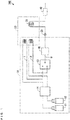
- Fig. 1 is a diagram showing the configuration of the liquid chromatograph according to one embodiment of the present invention.
- the liquid chromatograph 100 of Fig. 1 is an HPLC (High-Performance Liquid Chromatograph).
- the liquid chromatograph 100 includes a mobile phase supply device 10, an injector 20, a column oven 30 and a detector 40.
- the column oven 30 includes a heater.
- a column 31 is stored inside of the column oven 30, and the temperature inside of the column oven 30 is adjusted to a certain constant temperature.
- the mobile phase supply device 10 includes pipes 1, 2, 3, storages 11, 12, a mixer 13, a degassing device 14 and a liquid sender 15. Further, in the present embodiment, the mobile phase supply device 10 includes a portion (the heater) of the column oven 30.
- the storage 11 is a chemical liquid bottle and stores an aqueous solution including salt (hereinafter simply referred to as an aqueous solution).
- the storage 12 is a chemical liquid bottle similar to the storage 11 and stores an organic solvent.
- the storages 11, 12 are examples of first and second storages, respectively.
- the mixer 13 is a low-pressure gradient unit, for example, and includes ports A, B, C.
- the storage 11 and the port A of the mixer 13 are connected to each other by the pipe 1.
- the storage 12 and the port B of the mixer 13 are connected to each other by the pipe 2.
- the pipes 1, 2, are examples of first and second pipes, respectively.
- the pipe 3 is connected to the port C of the mixer 13.
- the mixer 13 produces a mobile phase by mixing the aqueous solution that has been supplied from the storage 11 to the port A through the pipe 1 and the organic solvent that has been supplied from the storage 12 to the port B through the pipe 2, and outputs the produced mobile phase from the port C.
- the upstream and downstream are defined in the liquid chromatograph 100 based on the flow of the aqueous solution or the organic solvent.
- At least respective portions of the respective pipes 1, 2 located at positions further upstream than the mixer 13 are heated such that the temperature of the mixed mobile phase is equal to or higher than the dissolution temperature of salt included in the aqueous solution.
- the respective portions of the respective pipes 1, 2 are arranged in the column oven 30.
- heat exchange can be carried out on the aqueous solution and the organic solvent to make the temperature of the mixed mobile phase be equal to or higher than the dissolution temperature of salt.
- the respective portions of the respective pipes 1, 2 arranged in the column oven 30 may be formed to be loop-like. In this case, the respective portions of the respective pipes 1, 2 arranged in the column oven 30 can be maintained compact while being sufficiently long. As a result, the above-mentioned heat exchange can be more easily carried out.
- the degassing device 14 is provided at the pipes 1, 2 and removes the gas included in the aqueous solution flowing through the pipe 1 and the gas included in the organic solvent flowing through the pipe 2.
- the liquid sender 15 is a pump unit, for example, and is provided at the pipe 3. The liquid sender 15 sends the mobile phase that is output from the port C of the mixer 13 downstream under pressure.
- the injector 20, the column 31 and the detector 40 are provided in this order at positions further downstream than the liquid sender 15 in the pipe 3.
- a sample to be measured is supplied to the injector 20 and introduced into the column 31 together with the mobile phase that is sent by the liquid sender 15 under pressure.
- the sample that has been introduced into the column 31 is separated into its components, and the components are respectively eluted in different lengths of time.
- the detector 40 detects the eluted sample from the column 31.
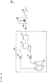
- Fig. 2 is a diagram showing the configuration of a liquid chromatograph 100 according to a first modified example.
- the liquid chromatograph 100 according to the first modified example includes heaters 16, 17.
- the liquid chromatograph 100 according to the first modified example may include the degassing device 14.
- the same also applies to a liquid chromatograph 100 according to the second modified example, described below.
- the heaters 16, 17 may be a hot water bath , an electric heater, a peltier element or the like, and at least respective portions of respective pipes 1, 2 are heated such that the temperature of a mixed mobile phase is equal to or higher than the dissolution temperature of salt included in an aqueous solution. In this case, respective portions of the respective pipes 1, 2 do not have to be arranged in the column oven 30.
- the liquid chromatograph 100 according to the first modified example may include a common heater that heats a mixer 13.
- Fig. 3 is a diagram showing the configuration of a liquid chromatograph 100 according to a second modified example.
- the liquid chromatograph 100 according to the second modified example includes liquid senders 15a, 15b similar to the liquid sender 15 instead of the liquid sender 15.
- a mixer 13 is not a low-pressure gradient unit but a mixer unit, for example.
- the liquid sender 15a is provided at a pipe 1 and sends an aqueous solution stored in a storage 11 towards the mixer 13.
- the liquid sender 15b is provided at a pipe 2 and sends an organic solvent stored in a storage 12 towards the mixer 13.
- the aqueous solution and the organic solvent are sent by separate liquid senders 15a, 15b.
- a sample can be analyzed using a high-pressure gradient method.
- the liquid chromatograph 100 according to the second modified example may include the heaters 16, 17 similar to the heaters of the first modified example or a common heater that heats the mixer 13. In this case, respective portions of the respective pipes 1, 2 do not have to be arranged inside of a column oven 30.
- the mobile phase produced by the mobile phase supply device 10 and the sample are supplied to the injector 20.
- the mobile phase and the sample that have been supplied to the injector 20 are introduced into the column 31 stored in the column oven 30, and the sample that has passed through the column 31 is detected by the detector 40.
- the aqueous solution including salt stored in the storage 11 is led to the mixer 13 through the pipe 1, and the organic solvent stored in the storage 12 is led to the mixer 13 through the pipe 2.
- the mobile phase is produced by the mixture of the aqueous solution and the organic solvent by the mixer 13.
- at least the portion of the pipe 1 and at least the portion of the pipe 2 are stored in the column oven 30.
- At least the portion of the pipe 1 and at least the portion of the pipe 2 are heated by the column oven 30 such that the temperature of the mobile phase produced by the mixer 13 is equal to or higher than the dissolution temperature of salt included in the aqueous solution.
- the aqueous solution and the organic solvent are heated at positions further upstream than the mixer 13 such that the temperature of the mobile phase is equal to or higher than the dissolution temperature of salt included in the aqueous solution. Therefore, even when the aqueous solution comes into contact with the organic solvent, precipitation of salt is prevented regardless of the concentration of the organic solvent. Therefore, salt does not prevent stable supply of the mobile phase. Thus, the mobile phase can be stably supplied.
- the mobile phase supply device 10 can be made compact while the cost of the mobile phase supply device 10 is reduced.
- a pre-cooled phosphate potassium buffer and pre-cooled acetonitrile were used as an aqueous solution and an organic solvent respectively, and a mobile phase was supplied with use of the mobile phase supply device 10 of Fig. 1 .
- a phosphate potassium buffer is referred to as a liquid A
- acetonitrile is referred to as a liquid B.
- the mixer 13 was controlled such that the liquid A and the liquid B were sent at the flow rate ratio of 45:55 from these storages 11, 12.
- the mixer 13 is a low-pressure gradient unit.
- the portion having the length corresponding to 5 mL in each of the pipes 1, 2 was arranged in the column oven 30 such that the liquids A, B that respectively flow through the pipes 1, 2 stayed in the column oven 30 for about 10 minutes and were heated.
- the liquids A and B were heated by the column oven 30, mixed by the mixer 13 and sent downstream by the liquid sender 15.
- Fig. 4 is a diagram showing the temporal change of a pressure indication value of the liquid sender 15 in the inventive example 1.
- the pressure applied by the liquid sender 15 was substantially constant and did not change.
- precipitation of salt did not occur.
- a mobile phase could be stably supplied.
- a mobile phase was supplied similarly to the inventive example 1 by a liquid chromatograph having the configuration similar to that of the mobile phase supply device 10 of Fig. 1 except that the configuration for heating the pipes 1, 2 is not provided. Therefore, the liquids A and B were mixed by the mixer 13 without being heated and then sent downstream by the liquid sender 15.
- Fig. 5 is a diagram showing the temporal change of a pressure indication value of the liquid sender 15 in the comparative example 1.
- the pressure applied by the liquid sender 15 was substantially constant for about 7 minutes after the liquid sending was started and did not change. It was considered that the reason for this was that, because the temperature of the liquid sender 15 at the time of start of liquid sending was high, precipitation of salt did not occur. However, after 7 minutes has elapsed since the start of the liquid sending, the pressure applied by the liquid sender 15 changed little by little and drifted largely. Thus, the mobile phase could not be supplied stably. It was considered that the reason for this was that, because the temperature of the liquid sender 15 has decreased, precipitation of salt occurred.
- a sample was analyzed with use of the liquid chromatograph 100 of Fig. 1 .
- the sample is a thiuram standard liquid, which is an agricultural chemical.
- thiuram standard liquids concentrations of which were 0.1 mg/L, 0.2 mg/L, 0.5 mg/L and 1.0 mg/L, were sequentially supplied to the injector 20 and introduced into the column 31 by the mobile phase that had been produced under the same conditions as those of the inventive example 1.
- the column 31 is an ODS (octadecylsilyl) column, and the temperature of the column 31 is 40 °C.
- the flow rate and the supply rate of the mobile phase are 1.0 mL/min and 20 ⁇ L, respectively.
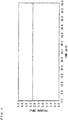
- Fig. 6 is a diagram showing the results of analysis of the samples in the inventive example 2.
- the abscissa indicates the time, and the ordinate indicates the detection intensity of the sample.
- the results of analysis of the samples are indicated by a solid line, a dotted line, a one-dot and dash line and a two-dots and dash line, respectively.
- the baseline of the detection intensity did not change regardless of the concentration of the sample.
- the mobile phase was supplied stably, and the sample was detected and analyzed stably.
- the gradient analysis of a sample was carried out. Specifically, a thiuram standard liquid, the concentration of which was 1.0 mg/L, was used, and the ratio of the liquid A to the liquid B were changed consecutively in the range from 70:30 to 30:70.
- the other analysis conditions were the same as the analysis conditions in the inventive example 2.
- Figs. 7A to 7C are diagrams showing the results of gradient analysis of the samples in the inventive example 3.
- the abscissas in Figs. 7A to 7C indicate the common time
- the ordinate in Fig. 7A indicates the ratio (concentration) of the liquid B
- the ordinate in Fig. 7B indicates an indication value of the pressure applied by the liquid sender 15
- the ordinate in Fig. 7C indicates the detection intensity of the sample.
Landscapes
- Chemical & Material Sciences (AREA)
- Analytical Chemistry (AREA)
- General Health & Medical Sciences (AREA)
- Life Sciences & Earth Sciences (AREA)
- Health & Medical Sciences (AREA)
- Biochemistry (AREA)
- Physics & Mathematics (AREA)
- General Physics & Mathematics (AREA)
- Immunology (AREA)
- Pathology (AREA)
- Chemical Kinetics & Catalysis (AREA)
- Sampling And Sample Adjustment (AREA)
- Treatment Of Liquids With Adsorbents In General (AREA)
Abstract
Description
- The present invention relates to a liquid chromatograph, a mobile phase supply device, a liquid chromatograph analysis method and a mobile phase supply method for supplying a mobile phase.
- In a liquid chromatograph, a liquid mixture of an aqueous solution including salt (hereinafter simply referred to as an aqueous solution) and an organic solvent may be used. For example, the aqueous solution and the organic solvent are mixed in a common bottle in advance, so that a liquid mixture is produced. In this case, precipitation of salt in the aqueous solution hardly occurs. Even if precipitation of salt occurs, it is possible to re-dissolve the salt in the liquid mixture by stirring the liquid mixture in the bottle.
- In the meantime, an aqueous solution and an organic solvent are stored in separate bottles, and a liquid mixture may be produced by mixing of the aqueous solution and the organic solvent that are supplied from the bottle in a common flow path at the time of analysis of a sample. In this case, the concentration of the organic solvent is high at the interface where the aqueous solution and the organic solvent come into contact with each other, so that precipitation of salt is likely to occur. When the concentration of the organic solvent is high, this problem becomes more apparent.
-
JP 2010-156660 A - In the mobile phase supply device described in
JP 2010-156660 A - An object of the present invention is to provide a liquid chromatograph, a mobile phase supply device, a liquid chromatograph analysis method and a mobile phase supply method that enable stable supply of a mobile phase.
- (1) A liquid chromatograph according to one aspect of the present invention includes a mobile phase supply device that produces a mobile phase, an injector to which the mobile phase produced by the mobile phase supply device and a sample are supplied, a column into which the mobile phase and the sample that have been supplied to the injector are introduced, and a detector that detects the sample that has passed through the column, wherein the mobile phase supply device includes a first storage that stores an aqueous solution including salt, a second storage that stores an organic solvent, a mixer that produces the mobile phase by mixing the aqueous solution stored in the first storage with the organic solvent stored in the second storage, a first pipe that connects the mixer to the first storage, a second pipe that connects the mixer to the second storage, and a heater that heats at least a portion of the first pipe and at least a portion of the second pipe such that a temperature of the mobile phase produced by the mixer is equal to or higher than a dissolution temperature of salt included in the aqueous solution.
In this liquid chromatograph, the mobile phase produced by the mobile phase supply device and the sample are supplied to the injector. The mobile phase and the sample that have been supplied to the injector are introduced to the column, and the sample that has passed through the column is detected by the detector.
In the mobile phase supply device, the aqueous solution including salt stored in the first storage is led to the mixer through the first pipe, and the organic solvent stored in the second storage is led to the mixer through the second pipe. The aqueous solution and the organic solvent are mixed by the mixer, so that the mobile phase is produced. Here, at least the portion of the first pipe and at least the portion of the second pipe are heated by the heater such that the temperature of the mobile phase produced by the mixer is equal to or higher than the dissolution temperature of salt included in the aqueous solution.
With this configuration, the aqueous solution and the organic solvent are heated at positions further upstream than the mixer such that the temperature of the mobile phase is equal to or higher than the dissolution temperature of salt included in the aqueous solution. Therefore, even when the aqueous solution and the organic solvent come into contact with each other, precipitation of salt is prevented regardless of the concentration of the organic solvent. Therefore, salt does not prevent stable supply of the mobile phase. Thus, the mobile phase can be stably supplied. - (2) The liquid chromatograph may further include a column oven that stores the column and adjusts a temperature of the column, wherein the column oven may include the heater and heat at least the portion of the first pipe and at least the portion of the second pipe while further storing at least the portion of the first pipe and at least the portion of the second pipe. In this case, it is not necessary to provide the heater for heating at least the portion of the first pipe and at least the portion of the second pipe separately from the column oven. Thus, the mobile phase supply device can be made compact while the cost of the mobile phase supply device is reduced.
- (3) A mobile phase supply device according to another aspect of the present invention that supplies a mobile phase to be used in liquid chromatograph analysis of a sample includes a first storage that stores an aqueous solution including salt, a second storage that stores an organic solvent, a mixer that produces a mobile phase by mixing the aqueous solution stored in the first storage with the organic solvent stored in the second storage, a first pipe that connects the mixer to the first storage, a second pipe that connects the mixer to the second storage, and a heater that heats at least a portion of the first pipe and at least a portion of the second pipe such that a temperature of the mobile phase produced by the mixer is equal to or higher than a dissolution temperature of salt included in the aqueous solution.
In this mobile phase supply device, even when the aqueous solution comes into contact with the organic solvent, precipitation of salt is prevented regardless of the concentration of the organic solvent. Therefore, salt does not prevent stable supply of the mobile phase. Thus, the mobile phase can be stably supplied. - (4) A liquid chromatograph analysis method according to yet another aspect of the present invention includes producing a mobile phase by a mobile phase supply device, supplying the mobile phase produced by the mobile phase supply device and a sample to an injector, introducing the mobile phase and the sample that have been supplied to the injector to a column, and detecting the sample that has passed through the column by a detector, wherein the producing the mobile phase by the mobile phase supply device includes leading an aqueous solution including salt stored in a first storage to a mixer through a first pipe, leading an organic solvent stored in a second storage to the mixer through a second pipe, producing the mobile phase by mixing the aqueous solution and the organic solvent by the mixer, and heating at least a portion of the first pipe and at least a portion of the second pipe by a heater such that a temperature of the mobile phase produced by the mixer is equal to or higher than a dissolution temperature of salt included in the aqueous solution.
This liquid chromatograph analysis method prevents precipitation of salt regardless of the concentration of the organic solvent even when the aqueous solution and the organic solvent come into contact with each other in the mobile phase supply device. Therefore, salt does not prevent stable supply of the mobile phase. Thus, the mobile phase can be stably supplied. - (5) The liquid chromatograph analysis method may further include adjusting a temperature of the column by a column oven storing the column, wherein the column oven may include the heater, and the heating at least the portion of the first pipe and at least the portion of the second pipe may include storing at least the portion of the first pipe and at least the portion of the second pipe in the column oven, and heating at least the portion of the first pipe and at least the portion of the second pipe by the column oven. In this case, the mobile phase supply device can be made compact while the cost of the mobile phase supply device is reduced.
- (6) A mobile phase supply method according to yet another aspect of the present invention of supplying a mobile phase to be used in liquid chromatograph analysis of a sample includes leading an aqueous solution including salt stored in a first storage to a mixer through a first pipe, leading an organic solvent stored in a second storage to the mixer through a second pipe, producing the mobile phase by mixing the aqueous solution and the organic solvent by the mixer, and heating at least a portion of the first pipe and at least a portion of the second pipe by a heater such that a temperature of the mobile phase produced by the mixer is equal to or higher than a dissolution temperature of salt included in the aqueous solution.
- Even when the aqueous solution and the organic solvent come into contact with each other, this mobile phase supply method prevents precipitation of salt regardless of the concentration of the organic solvent. Therefore, salt does not prevent stable supply of the mobile phase. Thus, the mobile phase can be stably supplied.
- Other features, elements, characteristics, and advantages of the present invention will become more apparent from the following description of preferred embodiments of the present invention with reference to the attached drawings.
-
-
Fig. 1 is a diagram showing the configuration of a liquid chromatograph according to one embodiment of the present invention; -
Fig. 2 is a diagram showing the configuration of a liquid chromatograph according to a first modified example; -
Fig. 3 is a diagram showing the configuration of a liquid chromatograph according to a second modified example; -
Fig. 4 is a diagram showing the temporal change of a pressure indication value of a liquid sender in an inventive example 1; -
Fig. 5 is a diagram showing the temporal change of a pressure indication value of the liquid sender in a comparative example 1; -
Fig. 6 is a diagram showing the results of analysis of samples in an inventive example 2; and -
Figs. 7A to 7C are diagrams showing the results of gradient analysis of samples in an inventive example 3. - Details of a mobile phase supply device, a liquid chromatograph, a mobile phase supply method and a liquid chromatograph analysis method according to an embodiment of the present invention will be described below with reference to drawings.
Fig. 1 is a diagram showing the configuration of the liquid chromatograph according to one embodiment of the present invention. Theliquid chromatograph 100 ofFig. 1 is an HPLC (High-Performance Liquid Chromatograph). - As shown in
Fig. 1 , theliquid chromatograph 100 includes a mobilephase supply device 10, aninjector 20, acolumn oven 30 and adetector 40. Thecolumn oven 30 includes a heater. Acolumn 31 is stored inside of thecolumn oven 30, and the temperature inside of thecolumn oven 30 is adjusted to a certain constant temperature. - The mobile
phase supply device 10 includespipes storages mixer 13, adegassing device 14 and aliquid sender 15. Further, in the present embodiment, the mobilephase supply device 10 includes a portion (the heater) of thecolumn oven 30. Thestorage 11 is a chemical liquid bottle and stores an aqueous solution including salt (hereinafter simply referred to as an aqueous solution). Thestorage 12 is a chemical liquid bottle similar to thestorage 11 and stores an organic solvent. Thestorages - The
mixer 13 is a low-pressure gradient unit, for example, and includes ports A, B, C. Thestorage 11 and the port A of themixer 13 are connected to each other by thepipe 1. Thestorage 12 and the port B of themixer 13 are connected to each other by thepipe 2. Thepipes pipe 3 is connected to the port C of themixer 13. Themixer 13 produces a mobile phase by mixing the aqueous solution that has been supplied from thestorage 11 to the port A through thepipe 1 and the organic solvent that has been supplied from thestorage 12 to the port B through thepipe 2, and outputs the produced mobile phase from the port C. - In the following description, the upstream and downstream are defined in the
liquid chromatograph 100 based on the flow of the aqueous solution or the organic solvent. At least respective portions of therespective pipes mixer 13 are heated such that the temperature of the mixed mobile phase is equal to or higher than the dissolution temperature of salt included in the aqueous solution. In the present embodiment, the respective portions of therespective pipes column oven 30. Thus, in thecolumn oven 30, heat exchange can be carried out on the aqueous solution and the organic solvent to make the temperature of the mixed mobile phase be equal to or higher than the dissolution temperature of salt. - The respective portions of the
respective pipes column oven 30 may be formed to be loop-like. In this case, the respective portions of therespective pipes column oven 30 can be maintained compact while being sufficiently long. As a result, the above-mentioned heat exchange can be more easily carried out. - The
degassing device 14 is provided at thepipes pipe 1 and the gas included in the organic solvent flowing through thepipe 2. Theliquid sender 15 is a pump unit, for example, and is provided at thepipe 3. Theliquid sender 15 sends the mobile phase that is output from the port C of themixer 13 downstream under pressure. - The
injector 20, thecolumn 31 and thedetector 40 are provided in this order at positions further downstream than theliquid sender 15 in thepipe 3. A sample to be measured is supplied to theinjector 20 and introduced into thecolumn 31 together with the mobile phase that is sent by theliquid sender 15 under pressure. The sample that has been introduced into thecolumn 31 is separated into its components, and the components are respectively eluted in different lengths of time. Thedetector 40 detects the eluted sample from thecolumn 31. -
Fig. 2 is a diagram showing the configuration of aliquid chromatograph 100 according to a first modified example. As shown inFig. 2 , theliquid chromatograph 100 according to the first modified example includesheaters degassing device 14, theliquid chromatograph 100 according to the first modified example may include thedegassing device 14. The same also applies to aliquid chromatograph 100 according to the second modified example, described below. - The
heaters respective pipes respective pipes column oven 30. Instead of theheaters liquid chromatograph 100 according to the first modified example may include a common heater that heats amixer 13. -
Fig. 3 is a diagram showing the configuration of aliquid chromatograph 100 according to a second modified example. As shown inFig. 3 , theliquid chromatograph 100 according to the second modified example includesliquid senders liquid sender 15 instead of theliquid sender 15. Further, amixer 13 is not a low-pressure gradient unit but a mixer unit, for example. - The
liquid sender 15a is provided at apipe 1 and sends an aqueous solution stored in astorage 11 towards themixer 13. Theliquid sender 15b is provided at apipe 2 and sends an organic solvent stored in astorage 12 towards themixer 13. In this case, the aqueous solution and the organic solvent are sent by separateliquid senders - The
liquid chromatograph 100 according to the second modified example may include theheaters mixer 13. In this case, respective portions of therespective pipes column oven 30. - In the
liquid chromatograph 100 according to the present embodiment, the mobile phase produced by the mobilephase supply device 10 and the sample are supplied to theinjector 20. The mobile phase and the sample that have been supplied to theinjector 20 are introduced into thecolumn 31 stored in thecolumn oven 30, and the sample that has passed through thecolumn 31 is detected by thedetector 40. - In the mobile
phase supply device 10, the aqueous solution including salt stored in thestorage 11 is led to themixer 13 through thepipe 1, and the organic solvent stored in thestorage 12 is led to themixer 13 through thepipe 2. The mobile phase is produced by the mixture of the aqueous solution and the organic solvent by themixer 13. Here, at least the portion of thepipe 1 and at least the portion of thepipe 2 are stored in thecolumn oven 30. At least the portion of thepipe 1 and at least the portion of thepipe 2 are heated by thecolumn oven 30 such that the temperature of the mobile phase produced by themixer 13 is equal to or higher than the dissolution temperature of salt included in the aqueous solution. - With this configuration, the aqueous solution and the organic solvent are heated at positions further upstream than the
mixer 13 such that the temperature of the mobile phase is equal to or higher than the dissolution temperature of salt included in the aqueous solution. Therefore, even when the aqueous solution comes into contact with the organic solvent, precipitation of salt is prevented regardless of the concentration of the organic solvent. Therefore, salt does not prevent stable supply of the mobile phase. Thus, the mobile phase can be stably supplied. - Further, because at least the portion of the
pipe 1 and at least the portion of thepipe 2 are heated by thecolumn oven 30 in the present embodiment, it is not necessary to provide a heater separately from thecolumn oven 30. Thus, the mobilephase supply device 10 can be made compact while the cost of the mobilephase supply device 10 is reduced. - In an inventive example 1, a pre-cooled phosphate potassium buffer and pre-cooled acetonitrile were used as an aqueous solution and an organic solvent respectively, and a mobile phase was supplied with use of the mobile
phase supply device 10 ofFig. 1 . Hereinafter, a phosphate potassium buffer is referred to as a liquid A, and acetonitrile is referred to as a liquid B. The same applies to a comparative example 1 and inventive examples 2 and 3, described below. - Specifically, in the inventive example 1, 50 mmol/L of the liquid A was stored in the
storage 11, and 50 mmol/L of the liquid B was stored in thestorage 12. Themixer 13 was controlled such that the liquid A and the liquid B were sent at the flow rate ratio of 45:55 from thesestorages mixer 13 is a low-pressure gradient unit. - Further, the portion having the length corresponding to 5 mL in each of the
pipes column oven 30 such that the liquids A, B that respectively flow through thepipes column oven 30 for about 10 minutes and were heated. The liquids A and B were heated by thecolumn oven 30, mixed by themixer 13 and sent downstream by theliquid sender 15. -
Fig. 4 is a diagram showing the temporal change of a pressure indication value of theliquid sender 15 in the inventive example 1. As shown inFig. 4 , in the inventive example 1, the pressure applied by theliquid sender 15 was substantially constant and did not change. Thus, in the inventive example 1, even when the liquids A and B were mixed, precipitation of salt did not occur. Thus, it was confirmed that a mobile phase could be stably supplied. - In the meantime, in the comparative example 1, a mobile phase was supplied similarly to the inventive example 1 by a liquid chromatograph having the configuration similar to that of the mobile
phase supply device 10 ofFig. 1 except that the configuration for heating thepipes mixer 13 without being heated and then sent downstream by theliquid sender 15. -
Fig. 5 is a diagram showing the temporal change of a pressure indication value of theliquid sender 15 in the comparative example 1. As shown inFig. 5 , in the comparative example 1, the pressure applied by theliquid sender 15 was substantially constant for about 7 minutes after the liquid sending was started and did not change. It was considered that the reason for this was that, because the temperature of theliquid sender 15 at the time of start of liquid sending was high, precipitation of salt did not occur. However, after 7 minutes has elapsed since the start of the liquid sending, the pressure applied by theliquid sender 15 changed little by little and drifted largely. Thus, the mobile phase could not be supplied stably. It was considered that the reason for this was that, because the temperature of theliquid sender 15 has decreased, precipitation of salt occurred. - In the inventive example 2, a sample was analyzed with use of the
liquid chromatograph 100 ofFig. 1 . The sample is a thiuram standard liquid, which is an agricultural chemical. Specifically, thiuram standard liquids, concentrations of which were 0.1 mg/L, 0.2 mg/L, 0.5 mg/L and 1.0 mg/L, were sequentially supplied to theinjector 20 and introduced into thecolumn 31 by the mobile phase that had been produced under the same conditions as those of the inventive example 1. Here, thecolumn 31 is an ODS (octadecylsilyl) column, and the temperature of thecolumn 31 is 40 °C. The flow rate and the supply rate of the mobile phase are 1.0 mL/min and 20 µL, respectively. -
Fig. 6 is a diagram showing the results of analysis of the samples in the inventive example 2. InFig. 6 , the abscissa indicates the time, and the ordinate indicates the detection intensity of the sample. Further, the results of analysis of the samples, the concentrations of which are 0.1 mg/L, 0.2 mg/L, 0.5 mg/L and 1.0 mg/L, are indicated by a solid line, a dotted line, a one-dot and dash line and a two-dots and dash line, respectively. As shown inFig. 6 , in the inventive example 2, the baseline of the detection intensity did not change regardless of the concentration of the sample. Thus, it was confirmed that the mobile phase was supplied stably, and the sample was detected and analyzed stably. - In the inventive example 3, the gradient analysis of a sample was carried out. Specifically, a thiuram standard liquid, the concentration of which was 1.0 mg/L, was used, and the ratio of the liquid A to the liquid B were changed consecutively in the range from 70:30 to 30:70. The other analysis conditions were the same as the analysis conditions in the inventive example 2.
-
Figs. 7A to 7C are diagrams showing the results of gradient analysis of the samples in the inventive example 3. The abscissas inFigs. 7A to 7C indicate the common time, the ordinate inFig. 7A indicates the ratio (concentration) of the liquid B, the ordinate inFig. 7B indicates an indication value of the pressure applied by theliquid sender 15, and the ordinate inFig. 7C indicates the detection intensity of the sample. - As shown in
Figs. 7A and 7B , even when the concentration of the liquid B was increased from 30 % to 70 %, the pressure applied by theliquid sender 15 did not change little by little. Thus, even when the liquid A was mixed with the liquid B having a high concentration, precipitation of salt did not occur. Therefore, it was confirmed that the mobile phase could be supplied stably. Further, as shown inFig. 7C , the baseline of the detection intensity did not change. Thus, it was confirmed that the sample was detected stably and the gradient analysis was performed stably. - While preferred embodiments of the present invention have been described above, it is to be understood that variations and modifications will be apparent to those skilled in the art without departing the scope and spirit of the present invention. The scope of the present invention, therefore, is to be determined solely by the following claims.
Claims (6)
- A liquid chromatograph comprising:a mobile phase supply device that produces a mobile phase;an injector to which the mobile phase produced by the mobile phase supply device and a sample are supplied;a column into which the mobile phase and the sample that have been supplied to the injector are introduced; anda detector that detects the sample that has passed through the column, whereinthe mobile phase supply device includesa first storage that stores an aqueous solution including salt,a second storage that stores an organic solvent,a mixer that produces the mobile phase by mixing the aqueous solution stored in the first storage with the organic solvent stored in the second storage,a first pipe that connects the mixer to the first storage,a second pipe that connects the mixer to the second storage, anda heater that heats at least a portion of the first pipe and at least a portion of the second pipe such that a temperature of the mobile phase produced by the mixer is equal to or higher than a dissolution temperature of salt included in the aqueous solution.
- The liquid chromatograph according to claim 1, further comprising a column oven that stores the column and adjusts a temperature of the column, wherein
the column oven includes the heater and heats at least the portion of the first pipe and at least the portion of the second pipe while further storing at least the portion of the first pipe and at least the portion of the second pipe. - A mobile phase supply device that supplies a mobile phase to be used in liquid chromatograph analysis of a sample, comprising:a first storage that stores an aqueous solution including salt;a second storage that stores an organic solvent;a mixer that produces a mobile phase by mixing the aqueous solution stored in the first storage with the organic solvent stored in the second storage;a first pipe that connects the mixer to the first storage;a second pipe that connects the mixer to the second storage; anda heater that heats at least a portion of the first pipe and at least a portion of the second pipe such that a temperature of the mobile phase produced by the mixer is equal to or higher than a dissolution temperature of salt included in the aqueous solution.
- A liquid chromatograph analysis method including:producing a mobile phase by a mobile phase supply device;supplying the mobile phase produced by the mobile phase supply device and a sample to an injector;introducing the mobile phase and the sample that have been supplied to the injector to a column; anddetecting the sample that has passed through the column by a detector, whereinthe producing the mobile phase by the mobile phase supply device includesleading an aqueous solution including salt stored in a first storage to a mixer through a first pipe,leading an organic solvent stored in a second storage to the mixer through a second pipe,producing the mobile phase by mixing the aqueous solution and the organic solvent by the mixer, andheating at least a portion of the first pipe and at least a portion of the second pipe by a heater such that a temperature of the mobile phase produced by the mixer is equal to or higher than a dissolution temperature of salt included in the aqueous solution.
- The liquid chromatograph analysis method according to claim 4, further including adjusting a temperature of the column by a column oven storing the column, wherein
the column oven includes the heater, and
the heating at least the portion of the first pipe and at least the portion of the second pipe includes
storing at least the portion of the first pipe and at least the portion of the second pipe in the column oven, and
heating at least the portion of the first pipe and at least the portion of the second pipe by the column oven. - A mobile phase supply method of supplying a mobile phase to be used in liquid chromatograph analysis of a sample, including:leading an aqueous solution including salt stored in a first storage to a mixer through a first pipe;leading an organic solvent stored in a second storage to the mixer through a second pipe;producing the mobile phase by mixing the aqueous solution and the organic solvent by the mixer; andheating at least a portion of the first pipe and at least a portion of the second pipe by a heater such that a temperature of the mobile phase produced by the mixer is equal to or higher than a dissolution temperature of salt included in the aqueous solution.
Applications Claiming Priority (1)
| Application Number | Priority Date | Filing Date | Title |
|---|---|---|---|
| JP2018155792A JP7070238B2 (en) | 2018-08-22 | 2018-08-22 | Liquid chromatograph analyzer, mobile phase feeder, liquid chromatograph analysis method and mobile phase supply method |
Publications (2)
| Publication Number | Publication Date |
|---|---|
| EP3614139A1 true EP3614139A1 (en) | 2020-02-26 |
| EP3614139B1 EP3614139B1 (en) | 2025-03-12 |
Family
ID=67614433
Family Applications (1)
| Application Number | Title | Priority Date | Filing Date |
|---|---|---|---|
| EP19191160.1A Active EP3614139B1 (en) | 2018-08-22 | 2019-08-12 | Liquid chromatograph, mobile phase supply device, liquid chromatograph analysis method and mobile phase supply method |
Country Status (4)
| Country | Link |
|---|---|
| US (1) | US11364453B2 (en) |
| EP (1) | EP3614139B1 (en) |
| JP (1) | JP7070238B2 (en) |
| CN (1) | CN110857934A (en) |
Families Citing this family (1)
| Publication number | Priority date | Publication date | Assignee | Title |
|---|---|---|---|---|
| US11604174B2 (en) * | 2018-11-16 | 2023-03-14 | Waters Technologies Corporation | System and method for monitoring phase-separation and mutual miscibility of fluid mixtures |
Citations (4)
| Publication number | Priority date | Publication date | Assignee | Title |
|---|---|---|---|---|
| US20060054558A1 (en) * | 2002-02-22 | 2006-03-16 | Brian Jones | Mobile phase treatment for chromatography |
| JP2010156660A (en) | 2009-01-05 | 2010-07-15 | Shimadzu Corp | Mobile phase supply apparatus and liquid chromatograph using the same |
| GB2495777A (en) * | 2011-10-21 | 2013-04-24 | Agilent Technologies Inc | Flow sensor stabilisation by adjusting temperature gradient |
| US20130134079A1 (en) * | 2011-11-28 | 2013-05-30 | Waters Technologies Corporation | Mobile phase solvent delivery module |
Family Cites Families (19)
| Publication number | Priority date | Publication date | Assignee | Title |
|---|---|---|---|---|
| IL56510A (en) * | 1979-01-26 | 1982-04-30 | Solmat Syst | Method of utilizing solar ponds for effecting controlled temperature changes of solution |
| US4395385A (en) * | 1980-11-24 | 1983-07-26 | Kerr-Mcgee Refining Corporation | Process for removing hydrogen sulfide from sour gas streams |
| US4492637A (en) * | 1983-11-25 | 1985-01-08 | The Board Of Regents Of The University Of Nebraska | Water separation process |
| JP2564886B2 (en) * | 1988-03-31 | 1996-12-18 | 株式会社島津製作所 | Liquid chromatograph mass spectrometer |
| US6720186B1 (en) | 1998-04-03 | 2004-04-13 | Symyx Technologies, Inc. | Method of research for creating and testing novel catalysts, reactions and polymers |
| US6406632B1 (en) | 1998-04-03 | 2002-06-18 | Symyx Technologies, Inc. | Rapid characterization of polymers |
| US6294388B1 (en) | 1998-04-03 | 2001-09-25 | Symyx Technologies, Inc. | Indirect calibration of polymer characterization systems |
| US6265226B1 (en) | 1998-04-03 | 2001-07-24 | Symyx Technologies, Inc. | Automated sampling methods for rapid characterization of polymers |
| US6260407B1 (en) | 1998-04-03 | 2001-07-17 | Symyx Technologies, Inc. | High-temperature characterization of polymers |
| US6175409B1 (en) | 1999-04-02 | 2001-01-16 | Symyx Technologies, Inc. | Flow-injection analysis and variable-flow light-scattering methods and apparatus for characterizing polymers |
| US6416663B1 (en) | 1998-04-03 | 2002-07-09 | Symyx Technologies, Inc. | Chromatographic column for rapid characterizations of polymers |
| JP4569633B2 (en) * | 2006-02-09 | 2010-10-27 | 株式会社島津製作所 | Analysis method and apparatus by liquid chromatography |
| JP2008232729A (en) | 2007-03-19 | 2008-10-02 | Isuzu Motors Ltd | Liquid chromatograph analysis apparatus and method |
| JP5685381B2 (en) * | 2009-03-13 | 2015-03-18 | Jcrファーマ株式会社 | Analysis method of saccharides |
| KR20180000341A (en) * | 2009-06-16 | 2018-01-02 | 젠자임 코포레이션 | Improved methods for purification of recombinant aav vectors |
| JP2013195392A (en) | 2012-03-22 | 2013-09-30 | Hitachi High-Technologies Corp | Liquid chromatograph analyzer and temperature control method of the same |
| JP6127790B2 (en) | 2013-07-12 | 2017-05-17 | 株式会社島津製作所 | Control device and control method for liquid chromatograph |
| JP6260351B2 (en) * | 2014-03-04 | 2018-01-17 | 株式会社島津製作所 | Chromatograph data processing apparatus and data processing method |
| JP2017133971A (en) * | 2016-01-28 | 2017-08-03 | 昭和電工株式会社 | Pretreatment method of liquid chromatography analysis device, and liquid chromatography analysis method |
-
2018
- 2018-08-22 JP JP2018155792A patent/JP7070238B2/en active Active
-
2019
- 2019-08-12 EP EP19191160.1A patent/EP3614139B1/en active Active
- 2019-08-21 US US16/546,409 patent/US11364453B2/en active Active
- 2019-08-22 CN CN201910778900.1A patent/CN110857934A/en active Pending
Patent Citations (4)
| Publication number | Priority date | Publication date | Assignee | Title |
|---|---|---|---|---|
| US20060054558A1 (en) * | 2002-02-22 | 2006-03-16 | Brian Jones | Mobile phase treatment for chromatography |
| JP2010156660A (en) | 2009-01-05 | 2010-07-15 | Shimadzu Corp | Mobile phase supply apparatus and liquid chromatograph using the same |
| GB2495777A (en) * | 2011-10-21 | 2013-04-24 | Agilent Technologies Inc | Flow sensor stabilisation by adjusting temperature gradient |
| US20130134079A1 (en) * | 2011-11-28 | 2013-05-30 | Waters Technologies Corporation | Mobile phase solvent delivery module |
Also Published As
| Publication number | Publication date |
|---|---|
| EP3614139B1 (en) | 2025-03-12 |
| CN110857934A (en) | 2020-03-03 |
| US20200061494A1 (en) | 2020-02-27 |
| JP7070238B2 (en) | 2022-05-18 |
| JP2020030107A (en) | 2020-02-27 |
| US11364453B2 (en) | 2022-06-21 |
Similar Documents
| Publication | Publication Date | Title |
|---|---|---|
| CN105986993B (en) | Liquefied carbon dioxide liquid delivery pump and supercritical fluid chromatograph equipped with the same | |
| US11364453B2 (en) | Liquid chromatograph, mobile phase supply device, liquid chromatograph analysis method and mobile phase supply method | |
| US10648680B2 (en) | Hot water supply system having preheating function and method for controlling same | |
| JP4645437B2 (en) | Gradient liquid feeder | |
| TWI760465B (en) | Urea quantifying method and analysis device | |
| EP3822640B1 (en) | Automated analyzer | |
| JP4569633B2 (en) | Analysis method and apparatus by liquid chromatography | |
| CA2569728A1 (en) | Interface from a thermal desorption unit to a chromatographic column | |
| CN107430099B (en) | supercritical fluid device | |
| JP2016114574A (en) | Supercritical fluid separator | |
| TWI771528B (en) | Urea analysis method and analysis device | |
| US11465074B2 (en) | Degassing device | |
| CN116609443A (en) | Amino acid analysis method and liquid chromatograph | |
| JP7342946B2 (en) | Liquefied carbon dioxide supply equipment and supercritical fluid equipment | |
| JP4504721B2 (en) | Liquid chromatography equipment | |
| JP2573671B2 (en) | Mobile phase feeder for supercritical fluid chromatography | |
| JP2021121820A (en) | Supercritical fluid chromatograph | |
| JPWO2018207258A1 (en) | Gas chromatograph | |
| KR101809702B1 (en) | On-line Contamination Monitoring System and Method using it | |
| US20200209199A1 (en) | Supercritical fluid apparatus | |
| CN207408358U (en) | A kind of on-line chromatograph detects tubular reactor system | |
| WO2021117204A1 (en) | Chromatography system | |
| US20240159717A1 (en) | Pump unit for chromatograph | |
| JP2025522966A (en) | Sample supply system for analytical instruments | |
| US20040126276A1 (en) | Transport device |
Legal Events
| Date | Code | Title | Description |
|---|---|---|---|
| PUAI | Public reference made under article 153(3) epc to a published international application that has entered the european phase |
Free format text: ORIGINAL CODE: 0009012 |
|
| STAA | Information on the status of an ep patent application or granted ep patent |
Free format text: STATUS: REQUEST FOR EXAMINATION WAS MADE |
|
| 17P | Request for examination filed |
Effective date: 20190814 |
|
| AK | Designated contracting states |
Kind code of ref document: A1 Designated state(s): AL AT BE BG CH CY CZ DE DK EE ES FI FR GB GR HR HU IE IS IT LI LT LU LV MC MK MT NL NO PL PT RO RS SE SI SK SM TR |
|
| AX | Request for extension of the european patent |
Extension state: BA ME |
|
| RBV | Designated contracting states (corrected) |
Designated state(s): AL AT BE BG CH CY CZ DE DK EE ES FI FR GB GR HR HU IE IS IT LI LT LU LV MC MK MT NL NO PL PT RO RS SE SI SK SM TR |
|
| STAA | Information on the status of an ep patent application or granted ep patent |
Free format text: STATUS: EXAMINATION IS IN PROGRESS |
|
| 17Q | First examination report despatched |
Effective date: 20221027 |
|
| GRAP | Despatch of communication of intention to grant a patent |
Free format text: ORIGINAL CODE: EPIDOSNIGR1 |
|
| STAA | Information on the status of an ep patent application or granted ep patent |
Free format text: STATUS: GRANT OF PATENT IS INTENDED |
|
| INTG | Intention to grant announced |
Effective date: 20241014 |
|
| GRAS | Grant fee paid |
Free format text: ORIGINAL CODE: EPIDOSNIGR3 |
|
| GRAA | (expected) grant |
Free format text: ORIGINAL CODE: 0009210 |
|
| STAA | Information on the status of an ep patent application or granted ep patent |
Free format text: STATUS: THE PATENT HAS BEEN GRANTED |
|
| AK | Designated contracting states |
Kind code of ref document: B1 Designated state(s): AL AT BE BG CH CY CZ DE DK EE ES FI FR GB GR HR HU IE IS IT LI LT LU LV MC MK MT NL NO PL PT RO RS SE SI SK SM TR |
|
| REG | Reference to a national code |
Ref country code: GB Ref legal event code: FG4D |
|
| REG | Reference to a national code |
Ref country code: CH Ref legal event code: EP |
|
| REG | Reference to a national code |
Ref country code: DE Ref legal event code: R096 Ref document number: 602019067105 Country of ref document: DE |
|
| REG | Reference to a national code |
Ref country code: IE Ref legal event code: FG4D |
|
| PG25 | Lapsed in a contracting state [announced via postgrant information from national office to epo] |
Ref country code: RS Free format text: LAPSE BECAUSE OF FAILURE TO SUBMIT A TRANSLATION OF THE DESCRIPTION OR TO PAY THE FEE WITHIN THE PRESCRIBED TIME-LIMIT Effective date: 20250612 |
|
| PG25 | Lapsed in a contracting state [announced via postgrant information from national office to epo] |
Ref country code: FI Free format text: LAPSE BECAUSE OF FAILURE TO SUBMIT A TRANSLATION OF THE DESCRIPTION OR TO PAY THE FEE WITHIN THE PRESCRIBED TIME-LIMIT Effective date: 20250312 |
|
| PG25 | Lapsed in a contracting state [announced via postgrant information from national office to epo] |
Ref country code: ES Free format text: LAPSE BECAUSE OF FAILURE TO SUBMIT A TRANSLATION OF THE DESCRIPTION OR TO PAY THE FEE WITHIN THE PRESCRIBED TIME-LIMIT Effective date: 20250312 |
|
| REG | Reference to a national code |
Ref country code: LT Ref legal event code: MG9D |
|
| PG25 | Lapsed in a contracting state [announced via postgrant information from national office to epo] |
Ref country code: NO Free format text: LAPSE BECAUSE OF FAILURE TO SUBMIT A TRANSLATION OF THE DESCRIPTION OR TO PAY THE FEE WITHIN THE PRESCRIBED TIME-LIMIT Effective date: 20250612 |
|
| PG25 | Lapsed in a contracting state [announced via postgrant information from national office to epo] |
Ref country code: HR Free format text: LAPSE BECAUSE OF FAILURE TO SUBMIT A TRANSLATION OF THE DESCRIPTION OR TO PAY THE FEE WITHIN THE PRESCRIBED TIME-LIMIT Effective date: 20250312 |
|
| REG | Reference to a national code |
Ref country code: NL Ref legal event code: MP Effective date: 20250312 |
|
| PG25 | Lapsed in a contracting state [announced via postgrant information from national office to epo] |
Ref country code: LV Free format text: LAPSE BECAUSE OF FAILURE TO SUBMIT A TRANSLATION OF THE DESCRIPTION OR TO PAY THE FEE WITHIN THE PRESCRIBED TIME-LIMIT Effective date: 20250312 |
|
| PG25 | Lapsed in a contracting state [announced via postgrant information from national office to epo] |
Ref country code: GR Free format text: LAPSE BECAUSE OF FAILURE TO SUBMIT A TRANSLATION OF THE DESCRIPTION OR TO PAY THE FEE WITHIN THE PRESCRIBED TIME-LIMIT Effective date: 20250613 Ref country code: BG Free format text: LAPSE BECAUSE OF FAILURE TO SUBMIT A TRANSLATION OF THE DESCRIPTION OR TO PAY THE FEE WITHIN THE PRESCRIBED TIME-LIMIT Effective date: 20250312 |
|
| REG | Reference to a national code |
Ref country code: AT Ref legal event code: MK05 Ref document number: 1775391 Country of ref document: AT Kind code of ref document: T Effective date: 20250312 |
|
| PG25 | Lapsed in a contracting state [announced via postgrant information from national office to epo] |
Ref country code: NL Free format text: LAPSE BECAUSE OF FAILURE TO SUBMIT A TRANSLATION OF THE DESCRIPTION OR TO PAY THE FEE WITHIN THE PRESCRIBED TIME-LIMIT Effective date: 20250312 |
|
| PG25 | Lapsed in a contracting state [announced via postgrant information from national office to epo] |
Ref country code: SE Free format text: LAPSE BECAUSE OF FAILURE TO SUBMIT A TRANSLATION OF THE DESCRIPTION OR TO PAY THE FEE WITHIN THE PRESCRIBED TIME-LIMIT Effective date: 20250312 |
|
| PG25 | Lapsed in a contracting state [announced via postgrant information from national office to epo] |
Ref country code: SM Free format text: LAPSE BECAUSE OF FAILURE TO SUBMIT A TRANSLATION OF THE DESCRIPTION OR TO PAY THE FEE WITHIN THE PRESCRIBED TIME-LIMIT Effective date: 20250312 |
|
| PG25 | Lapsed in a contracting state [announced via postgrant information from national office to epo] |
Ref country code: PT Free format text: LAPSE BECAUSE OF FAILURE TO SUBMIT A TRANSLATION OF THE DESCRIPTION OR TO PAY THE FEE WITHIN THE PRESCRIBED TIME-LIMIT Effective date: 20250714 |
|
| PGFP | Annual fee paid to national office [announced via postgrant information from national office to epo] |
Ref country code: DE Payment date: 20250702 Year of fee payment: 7 |
|
| PG25 | Lapsed in a contracting state [announced via postgrant information from national office to epo] |
Ref country code: IT Free format text: LAPSE BECAUSE OF FAILURE TO SUBMIT A TRANSLATION OF THE DESCRIPTION OR TO PAY THE FEE WITHIN THE PRESCRIBED TIME-LIMIT Effective date: 20250312 Ref country code: PL Free format text: LAPSE BECAUSE OF FAILURE TO SUBMIT A TRANSLATION OF THE DESCRIPTION OR TO PAY THE FEE WITHIN THE PRESCRIBED TIME-LIMIT Effective date: 20250312 |
|
| PGFP | Annual fee paid to national office [announced via postgrant information from national office to epo] |
Ref country code: GB Payment date: 20250703 Year of fee payment: 7 |
|
| PG25 | Lapsed in a contracting state [announced via postgrant information from national office to epo] |
Ref country code: AT Free format text: LAPSE BECAUSE OF FAILURE TO SUBMIT A TRANSLATION OF THE DESCRIPTION OR TO PAY THE FEE WITHIN THE PRESCRIBED TIME-LIMIT Effective date: 20250312 |
|
| PG25 | Lapsed in a contracting state [announced via postgrant information from national office to epo] |
Ref country code: CZ Free format text: LAPSE BECAUSE OF FAILURE TO SUBMIT A TRANSLATION OF THE DESCRIPTION OR TO PAY THE FEE WITHIN THE PRESCRIBED TIME-LIMIT Effective date: 20250312 Ref country code: EE Free format text: LAPSE BECAUSE OF FAILURE TO SUBMIT A TRANSLATION OF THE DESCRIPTION OR TO PAY THE FEE WITHIN THE PRESCRIBED TIME-LIMIT Effective date: 20250312 |
|
| PG25 | Lapsed in a contracting state [announced via postgrant information from national office to epo] |
Ref country code: RO Free format text: LAPSE BECAUSE OF FAILURE TO SUBMIT A TRANSLATION OF THE DESCRIPTION OR TO PAY THE FEE WITHIN THE PRESCRIBED TIME-LIMIT Effective date: 20250312 |
|
| PG25 | Lapsed in a contracting state [announced via postgrant information from national office to epo] |
Ref country code: SK Free format text: LAPSE BECAUSE OF FAILURE TO SUBMIT A TRANSLATION OF THE DESCRIPTION OR TO PAY THE FEE WITHIN THE PRESCRIBED TIME-LIMIT Effective date: 20250312 |
|
| PG25 | Lapsed in a contracting state [announced via postgrant information from national office to epo] |
Ref country code: IS Free format text: LAPSE BECAUSE OF FAILURE TO SUBMIT A TRANSLATION OF THE DESCRIPTION OR TO PAY THE FEE WITHIN THE PRESCRIBED TIME-LIMIT Effective date: 20250712 |
|
| REG | Reference to a national code |
Ref country code: DE Ref legal event code: R097 Ref document number: 602019067105 Country of ref document: DE |
|
| PG25 | Lapsed in a contracting state [announced via postgrant information from national office to epo] |
Ref country code: DK Free format text: LAPSE BECAUSE OF FAILURE TO SUBMIT A TRANSLATION OF THE DESCRIPTION OR TO PAY THE FEE WITHIN THE PRESCRIBED TIME-LIMIT Effective date: 20250312 |
|
| PLBE | No opposition filed within time limit |
Free format text: ORIGINAL CODE: 0009261 |
|
| STAA | Information on the status of an ep patent application or granted ep patent |
Free format text: STATUS: NO OPPOSITION FILED WITHIN TIME LIMIT |
|
| REG | Reference to a national code |
Ref country code: CH Ref legal event code: L10 Free format text: ST27 STATUS EVENT CODE: U-0-0-L10-L00 (AS PROVIDED BY THE NATIONAL OFFICE) Effective date: 20260121 |
|
| 26N | No opposition filed |
Effective date: 20251215 |
|
| REG | Reference to a national code |
Ref country code: CH Ref legal event code: H13 Free format text: ST27 STATUS EVENT CODE: U-0-0-H10-H13 (AS PROVIDED BY THE NATIONAL OFFICE) Effective date: 20260324 |
|
| PG25 | Lapsed in a contracting state [announced via postgrant information from national office to epo] |
Ref country code: MC Free format text: LAPSE BECAUSE OF FAILURE TO SUBMIT A TRANSLATION OF THE DESCRIPTION OR TO PAY THE FEE WITHIN THE PRESCRIBED TIME-LIMIT Effective date: 20250312 |
|
| PG25 | Lapsed in a contracting state [announced via postgrant information from national office to epo] |
Ref country code: LU Free format text: LAPSE BECAUSE OF NON-PAYMENT OF DUE FEES Effective date: 20250812 |
|
| PG25 | Lapsed in a contracting state [announced via postgrant information from national office to epo] |
Ref country code: CH Free format text: LAPSE BECAUSE OF NON-PAYMENT OF DUE FEES Effective date: 20250831 |