EP3614126A1 - Photoacoustic gas sensor device - Google Patents
Photoacoustic gas sensor device Download PDFInfo
- Publication number
- EP3614126A1 EP3614126A1 EP19175249.2A EP19175249A EP3614126A1 EP 3614126 A1 EP3614126 A1 EP 3614126A1 EP 19175249 A EP19175249 A EP 19175249A EP 3614126 A1 EP3614126 A1 EP 3614126A1
- Authority
- EP
- European Patent Office
- Prior art keywords
- volume
- substrate
- reflective shield
- measurement cell
- cell body
- Prior art date
- Legal status (The legal status is an assumption and is not a legal conclusion. Google has not performed a legal analysis and makes no representation as to the accuracy of the status listed.)
- Pending
Links
- 238000005259 measurement Methods 0.000 claims abstract description 225
- 239000000758 substrate Substances 0.000 claims abstract description 159
- 230000005670 electromagnetic radiation Effects 0.000 claims abstract description 118
- 210000005056 cell body Anatomy 0.000 claims abstract description 104
- 239000000463 material Substances 0.000 claims abstract description 56
- 210000004027 cell Anatomy 0.000 claims abstract description 41
- 238000010521 absorption reaction Methods 0.000 claims abstract description 15
- 230000004044 response Effects 0.000 claims abstract description 11
- 230000005855 radiation Effects 0.000 claims description 56
- 230000003287 optical effect Effects 0.000 claims description 47
- 239000012528 membrane Substances 0.000 claims description 32
- 238000002310 reflectometry Methods 0.000 claims description 19
- 229910052751 metal Inorganic materials 0.000 claims description 17
- 239000002184 metal Substances 0.000 claims description 17
- 230000008878 coupling Effects 0.000 claims description 11
- 238000010168 coupling process Methods 0.000 claims description 11
- 238000005859 coupling reaction Methods 0.000 claims description 11
- 230000001419 dependent effect Effects 0.000 claims description 10
- 239000004020 conductor Substances 0.000 claims description 6
- 239000004033 plastic Substances 0.000 claims description 6
- 229920003023 plastic Polymers 0.000 claims description 6
- 229920000642 polymer Polymers 0.000 claims description 5
- 239000000919 ceramic Substances 0.000 claims description 2
- 230000000763 evoking effect Effects 0.000 claims description 2
- 239000010935 stainless steel Substances 0.000 claims description 2
- 229910001220 stainless steel Inorganic materials 0.000 claims description 2
- 239000011248 coating agent Substances 0.000 description 15
- 238000000576 coating method Methods 0.000 description 15
- 238000010895 photoacoustic effect Methods 0.000 description 10
- 238000005476 soldering Methods 0.000 description 8
- 238000006243 chemical reaction Methods 0.000 description 6
- PXHVJJICTQNCMI-UHFFFAOYSA-N Nickel Chemical compound [Ni] PXHVJJICTQNCMI-UHFFFAOYSA-N 0.000 description 5
- 238000004026 adhesive bonding Methods 0.000 description 5
- 230000008901 benefit Effects 0.000 description 5
- 230000001965 increasing effect Effects 0.000 description 5
- 238000001228 spectrum Methods 0.000 description 5
- 230000000694 effects Effects 0.000 description 4
- 238000004519 manufacturing process Methods 0.000 description 4
- 239000000428 dust Substances 0.000 description 3
- 229910052737 gold Inorganic materials 0.000 description 3
- 239000010931 gold Substances 0.000 description 3
- 238000010438 heat treatment Methods 0.000 description 3
- 229910052759 nickel Inorganic materials 0.000 description 3
- 230000037361 pathway Effects 0.000 description 3
- 238000004080 punching Methods 0.000 description 3
- 229910000679 solder Inorganic materials 0.000 description 3
- RYGMFSIKBFXOCR-UHFFFAOYSA-N Copper Chemical compound [Cu] RYGMFSIKBFXOCR-UHFFFAOYSA-N 0.000 description 2
- 229910052782 aluminium Inorganic materials 0.000 description 2
- XAGFODPZIPBFFR-UHFFFAOYSA-N aluminium Chemical compound [Al] XAGFODPZIPBFFR-UHFFFAOYSA-N 0.000 description 2
- 230000009286 beneficial effect Effects 0.000 description 2
- 229910052802 copper Inorganic materials 0.000 description 2
- 239000010949 copper Substances 0.000 description 2
- 238000010586 diagram Methods 0.000 description 2
- 238000009792 diffusion process Methods 0.000 description 2
- 230000005281 excited state Effects 0.000 description 2
- PCHJSUWPFVWCPO-UHFFFAOYSA-N gold Chemical compound [Au] PCHJSUWPFVWCPO-UHFFFAOYSA-N 0.000 description 2
- 238000002329 infrared spectrum Methods 0.000 description 2
- 239000007788 liquid Substances 0.000 description 2
- 229910044991 metal oxide Inorganic materials 0.000 description 2
- 150000004706 metal oxides Chemical class 0.000 description 2
- 238000001745 non-dispersive infrared spectroscopy Methods 0.000 description 2
- 238000004806 packaging method and process Methods 0.000 description 2
- 230000002829 reductive effect Effects 0.000 description 2
- 238000007789 sealing Methods 0.000 description 2
- 239000007787 solid Substances 0.000 description 2
- 238000013459 approach Methods 0.000 description 1
- 230000004888 barrier function Effects 0.000 description 1
- 238000005452 bending Methods 0.000 description 1
- 230000005540 biological transmission Effects 0.000 description 1
- 230000000903 blocking effect Effects 0.000 description 1
- 239000003990 capacitor Substances 0.000 description 1
- 229910010293 ceramic material Inorganic materials 0.000 description 1
- 238000004891 communication Methods 0.000 description 1
- 230000000295 complement effect Effects 0.000 description 1
- 150000001875 compounds Chemical class 0.000 description 1
- 238000010276 construction Methods 0.000 description 1
- 238000013016 damping Methods 0.000 description 1
- 230000003247 decreasing effect Effects 0.000 description 1
- 238000013461 design Methods 0.000 description 1
- 238000001514 detection method Methods 0.000 description 1
- 230000005284 excitation Effects 0.000 description 1
- 239000011521 glass Substances 0.000 description 1
- 238000001746 injection moulding Methods 0.000 description 1
- 230000000670 limiting effect Effects 0.000 description 1
- 230000007774 longterm Effects 0.000 description 1
- 238000001465 metallisation Methods 0.000 description 1
- 150000002739 metals Chemical class 0.000 description 1
- 238000000034 method Methods 0.000 description 1
- 238000001579 optical reflectometry Methods 0.000 description 1
- 239000002245 particle Substances 0.000 description 1
- 230000000704 physical effect Effects 0.000 description 1
- 230000008569 process Effects 0.000 description 1
- 238000012545 processing Methods 0.000 description 1
- 230000001902 propagating effect Effects 0.000 description 1
- 230000001681 protective effect Effects 0.000 description 1
- 239000004065 semiconductor Substances 0.000 description 1
- 230000035945 sensitivity Effects 0.000 description 1
- 238000007493 shaping process Methods 0.000 description 1
- 229910052710 silicon Inorganic materials 0.000 description 1
- 239000010703 silicon Substances 0.000 description 1
- 230000003068 static effect Effects 0.000 description 1
Images




Classifications
-
- G—PHYSICS
- G01—MEASURING; TESTING
- G01N—INVESTIGATING OR ANALYSING MATERIALS BY DETERMINING THEIR CHEMICAL OR PHYSICAL PROPERTIES
- G01N21/00—Investigating or analysing materials by the use of optical means, i.e. using sub-millimetre waves, infrared, visible or ultraviolet light
- G01N21/17—Systems in which incident light is modified in accordance with the properties of the material investigated
- G01N21/1702—Systems in which incident light is modified in accordance with the properties of the material investigated with opto-acoustic detection, e.g. for gases or analysing solids
-
- G—PHYSICS
- G01—MEASURING; TESTING
- G01N—INVESTIGATING OR ANALYSING MATERIALS BY DETERMINING THEIR CHEMICAL OR PHYSICAL PROPERTIES
- G01N29/00—Investigating or analysing materials by the use of ultrasonic, sonic or infrasonic waves; Visualisation of the interior of objects by transmitting ultrasonic or sonic waves through the object
- G01N29/22—Details, e.g. general constructional or apparatus details
- G01N29/222—Constructional or flow details for analysing fluids
-
- G—PHYSICS
- G01—MEASURING; TESTING
- G01N—INVESTIGATING OR ANALYSING MATERIALS BY DETERMINING THEIR CHEMICAL OR PHYSICAL PROPERTIES
- G01N21/00—Investigating or analysing materials by the use of optical means, i.e. using sub-millimetre waves, infrared, visible or ultraviolet light
- G01N21/01—Arrangements or apparatus for facilitating the optical investigation
- G01N21/03—Cuvette constructions
- G01N21/031—Multipass arrangements
-
- G—PHYSICS
- G01—MEASURING; TESTING
- G01N—INVESTIGATING OR ANALYSING MATERIALS BY DETERMINING THEIR CHEMICAL OR PHYSICAL PROPERTIES
- G01N29/00—Investigating or analysing materials by the use of ultrasonic, sonic or infrasonic waves; Visualisation of the interior of objects by transmitting ultrasonic or sonic waves through the object
- G01N29/02—Analysing fluids
- G01N29/032—Analysing fluids by measuring attenuation of acoustic waves
-
- G—PHYSICS
- G01—MEASURING; TESTING
- G01N—INVESTIGATING OR ANALYSING MATERIALS BY DETERMINING THEIR CHEMICAL OR PHYSICAL PROPERTIES
- G01N29/00—Investigating or analysing materials by the use of ultrasonic, sonic or infrasonic waves; Visualisation of the interior of objects by transmitting ultrasonic or sonic waves through the object
- G01N29/22—Details, e.g. general constructional or apparatus details
- G01N29/24—Probes
- G01N29/2418—Probes using optoacoustic interaction with the material, e.g. laser radiation, photoacoustics
- G01N29/2425—Probes using optoacoustic interaction with the material, e.g. laser radiation, photoacoustics optoacoustic fluid cells therefor
-
- G—PHYSICS
- G01—MEASURING; TESTING
- G01N—INVESTIGATING OR ANALYSING MATERIALS BY DETERMINING THEIR CHEMICAL OR PHYSICAL PROPERTIES
- G01N29/00—Investigating or analysing materials by the use of ultrasonic, sonic or infrasonic waves; Visualisation of the interior of objects by transmitting ultrasonic or sonic waves through the object
- G01N29/22—Details, e.g. general constructional or apparatus details
- G01N29/30—Arrangements for calibrating or comparing, e.g. with standard objects
-
- G—PHYSICS
- G01—MEASURING; TESTING
- G01N—INVESTIGATING OR ANALYSING MATERIALS BY DETERMINING THEIR CHEMICAL OR PHYSICAL PROPERTIES
- G01N29/00—Investigating or analysing materials by the use of ultrasonic, sonic or infrasonic waves; Visualisation of the interior of objects by transmitting ultrasonic or sonic waves through the object
- G01N29/22—Details, e.g. general constructional or apparatus details
- G01N29/32—Arrangements for suppressing undesired influences, e.g. temperature or pressure variations, compensating for signal noise
-
- G—PHYSICS
- G01—MEASURING; TESTING
- G01N—INVESTIGATING OR ANALYSING MATERIALS BY DETERMINING THEIR CHEMICAL OR PHYSICAL PROPERTIES
- G01N29/00—Investigating or analysing materials by the use of ultrasonic, sonic or infrasonic waves; Visualisation of the interior of objects by transmitting ultrasonic or sonic waves through the object
- G01N29/36—Detecting the response signal, e.g. electronic circuits specially adapted therefor
- G01N29/42—Detecting the response signal, e.g. electronic circuits specially adapted therefor by frequency filtering or by tuning to resonant frequency
-
- G—PHYSICS
- G01—MEASURING; TESTING
- G01N—INVESTIGATING OR ANALYSING MATERIALS BY DETERMINING THEIR CHEMICAL OR PHYSICAL PROPERTIES
- G01N21/00—Investigating or analysing materials by the use of optical means, i.e. using sub-millimetre waves, infrared, visible or ultraviolet light
- G01N21/17—Systems in which incident light is modified in accordance with the properties of the material investigated
- G01N21/1702—Systems in which incident light is modified in accordance with the properties of the material investigated with opto-acoustic detection, e.g. for gases or analysing solids
- G01N2021/1704—Systems in which incident light is modified in accordance with the properties of the material investigated with opto-acoustic detection, e.g. for gases or analysing solids in gases
-
- G—PHYSICS
- G01—MEASURING; TESTING
- G01N—INVESTIGATING OR ANALYSING MATERIALS BY DETERMINING THEIR CHEMICAL OR PHYSICAL PROPERTIES
- G01N21/00—Investigating or analysing materials by the use of optical means, i.e. using sub-millimetre waves, infrared, visible or ultraviolet light
- G01N21/17—Systems in which incident light is modified in accordance with the properties of the material investigated
- G01N21/1702—Systems in which incident light is modified in accordance with the properties of the material investigated with opto-acoustic detection, e.g. for gases or analysing solids
- G01N2021/1706—Systems in which incident light is modified in accordance with the properties of the material investigated with opto-acoustic detection, e.g. for gases or analysing solids in solids
-
- G—PHYSICS
- G01—MEASURING; TESTING
- G01N—INVESTIGATING OR ANALYSING MATERIALS BY DETERMINING THEIR CHEMICAL OR PHYSICAL PROPERTIES
- G01N21/00—Investigating or analysing materials by the use of optical means, i.e. using sub-millimetre waves, infrared, visible or ultraviolet light
- G01N21/17—Systems in which incident light is modified in accordance with the properties of the material investigated
- G01N21/1702—Systems in which incident light is modified in accordance with the properties of the material investigated with opto-acoustic detection, e.g. for gases or analysing solids
- G01N2021/1708—Systems in which incident light is modified in accordance with the properties of the material investigated with opto-acoustic detection, e.g. for gases or analysing solids with piezotransducers
-
- G—PHYSICS
- G01—MEASURING; TESTING
- G01N—INVESTIGATING OR ANALYSING MATERIALS BY DETERMINING THEIR CHEMICAL OR PHYSICAL PROPERTIES
- G01N2291/00—Indexing codes associated with group G01N29/00
- G01N2291/02—Indexing codes associated with the analysed material
- G01N2291/021—Gases
-
- G—PHYSICS
- G01—MEASURING; TESTING
- G01N—INVESTIGATING OR ANALYSING MATERIALS BY DETERMINING THEIR CHEMICAL OR PHYSICAL PROPERTIES
- G01N2291/00—Indexing codes associated with group G01N29/00
- G01N2291/02—Indexing codes associated with the analysed material
- G01N2291/028—Material parameters
- G01N2291/02809—Concentration of a compound, e.g. measured by a surface mass change
Definitions
- the present invention relates to a photoacoustic gas sensor device which is configured to determine a value indicative of a presence or a concentration of a component, in particular of CO 2 , in a gas.
- Photoacoustic gas sensors rely on the physical effect that e.g. infrared radiation is absorbed by molecules of a component of interest in a gas, e.g. CO 2 , thereby transferring the molecules to an excited state. Subsequently heat is generated due to non-radiative decay of the excited state, e.g. by collisions of the molecules, which leads to an increase of pressure.
- a modulation frequency Through modulating the infrared radiation to be absorbed with a modulation frequency, the pressure varies at the modulation frequency. Such pressure variation may be measured by a pressure transducer. The concentration of the component is proportional to an amplitude of the pressure variation.
- a light source required for emitting the infrared radiation is located outside a measurement cell in which the photoacoustic effect is produced.
- the resulting gas sensor constitutes a bulky arrangement.
- the light source and the pressure transducer are arranged inside the measurement cell.
- such measurement cell still is large in size due to a long optical path length required for sufficient absorption of infrared radiation by molecules of the component.
- a complex three-dimensional assembly of measurement cell, infrared source and pressure transducer is required.
- the infrared source and the pressure transducer may represent electrical components in the measurement cell, which do not promote reflection of the emitted light.
- the object is achieved by a photoacoustic gas sensor device according to a first aspect of the present invention as claimed in claim 1.
- the photoacoustic gas sensor device for determining a value indicative of a presence or a concentration of a component in a gas comprises a substrate and a measurement cell body arranged on a front side of the substrate.
- the substrate and the measurement cell body define a measurement cell enclosing a measurement volume.
- the measurement cell comprises an opening for a gas entering the measurement cell. In one embodiment, the opening allows a gas exchange between the measurement volume and surroundings of the measurement cell.
- the device further comprises an electromagnetic radiation source for emitting electromagnetic radiation, and a pressure transducer for measuring a sound wave generated by the component in response to an absorption of electromagnetic radiation by the component.
- the electromagnetic radiation source and the pressure transducer are arranged on the front side of the substrate and in the measurement volume.
- a reflective shield is provided dividing the measurement volume into a first volume and a second volume.
- the pressure transducer as well as the electromagnetic radiation source are arranged in the first volume on the front side of the substrate. It is understood that the first volume is a volume common to the electromagnetic radiation source and the pressure transducer, i.e. the electromagnetic radiation source and the pressure transducer share the same space, i.e. a common space. Specifically, there is no barrier in the first volume between the pressure transducer and the electromagnetic radiation source. Although - as will be shown in more detail below - the actual photoacoustic conversion preferably takes place in the second volume, a combination of the first and the second volume still is legitimate to refer to as measurement volume given that the pressure transducer as measuring entity is located in the first volume.
- the measurement volume may be divided in more than two sub-volumes. However, the measurement volume is divided in at least the first and the second volume. It is further understood, that the side of the substrate both the electromagnetic radiation source and the pressure transducer are arranged on and mounted to is referred to as front side of the substrate. A side of the substrate opposite to the front side is referred to as back side.
- the reflective shield comprises an aperture through which electromagnetic radiation generated by the electromagnetic radiation source is transmitted into the second volume, which aperture preferably is a single aperture.
- the second volume is communicatively coupled to the first volume and specifically to the pressure transducer arranged therein. This enables the pressure transducer to detect sound variations caused by the absorption of the electromagnetic radiation by the components of interest in the first volume.
- the communicative coupling preferably is an acoustic coupling, and preferably includes that pressure changes in the second volume are detectable by the pressure transducer arranged in the first volume.
- the acoustic coupling may in one embodiment be effected by the single aperture in the reflective shield.
- At least a portion of a surface of the reflective shield facing the second volume is made of a material reflecting electromagnetic radiation, and in particular reflecting the electromagnetic radiation of the specific wavelength or wavelength band emitted by the electromagnetic radiation source.
- the wavelength or wavelength band of the radiation emitted preferably coincides or includes the wavelength or wavelength band the component in the gas is prone to absorb.
- the reflective shield facing the second volume is made of the reflective material, i.e. at least 50% of this surface.
- the entire reflective shield facing the second volume is made of the reflective material.
- the entire reflective shield is made of the reflective material, such that not only the surface facing the second volume but also the surface facing the first volume is made from the reflective material.
- the reflective shield is made from at least two different materials, e.g. a core of the reflective shield is made of a first non- or low-reflective material, e.g. plastics, and a coating deposited on the core is made of a second material which is the reflective material. The coating may only be applied to the surface facing the second volume, or the coating may also be applied to the other surface of the reflective shield facing the first volume.
- the second volume is intended to maximize surfaces defining the second volume with reflective material.
- at least a portion of an inner surface of the measurement cell body facing the second volume is made of the same reflective material the reflective shield is made of, or is made from a different reflective material.
- at least a major portion of the inner surface of the measurement cell body facing the second volume is made of the or another reflective material, i.e. at least 50% of this inner surface.
- the entire inner surface of the measurement cell body facing the second volume, and in another variant the entire inner surface of the measurement cell body is made of the reflective material.
- a portion of or the entire inner surface preferably is made from the reflective material, again, either by way of a reflective coating applied to a core of the measurement cell body, or by the measurement cell body being made of the reflective material.
- the measurement cell body may be made from sheet metal, e.g. by deep drawing. Sheet metal has the advantages of being mechanically stable even at low thickness, and of showing a high reflectivity for electromagnetic radiation even without any further coating.
- a core of the measurement cell body is made a non- or low-reflecting material, e.g. plastics, e.g. by injection molding, and a reflective coating is applied onto the inner surface.
- the or a reflective material preferably is metal, or is a metal-filled polymer, or is a metallized or mirrored glass, or is another material with a high reflectivity, in particular for the wavelength of the radiation emitted.
- the reflective material e.g. may be one or more of gold, aluminum, nickel, or copper. These materials may in particular be used in case of a reflective coating is applied to a core.
- surfaces of reflective material and / or surfaces defining the second volume have a reflectivity of more than 70%, preferably more than 80%, and more preferably more than 90%, each preferably in the band.
- a ratio of inner surfaces of the second volume with a reflectivity of above 70% to inner surfaces of the second volume with a reflectivity of below 70% is above 20, preferably above 50, and more preferably above 100.
- the second volume is designed to provide characteristics that best enable a reflection of the emitted radiation.
- the pressure transducer and the electromagnetic radiation source may be arranged in the measurement volume, such components often provide non- or bad reflecting surfaces while on the other hand these surfaces may constitute a non-negligible amount of the total surface defining the measurement volume.
- the electrical components including the pressure transducer and the electromagnetic radiation source are physically separated from the second volume which predominantly serves as space for enabling the photoacoustic conversion.
- any non-reflecting surfaces of the electrical components no longer affect the pathways of the radiation, and hence do not disturb the photoacoustic reactions or lower the sensitivity of the measurement signal.
- a high reflectivity of the inner surfaces of the measurement cell reduces an offset of the pressure signal, which is generated by the photoacoustic effect occurring in solid matter, e.g. on the surface of the measurement cell body.
- the second volume as part of the measurement volume in which the photoacoustic reactions preferably take place is separated from the first volume which is designed for accepting the electrical components to be placed within the measurement volume.
- the first volume and the second volume are not separated in a way that the first volume is sealed from the second volume.
- the electromagnetic radiation generated by the corresponding source located in the first volume enters the second volume by an aperture in the reflective shield.
- the electromagnetic radiation source is aligned with the aperture such that the radiation generated by the source enters through the aperture in the second volume.
- the one or more reflective surfaces defining the second volume reflect the electromagnetic radiation. This enables long pathways of the reflected light signals. Long pathways in turn provoke best chances to make the electromagnetic radiation react with the molecules of the component desired to be detected in the gas resident in the second volume. Signal amplitude and signal to noise ratio supplied by the pressure transducer are improved.
- the reflective shield is applied and arranged to generate a separate volume, i.e. the second volume, which shows enhanced reflectivity.
- This second volume may in one embodiment be defined only by one surface of the reflective shield and an inner surface of the measurement cell body, and in particular may not contain any electrical components with non- or bad-reflecting properties.
- the photoacoustic effect occurs: Molecules of a gas component of interest, e.g. CO 2 , absorb electromagnetic radiation, in this example infrared radiation.
- the absorption leads to a generation of heat due to non-radiative decay, e.g. by collisions between the molecules of the gas component of and / or by collisions of the molecules of the gas component with different molecules, which in turn leads to an increase of pressure.
- a modulation of pressure may be achieved.
- pressure modulation represented by pressure variations, i.e. sound waves may be measured by the pressure transducer arranged in the first volume. The value indicative of a presence or a concentration of the component, i.e.
- the component's concentration may then be determined dependent on an amplitude of the pressure variations.
- the amplitude may be assumed to be proportional to an amount of electromagnetic radiation absorbed by the component, and hence proportional to the component's concentration in the gas if all other factors, e.g. a mean optical path length in the measurement volume, stay equal.
- a large fraction of the electromagnetic radiation emitted by the electromagnetic radiation source is actually absorbed by the component, and preferably selectively absorbed only by the component of interest, and neither by other components of the gas nor by components of the device.
- the pressure transducer measures the pressure variations, i.e. sound waves, at the modulation frequency caused by the photoacoustic effect in the component of interest, but not other sounds, e.g. sounds from the surroundings.
- the pressure transducer in the first volume is acoustically coupled to the second volume, i.e. a pressure equilibrium is generated between the first volume and the second volume at least for mid- and long-term pressure variations.
- short-term pressure variations arising from the photoacoustic effect e.g. in time scales ⁇ than the inverse of the modulation frequency, are desired to be transmitted from the second volume into the first volume to be detected by the pressure transducer.
- the acoustic coupling is achieved by the aperture in the reflective shield.
- This aperture then serves for both the acoustic coupling of the second volume to the first volume, and the optical coupling of the first volume to the second volume.
- the aperture in the reflective shield is the exclusive gate for a pressure compensation between the first volume and the second volume
- the shield is arranged at a distance > 0 from the electromagnetic radiation source. Accordingly, the reflective shield is not sealed against the electromagnetic radiation source by means of the aperture. For this reason static pressure is balanced between the first and the second volume and gas may exchange between the first and second volume, while changes in pressure propagate through the aperture from the second volume into the first volume.
- the distance between the reflective shield and the electromagnetic radiation source preferably is between 10 um and 1 mm, and more preferably between 50 um und 200 um.
- a diameter of the aperture in the reflective shield is between 100 um and 5 mm.
- one or more additional apertures may be provided in the reflective shield for acoustic coupling.
- one or more gaps may be provided between the reflective shield and the measurement cell body, and / or between the reflective shield and the substrate in case the reflective shield is mounted on the substrate.
- the reflective shield is embodiment as element separate from the measurement cell body. The gaps may then be designed on purpose, e.g. in the reflective shield, or may be generated by using manufacturing tolerances.
- a gap between the measurement cell body and the reflective shield which may be include multiple individual gaps or a single gap surrounding the reflective shield, may in one embodiment have a width between 10 um und 1 mm, or more preferably between 50 um und 200 um.
- a design and / or an arrangement of the optical reflective shield by no means lead to an acoustic shielding between the second and the first volume. Instead, pressure variations can be detected by the pressure transducer.
- the mean optical path length within the second volume contributes to a longer mean optical path length of the electromagnetic radiation within the second volume.
- the mean optical path length within the second volume which is a zig-zag path owed to the reflections, may be increased to > 1 cm, preferably > 3 cm, more preferably > 5 cm.
- dimensions of the measurement cell may be smaller than 2 x 2 x 2 cm 3 , preferably smaller than 1 x 1 x 1 cm 3 .
- the entire photoacoustic gas sensor device may have a size of e.g. 1 x 1 x 0.7 cm 3 .
- the mean optical path length is comparable, or even larger, than in many conventional photoacoustic gas detectors, and / or in conventional NDIR sensors.
- the device is less prone to mechanical instabilities than conventional gas sensors, and may be built very stable.
- the values of the concentration of the component of interest are offset-free due to the underlying measurement principle of the photoacoustic effect, so only one device is needed for accurate measurements.
- a high reflectivity of the inner surfaces of the measurement cell reduces an offset of the pressure signal, which is generated by the photoacoustic effect occurring in solid matter, e.g. on the surface of the measurement cell body.
- the pressure transducer may be a microphone, in particular a microphone that is sensitive to only a certain range of frequencies around the modulation frequency.
- the microphone is a bottom port microphone, a port of which microphone faces the substrate.
- this requires an opening, e.g. a lateral opening, between the microphone and the substrate such that the second volume and the bottom port of the microphone are communicatively coupled.
- the pressure transducer is a pressure sensor.
- the electromagnetic radiation is infrared radiation.
- the electromagnetic radiation source is an infrared radiation source configured to emit infrared radiation.
- Infrared radiation preferably is defined as radiation having a wavelength in a range between 700 nm and 1 mm.
- the electromagnetic radiation source is a source for emitting radiation of a wavelength in a range between 100 nm and 700 nm.
- the electromagnetic radiation source may in one embodiment be a heater, in another embodiment be a laser, in a further embodiment be an LED.
- the heater may also be considered as a broadband radiation source, while the laser and the LED may be considered a narrow band radiation source.
- the electromagnetic radiation source comprises an emitter having an active area configured to emit the radiation in response to an excitation.
- the aperture in the shield it is preferred that its size is adapted to a size of the active area. Ideally, all beams of the desired wavelength or band emitted by the active area would make it through the aperture.
- the aperture in the reflective shield serves as an optical aperture and prevents undesired light beams from entering the second volume.
- a distance between the reflective shield and the electromagnetic radiation source is preferred between 10 um and 1 mm, and more preferably between 50 um und 200 um.
- a diameter of the aperture in the reflective shield is between 100 um and 5 mm.
- the electromagnetic radiation emitted by the electromagnetic radiation source is only emitted in a band matching an absorption peak of the gas component of interest.
- a band is considered a subrange of the electromagnetic spectrum, preferably symmetrically around a wavelength representing the absorption peak, with a max / min band limit of +/- 15% of the wavelength representing absorption peak value.
- the photoacoustic gas sensor device is used as a CO 2 sensor.
- the band of infrared radiation is centered around a wavelength of 4.3 ⁇ m.
- the band has a full width at half maximum of below 0.5 ⁇ m, which may be understood as a narrow band.
- a narrowband source may e.g. comprise a meta-surface resonator, and may be embodied as an LED, for example.
- the electromagnetic radiation source comprises a broadband emitter covered by a wavelength-selective bandpass filter configured to filter out electromagnetic radiation outside the band.
- the broadband emitter is defined as emitting radiation of a wide spectrum, such as across the entire infrared spectrum, or e.g. between 0.8 ⁇ m and 10 ⁇ m.
- Such broadband emitter may be a conventional infrared emitter with a heater.
- the emitter comprises a semiconductor chip embodying a hotplate, i.e. a thinned area of low thermal conductivity.
- a hotplate i.e. a thinned area of low thermal conductivity.
- a light emitting structure is arranged and serves as active area.
- the hotplate in form of a thin membrane may represent the active area itself and radiate, e.g. in response to being heated.
- the hotplate may contain electrically conducting structures, collectively referred to as heater for heating the hotplate.
- the active area of the hotplate may additionally comprise a coating or a layered stack for shaping the emissivity of the desired radiation, i.e.
- the hotplate may additionally comprise a temperature sensor used in a control of the temperature of the hotplate to a desired value.
- the emitter preferably is packaged, and the package, e.g. a mold compound, has an access opening for allowing the emitter to emit the radiation.
- the access opening in the package may serve at the same time as optical aperture.
- the reflective shield even if in contact with the package, is spaced from the active area of the emitter. This spacing preferably is between 20% and 200%, and preferably between 50 und 150% of the diameter of the active area of the emitter.
- a distance between the active area of the emitter and a top surface of the package at the same time defining a top end of the access opening is preferred to be at least a fifth, preferably a third, preferably half of a diameter of the access opening.
- the emitter before packaging the emitter preferably is placed on a die pad of a carrier such as a leadframe. Heater contacts and / or other electrical contacts of the emitter are electrically connected to the carrier, e.g. by means of wire bonding.
- the die pad and the hot plate structure of the emitter may define a closed cavity in between, which in particular is an acoustically closed cavity.
- a distance between the hot plate of the emitter and the die pad is preferred to be at least a fifth, preferably a third, preferably half of a diameter of the cavity.
- the leadframe and the emitter are packaged together in a common packaging step, in which the access opening is manufactured by means of a suitably shaped mold.
- the packaged emitter may then be placed and SMD mounted on the substrate.
- the emitter preferably is covered by an optical bandpass filter.
- the optical bandpass filter may be arranged on the package for the emitter.
- the package preferably contains a step for accepting the bandpass filter.
- the bandpass filter may be applied onto the step and be attached to the package, e.g. by gluing.
- the optical bandpass filter e.g. may be a dielectric filter, or a meta-material filter, or a CMOS absorption layer, such that in one embodiment only radiation of the desired band is emitted into the second volume.
- the aperture in the reflective shield may not only serve for allowing radiation to enter the second volume, but may also serve as an optical aperture and prevent undesired radiation from entering the second volume.
- Undesired radiation may include light beams with wavelengths outside the desired band given that such radiation will not be absorbed by the target components in the gas.
- such undesired light beams may be generated in electromagnetic radiation sources comprising an emitter with a wide emergent angle.
- a diameter of the aperture in the reflective shield is between 100% and 400% of the diameter of the active area of the emitter, and more preferably between 200% and 300%. In a preferred embodiment, these dimensions are assumed in combination with a spacing between the reflective shield and the active area of the emitter of between 20% and 200% of the diameter of the active area, and more preferably between 50 und 150%. Such dimensioning of the diameter of the aperture of the reflective shield may also be applicable in combination with an electromagnetic radiation source absent an optical bandpass filter.
- the diameter of the aperture of the reflective shield may also be dimensioned dependent from the emission profile of the emitter used.
- an aperture in the reflective shield preferably shows a diameter smaller than a diameter of an aperture in the reflective shield when applied in combination with a Lambertian emitter.
- the radiation generated e.g. by an emitter with a wide emission profile may contain beams striking the optical bandpass filter with an incident angle deviating from the normal.
- the optical bandpass filter transmits a spectrum deviating from the desired band and dependent from the incident angle of the radiation, which spectrum in particular contains radiation outside the desired band.
- the access opening of the package on which the optical bandpass filter is mounted may be used as optical aperture, which preferably serves for limiting the incident angle of radiation into the optical bandpass filter.
- a diameter of the access opening in the package is between 1.5 and 3 times the diameter of the active area of the emitter.
- the reflective shield is arranged to cover the edges of the optical band pass filter either with or without a distance from the optical band pass filter.
- a diameter of the aperture in the reflective shield preferably is between 1 and 2.5 times the diameter of the access opening in the package.
- the diameters of the aperture in the reflective shield and the access opening of the package are selected in relation to each other and preferably also in relation to the diameter of the active area such that radiation emitted by the emitter with an angle of more than 60°, and preferably more than 45° relative to the normal is blocked by these apertures.
- the reflective shield preferably is arranged at a distance from a top surface of the optical bandpass filter between 0 um und 200 um.
- a thickness of the reflective shield is between 30 ⁇ m and 1 mm, in particular between 50 ⁇ m and 200 ⁇ m. Such thickness does not affect the dimensions of the photoacoustic sensor device too much, which dimensions are desired to be kept small.
- the shield is arranged in the measurement cell such that a distance from between the reflective shield and the electromagnetic radiation source is small.
- this enables a major portion of the radiation to enter the second volume and the second volume representing the space for implementing the photoacoustic effect is maximized while at the same time the first volume is kept small for dimensional purposes of the sensor.
- a distance between the aperture in the reflective shield and the electromagnetic radiation source is between 10 ⁇ m and 1 mm, in particular between 50 ⁇ m and 200 ⁇ m.
- a ratio of the second volume to the first volume is at least 1.5, preferably at least 2, preferably at least 3, preferably at least 5. Such ratios are preferred in that the photoacoustic effect predominantly takes place in the second volume given that only the second volume is radiated.
- a large first volume would lower the pressure variations which would result in a less significant signal supplied by the pressure transducer.
- a large first volume would affect the diffusion of the gas into the second volume substantially provided the gas enters the first volume through a corresponding opening.
- the substrate is a printed circuit board (PCB), e.g. made from FR4.
- the substrate is made from a ceramic material which provides more mechanical stability.
- the substrate is part of a System in Package (SiP), or is an SiP substrate.
- a plane extension of the reflective shield and a plane extension of the substrate are aligned in parallel with each other.
- the aperture in the reflective shield preferably is in vertical alignment with the electromagnetic radiation source arranged on the substrate, and in particular is in vertical alignment with its active area.
- the electromagnetic radiation source and the pressure transducer face the reflective shield.
- the plane extension of the reflective shield extends in parallel to the substrate, however, on with portions on different vertical levels.
- the reflective shield may hence show a step-like shape, with the portions parallel to the substrate being aligned close to the height of the respective electrical components.
- the shape of the reflective shield follows a skyline of the electrical components to be covered.
- the reflective shield has a different, non-planar shape in order to follow a different envelope of the electrical components arranged on the substrate in the first volume, and / or to increase the reflective surfaces defining the second volume.
- a thickness of the reflective shield is between 30 ⁇ m and 1 mm, in particular between 50 ⁇ m and 200 ⁇ m. Such thickness does not affect the dimensions of the photoacoustic sensor device too much, which dimensions are desired to be kept small.
- the photoacoustic sensor device further comprises an integrated circuit, also known as chip, and in particular an ASIC, which preferably includes the functionality of a controller for the photoacoustic sensing, configured to control the electromagnetic radiation source.
- the integrated circuit preferably is arranged on the front side of the substrate.
- the integrated circuit preferably is configured to control an intensity of the electromagnetic radiation to modulate with the modulation frequency.
- the modulation frequency is between 1 Hz and 100 kHz, preferably between 10 Hz and 200 Hz, more preferably between 20 Hz and 60 Hz, e.g. 40 Hz, and in particular a heater, if applicable, of the electromagnetic radiation source is switched with the modulation frequency.
- Low modulation frequencies of ⁇ 100 Hz are advantageous for generating large photoacoustic signals.
- the integrated circuit is configured to receive a measurement signal from the pressure transducer and to determine the value indicative of a presence or a concentration of the component dependent on the measurement signal, preferably including signal processing such as linearization and / or compensation.
- the value is determined dependent on an amplitude of the measurement signal, e.g. a loudness in the case of a sound wave.
- the measurement signal is bandpass-filtered around the modulation frequency. This increases a robustness of the determination since sound waves with other frequencies are not taken into account.
- the photoacoustic sensor device further comprises another transducer for sensing one or more of temperature and/or humidity and/or pressure and/or different components in the gas.
- the other transducer may be embodied as one or more of a pressure sensor, a barometric pressure sensor, another microphone, another gas sensor, e.g. of metal oxide type or of electrochemical type.
- the other transducer may be arranged on or integrated in the front side of the substrate.
- the other transducer is located inside the measurement cell.
- the integrated circuit is preferably configured to compensate the value indicative of a presence or a concentration of the component dependent on measurement values of the other transducer. Hence effects of ambient conditions on the measurement of the component can be reduced or eliminated. Such compensation makes a resulting concentration value more accurate and reliable, or in other words, the gas sensor device may be applied in varying environment conditions.
- all electrical and electronic components of the photoacoustic sensor device are mounted on the front side of the substrate.
- At least the pressure transducer, the electromagnetic radiation source, and possibly the measurement cell body are surface mounted on the front side of the substrate.
- all electrical components are surface mounted on the front side of the substrate such that the photoacoustic gas sensor device is an SMD (surface mounted device).
- the integrated circuit and / or the other transducer if any are also arranged on the front side of the substrate in the first volume, and preferably face the reflective shield. In another embodiment, all electrical components are arranged in the first volume, and preferably face the reflective shield.
- the reflective shield does not cover the entire first volume except for the aperture and comprises additional apertures and / or gaps between the shield and the measurement cell body or the substrate, it is preferred that all electrical components arranged on the front side of the substrate in the first volume face the reflective shield.
- the electrical components are arranged space-saving in the first volume, in order to retain a small footprint of the sensor.
- all these components arranged in the first volume are preferably protected against mechanical impact, dirt and dust, and ESD.
- the back side of the substrate only includes contacts for electrically connecting the photoacoustic gas sensor device to a carrier.
- the contacts include land grid array (LGA) pads arranged for SMD assembly and/or reflow soldering. This facilitates an assembly of the device with other components by the customer.
- LGA land grid array
- Other choices of contacts may include DFN, QFN or castellated holes.
- the reflective shield preferably is made of or comprises a material with low thermal diffusivity, which material may include one or more of plastic material and stainless steel or other metals with a low thermal diffusivity.
- a material with low thermal diffusivity is understood as a material with a thermal diffusivity of less than 20 mm 2 /s, preferably of less than 10 mm 2 /s, preferably of less than of less than 5 mm 2 /s.
- Such material selection may reduce or prevent a temperature modulation in the second volume generated by the pulsed operation of the electromagnetic radiation source in the first volume.
- the pulsed operation may e.g. include the pulsed operation of a heater of an infrared source. Changes in temperature modulated by the operation of the infrared source may otherwise reach through the shield into the gas in the second volume.
- thermal activity caused by the reaction of the radiation with the molecules of interest is responsible for the sound waves to be measured, which sound waves may otherwise also be generated by the heater induced temperature modulations in the second volume.
- the reflective shield is configured to shield the second volume from a temperature modulation evoked by the operation of the electromagnetic radiation source.
- a material with a low thermal diffusivity is used, such that heat moves only slowly through the material of the reflective shield, or through a coating or a layer thereof preferably facing the first volume.
- the reflective shield preferably is arranged close by or in contact with thermally conducting elements of the electromagnetic radiation source excluding the emitter element with its active area, which, of course, is not desired to be covered.
- a distance between such element and the reflective shield is between 0 um and 300 um, and more preferably between 0 um and 200 um.
- the shield preferably is in contact with such element, e.g. with a housing of the electromagnetic radiation source, e.g. by way of gluing.
- the housing may be made from metal.
- Another heat dissipating element of the electromagnetic radiation source may include an optical band pass filter arranged on top of a broadband infrared emitter of an infrared light source.
- Such optical band pass filter may contain or be made of silicon with good thermal conducting properties.
- the optical bandpass filter may be of rectangular shape, and the aperture in the reflective shield may be of circular shape and is arranged above or on top of the optical band pass filter.
- the reflective shield is thermally connected to a heatsink of the substrate, in particular to a ground contact of the substrate, e.g. a ground contact of the PCB, in particular by means of one or more legs of the reflective shield.
- the reflective shield is made of or comprises an electrically conducting material.
- the material providing reflectivity may be different from the electrically conducting material.
- the same material is used, such as metal or a metal-filled polymer which show both properties at the same time:
- Optical reflectivity as well as electrical conductivity either as a coating of a core of the reflective shield, which coating e.g. is made of Au or Ni, or as material the reflective shield is made of in its entirety.
- the shield additional serves as protective element against electrostatic discharge and may at the same time guarantee electromagnetic compatibility (EMC). While electronic components generally are sensitive to electric discharge, e.g. during handling or mounting of the assembled or semi-assembled sensor, in particular stemming from humans or machines in touch with the electronic components, the reflective shield preferably is configured and arranged to protect the electronic components in the first volume from electric discharge.
- EMC electromagnetic compatibility
- the reflective shield is electrically connected to a ground contact of the photoacoustic sensor device.
- the ground contact may be part of a wiring embodied in the substrate, and e.g. may be a metallized pad on the front side of the substrate, which preferably is electrically connected to one of the contact pads at the backside of the substrate, e.g. by means of through contacts.
- the reflective shield comprises one or more electrically conducting legs formed integrally and mounted on the substrate, e.g. by soldering or by a conductive bonding.
- at least one of the legs is bonded or soldered to one or more ground contacts on the front side of the substrate.
- the reflective shield may thus be embodied as metallic punching and / or bending element, the legs of which reflective shield are manufactured by punching. While the legs being in the common plane with the rest of the reflective shield after punching, they are bent, e.g. by 90° in order to manufacture a cap-like structure which then can be mounted onto the front side of the substrate.
- the ESD-protection reflective shield is reflow soldered on the substrate.
- the reflective shield and the measurement cell body are spaced apart from each other not only as the preferably planar ceiling of the reflective shield is concerned, but also as the legs are concerned. Hence, the legs do not touch the measurement cell body.
- a minimum distance between the reflective shield and the measurement cell body which likely is a lateral distance between the legs of the shield the measurement cell body, is smaller than a distance between the measurement cell body to other electronic components which ensures that electrostatic discharge will be trapped by the reflective shield and may be diverted, rather than other sensitive electronic components being affected.
- the legs are individual legs instead of a flange enclosing the volume between the substrate and the reflective shield.
- the reflective shield only is similar to a cap, however, exhibits open sides which again promote a reflow soldering of the reflective shield onto the substrate.
- the reflective shield can be reflow soldered in combination / at the same time with the other electrical components to be mounted on the front side underneath the reflective shield.
- solder paste for soldering the electrical components may still be sufficiently heated in the reflow oven such that the solder paste becomes liquid at all locations desired to be soldered.
- the shield may be attached to the substrate by gluing and / or a snap-fit.
- the electronic components are preferably shielded i.a. by the reflective shield, which in one embodiment may be designed as to form a galvanic cage when mounted on the substrate.
- the reflective shield which in one embodiment may be designed as to form a galvanic cage when mounted on the substrate.
- a metallization may be provided on or in the substrate, e.g. in form of one of the electrically conducting layers being embodied as planar layer, which in combination with the reflective shield may serve as galvanic cage.
- the measurement cell body and the substrate are connected in a gas-tight manner, e.g. by gluing or soldering.
- the measurement cell is acoustically tight except for the opening if any for the gas to enter.
- the reflective shield is supported by the measurement cell body.
- the reflective shield as such is manufactured as an element separate from the measurement cell body and is attached thereto e.g. by means of gluing.
- the reflective shield and the measurement cell body are formed integrally.
- the measurement cell body, or at least a part of it is formed as a molded part.
- the measurement cell body comprises a frame with an integrated reflective shield.
- the frame preferably has two compartments separated by the reflective shield. Accordingly, the frame including the shield may show the shape of an "H" with the two compartments being uncovered.
- the upper compartment finally represents the second volume, which preferably is covered by a lid.
- the lower compartment finally represents the first volume and is covered by the substrate when the frame is mounted on the substrate.
- a surface of the reflective shield facing the second volume preferably is completely made of the reflective material, as preferably is the inner surface of the frame defining the second volume.
- a reflective coating may be arranged on the surfaces defining the upper compartment of the frame.
- at least a surface of the lid facing the upper compartment, i.e. the second volume, is made of the reflective material.
- the molded frame may also integrally include the lid.
- the frame comprises an overhang or a bulge defining a compartment outside the measurement volume between the measurement cell body and the substrate.
- one or more electrical components may be are arranged on the front side of the substrate.
- the first volume has a complement outside the measurement volume which is the compartment. While the first volume is a part of the measurement volume and hence preferably is acoustically tight, the compartment outside the measurement volume is not acoustically tight but in direct communication with the surroundings.
- the bulge mechanically protects the electrical components arranged in the compartment, and may also protect from dust, dirt and ESD.
- the other transducer is arranged on the substrate in the compartment. This arrangement protects the other transducer while a response time of the other transducer is not significantly impacted when measuring a parameter of the environment such as temperature or humidity.
- a gas permeable membrane covers the opening.
- the membrane is permeable for a gas exchange between the measurement volume and surroundings of the measurement cell.
- the gas permeable membrane may in particular be made of one or more of the following materials: sintered metal, ceramic, polymer.
- the membrane advantageously also acts as a decoupling element between the measurement volume and the surroundings of the measurement cell. Thus it preferably damps a movement of gas molecules through the membrane such that pressure variations, e.g. sound waves, from the surroundings are damped when propagating into the measurement volume, and pressure variations inside the measurement volume are largely kept inside.
- the opening for the gas entering the second volume may be arranged in the lid, or between the lid and the frame.
- the lid may be mounted to the frame in an acoustic and optical sealed manner.
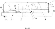
- the opening may be embodied between the measurement cell body and the substrate, and in particular between the frame and the substrate.
- the opening may be closed by the gas permeable membrane.
- a ring-shaped membrane may be arranged onto the substrate, and the ring-shaped frame may be deposited onto the membrane.
- the frame may contain integral clips in order to mount the frame to the substrate.
- Such one or more clips may engage on the back side of the substrate for fixing the frame to the substrate with a sufficient force to provide a sealing.
- Appropriate access to the membrane from the surroundings is provided. Accordingly, the membrane at the same time seals the measurement volume against particles and liquids, and provides for a lateral diffusion of the gas from the outside through the membrane.
- the measurement cell body is mounted to the substrate by means of a snap fit.
- the measurement cell body comprises one or more snap arms and the substrate comprises one or more corresponding holes for the one or more snap arms to reach through.
- the snap fit is designed to mount the measurement cell body acoustically tight to the substrate.
- a footprint of the substrate and a footprint of the measurement cell body match by a tolerance of at most 10% for each dimension defining the planar extension thereof.
- the substrate and a projection of the measurement cell body onto the substrate may match more or less.
- a first cap is mounted on the front side of the substrate and a second cap is mounted on top of the first cap.
- a ceiling of the first cap represents or includes the reflective shield.
- the second cap and the flange of the first cap in combination represent the measurement cell body.
- the opening for the gas to enter preferably is arranged in the second volume.
- the measurement cell body may be mounted to the substrate by means of a snap fit.
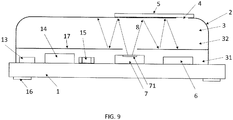
- the substrate comprises the opening.
- the gas enters the first volume through the substrate, and the second volume through the aperture in the reflective shield.
- the membrane preferably is attached to the front side of the substrate. This arrangement of the membrane improves the assembly of the substrate.
- the electrical components to be arranged on the front side of the substrate and the membrane may preferably be assembled onto the substrate in a common step, such as a surface mounting step. This reduces the number of assembly steps for manufacturing the device.
- the membrane may be soldered by a solder applied to an edge of the membrane which enables reflow soldering. In this arrangement of the membrane inside the first volume, the membrane itself is protected from mechanical impact and dust and dirt.
- the opening in the substrate and the aperture in the reflective shield are offset from each other in the lateral dimension. This already results from the preference that the radiation source is arranged on the substrate in alignment with the aperture such that the location of the radiation source on the substrate cannot be used for the opening in the substrate and the membrane covering the opening. This is beneficial also for the reason, that the membrane typically is of low reflectivity and as such does not form part of the second volume.
- a photoacoustic gas sensor device for determining a value indicative of a presence or a concentration of a component in a gas.
- the photoacoustic gas sensor device of this aspect comprises: A substrate and a measurement cell body.
- the substrate and the measurement cell body define a measurement cell enclosing a measurement volume.
- An electromagnetic radiation source is provided for emitting electromagnetic radiation in the measurement volume.
- a pressure transducer is provided for measuring a sound wave generated by the component in response to an absorption of electromagnetic radiation by the component.
- the electromagnetic radiation source and the pressure transducer are arranged on the front side of the substrate and in the measurement volume.
- the substrate comprises an opening for a gas to enter the measurement volume.
- a photoacoustic gas sensor device for determining a value indicative of a presence or a concentration of a component in a gas.
- the photoacoustic gas sensor device of this aspect comprises: A substrate and a measurement cell body.
- the substrate and the measurement cell body define a measurement cell enclosing a measurement volume.
- An electromagnetic radiation source is provided for emitting electromagnetic radiation in the measurement volume.
- a pressure transducer is provided for measuring a sound wave generated by the component in response to an absorption of electromagnetic radiation by the component.
- the electromagnetic radiation source and the pressure transducer are arranged on the front side of the substrate and in the measurement volume.
- an opening for a gas to enter the measurement volume is formed by a gap between the measurement cell body and the substrate.
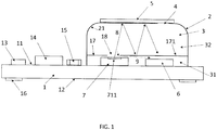
- Fig. 1 shows a schematic cut view of a photoacoustic gas sensor device according to an embodiment of the present invention.
- the device comprises a substrate 1, e.g. a printed circuit board (PCB), with a front side 11 and a back side 12 opposite the front side 11.
- a measurement cell body 2 is mounted on the front side 11 of the substrate 1, which substrate 1 and measurement cell body 2 together form a measurement cell enclosing a measurement volume 3.
- the measurement cell has an opening 4 to allow an exchange of gas between the measurement volume 3 and surroundings of the device.
- the opening 4 is located in the measurement cell body 2.
- the opening 4 is preferably covered by a membrane 5 which is gas permeable to allow for a gas exchange such that a concentration of the component of interest in the gas is similar as in the surroundings.
- a pressure transducer 6 such as a MEMS microphone or a pressure sensor, and an electromagnetic radiation source 7, which in this example is an infrared source, are both located on the front side 11 of the substrate inside the measurement cell.
- the electromagnetic radiation source includes an active area 711 emitting the electromagnetic radiation, i.e. the infrared radiation in this example, indicated by arrows 8.
- the infrared source emits infrared radiation of the band, wherein the intensity of the infrared radiation is modulated as described above.
- the infrared radiation is selectively absorbed by molecules of the gas component of interest.
- a reflective shield 17 is provided in the measurement cell.
- the reflective shield 17 presently extends in a plane parallel to a planar extension of the substrate 1.
- the reflective shield 17 is attached to or formed integrally with the measurement cell body 2.
- the reflective shield 17 divides the measurement volume 3 into a first volume 31 between the substrate 1 and the shield 17, and a second volume 32 between the shield 17 and the measurement cell body 2.
- the reflective shield 17 comprises an aperture 18 which presently is aligned with the infrared source 7, such that infrared radiation 8 can emit from the infrared source 7 through the aperture 18 into the second volume 32.
- a surface 171 of the shield 17 facing the second volume 32 is made of a material reflecting the electromagnetic radiation emitted by the electromagnetic radiation source 7. This is indicated by the various arrows representing the electromagnetic radiation 8 reflected in the second volume 32 after being emitted from the infrared source 7.
- a ratio of infrared radiation 8 absorbed is increased by increasing a mean optical path length of the infrared radiation 8 within the measurement volume 3. This is achieved by a material of at least the inner surface 21 of the measurement cell body 2 being chosen to be reflective.
- the reflective coating may be made from a metal such as gold, aluminum, nickel, copper. In this way, the overall reflectivity inside the second volume 32 is increased, which leads to more accurate measurements of the concentration of the component.
- the photoacoustic effect comes into play: Molecules of the gas component of interest, e.g. CO 2 , absorb the electromagnetic radiation in the second volume 32 leading to the generation of heat and hence an increase of pressure.
- a modulation of pressure may be achieved.
- Such pressure modulation or pressure variations may be measured by the pressure transducer 6.
- the aperture 18 in the reflective shield 17 allows such sound waves generated in the second volume 32 to reach into the first volume 31 and hence to reach the pressure transducer 6.
- the sound waves are indicated by reference numeral 9 in Fig. 1 .
- the second volume 32 in which the absorption and sound wave generation predominantly takes place, is communicatively coupled to the first volume 31 and the pressure transducer 6. Accordingly, in the present example, not only the electromagnetic radiation enters the second volume 32 through the aperture 18, but also the sound waves propagate from the second volume 32 into the first volume 31 to the pressure transducer 6.
- An integrated circuit 14 is arranged on the front side 11 of the substrate 1, which integrated circuit 14 may e.g. be an ASIC.
- the integrated circuit 14 is located outside the measurement cell; in a different embodiment, however, it may as well be located inside the measurement cell.
- the integrated circuit 14 is configured to control the electromagnetic radiation source 7, e.g. by imposing an intensity modulation on e.g. the infrared radiation emitted with a modulation frequency.
- the modulation frequency may be within the audible spectrum, e.g. between 20 Hz and 20 kHz, or it may be up to 100 kHz, or it may even be down to 5 Hz.
- the integrated circuit 14 is further configured to receive measurement values from the pressure transducer 6, as well as for determining a value of the gas component concentration from those measurement values, e.g. by using a predefined or a resettable calibration function linking the measurement values to concentration value of the gas component.
- the value of the gas component concentration may be output via a digital interface, e.g. an I2C interface, as may be values of one or more other transducers if any.
- another transducer 13 is arranged on the front side 11 of the substrate 1.
- the other transducer 13 is located outside the measurement cell; in a different embodiment, however, it may as well be located inside the measurement cell.
- Such other transducer 13 advantageously is one or more of the following: a temperature sensor, a humidity sensor, a combined temperature/humidity sensor, a pressure sensor, in particular a barometric pressure sensor, another microphone, another gas sensor, e.g. of metal oxide type or of electrochemical type.
- a gas concentration value may be compensated, e.g. for effects of temperature and/or humidity, e.g. by the integrated circuit 14. Hence, effects of ambient conditions on the measurement of the component can be reduced or eliminated.
- Further electrical components 15 may be arranged on the front side 11 of the substrate 1, preferably outside the measurement cell. Such further electrical components 15 may include passive components or auxiliary electronics, e.g. capacitors and resistors, as required.
- LGA land grid array
- the component to be measured is CO 2 .
- CO 2 measurements in the range between 0 and 10'000 ppm, or between 0 and 40'000 ppm, or between 0 and 60'000 ppm CO 2 are possible.
- the proposed photoacoustic gas sensor device may be built with a small form factor, such that it has an overall size of e.g. 1 x 1 x 0.7 cm 3 .
- a small form factor such that it has an overall size of e.g. 1 x 1 x 0.7 cm 3 .
- it is significantly smaller and also cheaper to manufacture than conventional photoacoustic or NDIR-based gas sensors.
- the electromagnetic radiation source 7 is embodied different from the one used in Fig. 1 .
- the electromagnetic radiation source 7 of Fig. 2 comprises an emitter 71 packaged into a package 73, and an optical bandpass filter 72 on top of the package 73.
- the package 73 has an access opening 731 for radiation emitted by the emitter 71 to reach the second volume 32.
- the emitter 71 may be a broadband infrared emitter, e.g. emitting radiation over the entire infrared spectrum.
- the optical bandpass filter 72 allows to exclusively pass radiation of a band that is set according to the gas component of interest.
- the band is for instance centered around 4.3 pm, and has a typical band width of 0.5 ⁇ m, or smaller, e.g. 0.2 ⁇ m or 0.1 ⁇ m, such that a measured value is actually selective on CO 2 .
- the optical aperture 18 and a further optical aperture represented by the properly designed access opening 731 may in combination prevent radiation of different bands to enter the second volume 32.
- the optical bandpass filter 72 is in contact with the reflective shield 17, e.g. via an O-ring or other sealing means. While such arrangement may be beneficial for several purposes such as thermal shielding etc., the acoustic coupling between the second volume 32 and the first volume 31, and the pressure transducer 6 respectively now no longer can be granted through the aperture 18 in the reflective shield 17. For this reason, gaps are provided between the reflective shield and the substrate 1 or the measurement cell body 2, for acoustically coupling the second volume 32 to the pressure transducer 6. Such gaps may better be seen from subsequent diagram 4c).
- the reflective shield 17 is not attached nor mounted to the measurement cell body 2, but instead is directly mounted onto the substrate 1, i.e. on the front side 11 of the substrate 1 such as all the other electrical components.
- the reflective shield 17 not only provides a planar extension, but also provides for one or more legs referred to by 172.
- the reflective shield 17 and its legs 172 are made integrally, and, e.g. the legs 172 are bent in order to serve as support.
- the reflective shield 17 including the legs 172 are spaced apart from the measurement cell body 2, i.e. a gap is provided between the legs 172 of the reflective shield 17 and the measurement cell body 2 as is shown in Fig.
- the reflective shield 17 including its legs 172 is made from metal, the reflective shield 172 not only serves as reflecting element, but also as protection against electrostatic discharge.
- the legs 172 is electrically connected to a ground contact 10 on the front side 11 of the substrate 1.
- This ground contact 10 may, via additional wiring on or in the substrate 1, be electrically connected to one of the contact pads 16, and serve as a ground connection for the entire photoacoustic sensor device.
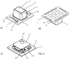
- Figure 4 illustrates another embodiment of a photoacoustic gas sensor according to the present invention in two perspective views from top in a), and from bottom in b).
- diagram c) shows the photoacoustic gas sensor in a perspective view from top without the measurement cell body 2.
- the photoacoustic gas sensor of this embodiment may be considered as a variation of the photoacoustic gas sensor of the embodiment of Fig. 3 .
- the components 13, 14 and 15 are assembled at different locations on the substrate 1 outside the measurement cell. However, inside the measurement cell, as can be seen from the open cut view in Fig.
- the shield 17 again comprises legs 172 for mounting on the substrate 1.
- one of the mounting pads on the front side 11 of the substrate 1 serves as ground contact 10.
- One of the legs of the shield is electrically connected, e.g. soldered to the ground contact 10, for ESD purposes as laid out above.
- the cut open photoacoustic gas sensor from Fig. 4c ) is slightly different from the embodiment shown in Fig. 4a) and 4b ) in that the components 13, 14 and 15 previously arranged outside the measurement cell are now arranged under the reflective shield 17 inside the measurement cell to be built by mounting the measurement cell body 2 onto the substrate 1.
- the reflective shield 17 now is formed integrally with the measurement cell body 2.
- the measurement cell body 2 comprises a frame 22, and a lid 21 acting as a cover.
- the opening 4 now is provided in the lid 21, and the membrane 5 is attached to a top side of the lid 21 facing the surroundings.
- the frame 22, the lid 21 and the reflective shield 17 may all be made from the reflective material, e.g. from metal.
- one or more of the frame 22, the lid 21 and the reflective shield 17 may comprise a plastic core, and a reflective coating where desired.
- the electromagnetic radiation 8 enters the second volume 32 through the aperture 18 in the reflective shield 17.
- Fig. 6 resembles the embodiment of Fig. 5 .
- the reflective shield 17 is formed integrally with the measurement cell body 2, which additionally comprises a frame 22.
- a lid 21 manufactured separate from the frame 22 but attached thereto acts as a cover co-defining the second volume 32.
- the frame 22 now includes an overhang 221, also referred to as bulge.
- the overhang 221 By means of the overhang 221, a compartment 19 is generated between the frame 22 and the substrate 1, which compartment is open to the left hand side.
- the compartment 19 is not part of the measurement volume 3 but is located outside.
- electrical components such as the other transducer 13 arranged on the front side 11 of the substrate 1 in the compartment 19 are protected by the overhang 221, and thus may be less exposed not only to mechanical impact but also to moisture, dirt etc.
- the measurement cell body 2 and the reflective shield 17 are embodied in a different setup.
- a first cap 23 is mounted on the front side 11 of the substrate 1, and a second cap 24 is mounted on top of the first cap 23.
- a ceiling 213 of the first cap 23 serves as reflective shield 17, while side walls of the first cap and the second cap 24 in combination contribute to the measurement cell body 2.
- the opening is arranged in the second cap 24, while the opening is arranged in the ceiling 231 of the first cap 23.
- the embodiment of Fig. 8 differs from the embodiment of Fig. 5 in that all electrical components are arranged inside the measurement volume 3, and specifically are commonly arranged in the first volume 31 on the front side 11 of the substrate 1.
- This may include, in addition to the electromagnetic radiation source 7 and the pressure transducer 6 as follows:
- this configuration may increase the footprint of the sensor, while on the other hand all electrical components are now protected by the reflective shield 17 and the measurement cell body 2.
- the electrical components may in addition benefit from other functions performed by the reflective shield 17, such as electrostatic discharge protection or thermal management.
- the embodiment of Fig. 8 differs from the embodiment of Fig. 5 in that the opening 4 now is provided between the substrate 1 and the measurement cell body 2.
- a horizontal gap is generated between the front side 11 of the substrate 1 and a bottom surface of the frame.
- This gap preferably takes the shape of a ring around the measurement volume 3, and is filled by e.g. a ring of gas permeable membrane material.
- the gas to be measured enters the measurement volume 3 laterally through the opening 4 between the measurement cell body 2 and the substrate 1, and diffuses from the first volume 31 through the aperture 18 into the second volume 32 where it meets the electromagnetic radiation 8. This process is indicated in Fig.
- the lid 21 is understood to seal the measurement volume 3 from the top.
- the footprint of the substrate 1 matches the footprint of the measurement cell body 2 such that snap fits 25 can be used for easily attaching the measurement cell body 2 to the substrate 1.
- the embodiment of Fig. 9 differs from the embodiment of Fig. 1 in that all electrical components are arranged inside the measurement volume 3, and specifically are commonly arranged in the first volume 31 on the front side 11 of the substrate 1.
- This may include, in addition to the electromagnetic radiation source 7 and the pressure transducer 6 as follows:
- this configuration is advantageous in that all electrical components are now protected by the reflective shield 17 and the measurement cell body 2.
- the electrical components may in addition benefit from other functions performed by the reflective shield 17, such as electrostatic discharge protection or thermal management.
- the embodiment of Figure 10 resembles the embodiment of Fig. 9 with all electrical components being commonly arranged within the measurement volume 3, and specifically within the first volume 31.
- the opening 4 in the embodiment of Fig. 9 is arranged in the measurement cell body 2, and specifically in the portion of the measurement cell body 2 defining the second volume 32
- the opening 4 of the embodiment of Fig. 10 now is arranged in the substrate 1, in form of a through-hole in the substrate 1.
- the gas to be measured enters the measurement volume 3 through the opening 4 in the substrate 1, and diffuses from the first volume 31 through the aperture 18 into the second volume 32 where it meets the electromagnetic radiation 8.
- the gas permeable membrane 5 now is attached to the substrate 1, and preferably is attached to the front side 11 of the substrate 1 facing the first volume 31.
- the lid 21 is understood to seal the measurement volume 3 from the top.
Landscapes
- Physics & Mathematics (AREA)
- Health & Medical Sciences (AREA)
- Life Sciences & Earth Sciences (AREA)
- Chemical & Material Sciences (AREA)
- Analytical Chemistry (AREA)
- Biochemistry (AREA)
- General Health & Medical Sciences (AREA)
- General Physics & Mathematics (AREA)
- Immunology (AREA)
- Pathology (AREA)
- Acoustics & Sound (AREA)
- Optics & Photonics (AREA)
- Investigating Or Analysing Materials By Optical Means (AREA)
Abstract
Description
- The present invention relates to a photoacoustic gas sensor device which is configured to determine a value indicative of a presence or a concentration of a component, in particular of CO2, in a gas.
- Photoacoustic gas sensors rely on the physical effect that e.g. infrared radiation is absorbed by molecules of a component of interest in a gas, e.g. CO2, thereby transferring the molecules to an excited state. Subsequently heat is generated due to non-radiative decay of the excited state, e.g. by collisions of the molecules, which leads to an increase of pressure. Through modulating the infrared radiation to be absorbed with a modulation frequency, the pressure varies at the modulation frequency. Such pressure variation may be measured by a pressure transducer. The concentration of the component is proportional to an amplitude of the pressure variation.
- In early photoacoustic gas sensors, a light source required for emitting the infrared radiation is located outside a measurement cell in which the photoacoustic effect is produced. The resulting gas sensor constitutes a bulky arrangement.
- In more recent photoacoustic gas sensors the light source and the pressure transducer are arranged inside the measurement cell. However, such measurement cell still is large in size due to a long optical path length required for sufficient absorption of infrared radiation by molecules of the component. Moreover, a complex three-dimensional assembly of measurement cell, infrared source and pressure transducer is required. In addition, the infrared source and the pressure transducer may represent electrical components in the measurement cell, which do not promote reflection of the emitted light.
- It is hence an object of the present invention to provide a photoacoustic gas sensor device showing a good reflectivity for the radiation emitted, and preferably being small in size.
- The object is achieved by a photoacoustic gas sensor device according to a first aspect of the present invention as claimed in
claim 1. The photoacoustic gas sensor device for determining a value indicative of a presence or a concentration of a component in a gas comprises a substrate and a measurement cell body arranged on a front side of the substrate. The substrate and the measurement cell body define a measurement cell enclosing a measurement volume. The measurement cell comprises an opening for a gas entering the measurement cell. In one embodiment, the opening allows a gas exchange between the measurement volume and surroundings of the measurement cell. The device further comprises an electromagnetic radiation source for emitting electromagnetic radiation, and a pressure transducer for measuring a sound wave generated by the component in response to an absorption of electromagnetic radiation by the component. The electromagnetic radiation source and the pressure transducer are arranged on the front side of the substrate and in the measurement volume. - A reflective shield is provided dividing the measurement volume into a first volume and a second volume. The pressure transducer as well as the electromagnetic radiation source are arranged in the first volume on the front side of the substrate. It is understood that the first volume is a volume common to the electromagnetic radiation source and the pressure transducer, i.e. the electromagnetic radiation source and the pressure transducer share the same space, i.e. a common space. Specifically, there is no barrier in the first volume between the pressure transducer and the electromagnetic radiation source. Although - as will be shown in more detail below - the actual photoacoustic conversion preferably takes place in the second volume, a combination of the first and the second volume still is legitimate to refer to as measurement volume given that the pressure transducer as measuring entity is located in the first volume. It is understood, that the measurement volume may be divided in more than two sub-volumes. However, the measurement volume is divided in at least the first and the second volume. It is further understood, that the side of the substrate both the electromagnetic radiation source and the pressure transducer are arranged on and mounted to is referred to as front side of the substrate. A side of the substrate opposite to the front side is referred to as back side.
- The reflective shield comprises an aperture through which electromagnetic radiation generated by the electromagnetic radiation source is transmitted into the second volume, which aperture preferably is a single aperture. Hence, dividing the measurement volume into a first and a second volume does not imply two volumes sealed from each other. In contrast, the second volume is communicatively coupled to the first volume and specifically to the pressure transducer arranged therein. This enables the pressure transducer to detect sound variations caused by the absorption of the electromagnetic radiation by the components of interest in the first volume. Hence, the communicative coupling preferably is an acoustic coupling, and preferably includes that pressure changes in the second volume are detectable by the pressure transducer arranged in the first volume. The acoustic coupling may in one embodiment be effected by the single aperture in the reflective shield.
- At least a portion of a surface of the reflective shield facing the second volume is made of a material reflecting electromagnetic radiation, and in particular reflecting the electromagnetic radiation of the specific wavelength or wavelength band emitted by the electromagnetic radiation source. The wavelength or wavelength band of the radiation emitted preferably coincides or includes the wavelength or wavelength band the component in the gas is prone to absorb.
- For the above purpose of providing good reflectivity characteristics in the second volume, it is preferred that at least the major portion of the surface of the reflective shield facing the second volume is made of the reflective material, i.e. at least 50% of this surface. However, with the intent to further increase the reflectivity in the second volume, it is even more preferred that the entire surface of the reflective shield facing the second volume is made of the reflective material. In one alternative, the entire reflective shield is made of the reflective material, such that not only the surface facing the second volume but also the surface facing the first volume is made from the reflective material. In a different alternative, the reflective shield is made from at least two different materials, e.g. a core of the reflective shield is made of a first non- or low-reflective material, e.g. plastics, and a coating deposited on the core is made of a second material which is the reflective material. The coating may only be applied to the surface facing the second volume, or the coating may also be applied to the other surface of the reflective shield facing the first volume.
- Preferably, it is intended to maximize surfaces defining the second volume with reflective material. Accordingly, at least a portion of an inner surface of the measurement cell body facing the second volume is made of the same reflective material the reflective shield is made of, or is made from a different reflective material. Even more preferably, at least a major portion of the inner surface of the measurement cell body facing the second volume is made of the or another reflective material, i.e. at least 50% of this inner surface. However, with the intent to further increase the reflectivity in the second volume, it is even more preferred that the entire inner surface of the measurement cell body facing the second volume, and in another variant the entire inner surface of the measurement cell body is made of the reflective material. I.e., a portion of or the entire inner surface preferably is made from the reflective material, again, either by way of a reflective coating applied to a core of the measurement cell body, or by the measurement cell body being made of the reflective material. In the latter embodiment, the measurement cell body may be made from sheet metal, e.g. by deep drawing. Sheet metal has the advantages of being mechanically stable even at low thickness, and of showing a high reflectivity for electromagnetic radiation even without any further coating. In the earlier embodiment, a core of the measurement cell body is made a non- or low-reflecting material, e.g. plastics, e.g. by injection molding, and a reflective coating is applied onto the inner surface.
- Generally, the or a reflective material preferably is metal, or is a metal-filled polymer, or is a metallized or mirrored glass, or is another material with a high reflectivity, in particular for the wavelength of the radiation emitted. The reflective material e.g. may be one or more of gold, aluminum, nickel, or copper. These materials may in particular be used in case of a reflective coating is applied to a core.
- As to the degree of reflectivity of the reflective material as used, it is preferred that surfaces of reflective material and / or surfaces defining the second volume have a reflectivity of more than 70%, preferably more than 80%, and more preferably more than 90%, each preferably in the band. In an embodiment, a ratio of inner surfaces of the second volume with a reflectivity of above 70% to inner surfaces of the second volume with a reflectivity of below 70% is above 20, preferably above 50, and more preferably above 100.
- Accordingly, the second volume is designed to provide characteristics that best enable a reflection of the emitted radiation. While in conventional photoacoustic sensors the pressure transducer and the electromagnetic radiation source may be arranged in the measurement volume, such components often provide non- or bad reflecting surfaces while on the other hand these surfaces may constitute a non-negligible amount of the total surface defining the measurement volume. In the present approach, the electrical components including the pressure transducer and the electromagnetic radiation source are physically separated from the second volume which predominantly serves as space for enabling the photoacoustic conversion. Hence, any non-reflecting surfaces of the electrical components no longer affect the pathways of the radiation, and hence do not disturb the photoacoustic reactions or lower the sensitivity of the measurement signal. Furthermore, a high reflectivity of the inner surfaces of the measurement cell reduces an offset of the pressure signal, which is generated by the photoacoustic effect occurring in solid matter, e.g. on the surface of the measurement cell body.
- Now, the second volume as part of the measurement volume in which the photoacoustic reactions preferably take place is separated from the first volume which is designed for accepting the electrical components to be placed within the measurement volume.
- However, the first volume and the second volume are not separated in a way that the first volume is sealed from the second volume. Instead, the electromagnetic radiation generated by the corresponding source located in the first volume enters the second volume by an aperture in the reflective shield. Preferably, the electromagnetic radiation source is aligned with the aperture such that the radiation generated by the source enters through the aperture in the second volume. Once the electromagnetic radiation having entered in the second volume, the one or more reflective surfaces defining the second volume reflect the electromagnetic radiation. This enables long pathways of the reflected light signals. Long pathways in turn provoke best chances to make the electromagnetic radiation react with the molecules of the component desired to be detected in the gas resident in the second volume. Signal amplitude and signal to noise ratio supplied by the pressure transducer are improved. Accordingly, the reflective shield is applied and arranged to generate a separate volume, i.e. the second volume, which shows enhanced reflectivity. This second volume may in one embodiment be defined only by one surface of the reflective shield and an inner surface of the measurement cell body, and in particular may not contain any electrical components with non- or bad-reflecting properties.
- In the second volume, the photoacoustic effect occurs: Molecules of a gas component of interest, e.g. CO2, absorb electromagnetic radiation, in this example infrared radiation. The absorption leads to a generation of heat due to non-radiative decay, e.g. by collisions between the molecules of the gas component of and / or by collisions of the molecules of the gas component with different molecules, which in turn leads to an increase of pressure. By modulating an intensity of the electromagnetic radiation with a modulation frequency, a modulation of pressure may be achieved. Such pressure modulation represented by pressure variations, i.e. sound waves, may be measured by the pressure transducer arranged in the first volume. The value indicative of a presence or a concentration of the component, i.e. the component's concentration, may then be determined dependent on an amplitude of the pressure variations. The amplitude may be assumed to be proportional to an amount of electromagnetic radiation absorbed by the component, and hence proportional to the component's concentration in the gas if all other factors, e.g. a mean optical path length in the measurement volume, stay equal.
- Hence it is preferred that a large fraction of the electromagnetic radiation emitted by the electromagnetic radiation source is actually absorbed by the component, and preferably selectively absorbed only by the component of interest, and neither by other components of the gas nor by components of the device.
- Moreover it is preferred that the pressure transducer measures the pressure variations, i.e. sound waves, at the modulation frequency caused by the photoacoustic effect in the component of interest, but not other sounds, e.g. sounds from the surroundings. The pressure transducer in the first volume is acoustically coupled to the second volume, i.e. a pressure equilibrium is generated between the first volume and the second volume at least for mid- and long-term pressure variations. Instead, short-term pressure variations arising from the photoacoustic effect, e.g. in time scales << than the inverse of the modulation frequency, are desired to be transmitted from the second volume into the first volume to be detected by the pressure transducer. In one embodiment, the acoustic coupling is achieved by the aperture in the reflective shield. This aperture then serves for both the acoustic coupling of the second volume to the first volume, and the optical coupling of the first volume to the second volume. In case the aperture in the reflective shield is the exclusive gate for a pressure compensation between the first volume and the second volume, it is preferred that the shield is arranged at a distance > 0 from the electromagnetic radiation source. Accordingly, the reflective shield is not sealed against the electromagnetic radiation source by means of the aperture. For this reason static pressure is balanced between the first and the second volume and gas may exchange between the first and second volume, while changes in pressure propagate through the aperture from the second volume into the first volume. The distance between the reflective shield and the electromagnetic radiation source preferably is between 10 um and 1 mm, and more preferably between 50 um und 200 um. Preferably, a diameter of the aperture in the reflective shield is between 100 um and 5 mm.
- In addition to the aperture in the reflective shield, or alternatively, one or more additional apertures may be provided in the reflective shield for acoustic coupling. In addition to or instead of the one or more apertures, one or more gaps may be provided between the reflective shield and the measurement cell body, and / or between the reflective shield and the substrate in case the reflective shield is mounted on the substrate. In particular in the case of gaps, the reflective shield is embodiment as element separate from the measurement cell body. The gaps may then be designed on purpose, e.g. in the reflective shield, or may be generated by using manufacturing tolerances. For example, a gap between the measurement cell body and the reflective shield, which may be include multiple individual gaps or a single gap surrounding the reflective shield, may in one embodiment have a width between 10 um und 1 mm, or more preferably between 50 um und 200 um. Hence, a design and / or an arrangement of the optical reflective shield by no means lead to an acoustic shielding between the second and the first volume. Instead, pressure variations can be detected by the pressure transducer.
- The provision of the second volume contributes to a longer mean optical path length of the electromagnetic radiation within the second volume. In this way, the mean optical path length within the second volume, which is a zig-zag path owed to the reflections, may be increased to > 1 cm, preferably > 3 cm, more preferably > 5 cm. This in turn facilitates the measurement cell to be small, in particular smaller than conventional photoacoustic gas sensors having a linear optical path length. In particular, dimensions of the measurement cell may be smaller than 2 x 2 x 2 cm3, preferably smaller than 1 x 1 x 1 cm3. The entire photoacoustic gas sensor device may have a size of e.g. 1 x 1 x 0.7 cm3. Despite the small size of the measurement cell, the mean optical path length is comparable, or even larger, than in many conventional photoacoustic gas detectors, and / or in conventional NDIR sensors.
- Further advantages of the present invention include: The device is less prone to mechanical instabilities than conventional gas sensors, and may be built very stable. The values of the concentration of the component of interest are offset-free due to the underlying measurement principle of the photoacoustic effect, so only one device is needed for accurate measurements. Furthermore, a high reflectivity of the inner surfaces of the measurement cell reduces an offset of the pressure signal, which is generated by the photoacoustic effect occurring in solid matter, e.g. on the surface of the measurement cell body.
- Specifically, the pressure transducer may be a microphone, in particular a microphone that is sensitive to only a certain range of frequencies around the modulation frequency. In one embodiment, the microphone is a bottom port microphone, a port of which microphone faces the substrate. On the one hand, this requires an opening, e.g. a lateral opening, between the microphone and the substrate such that the second volume and the bottom port of the microphone are communicatively coupled. Of course, the same applies to conventional microphones with a port facing the reflective shield. In a different embodiment, the pressure transducer is a pressure sensor.
- In a preferred embodiment, the electromagnetic radiation is infrared radiation. This means that the electromagnetic radiation source is an infrared radiation source configured to emit infrared radiation. Infrared radiation preferably is defined as radiation having a wavelength in a range between 700 nm and 1 mm. In another embodiment, the electromagnetic radiation source is a source for emitting radiation of a wavelength in a range between 100 nm and 700 nm. The electromagnetic radiation source may in one embodiment be a heater, in another embodiment be a laser, in a further embodiment be an LED. The heater may also be considered as a broadband radiation source, while the laser and the LED may be considered a narrow band radiation source.
- In a preferred embodiment, the electromagnetic radiation source comprises an emitter having an active area configured to emit the radiation in response to an excitation. As to the aperture in the shield, it is preferred that its size is adapted to a size of the active area. Ideally, all beams of the desired wavelength or band emitted by the active area would make it through the aperture. However, in case of misled light beams, it is preferred that the aperture in the reflective shield serves as an optical aperture and prevents undesired light beams from entering the second volume. For this purpose, a distance between the reflective shield and the electromagnetic radiation source is preferred between 10 um and 1 mm, and more preferably between 50 um und 200 um. Preferably, a diameter of the aperture in the reflective shield is between 100 um and 5 mm.
- Preferably, the electromagnetic radiation emitted by the electromagnetic radiation source is only emitted in a band matching an absorption peak of the gas component of interest. A band is considered a subrange of the electromagnetic spectrum, preferably symmetrically around a wavelength representing the absorption peak, with a max / min band limit of +/- 15% of the wavelength representing absorption peak value.
- In an embodiment, the photoacoustic gas sensor device is used as a CO2 sensor. In that case the band of infrared radiation is centered around a wavelength of 4.3 µm. Preferably the band has a full width at half maximum of below 0.5 µm, which may be understood as a narrow band. A narrowband source may e.g. comprise a meta-surface resonator, and may be embodied as an LED, for example.
- In another embodiment, the electromagnetic radiation source comprises a broadband emitter covered by a wavelength-selective bandpass filter configured to filter out electromagnetic radiation outside the band. The broadband emitter is defined as emitting radiation of a wide spectrum, such as across the entire infrared spectrum, or e.g. between 0.8 µm and 10 µm. Such broadband emitter may be a conventional infrared emitter with a heater.
- In one embodiment, the emitter comprises a semiconductor chip embodying a hotplate, i.e. a thinned area of low thermal conductivity. On the hotplate, a light emitting structure is arranged and serves as active area. In a different embodiment, the hotplate in form of a thin membrane may represent the active area itself and radiate, e.g. in response to being heated. The hotplate may contain electrically conducting structures, collectively referred to as heater for heating the hotplate. In one embodiment, the active area of the hotplate may additionally comprise a coating or a layered stack for shaping the emissivity of the desired radiation, i.e. in particular of increasing the emissivity of radiation with the desired wavelengths or bands, and / or by decreasing or blocking the emissivity of radiation of wavelengths outside the band. In one embodiment, the hotplate may additionally comprise a temperature sensor used in a control of the temperature of the hotplate to a desired value.
- The emitter preferably is packaged, and the package, e.g. a mold compound, has an access opening for allowing the emitter to emit the radiation. The access opening in the package may serve at the same time as optical aperture. Given that the package may exceed the emitter in height, the reflective shield, even if in contact with the package, is spaced from the active area of the emitter. This spacing preferably is between 20% and 200%, and preferably between 50 und 150% of the diameter of the active area of the emitter. In terms of improving heating efficiency, a distance between the active area of the emitter and a top surface of the package at the same time defining a top end of the access opening is preferred to be at least a fifth, preferably a third, preferably half of a diameter of the access opening.
- In one embodiment, before packaging the emitter preferably is placed on a die pad of a carrier such as a leadframe. Heater contacts and / or other electrical contacts of the emitter are electrically connected to the carrier, e.g. by means of wire bonding. The die pad and the hot plate structure of the emitter may define a closed cavity in between, which in particular is an acoustically closed cavity. In terms of improving heating efficiency, a distance between the hot plate of the emitter and the die pad is preferred to be at least a fifth, preferably a third, preferably half of a diameter of the cavity. The leadframe and the emitter are packaged together in a common packaging step, in which the access opening is manufactured by means of a suitably shaped mold. The packaged emitter may then be placed and SMD mounted on the substrate.
- In case of the emitter being a broadband emitter, the emitter preferably is covered by an optical bandpass filter. The optical bandpass filter may be arranged on the package for the emitter. For mounting the optical bandpass filter to the package, the package preferably contains a step for accepting the bandpass filter. The bandpass filter may be applied onto the step and be attached to the package, e.g. by gluing. The optical bandpass filter e.g. may be a dielectric filter, or a meta-material filter, or a CMOS absorption layer, such that in one embodiment only radiation of the desired band is emitted into the second volume.
- The aperture in the reflective shield may not only serve for allowing radiation to enter the second volume, but may also serve as an optical aperture and prevent undesired radiation from entering the second volume. Undesired radiation may include light beams with wavelengths outside the desired band given that such radiation will not be absorbed by the target components in the gas. In particular, such undesired light beams may be generated in electromagnetic radiation sources comprising an emitter with a wide emergent angle.
- For such shielding purposes, it is preferred that a diameter of the aperture in the reflective shield is between 100% and 400% of the diameter of the active area of the emitter, and more preferably between 200% and 300%. In a preferred embodiment, these dimensions are assumed in combination with a spacing between the reflective shield and the active area of the emitter of between 20% and 200% of the diameter of the active area, and more preferably between 50 und 150%. Such dimensioning of the diameter of the aperture of the reflective shield may also be applicable in combination with an electromagnetic radiation source absent an optical bandpass filter.
- Alternatively or in addition, the diameter of the aperture of the reflective shield may also be dimensioned dependent from the emission profile of the emitter used. For example, a collimated emitter, such as a laser, in particular such as a VCSEL = Vertical-cavity surface-emitting laser will by nature show a narrow emergent angle, while a Lambertian emitter such as an infrared emitter comprising a heater shows a wide emergent angle in all 3D directions. Accordingly, for the collimated emitter, an aperture in the reflective shield preferably shows a diameter smaller than a diameter of an aperture in the reflective shield when applied in combination with a Lambertian emitter.
- In case of a broadband emitter operated in combination with an optical bandpass filter, the radiation generated e.g. by an emitter with a wide emission profile may contain beams striking the optical bandpass filter with an incident angle deviating from the normal. In such scenario, the optical bandpass filter transmits a spectrum deviating from the desired band and dependent from the incident angle of the radiation, which spectrum in particular contains radiation outside the desired band. In such scenario, the access opening of the package on which the optical bandpass filter is mounted may be used as optical aperture, which preferably serves for limiting the incident angle of radiation into the optical bandpass filter. For such shielding purposes, a diameter of the access opening in the package is between 1.5 and 3 times the diameter of the active area of the emitter. In case of radiation of undesired wavelengths still reaching through the optical bandpass filter - e.g. emitted from sides of the optical bandpass filter owing to internal reflections - it is preferred that the reflective shield is arranged to cover the edges of the optical band pass filter either with or without a distance from the optical band pass filter. Alternatively or in addition, a diameter of the aperture in the reflective shield preferably is between 1 and 2.5 times the diameter of the access opening in the package. Hence, the diameters of the aperture in the reflective shield and the access opening of the package are selected in relation to each other and preferably also in relation to the diameter of the active area such that radiation emitted by the emitter with an angle of more than 60°, and preferably more than 45° relative to the normal is blocked by these apertures. In the above embodiments, the reflective shield preferably is arranged at a distance from a top surface of the optical bandpass filter between 0 um und 200 um.
- Preferably, a thickness of the reflective shield is between 30 µm and 1 mm, in particular between 50 µm and 200 µm. Such thickness does not affect the dimensions of the photoacoustic sensor device too much, which dimensions are desired to be kept small.
- Preferably, the shield is arranged in the measurement cell such that a distance from between the reflective shield and the electromagnetic radiation source is small. On the one hand, this enables a major portion of the radiation to enter the second volume and the second volume representing the space for implementing the photoacoustic effect is maximized while at the same time the first volume is kept small for dimensional purposes of the sensor. Preferably, a distance between the aperture in the reflective shield and the electromagnetic radiation source is between 10 µm and 1 mm, in particular between 50 µm and 200 µm.
- Preferably, a ratio of the second volume to the first volume is at least 1.5, preferably at least 2, preferably at least 3, preferably at least 5. Such ratios are preferred in that the photoacoustic effect predominantly takes place in the second volume given that only the second volume is radiated. On the other hand, a large first volume would lower the pressure variations which would result in a less significant signal supplied by the pressure transducer. In addition, a large first volume would affect the diffusion of the gas into the second volume substantially provided the gas enters the first volume through a corresponding opening.
- In an embodiment, the substrate is a printed circuit board (PCB), e.g. made from FR4. In a different embodiment, the substrate is made from a ceramic material which provides more mechanical stability. In a further embodiment, the substrate is part of a System in Package (SiP), or is an SiP substrate.
- In one embodiment, a plane extension of the reflective shield and a plane extension of the substrate are aligned in parallel with each other. The aperture in the reflective shield preferably is in vertical alignment with the electromagnetic radiation source arranged on the substrate, and in particular is in vertical alignment with its active area. The electromagnetic radiation source and the pressure transducer face the reflective shield.
- In another embodiment, the plane extension of the reflective shield extends in parallel to the substrate, however, on with portions on different vertical levels. The reflective shield may hence show a step-like shape, with the portions parallel to the substrate being aligned close to the height of the respective electrical components. Hence, the shape of the reflective shield follows a skyline of the electrical components to be covered. In a further embodiment, the reflective shield has a different, non-planar shape in order to follow a different envelope of the electrical components arranged on the substrate in the first volume, and / or to increase the reflective surfaces defining the second volume.
- Preferably, a thickness of the reflective shield is between 30 µm and 1 mm, in particular between 50 µm and 200 µm. Such thickness does not affect the dimensions of the photoacoustic sensor device too much, which dimensions are desired to be kept small.
- In an embodiment, the photoacoustic sensor device further comprises an integrated circuit, also known as chip, and in particular an ASIC, which preferably includes the functionality of a controller for the photoacoustic sensing, configured to control the electromagnetic radiation source. The integrated circuit preferably is arranged on the front side of the substrate. The integrated circuit preferably is configured to control an intensity of the electromagnetic radiation to modulate with the modulation frequency. The modulation frequency is between 1 Hz and 100 kHz, preferably between 10 Hz and 200 Hz, more preferably between 20 Hz and 60 Hz, e.g. 40 Hz, and in particular a heater, if applicable, of the electromagnetic radiation source is switched with the modulation frequency. Low modulation frequencies of < 100 Hz are advantageous for generating large photoacoustic signals.
- Preferably the integrated circuit is configured to receive a measurement signal from the pressure transducer and to determine the value indicative of a presence or a concentration of the component dependent on the measurement signal, preferably including signal processing such as linearization and / or compensation. In particular the value is determined dependent on an amplitude of the measurement signal, e.g. a loudness in the case of a sound wave. Preferably the measurement signal is bandpass-filtered around the modulation frequency. This increases a robustness of the determination since sound waves with other frequencies are not taken into account.
- In an embodiment, the photoacoustic sensor device further comprises another transducer for sensing one or more of temperature and/or humidity and/or pressure and/or different components in the gas. Accordingly, the other transducer may be embodied as one or more of a pressure sensor, a barometric pressure sensor, another microphone, another gas sensor, e.g. of metal oxide type or of electrochemical type. The other transducer may be arranged on or integrated in the front side of the substrate. Preferably, the other transducer is located inside the measurement cell. In the presence of the other transducer, the integrated circuit is preferably configured to compensate the value indicative of a presence or a concentration of the component dependent on measurement values of the other transducer. Hence effects of ambient conditions on the measurement of the component can be reduced or eliminated. Such compensation makes a resulting concentration value more accurate and reliable, or in other words, the gas sensor device may be applied in varying environment conditions.
- Preferably, all electrical and electronic components of the photoacoustic sensor device, collectively referred to electrical components, are mounted on the front side of the substrate. At least the pressure transducer, the electromagnetic radiation source, and possibly the measurement cell body are surface mounted on the front side of the substrate. Preferably, all electrical components are surface mounted on the front side of the substrate such that the photoacoustic gas sensor device is an SMD (surface mounted device).
- In an embodiment, in addition to the pressure transducer and the electromagnetic radiation source, the integrated circuit and / or the other transducer if any are also arranged on the front side of the substrate in the first volume, and preferably face the reflective shield. In another embodiment, all electrical components are arranged in the first volume, and preferably face the reflective shield.
- In case the reflective shield does not cover the entire first volume except for the aperture and comprises additional apertures and / or gaps between the shield and the measurement cell body or the substrate, it is preferred that all electrical components arranged on the front side of the substrate in the first volume face the reflective shield.
- It is preferred that the electrical components are arranged space-saving in the first volume, in order to retain a small footprint of the sensor. By means of such arrangement, all these components arranged in the first volume are preferably protected against mechanical impact, dirt and dust, and ESD.
- Preferably, the back side of the substrate only includes contacts for electrically connecting the photoacoustic gas sensor device to a carrier. In an embodiment, the contacts include land grid array (LGA) pads arranged for SMD assembly and/or reflow soldering. This facilitates an assembly of the device with other components by the customer. Other choices of contacts may include DFN, QFN or castellated holes.
- The reflective shield preferably is made of or comprises a material with low thermal diffusivity, which material may include one or more of plastic material and stainless steel or other metals with a low thermal diffusivity. A material with low thermal diffusivity is understood as a material with a thermal diffusivity of less than 20 mm2/s, preferably of less than 10 mm2/s, preferably of less than of less than 5 mm2/s.
- Such material selection may reduce or prevent a temperature modulation in the second volume generated by the pulsed operation of the electromagnetic radiation source in the first volume. The pulsed operation may e.g. include the pulsed operation of a heater of an infrared source. Changes in temperature modulated by the operation of the infrared source may otherwise reach through the shield into the gas in the second volume. On the other hand, thermal activity caused by the reaction of the radiation with the molecules of interest is responsible for the sound waves to be measured, which sound waves may otherwise also be generated by the heater induced temperature modulations in the second volume. Accordingly, the reflective shield is configured to shield the second volume from a temperature modulation evoked by the operation of the electromagnetic radiation source. For this purpose, a material with a low thermal diffusivity is used, such that heat moves only slowly through the material of the reflective shield, or through a coating or a layer thereof preferably facing the first volume.
- In such embodiment, the reflective shield preferably is arranged close by or in contact with thermally conducting elements of the electromagnetic radiation source excluding the emitter element with its active area, which, of course, is not desired to be covered. Preferably, a distance between such element and the reflective shield is between 0 um and 300 um, and more preferably between 0 um and 200 um. In case of zero distance between the electromagnetic radiation source and the shield, the shield preferably is in contact with such element, e.g. with a housing of the electromagnetic radiation source, e.g. by way of gluing. The housing may be made from metal. Another heat dissipating element of the electromagnetic radiation source may include an optical band pass filter arranged on top of a broadband infrared emitter of an infrared light source. Such optical band pass filter may contain or be made of silicon with good thermal conducting properties. For example, in case the emitter has a circular shape, the optical bandpass filter may be of rectangular shape, and the aperture in the reflective shield may be of circular shape and is arranged above or on top of the optical band pass filter.
- While the material selection of this preferred embodiment is designed for shielding and damping thermal transmission into the second volume, it still may be preferred to conduct heat from the shield to a heat sink. Hence, in one embodiment the reflective shield is thermally connected to a heatsink of the substrate, in particular to a ground contact of the substrate, e.g. a ground contact of the PCB, in particular by means of one or more legs of the reflective shield.
- In a preferred embodiment, the reflective shield is made of or comprises an electrically conducting material. In one embodiment, the material providing reflectivity may be different from the electrically conducting material. In a different embodiment, however, the same material is used, such as metal or a metal-filled polymer which show both properties at the same time: Optical reflectivity as well as electrical conductivity, either as a coating of a core of the reflective shield, which coating e.g. is made of Au or Ni, or as material the reflective shield is made of in its entirety.
- In this context, the shield additional serves as protective element against electrostatic discharge and may at the same time guarantee electromagnetic compatibility (EMC). While electronic components generally are sensitive to electric discharge, e.g. during handling or mounting of the assembled or semi-assembled sensor, in particular stemming from humans or machines in touch with the electronic components, the reflective shield preferably is configured and arranged to protect the electronic components in the first volume from electric discharge.
- In a preferred embodiment, the reflective shield is electrically connected to a ground contact of the photoacoustic sensor device. The ground contact may be part of a wiring embodied in the substrate, and e.g. may be a metallized pad on the front side of the substrate, which preferably is electrically connected to one of the contact pads at the backside of the substrate, e.g. by means of through contacts.
- In one embodiment, the reflective shield comprises one or more electrically conducting legs formed integrally and mounted on the substrate, e.g. by soldering or by a conductive bonding. In particular, at least one of the legs is bonded or soldered to one or more ground contacts on the front side of the substrate. The reflective shield may thus be embodied as metallic punching and / or bending element, the legs of which reflective shield are manufactured by punching. While the legs being in the common plane with the rest of the reflective shield after punching, they are bent, e.g. by 90° in order to manufacture a cap-like structure which then can be mounted onto the front side of the substrate.
- Preferably, the ESD-protection reflective shield is reflow soldered on the substrate. For this purpose, it is preferred that the reflective shield and the measurement cell body are spaced apart from each other not only as the preferably planar ceiling of the reflective shield is concerned, but also as the legs are concerned. Hence, the legs do not touch the measurement cell body. In particular, a minimum distance between the reflective shield and the measurement cell body, which likely is a lateral distance between the legs of the shield the measurement cell body, is smaller than a distance between the measurement cell body to other electronic components which ensures that electrostatic discharge will be trapped by the reflective shield and may be diverted, rather than other sensitive electronic components being affected.
- Preferably, the legs are individual legs instead of a flange enclosing the volume between the substrate and the reflective shield. Hence, the reflective shield only is similar to a cap, however, exhibits open sides which again promote a reflow soldering of the reflective shield onto the substrate. In particular, the reflective shield can be reflow soldered in combination / at the same time with the other electrical components to be mounted on the front side underneath the reflective shield. By means of the open sides of the reflective shield, solder paste for soldering the electrical components may still be sufficiently heated in the reflow oven such that the solder paste becomes liquid at all locations desired to be soldered. Alternatively, the shield may be attached to the substrate by gluing and / or a snap-fit.
- For electromagnetic compatibility, the electronic components are preferably shielded i.a. by the reflective shield, which in one embodiment may be designed as to form a galvanic cage when mounted on the substrate. Preferably, in addition a metallization may be provided on or in the substrate, e.g. in form of one of the electrically conducting layers being embodied as planar layer, which in combination with the reflective shield may serve as galvanic cage.
- Preferably the measurement cell body and the substrate are connected in a gas-tight manner, e.g. by gluing or soldering. Advantageously the measurement cell is acoustically tight except for the opening if any for the gas to enter.
- In an embodiment of the present invention, the reflective shield is supported by the measurement cell body. This may include that the reflective shield as such is manufactured as an element separate from the measurement cell body and is attached thereto e.g. by means of gluing. In anot her embodiment, however, the reflective shield and the measurement cell body are formed integrally. For example, the measurement cell body, or at least a part of it is formed as a molded part. In particular, the measurement cell body comprises a frame with an integrated reflective shield. The frame preferably has two compartments separated by the reflective shield. Accordingly, the frame including the shield may show the shape of an "H" with the two compartments being uncovered. The upper compartment finally represents the second volume, which preferably is covered by a lid. The lower compartment finally represents the first volume and is covered by the substrate when the frame is mounted on the substrate. Again, it is preferred that a surface of the reflective shield facing the second volume preferably is completely made of the reflective material, as preferably is the inner surface of the frame defining the second volume. Accordingly, a reflective coating may be arranged on the surfaces defining the upper compartment of the frame. And, preferably, at least a surface of the lid facing the upper compartment, i.e. the second volume, is made of the reflective material. Alternative to the lid, the molded frame may also integrally include the lid.
- In another embodiment, and in particular in case of a the measurement cell body comprising a frame as laid out above, the frame comprises an overhang or a bulge defining a compartment outside the measurement volume between the measurement cell body and the substrate. In this compartment, one or more electrical components may be are arranged on the front side of the substrate. In case of the reflective shield contributing to the bulge, the first volume has a complement outside the measurement volume which is the compartment. While the first volume is a part of the measurement volume and hence preferably is acoustically tight, the compartment outside the measurement volume is not acoustically tight but in direct communication with the surroundings. The bulge mechanically protects the electrical components arranged in the compartment, and may also protect from dust, dirt and ESD. In a preferred embodiment, the other transducer is arranged on the substrate in the compartment. This arrangement protects the other transducer while a response time of the other transducer is not significantly impacted when measuring a parameter of the environment such as temperature or humidity.
- In an embodiment, a gas permeable membrane covers the opening. The membrane is permeable for a gas exchange between the measurement volume and surroundings of the measurement cell. The gas permeable membrane may in particular be made of one or more of the following materials: sintered metal, ceramic, polymer. The membrane advantageously also acts as a decoupling element between the measurement volume and the surroundings of the measurement cell. Thus it preferably damps a movement of gas molecules through the membrane such that pressure variations, e.g. sound waves, from the surroundings are damped when propagating into the measurement volume, and pressure variations inside the measurement volume are largely kept inside.
- In the above embodiments comprising the frame, the opening for the gas entering the second volume may be arranged in the lid, or between the lid and the frame. However, in a different embodiment, the lid may be mounted to the frame in an acoustic and optical sealed manner. In such embodiment, the opening may be embodied between the measurement cell body and the substrate, and in particular between the frame and the substrate. In particular, the opening may be closed by the gas permeable membrane. For example, a ring-shaped membrane may be arranged onto the substrate, and the ring-shaped frame may be deposited onto the membrane. In such example, the frame may contain integral clips in order to mount the frame to the substrate. Such one or more clips, for example, may engage on the back side of the substrate for fixing the frame to the substrate with a sufficient force to provide a sealing. Appropriate access to the membrane from the surroundings is provided. Accordingly, the membrane at the same time seals the measurement volume against particles and liquids, and provides for a lateral diffusion of the gas from the outside through the membrane.
- In a preferred embodiment, the measurement cell body is mounted to the substrate by means of a snap fit. Preferably, the measurement cell body comprises one or more snap arms and the substrate comprises one or more corresponding holes for the one or more snap arms to reach through. Preferably, the snap fit is designed to mount the measurement cell body acoustically tight to the substrate. In one embodiment, a footprint of the substrate and a footprint of the measurement cell body match by a tolerance of at most 10% for each dimension defining the planar extension thereof. Hence, the substrate and a projection of the measurement cell body onto the substrate may match more or less.
- In a further embodiment of the present invention, a first cap is mounted on the front side of the substrate and a second cap is mounted on top of the first cap. A ceiling of the first cap represents or includes the reflective shield. The second cap and the flange of the first cap in combination represent the measurement cell body. In this embodiment, the opening for the gas to enter preferably is arranged in the second volume. However, again other locations of the opening, such as between the first cap and the substrate, or in the substrate are possible. Again, the measurement cell body may be mounted to the substrate by means of a snap fit.
- In a preferred embodiment, the substrate comprises the opening. In such embodiments, the gas enters the first volume through the substrate, and the second volume through the aperture in the reflective shield. In case of a gas permeable membrane covering the opening, the membrane preferably is attached to the front side of the substrate. This arrangement of the membrane improves the assembly of the substrate. The electrical components to be arranged on the front side of the substrate and the membrane may preferably be assembled onto the substrate in a common step, such as a surface mounting step. This reduces the number of assembly steps for manufacturing the device. Specifically, the membrane may be soldered by a solder applied to an edge of the membrane which enables reflow soldering. In this arrangement of the membrane inside the first volume, the membrane itself is protected from mechanical impact and dust and dirt.
- Here, it is preferred that the opening in the substrate and the aperture in the reflective shield are offset from each other in the lateral dimension. This already results from the preference that the radiation source is arranged on the substrate in alignment with the aperture such that the location of the radiation source on the substrate cannot be used for the opening in the substrate and the membrane covering the opening. This is beneficial also for the reason, that the membrane typically is of low reflectivity and as such does not form part of the second volume.
- Other advantageous embodiments of the photoacoustic gas sensor are listed in the dependent claims as well as in the detailed description below.
- According to a second aspect of the present invention, which in particular is independent from the reflective shield and hence may lack the reflective shield, a photoacoustic gas sensor device is provided for determining a value indicative of a presence or a concentration of a component in a gas. Accordingly, the photoacoustic gas sensor device of this aspect comprises: A substrate and a measurement cell body. The substrate and the measurement cell body define a measurement cell enclosing a measurement volume. An electromagnetic radiation source is provided for emitting electromagnetic radiation in the measurement volume. A pressure transducer is provided for measuring a sound wave generated by the component in response to an absorption of electromagnetic radiation by the component. The electromagnetic radiation source and the pressure transducer are arranged on the front side of the substrate and in the measurement volume. The substrate comprises an opening for a gas to enter the measurement volume.
- According to third aspect of the present invention, which in particular is independent from the reflective shield and hence may lack the reflective shield, a photoacoustic gas sensor device is provided for determining a value indicative of a presence or a concentration of a component in a gas. Accordingly, the photoacoustic gas sensor device of this aspect comprises: A substrate and a measurement cell body. The substrate and the measurement cell body define a measurement cell enclosing a measurement volume. An electromagnetic radiation source is provided for emitting electromagnetic radiation in the measurement volume. A pressure transducer is provided for measuring a sound wave generated by the component in response to an absorption of electromagnetic radiation by the component. The electromagnetic radiation source and the pressure transducer are arranged on the front side of the substrate and in the measurement volume. In this aspect, an opening for a gas to enter the measurement volume is formed by a gap between the measurement cell body and the substrate.
- It is understood that all embodiments of the first aspect shall be disclosed also in combination with the second and third aspect of the present invention, as long as applicable.
- Embodiments of the present invention, aspects and advantages will become apparent from the following detailed description thereof. The detailed description makes reference to the annexed drawings, wherein the figures show:
-
Fig. 1 to Fig 3 , andFig. 5 to Fig. 10 , each, a cut view of a photoacoustic gas sensor device according to an embodiment of the invention, -
Fig. 4 perspective views a) and b) from top and from below of a photoacoustic gas sensor device according to an embodiment of the invention, and an open cut view c) of a slightly different embodiment of a photoacoustic gas sensor device. - Same elements are referred to by same reference numerals across all figures.
-
Fig. 1 shows a schematic cut view of a photoacoustic gas sensor device according to an embodiment of the present invention. - The device comprises a
substrate 1, e.g. a printed circuit board (PCB), with afront side 11 and aback side 12 opposite thefront side 11. Ameasurement cell body 2 is mounted on thefront side 11 of thesubstrate 1, whichsubstrate 1 andmeasurement cell body 2 together form a measurement cell enclosing ameasurement volume 3. The measurement cell has anopening 4 to allow an exchange of gas between themeasurement volume 3 and surroundings of the device. InFig. 1 , theopening 4 is located in themeasurement cell body 2. Theopening 4 is preferably covered by amembrane 5 which is gas permeable to allow for a gas exchange such that a concentration of the component of interest in the gas is similar as in the surroundings. - A
pressure transducer 6 such as a MEMS microphone or a pressure sensor, and anelectromagnetic radiation source 7, which in this example is an infrared source, are both located on thefront side 11 of the substrate inside the measurement cell. The electromagnetic radiation source includes anactive area 711 emitting the electromagnetic radiation, i.e. the infrared radiation in this example, indicated byarrows 8. The infrared source emits infrared radiation of the band, wherein the intensity of the infrared radiation is modulated as described above. The infrared radiation is selectively absorbed by molecules of the gas component of interest. - A
reflective shield 17 is provided in the measurement cell. Thereflective shield 17 presently extends in a plane parallel to a planar extension of thesubstrate 1. Thereflective shield 17 is attached to or formed integrally with themeasurement cell body 2. Thereflective shield 17 divides themeasurement volume 3 into afirst volume 31 between thesubstrate 1 and theshield 17, and asecond volume 32 between theshield 17 and themeasurement cell body 2. Thereflective shield 17 comprises anaperture 18 which presently is aligned with theinfrared source 7, such thatinfrared radiation 8 can emit from theinfrared source 7 through theaperture 18 into thesecond volume 32. - It is preferred that a
surface 171 of theshield 17 facing thesecond volume 32 is made of a material reflecting the electromagnetic radiation emitted by theelectromagnetic radiation source 7. This is indicated by the various arrows representing theelectromagnetic radiation 8 reflected in thesecond volume 32 after being emitted from theinfrared source 7. A ratio ofinfrared radiation 8 absorbed is increased by increasing a mean optical path length of theinfrared radiation 8 within themeasurement volume 3. This is achieved by a material of at least theinner surface 21 of themeasurement cell body 2 being chosen to be reflective. In case of a coating, the reflective coating may be made from a metal such as gold, aluminum, nickel, copper. In this way, the overall reflectivity inside thesecond volume 32 is increased, which leads to more accurate measurements of the concentration of the component. The increase of the mean optical path length, in particular in contrast to the linear optical path in conventional photoacoustic gas sensors, is illustrated by multiple reflections of theinfrared radiation 8 in the various Figures. Here, the photoacoustic effect comes into play: Molecules of the gas component of interest, e.g. CO2, absorb the electromagnetic radiation in thesecond volume 32 leading to the generation of heat and hence an increase of pressure. By modulating an intensity of the electromagnetic radiation with a modulation frequency in theinfrared source 7, a modulation of pressure may be achieved. - Such pressure modulation or pressure variations, i.e. sound waves, may be measured by the
pressure transducer 6. In this example, theaperture 18 in thereflective shield 17 allows such sound waves generated in thesecond volume 32 to reach into thefirst volume 31 and hence to reach thepressure transducer 6. For this reason, a gap is provided between thereflective shield 17 and theelectromagnetic radiation source 7. The sound waves are indicated byreference numeral 9 inFig. 1 . Accordingly, by means of theaperture 18 in theshield 17, thesecond volume 32, in which the absorption and sound wave generation predominantly takes place, is communicatively coupled to thefirst volume 31 and thepressure transducer 6. Accordingly, in the present example, not only the electromagnetic radiation enters thesecond volume 32 through theaperture 18, but also the sound waves propagate from thesecond volume 32 into thefirst volume 31 to thepressure transducer 6. - An
integrated circuit 14 is arranged on thefront side 11 of thesubstrate 1, whichintegrated circuit 14 may e.g. be an ASIC. InFig. 1 , theintegrated circuit 14 is located outside the measurement cell; in a different embodiment, however, it may as well be located inside the measurement cell. Theintegrated circuit 14 is configured to control theelectromagnetic radiation source 7, e.g. by imposing an intensity modulation on e.g. the infrared radiation emitted with a modulation frequency. The modulation frequency may be within the audible spectrum, e.g. between 20 Hz and 20 kHz, or it may be up to 100 kHz, or it may even be down to 5 Hz. Theintegrated circuit 14 is further configured to receive measurement values from thepressure transducer 6, as well as for determining a value of the gas component concentration from those measurement values, e.g. by using a predefined or a resettable calibration function linking the measurement values to concentration value of the gas component. The value of the gas component concentration may be output via a digital interface, e.g. an I2C interface, as may be values of one or more other transducers if any. - In the present example, another
transducer 13 is arranged on thefront side 11 of thesubstrate 1. InFig. 1 , theother transducer 13 is located outside the measurement cell; in a different embodiment, however, it may as well be located inside the measurement cell. Suchother transducer 13 advantageously is one or more of the following: a temperature sensor, a humidity sensor, a combined temperature/humidity sensor, a pressure sensor, in particular a barometric pressure sensor, another microphone, another gas sensor, e.g. of metal oxide type or of electrochemical type. Through measurement values of temperature and/or humidity and/or any of the other parameters measured by such other transducer, a gas concentration value may be compensated, e.g. for effects of temperature and/or humidity, e.g. by the integratedcircuit 14. Hence, effects of ambient conditions on the measurement of the component can be reduced or eliminated. - Further
electrical components 15 may be arranged on thefront side 11 of thesubstrate 1, preferably outside the measurement cell. Such furtherelectrical components 15 may include passive components or auxiliary electronics, e.g. capacitors and resistors, as required. - On the
back side 12 of thesubstrate 1, land grid array (LGA)pads 16 are arranged for SMD assembly and reflow soldering by a customer. Other contacts such as DFN, QFN or castellated holes are possible. - In one example, the component to be measured is CO2. For CO2, measurements in the range between 0 and 10'000 ppm, or between 0 and 40'000 ppm, or between 0 and 60'000 ppm CO2 are possible.
- The proposed photoacoustic gas sensor device, as e.g. shown in
Fig. 1 , may be built with a small form factor, such that it has an overall size of e.g. 1 x 1 x 0.7 cm3. Thus it is significantly smaller and also cheaper to manufacture than conventional photoacoustic or NDIR-based gas sensors. - In the embodiment of
Fig. 2 , theelectromagnetic radiation source 7 is embodied different from the one used inFig. 1 . Theelectromagnetic radiation source 7 ofFig. 2 comprises anemitter 71 packaged into apackage 73, and anoptical bandpass filter 72 on top of thepackage 73. Thepackage 73 has an access opening 731 for radiation emitted by theemitter 71 to reach thesecond volume 32. Theemitter 71 may be a broadband infrared emitter, e.g. emitting radiation over the entire infrared spectrum. Theoptical bandpass filter 72 allows to exclusively pass radiation of a band that is set according to the gas component of interest. For a detection of CO2, the band is for instance centered around 4.3 pm, and has a typical band width of 0.5 µm, or smaller, e.g. 0.2 µm or 0.1 µm, such that a measured value is actually selective on CO2. Theoptical aperture 18 and a further optical aperture represented by the properly designed access opening 731 may in combination prevent radiation of different bands to enter thesecond volume 32. - It is noted that the
optical bandpass filter 72 is in contact with thereflective shield 17, e.g. via an O-ring or other sealing means. While such arrangement may be beneficial for several purposes such as thermal shielding etc., the acoustic coupling between thesecond volume 32 and thefirst volume 31, and thepressure transducer 6 respectively now no longer can be granted through theaperture 18 in thereflective shield 17. For this reason, gaps are provided between the reflective shield and thesubstrate 1 or themeasurement cell body 2, for acoustically coupling thesecond volume 32 to thepressure transducer 6. Such gaps may better be seen from subsequent diagram 4c). - In
Fig. 3 , as is inFig. 2 , thereflective shield 17 is not attached nor mounted to themeasurement cell body 2, but instead is directly mounted onto thesubstrate 1, i.e. on thefront side 11 of thesubstrate 1 such as all the other electrical components. For this purpose, thereflective shield 17 not only provides a planar extension, but also provides for one or more legs referred to by 172. In one embodiment, thereflective shield 17 and itslegs 172 are made integrally, and, e.g. thelegs 172 are bent in order to serve as support. Preferably, thereflective shield 17 including thelegs 172 are spaced apart from themeasurement cell body 2, i.e. a gap is provided between thelegs 172 of thereflective shield 17 and themeasurement cell body 2 as is shown inFig. 3 , in order to allow reflow soldering also of thereflective shield 17. In case thereflective shield 17 including itslegs 172 is made from metal, thereflective shield 172 not only serves as reflecting element, but also as protection against electrostatic discharge. For this purpose, it is preferred that at least one of thelegs 172 is electrically connected to aground contact 10 on thefront side 11 of thesubstrate 1. Thisground contact 10 may, via additional wiring on or in thesubstrate 1, be electrically connected to one of thecontact pads 16, and serve as a ground connection for the entire photoacoustic sensor device. -
Figure 4 illustrates another embodiment of a photoacoustic gas sensor according to the present invention in two perspective views from top in a), and from bottom in b). In addition, diagram c) shows the photoacoustic gas sensor in a perspective view from top without themeasurement cell body 2. As can be derived fromFigs. 4a) and 4b ), the photoacoustic gas sensor of this embodiment may be considered as a variation of the photoacoustic gas sensor of the embodiment ofFig. 3 . In the embodiment ofFigs. 4a) and 4b ), thecomponents substrate 1 outside the measurement cell. However, inside the measurement cell, as can be seen from the open cut view inFig. 4c ), theshield 17 again compriseslegs 172 for mounting on thesubstrate 1. In particular, one of the mounting pads on thefront side 11 of thesubstrate 1 serves asground contact 10. One of the legs of the shield is electrically connected, e.g. soldered to theground contact 10, for ESD purposes as laid out above. However, the cut open photoacoustic gas sensor fromFig. 4c ) is slightly different from the embodiment shown inFig. 4a) and 4b ) in that thecomponents reflective shield 17 inside the measurement cell to be built by mounting themeasurement cell body 2 onto thesubstrate 1. - In the embodiment of
Fig. 5 , thereflective shield 17 now is formed integrally with themeasurement cell body 2. Here, themeasurement cell body 2 comprises aframe 22, and alid 21 acting as a cover. Theopening 4 now is provided in thelid 21, and themembrane 5 is attached to a top side of thelid 21 facing the surroundings. In this embodiment, theframe 22, thelid 21 and thereflective shield 17 may all be made from the reflective material, e.g. from metal. However, in a different embodiment, one or more of theframe 22, thelid 21 and thereflective shield 17 may comprise a plastic core, and a reflective coating where desired. Again, theelectromagnetic radiation 8 enters thesecond volume 32 through theaperture 18 in thereflective shield 17. By means of the dimensioning of theaperture 18 and a gap between thereflective shield 17 and theelectromagnetic radiation source 7, sound waves generated in thesecond volume 32 in response to the reaction of the molecules of the component of the gas with theelectromagnetic radiation 8 reach thepressure transducer 6 and are converted in an electrical signal there. - The embodiment of
Fig. 6 resembles the embodiment ofFig. 5 . Again, thereflective shield 17 is formed integrally with themeasurement cell body 2, which additionally comprises aframe 22. Alid 21 manufactured separate from theframe 22 but attached thereto acts as a cover co-defining thesecond volume 32. In contrast to the embodiment ofFig. 5 , theframe 22 now includes anoverhang 221, also referred to as bulge. By means of theoverhang 221, acompartment 19 is generated between theframe 22 and thesubstrate 1, which compartment is open to the left hand side. Thecompartment 19 is not part of themeasurement volume 3 but is located outside. Still, electrical components such as theother transducer 13 arranged on thefront side 11 of thesubstrate 1 in thecompartment 19 are protected by theoverhang 221, and thus may be less exposed not only to mechanical impact but also to moisture, dirt etc. - In the embodiment of
Fig. 7 themeasurement cell body 2 and thereflective shield 17 are embodied in a different setup. Afirst cap 23 is mounted on thefront side 11 of thesubstrate 1, and asecond cap 24 is mounted on top of thefirst cap 23. A ceiling 213 of thefirst cap 23 serves asreflective shield 17, while side walls of the first cap and thesecond cap 24 in combination contribute to themeasurement cell body 2. The opening is arranged in thesecond cap 24, while the opening is arranged in the ceiling 231 of thefirst cap 23. This setup provides for an easy mounting of thecaps - First, the embodiment of
Fig. 8 differs from the embodiment ofFig. 5 in that all electrical components are arranged inside themeasurement volume 3, and specifically are commonly arranged in thefirst volume 31 on thefront side 11 of thesubstrate 1. This may include, in addition to theelectromagnetic radiation source 7 and thepressure transducer 6 as follows: Theintegrated circuit 14, the one or moreother transducers 13, and any furtherelectrical components 15. Subject to the number and footprint of electric components to be commonly arranged in thefirst volume 31, this configuration may increase the footprint of the sensor, while on the other hand all electrical components are now protected by thereflective shield 17 and themeasurement cell body 2. The electrical components may in addition benefit from other functions performed by thereflective shield 17, such as electrostatic discharge protection or thermal management. - Second, the embodiment of
Fig. 8 differs from the embodiment ofFig. 5 in that theopening 4 now is provided between thesubstrate 1 and themeasurement cell body 2. Owed to the construction of themeasurement cell body 2, and specifically theframe 22 thereof, when clipping theframe 22 to thesubstrate 1, a horizontal gap is generated between thefront side 11 of thesubstrate 1 and a bottom surface of the frame. This gap preferably takes the shape of a ring around themeasurement volume 3, and is filled by e.g. a ring of gas permeable membrane material. Accordingly, the gas to be measured enters themeasurement volume 3 laterally through theopening 4 between themeasurement cell body 2 and thesubstrate 1, and diffuses from thefirst volume 31 through theaperture 18 into thesecond volume 32 where it meets theelectromagnetic radiation 8. This process is indicated inFig. 8 by the dotted arrow. In this embodiment, thelid 21 is understood to seal themeasurement volume 3 from the top. In this embodiment, the footprint of thesubstrate 1 matches the footprint of themeasurement cell body 2 such that snap fits 25 can be used for easily attaching themeasurement cell body 2 to thesubstrate 1. - The embodiment of
Fig. 9 differs from the embodiment ofFig. 1 in that all electrical components are arranged inside themeasurement volume 3, and specifically are commonly arranged in thefirst volume 31 on thefront side 11 of thesubstrate 1. This may include, in addition to theelectromagnetic radiation source 7 and thepressure transducer 6 as follows: Theintegrated circuit 14, the one or moreother transducers 13, and any furtherelectrical components 15. Subject to the number and footprint of electric components to be commonly arranged in thefirst volume 31, this configuration is advantageous in that all electrical components are now protected by thereflective shield 17 and themeasurement cell body 2. The electrical components may in addition benefit from other functions performed by thereflective shield 17, such as electrostatic discharge protection or thermal management. - The embodiment of
Figure 10 resembles the embodiment ofFig. 9 with all electrical components being commonly arranged within themeasurement volume 3, and specifically within thefirst volume 31. However, while theopening 4 in the embodiment ofFig. 9 is arranged in themeasurement cell body 2, and specifically in the portion of themeasurement cell body 2 defining thesecond volume 32, theopening 4 of the embodiment ofFig. 10 now is arranged in thesubstrate 1, in form of a through-hole in thesubstrate 1. Accordingly, the gas to be measured enters themeasurement volume 3 through theopening 4 in thesubstrate 1, and diffuses from thefirst volume 31 through theaperture 18 into thesecond volume 32 where it meets theelectromagnetic radiation 8. The gaspermeable membrane 5 now is attached to thesubstrate 1, and preferably is attached to thefront side 11 of thesubstrate 1 facing thefirst volume 31. In this embodiment, thelid 21 is understood to seal themeasurement volume 3 from the top. - While above there are shown and described embodiments of the invention, it is to be understood that the invention is not limited thereto but may be otherwise variously embodied and practiced within the scope of the following claims.
- It is understood, that in particular the embodiments of
Fig. 8 andFig. 10 shall also be disclosed without the presence of thereflective shield 17.
Claims (20)
- Photoacoustic gas sensor device, for determining a value indicative of a presence or a concentration of a component in a gas, the photoacoustic gas sensor device comprising:- a substrate (1),- a measurement cell body (2), the substrate (1) and the measurement cell body (2) defining a measurement cell enclosing a measurement volume (3),- a reflective shield (17) dividing the measurement volume (3) into a first volume (31) and a second volume (32),- an opening (4) in the measurement cell for a gas to enter the measurement volume (3),arranged in the first volume (31) and on a
front side (11) of the substrate (1):- an electromagnetic radiation source (7) for emitting electromagnetic radiation (8) through an aperture (18) in the reflective shield (17) into the second volume (32),- a pressure transducer (6) communicatively coupled to the second volume (32) for measuring a sound wave (9) generated by the component in response to an absorption of electromagnetic radiation (8) by the component,wherein at least a portion of a surface (171) of the reflective shield (17) facing the second volume (32) is made of a material reflecting electromagnetic radiation (8). - Photoacoustic gas sensor device according to claim 1,
wherein at least the major portion of the surface (171) of the reflective shield (17) facing the second volume (32) is made of the reflective material,
in particular wherein the entire surface (171) of the reflective shield (17) facing the second volume (32) is made of the reflective material,
in particular wherein the reflective material is coated on a core of the reflective shield (17),
in particular wherein the reflective shield (17) is made of the reflective material,
in particular wherein an inner surface (21) of the measurement cell body (2) facing the second volume (32) is made of the or another reflective material,
in particular wherein the reflective material is coated on a core of the measurement cell body (2),
in particular wherein the measurement cell body (2) is made of the reflective material,
in particular wherein the reflective material is a metal or a metal-filled polymer,
in particular wherein the inner surface (21) of the measurement cell body (2) facing the second volume (32) and the surface (171) of the reflective shield (17) facing the second volume (32) each have a reflectivity of more than 70%, preferably more than 80%, more preferably more than 90%,
in particular wherein a ratio of inner surfaces (171, 21) defining the second volume (32) with a reflectivity of above 70% to inner surfaces (171, 21) defining the second volume (32) with a reflectivity of below 70% is above 20, preferably above 50, more preferably above 100. - Photoacoustic gas sensor device according to one of the preceding claims,
wherein a ratio of the second volume (32) to the first volume (31) is at least 1.5, preferably at least 2, preferably at least 3, preferably at least 5,
in particular wherein a thickness of the reflective shield (17) is between 30 µm and 1 mm, in particular between 50 µm and 200 µm. - The photoacoustic gas sensor device according to one of the preceding claims,
wherein a plane extension of the reflective shield (17) and a plane extension of the substrate (1) are aligned in parallel with each other,
wherein the aperture (18) is arranged in the reflective shield (17) in vertical alignment with the electromagnetic radiation source (7) arranged on the substrate (1),
wherein the electromagnetic radiation source (7) and the pressure transducer (6) face the reflective shield (17),
in particular wherein a distance between the aperture (18) in the reflective shield (17) and the electromagnetic radiation source (7) is between 10 µm and 1 mm, in particular between 50 µm and 200 µm,
in particular wherein the aperture (18) is configured to enable a pressure equilibrium between the first volume (31) and the second volume (32) resulting in the communicatively coupling of the second volume (32) and the pressure transducer (6) to enable the pressure transducer (6) to measure the sound wave (9) generated by the component in the second volume (32). - Photoacoustic gas sensor device according to one of the preceding claims,
comprising one or more additional apertures in the reflective shield (17) connecting the first volume (31) and the second volume (32), and / or
comprising one or more gaps (173) between the reflective shield (17) and the measurement cell body (2) or the substrate (1), the one or more gaps (173) connecting the first volume (31) and the second volume (32),
in particular wherein the one or more additional apertures and / or the one or more gaps (173) are configured to enable a pressure equilibrium between the first volume (31) and the second volume (32) resulting in the communicative coupling of the second volume (32) and the pressure transducer (6) to enable the pressure transducer (6) to measure the sound wave (9) generated by the component in the second volume (32). - Photoacoustic gas sensor device according to one of the preceding claims,
wherein the reflective shield (17) is made of or comprises a material of a thermal diffusivity of less than 20 mm2/s, preferably less than 10 mm2/s, preferably less than of less than 5 mm2/s,
in particular wherein the reflective shield (17) is made of or comprises plastic material or stainless steel,
in particular wherein the reflective shield (17) is configured and arranged to reduce or shield a temperature modulation of the gas in the second volume (32) evoked by an operation of the electromagnetic radiation source (7),
in particular wherein the reflective shield (17) is thermally connected to a heatsink of the substrate (1), in particular to a ground contact (10) of the substrate (1), in particular by means of one or more legs (172) of the reflective shield (17),
in particular wherein the electromagnetic radiation source (7) is in contact with the reflective shield (17),
in particular wherein the electromagnetic radiation source (7) comprises an emitter (71) and an optical band pass filter (72) between the emitter (71) and the reflective shield (17), wherein the reflective shield (17) is in contact with the optical band pass filter (72). - Photoacoustic gas sensor device according to one of the preceding claims,
comprising wiring including a ground contact (10),
wherein the reflective shield (17) is made of or comprises an electrically conducting material,
wherein the reflective shield (17) is electrically connected to the ground contact (10),
in particular wherein the electrically conducting material is coated on a core of the reflective shield (17),
in particular wherein the reflective shield (17) is made of the electrically conducting material,
in particular wherein the electrically conducting material is metal or a metal-filled polymer,
in particular wherein the reflective shield (17) is an electrostatic discharge protection element for protecting the electromagnetic radiation source (7) and / or the pressure transducer (8) from an electrostatic discharge,
in particular wherein the substrate (1) supports the wiring including the ground contact (10),
in particular wherein the reflective shield (17) comprises one or more electrically conducting legs (172) mounted on the substrate (1) and soldered or conductively adhered to the ground contact (10),
in particular wherein the reflective shield (17) and the one or more legs (172) are formed integrally,
in particular wherein the reflective shield (17) and the measurement cell body (2) are spaced apart from each other. - The photoacoustic gas sensor device according to one of the preceding claims, further comprising
an integrated circuit (14) configured to receive a measurement signal from the pressure transducer (6) and to determine the value indicative of a presence or a concentration of the component dependent on the measurement signal, in particular dependent on an amplitude of the measurement signal, in particular wherein the measurement signal is bandpass-filtered around the modulation frequency,
in particular wherein the integrated circuit (14) is arranged in the first volume (31) together with the electromagnetic radiation source (7) and the pressure transducer (6), and is arranged on the front side (11) of the substrate (1),
in particular wherein the integrated circuit (14) is configured to control the electromagnetic radiation source (7),
in particular wherein the integrated circuit (14) is configured to control an intensity of the electromagnetic radiation (8) to modulate with a modulation frequency, which modulation frequency is between 1 Hz and 100 kHz, preferably between 10 Hz and 200 Hz, more preferably between 20 Hz and 60 Hz. - The photoacoustic gas sensor device according to one of the preceding claims, further comprising- another transducer (13) for sensing one or more of temperature, humidity, pressure, one or more different components in a gas,in particular wherein the other transducer (13) is arranged in the first volume (31) together with the electromagnetic radiation source (7) and the pressure transducer (6), and is arranged on or integrated in the front side (11) of the substrate (1),
in particular wherein the integrated circuit (14) is configured to compensate the value indicative of a presence or a concentration of the component dependent on measurement values of the other transducer (13). - Photoacoustic gas sensor device according to one of the preceding claims,
wherein the measurement cell body (2) is mounted on the front side (11) of the substrate (1),
wherein the reflective shield (17) is supported by the measurement cell body (2),
in particular wherein the reflective shield (17) is attached to the measurement cell body (2),
in particular wherein the reflective shield (17) and the measurement cell body (2) are formed integrally,
in particular wherein the measurement cell body (2) comprises an overhang (22) defining a compartment (19) outside the measurement volume (3) between the measurement cell body (2) and the substrate (1) on which front side (11) of the substrate (1) one or more electrical components (15) are arranged in the compartment (19),
in particular wherein the measurement cell body (2) comprises the opening (4) arranged for the gas to enter the second volume (32). - Photoacoustic gas sensor device according to one of the claims 1 to 9,
wherein the measurement cell body (2) is mounted on the front side (11) of the substrate (1),
wherein the reflective shield (17) is embodied as a cap mounted on the front side (11) of the substrate (1),
wherein the reflective shield (17) and the measurement cell body (2) are spaced apart from each other,
in particular wherein the measurement cell body (2) comprises the opening (4) arranged for the gas to enter the second volume (32). - Photoacoustic gas sensor device according to one of the claims 1 to 9,
wherein the measurement cell body (2) includes a first cap (23) mounted on the front side (11) of the substrate (1),
wherein the measurement cell body (2) comprises a second cap (24) mounted on top of the first cap (23),
wherein a ceiling (231) of the first cap (23) represents or includes the reflective shield (17),
in particular wherein the measurement cell body (2) comprises the opening (4) arranged for the gas to enter the second volume (32). - Photoacoustic gas sensor device according to one of the preceding claims, further comprising- a gas permeable membrane (5) covering the opening (4),wherein the gas permeable membrane (5) is permeable for a gas exchange between the measurement volume (3) and surroundings of the measurement cell,
in particular wherein the gas permeable membrane (5) is made of one or more of the following materials: sintered metal, ceramic, plastic. - Photoacoustic gas sensor device according to one of the preceding claims,
wherein the substrate (1) comprises the opening (4),
in particular wherein the membrane (5) is attached to the substrate (1),
in particular wherein the membrane (5) is attached to the front side (11) of the substrate (1),
in particular wherein the opening (4) in the substrate (1) is offset from the aperture (18) in the reflective shield (17). - Photoacoustic gas sensor device according to one of the preceding claims,
wherein the opening (4) is formed by a gap between the measurement cell body (2) and the substrate (1),
in particular wherein the membrane (5) is arranged between the measurement cell body (2) and the substrate (1), in particular in the gap. - Photoacoustic gas sensor device according to one of the preceding claims,
wherein the electromagnetic radiation source (7) comprises an emitter (71) including an active area (711) for emitting the electromagnetic radiation (8),
wherein a diameter of the aperture (18) in the reflective shield (17) is between 100% and 400% of a diameter of the active area (711) of the emitter (71), and more preferably between 200% and 300%,
in particular wherein a spacing between the reflective shield (17) and the active area (711) of the emitter (71) is between 20% and 200% of the diameter of the active area (711), and more preferably between 50% und 150%,
in particular wherein the aperture (18) in the reflective shield (17) is an optical aperture shielding from radiation of a wavelength or band outside a desired wavelength or band entering the second volume (32). - Photoacoustic gas sensor device according to one of the preceding claims,
wherein the electromagnetic radiation source (7) comprises:an emitter (71) including an active area (711) for emitting the electromagnetic radiation (8),a package (73) for the emitter (71), the package (73) comprising an access opening (731) enabling the active area (711) of the electromagnetic radiation source to (7) to emit the electromagnetic radiation (8),an optical bandpass filter (72) covering the access opening (731) of the package (73),wherein the reflective shield (17) is arranged to cover edges of the optical band pass filter (72), and / or
wherein a diameter of the aperture (18) in the reflective shield (17) is between 1 and 2.5 times a diameter of the access opening (731) in the package (73),
in particular wherein the reflective shield (17) is arranged at a distance between 0 um und 200 um from a top surface of the optical bandpass filter (72),
in particular wherein a diameter of the aperture (18) in the reflective shield (17) is between 100% and 400% of a diameter of the active area (71) of the emitter (71), and more preferably between 200% and 300%.
in particular wherein the aperture (18) in the reflective shield (17) and the access opening (731) in the package (73) are optical apertures shielding the second volume (32) from radiation of a wavelength or band outside a desired wavelength or band. - Photoacoustic gas sensor device according to one of the preceding claims,
wherein the measurement cell body (2) is mounted to the substrate (1) by means of a snap fit (25),
in particular wherein the measurement cell body (2) comprises one or more snap arms and the substrate (1) comprises one or more corresponding holes for the one or more snap arms to reach through,
in particular wherein the snap fit is designed to mount the measurement cell body (2) acoustically tight to the substrate (1),
in particular wherein a footprint of the substrate (1) and a footprint of the measurement cell body (2) match by a tolerance of at most 10% for each dimension defining the planar extension thereof. - Photoacoustic gas sensor device, for determining a value indicative of a presence or a concentration of a component in a gas, the photoacoustic gas sensor device comprising:- a substrate (1),- a measurement cell body (2), the substrate (1) and the measurement cell body (2) defining a measurement cell enclosing a measurement volume (3),- an opening (4) in the substrate (1) for a gas to enter the measurement volume (3),arranged on a front side (11) of the substrate (1) and in the measurement volume (3):- an electromagnetic radiation source (7) for emitting electromagnetic radiation (8) in the measurement volume (3),- a pressure transducer (6) for measuring a sound wave (9) generated by the component in response to an absorption of electromagnetic radiation (8) by the component.
- Photoacoustic gas sensor device, for determining a value indicative of a presence or a concentration of a component in a gas, the photoacoustic gas sensor device comprising:- a substrate (1),- a measurement cell body (2), the substrate (1) and the measurement cell body (2) defining a measurement cell enclosing a measurement volume (3),- an opening (4) formed by a gap between the measurement cell body (2) and the substrate (1) for a gas to enter the measurement volume (3),arranged on a front side (11) of the substrate (1) and in the measurement volume (3):- an electromagnetic radiation source (7) for emitting electromagnetic radiation (8) in the measurement volume (3),- a pressure transducer (6) for measuring a sound wave (9) generated by the component in response to an absorption of electromagnetic radiation (8) by the component.
Priority Applications (3)
| Application Number | Priority Date | Filing Date | Title |
|---|---|---|---|
| EP19175249.2A EP3614126A1 (en) | 2019-05-17 | 2019-05-17 | Photoacoustic gas sensor device |
| PCT/EP2020/063606 WO2020234150A1 (en) | 2019-05-17 | 2020-05-15 | Photoacoustic gas sensor device |
| US17/611,610 US20220236230A1 (en) | 2019-05-17 | 2020-05-15 | Photoacoustic gas sensor device |
Applications Claiming Priority (1)
| Application Number | Priority Date | Filing Date | Title |
|---|---|---|---|
| EP19175249.2A EP3614126A1 (en) | 2019-05-17 | 2019-05-17 | Photoacoustic gas sensor device |
Publications (1)
| Publication Number | Publication Date |
|---|---|
| EP3614126A1 true EP3614126A1 (en) | 2020-02-26 |
Family
ID=66625770
Family Applications (1)
| Application Number | Title | Priority Date | Filing Date |
|---|---|---|---|
| EP19175249.2A Pending EP3614126A1 (en) | 2019-05-17 | 2019-05-17 | Photoacoustic gas sensor device |
Country Status (3)
| Country | Link |
|---|---|
| US (1) | US20220236230A1 (en) |
| EP (1) | EP3614126A1 (en) |
| WO (1) | WO2020234150A1 (en) |
Cited By (2)
| Publication number | Priority date | Publication date | Assignee | Title |
|---|---|---|---|---|
| EP4053540A1 (en) * | 2021-03-05 | 2022-09-07 | Sensirion AG | Photoacoustic gas sensor device |
| CN116249887A (en) * | 2020-07-29 | 2023-06-09 | 哈恩-席卡德应用研究学会 | Method and sensor for detecting aerosol particles in ambient air |
Families Citing this family (2)
| Publication number | Priority date | Publication date | Assignee | Title |
|---|---|---|---|---|
| EP3835757B1 (en) * | 2019-12-10 | 2023-02-15 | Infineon Technologies AG | Emitter package for a photoacoustic sensor |
| CN115753979B (en) * | 2022-10-26 | 2024-09-20 | 南开大学 | Femtosecond laser light wire spatial feature characterization device and method based on acoustic time domain waveform |
Citations (4)
| Publication number | Priority date | Publication date | Assignee | Title |
|---|---|---|---|---|
| EP2392916A2 (en) * | 2010-06-03 | 2011-12-07 | Honeywell International, Inc. | Integrated ir source and acoustic detector for photoacoustic gas sensor |
| US20130239658A1 (en) * | 2012-03-14 | 2013-09-19 | Honeywell International Inc. | Photoacoustic sensor with mirror |
| US20170350810A1 (en) * | 2016-06-03 | 2017-12-07 | Infineon Technologies Ag | Acoustic wave detector |
| US10241088B2 (en) * | 2015-04-24 | 2019-03-26 | Infineon Technologies Ag | Photo-acoustic gas sensor module having light emitter and detector units |
Family Cites Families (2)
| Publication number | Priority date | Publication date | Assignee | Title |
|---|---|---|---|---|
| US8701465B2 (en) * | 2011-04-28 | 2014-04-22 | Honeywell International Inc. | Photoacoustic sensor diffusion membrane attachment structure |
| US8689607B2 (en) * | 2011-05-04 | 2014-04-08 | Honeywell International Inc. | Apparatus and method of photoacoustic sensor signal acquisition |
-
2019
- 2019-05-17 EP EP19175249.2A patent/EP3614126A1/en active Pending
-
2020
- 2020-05-15 US US17/611,610 patent/US20220236230A1/en not_active Abandoned
- 2020-05-15 WO PCT/EP2020/063606 patent/WO2020234150A1/en not_active Ceased
Patent Citations (4)
| Publication number | Priority date | Publication date | Assignee | Title |
|---|---|---|---|---|
| EP2392916A2 (en) * | 2010-06-03 | 2011-12-07 | Honeywell International, Inc. | Integrated ir source and acoustic detector for photoacoustic gas sensor |
| US20130239658A1 (en) * | 2012-03-14 | 2013-09-19 | Honeywell International Inc. | Photoacoustic sensor with mirror |
| US10241088B2 (en) * | 2015-04-24 | 2019-03-26 | Infineon Technologies Ag | Photo-acoustic gas sensor module having light emitter and detector units |
| US20170350810A1 (en) * | 2016-06-03 | 2017-12-07 | Infineon Technologies Ag | Acoustic wave detector |
Cited By (5)
| Publication number | Priority date | Publication date | Assignee | Title |
|---|---|---|---|---|
| CN116249887A (en) * | 2020-07-29 | 2023-06-09 | 哈恩-席卡德应用研究学会 | Method and sensor for detecting aerosol particles in ambient air |
| JP2023539791A (en) * | 2020-07-29 | 2023-09-20 | ハーン - シッカート - ゲゼルシャフト フュア アンゲバンテ フォルシュング エー.ファウ. | Method for the detection of aerosol particles in the atmosphere |
| EP4053540A1 (en) * | 2021-03-05 | 2022-09-07 | Sensirion AG | Photoacoustic gas sensor device |
| WO2022184553A1 (en) * | 2021-03-05 | 2022-09-09 | Sensirion Ag | Photoacoustic gas sensor device |
| CN117280195A (en) * | 2021-03-05 | 2023-12-22 | 盛思锐股份公司 | Photoacoustic gas sensor device |
Also Published As
| Publication number | Publication date |
|---|---|
| WO2020234150A1 (en) | 2020-11-26 |
| US20220236230A1 (en) | 2022-07-28 |
Similar Documents
| Publication | Publication Date | Title |
|---|---|---|
| EP3550286B1 (en) | Photoacoustic gas sensor device | |
| US20220236230A1 (en) | Photoacoustic gas sensor device | |
| US12228551B2 (en) | Photoacoustic gas sensor device | |
| JP5946520B2 (en) | Optoelectronic device and method of manufacturing optoelectronic device | |
| US20200080972A1 (en) | Photoacoustic gas sensor | |
| CN112414947B (en) | Detector unit for a photoacoustic gas sensor and photoacoustic gas sensor | |
| US20170212036A1 (en) | Integrated photo-acoustic gas sensor module | |
| JP7792427B2 (en) | Photoacoustic gas sensor device | |
| JPH10318829A (en) | Infrared sensor | |
| CN116774185A (en) | Distance measuring sensor and electronic device | |
| JP2020120041A (en) | Light source device and distance measuring device | |
| JP2001159566A (en) | Infrared sensor and ear thermometer | |
| JP2012198096A (en) | Infrared sensor module |
Legal Events
| Date | Code | Title | Description |
|---|---|---|---|
| PUAI | Public reference made under article 153(3) epc to a published international application that has entered the european phase |
Free format text: ORIGINAL CODE: 0009012 |
|
| STAA | Information on the status of an ep patent application or granted ep patent |
Free format text: STATUS: THE APPLICATION HAS BEEN PUBLISHED |
|
| AK | Designated contracting states |
Kind code of ref document: A1 Designated state(s): AL AT BE BG CH CY CZ DE DK EE ES FI FR GB GR HR HU IE IS IT LI LT LU LV MC MK MT NL NO PL PT RO RS SE SI SK SM TR |
|
| AX | Request for extension of the european patent |
Extension state: BA ME |
|
| STAA | Information on the status of an ep patent application or granted ep patent |
Free format text: STATUS: REQUEST FOR EXAMINATION WAS MADE |
|
| 17P | Request for examination filed |
Effective date: 20200825 |
|
| RBV | Designated contracting states (corrected) |
Designated state(s): AL AT BE BG CH CY CZ DE DK EE ES FI FR GB GR HR HU IE IS IT LI LT LU LV MC MK MT NL NO PL PT RO RS SE SI SK SM TR |
|
| STAA | Information on the status of an ep patent application or granted ep patent |
Free format text: STATUS: EXAMINATION IS IN PROGRESS |
|
| 17Q | First examination report despatched |
Effective date: 20220519 |
|
| P01 | Opt-out of the competence of the unified patent court (upc) registered |
Effective date: 20230602 |