EP3614122A1 - Specimen preparation method and specimen preparation device - Google Patents
Specimen preparation method and specimen preparation device Download PDFInfo
- Publication number
- EP3614122A1 EP3614122A1 EP18836112.5A EP18836112A EP3614122A1 EP 3614122 A1 EP3614122 A1 EP 3614122A1 EP 18836112 A EP18836112 A EP 18836112A EP 3614122 A1 EP3614122 A1 EP 3614122A1
- Authority
- EP
- European Patent Office
- Prior art keywords
- conveyance
- liquid
- observation object
- specimen preparation
- plate
- Prior art date
- Legal status (The legal status is an assumption and is not a legal conclusion. Google has not performed a legal analysis and makes no representation as to the accuracy of the status listed.)
- Granted
Links
Images






Classifications
-
- G—PHYSICS
- G01—MEASURING; TESTING
- G01N—INVESTIGATING OR ANALYSING MATERIALS BY DETERMINING THEIR CHEMICAL OR PHYSICAL PROPERTIES
- G01N1/00—Sampling; Preparing specimens for investigation
- G01N1/28—Preparing specimens for investigation including physical details of (bio-)chemical methods covered elsewhere, e.g. G01N33/50, C12Q
- G01N1/30—Staining; Impregnating ; Fixation; Dehydration; Multistep processes for preparing samples of tissue, cell or nucleic acid material and the like for analysis
- G01N1/31—Apparatus therefor
- G01N1/312—Apparatus therefor for samples mounted on planar substrates
-
- G—PHYSICS
- G01—MEASURING; TESTING
- G01N—INVESTIGATING OR ANALYSING MATERIALS BY DETERMINING THEIR CHEMICAL OR PHYSICAL PROPERTIES
- G01N1/00—Sampling; Preparing specimens for investigation
- G01N1/28—Preparing specimens for investigation including physical details of (bio-)chemical methods covered elsewhere, e.g. G01N33/50, C12Q
-
- B—PERFORMING OPERATIONS; TRANSPORTING
- B01—PHYSICAL OR CHEMICAL PROCESSES OR APPARATUS IN GENERAL
- B01L—CHEMICAL OR PHYSICAL LABORATORY APPARATUS FOR GENERAL USE
- B01L3/00—Containers or dishes for laboratory use, e.g. laboratory glassware; Droppers
- B01L3/52—Containers specially adapted for storing or dispensing a reagent
-
- B—PERFORMING OPERATIONS; TRANSPORTING
- B01—PHYSICAL OR CHEMICAL PROCESSES OR APPARATUS IN GENERAL
- B01L—CHEMICAL OR PHYSICAL LABORATORY APPARATUS FOR GENERAL USE
- B01L9/00—Supporting devices; Holding devices
- B01L9/52—Supports specially adapted for flat sample carriers, e.g. for plates, slides, chips
-
- G—PHYSICS
- G01—MEASURING; TESTING
- G01N—INVESTIGATING OR ANALYSING MATERIALS BY DETERMINING THEIR CHEMICAL OR PHYSICAL PROPERTIES
- G01N1/00—Sampling; Preparing specimens for investigation
- G01N1/28—Preparing specimens for investigation including physical details of (bio-)chemical methods covered elsewhere, e.g. G01N33/50, C12Q
- G01N1/2813—Producing thin layers of samples on a substrate, e.g. smearing, spinning-on
-
- G—PHYSICS
- G01—MEASURING; TESTING
- G01N—INVESTIGATING OR ANALYSING MATERIALS BY DETERMINING THEIR CHEMICAL OR PHYSICAL PROPERTIES
- G01N35/00—Automatic analysis not limited to methods or materials provided for in any single one of groups G01N1/00 - G01N33/00; Handling materials therefor
- G01N35/00029—Automatic analysis not limited to methods or materials provided for in any single one of groups G01N1/00 - G01N33/00; Handling materials therefor provided with flat sample substrates, e.g. slides
-
- B—PERFORMING OPERATIONS; TRANSPORTING
- B01—PHYSICAL OR CHEMICAL PROCESSES OR APPARATUS IN GENERAL
- B01L—CHEMICAL OR PHYSICAL LABORATORY APPARATUS FOR GENERAL USE
- B01L2200/00—Solutions for specific problems relating to chemical or physical laboratory apparatus
- B01L2200/16—Reagents, handling or storing thereof
-
- B—PERFORMING OPERATIONS; TRANSPORTING
- B01—PHYSICAL OR CHEMICAL PROCESSES OR APPARATUS IN GENERAL
- B01L—CHEMICAL OR PHYSICAL LABORATORY APPARATUS FOR GENERAL USE
- B01L2300/00—Additional constructional details
- B01L2300/06—Auxiliary integrated devices, integrated components
-
- B—PERFORMING OPERATIONS; TRANSPORTING
- B01—PHYSICAL OR CHEMICAL PROCESSES OR APPARATUS IN GENERAL
- B01L—CHEMICAL OR PHYSICAL LABORATORY APPARATUS FOR GENERAL USE
- B01L2300/00—Additional constructional details
- B01L2300/16—Surface properties and coatings
- B01L2300/161—Control and use of surface tension forces, e.g. hydrophobic, hydrophilic
-
- B—PERFORMING OPERATIONS; TRANSPORTING
- B01—PHYSICAL OR CHEMICAL PROCESSES OR APPARATUS IN GENERAL
- B01L—CHEMICAL OR PHYSICAL LABORATORY APPARATUS FOR GENERAL USE
- B01L2300/00—Additional constructional details
- B01L2300/16—Surface properties and coatings
- B01L2300/161—Control and use of surface tension forces, e.g. hydrophobic, hydrophilic
- B01L2300/165—Specific details about hydrophobic, oleophobic surfaces
-
- G—PHYSICS
- G01—MEASURING; TESTING
- G01N—INVESTIGATING OR ANALYSING MATERIALS BY DETERMINING THEIR CHEMICAL OR PHYSICAL PROPERTIES
- G01N1/00—Sampling; Preparing specimens for investigation
- G01N1/28—Preparing specimens for investigation including physical details of (bio-)chemical methods covered elsewhere, e.g. G01N33/50, C12Q
- G01N1/30—Staining; Impregnating ; Fixation; Dehydration; Multistep processes for preparing samples of tissue, cell or nucleic acid material and the like for analysis
- G01N1/31—Apparatus therefor
- G01N2001/317—Apparatus therefor spraying liquids onto surfaces
-
- G—PHYSICS
- G01—MEASURING; TESTING
- G01N—INVESTIGATING OR ANALYSING MATERIALS BY DETERMINING THEIR CHEMICAL OR PHYSICAL PROPERTIES
- G01N35/00—Automatic analysis not limited to methods or materials provided for in any single one of groups G01N1/00 - G01N33/00; Handling materials therefor
- G01N35/00029—Automatic analysis not limited to methods or materials provided for in any single one of groups G01N1/00 - G01N33/00; Handling materials therefor provided with flat sample substrates, e.g. slides
- G01N2035/00039—Transport arrangements specific to flat sample substrates, e.g. pusher blade
-
- G—PHYSICS
- G01—MEASURING; TESTING
- G01N—INVESTIGATING OR ANALYSING MATERIALS BY DETERMINING THEIR CHEMICAL OR PHYSICAL PROPERTIES
- G01N35/00—Automatic analysis not limited to methods or materials provided for in any single one of groups G01N1/00 - G01N33/00; Handling materials therefor
- G01N35/00029—Automatic analysis not limited to methods or materials provided for in any single one of groups G01N1/00 - G01N33/00; Handling materials therefor provided with flat sample substrates, e.g. slides
- G01N2035/00099—Characterised by type of test elements
- G01N2035/00138—Slides
Definitions
- the present invention relates to a specimen preparation method and a specimen preparation device.
- An observation specimen used in a microscope observation or the like is generally prepared by placing an observation object (tissue piece) on a translucent plate (microscope slide).
- PTL 1 discloses the structure of a specimen preparation device that prepares an observation specimen.
- This specimen preparation device includes a conveyance belt configured to convey an observation object, and conveys the observation object held on the lower surface of the belt by static electricity. According to PTL 1, transfer of the observation object from the lower surface of the belt onto a plate is done by loosening the belt and bringing the lower surface of the belt into contact with the plate arranged under the belt.
- PTL 1 when transferring the observation object, for example, bubbles may be mixed between the observation object and the plate, and the observation specimen may not be appropriately prepared. Additionally, in the structure of PTL 1, a mechanism configured to hold an observation object on the lower surface of the belt by static electricity or release it from the lower surface, a mechanism configured to bring the lower surface of the belt into contact with a plate, and the like are necessary, resulting in a bulky and complex device.
- a specimen preparation method of preparing an observation specimen by placing an observation object on a light transmitting plate characterized by comprising a conveyance step of conveying the observation object by a conveyance mechanism including a placement portion configured to place the observation object, and a transfer step of transferring the observation object from the placement portion of the conveyance mechanism onto the plate at a conveyance terminal end of the conveyance mechanism, wherein in the transfer step, a liquid is supplied to the placement portion on which the observation object is placed, and the observation object is carried by a flow of the liquid and transferred onto the plate.
- a specimen preparation device configured to prepare an observation specimen including an observation object placed on a light transmitting plate, characterized by comprising first conveyance means, including a placement portion configured to place the observation object, for moving the placement portion and conveying the observation object, second conveyance means for conveying the plate such that the plate passes a position where the observation object is transferred, and liquid supply means for supplying a liquid to the placement portion at a conveyance terminal end of the first conveyance means.
- Fig. 1 is a block diagram showing an example of the arrangement of a specimen management system SY according to the embodiment.
- the specimen management system SY includes a specimen preparation device 1, a plate storage 2, a specimen storage 3, a manipulator 4, and a controller 5.
- the specimen preparation device 1 receives an observation object OB that becomes an observation target in a microscope observation or the like, and a light transmitting plate PL used to place the observation object, and places the observation object OB on the plate PL, thereby preparing an observation specimen SP.
- the observation object OB is a tissue collected from a subject such as a patient, and is typically a sliced tissue piece.
- the observation specimen SP may be referred to as a tissue specimen or simply as a specimen.
- the plate PL is a so-called microscope slide, and may be referred to as a placement plate, an optical observation plate, or the like.
- a cover glass may further be placed on the plate PL to cover the observation object OB.
- the plate storage 2 can store the plate PL provided to the specimen preparation device 1 later.
- the specimen storage 3 can store the observation specimen SP (that is, the plate PL on which the observation object OB is placed) prepared by the specimen preparation device 1.
- the manipulator 4 includes a hand (end effector) capable of gripping the plate PL or the observation object OB.
- the manipulator 4 extracts the plate PL from the plate storage 2 and provides it to the specimen preparation device 1, and also receives the observation specimen SP from the specimen preparation device 1 and stores it in the specimen storage 3.
- a SCARA robot or a vertical 6-axis robot preferably, a collaborative robot having high collaborative workability with an operator to be described later
- a SCARA robot or a vertical 6-axis robot preferably, a collaborative robot having high collaborative workability with an operator to be described later
- the controller 5 can control, for example, the operations of the specimen preparation device 1 and the manipulator 4, and can also manage the number of plates PL in stock in the plate storage 2, the number of observation specimens SP stored in the specimen storage 3, and the like.
- a semiconductor device such as an ASIC (Application Specific Integrated Circuit) or a PLD (Programmable Logic Device) having a function of performing the control and management can be used.
- the controller 5 may be formed by a CPU (Central Processing Unit) and a memory, and can perform the control and management by reading out and executing a predetermined program. That is, the function of the controller 5 can be implemented by either hardware or software.
- Fig. 2 is a perspective view showing the structure of the specimen preparation device 1.
- the specimen preparation device 1 includes a pair of transfer units 10A and 10B, and a cleaning unit 11.
- the transfer unit 10A includes a conveyance unit 101, a conveyance unit 102, and a liquid supply unit 103.
- the transfer unit 10B is provided to be bilaterally symmetrical to the transfer unit 10A, and has a structure similar to that of the transfer unit 10A. Details of the structure will be described below with focus on the transfer unit 10A.
- the conveyance unit 101 can convey the observation object OB placed on the placement surface.
- placement of the observation object OB on the placement surface is performed by an operator such as a pathologist using a predetermined tool.
- the placement may be done by the manipulator 4, or may be done by another manipulator different from the manipulator 4.
- the conveyance unit 101 is a conveyance mechanism (belt mechanism) including a conveyance belt 1011 that forms the placement surface, as will be described later in detail.
- the surface of the conveyance belt 1011 on the obverse side, that is, the outer surface of the conveyance belt 1011 formed into an annular shape is the placement surface (conveyance surface), and the observation object OB is placed on the placement surface.
- the conveyance unit 102 can convey the plate PL placed on the placement surface. In this embodiment, placement of the plate PL on the placement surface is performed by the manipulator 4. However, as another embodiment, the operator may perform the placement. In this embodiment, the conveyance unit 102 includes a placement plate 102e on which the plate PL is placed, as will be described later in detail. The placement plate 102e moves along an oblique direction (the direction of an arrow DI in Fig. 4B to be described later).
- the liquid supply unit 103 is configured to be able to supply a liquid to both of the conveyance units 101 and 102 and, in this embodiment, includes a liquid supply nozzle 1031, a slider mechanism 1032, a guiderail 1033, a slider belt 1034, a pair of pulleys 1036, and a motor 1035.
- the liquid supply nozzle 1031 includes an opening capable of discharging a liquid.
- pure water is used as the liquid.
- a liquid (a solution or a chemical solution) having no substantial chemical influence on the observation object OB for example, a physiological saline may be used.
- the slider mechanism 1032 fixes the base of the liquid supply nozzle 1031, and is configured to be slidable along the guiderail 1033.
- the driving force of the motor 1035 is transmitted to one of the pair of pulleys 1036, whereby the slider belt (timing belt) 1034 stretched between the pair of pulleys 1036 travels.
- the slider mechanism 1032 fixed to the slider belt 1034 is driven.
- the liquid supply nozzle 1031 reciprocally moves between the conveyance units 101 and 102.
- the liquid supply unit 103 supplies a liquid to each of the conveyance units 101 and 102, as will be described later in detail.
- the slider belt 1034 is used to transmit the driving force of the motor 1035 to the slider mechanism 1032.
- another linear driving mechanism for example, a linear motor, a ball screw, a cylinder, a rack and pinion, a chain, or the like may be used.
- the cleaning unit 11 is configured to be able to clean the conveyance belt 1011 of the conveyance unit 101 in each of the transfer units 10A and 10B and, in this embodiment, includes a container 111, an ultrasonic generation unit 112, and a supply unit 113, as will be described later in detail.
- the container 111 includes a storage unit 111a and a liquid discharge unit 111b.
- the storage unit 111a stores a cleaning liquid W1 that is a liquid used to clean the conveyance belt 1011.
- the storage unit 111a is connected to a cleaning liquid tank 114 via a supply line 115.
- the liquid discharge unit 111b temporarily stores the cleaning liquid W1 overflowing from the storage unit 111a and discharges it.
- the ultrasonic generation unit 112 is arranged on the bottom portion of the container 111, and applies an ultrasonic vibration to the cleaning liquid W1 in the container 111, thereby generating a cavitation in the cleaning liquid W1.
- the supply unit 113 supplies a cleaning liquid for finishing to the conveyance belt 1011 cleaned by the cleaning liquid W1.
- Fig. 3 is a perspective view showing the structure of the conveyance unit 101.
- the conveyance unit 101 includes pulleys 1012a to 1012e, a motor 1013, a tilt mechanism 1014, and a housing 1015 in addition to the above-described conveyance belt 1011.
- the conveyance belt 1011 is a strip-shaped endless traveling body made of, for example, rubber or the like, and conveys the observation object OB placed on the placement surface, as described above.
- the conveyance unit 101 shown in Fig. 3 is the conveyance unit 101 of the transfer unit 10B, and has a structure symmetrical to the conveyance unit 101 of the transfer unit 10A.
- the conveyance unit 101 is configured to form a folded portion in which the conveyance belt 1011 is folded in a V shape by the pulleys 1012a, 1012d, and 1012e such that a part of the conveyance belt 1011 passes through the cleaning liquid W1 in the container 111, as will be described later in detail.
- the conveyance unit 101 and the container 111 are arranged such that the part of the folded portion is immersed in the cleaning liquid W1, the conveyance belt 1011 passing in the container 111 is cleaned by the cavitation in the cleaning liquid W1.
- the frequency of the ultrasonic wave generated by the ultrasonic generation unit 112 is, for example, about 40 kHz to 170 kHz, but may be changed or adjusted as needed.
- the specimen preparation device 1 sequentially performs preparation of the observation specimen SP and cleaning of the conveyance belt 1011 of the conveyance unit 101 by the cleaning unit 11 in each of the transfer units 10A and 10B, Note that during preparation of the observation specimen SP in one of the transfer units 10A and 10B, cleaning of the conveyance belt 1011 of the conveyance unit 101 and placement or setting of the observation object OB may be performed in the other. However, works of same contents may be performed in both transfer units in parallel.
- the conveyance belt 1011 includes a hydrophilic region R1 and a water repellent region (hydrophobic region) R2 on the upper surface.
- the hydrophilic region R1 is a region of high wettability, and can retain (or store) a liquid when the liquid is supplied.
- the water repellent region R2 has a water repellent effect of repelling a liquid when the liquid is supplied.
- the hydrophilic region R1 is surrounded by the water repellent region R2. For this reason, the liquid retained in the hydrophilic region R1 is repelled by the water repellent region R2 toward the center of the hydrophilic region R1 even if the liquid is going to flow outward (in all directions from the hydrophilic region R1 toward the water repellent region R2). Hence, the liquid is continuously retained in the hydrophilic region R1 and forms a liquid pool without spreading out of the hydrophilic region R1.
- the observation object OB is placed on the liquid pool retained in the hydrophilic region R1. That is, the hydrophilic region R1 corresponds to a placement portion used to place the observation object OB.
- the hydrophilic region R1 and the water repellent region R2 can have a relative relationship determined by the difference of the property to the liquid on the upper surface.
- the hydrophilic region R1 and the water repellent region R2 may be provided such that the contact angle of a liquid droplet on the upper surface satisfies a predetermined condition. For example, letting ⁇ w be the contact angle of a liquid droplet of pure water, the hydrophilic region R1 preferably satisfies at least a super-hydrophilicity represented by ⁇ w ⁇ 10°, and more preferably, ⁇ w ⁇ 5°.
- the water repellent region R2 is preferably provided such that the contact angle ⁇ w in the water repellent region R2 becomes larger than at least the contact angle ⁇ w in the hydrophilic region R1.
- the water repellent region R2 preferably satisfies a water repellency represented by ⁇ w ⁇ 90°, more preferably, a high water repellency represented by ⁇ w ⁇ 120°, and much more preferably, a super water repellency represented by ⁇ w ⁇ 150°.
- the hydrophilic region R1 is provided in an almost rectangular shape at the center of the conveyance belt 1011 in the widthwise direction (the direction orthogonal to the conveyance direction of the conveyance belt 1011), and the water repellent region R2 is formed at two ends.
- two or more hydrophilic regions R1 may be provided in the conveyance direction of the conveyance belt 1011.
- the hydrophilic region R1 includes a portion R1a formed into a convex shape on the upstream side of the conveyance direction, as will be described later in detail.
- the hydrophilic region R1 is formed, for example, in the following way.
- the conveyance belt 1011 itself is formed using a hydrophilic material.
- an evaporated film, a coat, or a film of a water repellent material is provided on a portion of the surface of the conveyance belt 1011 other than the hydrophilic region R1, in other words, a portion that surrounds the hydrophilic region R1, thereby forming the water repellent region R2.
- the hydrophilic region R1 may be formed in the following way. First, the surface of a desired region of the conveyance belt 1011 made of a common belt material is coated with a titanium oxide film. After that, the coating region of the titanium oxide film is irradiated with ultraviolet rays, thereby forming the irradiated region into the hydrophilic region R1.
- the water repellent region R2 may be formed, for example, in the following way.
- the conveyance belt 1011 itself is formed using a water repellent material.
- the coating region of the titanium oxide film is irradiated with ultraviolet rays, thereby forming the irradiated region into the hydrophilic region R1.
- the whole region other than the hydrophilic region R1 is the water repellent region R2.
- the water repellent region R2 may be formed in the following way.
- a surface roughening film body (a film body with a number of extra-fine projecting portions on the surface) transferred by a nanoimprinting method is pasted to a portion surrounding the hydrophilic region R1 on the surface of the conveyance belt 1011.
- the film body is coated with a low surface energy substance, or a low surface energy material is mixed or polymerized in the film body itself, thereby forming the film body into the water repellent region R2.
- the pulleys 1012a to 1012e are arranged to allow the conveyance belt 101 1 to travel, and fix the position of the conveyance belt 1011.
- the pulley 1012a is arranged on the side of a conveyance start end P ST of the conveyance belt 1011, that is, on the upstream side (the right side in Fig. 3 ) of the conveyance direction of the conveyance belt 1011.
- the pulley 1012b is arranged on the side of a conveyance terminal end P ED of the belt 1011, that is, on the downstream side (the left side in Fig. 3 ) of the conveyance direction of the belt 1011.
- the pulleys 1012c to 1012e are arranged to guide the conveyance belt 1011 that has ended the conveyance of the observation object OB at the conveyance terminal end P ED to the side of the conveyance terminal end P ED again.
- the pulley 1012c is arranged on the lower side of the conveyance terminal end P ED
- the pulley 1012d is arranged on the lower side of the conveyance start end P ST .
- the pulley 1012e is arranged between the pulleys 1012c and 1012d on the upper side of them.
- the motor 1013 is arranged on the lower side of the pulley 1012c and a pulley 1016a on the same axis as that, and the driving force of the motor 1013 is transmitted to the pulley 1016a via a toothed belt (timing belt) 1018a.
- the rotation of the pulley 1016a is directly input to the pulley 1012c.
- the motor 1013 is arranged on the lower side of the pulley 1012c.
- the motor 1013 may be arranged on the lower side of another pulley, for example, the pulley 1012b.
- the tilt mechanism 1014 is configured to be able to tilt the conveyance terminal end P ED and, in this embodiment, includes a guide portion 10141 and a motor 1017.
- the driving force of the motor 1017 is transmitted to a pulley 1016b via a toothed belt (timing belt) 1018b.
- the pulley 1016b is rigidly connected to the guide portion 10141, and the rotation of the pulley 1016b is directly input to the guide portion 10141. This allows the guide portion 10141 to receive the driving force from the motor 1017 and tilt. In other words, the pivotal motion of the motor 1017 is converted into the tilting motion of the guide portion 10141.
- the tilt mechanism 1014 can make the upper surface of the conveyance belt 1011 level/flat entirely from the conveyance start end P ST to the conveyance terminal end P ED , or can bend the conveyance terminal end P ED downward with respect to the conveyance start end P ST .
- a small roller may be provided at the distal end of the guide portion 10141 such that the conveyance belt 1011 readily travels.
- they may be configured as follows. That is,
- tilt means a posture or state in which a tilt occurs with respect to a level surface.
- the tilt of the conveyance terminal end P ED is implemented by bending the conveyance terminal end P ED downward with respect to the conveyance start end P ST by the tilt mechanism 1014.
- the conveyance terminal end P ED can freely be moved close to or far away from the conveyance unit 102 by the tilt mechanism 1014, as will be described later in detail.
- a pair of housings 1015 are arranged to sandwich the conveyance belt 1011, the pulleys 1012a to 1012e, and the tilt mechanism 1014. By the pair of housings 1015, the pulleys 1012a to 1012e and the tilt mechanism 1014 are supported, and the conveyance belt 1011 can be made to travel stably.
- the pair of housings 1015 are provided such that the upper end of each of them is located above the upper traveling surface of the conveyance belt 1011. This prevents the observation object OB conveyed by the conveyance belt 1011 from falling from both sides of the belt during conveyance.
- a form of a specimen preparation method according to this embodiment will be described below with reference to Figs. 4A to 12B .
- a liquid is supplied to the conveyance unit 101 by the liquid supply nozzle 1031. Then, the observation object OB is transferred onto the plate PL together with the liquid.
- Figs. 4A and 4B show a plan view of the conveyance unit 101
- Fig. 4B shows a side view of the conveyance unit 101 together with the conveyance unit 102.
- the views ( Figs. 5A and 5B and subsequent views) for explaining the contents after this process also show a plan view and a side view.
- the conveyance unit 102 includes a driving motor 102a, a driving pulley 102b, a driven pulley 102c, a conveyance belt 1021, a bracket 102d, a placement plate 102e, a support member 102f, and a guide member 102g.
- the driving motor 102a is attached to a side surface of the support member 102f on one side, and the driving pulley 102b and the driven pulley 102c are attached to a side surface on the other side.
- the conveyance belt 1021 is stretched between the driving pulley 102b and the driven pulley 102c.
- the bracket 102d is a Z-shaped (crank-shaped) member, and has one end fixed to an upper traveling portion 1021a of the conveyance belt 1021.
- the placement plate 102e is provided on the other end.
- the guide member 102g is provided along the direction DI on the side surface of the support member 102f on the other side (the side surface to which the driving pulley 102b and the driven pulley 102c are attached).
- a surface of the bracket 102d facing the support member 102f is provided with a slider 102h that is slidable along the guide member 102g.
- the driving pulley 102b when the driving pulley 102b receives a driving force from the driving motor 102a and rotates, the conveyance belt 1021 travels.
- the slider 102h on the bracket 102d thus slides along the guide member 102g, and the placement plate 102e moves along the direction DI.
- the tilt mechanism 1014 is assumed to maintain the upper surface of the conveyance belt 1011 entirely from the conveyance start end P ST to the conveyance terminal end P ED (see Fig. 3 ) in a state in which the upper surface is level (to be sometimes simply expressed as a "level state” hereinafter).
- a liquid W2 is supplied, by the liquid supply nozzle 1031, to the hydrophilic region R1 on the conveyance belt 1011 of the conveyance unit 101.
- the hydrophilic region R1 is surrounded by the water repellent region R2.
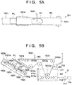
- the supplied liquid W2 is retained in the hydrophilic region R1 and forms a liquid pool, as shown in Fig. 5A .
- the motor 1013 shown in Fig. 2 is driven to rotate the pulley 1012c in a direction indicated by an arrow A1 in Fig. 6B . Accordingly, the conveyance belt 1011 travels in a direction indicated by an arrow A2, and the hydrophilic region R1 moves to the side of the conveyance terminal end P ED together with the liquid pool retained on it.
- the driving of the motor 1013 is stopped. Almost at the same time as the moving process of the hydrophilic region R1, the liquid supply nozzle 1031 is moved in the direction indicated by the arrow A2 in Figs. 6A and 6B and stopped above the plate PL in the conveyance unit 102.
- two processes are preferably performed in parallel.
- the periods in which the processes are performed may partially overlap, or the other process may be performed in a relatively short time from one process.
- the movement of the hydrophilic region R1 and the movement of the liquid supply nozzle 1031 are performed in parallel, performed partially in the same period, or performed sequentially in a relatively short time.
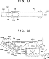
- the observation object OB is placed on the liquid pool of the liquid W2 retained in the hydrophilic region R1.
- the hydrophilic region R1 is surrounded by the water repellent region R2
- the liquid pool is stably maintained on the hydrophilic region R1.
- an interfacial tension acts between the hydrophilic region R1 (placement portion) and the water repellent region R2 (hydrophobic portion).
- a liquid W3 is supplied, by the liquid supply nozzle 1031, to the plate PL in the conveyance unit 102 to make the upper surface of the plate PL wet.
- the conveyance unit 102 is provided such that the plate PL is in a tilting posture. Hence, an excess W3' of the supplied liquid W3 drops downward.
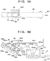
- the liquid supply nozzle 1031 is moved in a direction indicated by an arrow A3 in Figs. 9A and 9B and stopped above the convex portion R1a of the hydrophilic region R1.
- the tilt mechanism 1014 is driven to bend the conveyance terminal end P ED in a direction indicated by an arrow A4 in Fig. 9B to set the conveyance terminal end P ED in a state in which it tilts (to be sometimes simply expressed as a "tilt state” hereinafter) and bring the conveyance terminal end P ED close to the plate PL in the conveyance unit 102.
- the motor 1013 is driven again to rotate the pulley 1012c in a direction indicated by an arrow A5 in Fig. 10B and make the belt 1011 travel. Accordingly, the observation object OB on the liquid pool retained in the hydrophilic region R1 is conveyed to the side of the conveyance unit 102 close to the conveyance terminal end P ED . Almost at the same time as the conveyance process of the observation object OB, the motor 102a is driven to make the conveyance belt 1021 travel. Accordingly, the plate PL moves obliquely upward along the direction of the arrow D1. Additionally, almost at the same time as the conveyance process of the plate PL, a liquid W4 is supplied to the portion R1 a of the hydrophilic region R1 by the liquid supply nozzle 1031
- three operations that is, the conveyance of the observation object OB by the conveyance unit 101, the conveyance of the plate PL by the conveyance unit 102, and the supply of the liquid W4 on the upstream side of the observation object OB are performed in parallel.
- the three operations are preferably executed in parallel/in a superimposed manner at least for a predetermined period.
- the start and/or end timings of the operations need not always match.
- the observation object OB is placed on the flow of the supplied liquid W4.
- the observation object OB is transferred onto the plate PL together with the liquid W4.
- the observation object OB is washed away by the liquid W4 onto the plate PL together with the liquid pool.
- the plate PL is transferred upward along a direction indicted by an arrow A7 in Fig. 11B , that is, the direction of tilt of the placement plate 102e.
- the observation object OB is placed on the plate PL and appropriately transferred onto the plate PL together with the liquid pool and the liquid W4 without mixing bubbles in the observation object OB.
- the observation object OB is thus transferred onto the plate PL, and the observation specimen SP is prepared. Note that the excess W4' of the liquid W4 flowing onto the plate PL together with the observation object OB drops downward along the placement plate 102e of the conveyance unit 102.
- the placement plate 102e with the observation specimen SP is transferred by the conveyance unit 102 in the direction indicated by the arrow A7 in Fig. 11B and then stopped at a position where the above-described manipulator 4 (see Fig. 1 ) can grip the observation specimen SP.
- the stop position is located at the upper end of the guide member 102g, and may be called an upper stop position, an upper stop point, or the like.
- the manipulator 4 grips the observation specimen SP, extracts it from the placement plate 102e, and stores it in the specimen storage 3.
- the conveyance belt 1011 is continuously made to travel and guided into the storage unit 111a of the cleaning unit 11.
- the conveyance belt 1011 is thus cleaned by the cleaning liquid W1 in the storage unit 111a so as to be in a state in which the next (another) observation object OB can be placed in the hydrophilic region R1.
- the belt 1011 passes through the cleaning liquid W1 in the storage unit 111a.
- the conveyance unit 101 is configured to form a folded portion in which the conveyance belt 1011 is folded in a V shape by the pulleys 1012a, 1012d, and 1012e.
- the conveyance belt 1011 includes a portion (first traveling portion) that travels downward from the pulley 1012e to the pulley 1012d to pass through the storage unit 111a and a portion (second traveling portion) that is folded from this portion and travels upward from the pulley 1012d to the pulley 1012a.
- the conveyance belt 1011 can thus pass through the cleaning liquid W1 in the storage unit 111a.
- ultrasonic cleaning by the ultrasonic generation unit 112 is performed for the conveyance belt 1011.
- Adhered substances such as protein and contamination adhered to the conveyance belt 1011 are peeled off by a cavitation or the like generated by the ultrasonic vibration and float on the surface of the cleaning liquid W1.
- the cleaning liquid W1 is sufficiently supplied from the cleaning liquid tank 114, the cleaning liquid W1 in the storage unit 111a overflows. Along with the overflow of the cleaning liquid W1, the adhered substances floating on the surface of the cleaning liquid W1 are discharged to the liquid discharge unit 111b. As a result, the cleaning liquid W1 stored in the storage unit 111a is kept clean.
- a cleaning liquid (an unused cleaning liquid or a cleaning liquid after the cleaning process) W5 for finishing is supplied from the supply unit 113 to the conveyance belt 1011 that has passed through the cleaning liquid W1 in the storage unit 111a.
- the cleaning liquid W1 adhered to the surface of the conveyance belt 1011 is thus washed away by the cleaning liquid W5 for finishing.
- the cleaning liquid W5 supplied from the supply unit 113 to the conveyance belt 1011 directly drops into the container 111 and is stored as the relatively clean cleaning liquid W1 in the container 111.
- the cleaning liquid W1 and the liquids W2 to W4 are pure water in this embodiment, but some/all of them may be solutions different from each other.
- the cleaning liquid W5 for finishing may be the same liquid as the liquids W2 to W4.
- the observation specimen SP using the observation object OB is prepared in the above-described way.
- the tilt mechanism 1014 is driven to return the conveyance terminal end P ED to the level state, and the processes shown in Figs. 5A and 5B to 12A and 12B are performed for the next observation object OB in a similar manner.
- the observation object OB conveyed by the conveyance unit 101 can appropriately be transferred onto the plate PL conveyed by the conveyance unit 102. More specifically, as described with reference to Figs. 10A to 11B , at the time of transfer, the liquid W4 is supplied to the conveyance unit 101 by the liquid supply nozzle 1031, and the observation object OB is transferred onto the plate PL together with the liquid W4. At this time, the observation object OB is carried by the flow of the liquid W4, and is thus released from the conveyance unit 101 and transferred onto the plate PL. According to this embodiment, the observation object OB is washed away by the liquid W4, thereby implementing transfer of the observation object OB onto the plate PL without mixing bubbles between the observation object OB and the plate PL.
- the observation object OB before the transfer of the observation object OB, the observation object OB is placed on the liquid pool of the liquid W2 retained in the hydrophilic region R1 in the conveyance unit 101.
- the liquid pool assists or promotes the wash-away of the observation object OB by the supplied liquid W4. That is, when the liquid W4 is further supplied to the hydrophilic region R1, the observation object OB on the liquid pool retained in the hydrophilic region R1 is washed away together with the liquid pool and the liquid W4 and thus moved onto the plate PL.
- the bubbles are squeezed out in advance before the transfer of the observation object OB (that is, before the supply of the liquid W4), thereby preventing the bubbles from being mixed between the observation object OB and the plate PL at the time of transfer.
- the liquid pool and the liquid W4 which are moved onto the plate PL when transferring the observation object OB, and the liquid W3 supplied onto the plate PL in advance flow downward due to the water repellency of the plate PL and the tilt of the plate PL itself.
- the liquid pool and the liquids W3 and W4 flow downward, air is not mixed between the observation object OB and the plate PL.
- the observation object OB comes into tight contact with the plate PL.
- the liquid pool and the liquids W3 and W4 need not completely flow downward from the plate PL, and liquids in such an amount that makes the upper surface of the plate PL wet may remain.
- the observation object OB can readily be carried by the flow of the liquid W4.
- the clearance between the plate PL and the conveyance terminal end P ED can be made small, and the fall distance of the observation object OB released from the conveyance terminal end P ED can be made short. This makes it possible to, at the time of transfer of the observation object OB, transfer the observation object OB while substantially keeping it in a level state. That is, it is possible to prevent the posture of the observation object OB from changing and more appropriately transfer the observation object OB.
- ⁇ 1 be the tilt angle of the conveyance terminal end P ED (the angle made by the level surface and the upper surface of the conveyance terminal end P ED ). If ⁇ 1 is made too large, the posture of the observation object OB may change when transferring the observation object OB. For this reason, for example, the tilt angle ⁇ 1 is set to 5° ⁇ ⁇ 1 ⁇ 30° (preferably 5° ⁇ ⁇ 1 ⁇ 20°) approximately.
- the conveyance terminal end P ED and the plate PL need only be apart to such an extent not to impede traveling of the conveyance belts 1011 and 1021 of the conveyance units 101 and 102.
- the clearance between the plate PL and the conveyance terminal end P ED need only be at least less than the size of the observation object OB, and is preferably a half or less of the size of the observation object OB.
- the conveyance terminal end P ED is set in the tilting state and brought close to the conveyance unit 102 .
- the present invention is not limited to this. That is, at least one of the conveyance unit 101 (especially the conveyance terminal end P ED ) and the conveyance unit 102 is preferably configured to be able to change its position or posture such that they can be close to each other.
- the whole conveyance unit 101 may be tilted or moved such that the conveyance terminal end P ED comes close to the conveyance unit 102.
- the conveyance unit 102 may be tilted or moved to be close to the conveyance terminal end P ED .
- both of the conveyance units 101 and 102 may be configured to be movable to be close to each other.
- the observation object OB is placed on the liquid pool of the liquid W2 retained in the hydrophilic region R1. Since the liquid pool is maintained on the hydrophilic region R1, the placement position of the observation object OB is appropriately maintained. For this reason, at the time of transfer of the observation object OB, the observation object OB can be transferred to a desired position on the plate PL without causing displacement. In addition, when the observation object OB is placed on the liquid pool, sticking of the observation object OB to the upper surface of the conveyance belt 1011 can be prevented, and at the time of transfer of the observation object OB, the observation object OB can appropriately be released from the conveyance terminal end P ED .
- the liquid pool assists or promotes the wash-away of the observation object OB by the supplied liquid W4 onto the plate PL.
- the hydrophilic region R1 surrounded by the water repellent region R2 serves as a placement portion configured to retain the liquid pool of the liquid W2 and place the observation object OB has been described.
- the present invention is not limited to this.
- the concave portion when a concave portion is provided in the upper surface of the conveyance belt 1011, the concave portion can be used as a placement portion capable of retaining the liquid W2.
- the plate PL when the plate PL is wet with the liquid W3 in advance before the transfer of the observation object OB, at the time of transfer, the observation object OB that has come into contact with the upper surface of the plate PL is attracted on the upper surface and appropriately received by the upper surface. At this time, since the plate PL is in the tilting posture, the excess W3' of the liquid W3 drops, and the plate PL appropriately becomes wet.
- ⁇ 2 be the tilt angle of the plate PL (the angle made by the level surface and the upper surface of the plate PL). If ⁇ 2 is made too small, the excess W3' is difficult to drop. If ⁇ 2 is made too large, the observation object OB may fall at the time of transfer of it. For this reason, the tilt angle ⁇ 2 is set to, for example, 40° ⁇ ⁇ 2 ⁇ 65°, and preferably, 45° ⁇ ⁇ 2 ⁇ 60°) approximately.
- the liquid supply unit 103 may further include another liquid supply nozzle fixed above the conveyance unit 102. That is, the liquid supply unit 103 may be provided with two liquid supply nozzles capable of supplying liquids to the conveyance units 101 and 102, respectively.
- the liquid supply nozzle corresponding to the conveyance unit 102 may be a spray type nozzle.
- the present invention is not limited to the above-described examples and may partially be changed without departing from the scope of the present invention, and for example, the features of the embodiments may be combined. For example, some of the processes shown in Figs. 5A and 5B to 12A and 12B may be omitted, another process may be added, or the order of the processes may be changed. Individual terms described in this specification are merely used for the purpose of explaining the present invention, and the present invention is not limited to the strict meanings of the terms and can also incorporate their equivalents.
Landscapes
- Health & Medical Sciences (AREA)
- Chemical & Material Sciences (AREA)
- Life Sciences & Earth Sciences (AREA)
- Immunology (AREA)
- Biochemistry (AREA)
- General Health & Medical Sciences (AREA)
- General Physics & Mathematics (AREA)
- Physics & Mathematics (AREA)
- Pathology (AREA)
- Analytical Chemistry (AREA)
- Chemical Kinetics & Catalysis (AREA)
- Clinical Laboratory Science (AREA)
- Medicinal Chemistry (AREA)
- Engineering & Computer Science (AREA)
- Biomedical Technology (AREA)
- Molecular Biology (AREA)
- Sampling And Sample Adjustment (AREA)
Abstract
Description
- The present invention relates to a specimen preparation method and a specimen preparation device.
- An observation specimen used in a microscope observation or the like is generally prepared by placing an observation object (tissue piece) on a translucent plate (microscope slide).
PTL 1 discloses the structure of a specimen preparation device that prepares an observation specimen. This specimen preparation device includes a conveyance belt configured to convey an observation object, and conveys the observation object held on the lower surface of the belt by static electricity. According toPTL 1, transfer of the observation object from the lower surface of the belt onto a plate is done by loosening the belt and bringing the lower surface of the belt into contact with the plate arranged under the belt. - PTL 1: Japanese Patent Laid-Open No.
2008-151657 - According to
PTL 1, when transferring the observation object, for example, bubbles may be mixed between the observation object and the plate, and the observation specimen may not be appropriately prepared. Additionally, in the structure ofPTL 1, a mechanism configured to hold an observation object on the lower surface of the belt by static electricity or release it from the lower surface, a mechanism configured to bring the lower surface of the belt into contact with a plate, and the like are necessary, resulting in a bulky and complex device. - It is an object of the present invention to prepare an observation specimen by transferring an observation object onto a plate without mixture of bubbles by a relatively simple arrangement.
- According to an aspect of the present invention, there is provided a specimen preparation method of preparing an observation specimen by placing an observation object on a light transmitting plate, characterized by comprising a conveyance step of conveying the observation object by a conveyance mechanism including a placement portion configured to place the observation object, and a transfer step of transferring the observation object from the placement portion of the conveyance mechanism onto the plate at a conveyance terminal end of the conveyance mechanism, wherein in the transfer step, a liquid is supplied to the placement portion on which the observation object is placed, and the observation object is carried by a flow of the liquid and transferred onto the plate.
- According to another aspect of the present invention, there is provided a specimen preparation device configured to prepare an observation specimen including an observation object placed on a light transmitting plate, characterized by comprising first conveyance means, including a placement portion configured to place the observation object, for moving the placement portion and conveying the observation object, second conveyance means for conveying the plate such that the plate passes a position where the observation object is transferred, and liquid supply means for supplying a liquid to the placement portion at a conveyance terminal end of the first conveyance means.
- According to the present invention, it is possible to prepare an observation specimen by transferring an observation object onto a plate without mixture of bubbles.
- Other features and advantages of the present invention will be apparent from the following descriptions taken in conjunction with the accompanying drawings, in which like reference characters designate the same or similar parts throughout the figures thereof.
- The accompanying drawings, which are incorporated in and constitute a part of the specification, illustrate embodiments of the invention and, together with the description, serve to explain the principles of the invention.
-
Fig. 1 is a block diagram for explaining an example of the arrangement of a specimen management system; -
Fig. 2 is a perspective view for explaining an example of the arrangement of a specimen preparation device; -
Fig. 3 is a perspective view for explaining a conveyance unit configured to convey an observation object; -
Fig. 4A is a view for explaining part of a specimen preparation form by the specimen preparation device; -
Fig. 4B is a view for explaining part of the specimen preparation form by the specimen preparation device; -
Fig. 5A is a view for explaining part of the specimen preparation form by the specimen preparation device; -
Fig. 5B is a view for explaining part of the specimen preparation form by the specimen preparation device; -
Fig. 6A is a view for explaining part of the specimen preparation form by the specimen preparation device; -
Fig. 6B is a view for explaining part of the specimen preparation form by the specimen preparation device; -
Fig. 7A is a view for explaining part of the specimen preparation form by the specimen preparation device; -
Fig. 7B is a view for explaining part of the specimen preparation form by the specimen preparation device; -
Fig. 8A is a view for explaining part of the specimen preparation form by the specimen preparation device; -
Fig. 8B is a view for explaining part of the specimen preparation form by the specimen preparation device; -
Fig. 9A is a view for explaining part of the specimen preparation form by the specimen preparation device; -
Fig. 9B is a view for explaining part of the specimen preparation form by the specimen preparation device; -
Fig. 10A is a view for explaining part of the specimen preparation form by the specimen preparation device; -
Fig. 10B is a view for explaining part of the specimen preparation form by the specimen preparation device; -
Fig. 11A is a view for explaining part of the specimen preparation form by the specimen preparation device; -
Fig. 11B is a view for explaining part of the specimen preparation form by the specimen preparation device; -
Fig. 12A is a view for explaining part of the specimen preparation form by the specimen preparation device; and -
Fig. 12B is a view for explaining part of the specimen preparation form by the specimen preparation device. - Embodiments of the present invention will now be described with reference to the accompanying drawings. Note that the drawings are schematic views showing structures or arrangements according to the embodiments, and the dimensions of members shown in the drawings do not necessarily reflect the actuality.
-
Fig. 1 is a block diagram showing an example of the arrangement of a specimen management system SY according to the embodiment. The specimen management system SY includes aspecimen preparation device 1, aplate storage 2, aspecimen storage 3, amanipulator 4, and acontroller 5. - The
specimen preparation device 1 receives an observation object OB that becomes an observation target in a microscope observation or the like, and a light transmitting plate PL used to place the observation object, and places the observation object OB on the plate PL, thereby preparing an observation specimen SP. The observation object OB is a tissue collected from a subject such as a patient, and is typically a sliced tissue piece. The observation specimen SP may be referred to as a tissue specimen or simply as a specimen. The plate PL is a so-called microscope slide, and may be referred to as a placement plate, an optical observation plate, or the like. As another embodiment, a cover glass may further be placed on the plate PL to cover the observation object OB. - The
plate storage 2 can store the plate PL provided to thespecimen preparation device 1 later. Thespecimen storage 3 can store the observation specimen SP (that is, the plate PL on which the observation object OB is placed) prepared by thespecimen preparation device 1. Themanipulator 4 includes a hand (end effector) capable of gripping the plate PL or the observation object OB. By themanipulator 4, the plate PL is transferred from theplate storage 2 to thespecimen preparation device 1, and the observation specimen SP is transferred from thespecimen preparation device 1 to thespecimen storage 3. For example, themanipulator 4 extracts the plate PL from theplate storage 2 and provides it to thespecimen preparation device 1, and also receives the observation specimen SP from thespecimen preparation device 1 and stores it in thespecimen storage 3. As themanipulator 4, for example, a SCARA robot or a vertical 6-axis robot (preferably, a collaborative robot having high collaborative workability with an operator to be described later) can be used. - The
controller 5 can control, for example, the operations of thespecimen preparation device 1 and themanipulator 4, and can also manage the number of plates PL in stock in theplate storage 2, the number of observation specimens SP stored in thespecimen storage 3, and the like. As thecontroller 5, a semiconductor device such as an ASIC (Application Specific Integrated Circuit) or a PLD (Programmable Logic Device) having a function of performing the control and management can be used. Alternatively, thecontroller 5 may be formed by a CPU (Central Processing Unit) and a memory, and can perform the control and management by reading out and executing a predetermined program. That is, the function of thecontroller 5 can be implemented by either hardware or software. -
Fig. 2 is a perspective view showing the structure of thespecimen preparation device 1. Thespecimen preparation device 1 includes a pair oftransfer units cleaning unit 11. Thetransfer unit 10A includes aconveyance unit 101, aconveyance unit 102, and aliquid supply unit 103. Thetransfer unit 10B is provided to be bilaterally symmetrical to thetransfer unit 10A, and has a structure similar to that of thetransfer unit 10A. Details of the structure will be described below with focus on thetransfer unit 10A. - The
conveyance unit 101 can convey the observation object OB placed on the placement surface. In this embodiment, placement of the observation object OB on the placement surface is performed by an operator such as a pathologist using a predetermined tool. As another embodiment, the placement may be done by themanipulator 4, or may be done by another manipulator different from themanipulator 4. In this embodiment, theconveyance unit 101 is a conveyance mechanism (belt mechanism) including aconveyance belt 1011 that forms the placement surface, as will be described later in detail. The surface of theconveyance belt 1011 on the obverse side, that is, the outer surface of theconveyance belt 1011 formed into an annular shape is the placement surface (conveyance surface), and the observation object OB is placed on the placement surface. - The
conveyance unit 102 can convey the plate PL placed on the placement surface. In this embodiment, placement of the plate PL on the placement surface is performed by themanipulator 4. However, as another embodiment, the operator may perform the placement. In this embodiment, theconveyance unit 102 includes aplacement plate 102e on which the plate PL is placed, as will be described later in detail. Theplacement plate 102e moves along an oblique direction (the direction of an arrow DI inFig. 4B to be described later). - The
liquid supply unit 103 is configured to be able to supply a liquid to both of theconveyance units liquid supply nozzle 1031, aslider mechanism 1032, aguiderail 1033, aslider belt 1034, a pair ofpulleys 1036, and amotor 1035. Theliquid supply nozzle 1031 includes an opening capable of discharging a liquid. In this embodiment, pure water is used as the liquid. As another embodiment, a liquid (a solution or a chemical solution) having no substantial chemical influence on the observation object OB, for example, a physiological saline may be used. - The
slider mechanism 1032 fixes the base of theliquid supply nozzle 1031, and is configured to be slidable along theguiderail 1033. In this embodiment, the driving force of themotor 1035 is transmitted to one of the pair ofpulleys 1036, whereby the slider belt (timing belt) 1034 stretched between the pair ofpulleys 1036 travels. Along with the traveling of theslider belt 1034, theslider mechanism 1032 fixed to theslider belt 1034 is driven. When theslider mechanism 1032 travels along theguiderail 1033, theliquid supply nozzle 1031 reciprocally moves between theconveyance units - When transferring the observation object OB conveyed by the
conveyance unit 101 onto the plate PL conveyed by the conveyance unit 102 (to be sometimes expressed as "transfer of the observation object OB" or simply "transfer" hereinafter), theliquid supply unit 103 supplies a liquid to each of theconveyance units slider belt 1034 is used to transmit the driving force of themotor 1035 to theslider mechanism 1032. However, another linear driving mechanism, for example, a linear motor, a ball screw, a cylinder, a rack and pinion, a chain, or the like may be used. - The
cleaning unit 11 is configured to be able to clean theconveyance belt 1011 of theconveyance unit 101 in each of thetransfer units container 111, anultrasonic generation unit 112, and asupply unit 113, as will be described later in detail. Thecontainer 111 includes astorage unit 111a and aliquid discharge unit 111b. Thestorage unit 111a stores a cleaning liquid W1 that is a liquid used to clean theconveyance belt 1011. Thestorage unit 111a is connected to a cleaningliquid tank 114 via asupply line 115. Theliquid discharge unit 111b temporarily stores the cleaning liquid W1 overflowing from thestorage unit 111a and discharges it. Theultrasonic generation unit 112 is arranged on the bottom portion of thecontainer 111, and applies an ultrasonic vibration to the cleaning liquid W1 in thecontainer 111, thereby generating a cavitation in the cleaning liquid W1. In addition, thesupply unit 113 supplies a cleaning liquid for finishing to theconveyance belt 1011 cleaned by the cleaning liquid W1. -
Fig. 3 is a perspective view showing the structure of theconveyance unit 101. Theconveyance unit 101 includespulleys 1012a to 1012e, amotor 1013, atilt mechanism 1014, and ahousing 1015 in addition to the above-describedconveyance belt 1011. Theconveyance belt 1011 is a strip-shaped endless traveling body made of, for example, rubber or the like, and conveys the observation object OB placed on the placement surface, as described above. Note that theconveyance unit 101 shown inFig. 3 is theconveyance unit 101 of thetransfer unit 10B, and has a structure symmetrical to theconveyance unit 101 of thetransfer unit 10A. - The
conveyance unit 101 is configured to form a folded portion in which theconveyance belt 1011 is folded in a V shape by thepulleys conveyance belt 1011 passes through the cleaning liquid W1 in thecontainer 111, as will be described later in detail. When theconveyance unit 101 and thecontainer 111 are arranged such that the part of the folded portion is immersed in the cleaning liquid W1, theconveyance belt 1011 passing in thecontainer 111 is cleaned by the cavitation in the cleaning liquid W1. Note that the frequency of the ultrasonic wave generated by theultrasonic generation unit 112 is, for example, about 40 kHz to 170 kHz, but may be changed or adjusted as needed. - With this arrangement, the
specimen preparation device 1 sequentially performs preparation of the observation specimen SP and cleaning of theconveyance belt 1011 of theconveyance unit 101 by thecleaning unit 11 in each of thetransfer units transfer units conveyance belt 1011 of theconveyance unit 101 and placement or setting of the observation object OB may be performed in the other. However, works of same contents may be performed in both transfer units in parallel. - Referring back to
Fig. 3 , in this embodiment, theconveyance belt 1011 includes a hydrophilic region R1 and a water repellent region (hydrophobic region) R2 on the upper surface. The hydrophilic region R1 is a region of high wettability, and can retain (or store) a liquid when the liquid is supplied. The water repellent region R2 has a water repellent effect of repelling a liquid when the liquid is supplied. - In this embodiment, the hydrophilic region R1 is surrounded by the water repellent region R2. For this reason, the liquid retained in the hydrophilic region R1 is repelled by the water repellent region R2 toward the center of the hydrophilic region R1 even if the liquid is going to flow outward (in all directions from the hydrophilic region R1 toward the water repellent region R2). Hence, the liquid is continuously retained in the hydrophilic region R1 and forms a liquid pool without spreading out of the hydrophilic region R1. The observation object OB is placed on the liquid pool retained in the hydrophilic region R1. That is, the hydrophilic region R1 corresponds to a placement portion used to place the observation object OB.
- The hydrophilic region R1 and the water repellent region R2 can have a relative relationship determined by the difference of the property to the liquid on the upper surface. The hydrophilic region R1 and the water repellent region R2 may be provided such that the contact angle of a liquid droplet on the upper surface satisfies a predetermined condition. For example, letting θw be the contact angle of a liquid droplet of pure water, the hydrophilic region R1 preferably satisfies at least a super-hydrophilicity represented by θw ≤ 10°, and more preferably, θw ≤ 5°. The water repellent region R2 is preferably provided such that the contact angle θw in the water repellent region R2 becomes larger than at least the contact angle θw in the hydrophilic region R1. The water repellent region R2 preferably satisfies a water repellency represented by θw ≥ 90°, more preferably, a high water repellency represented by θw ≥ 120°, and much more preferably, a super water repellency represented by θw ≥ 150°.
- In this embodiment, the hydrophilic region R1 is provided in an almost rectangular shape at the center of the
conveyance belt 1011 in the widthwise direction (the direction orthogonal to the conveyance direction of the conveyance belt 1011), and the water repellent region R2 is formed at two ends. In addition, two or more hydrophilic regions R1 may be provided in the conveyance direction of theconveyance belt 1011. For example, in a case in which two hydrophilic regions R1 are provided on the upper surface of theconveyance belt 1011, when one of them is being used to transfer the observation object OB, the other can be cleaned by thecleaning unit 11. The hydrophilic region R1 includes a portion R1a formed into a convex shape on the upstream side of the conveyance direction, as will be described later in detail. - The hydrophilic region R1 is formed, for example, in the following way. First, the
conveyance belt 1011 itself is formed using a hydrophilic material. After that, an evaporated film, a coat, or a film of a water repellent material is provided on a portion of the surface of theconveyance belt 1011 other than the hydrophilic region R1, in other words, a portion that surrounds the hydrophilic region R1, thereby forming the water repellent region R2. The hydrophilic region R1 may be formed in the following way. First, the surface of a desired region of theconveyance belt 1011 made of a common belt material is coated with a titanium oxide film. After that, the coating region of the titanium oxide film is irradiated with ultraviolet rays, thereby forming the irradiated region into the hydrophilic region R1. - On the other hand, the water repellent region R2 may be formed, for example, in the following way. First, the
conveyance belt 1011 itself is formed using a water repellent material. After the surface of a desired region of theconveyance belt 1011 is coated with a titanium oxide film, the coating region of the titanium oxide film is irradiated with ultraviolet rays, thereby forming the irradiated region into the hydrophilic region R1. The whole region other than the hydrophilic region R1 is the water repellent region R2. The water repellent region R2 may be formed in the following way. A surface roughening film body (a film body with a number of extra-fine projecting portions on the surface) transferred by a nanoimprinting method is pasted to a portion surrounding the hydrophilic region R1 on the surface of theconveyance belt 1011. In addition, the film body is coated with a low surface energy substance, or a low surface energy material is mixed or polymerized in the film body itself, thereby forming the film body into the water repellent region R2. - The
pulleys 1012a to 1012e are arranged to allow theconveyance belt 101 1 to travel, and fix the position of theconveyance belt 1011. Thepulley 1012a is arranged on the side of a conveyance start end PST of theconveyance belt 1011, that is, on the upstream side (the right side inFig. 3 ) of the conveyance direction of theconveyance belt 1011. Thepulley 1012b is arranged on the side of a conveyance terminal end PED of thebelt 1011, that is, on the downstream side (the left side inFig. 3 ) of the conveyance direction of thebelt 1011. Thepulleys 1012c to 1012e are arranged to guide theconveyance belt 1011 that has ended the conveyance of the observation object OB at the conveyance terminal end PED to the side of the conveyance terminal end PED again. - In this embodiment, the
pulley 1012c is arranged on the lower side of the conveyance terminal end PED, and thepulley 1012d is arranged on the lower side of the conveyance start end PST. Thepulley 1012e is arranged between thepulleys pulleys 1012a to 1012e, theconveyance belt 1011 that has ended the conveyance at the conveyance terminal end PED readily passes through the above-describedcleaning unit 11. - In this embodiment, the
motor 1013 is arranged on the lower side of thepulley 1012c and apulley 1016a on the same axis as that, and the driving force of themotor 1013 is transmitted to thepulley 1016a via a toothed belt (timing belt) 1018a. The rotation of thepulley 1016a is directly input to thepulley 1012c. When thepulley 1012c receives the driving force from themotor 1013 and thus rotates, theconveyance belt 1011 travels. In this embodiment, themotor 1013 is arranged on the lower side of thepulley 1012c. As another embodiment, themotor 1013 may be arranged on the lower side of another pulley, for example, thepulley 1012b. - The
tilt mechanism 1014 is configured to be able to tilt the conveyance terminal end PED and, in this embodiment, includes aguide portion 10141 and amotor 1017. The driving force of themotor 1017 is transmitted to apulley 1016b via a toothed belt (timing belt) 1018b. Thepulley 1016b is rigidly connected to theguide portion 10141, and the rotation of thepulley 1016b is directly input to theguide portion 10141. This allows theguide portion 10141 to receive the driving force from themotor 1017 and tilt. In other words, the pivotal motion of themotor 1017 is converted into the tilting motion of theguide portion 10141. - With this arrangement, the
tilt mechanism 1014 can make the upper surface of theconveyance belt 1011 level/flat entirely from the conveyance start end PST to the conveyance terminal end PED, or can bend the conveyance terminal end PED downward with respect to the conveyance start end PST. Note that a small roller may be provided at the distal end of theguide portion 10141 such that theconveyance belt 1011 readily travels. Alternatively, to reduce the frictional resistance between theguide portion 10141 and theconveyance belt 1011, they may be configured as follows. That is, - at least the distal end surface of the
guide portion 10141 is covered with a material of a low frictional resistance, - the lower surface of the
conveyance belt 1011 is covered with a material of a low frictional resistance, or - the
guide portion 10141 itself is made of a material of a low frictional resistance. - In this specification, tilt means a posture or state in which a tilt occurs with respect to a level surface. In this embodiment, the tilt of the conveyance terminal end PED is implemented by bending the conveyance terminal end PED downward with respect to the conveyance start end PST by the
tilt mechanism 1014. The conveyance terminal end PED can freely be moved close to or far away from theconveyance unit 102 by thetilt mechanism 1014, as will be described later in detail. - A pair of
housings 1015 are arranged to sandwich theconveyance belt 1011, thepulleys 1012a to 1012e, and thetilt mechanism 1014. By the pair ofhousings 1015, thepulleys 1012a to 1012e and thetilt mechanism 1014 are supported, and theconveyance belt 1011 can be made to travel stably. In addition, the pair ofhousings 1015 are provided such that the upper end of each of them is located above the upper traveling surface of theconveyance belt 1011. This prevents the observation object OB conveyed by theconveyance belt 1011 from falling from both sides of the belt during conveyance. - A form of a specimen preparation method according to this embodiment will be described below with reference to
Figs. 4A to 12B . As the outline of the method, when transferring the observation object OB conveyed by theconveyance unit 101 onto the plate PL conveyed by theconveyance unit 102, a liquid is supplied to theconveyance unit 101 by theliquid supply nozzle 1031. Then, the observation object OB is transferred onto the plate PL together with the liquid. - First, in a process shown in
Figs. 4A and 4B , the plate PL is set in theconveyance unit 102.Figs. 4A shows a plan view of theconveyance unit 101, andFig. 4B shows a side view of theconveyance unit 101 together with theconveyance unit 102. Note that the views (Figs. 5A and 5B and subsequent views) for explaining the contents after this process also show a plan view and a side view. - Here, as shown in
FIG. 4B , (partially shown inFig. 2 as well), theconveyance unit 102 includes a drivingmotor 102a, a drivingpulley 102b, a drivenpulley 102c, aconveyance belt 1021, abracket 102d, aplacement plate 102e, asupport member 102f, and aguide member 102g. The drivingmotor 102a is attached to a side surface of thesupport member 102f on one side, and the drivingpulley 102b and the drivenpulley 102c are attached to a side surface on the other side. Theconveyance belt 1021 is stretched between the drivingpulley 102b and the drivenpulley 102c. Thebracket 102d is a Z-shaped (crank-shaped) member, and has one end fixed to anupper traveling portion 1021a of theconveyance belt 1021. Theplacement plate 102e is provided on the other end. - The
guide member 102g is provided along the direction DI on the side surface of thesupport member 102f on the other side (the side surface to which the drivingpulley 102b and the drivenpulley 102c are attached). A surface of thebracket 102d facing thesupport member 102f is provided with aslider 102h that is slidable along theguide member 102g. - According to this arrangement, when the driving
pulley 102b receives a driving force from the drivingmotor 102a and rotates, theconveyance belt 1021 travels. Theslider 102h on thebracket 102d thus slides along theguide member 102g, and theplacement plate 102e moves along the direction DI. - Note that in this process, the
tilt mechanism 1014 is assumed to maintain the upper surface of theconveyance belt 1011 entirely from the conveyance start end PST to the conveyance terminal end PED (seeFig. 3 ) in a state in which the upper surface is level (to be sometimes simply expressed as a "level state" hereinafter). - Next, in a process shown in
Figs. 5 and 5B , a liquid W2 is supplied, by theliquid supply nozzle 1031, to the hydrophilic region R1 on theconveyance belt 1011 of theconveyance unit 101. As described above, the hydrophilic region R1 is surrounded by the water repellent region R2. Hence, the supplied liquid W2 is retained in the hydrophilic region R1 and forms a liquid pool, as shown inFig. 5A . - Next, the
motor 1013 shown inFig. 2 is driven to rotate thepulley 1012c in a direction indicated by an arrow A1 inFig. 6B . Accordingly, theconveyance belt 1011 travels in a direction indicated by an arrow A2, and the hydrophilic region R1 moves to the side of the conveyance terminal end PED together with the liquid pool retained on it. When the hydrophilic region R1 moves to the side of the conveyance terminal end PED, the driving of themotor 1013 is stopped. Almost at the same time as the moving process of the hydrophilic region R1, theliquid supply nozzle 1031 is moved in the direction indicated by the arrow A2 inFigs. 6A and 6B and stopped above the plate PL in theconveyance unit 102. - Note that in this specification, concerning "almost at the same time", two processes are preferably performed in parallel. However, the periods in which the processes are performed may partially overlap, or the other process may be performed in a relatively short time from one process. For example, in the process shown in
Figs. 6 and 6B , the movement of the hydrophilic region R1 and the movement of theliquid supply nozzle 1031 are performed in parallel, performed partially in the same period, or performed sequentially in a relatively short time. - Next, in a process shown in
Figs. 7 and 7B , the observation object OB is placed on the liquid pool of the liquid W2 retained in the hydrophilic region R1. At this time, since the hydrophilic region R1 is surrounded by the water repellent region R2, the liquid pool is stably maintained on the hydrophilic region R1. At this time, an interfacial tension acts between the hydrophilic region R1 (placement portion) and the water repellent region R2 (hydrophobic portion). By the interfacial tension, a force of pulling to the center of the liquid pool surface acts on the observation object OB. Accordingly, the observation object OB is maintained in a state in which it is always centered toward the center of the liquid pool surface. For this reason, displacement of the observation object OB hardly occurs on the liquid pool. Even if the observation object OB is displaced by the tilt of theconveyance belt 1011 or a vibration generated at the time of traveling of theconveyance belt 1011, the observation object OB is immediately held at the center of the surface of the liquid pool because it is always centered toward the center of the liquid pool surface. Here, if bubbles are mixed between the observation object OB and the liquid pool when the observation object OB is placed on the liquid pool, the bubbles are preferably squeezed out at this point of time. - Next, in a process shown in
Figs. 8 and 8B , a liquid W3 is supplied, by theliquid supply nozzle 1031, to the plate PL in theconveyance unit 102 to make the upper surface of the plate PL wet. Here, as is apparent fromFig. 8B , theconveyance unit 102 is provided such that the plate PL is in a tilting posture. Hence, an excess W3' of the supplied liquid W3 drops downward. - Next, in a process shown in
Figs. 9 and 9B , theliquid supply nozzle 1031 is moved in a direction indicated by an arrow A3 inFigs. 9A and 9B and stopped above the convex portion R1a of the hydrophilic region R1. Almost at the same time as the moving process of theliquid supply nozzle 1031, thetilt mechanism 1014 is driven to bend the conveyance terminal end PED in a direction indicated by an arrow A4 inFig. 9B to set the conveyance terminal end PED in a state in which it tilts (to be sometimes simply expressed as a "tilt state" hereinafter) and bring the conveyance terminal end PED close to the plate PL in theconveyance unit 102. - Next, in a process shown in
Figs. 10 and 10B , themotor 1013 is driven again to rotate thepulley 1012c in a direction indicated by an arrow A5 inFig. 10B and make thebelt 1011 travel. Accordingly, the observation object OB on the liquid pool retained in the hydrophilic region R1 is conveyed to the side of theconveyance unit 102 close to the conveyance terminal end PED. Almost at the same time as the conveyance process of the observation object OB, themotor 102a is driven to make theconveyance belt 1021 travel. Accordingly, the plate PL moves obliquely upward along the direction of the arrow D1. Additionally, almost at the same time as the conveyance process of the plate PL, a liquid W4 is supplied to the portion R1 a of the hydrophilic region R1 by theliquid supply nozzle 1031 - That is, in the transfer process of the observation object OB shown in
Figs. 10A and 10B , three operations, that is, the conveyance of the observation object OB by theconveyance unit 101, the conveyance of the plate PL by theconveyance unit 102, and the supply of the liquid W4 on the upstream side of the observation object OB are performed in parallel. The three operations are preferably executed in parallel/in a superimposed manner at least for a predetermined period. However, the start and/or end timings of the operations need not always match. - Note that since the
conveyance unit 102 is provided such that the plate PL is in a tilting posture, an excess W4' of the supplied liquid W4 drops downward in this process as well. - In a process shown in
Figs. 11 and 11B , while the conveyance of the observation object OB by theconveyance unit 101 and the conveyance of the plate PL by theconveyance unit 102 are continuously performed, the observation object OB is placed on the flow of the supplied liquid W4. The observation object OB is transferred onto the plate PL together with the liquid W4. In another expression, the observation object OB is washed away by the liquid W4 onto the plate PL together with the liquid pool. - In this process, the plate PL is transferred upward along a direction indicted by an arrow A7 in
Fig. 11B , that is, the direction of tilt of theplacement plate 102e. For this reason, when carried (dropped) from theconveyance belt 1011 of theconveyance unit 101 at the conveyance terminal end PED, the observation object OB is placed on the plate PL and appropriately transferred onto the plate PL together with the liquid pool and the liquid W4 without mixing bubbles in the observation object OB. The observation object OB is thus transferred onto the plate PL, and the observation specimen SP is prepared. Note that the excess W4' of the liquid W4 flowing onto the plate PL together with the observation object OB drops downward along theplacement plate 102e of theconveyance unit 102. - In a process shown in
Figs. 12 and 12B , theplacement plate 102e with the observation specimen SP is transferred by theconveyance unit 102 in the direction indicated by the arrow A7 inFig. 11B and then stopped at a position where the above-described manipulator 4 (seeFig. 1 ) can grip the observation specimen SP. The stop position is located at the upper end of theguide member 102g, and may be called an upper stop position, an upper stop point, or the like. After that, themanipulator 4 grips the observation specimen SP, extracts it from theplacement plate 102e, and stores it in thespecimen storage 3. - Additionally, in this process, even after the observation object OB is released from the
conveyance belt 1011 of theconveyance unit 101, that is, even after the observation object OB is transferred onto the plate PL, theconveyance belt 1011 is continuously made to travel and guided into thestorage unit 111a of thecleaning unit 11. Theconveyance belt 1011 is thus cleaned by the cleaning liquid W1 in thestorage unit 111a so as to be in a state in which the next (another) observation object OB can be placed in the hydrophilic region R1. - As is apparent from the side views of
Figs. 5B ,6B ,7B ,8B ,9B ,10B ,11B , and12B , since thepulleys container 111, and thepulley 1012d is located in thecontainer 111, thebelt 1011 passes through the cleaning liquid W1 in thestorage unit 111a. As described above, theconveyance unit 101 is configured to form a folded portion in which theconveyance belt 1011 is folded in a V shape by thepulleys conveyance belt 1011 includes a portion (first traveling portion) that travels downward from thepulley 1012e to thepulley 1012d to pass through thestorage unit 111a and a portion (second traveling portion) that is folded from this portion and travels upward from thepulley 1012d to thepulley 1012a. - The
conveyance belt 1011 can thus pass through the cleaning liquid W1 in thestorage unit 111a. When theconveyance belt 1011 passes through the cleaning liquid W1, ultrasonic cleaning by theultrasonic generation unit 112 is performed for theconveyance belt 1011. Adhered substances such as protein and contamination adhered to theconveyance belt 1011 are peeled off by a cavitation or the like generated by the ultrasonic vibration and float on the surface of the cleaning liquid W1. When the cleaning liquid W1 is sufficiently supplied from the cleaningliquid tank 114, the cleaning liquid W1 in thestorage unit 111a overflows. Along with the overflow of the cleaning liquid W1, the adhered substances floating on the surface of the cleaning liquid W1 are discharged to theliquid discharge unit 111b. As a result, the cleaning liquid W1 stored in thestorage unit 111a is kept clean. - A cleaning liquid (an unused cleaning liquid or a cleaning liquid after the cleaning process) W5 for finishing is supplied from the
supply unit 113 to theconveyance belt 1011 that has passed through the cleaning liquid W1 in thestorage unit 111a. The cleaning liquid W1 adhered to the surface of theconveyance belt 1011 is thus washed away by the cleaning liquid W5 for finishing. In this embodiment, since thesupply unit 113 is located above thecontainer 111, the cleaning liquid W5 supplied from thesupply unit 113 to theconveyance belt 1011 directly drops into thecontainer 111 and is stored as the relatively clean cleaning liquid W1 in thecontainer 111. Note that the cleaning liquid W1 and the liquids W2 to W4 are pure water in this embodiment, but some/all of them may be solutions different from each other. In addition, the cleaning liquid W5 for finishing may be the same liquid as the liquids W2 to W4. - The observation specimen SP using the observation object OB is prepared in the above-described way. To prepare another observation specimen SP using another observation object OB after that, the
tilt mechanism 1014 is driven to return the conveyance terminal end PED to the level state, and the processes shown inFigs. 5A and5B to 12A and12B are performed for the next observation object OB in a similar manner. - According to this embodiment, the observation object OB conveyed by the
conveyance unit 101 can appropriately be transferred onto the plate PL conveyed by theconveyance unit 102. More specifically, as described with reference toFigs. 10A to 11B , at the time of transfer, the liquid W4 is supplied to theconveyance unit 101 by theliquid supply nozzle 1031, and the observation object OB is transferred onto the plate PL together with the liquid W4. At this time, the observation object OB is carried by the flow of the liquid W4, and is thus released from theconveyance unit 101 and transferred onto the plate PL. According to this embodiment, the observation object OB is washed away by the liquid W4, thereby implementing transfer of the observation object OB onto the plate PL without mixing bubbles between the observation object OB and the plate PL. - In this embodiment, before the transfer of the observation object OB, the observation object OB is placed on the liquid pool of the liquid W2 retained in the hydrophilic region R1 in the
conveyance unit 101. Hence, when transferring the observation object OB, the liquid pool assists or promotes the wash-away of the observation object OB by the supplied liquid W4. That is, when the liquid W4 is further supplied to the hydrophilic region R1, the observation object OB on the liquid pool retained in the hydrophilic region R1 is washed away together with the liquid pool and the liquid W4 and thus moved onto the plate PL. Here, if bubbles are mixed between the liquid pool and the observation object OB when transferring the observation object OB onto the liquid pool, the bubbles are squeezed out in advance before the transfer of the observation object OB (that is, before the supply of the liquid W4), thereby preventing the bubbles from being mixed between the observation object OB and the plate PL at the time of transfer. - Here, the liquid pool and the liquid W4 which are moved onto the plate PL when transferring the observation object OB, and the liquid W3 supplied onto the plate PL in advance flow downward due to the water repellency of the plate PL and the tilt of the plate PL itself. When the liquid pool and the liquids W3 and W4 flow downward, air is not mixed between the observation object OB and the plate PL. Hence, the observation object OB comes into tight contact with the plate PL. The liquid pool and the liquids W3 and W4 need not completely flow downward from the plate PL, and liquids in such an amount that makes the upper surface of the plate PL wet may remain.
- Additionally, according to this embodiment, since the conveyance terminal end PED of the
conveyance unit 101 is in the tilting state, the observation object OB can readily be carried by the flow of the liquid W4. In addition, when the conveyance terminal end PED is in the tilting state, the clearance between the plate PL and the conveyance terminal end PED can be made small, and the fall distance of the observation object OB released from the conveyance terminal end PED can be made short. This makes it possible to, at the time of transfer of the observation object OB, transfer the observation object OB while substantially keeping it in a level state. That is, it is possible to prevent the posture of the observation object OB from changing and more appropriately transfer the observation object OB. - Let θ1 be the tilt angle of the conveyance terminal end PED (the angle made by the level surface and the upper surface of the conveyance terminal end PED). If θ1 is made too large, the posture of the observation object OB may change when transferring the observation object OB. For this reason, for example, the tilt angle θ1 is set to 5° < θ1 < 30° (preferably 5° < θ1 < 20°) approximately.
- The conveyance terminal end PED and the plate PL need only be apart to such an extent not to impede traveling of the
conveyance belts conveyance units - Here, in this embodiment, a form in which the conveyance terminal end PED is set in the tilting state and brought close to the
conveyance unit 102 has been described. However, the present invention is not limited to this. That is, at least one of the conveyance unit 101 (especially the conveyance terminal end PED) and theconveyance unit 102 is preferably configured to be able to change its position or posture such that they can be close to each other. For example, as another embodiment, thewhole conveyance unit 101 may be tilted or moved such that the conveyance terminal end PED comes close to theconveyance unit 102. Alternatively, theconveyance unit 102 may be tilted or moved to be close to the conveyance terminal end PED. As still another embodiment, both of theconveyance units - Furthermore, according to this embodiment, in the
conveyance unit 101, the observation object OB is placed on the liquid pool of the liquid W2 retained in the hydrophilic region R1. Since the liquid pool is maintained on the hydrophilic region R1, the placement position of the observation object OB is appropriately maintained. For this reason, at the time of transfer of the observation object OB, the observation object OB can be transferred to a desired position on the plate PL without causing displacement. In addition, when the observation object OB is placed on the liquid pool, sticking of the observation object OB to the upper surface of theconveyance belt 1011 can be prevented, and at the time of transfer of the observation object OB, the observation object OB can appropriately be released from the conveyance terminal end PED. Furthermore, as described above, at the time of transfer of the observation object OB, the liquid pool assists or promotes the wash-away of the observation object OB by the supplied liquid W4 onto the plate PL. Hence, according to this embodiment, it is possible to more appropriately transfer the observation object OB. - Here, in this embodiment, a form in which the hydrophilic region R1 surrounded by the water repellent region R2 serves as a placement portion configured to retain the liquid pool of the liquid W2 and place the observation object OB has been described. However, the present invention is not limited to this. For example, as another embodiment, when a concave portion is provided in the upper surface of the
conveyance belt 1011, the concave portion can be used as a placement portion capable of retaining the liquid W2. - Furthermore, according to this embodiment, when the plate PL is wet with the liquid W3 in advance before the transfer of the observation object OB, at the time of transfer, the observation object OB that has come into contact with the upper surface of the plate PL is attracted on the upper surface and appropriately received by the upper surface. At this time, since the plate PL is in the tilting posture, the excess W3' of the liquid W3 drops, and the plate PL appropriately becomes wet.
- Let θ2 be the tilt angle of the plate PL (the angle made by the level surface and the upper surface of the plate PL). If θ2 is made too small, the excess W3' is difficult to drop. If θ2 is made too large, the observation object OB may fall at the time of transfer of it. For this reason, the tilt angle θ2 is set to, for example, 40° < θ2 < 65°, and preferably, 45° < θ2 < 60°) approximately.
- Here, in this embodiment, a form in which liquids are supplied to the hydrophilic region R1 and the plate PL by the single
liquid supply nozzle 1031 capable of reciprocally moving between theconveyance units liquid supply nozzle 1031 is fixed above theconveyance unit 101, theliquid supply unit 103 may further include another liquid supply nozzle fixed above theconveyance unit 102. That is, theliquid supply unit 103 may be provided with two liquid supply nozzles capable of supplying liquids to theconveyance units conveyance unit 102 may be a spray type nozzle. - The present invention is not limited to the above-described examples and may partially be changed without departing from the scope of the present invention, and for example, the features of the embodiments may be combined. For example, some of the processes shown in
Figs. 5A and5B to 12A and12B may be omitted, another process may be added, or the order of the processes may be changed. Individual terms described in this specification are merely used for the purpose of explaining the present invention, and the present invention is not limited to the strict meanings of the terms and can also incorporate their equivalents.
Claims (20)
- A specimen preparation method of preparing an observation specimen by placing an observation object on a light transmitting plate, characterized by comprising:a conveyance step of conveying the observation object by a conveyance mechanism including a placement portion configured to place the observation object; anda transfer step of transferring the observation object from the placement portion of the conveyance mechanism onto the plate at a conveyance terminal end of the conveyance mechanism,wherein in the transfer step, a liquid is supplied to the placement portion on which the observation object is placed, and the observation object is carried by a flow of the liquid and transferred onto the plate.
- The specimen preparation method according to claim 1, characterized in that in the transfer step, at least one of the plate and the conveyance terminal end of the conveyance mechanism is moved to make a clearance between the plate and the conveyance terminal end small.
- The specimen preparation method according to claim 1 or 2, characterized in that in the transfer step, at least one of the plate and the conveyance terminal end of the conveyance mechanism is tilted to make the clearance between the plate and the conveyance terminal end small.
- The specimen preparation method according to any one of claims 1 to 3, characterized in that in the transfer step, the observation object is transferred onto the plate while moving the plate in a tilting posture upward along a direction of the tilting.
- The specimen preparation method according to any one of claims 1 to 4, characterized in that
the placement portion is a hydrophilic portion having a hydrophilicity, and
the specimen preparation method further comprises:a retaining step of retaining the liquid in the placement portion before the conveyance step; anda placement step of placing the observation object on the placement portion after the retaining step and before the conveyance step. - The specimen preparation method according to claim 5, characterized in that
in the retaining step, the liquid is retained in the placement portion by a hydrophobic portion having a hydrophobicity and provided around the hydrophilic portion to form a liquid pool,
in the placement step, the observation object is placed on the liquid pool, and
in the conveyance step, a force of pulling to a center of a liquid pool surface is made to act on the observation object by an interfacial tension acting between the placement portion and the hydrophobic portion, and the observation object is conveyed while being centered toward the center of the liquid pool surface. - The specimen preparation method according to claim 6, characterized in that
the hydrophilic portion is a super-hydrophilic portion for which a contact angle of the liquid is not more than 10°, and
the hydrophobic portion is a water repellent portion for which the contact angle of the liquid is not less than 90°. - The specimen preparation method according to claim 6, characterized in that
the hydrophilic portion is a super-hydrophilic portion for which a contact angle of the liquid is not more than 5°, and
the hydrophobic portion is a super water repellent portion for which the contact angle of the liquid is not less than 150°. - The specimen preparation method according to any one of claims 1 to 8, characterized by further comprising a step of adhering the liquid to a surface of the plate before the transfer step.
- A specimen preparation device configured to prepare an observation specimen including an observation object placed on a light transmitting plate, characterized by comprising:first conveyance means, including a placement portion configured to place the observation object, for moving the placement portion and conveying the observation object;second conveyance means for conveying the plate such that the plate passes a position where the observation object is transferred; andliquid supply means for supplying a liquid to the placement portion at a conveyance terminal end of the first conveyance means.
- The specimen preparation device according to claim 10, characterized in that
the first conveyance means includes a conveyance belt provided with the placement portion,
the placement portion is a hydrophilic portion having a hydrophilicity, and a hydrophobic portion having a hydrophobicity is provided around the placement portion, and
the liquid supplied from the liquid supply means is retained in the placement portion, a liquid pool is formed on the placement portion, and the observation object is placed on the liquid pool. - The specimen preparation device according to claim 11, characterized in that
the hydrophilic portion is a super-hydrophilic portion for which a contact angle of the liquid is not more than 10°, and
the hydrophobic portion is a water repellent portion for which the contact angle of the liquid is not less than 90°. - The specimen preparation device according to claim 11, characterized in that
the hydrophilic portion is a super-hydrophilic portion for which a contact angle of the liquid is not more than 5°, and
the hydrophobic portion is a super water repellent portion for which the contact angle of the liquid is not less than 150°. - The specimen preparation device according to claim 10, characterized in that
the liquid supply means can further supply a liquid to the second conveyance means, and
the liquid supply means includes:a liquid supply nozzle configured to supply the liquid; anda slider mechanism configured to reciprocally move the liquid supply nozzle between the first conveyance means and the second conveyance means. - The specimen preparation device according to claim 10, characterized in that
the liquid supply means includes:first supply means capable of supplying the liquid to the first conveyance means; andsecond supply means capable of supplying the liquid to the plate conveyed by the second conveyance means. - The specimen preparation device according to any one of claims 10 to 15, characterized in that the first conveyance means is configured to be able to bend the conveyance terminal end with respect to a conveyance start end on an opposite side to freely move the conveyance terminal end close to or away from the second conveyance means.
- The specimen preparation device according to any one of claims 10 to 15, characterized in that moving means is connected to at least one of the first conveyance means and the second conveyance means to freely move the first conveyance means and the second conveyance means close to or away from each other.
- The specimen preparation device according to any one of claims 10 to 17, characterized by further comprising cleaning means,
wherein the first conveyance means includes a conveyance belt provided with the placement portion,
the cleaning means includes:a container configured to store a cleaning liquid that cleans the conveyance belt; andan ultrasonic generation unit configured to apply an ultrasonic vibration to the container, andthe conveyance belt includes:a first traveling portion configured to travel downward such that at least a part of the conveyance belt passes through the container that stores the cleaning liquid; anda second traveling portion folded from the first traveling portion and configured to travel upward. - The specimen preparation device according to claim 18, characterized in that the cleaning means further includes a supply unit configured to supply the liquid to a conveyance surface of the conveyance belt cleaned by the cleaning liquid.
- The specimen preparation device according to claim 19, characterized in that the supply unit is arranged at a position where the liquid supplied to the conveyance surface of the conveyance belt flows downward into the container.
Applications Claiming Priority (2)
| Application Number | Priority Date | Filing Date | Title |
|---|---|---|---|
| JP2017140276 | 2017-07-19 | ||
| PCT/JP2018/026506 WO2019017291A1 (en) | 2017-07-19 | 2018-07-13 | Specimen preparation method and specimen preparation device |
Publications (4)
| Publication Number | Publication Date |
|---|---|
| EP3614122A1 true EP3614122A1 (en) | 2020-02-26 |
| EP3614122A4 EP3614122A4 (en) | 2020-06-03 |
| EP3614122B1 EP3614122B1 (en) | 2023-11-29 |
| EP3614122C0 EP3614122C0 (en) | 2023-11-29 |
Family
ID=65015682
Family Applications (1)
| Application Number | Title | Priority Date | Filing Date |
|---|---|---|---|
| EP18836112.5A Active EP3614122B1 (en) | 2017-07-19 | 2018-07-13 | Specimen preparation method and specimen preparation device |
Country Status (5)
| Country | Link |
|---|---|
| US (1) | US11549869B2 (en) |
| EP (1) | EP3614122B1 (en) |
| JP (1) | JP6835368B2 (en) |
| CN (1) | CN110637221B (en) |
| WO (1) | WO2019017291A1 (en) |
Families Citing this family (3)
| Publication number | Priority date | Publication date | Assignee | Title |
|---|---|---|---|---|
| JP7094398B2 (en) * | 2019-02-08 | 2022-07-01 | 平田機工株式会社 | Specimen preparation method |
| WO2021044543A1 (en) * | 2019-09-04 | 2021-03-11 | 平田機工株式会社 | Specimen preparation apparatus |
| JP7236358B2 (en) * | 2019-09-04 | 2023-03-09 | 平田機工株式会社 | Specimen preparation device |
Family Cites Families (24)
| Publication number | Priority date | Publication date | Assignee | Title |
|---|---|---|---|---|
| DE3631066A1 (en) * | 1986-09-12 | 1988-04-14 | Rainer Dylla | Slide for wet or moist biological specimens, e.g. blood |
| JPH0724813A (en) * | 1993-06-25 | 1995-01-27 | Murata Mfg Co Ltd | Ceramic granular material manufacturing apparatus |
| JPH09243522A (en) * | 1996-03-13 | 1997-09-19 | Kanagawa Kagaku Gijutsu Akad | Method and apparatus for transferring thin sample |
| JP3194893B2 (en) * | 1997-07-17 | 2001-08-06 | アロカ株式会社 | Slide glass holder |
| DE19815684A1 (en) | 1998-04-08 | 1999-10-14 | Roche Diagnostics Gmbh | Process for the preparation of analytical aids |
| JP2000331972A (en) * | 1999-05-19 | 2000-11-30 | Sony Corp | Cleaning equipment |
| US6579457B1 (en) * | 1999-06-29 | 2003-06-17 | The Procter & Gamble Company | Liquid transport member for high flux rates between a port region and an opening |
| JP2001233442A (en) * | 2000-02-25 | 2001-08-28 | Kaijo Corp | Belt cleaning device and belt conveyor with it |
| US6531206B2 (en) * | 2001-02-07 | 2003-03-11 | 3M Innovative Properties Company | Microstructured surface film assembly for liquid acquisition and transport |
| AU2003245499A1 (en) * | 2002-06-14 | 2003-12-31 | Chromavision Medical Systems, Inc. | Automated slide staining apparatus |
| US20060108287A1 (en) * | 2004-09-21 | 2006-05-25 | Arnold Todd E | Discrete zoned microporous nylon coated glass platform for use in microwell plates and methods of making and using same |
| JP4607703B2 (en) * | 2005-08-22 | 2011-01-05 | 東芝機械株式会社 | Thin section preparation method |
| JP4697707B2 (en) * | 2006-01-16 | 2011-06-08 | セイコーインスツル株式会社 | Thin section transport mechanism, thin section manufacturing apparatus, and thin section transport method |
| JP4841375B2 (en) * | 2006-09-21 | 2011-12-21 | 倉敷紡績株式会社 | Thin section sample preparation device and thin section sample preparation method |
| JP4831486B2 (en) | 2006-12-18 | 2011-12-07 | セイコーインスツル株式会社 | Thin section specimen preparation device and thin section specimen preparation method |
| JP4918719B2 (en) * | 2006-12-28 | 2012-04-18 | セイコーインスツル株式会社 | Thin section preparation equipment |
| WO2012033842A2 (en) * | 2010-09-07 | 2012-03-15 | President And Fellows Of Harvard College | Methods, apparatuses and systems for collection of tissue sections |
| US20140287423A1 (en) * | 2011-10-28 | 2014-09-25 | Life Technologies Corporaton | Device and method for apportionment and manipulation of sample volumes |
| US9011773B2 (en) * | 2011-12-28 | 2015-04-21 | Abbott Laboratories | Automated smear making apparatus |
| JP5926976B2 (en) * | 2012-02-08 | 2016-05-25 | サクラファインテックジャパン株式会社 | Thin section specimen preparation device and thin section specimen preparation method |
| CA2906484A1 (en) * | 2013-03-15 | 2014-09-25 | Theranos, Inc. | Devices, systems and methods for sample preparation |
| US9041922B1 (en) * | 2013-12-17 | 2015-05-26 | Alessi Technologies, Inc. | System and method for biological specimen mounting |
| CN104614520B (en) * | 2015-02-13 | 2017-01-18 | 深圳市金准生物医学工程有限公司 | Preparation process of slide for immunofluorescence reaction and slide thereof |
| JP6506591B2 (en) * | 2015-03-31 | 2019-04-24 | シスメックス株式会社 | Urine sample analyzer, urine sample dispensing method and urine sample analysis method |
-
2018
- 2018-07-13 WO PCT/JP2018/026506 patent/WO2019017291A1/en not_active Ceased
- 2018-07-13 JP JP2019531010A patent/JP6835368B2/en active Active
- 2018-07-13 EP EP18836112.5A patent/EP3614122B1/en active Active
- 2018-07-13 CN CN201880032189.9A patent/CN110637221B/en active Active
-
2019
- 2019-11-19 US US16/688,391 patent/US11549869B2/en active Active
Also Published As
| Publication number | Publication date |
|---|---|
| EP3614122A4 (en) | 2020-06-03 |
| US11549869B2 (en) | 2023-01-10 |
| JPWO2019017291A1 (en) | 2020-04-02 |
| EP3614122B1 (en) | 2023-11-29 |
| CN110637221B (en) | 2022-09-23 |
| JP6835368B2 (en) | 2021-02-24 |
| US20200088612A1 (en) | 2020-03-19 |
| WO2019017291A1 (en) | 2019-01-24 |
| EP3614122C0 (en) | 2023-11-29 |
| CN110637221A (en) | 2019-12-31 |
Similar Documents
| Publication | Publication Date | Title |
|---|---|---|
| US11549869B2 (en) | Specimen preparation method and specimen preparation device | |
| KR100859393B1 (en) | Microarrayer | |
| CN107405828B (en) | Container and method for containing at least one biologically active fluid and/or at least one preparatory fluid | |
| JP6891169B2 (en) | Microfluidic electrowetting device device with covalently bonded hydrophobic surface | |
| CN106998675B (en) | Systems and methods for automated vitrification of biomaterials | |
| US10799865B2 (en) | Microfluidic apparatus having an optimized electrowetting surface and related systems and methods | |
| JP7637810B2 (en) | Specimen preparation equipment | |
| Yong et al. | Triboelectric ‘electrostatic tweezers’ for manipulating droplets on lubricated slippery surfaces prepared by femtosecond laser processing | |
| AU2016381833A1 (en) | Microfluidic devices for optically-driven convection and displacement, kits and methods thereof | |
| EP2813832B1 (en) | Thin section sample preparation device and thin section sample preparation method | |
| JP2015195411A (en) | Wet processing apparatus and method using fluid meniscus | |
| JP2004508579A (en) | Optical lens coating apparatus and coating method | |
| KR100519683B1 (en) | Hydraulic transfer method and device | |
| CN114678262B (en) | Substrate processing apparatus and substrate processing method | |
| JPH0943119A (en) | Tissue treating device | |
| CN114341613B (en) | specimen preparation device | |
| US12036725B2 (en) | Shaping apparatus, droplet moving device, object production method, shaping method, droplet moving method, shaping program, and droplet moving program | |
| WO2007116838A1 (en) | Reaction container, analysis device, and analysis method | |
| KR20110089302A (en) | Confinement of the foam delivered by the proximity head | |
| WO2024261826A1 (en) | Specimen repository and specimen preparation device | |
| KR20050034137A (en) | Treating beth for treating works apparatus of flat display panel | |
| HK1252100A1 (en) | Freezing and archiving cells on a microfluidic device | |
| JP2010264396A (en) | Coating device |
Legal Events
| Date | Code | Title | Description |
|---|---|---|---|
| STAA | Information on the status of an ep patent application or granted ep patent |
Free format text: STATUS: THE INTERNATIONAL PUBLICATION HAS BEEN MADE |
|
| PUAI | Public reference made under article 153(3) epc to a published international application that has entered the european phase |
Free format text: ORIGINAL CODE: 0009012 |
|
| STAA | Information on the status of an ep patent application or granted ep patent |
Free format text: STATUS: REQUEST FOR EXAMINATION WAS MADE |
|
| 17P | Request for examination filed |
Effective date: 20191119 |
|
| AK | Designated contracting states |
Kind code of ref document: A1 Designated state(s): AL AT BE BG CH CY CZ DE DK EE ES FI FR GB GR HR HU IE IS IT LI LT LU LV MC MK MT NL NO PL PT RO RS SE SI SK SM TR |
|
| AX | Request for extension of the european patent |
Extension state: BA ME |
|
| A4 | Supplementary search report drawn up and despatched |
Effective date: 20200507 |
|
| RIC1 | Information provided on ipc code assigned before grant |
Ipc: G01N 1/00 20060101ALI20200429BHEP Ipc: G01N 35/00 20060101ALI20200429BHEP Ipc: G01N 1/28 20060101AFI20200429BHEP Ipc: G02B 21/34 20060101ALI20200429BHEP Ipc: G01N 1/31 20060101ALI20200429BHEP |
|
| DAV | Request for validation of the european patent (deleted) | ||
| DAX | Request for extension of the european patent (deleted) | ||
| STAA | Information on the status of an ep patent application or granted ep patent |
Free format text: STATUS: EXAMINATION IS IN PROGRESS |
|
| 17Q | First examination report despatched |
Effective date: 20220811 |
|
| GRAP | Despatch of communication of intention to grant a patent |
Free format text: ORIGINAL CODE: EPIDOSNIGR1 |
|
| STAA | Information on the status of an ep patent application or granted ep patent |
Free format text: STATUS: GRANT OF PATENT IS INTENDED |
|
| INTG | Intention to grant announced |
Effective date: 20230718 |
|
| GRAS | Grant fee paid |
Free format text: ORIGINAL CODE: EPIDOSNIGR3 |
|
| GRAA | (expected) grant |
Free format text: ORIGINAL CODE: 0009210 |
|
| STAA | Information on the status of an ep patent application or granted ep patent |
Free format text: STATUS: THE PATENT HAS BEEN GRANTED |
|
| AK | Designated contracting states |
Kind code of ref document: B1 Designated state(s): AL AT BE BG CH CY CZ DE DK EE ES FI FR GB GR HR HU IE IS IT LI LT LU LV MC MK MT NL NO PL PT RO RS SE SI SK SM TR |
|
| REG | Reference to a national code |
Ref country code: GB Ref legal event code: FG4D |
|
| REG | Reference to a national code |
Ref country code: CH Ref legal event code: EP |
|
| REG | Reference to a national code |
Ref country code: IE Ref legal event code: FG4D |
|
| REG | Reference to a national code |
Ref country code: DE Ref legal event code: R096 Ref document number: 602018061937 Country of ref document: DE |
|
| U01 | Request for unitary effect filed |
Effective date: 20231219 |
|
| U07 | Unitary effect registered |
Designated state(s): AT BE BG DE DK EE FI FR IT LT LU LV MT NL PT SE SI Effective date: 20240103 |
|
| PG25 | Lapsed in a contracting state [announced via postgrant information from national office to epo] |
Ref country code: GR Free format text: LAPSE BECAUSE OF FAILURE TO SUBMIT A TRANSLATION OF THE DESCRIPTION OR TO PAY THE FEE WITHIN THE PRESCRIBED TIME-LIMIT Effective date: 20240301 |
|
| PG25 | Lapsed in a contracting state [announced via postgrant information from national office to epo] |
Ref country code: IS Free format text: LAPSE BECAUSE OF FAILURE TO SUBMIT A TRANSLATION OF THE DESCRIPTION OR TO PAY THE FEE WITHIN THE PRESCRIBED TIME-LIMIT Effective date: 20240329 |
|
| PG25 | Lapsed in a contracting state [announced via postgrant information from national office to epo] |
Ref country code: ES Free format text: LAPSE BECAUSE OF FAILURE TO SUBMIT A TRANSLATION OF THE DESCRIPTION OR TO PAY THE FEE WITHIN THE PRESCRIBED TIME-LIMIT Effective date: 20231129 |
|
| PG25 | Lapsed in a contracting state [announced via postgrant information from national office to epo] |
Ref country code: IS Free format text: LAPSE BECAUSE OF FAILURE TO SUBMIT A TRANSLATION OF THE DESCRIPTION OR TO PAY THE FEE WITHIN THE PRESCRIBED TIME-LIMIT Effective date: 20240329 Ref country code: GR Free format text: LAPSE BECAUSE OF FAILURE TO SUBMIT A TRANSLATION OF THE DESCRIPTION OR TO PAY THE FEE WITHIN THE PRESCRIBED TIME-LIMIT Effective date: 20240301 Ref country code: ES Free format text: LAPSE BECAUSE OF FAILURE TO SUBMIT A TRANSLATION OF THE DESCRIPTION OR TO PAY THE FEE WITHIN THE PRESCRIBED TIME-LIMIT Effective date: 20231129 |
|
| PG25 | Lapsed in a contracting state [announced via postgrant information from national office to epo] |
Ref country code: RS Free format text: LAPSE BECAUSE OF FAILURE TO SUBMIT A TRANSLATION OF THE DESCRIPTION OR TO PAY THE FEE WITHIN THE PRESCRIBED TIME-LIMIT Effective date: 20231129 Ref country code: PL Free format text: LAPSE BECAUSE OF FAILURE TO SUBMIT A TRANSLATION OF THE DESCRIPTION OR TO PAY THE FEE WITHIN THE PRESCRIBED TIME-LIMIT Effective date: 20231129 Ref country code: NO Free format text: LAPSE BECAUSE OF FAILURE TO SUBMIT A TRANSLATION OF THE DESCRIPTION OR TO PAY THE FEE WITHIN THE PRESCRIBED TIME-LIMIT Effective date: 20240229 Ref country code: HR Free format text: LAPSE BECAUSE OF FAILURE TO SUBMIT A TRANSLATION OF THE DESCRIPTION OR TO PAY THE FEE WITHIN THE PRESCRIBED TIME-LIMIT Effective date: 20231129 |
|
| U20 | Renewal fee for the european patent with unitary effect paid |
Year of fee payment: 7 Effective date: 20240605 |
|
| PG25 | Lapsed in a contracting state [announced via postgrant information from national office to epo] |
Ref country code: CZ Free format text: LAPSE BECAUSE OF FAILURE TO SUBMIT A TRANSLATION OF THE DESCRIPTION OR TO PAY THE FEE WITHIN THE PRESCRIBED TIME-LIMIT Effective date: 20231129 |
|
| PG25 | Lapsed in a contracting state [announced via postgrant information from national office to epo] |
Ref country code: SK Free format text: LAPSE BECAUSE OF FAILURE TO SUBMIT A TRANSLATION OF THE DESCRIPTION OR TO PAY THE FEE WITHIN THE PRESCRIBED TIME-LIMIT Effective date: 20231129 |
|
| PG25 | Lapsed in a contracting state [announced via postgrant information from national office to epo] |
Ref country code: SM Free format text: LAPSE BECAUSE OF FAILURE TO SUBMIT A TRANSLATION OF THE DESCRIPTION OR TO PAY THE FEE WITHIN THE PRESCRIBED TIME-LIMIT Effective date: 20231129 Ref country code: SK Free format text: LAPSE BECAUSE OF FAILURE TO SUBMIT A TRANSLATION OF THE DESCRIPTION OR TO PAY THE FEE WITHIN THE PRESCRIBED TIME-LIMIT Effective date: 20231129 Ref country code: RO Free format text: LAPSE BECAUSE OF FAILURE TO SUBMIT A TRANSLATION OF THE DESCRIPTION OR TO PAY THE FEE WITHIN THE PRESCRIBED TIME-LIMIT Effective date: 20231129 Ref country code: CZ Free format text: LAPSE BECAUSE OF FAILURE TO SUBMIT A TRANSLATION OF THE DESCRIPTION OR TO PAY THE FEE WITHIN THE PRESCRIBED TIME-LIMIT Effective date: 20231129 |
|
| REG | Reference to a national code |
Ref country code: DE Ref legal event code: R097 Ref document number: 602018061937 Country of ref document: DE |
|
| PLBE | No opposition filed within time limit |
Free format text: ORIGINAL CODE: 0009261 |
|
| STAA | Information on the status of an ep patent application or granted ep patent |
Free format text: STATUS: NO OPPOSITION FILED WITHIN TIME LIMIT |
|
| 26N | No opposition filed |
Effective date: 20240830 |
|
| PG25 | Lapsed in a contracting state [announced via postgrant information from national office to epo] |
Ref country code: MC Free format text: LAPSE BECAUSE OF FAILURE TO SUBMIT A TRANSLATION OF THE DESCRIPTION OR TO PAY THE FEE WITHIN THE PRESCRIBED TIME-LIMIT Effective date: 20231129 |
|
| REG | Reference to a national code |
Ref country code: CH Ref legal event code: PL |
|
| GBPC | Gb: european patent ceased through non-payment of renewal fee |
Effective date: 20240713 |
|
| PG25 | Lapsed in a contracting state [announced via postgrant information from national office to epo] |
Ref country code: CH Free format text: LAPSE BECAUSE OF NON-PAYMENT OF DUE FEES Effective date: 20240731 |
|
| PG25 | Lapsed in a contracting state [announced via postgrant information from national office to epo] |
Ref country code: GB Free format text: LAPSE BECAUSE OF NON-PAYMENT OF DUE FEES Effective date: 20240713 |
|
| U20 | Renewal fee for the european patent with unitary effect paid |
Year of fee payment: 8 Effective date: 20250606 |
|
| PG25 | Lapsed in a contracting state [announced via postgrant information from national office to epo] |
Ref country code: IE Free format text: LAPSE BECAUSE OF NON-PAYMENT OF DUE FEES Effective date: 20240713 |
|
| PG25 | Lapsed in a contracting state [announced via postgrant information from national office to epo] |
Ref country code: CY Free format text: LAPSE BECAUSE OF FAILURE TO SUBMIT A TRANSLATION OF THE DESCRIPTION OR TO PAY THE FEE WITHIN THE PRESCRIBED TIME-LIMIT; INVALID AB INITIO Effective date: 20180713 |
|
| PG25 | Lapsed in a contracting state [announced via postgrant information from national office to epo] |
Ref country code: HU Free format text: LAPSE BECAUSE OF FAILURE TO SUBMIT A TRANSLATION OF THE DESCRIPTION OR TO PAY THE FEE WITHIN THE PRESCRIBED TIME-LIMIT; INVALID AB INITIO Effective date: 20180713 |