EP3614058A1 - Air conditioner - Google Patents
Air conditioner Download PDFInfo
- Publication number
- EP3614058A1 EP3614058A1 EP19192777.1A EP19192777A EP3614058A1 EP 3614058 A1 EP3614058 A1 EP 3614058A1 EP 19192777 A EP19192777 A EP 19192777A EP 3614058 A1 EP3614058 A1 EP 3614058A1
- Authority
- EP
- European Patent Office
- Prior art keywords
- air
- upper guide
- air outlet
- guide
- surface portion
- Prior art date
- Legal status (The legal status is an assumption and is not a legal conclusion. Google has not performed a legal analysis and makes no representation as to the accuracy of the status listed.)
- Granted
Links
Images





Classifications
-
- F—MECHANICAL ENGINEERING; LIGHTING; HEATING; WEAPONS; BLASTING
- F24—HEATING; RANGES; VENTILATING
- F24F—AIR-CONDITIONING; AIR-HUMIDIFICATION; VENTILATION; USE OF AIR CURRENTS FOR SCREENING
- F24F1/00—Room units for air-conditioning, e.g. separate or self-contained units or units receiving primary air from a central station
- F24F1/0007—Indoor units, e.g. fan coil units
- F24F1/0011—Indoor units, e.g. fan coil units characterised by air outlets
-
- F—MECHANICAL ENGINEERING; LIGHTING; HEATING; WEAPONS; BLASTING
- F24—HEATING; RANGES; VENTILATING
- F24F—AIR-CONDITIONING; AIR-HUMIDIFICATION; VENTILATION; USE OF AIR CURRENTS FOR SCREENING
- F24F1/00—Room units for air-conditioning, e.g. separate or self-contained units or units receiving primary air from a central station
- F24F1/0007—Indoor units, e.g. fan coil units
- F24F1/0018—Indoor units, e.g. fan coil units characterised by fans
- F24F1/0025—Cross-flow or tangential fans
-
- F—MECHANICAL ENGINEERING; LIGHTING; HEATING; WEAPONS; BLASTING
- F24—HEATING; RANGES; VENTILATING
- F24F—AIR-CONDITIONING; AIR-HUMIDIFICATION; VENTILATION; USE OF AIR CURRENTS FOR SCREENING
- F24F1/00—Room units for air-conditioning, e.g. separate or self-contained units or units receiving primary air from a central station
- F24F1/0007—Indoor units, e.g. fan coil units
- F24F1/0035—Indoor units, e.g. fan coil units characterised by introduction of outside air to the room
-
- F—MECHANICAL ENGINEERING; LIGHTING; HEATING; WEAPONS; BLASTING
- F24—HEATING; RANGES; VENTILATING
- F24F—AIR-CONDITIONING; AIR-HUMIDIFICATION; VENTILATION; USE OF AIR CURRENTS FOR SCREENING
- F24F1/00—Room units for air-conditioning, e.g. separate or self-contained units or units receiving primary air from a central station
- F24F1/0007—Indoor units, e.g. fan coil units
- F24F1/0059—Indoor units, e.g. fan coil units characterised by heat exchangers
-
- F—MECHANICAL ENGINEERING; LIGHTING; HEATING; WEAPONS; BLASTING
- F24—HEATING; RANGES; VENTILATING
- F24F—AIR-CONDITIONING; AIR-HUMIDIFICATION; VENTILATION; USE OF AIR CURRENTS FOR SCREENING
- F24F1/00—Room units for air-conditioning, e.g. separate or self-contained units or units receiving primary air from a central station
- F24F1/06—Separate outdoor units, e.g. outdoor unit to be linked to a separate room comprising a compressor and a heat exchanger
- F24F1/38—Fan details of outdoor units, e.g. bell-mouth shaped inlets or fan mountings
-
- F—MECHANICAL ENGINEERING; LIGHTING; HEATING; WEAPONS; BLASTING
- F24—HEATING; RANGES; VENTILATING
- F24F—AIR-CONDITIONING; AIR-HUMIDIFICATION; VENTILATION; USE OF AIR CURRENTS FOR SCREENING
- F24F13/00—Details common to, or for air-conditioning, air-humidification, ventilation or use of air currents for screening
- F24F13/08—Air-flow control members, e.g. louvres, grilles, flaps or guide plates
-
- F—MECHANICAL ENGINEERING; LIGHTING; HEATING; WEAPONS; BLASTING
- F24—HEATING; RANGES; VENTILATING
- F24F—AIR-CONDITIONING; AIR-HUMIDIFICATION; VENTILATION; USE OF AIR CURRENTS FOR SCREENING
- F24F13/00—Details common to, or for air-conditioning, air-humidification, ventilation or use of air currents for screening
- F24F13/08—Air-flow control members, e.g. louvres, grilles, flaps or guide plates
- F24F13/081—Air-flow control members, e.g. louvres, grilles, flaps or guide plates for guiding air around a curve
-
- F—MECHANICAL ENGINEERING; LIGHTING; HEATING; WEAPONS; BLASTING
- F24—HEATING; RANGES; VENTILATING
- F24F—AIR-CONDITIONING; AIR-HUMIDIFICATION; VENTILATION; USE OF AIR CURRENTS FOR SCREENING
- F24F13/00—Details common to, or for air-conditioning, air-humidification, ventilation or use of air currents for screening
- F24F13/20—Casings or covers
-
- F—MECHANICAL ENGINEERING; LIGHTING; HEATING; WEAPONS; BLASTING
- F24—HEATING; RANGES; VENTILATING
- F24F—AIR-CONDITIONING; AIR-HUMIDIFICATION; VENTILATION; USE OF AIR CURRENTS FOR SCREENING
- F24F1/00—Room units for air-conditioning, e.g. separate or self-contained units or units receiving primary air from a central station
- F24F1/0007—Indoor units, e.g. fan coil units
- F24F1/0043—Indoor units, e.g. fan coil units characterised by mounting arrangements
- F24F1/0047—Indoor units, e.g. fan coil units characterised by mounting arrangements mounted in the ceiling or at the ceiling
-
- F—MECHANICAL ENGINEERING; LIGHTING; HEATING; WEAPONS; BLASTING
- F24—HEATING; RANGES; VENTILATING
- F24F—AIR-CONDITIONING; AIR-HUMIDIFICATION; VENTILATION; USE OF AIR CURRENTS FOR SCREENING
- F24F1/00—Room units for air-conditioning, e.g. separate or self-contained units or units receiving primary air from a central station
- F24F1/0007—Indoor units, e.g. fan coil units
- F24F1/0043—Indoor units, e.g. fan coil units characterised by mounting arrangements
- F24F1/0057—Indoor units, e.g. fan coil units characterised by mounting arrangements mounted in or on a wall
-
- F—MECHANICAL ENGINEERING; LIGHTING; HEATING; WEAPONS; BLASTING
- F24—HEATING; RANGES; VENTILATING
- F24F—AIR-CONDITIONING; AIR-HUMIDIFICATION; VENTILATION; USE OF AIR CURRENTS FOR SCREENING
- F24F13/00—Details common to, or for air-conditioning, air-humidification, ventilation or use of air currents for screening
- F24F13/20—Casings or covers
- F24F2013/205—Mounting a ventilator fan therein
-
- F—MECHANICAL ENGINEERING; LIGHTING; HEATING; WEAPONS; BLASTING
- F24—HEATING; RANGES; VENTILATING
- F24F—AIR-CONDITIONING; AIR-HUMIDIFICATION; VENTILATION; USE OF AIR CURRENTS FOR SCREENING
- F24F2221/00—Details or features not otherwise provided for
- F24F2221/28—Details or features not otherwise provided for using the Coanda effect
Definitions
- the present invention relates to an air conditioner.
- An air conditioner includes a compressor for compressing a refrigerant, a condenser for condensing the compressed refrigerant, an expander for expanding the condensed refrigerant, and an evaporator for evaporating the expanded refrigerant.
- the air conditioner is a device that heats or cools indoor air by causing a refrigerant to flow using the aforementioned elements, so that the indoor air can be controlled to a proper temperature.
- the air conditioner may include an indoor unit having a heat exchanger to perform heat exchange of indoor unit, and an outdoor unit having a heat exchanger for performing heat exchange of outdoor air.
- the heat exchangers provided in the indoor unit and the outdoor unit may serve as an evaporator or a condenser according to circulation of a refrigerant.
- the indoor unit may be classified into a ceiling-mount type, a stand alone type, and a wall-mount type according to arrangement and structure.
- the wall-mount indoor unit is disposed on an upper side of an indoor wall surface, and has an air outlet formed therein to discharge heat-exchanged air toward a front lower side.
- a discharge flow path is formed toward a front lower side so as to guide air flowing in a blowing fan formed in a rear upper side of an air outlet, and therefore, it is difficult to discharge air by a long distance or discharge air upwardly by a long distance, by using a wind direction of discharged air and a volume of air discharged by a vortex occurring in a discharge flow path.
- Korean Patent Application Publication No. 10-2018-0010888 discloses an air conditioner having an air outlet opened toward a front lower side of a blowing fan, and a discharge flow path continued to the air outlet.
- a wind direction of discharged air is toward the front lower side and therefore it is difficult to discharge air by a long distance.
- the discharge flow path when a vane forming a horizontal wind is disposed parallel to a floor or a ceiling surface, the discharge flow path is reduced in a cross-sectional area toward a downstream thereof, and a volume of air to be discharged through the air outlet is reduced.
- the air conditioner having the aforementioned structure have difficulties in discharging a large volume of air by a long distance, and thus, a cooling operation cannot be efficiently performed by an indoor unit placed in a large space.
- An object of the present invention is to provide an air conditioner capable of discharging air by a long distance.
- Yet another object of the present invention is to provide an air conditioner capable of ensuring a predetermined or more volume of discharged air.
- an air conditioner including: a housing forming an air inlet and an air outlet disposed below the air inlet; a blowing fan disposed below the air inlet and in an upper rear side of the air outlet, and rotating about a rotational axis formed in a left-right direction so that air suctioned through the air inlet flows toward the air outlet; a lower guide guiding air, discharged to a rear side and a lower side of the blowing fan, toward the air outlet; and an upper guide disposed above the lower discharge guide to form a discharge flow path with the lower guide in such a way that a cross section of the discharge flow path from the blowing fan to the air outlet is extended gradually toward the air outlet, wherein the upper guide forms a curved surface at an end adjacent to the air outlet, the surface which is convex in a direction toward the air outlet.
- the lower guide may include: a lower guide-curved surface portion formed in a curved surface to guide air, discharged by the blowing fan toward the rear side or the lower side of the blowing fan, toward the air outlet; and a lower guide-straight surface portion extending and forming a straight surface from the lower guide-curved surface portion toward the air outlet.
- the upper guide may include: an upper guide-straight surface portion forming a straight surface at an upstream side of the discharge flow path; and an upper guide-curved surface portion extending from the upper guide-straight surface portion toward the air outlet and forming a curved surface convex in a direction toward the air outlet.
- An angle of inclination between the lower guide-straight surface portion and a virtual horizontal line formed in a front-back direction may be greater than an angle of inclination between the upper guide-straight surface portion and the horizontal line.
- a direction facing an end of the upper guide-curved surface portion adjacent to the air outlet may be formed higher than a virtual horizontal surface formed in a front-back direction.
- the upper guides may include a plurality of protrusions formed at an upstream of the upper guide to vertically protrude from a surface formed by the upper guide, and spaced apart from each other in a rotational axis direction of the blowing fan.
- the upper guide may include a plurality of grooves elongated in a direction in which air flows along the discharge flow path, and forming recessed portions inwardly of the upper guide.
- the plurality of grooves may be disposed at a downstream side of the plurality of protrusions in a direction in which air flows from the upper guide.
- a height by which the protrusions protrude from the upper guide may be greater than a depth of recessed portion formed inwardly of the upper guide by the grooves.
- Two grooves may be arranged between two adjacent protrusions among the plurality of protrusions.
- the upper guide may include: an upper guide-straight surface portion forming a straight surface at an upstream of the discharge flow path; and an upper guide-curved surface portion forming a curved surface convex in a direction toward the air outlet.
- the protrusions and the grooves may be disposed in the upper guide-straight surface portion.
- the plurality of grooves may be formed in a length equal to or greater than half a length in which the upper guide-straight surface portion is formed vertically with respect to a rotational axis of the blowing fan.
- the upper guide and the air outlet may be spaced apart from each other.
- the air conditioner may further include an extension guide that connects a downstream end of the upper guide-curved surface portion and an upper end of the air outlet.
- FIG. 1 is a perspective view of an air conditioner according to an embodiment of the present invention
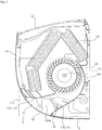
- FIG. 2 is a side cross-sectional view of an air conditioner according to an embodiment of the present invention.
- An air conditioner 1 includes an exterior appearance of an air conditioner, a housing 10 forming an air inlet 22 and an air outlet 24, a heat exchanger 28 for heating or cooling air flowing inside the housing 10, a blowing fan 26 for allowing air inside the housing 10 to flow toward the air outlet 24, and a discharge guide 100 for guiding air, flowing by the blowing fan 26, toward the air outlet 24.
- the housing 10 may form the air inlet 22 through which air is suctioned from above an upper surface 12 or a front surface 16, and may form the air outlet 24 through which air is discharged from below the front surface 16.
- the housing 10 may have a rectangular shape that elongates in a left-right direction.
- the air conditioner according to the present embodiment relates to an indoor unit for a wall air conditioner, and the air outlet 24 may be formed below the air inlet 22 so that air can flow from an upper side to a lower side inside the housing 10.
- the air inlet 22 may be disposed above the center of the blowing fan 26, and the air outlet 24 may be disposed below the center of the blowing fan 26.
- An outer circumferential surface of the housing 10 may include a rear surface 18 disposed to face an indoor wall surface, an upper surface 12 having the air inlet 22 formed therein, the front surface 16 formed in a direction opposite to the rear surface 18, a lower surface 14 formed in a direction opposite to the upper surface 12, and both side surfaces 20a and 20b forming surfaces vertical to the front surface 16, the rear surface 18, the upper surface 12, and the lower surface 14.
- the front surface 16 and the lower surface 14 are gently continued in a curved surface shape, and the air outlet 24 is formed at a portion where the front surface 16 and the lower surface 14 are continued in the curved surface shape.
- the air outlet 24 according to the present embodiment may be formed in a front lower portion of the housing 10.
- the housing 10 forms an interior space where the heat exchanger 28 and the blowing fan 26 are disposed.
- a guide for guiding air suctioned through the air inlet 22 toward the blowing fan 26 or for guiding air flowing in the blowing fan 26 toward the air outlet 24 may be formed.
- a discharge guide 100 for guiding air flowing in the blowing fan 26 toward the air outlet 24 may be formed. Configuration and shape of the discharge guide 100 will be described later on in more detail.
- the blowing fan 26 causes air introduced into the housing 10 through the air inlet 22 to flow toward the air outlet 24.
- the blowing fan 26 may be a cross flow fan, which suctions and discharges air in a direction vertical to a rotational axis direction of the blowing fan 26.
- a center 26c of the blowing fan 26 is disposed below the air inlet 22.
- the center 26c of the blowing fan 26 may be disposed above the air outlet 24.
- the blowing fan 26 may be disposed below the heat exchanger 28 to make air introduced into the housing 10 through the air inlet 22 and heat-exchanged with the heat exchanger 28 flow toward the air outlet 24.
- the air conditioner 1 may further include a blowing fan motor (not shown) disposed in one side of the blowing fan 26 and rotating the blowing fan 26.
- a blowing fan motor (not shown) disposed in one side of the blowing fan 26 and rotating the blowing fan 26.
- the heat exchanger 28 may perform heat exchange with air flowing in the housing 10 to cool or heat the air.
- the heat exchanger 28 may perform heat exchange with air flowing in the housing 10, by condensing or evaporating a refrigerant flowing in the heat exchanger 28.
- the heat exchanger 28 may be disposed between the blowing fan 26 and the air inlet 22 and performing heat exchange of outdoor air introduced through the air inlet 22. According to the present embodiment, the heat exchanger 28 may be disposed in a direction in which outdoor air is allowed to be introduced from above the blowing fan 26 and flow toward the blowing fan 26.
- the air conditioner 1 may further include a vane disposed in the air outlet 24 or in a discharge flow path 100a to guide a wind direction of discharged air.
- the vane may include a horizontal vane 30 for controlling a wind direction of discharged air in an upward-downward direction, and a vertical vane 32 for controlling a wind direction of discharged air in a left-right direction.
- the horizontal vane 30 is disposed at the air outlet 24 which is an end of the discharge flow path 100a, and the vertical vane 32 may be disposed at a position deeper inside the housing 10 than the horizontal vane 30.
- the horizontal vane 30 may be rotatably connected to a vane fixing rib 134 protruding from an upper guide 120, which will be described later on, in a direction toward the discharge flow path.
- the vertical vane 32 may be rotatably connected to one side of a lower guide 110 which will be described later on.
- FIG. 3 is an enlarged cross-sectional view of a portion A shown in FIG. 2 .
- FIG. 4 is a cross-sectional view of an upper guide according to an embodiment of the present invention.
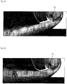
- FIG. 5 is a view for explaining a difference of a wind direction of air due to the presence of an upper guide-curved surface portion of the present invention, wherein FIG. 5A shows a wind direction of air discharged from an upper guide having no upper guide-curved surface portion and FIG. 5B shows a wind direction of air discharged from an upper guide having an upper guide-curved surface portion.
- FIG. 6 is a perspective view of a part of an upper guide, including a distance maintaining member and a vane fixing rib, according to an embodiment of the present invention.
- FIG. 7 is a perspective view of a part of an upper guide, having a plurality of protrusions and a plurality of grooves, according to an embodiment of the present invention.
- FIG. 8 is for explaining a difference in flow separation occurring because an upper guide of the present invention has grooves, wherein FIG. 8A shows an air flow in an upper guide having no groove and FIG. 8B shows an air flow in an upper guide having grooves formed therein.
- FIG. 9 is a diagram for explaining a relationship between protrusions and grooves arranged in an upper guide according to an embodiment of the present invention.
- FIGS. 3 to 9 structure and shape of a discharge guide forming a discharge flow path of an air conditioner according to the present invention will be described.
- the air conditioner 1 includes a discharge guide 100 for guiding air flowing by the blowing fan 26 to ward the air outlet 24.
- the discharge guide 100 forms a discharge flow path 100a along which air flows by the blowing fan 26.
- the discharge guide 100 guides the air, flowing by the blowing fan 26, toward the air outlet 24.
- the discharge guide 100 may include an upper guide 120 disposed above the discharge flow path 100a, and the lower guide 110 disposed below the discharge flow path 100a.
- the upper guide 120 is connected from a portion in front of the center 26c of the blowing fan 26 to an upper end of the air outlet 24.
- the lower guide 110 is connected from a rear portion behind the center 26c of the blowing fan 26 to a lower end of the air outlet 24.
- the lower guide 110 includes a lower guide-curved surface portion 112, which is formed in a curved surface portion to guide air discharged by the blowing fan 26 from a rear side of the blowing fan 26 or a lower side of the blowing fan 26 toward the air outlet 24, and a lower guide-straight surface portion 114 which is formed in a straight surface portion extending from the lower guide-curved surface portion 112 toward the air outlet 24.
- the lower guide-curved surface portion 112 may extend forming a curved surface portion from a partition portion 116 that is disposed the most adjacent to the center 26c of the blowing fan 26 toward a lower side.
- the partition portion 116 of the lower guide 110 disposed the most adjacent to the center 26c of the blowing fan 26 may be formed over a rear upper side of the blowing fan 26.
- a portion of the lower guide-curved surface portion 112 from the partition portion 116 toward the air outlet 24 is formed to be gradually spaced apart from the center 26c of the blowing fan 26. That is, a radius of curvature of the lower guide-curved surface portion 112 is formed to be greater than a radius of curvature of the blowing fan 26.
- the lower guide-curved surface portion 112 may extend to a lower rear side of the blowing fan 26. Air flowing by the blowing fan 26 may be reflected by the lower guide-curved surface portion 112 and then flow toward the upper guide 120.
- the lower guide-straight surface portion 114 may seamlessly extend from the lower guide-curved surface portion 112. Accordingly, the lower guide-straight surface portion 114 may extend at an angle of inclination formed by the end of the lower guide-curved surface portion 112. The lower guide-straight surface portion 114 may form an angle of inclination in such a way that the end of the lower guide-straight surface portion 114 faces a front lower side.
- the lower guide 110 may include a lower guide-upper end 118 extending upward from the partition portion 116 disposed the most adjacent to the center 26c of the blowing fan 26.
- the lower guide-upper end 118 may extend toward above the blowing fan 26, and guide air to be suctioned into the blowing fan 26.
- the upper guide 120 forms the discharge flow path 100a with the lower guide 110, and the upper guide 120 is disposed to face the lower guide 110.
- the upper guide 120 includes an upper guide-straight surface portion 122, forming a straight surface portion at an upper stream side of the discharge flow path 100a, and an upper guide-curved surface portion 124, extending from the upper guide-straight surface portion 122 toward the air outlet 24 and forming a curved surface portion convex toward the air outlet 24.
- the upper guide-straight surface portion 122 may form the discharge flow path 100a with the lower guide-straight surface portion.
- An angle ⁇ 1 of inclination between the upper guide-straight surface portion 122 and a virtual horizontal line formed in a front-back direction is smaller than an angle ⁇ 2 of inclination between the lower guide-straight surface portion 114 and the virtual horizontal line.
- the upper guide-straight surface portion 122 is elongated in a direction in which air flows.
- a plurality of grooves 130 forming recessed portions inwardly of the upper guide-straight surface portion 122 may be formed.
- the plurality of grooves 130 may be arranged at a predetermined interval from each other in an axial direction of the blowing fan 26.
- the plurality of grooves 130 may suppress flow separation that occurs by air flowing along the upper guide-straight surface portion 122. That is, it is possible to minimize an increase of flow friction caused by an increased flow rate of air flowing along the upper guide-straight surface portion 122.
- the plurality of grooves 130 may be formed in a length L0 equal to or greater than half a length L3 formed by the upper guide-straight surface portion 122 along the discharge flow path 100a.
- a depth 130h of recessed portions formed inwardly of the upper guide-straight surface portion 122 by the plurality of grooves 130 may be maintained constant along the length of a corresponding groove.
- the depth 130h may be formed to increase or decrease in a direction in which air flows.
- the upper guide-straight surface portion 122 may further include a plurality of protrusions 132 arranged along an axial direction of the blowing fan 26.
- the plurality of protrusions 132 may protrude downward from a surface of the upper guide-straight surface portion 122 facing toward the lower guide 110.
- the plurality of protrusions 132 may suppress a vortex occurring in air that flows along the discharge flow path 100a.
- the plurality of protrusions 132 may be disposed at an upper stream side than the plurality of grooves 130.
- the plurality of protrusions 132 may be disposed more adjacent to the blowing fan 26 than the plurality of grooves 130.
- air flowing in the discharge flow path 100a by the blowing fan 26 may flow to the plurality of grooves 130 after passing through the plurality of protrusions 132.
- an interval 132d between adjacent protrusions among the plurality of protrusions 132 is greater than an interval 130d between adjacent grooves among the plurality of grooves 130.
- two grooves 130 are arranged between two protrusions adjacent to the axial direction of the blowing fan 26.
- a height 132h by which the protrusions 132 protrude from the upper guide-straight surface portion 122 is greater than a depth 130h of recessed portions formed inwardly of the upper guide-straight surface portion 122 by the grooves 130.
- the upper guide-curved surface portion 124 extends from the upper guide-straight surface portion 122 toward the air outlet 24, and forms a curved surface portion convex in a direction toward the air outlet 24.
- an inclined surface formed by an upstream end 124a of the upper guide-curved surface portion 124 is formed to be inclined further below than a virtual horizontal line formed in a front-back direction, and an inclined surface formed by a downstream end 124b is formed to be parallel to the virtual horizontal line or inclined further above than the horizontal line.
- the end 124b of the upper guide-curved surface portion 124 disposed being adjacent to the air outlet 24 may be formed to be inclined upwardly than the virtual horizontal line or may form an inclined surface in the same direction as that of the virtual horizontal line.
- an extension degree of a cross section of the discharge flow path 100a formed between the upper guide-curved surface portion 124 and the lower guide-straight surface portion 114 is greater than an extension degree of the discharge flow path 100a formed between the upper guide straight surface portion 122 and the lower guide-straight surface portion 114.
- the curved surface structure formed by the upper guide-curved surface 124 may improve pressure recovery of the air outlet 24 and thereby increase an amount of air flow.
- the upper guide-curved surface portion 124 may form an upward wind direction so that air can be upwardly discharged through the air outlet 24. That is, due to the Coanda effect, air flowing along the upper guide-straight surface portion 122 flows along a surface formed by the upper-guide curved surface portion 124, and therefore, a discharge direction may be formed upwardly. Thus, as a wind direction of air to be discharged from the air outlet 24 is formed upwardly, the upper guide-curved surface portion 124 can discharge air from the air conditioner 1 by a long distance.
- the upper guide 120 includes an upper guide-upper end 126 guiding a part of the air discharged from the blowing fan 26 toward the blowing fan 26 again, and a connecting portion 128 connecting the upper guide-upper end 126 and the upper guide-straight surface portion 122.
- the upper guide-upper end 126 extends to be closer toward the center of the blowing fan 26 along an outer circumferential surface of the blowing fan 26.
- the upper guide-upper end 126 is disposed as closer as possible to the blowing fan 26 in such a way to minimize an amount of air flow that is discharged from the blowing fan 26 and then flows in reverse back to the blowing fan 26.
- An angle between the upper guide-upper end 126 and the upper guide-straight surface portion 122 may form an acute angle smaller than a right angle.
- the connecting portion 128 may gently bend in such a way to minimize a vortex of air discharged from the blowing fan 26, which occurs between the discharge flow path 100a and a reverse flow path 102a.
- the upper guide 120 may be spaced apart from an upper end of the air outlet 24 at a predetermined interval, and the upper guide 120 may further include an extension guide 140 that connects the upper end of the air outlet 24 and the upper guide 120.
- the extension guide 140 may maintain an extension degree of a cross section of the discharge flow path 100a extended by the upper guide-curved surface portion 124.
- the extension guide 140 connects the downstream end 124b of the upper guide-curved surface portion 124 and the upper end of the air outlet 25.
- the extension guide 140 may form a straight surface along the discharge flow path 100a.
- the extension guide 140 may maintain an inclined surface formed upwardly along the upper guide-curved surface portion 124.
- grooves and protrusions may be formed even in the extension guide 140 to increase an amount of air to be discharged through the air outlet 24.
- the upper guide 120 may further include an interval maintaining member 136 for maintaining an interval between the upper guide 120 and the lower guide 110, and the vane fixing rib 134 for rotatably fixing the horizontal vane 30.
- the interval maintaining member 136 may protrude from the upper guide 120 toward the discharge flow path 100a and be connected to the lower guide 110. In the interval maintaining member 136, a plurality of damping grooves may be formed to alleviate vibration occurring due to rotation of the blowing fan 26 disposed above the upper guide 120 in the housing 10.
- the vane fixing rib 134 may protrude from the upper guide 120 toward the air outlet 24, and may be rotatably fixed to the horizontal vane 30 at an end thereof.
- the interval maintaining member 136 and the vane fixing rib 134 may be provided in plural at a predetermined interval along the rotational axis direction of the blowing fan 26.
- a plurality of protrusions and a plurality of grooves may be formed between the plurality of interval maintaining members 136 and a plurality of vane fixing ribs 134.
- FIG. 10 is a diagram showing a relationship between arrangement of protrusions and an upper guide of an air conditioner according to the present invention and an amount of air discharged through an air outlet.
- FIG. 11 is a diagram showing a relationship between arrangement of a start potion of a groove in an air conditioner according to an embodiment and an amount of air discharged through an air outlet.
- FIG. 12 is a diagram showing a relationship between arrangement of a finish end of a groove in an air conditioner according to an embodiment and an amount of air discharged through an air outlet.
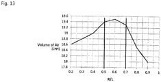
- FIG. 13 is a diagram showing an amount of air to be discharged through an air outlet depending on a relationship between a length of an upper guide and a radius of curvature of an upper guide-curved surface portion according to an embodiment of the present invention.
- the protrusions 132 may be spaced apart at a predetermined interval from the upstream end 120a of the upper guide 120 by taking into consideration the following: shape and arrangement of the upper guide-upper end 126 and the connecting portion 128 and occurrence of a vortex of air flowing along the upstream of the upper guide-straight surface portion 122.
- the length L of the upper guide 120 may be defined as a distance from the upstream end 120a to the downstream end 120b of a line formed along the upper guide-straight surface portion 122.
- the plurality of protrusions 132 may be spaced apart at a first preset interval L1 from the upstream end 120a of the upper guide 120.
- the first preset interval L1 may be greater than 0.09 times of the length L of the upper guide 120 and smaller than 0.15 times of the length L of the upper guide 120.
- Arrangement of the grooves 130 in the upper guide-straight surface portion 122 may be set by taking into consideration the following: a length of the upper guide-straight surface portion 122 and a timing of when flow separation occurs in air flowing along the upper guide 120.
- the second preset interval L2 may be greater than 0115 times of the length L of the upper guide 120 and smaller than 0.2 times of the length L of the upper guide 120.
- the third preset interval L3 may be greater than 0.55 times of the length L of the upper guide and smaller than 0.7 times of the length L of the upper guide 120.
- a radius R of curvature formed by the upper guide-curved surface portion 124 may be set by taking into consideration the following: a structure where a wind direction can be set to cause discharged air to flow upwardly, and a range where air flowing along the upper guide-curved surface portion 124 can have the Coanda effect.
- an amount of discharged air flow reaches a predetermined level or higher.
- the radius R of a curvature structure formed by the upper guide-curved surface portion 124 is preferably greater than 0.5 of the length L of the upper guide 120 and smaller than 0.7 times of the length L of the upper guide 120.
Landscapes
- Engineering & Computer Science (AREA)
- Chemical & Material Sciences (AREA)
- Combustion & Propulsion (AREA)
- Mechanical Engineering (AREA)
- General Engineering & Computer Science (AREA)
- Physics & Mathematics (AREA)
- Thermal Sciences (AREA)
- Air-Conditioning Room Units, And Self-Contained Units In General (AREA)
- Air-Flow Control Members (AREA)
Abstract
Description
- The present invention relates to an air conditioner.
- An air conditioner includes a compressor for compressing a refrigerant, a condenser for condensing the compressed refrigerant, an expander for expanding the condensed refrigerant, and an evaporator for evaporating the expanded refrigerant. The air conditioner is a device that heats or cools indoor air by causing a refrigerant to flow using the aforementioned elements, so that the indoor air can be controlled to a proper temperature.
- The air conditioner may include an indoor unit having a heat exchanger to perform heat exchange of indoor unit, and an outdoor unit having a heat exchanger for performing heat exchange of outdoor air. The heat exchangers provided in the indoor unit and the outdoor unit may serve as an evaporator or a condenser according to circulation of a refrigerant.
- The indoor unit may be classified into a ceiling-mount type, a stand alone type, and a wall-mount type according to arrangement and structure. The wall-mount indoor unit is disposed on an upper side of an indoor wall surface, and has an air outlet formed therein to discharge heat-exchanged air toward a front lower side.
- In the wall-mount indoor unit, a discharge flow path is formed toward a front lower side so as to guide air flowing in a blowing fan formed in a rear upper side of an air outlet, and therefore, it is difficult to discharge air by a long distance or discharge air upwardly by a long distance, by using a wind direction of discharged air and a volume of air discharged by a vortex occurring in a discharge flow path.
- Korean Patent Application Publication No.
10-2018-0010888 - In addition, in a structure having the above-described discharge flow path, when a vane forming a horizontal wind is disposed parallel to a floor or a ceiling surface, the discharge flow path is reduced in a cross-sectional area toward a downstream thereof, and a volume of air to be discharged through the air outlet is reduced.
- The air conditioner having the aforementioned structure have difficulties in discharging a large volume of air by a long distance, and thus, a cooling operation cannot be efficiently performed by an indoor unit placed in a large space.
- An object of the present invention is to provide an air conditioner capable of discharging air by a long distance.
- Yet another object of the present invention is to provide an air conditioner capable of ensuring a predetermined or more volume of discharged air.
- These objects are achieved with the features of the independent claims. Preferred embodiments are defined in the dependent claims.
- In order to achieve the above objects, there is provided an air conditioner including: a housing forming an air inlet and an air outlet disposed below the air inlet; a blowing fan disposed below the air inlet and in an upper rear side of the air outlet, and rotating about a rotational axis formed in a left-right direction so that air suctioned through the air inlet flows toward the air outlet; a lower guide guiding air, discharged to a rear side and a lower side of the blowing fan, toward the air outlet; and an upper guide disposed above the lower discharge guide to form a discharge flow path with the lower guide in such a way that a cross section of the discharge flow path from the blowing fan to the air outlet is extended gradually toward the air outlet, wherein the upper guide forms a curved surface at an end adjacent to the air outlet, the surface which is convex in a direction toward the air outlet.
- The lower guide may include: a lower guide-curved surface portion formed in a curved surface to guide air, discharged by the blowing fan toward the rear side or the lower side of the blowing fan, toward the air outlet; and a lower guide-straight surface portion extending and forming a straight surface from the lower guide-curved surface portion toward the air outlet.
- The upper guide may include: an upper guide-straight surface portion forming a straight surface at an upstream side of the discharge flow path; and an upper guide-curved surface portion extending from the upper guide-straight surface portion toward the air outlet and forming a curved surface convex in a direction toward the air outlet.
- An angle of inclination between the lower guide-straight surface portion and a virtual horizontal line formed in a front-back direction may be greater than an angle of inclination between the upper guide-straight surface portion and the horizontal line.
- A direction facing an end of the upper guide-curved surface portion adjacent to the air outlet may be formed higher than a virtual horizontal surface formed in a front-back direction.
- The upper guides may include a plurality of protrusions formed at an upstream of the upper guide to vertically protrude from a surface formed by the upper guide, and spaced apart from each other in a rotational axis direction of the blowing fan.
- The upper guide may include a plurality of grooves elongated in a direction in which air flows along the discharge flow path, and forming recessed portions inwardly of the upper guide.
- The plurality of grooves may be disposed at a downstream side of the plurality of protrusions in a direction in which air flows from the upper guide.
- A height by which the protrusions protrude from the upper guide may be greater than a depth of recessed portion formed inwardly of the upper guide by the grooves.
- Two grooves may be arranged between two adjacent protrusions among the plurality of protrusions.
- The upper guide may include: an upper guide-straight surface portion forming a straight surface at an upstream of the discharge flow path; and an upper guide-curved surface portion forming a curved surface convex in a direction toward the air outlet.
- The protrusions and the grooves may be disposed in the upper guide-straight surface portion.
- The plurality of grooves may be formed in a length equal to or greater than half a length in which the upper guide-straight surface portion is formed vertically with respect to a rotational axis of the blowing fan.
- The upper guide and the air outlet may be spaced apart from each other.
- The air conditioner may further include an extension guide that connects a downstream end of the upper guide-curved surface portion and an upper end of the air outlet.
- The details of other embodiments are included in the following description and the accompanying drawings.
- According to the air conditioner of the present invention, there are one or more effects as below.
- First, as air is discharged through an upper side along an upper guide due to the Coanda effect at a downstream of the discharge flow path, there is an advantageous effect that air can be discharged by a long distance.
- Second, as a cross section of the discharge flow path increases toward the downstream, even though a vane is not formed horizontally at the air outlet, a cross section of the discharge flow path is not greatly decreased, and therefore, it is possible to secure a predetermined amount of air flow to be discharged through the air outlet.
- Effects of the present invention should not be limited to the aforementioned effects and other unmentioned effects will be clearly understood by those skilled in the art from the claims.
- The embodiments will be described in detail with reference to the following drawings in which like reference numerals refer to like elements wherein:
-
FIG. 1 is a perspective view of an air conditioner according to an embodiment of the present invention; -
FIG. 2 is a side cross-sectional view of an air conditioner according to an embodiment of the present invention; -
FIG. 3 is an enlarged cross-sectional view of a portion A shown inFIG. 2 ; -
FIG. 4 is a cross-sectional view of an upper guide according to an embodiment of the present invention; -
FIG. 5 is a view for explaining a difference of a wind direction of air due to the presence of an upper guide-curved surface portion of the present invention, whereinFIG. 5A shows a wind direction of air discharged from an upper guide having no upper guide-curved surface portion andFIG. 5B shows a wind direction of air discharged from an upper guide having an upper guide-curved surface portion; -
FIG. 6 is a perspective view of a part of an upper guide, including a distance maintaining member and a vane fixing rib, according to an embodiment of the present invention; -
FIG. 7 is a perspective view of a part of an upper guide, having a plurality of protrusions and a plurality of grooves, according to an embodiment of the present invention; -
FIG. 8 is for explaining a difference in flow separation occurring because an upper guide of the present invention has grooves, whereinFIG. 8A shows an air flow in an upper guide having no groove andFIG. 8B shows an air flow in an upper guide having grooves formed therein; -
FIG. 9 is a diagram for explaining a relationship between protrusions and grooves arranged in an upper guide according to an embodiment of the present invention; -
FIG. 10 is a diagram showing a relationship between arrangement of protrusions and an upper guide of an air conditioner according to the present invention and an amount of air discharged through an air outlet; -
FIG. 11 is a diagram showing a relationship between arrangement of a start potion of a groove in an air conditioner according to an embodiment and an amount of air discharged through an air outlet; -
FIG. 12 is a diagram showing a relationship between arrangement of a finish end of a groove in an air conditioner according to an embodiment and an amount of air discharged through an air outlet; and -
FIG. 13 is a diagram showing an amount of air to be discharged through an air outlet depending on a relationship between a length of an upper guide and a radius of curvature of an upper guide-curved surface portion according to an embodiment of the present invention. - Advantages and features of the present invention and a method of achieving the same will be clearly understood from embodiments described below in detail with reference to the accompanying drawings. However, the present invention is not limited to the following embodiments and may be implemented in various different forms. The embodiments are provided merely for complete disclosure of the present invention and to fully convey the scope of the invention to those of ordinary skill in the art to which the present invention pertains. The present invention is defined only by the scope of the claims. In the drawings, the thickness of layers and regions may be exaggerated for clarity. Throughout the drawings, like numbers refer to like elements.
- Hereinafter, an air conditioner according to embodiments of the present invention will be described with reference to the accompanying drawings.
-
FIG. 1 is a perspective view of an air conditioner according to an embodiment of the present invention, andFIG. 2 is a side cross-sectional view of an air conditioner according to an embodiment of the present invention. - Hereinafter, overall configuration of an air conditioner according to the present embodiment will be described with reference to
FIGS. 1 and2 . - An
air conditioner 1 according to an embodiment of the present invention includes an exterior appearance of an air conditioner, ahousing 10 forming anair inlet 22 and anair outlet 24, aheat exchanger 28 for heating or cooling air flowing inside thehousing 10, a blowingfan 26 for allowing air inside thehousing 10 to flow toward theair outlet 24, and a discharge guide 100 for guiding air, flowing by the blowingfan 26, toward theair outlet 24. - The
housing 10 may form theair inlet 22 through which air is suctioned from above anupper surface 12 or afront surface 16, and may form theair outlet 24 through which air is discharged from below thefront surface 16. Thehousing 10 may have a rectangular shape that elongates in a left-right direction. - The air conditioner according to the present embodiment relates to an indoor unit for a wall air conditioner, and the
air outlet 24 may be formed below theair inlet 22 so that air can flow from an upper side to a lower side inside thehousing 10. According to the present embodiment, theair inlet 22 may be disposed above the center of the blowingfan 26, and theair outlet 24 may be disposed below the center of the blowingfan 26. - An outer circumferential surface of the
housing 10 according to the present embodiment may include arear surface 18 disposed to face an indoor wall surface, anupper surface 12 having theair inlet 22 formed therein, thefront surface 16 formed in a direction opposite to therear surface 18, alower surface 14 formed in a direction opposite to theupper surface 12, and bothside surfaces front surface 16, therear surface 18, theupper surface 12, and thelower surface 14. - According to the present embodiment, the
front surface 16 and thelower surface 14 are gently continued in a curved surface shape, and theair outlet 24 is formed at a portion where thefront surface 16 and thelower surface 14 are continued in the curved surface shape. Theair outlet 24 according to the present embodiment may be formed in a front lower portion of thehousing 10. - The
housing 10 forms an interior space where theheat exchanger 28 and the blowingfan 26 are disposed. Within thehousing 10, a guide for guiding air suctioned through theair inlet 22 toward the blowingfan 26 or for guiding air flowing in the blowingfan 26 toward theair outlet 24 may be formed. Within thehousing 10, a discharge guide 100 for guiding air flowing in the blowingfan 26 toward theair outlet 24 may be formed. Configuration and shape of the discharge guide 100 will be described later on in more detail. - The blowing
fan 26 causes air introduced into thehousing 10 through theair inlet 22 to flow toward theair outlet 24. According to the present embodiment, the blowingfan 26 may be a cross flow fan, which suctions and discharges air in a direction vertical to a rotational axis direction of the blowingfan 26. - A
center 26c of the blowingfan 26 is disposed below theair inlet 22. Thecenter 26c of the blowingfan 26 may be disposed above theair outlet 24. - According to the present embodiment, the blowing
fan 26 may be disposed below theheat exchanger 28 to make air introduced into thehousing 10 through theair inlet 22 and heat-exchanged with theheat exchanger 28 flow toward theair outlet 24. - The
air conditioner 1 according to the present embodiment may further include a blowing fan motor (not shown) disposed in one side of the blowingfan 26 and rotating the blowingfan 26. - The
heat exchanger 28 may perform heat exchange with air flowing in thehousing 10 to cool or heat the air. Theheat exchanger 28 may perform heat exchange with air flowing in thehousing 10, by condensing or evaporating a refrigerant flowing in theheat exchanger 28. - According to the present embodiment, the
heat exchanger 28 may be disposed between the blowingfan 26 and theair inlet 22 and performing heat exchange of outdoor air introduced through theair inlet 22. According to the present embodiment, theheat exchanger 28 may be disposed in a direction in which outdoor air is allowed to be introduced from above the blowingfan 26 and flow toward the blowingfan 26. - According to the present embodiment, the
air conditioner 1 may further include a vane disposed in theair outlet 24 or in adischarge flow path 100a to guide a wind direction of discharged air. - According to the present embodiment, the vane may include a
horizontal vane 30 for controlling a wind direction of discharged air in an upward-downward direction, and avertical vane 32 for controlling a wind direction of discharged air in a left-right direction. - According to the present embodiment, the
horizontal vane 30 is disposed at theair outlet 24 which is an end of thedischarge flow path 100a, and thevertical vane 32 may be disposed at a position deeper inside thehousing 10 than thehorizontal vane 30. - The
horizontal vane 30 may be rotatably connected to avane fixing rib 134 protruding from an upper guide 120, which will be described later on, in a direction toward the discharge flow path. Thevertical vane 32 may be rotatably connected to one side of a lower guide 110 which will be described later on. -
FIG. 3 is an enlarged cross-sectional view of a portion A shown inFIG. 2 .FIG. 4 is a cross-sectional view of an upper guide according to an embodiment of the present invention.FIG. 5 is a view for explaining a difference of a wind direction of air due to the presence of an upper guide-curved surface portion of the present invention, whereinFIG. 5A shows a wind direction of air discharged from an upper guide having no upper guide-curved surface portion andFIG. 5B shows a wind direction of air discharged from an upper guide having an upper guide-curved surface portion.FIG. 6 is a perspective view of a part of an upper guide, including a distance maintaining member and a vane fixing rib, according to an embodiment of the present invention.FIG. 7 is a perspective view of a part of an upper guide, having a plurality of protrusions and a plurality of grooves, according to an embodiment of the present invention.FIG. 8 is for explaining a difference in flow separation occurring because an upper guide of the present invention has grooves, whereinFIG. 8A shows an air flow in an upper guide having no groove andFIG. 8B shows an air flow in an upper guide having grooves formed therein.FIG. 9 is a diagram for explaining a relationship between protrusions and grooves arranged in an upper guide according to an embodiment of the present invention. - Hereinafter, referring to
FIGS. 3 to 9 , structure and shape of a discharge guide forming a discharge flow path of an air conditioner according to the present invention will be described. - The
air conditioner 1 according to the present embodiment includes a discharge guide 100 for guiding air flowing by the blowingfan 26 to ward theair outlet 24. According to the present embodiment, the discharge guide 100 forms adischarge flow path 100a along which air flows by the blowingfan 26. The discharge guide 100 guides the air, flowing by the blowingfan 26, toward theair outlet 24. - According to the present embodiment, the discharge guide 100 may include an upper guide 120 disposed above the
discharge flow path 100a, and the lower guide 110 disposed below thedischarge flow path 100a. The upper guide 120 is connected from a portion in front of thecenter 26c of the blowingfan 26 to an upper end of theair outlet 24. The lower guide 110 is connected from a rear portion behind thecenter 26c of the blowingfan 26 to a lower end of theair outlet 24. - The lower guide 110 includes a lower guide-
curved surface portion 112, which is formed in a curved surface portion to guide air discharged by the blowingfan 26 from a rear side of the blowingfan 26 or a lower side of the blowingfan 26 toward theair outlet 24, and a lower guide-straight surface portion 114 which is formed in a straight surface portion extending from the lower guide-curved surface portion 112 toward theair outlet 24. - The lower guide-
curved surface portion 112 may extend forming a curved surface portion from apartition portion 116 that is disposed the most adjacent to thecenter 26c of the blowingfan 26 toward a lower side. Thepartition portion 116 of the lower guide 110 disposed the most adjacent to thecenter 26c of the blowingfan 26 may be formed over a rear upper side of the blowingfan 26. - A portion of the lower guide-
curved surface portion 112 from thepartition portion 116 toward theair outlet 24 is formed to be gradually spaced apart from thecenter 26c of the blowingfan 26. That is, a radius of curvature of the lower guide-curved surface portion 112 is formed to be greater than a radius of curvature of the blowingfan 26. According to the present invention, the lower guide-curved surface portion 112 may extend to a lower rear side of the blowingfan 26. Air flowing by the blowingfan 26 may be reflected by the lower guide-curved surface portion 112 and then flow toward the upper guide 120. - The lower guide-
straight surface portion 114 may seamlessly extend from the lower guide-curved surface portion 112. Accordingly, the lower guide-straight surface portion 114 may extend at an angle of inclination formed by the end of the lower guide-curved surface portion 112. The lower guide-straight surface portion 114 may form an angle of inclination in such a way that the end of the lower guide-straight surface portion 114 faces a front lower side. - The lower guide 110 may include a lower guide-
upper end 118 extending upward from thepartition portion 116 disposed the most adjacent to thecenter 26c of the blowingfan 26. The lower guide-upper end 118 may extend toward above the blowingfan 26, and guide air to be suctioned into the blowingfan 26. - The upper guide 120 forms the
discharge flow path 100a with the lower guide 110, and the upper guide 120 is disposed to face the lower guide 110. The upper guide 120 includes an upper guide-straight surface portion 122, forming a straight surface portion at an upper stream side of thedischarge flow path 100a, and an upper guide-curved surface portion 124, extending from the upper guide-straight surface portion 122 toward theair outlet 24 and forming a curved surface portion convex toward theair outlet 24. - According to the present embodiment, the upper guide-
straight surface portion 122 may form thedischarge flow path 100a with the lower guide-straight surface portion. An angle θ1 of inclination between the upper guide-straight surface portion 122 and a virtual horizontal line formed in a front-back direction is smaller than an angle θ2 of inclination between the lower guide-straight surface portion 114 and the virtual horizontal line. - According to the present embodiment, the upper guide-
straight surface portion 122 is elongated in a direction in which air flows. A plurality ofgrooves 130 forming recessed portions inwardly of the upper guide-straight surface portion 122 may be formed. The plurality ofgrooves 130 may be arranged at a predetermined interval from each other in an axial direction of the blowingfan 26. - The plurality of
grooves 130 may suppress flow separation that occurs by air flowing along the upper guide-straight surface portion 122. That is, it is possible to minimize an increase of flow friction caused by an increased flow rate of air flowing along the upper guide-straight surface portion 122. - The plurality of
grooves 130 may be formed in a length L0 equal to or greater than half a length L3 formed by the upper guide-straight surface portion 122 along thedischarge flow path 100a. Adepth 130h of recessed portions formed inwardly of the upper guide-straight surface portion 122 by the plurality ofgrooves 130 may be maintained constant along the length of a corresponding groove. In another embodiment, thedepth 130h may be formed to increase or decrease in a direction in which air flows. - According to the present embodiment, the upper guide-
straight surface portion 122 may further include a plurality ofprotrusions 132 arranged along an axial direction of the blowingfan 26. The plurality ofprotrusions 132 may protrude downward from a surface of the upper guide-straight surface portion 122 facing toward the lower guide 110. The plurality ofprotrusions 132 may suppress a vortex occurring in air that flows along thedischarge flow path 100a. - In the upper guide-
straight surface portion 122, the plurality ofprotrusions 132 may be disposed at an upper stream side than the plurality ofgrooves 130. The plurality ofprotrusions 132 may be disposed more adjacent to the blowingfan 26 than the plurality ofgrooves 130. Thus, air flowing in thedischarge flow path 100a by the blowingfan 26 may flow to the plurality ofgrooves 130 after passing through the plurality ofprotrusions 132. - According to the present embodiment, an interval 132d between adjacent protrusions among the plurality of
protrusions 132 is greater than an interval 130d between adjacent grooves among the plurality ofgrooves 130. According to the present embodiment, twogrooves 130 are arranged between two protrusions adjacent to the axial direction of the blowingfan 26. According to the present embodiment, aheight 132h by which theprotrusions 132 protrude from the upper guide-straight surface portion 122 is greater than adepth 130h of recessed portions formed inwardly of the upper guide-straight surface portion 122 by thegrooves 130. - The upper guide-
curved surface portion 124 extends from the upper guide-straight surface portion 122 toward theair outlet 24, and forms a curved surface portion convex in a direction toward theair outlet 24. According to the present embodiment, an inclined surface formed by anupstream end 124a of the upper guide-curved surface portion 124 is formed to be inclined further below than a virtual horizontal line formed in a front-back direction, and an inclined surface formed by adownstream end 124b is formed to be parallel to the virtual horizontal line or inclined further above than the horizontal line. Theend 124b of the upper guide-curved surface portion 124 disposed being adjacent to theair outlet 24 may be formed to be inclined upwardly than the virtual horizontal line or may form an inclined surface in the same direction as that of the virtual horizontal line. - Thus, an extension degree of a cross section of the
discharge flow path 100a formed between the upper guide-curved surface portion 124 and the lower guide-straight surface portion 114 is greater than an extension degree of thedischarge flow path 100a formed between the upper guidestraight surface portion 122 and the lower guide-straight surface portion 114. - The curved surface structure formed by the upper guide-
curved surface 124 may improve pressure recovery of theair outlet 24 and thereby increase an amount of air flow. - According to the present embodiment, the upper guide-
curved surface portion 124 may form an upward wind direction so that air can be upwardly discharged through theair outlet 24. That is, due to the Coanda effect, air flowing along the upper guide-straight surface portion 122 flows along a surface formed by the upper-guidecurved surface portion 124, and therefore, a discharge direction may be formed upwardly. Thus, as a wind direction of air to be discharged from theair outlet 24 is formed upwardly, the upper guide-curved surface portion 124 can discharge air from theair conditioner 1 by a long distance. - According to the present embodiment, the upper guide 120 includes an upper guide-
upper end 126 guiding a part of the air discharged from the blowingfan 26 toward the blowingfan 26 again, and a connectingportion 128 connecting the upper guide-upper end 126 and the upper guide-straight surface portion 122. - The upper guide-
upper end 126 extends to be closer toward the center of the blowingfan 26 along an outer circumferential surface of the blowingfan 26. The upper guide-upper end 126 is disposed as closer as possible to the blowingfan 26 in such a way to minimize an amount of air flow that is discharged from the blowingfan 26 and then flows in reverse back to the blowingfan 26. An angle between the upper guide-upper end 126 and the upper guide-straight surface portion 122 may form an acute angle smaller than a right angle. The connectingportion 128 may gently bend in such a way to minimize a vortex of air discharged from the blowingfan 26, which occurs between thedischarge flow path 100a and areverse flow path 102a. - According to the present embodiment, the upper guide 120 may be spaced apart from an upper end of the
air outlet 24 at a predetermined interval, and the upper guide 120 may further include anextension guide 140 that connects the upper end of theair outlet 24 and the upper guide 120. Theextension guide 140 may maintain an extension degree of a cross section of thedischarge flow path 100a extended by the upper guide-curved surface portion 124. Theextension guide 140 connects thedownstream end 124b of the upper guide-curved surface portion 124 and the upper end of the air outlet 25. - The
extension guide 140 may form a straight surface along thedischarge flow path 100a. Theextension guide 140 may maintain an inclined surface formed upwardly along the upper guide-curved surface portion 124. - According to the present embodiment, grooves and protrusions may be formed even in the
extension guide 140 to increase an amount of air to be discharged through theair outlet 24. - According to the present embodiment, the upper guide 120 may further include an
interval maintaining member 136 for maintaining an interval between the upper guide 120 and the lower guide 110, and thevane fixing rib 134 for rotatably fixing thehorizontal vane 30. - The
interval maintaining member 136 may protrude from the upper guide 120 toward thedischarge flow path 100a and be connected to the lower guide 110. In theinterval maintaining member 136, a plurality of damping grooves may be formed to alleviate vibration occurring due to rotation of the blowingfan 26 disposed above the upper guide 120 in thehousing 10. - The
vane fixing rib 134 may protrude from the upper guide 120 toward theair outlet 24, and may be rotatably fixed to thehorizontal vane 30 at an end thereof. - According to the present embodiment, the
interval maintaining member 136 and thevane fixing rib 134 may be provided in plural at a predetermined interval along the rotational axis direction of the blowingfan 26. A plurality of protrusions and a plurality of grooves may be formed between the plurality ofinterval maintaining members 136 and a plurality ofvane fixing ribs 134. -
FIG. 10 is a diagram showing a relationship between arrangement of protrusions and an upper guide of an air conditioner according to the present invention and an amount of air discharged through an air outlet.FIG. 11 is a diagram showing a relationship between arrangement of a start potion of a groove in an air conditioner according to an embodiment and an amount of air discharged through an air outlet.FIG. 12 is a diagram showing a relationship between arrangement of a finish end of a groove in an air conditioner according to an embodiment and an amount of air discharged through an air outlet.FIG. 13 is a diagram showing an amount of air to be discharged through an air outlet depending on a relationship between a length of an upper guide and a radius of curvature of an upper guide-curved surface portion according to an embodiment of the present invention. - Hereinafter, a relationship of an upper guide's elements for increasing an amount of air to be discharged through an air outlet according to the present invention will be described with reference to
FIGS. 10 to 13 . - The
protrusions 132 may be spaced apart at a predetermined interval from theupstream end 120a of the upper guide 120 by taking into consideration the following: shape and arrangement of the upper guide-upper end 126 and the connectingportion 128 and occurrence of a vortex of air flowing along the upstream of the upper guide-straight surface portion 122. - Referring to
FIG. 10 , in a range where a first preset interval L1 is between 0.09 times and 0.15 times of a length L of the upper guide 120, an amount of discharged air flow reaches a predetermined level or higher. Here, the length L of the upper guide 120 may be defined as a distance from theupstream end 120a to thedownstream end 120b of a line formed along the upper guide-straight surface portion 122. - That is, the plurality of
protrusions 132 may be spaced apart at a first preset interval L1 from theupstream end 120a of the upper guide 120. The first preset interval L1 may be greater than 0.09 times of the length L of the upper guide 120 and smaller than 0.15 times of the length L of the upper guide 120. - Arrangement of the
grooves 130 in the upper guide-straight surface portion 122 may be set by taking into consideration the following: a length of the upper guide-straight surface portion 122 and a timing of when flow separation occurs in air flowing along the upper guide 120. - Referring to
FIG. 11 , in a range where a second preset interval L2 from theupstream end 120a of the upper guide 120 to the start end of thegroove 130 is between o.15 times and 0.2 times of the length L of the upper guide 120, an amount of discharged air flow reaches a predetermined level or higher. - Referring to
FIG. 12 , in a range where a third preset interval L3 between theupstream end 120a of the upper guide 120 and a finish end of thegroove 130 is between 0.55 times and 0.7 times of the length L of the upper guide 120, an amount of discharged air flow reaches a predetermined level or higher. - Accordingly, the second preset interval L2 may be greater than 0115 times of the length L of the upper guide 120 and smaller than 0.2 times of the length L of the upper guide 120. In addition, the third preset interval L3 may be greater than 0.55 times of the length L of the upper guide and smaller than 0.7 times of the length L of the upper guide 120.
- A radius R of curvature formed by the upper guide-
curved surface portion 124 may be set by taking into consideration the following: a structure where a wind direction can be set to cause discharged air to flow upwardly, and a range where air flowing along the upper guide-curved surface portion 124 can have the Coanda effect. - Referring to
FIG. 12 , in a range where the radius R of a curvature structure formed by the upper guide-curved surface portion 124 is between 0.5 times and 0.7 times of the length L of the upper guide 120, an amount of discharged air flow reaches a predetermined level or higher. - That is, the radius R of a curvature structure formed by the upper guide-
curved surface portion 124 is preferably greater than 0.5 of the length L of the upper guide 120 and smaller than 0.7 times of the length L of the upper guide 120. - Although the preferred embodiments of the present disclosure have been disclosed for illustrative purposes, those skilled in the art will appreciate that various modifications, additions and substitutions are possible, without departing from the scope and spirit of the disclosure as disclosed in the accompanying claims. Accordingly, such modifications, additions and substitutions should also be understood to fall within the scope of the present disclosure.
Claims (13)
- An air conditioner comprising:a housing (10) forming an air inlet (22) and an air outlet (24) disposed below the air inlet (22);a heat exchanger (28) for exchanging heat with a outside air introduced into the housing (10) through the air inlet (22) ;a blowing fan (26) disposed inside the housing (10) and in an upper rear side of the air outlet (24), and rotatable about a rotational axis formed in a left-right direction so that air suctioned through the air inlet (22) flows toward the air outlet (24);a lower guide (110) guiding air, discharged to a rear side and a lower side of the blowing fan (26), toward the air outlet(24); andan upper guide (120) disposed above the lower guide (110) to form a discharge flow path (100a) with the lower guide (110) in such a way that a cross section of the discharge flow path (100a) from the blowing fan (26) to the air outlet (24) is extended gradually toward the air outlet (24),wherein the upper guide (120) forms a curved surface at an end adjacent to the air outlet (24), the surface which is convex in a direction toward the air outlet (24).
- The air conditioner of claim 1,
wherein the lower guide (110) comprises:a lower guide-curved surface (112) portion formed in a curved surface to guide air, discharged by the blowing fan (26) toward the rear side or the lower side of the blowing fan (26), toward the air outlet (24); anda lower guide-straight surface (114) portion extending and forming a straight surface from the lower guide-curved surface (112) portion toward the air outlet (24). - The air conditioner of claim 1, or 2,
wherein the upper guide (120) comprises:an upper guide-straight surface portion (122) forming a straight surface at an upstream side of the discharge flow path (100a); andan upper guide-curved surface portion (124) extending from the upper guide-straight surface portion (122) toward the air outlet (24) and forming a curved surface convex in a direction toward the air outlet (24). - The air conditioner of claim 3, wherein an angle θ2 of inclination between the lower guide-straight surface portion (114) and a virtual horizontal line formed in a front-back direction is greater than an angle θ1 of inclination between the upper guide-straight surface portion (124) and the horizontal line.
- The air conditioner of claim 2, or 3, wherein a direction facing an end of the upper guide-curved surface portion (122) adjacent to the air outlet (24) is formed higher than a virtual horizontal surface formed in a front-back direction.
- The air conditioner of any one of claims 1 to 5, wherein the upper guides (120) comprises a plurality of protrusions (132) formed at an upstream of the upper guide (120) to vertically protrude from a surface formed by the upper guide (120), and spaced apart from each other in a rotational axis direction of the blowing fan (26).
- The air conditioner of claim 6, wherein the upper guide (120) is formed with a plurality of grooves (130) elongated in a direction in which air flows along the discharge flow path, and recessed inwardly of the upper guide (120).
- The air conditioner of claim 7, wherein the plurality of grooves (130) is disposed at a downstream side of the plurality of protrusions (132) in a direction in which air flows from the upper guide (120).
- The air conditioner of claim 8, wherein a height by which the protrusions (132) protrude from the upper guide (120) is greater than a depth of recessed portion formed inwardly of the upper guide (120) by the grooves (130).
- The air conditioner of claim 8, or 9, wherein two grooves (130) are arranged between two adjacent protrusions (132) among the plurality of protrusions.
- The air conditioner of claim 7,
wherein the upper guide (120) comprises:an upper guide-straight surface portion (122) forming a straight surface at an upstream of the discharge flow path (100a); andan upper guide-curved surface portion (124) forming a curved surface convex in a direction toward the air outlet (24),wherein the protrusions (132) and the grooves (130) are disposed in the upper guide-straight surface portion (122). - The air conditioner of claim 11, wherein the plurality of grooves (132) is formed in a length (L0) equal to or greater than half a length (L3) in which the upper guide-straight surface portion (122) is formed vertically with respect to a rotational axis of the blowing fan (26).
- The air conditioner of claim 11,
wherein the upper guide (120) and the air outlet (24) are spaced apart from each other, and
wherein the air conditioner further comprises an extension guide (140) that connects a downstream end of the upper guide-curved surface portion (124) and an upper end of the air outlet (24) .
Applications Claiming Priority (1)
| Application Number | Priority Date | Filing Date | Title |
|---|---|---|---|
| KR1020180097440A KR102549804B1 (en) | 2018-08-21 | 2018-08-21 | Air Conditioner |
Publications (2)
| Publication Number | Publication Date |
|---|---|
| EP3614058A1 true EP3614058A1 (en) | 2020-02-26 |
| EP3614058B1 EP3614058B1 (en) | 2022-07-13 |
Family
ID=67659643
Family Applications (1)
| Application Number | Title | Priority Date | Filing Date |
|---|---|---|---|
| EP19192777.1A Active EP3614058B1 (en) | 2018-08-21 | 2019-08-21 | Air conditioner |
Country Status (4)
| Country | Link |
|---|---|
| US (1) | US11441790B2 (en) |
| EP (1) | EP3614058B1 (en) |
| KR (1) | KR102549804B1 (en) |
| AU (1) | AU2019219762B2 (en) |
Cited By (3)
| Publication number | Priority date | Publication date | Assignee | Title |
|---|---|---|---|---|
| CN112128847A (en) * | 2020-09-28 | 2020-12-25 | Tcl空调器(中山)有限公司 | Air conditioner indoor unit and air conditioner |
| EP3957917A1 (en) * | 2020-08-21 | 2022-02-23 | Beijing Xiaomi Mobile Software Co., Ltd. | Air guide mechanism for indoor unit of air conditioner and air conditioner |
| WO2022121225A1 (en) * | 2020-12-11 | 2022-06-16 | 广东美的制冷设备有限公司 | Driving mechanism and air conditioner |
Families Citing this family (7)
| Publication number | Priority date | Publication date | Assignee | Title |
|---|---|---|---|---|
| CN115682149B (en) * | 2021-07-28 | 2025-12-19 | 青岛海尔空调器有限总公司 | Wall-mounted air conditioner indoor unit |
| WO2023188084A1 (en) * | 2022-03-30 | 2023-10-05 | 三菱電機株式会社 | Indoor unit and air conditioner |
| KR20230158955A (en) * | 2022-05-13 | 2023-11-21 | 엘지전자 주식회사 | Air conditioner |
| CN118794114A (en) * | 2023-04-12 | 2024-10-18 | 广东美的制冷设备有限公司 | Air conditioner operation control method, operation control device and air conditioner |
| WO2025116164A1 (en) * | 2023-11-30 | 2025-06-05 | 엘지전자 주식회사 | Flow guide and air management device having same |
| WO2025116159A1 (en) * | 2023-11-30 | 2025-06-05 | 엘지전자 주식회사 | Stabilizer and air management device having same |
| KR20250128600A (en) * | 2024-02-21 | 2025-08-28 | 엘지전자 주식회사 | Air management apparatus |
Citations (5)
| Publication number | Priority date | Publication date | Assignee | Title |
|---|---|---|---|---|
| EP0819894A2 (en) * | 1996-06-26 | 1998-01-21 | Kabushiki Kaisha Toshiba | Indoor unit for air conditioning system |
| CN1176325C (en) * | 2001-08-28 | 2004-11-17 | 东芝开利株式会社 | air conditioner |
| EP1707892A1 (en) * | 2003-11-28 | 2006-10-04 | Sharp Kabushiki Kaisha | Air conditioner |
| EP2405206A1 (en) * | 2009-03-06 | 2012-01-11 | Mitsubishi Electric Corporation | Air conditioner |
| KR20180010888A (en) | 2016-07-22 | 2018-01-31 | 엘지전자 주식회사 | Air conditioner |
Family Cites Families (15)
| Publication number | Priority date | Publication date | Assignee | Title |
|---|---|---|---|---|
| JPS5950810B2 (en) * | 1979-08-06 | 1984-12-11 | 松井 鈴干 | Laying method for block-shaped blocks |
| CA2028374C (en) * | 1989-10-25 | 1994-03-29 | Toru Ichikawa | Automobile air conditioner |
| TW425443B (en) | 1996-05-16 | 2001-03-11 | Juki Kk | Bobbin case and bobbin thread bobbin of sewing machine |
| US5944481A (en) * | 1997-11-10 | 1999-08-31 | Carrier Corporation | Transverse fan with flow stabilizer |
| KR101116675B1 (en) * | 2004-04-08 | 2012-03-07 | 삼성전자주식회사 | Air conditioner |
| JP4873845B2 (en) * | 2004-10-01 | 2012-02-08 | 三菱電機株式会社 | Air conditioner |
| CN101273236B (en) * | 2005-10-31 | 2011-07-06 | 三菱电机株式会社 | Indoor unit for air conditioner |
| KR101392092B1 (en) * | 2007-10-22 | 2014-05-12 | 엘지전자 주식회사 | A ceiling-mounted type air conditioner |
| JP4453780B1 (en) * | 2008-10-29 | 2010-04-21 | ダイキン工業株式会社 | Air conditioner |
| US8627672B2 (en) * | 2009-08-27 | 2014-01-14 | Sanyo Electric Co., Ltd. | Wall-hung air conditioner and installing device for air conditioner |
| JP5566663B2 (en) * | 2009-11-09 | 2014-08-06 | 三菱重工業株式会社 | Multiblade centrifugal fan and air conditioner using the same |
| JP5950810B2 (en) * | 2012-12-13 | 2016-07-13 | 三菱電機株式会社 | Air conditioner indoor unit |
| WO2016063397A1 (en) * | 2014-10-23 | 2016-04-28 | 三菱電機株式会社 | Air conditioner |
| US11118791B2 (en) * | 2017-03-03 | 2021-09-14 | Mitsubishi Electric Corporation | Indoor unit of air-conditioning apparatus |
| US10415601B2 (en) * | 2017-07-07 | 2019-09-17 | Denso International America, Inc. | Blower noise suppressor |
-
2018
- 2018-08-21 KR KR1020180097440A patent/KR102549804B1/en active Active
-
2019
- 2019-08-21 US US16/547,070 patent/US11441790B2/en active Active
- 2019-08-21 EP EP19192777.1A patent/EP3614058B1/en active Active
- 2019-08-21 AU AU2019219762A patent/AU2019219762B2/en active Active
Patent Citations (5)
| Publication number | Priority date | Publication date | Assignee | Title |
|---|---|---|---|---|
| EP0819894A2 (en) * | 1996-06-26 | 1998-01-21 | Kabushiki Kaisha Toshiba | Indoor unit for air conditioning system |
| CN1176325C (en) * | 2001-08-28 | 2004-11-17 | 东芝开利株式会社 | air conditioner |
| EP1707892A1 (en) * | 2003-11-28 | 2006-10-04 | Sharp Kabushiki Kaisha | Air conditioner |
| EP2405206A1 (en) * | 2009-03-06 | 2012-01-11 | Mitsubishi Electric Corporation | Air conditioner |
| KR20180010888A (en) | 2016-07-22 | 2018-01-31 | 엘지전자 주식회사 | Air conditioner |
Cited By (3)
| Publication number | Priority date | Publication date | Assignee | Title |
|---|---|---|---|---|
| EP3957917A1 (en) * | 2020-08-21 | 2022-02-23 | Beijing Xiaomi Mobile Software Co., Ltd. | Air guide mechanism for indoor unit of air conditioner and air conditioner |
| CN112128847A (en) * | 2020-09-28 | 2020-12-25 | Tcl空调器(中山)有限公司 | Air conditioner indoor unit and air conditioner |
| WO2022121225A1 (en) * | 2020-12-11 | 2022-06-16 | 广东美的制冷设备有限公司 | Driving mechanism and air conditioner |
Also Published As
| Publication number | Publication date |
|---|---|
| AU2019219762A1 (en) | 2020-03-12 |
| US11441790B2 (en) | 2022-09-13 |
| KR20200021722A (en) | 2020-03-02 |
| AU2019219762B2 (en) | 2020-11-12 |
| KR102549804B1 (en) | 2023-06-29 |
| US20200063988A1 (en) | 2020-02-27 |
| EP3614058B1 (en) | 2022-07-13 |
Similar Documents
| Publication | Publication Date | Title |
|---|---|---|
| EP3614058B1 (en) | Air conditioner | |
| CN109891155B (en) | Indoor unit and air conditioning device | |
| US10126002B2 (en) | Air conditioner and method for controlling the same | |
| KR102506415B1 (en) | Air conditioner | |
| JP6488409B2 (en) | Air conditioner and control method thereof | |
| CN108386905B (en) | Air conditioner | |
| EP2889544B1 (en) | Outdoor unit of air conditioner | |
| KR101927440B1 (en) | An air conditioner | |
| JP6639654B2 (en) | Air conditioner | |
| CN105090073A (en) | Blower fan and air conditioner having the same | |
| KR20200039355A (en) | Air conditioner | |
| KR20170006549A (en) | Indoor unit for an air conditioner | |
| WO2020202420A1 (en) | Centrifugal blower, blowing device, air-conditioning device, and refrigeration cycle device | |
| CN116635676B (en) | air conditioner | |
| EP3726150B1 (en) | Heat exchange unit and air conditioning device having same mounted therein | |
| KR20090040792A (en) | Ceiling air conditioner | |
| EP4001780B1 (en) | Air conditioner | |
| JP2021055953A (en) | Air conditioner | |
| KR100550571B1 (en) | Integrated Air Conditioner | |
| KR20090041806A (en) | Ceiling air conditioner | |
| KR20220065340A (en) | Air Conditioner | |
| KR20110034108A (en) | Outdoor unit of air conditioner | |
| KR101499986B1 (en) | air conditioner | |
| KR20090041807A (en) | Ceiling air conditioner | |
| US20070028638A1 (en) | Window type air conditioner |
Legal Events
| Date | Code | Title | Description |
|---|---|---|---|
| PUAI | Public reference made under article 153(3) epc to a published international application that has entered the european phase |
Free format text: ORIGINAL CODE: 0009012 |
|
| STAA | Information on the status of an ep patent application or granted ep patent |
Free format text: STATUS: REQUEST FOR EXAMINATION WAS MADE |
|
| 17P | Request for examination filed |
Effective date: 20190921 |
|
| AK | Designated contracting states |
Kind code of ref document: A1 Designated state(s): AL AT BE BG CH CY CZ DE DK EE ES FI FR GB GR HR HU IE IS IT LI LT LU LV MC MK MT NL NO PL PT RO RS SE SI SK SM TR |
|
| AX | Request for extension of the european patent |
Extension state: BA ME |
|
| RBV | Designated contracting states (corrected) |
Designated state(s): AL AT BE BG CH CY CZ DE DK EE ES FI FR GB GR HR HU IE IS IT LI LT LU LV MC MK MT NL NO PL PT RO RS SE SI SK SM TR |
|
| GRAP | Despatch of communication of intention to grant a patent |
Free format text: ORIGINAL CODE: EPIDOSNIGR1 |
|
| STAA | Information on the status of an ep patent application or granted ep patent |
Free format text: STATUS: GRANT OF PATENT IS INTENDED |
|
| RIC1 | Information provided on ipc code assigned before grant |
Ipc: F24F 13/20 20060101ALI20220131BHEP Ipc: F24F 13/08 20060101ALI20220131BHEP Ipc: F24F 1/0011 20190101AFI20220131BHEP |
|
| INTG | Intention to grant announced |
Effective date: 20220215 |
|
| GRAS | Grant fee paid |
Free format text: ORIGINAL CODE: EPIDOSNIGR3 |
|
| GRAA | (expected) grant |
Free format text: ORIGINAL CODE: 0009210 |
|
| STAA | Information on the status of an ep patent application or granted ep patent |
Free format text: STATUS: THE PATENT HAS BEEN GRANTED |
|
| AK | Designated contracting states |
Kind code of ref document: B1 Designated state(s): AL AT BE BG CH CY CZ DE DK EE ES FI FR GB GR HR HU IE IS IT LI LT LU LV MC MK MT NL NO PL PT RO RS SE SI SK SM TR |
|
| REG | Reference to a national code |
Ref country code: CH Ref legal event code: EP |
|
| REG | Reference to a national code |
Ref country code: DE Ref legal event code: R096 Ref document number: 602019016915 Country of ref document: DE |
|
| REG | Reference to a national code |
Ref country code: AT Ref legal event code: REF Ref document number: 1504467 Country of ref document: AT Kind code of ref document: T Effective date: 20220815 |
|
| REG | Reference to a national code |
Ref country code: IE Ref legal event code: FG4D |
|
| REG | Reference to a national code |
Ref country code: LT Ref legal event code: MG9D |
|
| REG | Reference to a national code |
Ref country code: NL Ref legal event code: MP Effective date: 20220713 |
|
| PG25 | Lapsed in a contracting state [announced via postgrant information from national office to epo] |
Ref country code: SE Free format text: LAPSE BECAUSE OF FAILURE TO SUBMIT A TRANSLATION OF THE DESCRIPTION OR TO PAY THE FEE WITHIN THE PRESCRIBED TIME-LIMIT Effective date: 20220713 Ref country code: RS Free format text: LAPSE BECAUSE OF FAILURE TO SUBMIT A TRANSLATION OF THE DESCRIPTION OR TO PAY THE FEE WITHIN THE PRESCRIBED TIME-LIMIT Effective date: 20220713 Ref country code: PT Free format text: LAPSE BECAUSE OF FAILURE TO SUBMIT A TRANSLATION OF THE DESCRIPTION OR TO PAY THE FEE WITHIN THE PRESCRIBED TIME-LIMIT Effective date: 20221114 Ref country code: NO Free format text: LAPSE BECAUSE OF FAILURE TO SUBMIT A TRANSLATION OF THE DESCRIPTION OR TO PAY THE FEE WITHIN THE PRESCRIBED TIME-LIMIT Effective date: 20221013 Ref country code: NL Free format text: LAPSE BECAUSE OF FAILURE TO SUBMIT A TRANSLATION OF THE DESCRIPTION OR TO PAY THE FEE WITHIN THE PRESCRIBED TIME-LIMIT Effective date: 20220713 Ref country code: LV Free format text: LAPSE BECAUSE OF FAILURE TO SUBMIT A TRANSLATION OF THE DESCRIPTION OR TO PAY THE FEE WITHIN THE PRESCRIBED TIME-LIMIT Effective date: 20220713 Ref country code: LT Free format text: LAPSE BECAUSE OF FAILURE TO SUBMIT A TRANSLATION OF THE DESCRIPTION OR TO PAY THE FEE WITHIN THE PRESCRIBED TIME-LIMIT Effective date: 20220713 Ref country code: FI Free format text: LAPSE BECAUSE OF FAILURE TO SUBMIT A TRANSLATION OF THE DESCRIPTION OR TO PAY THE FEE WITHIN THE PRESCRIBED TIME-LIMIT Effective date: 20220713 Ref country code: ES Free format text: LAPSE BECAUSE OF FAILURE TO SUBMIT A TRANSLATION OF THE DESCRIPTION OR TO PAY THE FEE WITHIN THE PRESCRIBED TIME-LIMIT Effective date: 20220713 |
|
| REG | Reference to a national code |
Ref country code: AT Ref legal event code: MK05 Ref document number: 1504467 Country of ref document: AT Kind code of ref document: T Effective date: 20220713 |
|
| PG25 | Lapsed in a contracting state [announced via postgrant information from national office to epo] |
Ref country code: PL Free format text: LAPSE BECAUSE OF FAILURE TO SUBMIT A TRANSLATION OF THE DESCRIPTION OR TO PAY THE FEE WITHIN THE PRESCRIBED TIME-LIMIT Effective date: 20220713 Ref country code: IS Free format text: LAPSE BECAUSE OF FAILURE TO SUBMIT A TRANSLATION OF THE DESCRIPTION OR TO PAY THE FEE WITHIN THE PRESCRIBED TIME-LIMIT Effective date: 20221113 Ref country code: HR Free format text: LAPSE BECAUSE OF FAILURE TO SUBMIT A TRANSLATION OF THE DESCRIPTION OR TO PAY THE FEE WITHIN THE PRESCRIBED TIME-LIMIT Effective date: 20220713 Ref country code: GR Free format text: LAPSE BECAUSE OF FAILURE TO SUBMIT A TRANSLATION OF THE DESCRIPTION OR TO PAY THE FEE WITHIN THE PRESCRIBED TIME-LIMIT Effective date: 20221014 |
|
| REG | Reference to a national code |
Ref country code: CH Ref legal event code: PL |
|
| REG | Reference to a national code |
Ref country code: DE Ref legal event code: R097 Ref document number: 602019016915 Country of ref document: DE |
|
| PG25 | Lapsed in a contracting state [announced via postgrant information from national office to epo] |
Ref country code: SM Free format text: LAPSE BECAUSE OF FAILURE TO SUBMIT A TRANSLATION OF THE DESCRIPTION OR TO PAY THE FEE WITHIN THE PRESCRIBED TIME-LIMIT Effective date: 20220713 Ref country code: RO Free format text: LAPSE BECAUSE OF FAILURE TO SUBMIT A TRANSLATION OF THE DESCRIPTION OR TO PAY THE FEE WITHIN THE PRESCRIBED TIME-LIMIT Effective date: 20220713 Ref country code: MC Free format text: LAPSE BECAUSE OF FAILURE TO SUBMIT A TRANSLATION OF THE DESCRIPTION OR TO PAY THE FEE WITHIN THE PRESCRIBED TIME-LIMIT Effective date: 20220713 Ref country code: LU Free format text: LAPSE BECAUSE OF NON-PAYMENT OF DUE FEES Effective date: 20220821 Ref country code: LI Free format text: LAPSE BECAUSE OF NON-PAYMENT OF DUE FEES Effective date: 20220831 Ref country code: DK Free format text: LAPSE BECAUSE OF FAILURE TO SUBMIT A TRANSLATION OF THE DESCRIPTION OR TO PAY THE FEE WITHIN THE PRESCRIBED TIME-LIMIT Effective date: 20220713 Ref country code: CZ Free format text: LAPSE BECAUSE OF FAILURE TO SUBMIT A TRANSLATION OF THE DESCRIPTION OR TO PAY THE FEE WITHIN THE PRESCRIBED TIME-LIMIT Effective date: 20220713 Ref country code: CH Free format text: LAPSE BECAUSE OF NON-PAYMENT OF DUE FEES Effective date: 20220831 Ref country code: AT Free format text: LAPSE BECAUSE OF FAILURE TO SUBMIT A TRANSLATION OF THE DESCRIPTION OR TO PAY THE FEE WITHIN THE PRESCRIBED TIME-LIMIT Effective date: 20220713 |
|
| REG | Reference to a national code |
Ref country code: BE Ref legal event code: MM Effective date: 20220831 |
|
| PLBE | No opposition filed within time limit |
Free format text: ORIGINAL CODE: 0009261 |
|
| STAA | Information on the status of an ep patent application or granted ep patent |
Free format text: STATUS: NO OPPOSITION FILED WITHIN TIME LIMIT |
|
| PG25 | Lapsed in a contracting state [announced via postgrant information from national office to epo] |
Ref country code: SK Free format text: LAPSE BECAUSE OF FAILURE TO SUBMIT A TRANSLATION OF THE DESCRIPTION OR TO PAY THE FEE WITHIN THE PRESCRIBED TIME-LIMIT Effective date: 20220713 Ref country code: EE Free format text: LAPSE BECAUSE OF FAILURE TO SUBMIT A TRANSLATION OF THE DESCRIPTION OR TO PAY THE FEE WITHIN THE PRESCRIBED TIME-LIMIT Effective date: 20220713 |
|
| 26N | No opposition filed |
Effective date: 20230414 |
|
| PG25 | Lapsed in a contracting state [announced via postgrant information from national office to epo] |
Ref country code: AL Free format text: LAPSE BECAUSE OF FAILURE TO SUBMIT A TRANSLATION OF THE DESCRIPTION OR TO PAY THE FEE WITHIN THE PRESCRIBED TIME-LIMIT Effective date: 20220713 |
|
| PG25 | Lapsed in a contracting state [announced via postgrant information from national office to epo] |
Ref country code: IE Free format text: LAPSE BECAUSE OF NON-PAYMENT OF DUE FEES Effective date: 20220821 Ref country code: FR Free format text: LAPSE BECAUSE OF NON-PAYMENT OF DUE FEES Effective date: 20220913 |
|
| PG25 | Lapsed in a contracting state [announced via postgrant information from national office to epo] |
Ref country code: SI Free format text: LAPSE BECAUSE OF FAILURE TO SUBMIT A TRANSLATION OF THE DESCRIPTION OR TO PAY THE FEE WITHIN THE PRESCRIBED TIME-LIMIT Effective date: 20220713 |
|
| PG25 | Lapsed in a contracting state [announced via postgrant information from national office to epo] |
Ref country code: BE Free format text: LAPSE BECAUSE OF NON-PAYMENT OF DUE FEES Effective date: 20220831 |
|
| PG25 | Lapsed in a contracting state [announced via postgrant information from national office to epo] |
Ref country code: HU Free format text: LAPSE BECAUSE OF FAILURE TO SUBMIT A TRANSLATION OF THE DESCRIPTION OR TO PAY THE FEE WITHIN THE PRESCRIBED TIME-LIMIT; INVALID AB INITIO Effective date: 20190821 |
|
| GBPC | Gb: european patent ceased through non-payment of renewal fee |
Effective date: 20230821 |
|
| PG25 | Lapsed in a contracting state [announced via postgrant information from national office to epo] |
Ref country code: CY Free format text: LAPSE BECAUSE OF FAILURE TO SUBMIT A TRANSLATION OF THE DESCRIPTION OR TO PAY THE FEE WITHIN THE PRESCRIBED TIME-LIMIT Effective date: 20220713 |
|
| PG25 | Lapsed in a contracting state [announced via postgrant information from national office to epo] |
Ref country code: MK Free format text: LAPSE BECAUSE OF FAILURE TO SUBMIT A TRANSLATION OF THE DESCRIPTION OR TO PAY THE FEE WITHIN THE PRESCRIBED TIME-LIMIT Effective date: 20220713 |
|
| PG25 | Lapsed in a contracting state [announced via postgrant information from national office to epo] |
Ref country code: GB Free format text: LAPSE BECAUSE OF NON-PAYMENT OF DUE FEES Effective date: 20230821 |
|
| PG25 | Lapsed in a contracting state [announced via postgrant information from national office to epo] |
Ref country code: GB Free format text: LAPSE BECAUSE OF NON-PAYMENT OF DUE FEES Effective date: 20230821 Ref country code: BG Free format text: LAPSE BECAUSE OF FAILURE TO SUBMIT A TRANSLATION OF THE DESCRIPTION OR TO PAY THE FEE WITHIN THE PRESCRIBED TIME-LIMIT Effective date: 20220713 |
|
| PG25 | Lapsed in a contracting state [announced via postgrant information from national office to epo] |
Ref country code: MT Free format text: LAPSE BECAUSE OF FAILURE TO SUBMIT A TRANSLATION OF THE DESCRIPTION OR TO PAY THE FEE WITHIN THE PRESCRIBED TIME-LIMIT Effective date: 20220713 |
|
| PGFP | Annual fee paid to national office [announced via postgrant information from national office to epo] |
Ref country code: DE Payment date: 20250707 Year of fee payment: 7 |
|
| PGFP | Annual fee paid to national office [announced via postgrant information from national office to epo] |
Ref country code: IT Payment date: 20250710 Year of fee payment: 7 |
|
| PG25 | Lapsed in a contracting state [announced via postgrant information from national office to epo] |
Ref country code: TR Free format text: LAPSE BECAUSE OF FAILURE TO SUBMIT A TRANSLATION OF THE DESCRIPTION OR TO PAY THE FEE WITHIN THE PRESCRIBED TIME-LIMIT Effective date: 20220713 |