EP3613629A1 - Longitudinal adjuster for vehicle seat - Google Patents
Longitudinal adjuster for vehicle seat Download PDFInfo
- Publication number
- EP3613629A1 EP3613629A1 EP18787178.5A EP18787178A EP3613629A1 EP 3613629 A1 EP3613629 A1 EP 3613629A1 EP 18787178 A EP18787178 A EP 18787178A EP 3613629 A1 EP3613629 A1 EP 3613629A1
- Authority
- EP
- European Patent Office
- Prior art keywords
- guide rail
- seat
- support
- longitudinal adjuster
- gear
- Prior art date
- Legal status (The legal status is an assumption and is not a legal conclusion. Google has not performed a legal analysis and makes no representation as to the accuracy of the status listed.)
- Granted
Links
Images


Classifications
-
- B—PERFORMING OPERATIONS; TRANSPORTING
- B60—VEHICLES IN GENERAL
- B60N—SEATS SPECIALLY ADAPTED FOR VEHICLES; VEHICLE PASSENGER ACCOMMODATION NOT OTHERWISE PROVIDED FOR
- B60N2/00—Seats specially adapted for vehicles; Arrangement or mounting of seats in vehicles
- B60N2/02—Seats specially adapted for vehicles; Arrangement or mounting of seats in vehicles the seat or part thereof being movable, e.g. adjustable
- B60N2/04—Seats specially adapted for vehicles; Arrangement or mounting of seats in vehicles the seat or part thereof being movable, e.g. adjustable the whole seat being movable
- B60N2/06—Seats specially adapted for vehicles; Arrangement or mounting of seats in vehicles the seat or part thereof being movable, e.g. adjustable the whole seat being movable slidable
- B60N2/067—Seats specially adapted for vehicles; Arrangement or mounting of seats in vehicles the seat or part thereof being movable, e.g. adjustable the whole seat being movable slidable by linear actuators, e.g. linear screw mechanisms
-
- B—PERFORMING OPERATIONS; TRANSPORTING
- B60—VEHICLES IN GENERAL
- B60N—SEATS SPECIALLY ADAPTED FOR VEHICLES; VEHICLE PASSENGER ACCOMMODATION NOT OTHERWISE PROVIDED FOR
- B60N2/00—Seats specially adapted for vehicles; Arrangement or mounting of seats in vehicles
- B60N2/02—Seats specially adapted for vehicles; Arrangement or mounting of seats in vehicles the seat or part thereof being movable, e.g. adjustable
- B60N2/0224—Non-manual adjustments, e.g. with electrical operation
- B60N2/02246—Electric motors therefor
-
- B—PERFORMING OPERATIONS; TRANSPORTING
- B60—VEHICLES IN GENERAL
- B60N—SEATS SPECIALLY ADAPTED FOR VEHICLES; VEHICLE PASSENGER ACCOMMODATION NOT OTHERWISE PROVIDED FOR
- B60N2/00—Seats specially adapted for vehicles; Arrangement or mounting of seats in vehicles
- B60N2/02—Seats specially adapted for vehicles; Arrangement or mounting of seats in vehicles the seat or part thereof being movable, e.g. adjustable
- B60N2/0224—Non-manual adjustments, e.g. with electrical operation
- B60N2/02246—Electric motors therefor
- B60N2/02253—Electric motors therefor characterised by the transmission between the electric motor and the seat or seat parts
-
- B—PERFORMING OPERATIONS; TRANSPORTING
- B60—VEHICLES IN GENERAL
- B60N—SEATS SPECIALLY ADAPTED FOR VEHICLES; VEHICLE PASSENGER ACCOMMODATION NOT OTHERWISE PROVIDED FOR
- B60N2/00—Seats specially adapted for vehicles; Arrangement or mounting of seats in vehicles
- B60N2/02—Seats specially adapted for vehicles; Arrangement or mounting of seats in vehicles the seat or part thereof being movable, e.g. adjustable
- B60N2/04—Seats specially adapted for vehicles; Arrangement or mounting of seats in vehicles the seat or part thereof being movable, e.g. adjustable the whole seat being movable
- B60N2/06—Seats specially adapted for vehicles; Arrangement or mounting of seats in vehicles the seat or part thereof being movable, e.g. adjustable the whole seat being movable slidable
-
- B—PERFORMING OPERATIONS; TRANSPORTING
- B60—VEHICLES IN GENERAL
- B60N—SEATS SPECIALLY ADAPTED FOR VEHICLES; VEHICLE PASSENGER ACCOMMODATION NOT OTHERWISE PROVIDED FOR
- B60N2/00—Seats specially adapted for vehicles; Arrangement or mounting of seats in vehicles
- B60N2/02—Seats specially adapted for vehicles; Arrangement or mounting of seats in vehicles the seat or part thereof being movable, e.g. adjustable
- B60N2/04—Seats specially adapted for vehicles; Arrangement or mounting of seats in vehicles the seat or part thereof being movable, e.g. adjustable the whole seat being movable
- B60N2/06—Seats specially adapted for vehicles; Arrangement or mounting of seats in vehicles the seat or part thereof being movable, e.g. adjustable the whole seat being movable slidable
- B60N2/07—Slide construction
-
- B—PERFORMING OPERATIONS; TRANSPORTING
- B60—VEHICLES IN GENERAL
- B60N—SEATS SPECIALLY ADAPTED FOR VEHICLES; VEHICLE PASSENGER ACCOMMODATION NOT OTHERWISE PROVIDED FOR
- B60N2/00—Seats specially adapted for vehicles; Arrangement or mounting of seats in vehicles
- B60N2/02—Seats specially adapted for vehicles; Arrangement or mounting of seats in vehicles the seat or part thereof being movable, e.g. adjustable
- B60N2/04—Seats specially adapted for vehicles; Arrangement or mounting of seats in vehicles the seat or part thereof being movable, e.g. adjustable the whole seat being movable
- B60N2/06—Seats specially adapted for vehicles; Arrangement or mounting of seats in vehicles the seat or part thereof being movable, e.g. adjustable the whole seat being movable slidable
- B60N2/07—Slide construction
- B60N2/0722—Constructive details
-
- B—PERFORMING OPERATIONS; TRANSPORTING
- B60—VEHICLES IN GENERAL
- B60N—SEATS SPECIALLY ADAPTED FOR VEHICLES; VEHICLE PASSENGER ACCOMMODATION NOT OTHERWISE PROVIDED FOR
- B60N2/00—Seats specially adapted for vehicles; Arrangement or mounting of seats in vehicles
- B60N2/02—Seats specially adapted for vehicles; Arrangement or mounting of seats in vehicles the seat or part thereof being movable, e.g. adjustable
- B60N2/04—Seats specially adapted for vehicles; Arrangement or mounting of seats in vehicles the seat or part thereof being movable, e.g. adjustable the whole seat being movable
- B60N2/06—Seats specially adapted for vehicles; Arrangement or mounting of seats in vehicles the seat or part thereof being movable, e.g. adjustable the whole seat being movable slidable
- B60N2/07—Slide construction
- B60N2/0735—Position and orientation of the slide as a whole
Definitions
- the present invention relates to a longitudinal adjuster for a vehicle seat, in particular for a motor vehicle seat, and a vehicle seat.
- An object of the present invention is to propose a longitudinal adjuster for a vehicle seat that is improved relative to the prior art, and an improved vehicle seat.
- the object according to the present invention is achieved through the features of claim 1.
- the object according to the present invention is achieved through the features of claim 13.
- a longitudinal adjuster for a vehicle seat in particular for a motor vehicle seat, for a motorized longitudinal adjustment of the vehicle seat, comprises a guide rail arrangement, having two guide rail pairs of seat guide rails, wherein the corresponding guide rail pair comprises a first seat guide rail and a second seat guide rail that is movable relative to the first seat guide rail.
- the longitudinal adjuster comprises: an electric motor unit; a gear unit having at least one gear rotary shaft connected firmly at least to the first seat guide rail of one of the pairs; and a rotatable gear element, such as a worm gear, which acts jointly with the gear rotary shaft.
- the longitudinal adjuster further comprises: a transmission unit, coupled to the gear unit and the electric motor unit in order to transmit a torsional force of the electric motor unit to the gear rotary shaft; and a gearbox which at least partially accommodates the gear unit; and a support for receiving the gearbox.
- the support together with the gearbox, is arranged in a cavity formed between the first seat guide rail and the second seat guide rail of one guide rail pair, and passes through a guide rail opening in the second guide rail and extends from the guide rail opening at least partially in such a way that the support closes the guide rail opening in the second guide rail.
- the support is formed in such a way that the gearbox is arranged between two fixing legs of the support, the fixing legs being spaced apart from one another in a longitudinal direction and extending vertically.
- the two fixing legs are in particular coupled to the second seat guide rail, and in particular are connected to the second seat guide rail at least in a shape-fitting or force-fitting manner.
- the support is formed in a U-shape, wherein a leg opening of the support formed in the U-shape points in the direction of the first seat guide rail, and a middle space formed by the fixing legs comprises the gearbox.
- the gearbox is covered in relation to an upper side of the second seat guide rail (i.e. the upper guide rail) by means of a section of the support connecting the two fixing legs.
- the U-shaped support for example has the shape of a clamp element and/or a saddle seat.
- each of the fixing legs has a through-opening for causing the gear rotary shaft to run through.
- an advantage achieved by the present invention is in particular that the longitudinal adjuster can be formed to be compact as possible by means of the support according to the present invention.
- a guide rail arrangement that is substantially flatter and more compact than a conventional guide rail arrangement can in particular be formed.
- additional reinforcing elements and covering elements for fixing and protecting the gearbox are for example omitted. Due to an installation height (in a vertical direction) required by the gear element (worm gear) screwed onto the gear rotary shaft, the gearbox for example extends from the upper side of the second seat guide rail.
- the support formed in the U-shape is at least connected to the second seat guide rail in a shape-fitting, force-fitting and/or material-fitting manner.
- Exterior contours of the fixing legs and the section connecting the fixing legs are in particular correspondingly matched to a guide rail shape characteristic (in particular a guide rail interior shape characteristic) of the second seat guide rail.
- other fastening elements e.g. screws or rivets
- the support can be secured in the second guide rail in a shape-fitting or force-fitting manner, e.g. by clamping or gripping, at an inner side. It is thereby possible to reduce installation time and lower material costs.
- the support is secured in the guide rail opening of the second guide rail in a force-fitting or shape-fitting manner, in particular secured by clamping or gripping.
- the fixing legs are for example formed to be flexible.
- the fixing legs are for example formed in the form of elastic clamping arms, wherein when the support is inserted by means of the fixing legs pointing toward the guide rail opening, the fixing legs are pressed inward against a spring force. In an inserted state, the fixing legs automatically and elastically bite outward and clamp the support in the guide rail opening.
- the support is for example secured in a clamping seat in the guide rail opening.
- the support may be secured in a force-fitting or shape-fitting manner, in particular secured by clamping or gripping, in a recess in a side wall of the second guide rail.
- the longitudinal adjuster may be formed in such a way that the second seat guide rail comprises multiple recesses.
- the upper side of the seat guide rail has at least one recess as the guide rail opening; the guide rail opening is used for receiving the connecting section of the support formed in the U-shape.
- the mechanical strength and load capacity of the second seat guide rail are for example lowered in the longitudinal direction and a transverse direction, by means of the guide rail opening formed in the upper side.
- the guide rail opening is closed simply and the gearbox is covered toward the outside by means of the arrangement, inverted in particular in relation to the vertical axis, of the U-shaped support (also called a securing clamp) having a closed section extending upward from the second seat guide rail in an inserted state of the support.
- the U-shaped support also called a securing clamp
- the U-shaped support with the inverted arrangement can at least be arranged in a shape-fitting or force-fitting manner in the guide rail opening of the second seat guide rail and used as a reinforcing element of the second seat guide rail.
- a box body region, extending from the upper side of the second seat guide rail, of the gearbox is covered by the support and protected from external influences.
- the U-shaped support is arranged to be used for fastening and locating and covering the gearbox and used for reinforcing the second seat guide rail.
- a space below the U-shaped support in particular a space between the first seat guide rail (the lower guide rail) and the support, is expanded.
- the fixing legs for example extend outward and are arranged at a predetermined leg angle relative to each other. Due to the inverted arrangement of the U-shaped support, this expanded space is in particular located below the connecting section and points inward toward the guide rail interior space and forms the guide rail interior space.
- other components of the longitudinal adjuster may be arranged in these internal installation spaces which are thereby formed again.
- the support for example has a width of 17.8 mm (in the transverse direction), a height of 32 mm (in the vertical direction) and a length of 29.4 mm (in the longitudinal direction).
- the distance between an upper side of the gearbox and a lower side of the support may for example be 1.7 mm.
- the total weight of a structural unit formed by the support and the gearbox having the gear element is for example 66.9 g.
- a box body side part of the gearbox may be formed to be narrow to a very large degree, such that the gearbox has a width (in the transverse direction) in the range of 15 mm - 20 mm, e.g. 17 mm; a height (in the vertical direction) in the range of 20 mm - 30 mm, e.g. 27 mm; and a length (in the longitudinal direction) in the range of 20 mm - 26 mm, e.g. 24 mm.
- the weight of the gearbox having the gear element arranged inside the gearbox is for example in the range of 30 g - 38 g, e.g. 34 g.
- the support formed in the U-shape can be produced in a simple manner.
- the U-shaped support can be produced by means of an injection moulding method or a pressing method and/or a folding method.
- the fixing legs respectively comprise at least multiple protruding parts arranged at a lateral edge region, wherein shapes of corresponding protruding parts correspond to shapes of lateral recesses of the second seat guide rail.
- the protruding parts are in particular correspondingly arranged in a lower lateral edge region of the fixing legs.
- the protruding parts are correspondingly formed to be stepped.
- the support is at least secured in a force-fitting or shape-fitting manner, in particular fastened, in the second seat guide rail.
- the protruding parts are at least formed in a flexible manner, e.g. formed of plastic, wherein the protruding parts are secured, in particular secured in a clamping, locking or biting manner, in the corresponding recesses in order to perform shape-fitting or force-fitting connection.
- the protruding parts are for example formed to be graded. This can achieve pre-locking of components of the longitudinal adjuster when the longitudinal adjuster is being assembled, for example for the orientation of these components, and thereby achieve fixing of these components with respect to each other.
- the gearbox is at least connected to the fixing legs of the support formed in the U-shape.
- the gearbox is supported by the fixing legs in particular when the second seat guide rail is executing longitudinal shifting.
- each fixing leg may have an outward-pointing locking nose at a leg outer side thereof; the locking nose is for example engaged in the associated stop element in a locking manner.
- a vehicle seat is equipped with the longitudinal adjuster, for the purpose of longitudinally adjusting the vehicle seat in a motorized fashion.
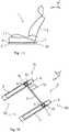
- Fig. 1A shows a side view of a feasible embodiment of a vehicle seat 1, the vehicle seat comprising at least one longitudinal adjuster 2 having a guide rail arrangement SA.
- Fig. 1B shows a perspective view of a feasible embodiment of a longitudinal adjuster 2 having a guide rail arrangement SA.
- the arrangement of the vehicle seat 1 in a vehicle is defined by means of the coordinate system used below; the coordinate system comprises a vertical axis z designated for a vertical direction of the vehicle, a longitudinal axis x designated for a longitudinal direction of the vehicle and a transverse axis y designated for a transverse direction of the vehicle.
- the vehicle seat 1 for example comprises a seat face 1.1 and a backrest 1.2 arranged at the seat face 1.1.
- the longitudinal adjuster 2 is arranged to be used for longitudinal movability of the vehicle seat 1, and as shown in fig. 1B comprises two guide rail pairs PI, P2 of seat guide rails 3, 4.
- the corresponding guide rail pair P1 or P2 has a lower first seat guide rail 3, and an upper second seat guide rail 4 that is movable in the longitudinal direction relative to the lower seat guide rail 3.
- the upper seat guide rail 4 is arranged and fastened at the seat face 1.1.
- the lower seat guide rail 3 is arranged so as to be fixed relative to the vehicle and is fastened at a vehicle structure, e.g. at a vehicle base plate.
- the lower first seat guide rail 3 and the upper second seat guide rail 4 in particular form an independent guide rail pair PI, P2, wherein one guide rail pair P1 or P2 is arranged on each side of the vehicle seat 1 for example.
- the longitudinal adjuster 2 comprises a gear unit G, which is connected, in particular loosenably connected, at least to the first seat guide rail 4 of at least one of the guide rail pairs P1.
- the two guide rail pairs PI, P2 both have one gear unit G.
- the two guide rail pairs P1, P2 are connected to each other by means of a transmission unit 11.
- an electric motor unit 12 is provided; the electric motor unit is coupled to the transmission unit 11.
- the gear unit G comprises at least one gear rotary shaft 6, the gear rotary shaft having a rotatable gear element 7, such as a threaded worm gear, which acts jointly with the gear rotary shaft.
- the transmission unit 11 is coupled to the gear unit G and the electric motor unit 12 in order to transmit a torsional force of the electric motor unit 12 to the gear rotary shaft 6.
- the gear unit G is accommodated at least partially by means of at least one gearbox 9.
- the longitudinal adjuster 2 comprises a support 5 in order to receive the gearbox 9; as shown in figs. 1B and 2A - 2B , the support extends partially from the upper seat guide rail 4.
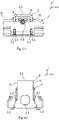
- Figs. 2A and 2B show a perspective view or a sectional view of the longitudinal adjuster 2; the longitudinal adjuster comprises the lower seat guide rail 3, the upper seat guide rail 4 and the gear unit G.
- the support 5, together with the gearbox 9 that is received and secured in the support 5, is arranged in a cavity BR (also called a structural space) formed between the lower first seat guide rail 3 and the upper second seat guide rail 4.
- the support 5 passes through a guide rail opening 13 in the upper guide rail 4 and extends at least partially from the guide rail opening.
- the support 5 closes the guide rail opening 13 and thereby covers the gearbox 9 and a guide rail interior space located below.
- the lower seat guide rail 3 and the upper seat guide rail 4 are wrapped around one another by means of a substantially U-shaped shape characteristic thereof; these profiles have guide rail side walls 3.1, 4.1 which are folded inward or outward. A closed guide rail shape characteristic is thereby formed.
- the longitudinal adjuster 2 in the structural space or cavity BR defined by the guide rail shape characteristic comprises the gear rotary shaft 6, which is connected in a fixed manner to the lower seat guide rail 3 and runs in the longitudinal direction (x-axis).
- one fixing element 3.2, 3.3 is respectively arranged in the lower seat guide rail 3 in order to secure the gear rotary shaft 6 in the lower seat guide rail 3.
- the fixing elements 3.2, 3.3 are in particular correspondingly arranged in extremity regions, formed in the longitudinal direction, of the lower seat guide rail 3.
- at least one fixing element 3.3 may be formed as a block element, which holds the gear rotary shaft 6 in place; and one other fixing element 3.2 may be formed as an L-shaped connecting plate, which has a through-opening 3.2.1 for causing the gear rotary shaft 6 to run through and securing same.
- the gear rotary shaft 6 extends substantially over the length of the lower seat guide rail 3, wherein a rotary shaft length SL of the gear rotary shaft 6 is less than the total distance GA between the two fixing elements 3.2 and 3.3.
- the gear rotary shaft 6 for example at least has a length in the range of 280 mm - 330 mm, in particular 320 mm, wherein a movement travel F of the gear unit G and thus the vehicle seat 1 has a maximum length in the range of 240 mm - 280 mm, e.g. at least 260 mm.
- the longitudinal adjuster 2 comprises one rotatable gear element 7, which acts jointly with the gear rotary shaft 6 used for longitudinal adjustment.
- the gear element 7 comprises a rotary shaft nut 7.1, which is rotatably arranged on the threaded rotary shaft 6.
- the rotary shaft nut 7.1 has an external tooth part; a drive element 8 arranged perpendicularly to the threaded rotary shaft 6 is engaged in the external tooth part.
- the longitudinal adjuster 2 for example comprises a worm gear 8.1 (also called a drive worm gear) as the drive element 8 connected to the gear element 7; the worm gear and the gear element 7 are gear-meshed.
- the drive element 8 is in effective connection with the electric motor unit 12 (also called a drive electric motor) of the longitudinal adjuster 2 for example by means of the transmission unit 11.
- the gearbox 9 used for receiving the gear element 7 and the drive element 8 is disposed in the upper second seat guide rail 4.
- the gearbox 9 is in particular formed so as to support and secure the gear element 7 and the drive element 8, with the maximum rigidity and strength possible, in the structural space BR defined by the guide rail shape characteristic.
- the gearbox 9 comprises multiple box body parts 9.1 - 9.6, wherein two of the box body side parts 9.1, 9.5 and one box body upper part 9.3 and one box body lower part 9.6 can be seen respectively in figs. 2A and 2B which are shown.
- the box body parts 9.1 - 9.6 are for example connected to each other in a material-fitting, shape-fitting and/or force-fitting manner.
- the box body parts 9.1 - 9.6 are for example inserted in each other, and in particular connected to each other in a locked manner. Alternatively or additionally, these box body parts may be screwed, riveted or welded to each other.
- the gearbox 9 comprises the box body upper part 9.3; the box body upper part is connected in a material-fitting, shape-fitting and/or force-fitting manner at least to one of the lateral box body side parts 9.1, 9.2, 9.4 and 9.5.
- a gearbox section runs through the guide rail opening 13 formed in an upper side O of the upper second seat guide rail 4.
- the longitudinal adjuster 2 comprises the support 5.
- the support 5 is arranged in the upper second seat guide rail 4 and connected to the seat guide rail.
- the support 5 is formed to be U-shaped, and in particular is formed as a U-shaped securing clamp.
- the support 5 comprises two fixing legs 5.2; the fixing legs are connected at a leg extremity by means of a section 5.3 connecting extremities of the fixing legs 5.2.
- the support 5 has a leg opening 5.1. In inserted and assembled states of the gear unit G, the leg opening 5.1 is oriented in the direction of the lower first seat guide rail 3.
- the support 5 has fixing legs 5.2 which are spaced apart from one another, connected to the second seat guide rail 4 and formed vertically.
- the fixing legs 5.2 are connected to each other by means of the section 5.3, which is formed substantially horizontally.
- the fixing legs 5.2 are for example connected in a material-fitting, force-fitting and/or shape-fitting manner to the respectively corresponding box body side parts 9.1 and 9.5.
- the fixing legs 5.2 are in particular welded to the corresponding box body parts 9.1 and 9.5 respectively.
- each fixing leg 5.2 of the support 5 formed in the U-shape is connected to the second seat guide rail 4.
- each fixing leg 5.2 comprises at least one coupling element; the fixing leg 5.2 is secured at the second seat guide rail 4 by means of the coupling element.
- the corresponding fixing leg 5.2 is connected to the second seat guide rail 4 at three sides S1 - S3.
- the support 5 is in particular connected in a shape-fitting (e.g. locking), force-fitting (e.g. elastically clamping) or material-fitting (e.g. welding) manner to the second seat guide rail 4 at mutually corresponding positions.
- each of the fixing legs 5.2 has a through-opening 5.4 for causing the gear rotary shaft 5 to run through.
- the box body upper part 9.3 is spaced apart from an inner wall of the section 5.3 of the support 5.
- a distance A is in the range of a few millimeters, in particular in the range of 1 mm - 3 mm, e.g. 1.5 mm.
- the L-shaped fixing element 3.2 can be arranged in the longitudinal adjuster 2 in a manner whereby the structural space is utilized.
- a lower fastening side 3.2.2 of the L-shaped fixing element 3.2 is below the gear rotary shaft 6 and oriented parallel to the gear rotary shaft and in particular in the direction of the gear rotary shaft 6 and extending into the structural space BR.
- the fixing element 3.2 is formed in such a way that the fixing element forms an extremity stop member for the support 5 in the course of longitudinal adjustment.
- Fig. 3 shows a perspective view of the gear rotary shaft 6, the support 5 arranged at the gear rotary shaft 6, and the L-shaped fixing element 3.2 having the inwardly oriented fastening side 3.2.2.
- the inwardly oriented fastening side 3.2.2 is in particular understood to be the orientation of the fastening side 3.2.2 inward into the structural space BR of the relevant guide rail pair P1 or P2.
- each fixing leg 5.2 has a protruding part 5.5 at each lateral edge region R.
- the shapes of the corresponding protruding parts 5.5 correspond to lateral recesses 4.2 of the second guide rail 4.
- the lateral recesses 4.2, 4.3 are respectively shown in figs. 6A and 6B .
- the protruding parts 5.5 are in particular correspondingly arranged in a lower region of the fixing legs 5.2.
- the protruding parts 5.5 are correspondingly formed to be stepped, and extend perpendicularly from the corresponding lateral edge region R.
- Figs. 4A and 4B show a cross section of the gear unit G or a top view of the support 5 according to fig. 3 .
- the support 5 for example has a predetermined width B (in the transverse direction), a predetermined height H (in the vertical direction) and a predetermined length L (distance, extension size of the support 5 in the longitudinal direction).
- the total weight of the gear unit G formed by the support 5, the gearbox 9 having the gear element 7 and the drive element 8 is especially light and is in the range of 55 g - 100 g, in particular 60 g - 70 g, and for example is 67 g.
- Figs. 5A and 5B show a top view and a cross section of the gearbox 9 of the longitudinal adjuster 2 according to figs. 2A and 2B .
- the gearbox 9 is formed to have multiple members and comprises multiple box body parts 9.1 - 9.6.
- Fig. 5A shows a top view of the gearbox 9, which comprises the box body side parts 9.1, 9.2, 9.4 and 9.5 and one box body upper part 9.3 as box body parts.
- Fig. 5B shows a cross section of the gearbox 9 having the two box body side parts 9.1 and 9.5 and the box body upper part 9.3 and one box body lower part 9.6.
- the box body parts 9.1 - 9.6 are connected to each other in a shape-fitting, force-fitting and/or material-fitting manner.
- the box body parts are in close contact with each other in particular locally, for example via edges or borders thereof.
- the box body parts 9.1 - 9.6 are for example clamped, locked, plugged, screwed, welded or bonded to each other.
- the gearbox 9 in particular has dimensions adapted to the support 5 and/or an adapted shape, or vice versa.
- the gearbox 9 for example has a predetermined width B (in the transverse direction), a predetermined height H (in the vertical direction) and a predetermined length L.
- the weight of the gearbox 9 having the drive element 8 and the gear element 7 arranged inside the gearbox 9 is for example in the range of 25 g - 50 g.
- Figs. 6A and 6B show a side view or a top view of an embodiment of the second seat guide rail 4 having the support 5 of the longitudinal adjuster 2.
- the recesses 4.2 for receiving the protruding parts 5.5 of the support 5 in a shape-fitting manner are shown in the embodiment shown.
- another recess 4.3 is shown; this recess is for example formed to be used for causing the drive element 8 to run through in the transverse direction.
Landscapes
- Engineering & Computer Science (AREA)
- Aviation & Aerospace Engineering (AREA)
- Transportation (AREA)
- Mechanical Engineering (AREA)
- Seats For Vehicles (AREA)
Abstract
Description
- The present invention relates to a longitudinal adjuster for a vehicle seat, in particular for a motor vehicle seat, and a vehicle seat.
- Longitudinal adjusters are already known from the prior art, wherein a gear mechanism is arranged in a gearbox and coupled to a seat guide rail of the longitudinal adjuster.
- An object of the present invention is to propose a longitudinal adjuster for a vehicle seat that is improved relative to the prior art, and an improved vehicle seat.
- In terms of the longitudinal adjuster, the object according to the present invention is achieved through the features of
claim 1. In terms of the vehicle seat, the object according to the present invention is achieved through the features ofclaim 13. - A longitudinal adjuster for a vehicle seat, in particular for a motor vehicle seat, for a motorized longitudinal adjustment of the vehicle seat, comprises a guide rail arrangement, having two guide rail pairs of seat guide rails, wherein the corresponding guide rail pair comprises a first seat guide rail and a second seat guide rail that is movable relative to the first seat guide rail. In addition, the longitudinal adjuster comprises: an electric motor unit; a gear unit having at least one gear rotary shaft connected firmly at least to the first seat guide rail of one of the pairs; and a rotatable gear element, such as a worm gear, which acts jointly with the gear rotary shaft. The longitudinal adjuster further comprises: a transmission unit, coupled to the gear unit and the electric motor unit in order to transmit a torsional force of the electric motor unit to the gear rotary shaft; and a gearbox which at least partially accommodates the gear unit; and a support for receiving the gearbox. Here, the support, together with the gearbox, is arranged in a cavity formed between the first seat guide rail and the second seat guide rail of one guide rail pair, and passes through a guide rail opening in the second guide rail and extends from the guide rail opening at least partially in such a way that the support closes the guide rail opening in the second guide rail.
- In an exemplary embodiment, the support is formed in such a way that the gearbox is arranged between two fixing legs of the support, the fixing legs being spaced apart from one another in a longitudinal direction and extending vertically. Here, the two fixing legs are in particular coupled to the second seat guide rail, and in particular are connected to the second seat guide rail at least in a shape-fitting or force-fitting manner.
- In another embodiment, the support is formed in a U-shape, wherein a leg opening of the support formed in the U-shape points in the direction of the first seat guide rail, and a middle space formed by the fixing legs comprises the gearbox. Thus, the gearbox is covered in relation to an upper side of the second seat guide rail (i.e. the upper guide rail) by means of a section of the support connecting the two fixing legs. The U-shaped support for example has the shape of a clamp element and/or a saddle seat. In addition, each of the fixing legs has a through-opening for causing the gear rotary shaft to run through.
- An advantage achieved by the present invention is in particular that the longitudinal adjuster can be formed to be compact as possible by means of the support according to the present invention. Thus, a guide rail arrangement that is substantially flatter and more compact than a conventional guide rail arrangement can in particular be formed. For this purpose, additional reinforcing elements and covering elements for fixing and protecting the gearbox are for example omitted. Due to an installation height (in a vertical direction) required by the gear element (worm gear) screwed onto the gear rotary shaft, the gearbox for example extends from the upper side of the second seat guide rail.
- In an exemplary embodiment of the longitudinal adjuster, the support formed in the U-shape is at least connected to the second seat guide rail in a shape-fitting, force-fitting and/or material-fitting manner. Exterior contours of the fixing legs and the section connecting the fixing legs are in particular correspondingly matched to a guide rail shape characteristic (in particular a guide rail interior shape characteristic) of the second seat guide rail. Thus, other fastening elements (e.g. screws or rivets) are not needed to fasten the support of the second guide rail (in particular the upper guide rail). By means of this type of exterior contour of the support corresponding to the guide rail interior contour/guide rail interior shape characteristic, the support can be secured in the second guide rail in a shape-fitting or force-fitting manner, e.g. by clamping or gripping, at an inner side. It is thereby possible to reduce installation time and lower material costs.
- In a feasible embodiment, the support is secured in the guide rail opening of the second guide rail in a force-fitting or shape-fitting manner, in particular secured by clamping or gripping. For this purpose, the fixing legs are for example formed to be flexible. The fixing legs are for example formed in the form of elastic clamping arms, wherein when the support is inserted by means of the fixing legs pointing toward the guide rail opening, the fixing legs are pressed inward against a spring force. In an inserted state, the fixing legs automatically and elastically bite outward and clamp the support in the guide rail opening. In other words: the support is for example secured in a clamping seat in the guide rail opening.
- Additionally or alternatively, the support may be secured in a force-fitting or shape-fitting manner, in particular secured by clamping or gripping, in a recess in a side wall of the second guide rail.
- Thereby, the longitudinal adjuster may be formed in such a way that the second seat guide rail comprises multiple recesses. The upper side of the seat guide rail has at least one recess as the guide rail opening; the guide rail opening is used for receiving the connecting section of the support formed in the U-shape. The mechanical strength and load capacity of the second seat guide rail are for example lowered in the longitudinal direction and a transverse direction, by means of the guide rail opening formed in the upper side.
- The guide rail opening is closed simply and the gearbox is covered toward the outside by means of the arrangement, inverted in particular in relation to the vertical axis, of the U-shaped support (also called a securing clamp) having a closed section extending upward from the second seat guide rail in an inserted state of the support.
- Here, the U-shaped support with the inverted arrangement can at least be arranged in a shape-fitting or force-fitting manner in the guide rail opening of the second seat guide rail and used as a reinforcing element of the second seat guide rail. In addition, a box body region, extending from the upper side of the second seat guide rail, of the gearbox is covered by the support and protected from external influences. Thus, the U-shaped support is arranged to be used for fastening and locating and covering the gearbox and used for reinforcing the second seat guide rail.
- In addition, a space below the U-shaped support, in particular a space between the first seat guide rail (the lower guide rail) and the support, is expanded. For this purpose, the fixing legs for example extend outward and are arranged at a predetermined leg angle relative to each other. Due to the inverted arrangement of the U-shaped support, this expanded space is in particular located below the connecting section and points inward toward the guide rail interior space and forms the guide rail interior space. Thus, other components of the longitudinal adjuster may be arranged in these internal installation spaces which are thereby formed again.
- The support for example has a width of 17.8 mm (in the transverse direction), a height of 32 mm (in the vertical direction) and a length of 29.4 mm (in the longitudinal direction). The distance between an upper side of the gearbox and a lower side of the support may for example be 1.7 mm. The total weight of a structural unit formed by the support and the gearbox having the gear element is for example 66.9 g.
- In an improved solution, a box body side part of the gearbox may be formed to be narrow to a very large degree, such that the gearbox has a width (in the transverse direction) in the range of 15 mm - 20 mm, e.g. 17 mm; a height (in the vertical direction) in the range of 20 mm - 30 mm, e.g. 27 mm; and a length (in the longitudinal direction) in the range of 20 mm - 26 mm, e.g. 24 mm. The weight of the gearbox having the gear element arranged inside the gearbox is for example in the range of 30 g - 38 g, e.g. 34 g.
- In addition, the support formed in the U-shape can be produced in a simple manner. For example, the U-shaped support can be produced by means of an injection moulding method or a pressing method and/or a folding method.
- A feasible embodiment of the longitudinal adjuster proposes that the fixing legs respectively comprise at least multiple protruding parts arranged at a lateral edge region, wherein shapes of corresponding protruding parts correspond to shapes of lateral recesses of the second seat guide rail. The protruding parts are in particular correspondingly arranged in a lower lateral edge region of the fixing legs. In addition, the protruding parts are correspondingly formed to be stepped. The support is at least secured in a force-fitting or shape-fitting manner, in particular fastened, in the second seat guide rail.
- In another embodiment, the protruding parts are at least formed in a flexible manner, e.g. formed of plastic, wherein the protruding parts are secured, in particular secured in a clamping, locking or biting manner, in the corresponding recesses in order to perform shape-fitting or force-fitting connection. In another embodiment, the protruding parts are for example formed to be graded. This can achieve pre-locking of components of the longitudinal adjuster when the longitudinal adjuster is being assembled, for example for the orientation of these components, and thereby achieve fixing of these components with respect to each other.
- In another embodiment, the gearbox is at least connected to the fixing legs of the support formed in the U-shape. Thus, the gearbox is supported by the fixing legs in particular when the second seat guide rail is executing longitudinal shifting.
- Additionally, viewed in the longitudinal direction, the guide rail opening has a stop element for the outwardly extending fixing leg at opposite opening sides respectively. Alternatively or additionally, each fixing leg may have an outward-pointing locking nose at a leg outer side thereof; the locking nose is for example engaged in the associated stop element in a locking manner.
- In an improved solution, a vehicle seat is equipped with the longitudinal adjuster, for the purpose of longitudinally adjusting the vehicle seat in a motorized fashion.
- Embodiments of the present invention are explained in detail by means of the accompanying drawings.
- The following are shown in the drawings:
-
Fig. 1A shows schematically a side view of a vehicle seat having a longitudinal adjuster; -
Fig. 1B shows schematically a perspective view of a guide rail arrangement for a longitudinal adjuster; -
Figs. 2A and2B show schematically a perspective view or a sectional view respectively of an embodiment of the longitudinal adjuster; -
Fig. 3 shows schematically a perspective view of bearing elements arranged at the gear rotary shaft of the longitudinal adjuster according tofigs. 2A and2B ; -
Figs. 4A and 4B show schematically a cross section or a top view of the support according tofig. 3 . -
Figs. 5A and 5B show schematically a top view and a cross section of the gearbox of the longitudinal adjuster according tofigs. 2A and2B ; and -
Figs. 6A and 6B show schematically a side view or a top view of an embodiment of the second seat guide rail having the support of the longitudinal adjuster. - Compounds which correspond to each other are provided with identical reference symbols in all of the drawings.
-
Fig. 1A shows a side view of a feasible embodiment of avehicle seat 1, the vehicle seat comprising at least onelongitudinal adjuster 2 having a guide rail arrangement SA. -
Fig. 1B shows a perspective view of a feasible embodiment of alongitudinal adjuster 2 having a guide rail arrangement SA. - Here, the arrangement of the
vehicle seat 1 in a vehicle is defined by means of the coordinate system used below; the coordinate system comprises a vertical axis z designated for a vertical direction of the vehicle, a longitudinal axis x designated for a longitudinal direction of the vehicle and a transverse axis y designated for a transverse direction of the vehicle. - The
vehicle seat 1 for example comprises a seat face 1.1 and a backrest 1.2 arranged at the seat face 1.1. - The
longitudinal adjuster 2 is arranged to be used for longitudinal movability of thevehicle seat 1, and as shown infig. 1B comprises two guide rail pairs PI, P2 ofseat guide rails - Thereby, the corresponding guide rail pair P1 or P2 has a lower first
seat guide rail 3, and an upper secondseat guide rail 4 that is movable in the longitudinal direction relative to the lowerseat guide rail 3. In the embodiment shown, the upperseat guide rail 4 is arranged and fastened at the seat face 1.1. - The lower
seat guide rail 3 is arranged so as to be fixed relative to the vehicle and is fastened at a vehicle structure, e.g. at a vehicle base plate. - The lower first
seat guide rail 3 and the upper secondseat guide rail 4 in particular form an independent guide rail pair PI, P2, wherein one guide rail pair P1 or P2 is arranged on each side of thevehicle seat 1 for example. - The
longitudinal adjuster 2 comprises a gear unit G, which is connected, in particular loosenably connected, at least to the firstseat guide rail 4 of at least one of the guide rail pairs P1. In the embodiment shown, the two guide rail pairs PI, P2 both have one gear unit G. - The two guide rail pairs P1, P2 are connected to each other by means of a
transmission unit 11. In order to longitudinally adjust theseat 1 in a motorized fashion, anelectric motor unit 12 is provided; the electric motor unit is coupled to thetransmission unit 11. - As shown below in
figs. 2A and2B , the gear unit G comprises at least one gear rotary shaft 6, the gear rotary shaft having arotatable gear element 7, such as a threaded worm gear, which acts jointly with the gear rotary shaft. - The
transmission unit 11 is coupled to the gear unit G and theelectric motor unit 12 in order to transmit a torsional force of theelectric motor unit 12 to the gear rotary shaft 6. - In addition, as shown in
figs. 2A and2B , the gear unit G is accommodated at least partially by means of at least onegearbox 9. - The
longitudinal adjuster 2 comprises asupport 5 in order to receive thegearbox 9; as shown infigs. 1B and2A - 2B , the support extends partially from the upperseat guide rail 4. -
Figs. 2A and2B show a perspective view or a sectional view of thelongitudinal adjuster 2; the longitudinal adjuster comprises the lowerseat guide rail 3, the upperseat guide rail 4 and the gear unit G. - Here, the
support 5, together with thegearbox 9 that is received and secured in thesupport 5, is arranged in a cavity BR (also called a structural space) formed between the lower firstseat guide rail 3 and the upper secondseat guide rail 4. In addition, thesupport 5 passes through aguide rail opening 13 in theupper guide rail 4 and extends at least partially from the guide rail opening. Here, thesupport 5 closes theguide rail opening 13 and thereby covers thegearbox 9 and a guide rail interior space located below. - The lower
seat guide rail 3 and the upperseat guide rail 4 are wrapped around one another by means of a substantially U-shaped shape characteristic thereof; these profiles have guide rail side walls 3.1, 4.1 which are folded inward or outward. A closed guide rail shape characteristic is thereby formed. - In addition, the
longitudinal adjuster 2 in the structural space or cavity BR defined by the guide rail shape characteristic comprises the gear rotary shaft 6, which is connected in a fixed manner to the lowerseat guide rail 3 and runs in the longitudinal direction (x-axis). - For example, one fixing element 3.2, 3.3 is respectively arranged in the lower
seat guide rail 3 in order to secure the gear rotary shaft 6 in the lowerseat guide rail 3. The fixing elements 3.2, 3.3 are in particular correspondingly arranged in extremity regions, formed in the longitudinal direction, of the lowerseat guide rail 3. Here, at least one fixing element 3.3 may be formed as a block element, which holds the gear rotary shaft 6 in place; and one other fixing element 3.2 may be formed as an L-shaped connecting plate, which has a through-opening 3.2.1 for causing the gear rotary shaft 6 to run through and securing same. - The gear rotary shaft 6 extends substantially over the length of the lower
seat guide rail 3, wherein a rotary shaft length SL of the gear rotary shaft 6 is less than the total distance GA between the two fixing elements 3.2 and 3.3. - The gear rotary shaft 6 for example at least has a length in the range of 280 mm - 330 mm, in particular 320 mm, wherein a movement travel F of the gear unit G and thus the
vehicle seat 1 has a maximum length in the range of 240 mm - 280 mm, e.g. at least 260 mm. - In addition, the
longitudinal adjuster 2 comprises onerotatable gear element 7, which acts jointly with the gear rotary shaft 6 used for longitudinal adjustment. - The
gear element 7 comprises a rotary shaft nut 7.1, which is rotatably arranged on the threaded rotary shaft 6. The rotary shaft nut 7.1 has an external tooth part; a drive element 8 arranged perpendicularly to the threaded rotary shaft 6 is engaged in the external tooth part. - In the embodiment shown, the
longitudinal adjuster 2 for example comprises a worm gear 8.1 (also called a drive worm gear) as the drive element 8 connected to thegear element 7; the worm gear and thegear element 7 are gear-meshed. In addition, the drive element 8 is in effective connection with the electric motor unit 12 (also called a drive electric motor) of thelongitudinal adjuster 2 for example by means of thetransmission unit 11. - The
gearbox 9 used for receiving thegear element 7 and the drive element 8 is disposed in the upper secondseat guide rail 4. Thegearbox 9 is in particular formed so as to support and secure thegear element 7 and the drive element 8, with the maximum rigidity and strength possible, in the structural space BR defined by the guide rail shape characteristic. - The
gearbox 9 comprises multiple box body parts 9.1 - 9.6, wherein two of the box body side parts 9.1, 9.5 and one box body upper part 9.3 and one box body lower part 9.6 can be seen respectively infigs. 2A and2B which are shown. The box body parts 9.1 - 9.6 are for example connected to each other in a material-fitting, shape-fitting and/or force-fitting manner. The box body parts 9.1 - 9.6 are for example inserted in each other, and in particular connected to each other in a locked manner. Alternatively or additionally, these box body parts may be screwed, riveted or welded to each other. - In order to cover the drive element 8 arranged on the
gear element 7, thegearbox 9 comprises the box body upper part 9.3; the box body upper part is connected in a material-fitting, shape-fitting and/or force-fitting manner at least to one of the lateral box body side parts 9.1, 9.2, 9.4 and 9.5. - In the embodiment shown, a gearbox section runs through the
guide rail opening 13 formed in an upper side O of the upper secondseat guide rail 4. - In order to secure and reinforce the
gearbox 9, thelongitudinal adjuster 2 comprises thesupport 5. - The
support 5 is arranged in the upper secondseat guide rail 4 and connected to the seat guide rail. Here, thesupport 5 is formed to be U-shaped, and in particular is formed as a U-shaped securing clamp. Here, thesupport 5 comprises two fixing legs 5.2; the fixing legs are connected at a leg extremity by means of a section 5.3 connecting extremities of the fixing legs 5.2. At opposite extremities of the fixing legs 5.2, thesupport 5 has a leg opening 5.1. In inserted and assembled states of the gear unit G, the leg opening 5.1 is oriented in the direction of the lower firstseat guide rail 3. - In addition, in the longitudinal direction (x-axis), the
support 5 has fixing legs 5.2 which are spaced apart from one another, connected to the secondseat guide rail 4 and formed vertically. The fixing legs 5.2 are connected to each other by means of the section 5.3, which is formed substantially horizontally. The fixing legs 5.2 are for example connected in a material-fitting, force-fitting and/or shape-fitting manner to the respectively corresponding box body side parts 9.1 and 9.5. The fixing legs 5.2 are in particular welded to the corresponding box body parts 9.1 and 9.5 respectively. - In addition, each fixing leg 5.2 of the
support 5 formed in the U-shape is connected to the secondseat guide rail 4. For this purpose, each fixing leg 5.2 comprises at least one coupling element; the fixing leg 5.2 is secured at the secondseat guide rail 4 by means of the coupling element. - For example, the corresponding fixing leg 5.2 is connected to the second
seat guide rail 4 at three sides S1 - S3. Thesupport 5 is in particular connected in a shape-fitting (e.g. locking), force-fitting (e.g. elastically clamping) or material-fitting (e.g. welding) manner to the secondseat guide rail 4 at mutually corresponding positions. - In addition, each of the fixing legs 5.2 has a through-opening 5.4 for causing the gear
rotary shaft 5 to run through. In addition, the box body upper part 9.3 is spaced apart from an inner wall of the section 5.3 of thesupport 5. A distance A is in the range of a few millimeters, in particular in the range of 1 mm - 3 mm, e.g. 1.5 mm. - Due to the arrangement shown of the
support 5 formed in the U-shape, the L-shaped fixing element 3.2 can be arranged in thelongitudinal adjuster 2 in a manner whereby the structural space is utilized. A lower fastening side 3.2.2 of the L-shaped fixing element 3.2 is below the gear rotary shaft 6 and oriented parallel to the gear rotary shaft and in particular in the direction of the gear rotary shaft 6 and extending into the structural space BR. The fixing element 3.2 is formed in such a way that the fixing element forms an extremity stop member for thesupport 5 in the course of longitudinal adjustment. -
Fig. 3 shows a perspective view of the gear rotary shaft 6, thesupport 5 arranged at the gear rotary shaft 6, and the L-shaped fixing element 3.2 having the inwardly oriented fastening side 3.2.2. The inwardly oriented fastening side 3.2.2 is in particular understood to be the orientation of the fastening side 3.2.2 inward into the structural space BR of the relevant guide rail pair P1 or P2. - In the embodiment shown, each fixing leg 5.2 has a protruding part 5.5 at each lateral edge region R. The shapes of the corresponding protruding parts 5.5 correspond to lateral recesses 4.2 of the
second guide rail 4. The lateral recesses 4.2, 4.3 are respectively shown infigs. 6A and 6B . - The protruding parts 5.5 are in particular correspondingly arranged in a lower region of the fixing legs 5.2. In addition, the protruding parts 5.5 are correspondingly formed to be stepped, and extend perpendicularly from the corresponding lateral edge region R.
- In addition, when the upper
seat guide rail 4 is being longitudinally adjusted, there is sufficient structural space BR below the threaded rotary shaft 6 and below thesupport 5 to receive afastening pin 10 of the fixing element 3.2. -
Figs. 4A and 4B show a cross section of the gear unit G or a top view of thesupport 5 according tofig. 3 . - The
support 5 for example has a predetermined width B (in the transverse direction), a predetermined height H (in the vertical direction) and a predetermined length L (distance, extension size of thesupport 5 in the longitudinal direction). The total weight of the gear unit G formed by thesupport 5, thegearbox 9 having thegear element 7 and the drive element 8 is especially light and is in the range of 55 g - 100 g, in particular 60 g - 70 g, and for example is 67 g. -
Figs. 5A and 5B show a top view and a cross section of thegearbox 9 of thelongitudinal adjuster 2 according tofigs. 2A and2B . - The
gearbox 9 is formed to have multiple members and comprises multiple box body parts 9.1 - 9.6. -
Fig. 5A shows a top view of thegearbox 9, which comprises the box body side parts 9.1, 9.2, 9.4 and 9.5 and one box body upper part 9.3 as box body parts. -
Fig. 5B shows a cross section of thegearbox 9 having the two box body side parts 9.1 and 9.5 and the box body upper part 9.3 and one box body lower part 9.6. The box body parts 9.1 - 9.6 are connected to each other in a shape-fitting, force-fitting and/or material-fitting manner. For this purpose, the box body parts are in close contact with each other in particular locally, for example via edges or borders thereof. Here, the box body parts 9.1 - 9.6 are for example clamped, locked, plugged, screwed, welded or bonded to each other. - The
gearbox 9 in particular has dimensions adapted to thesupport 5 and/or an adapted shape, or vice versa. - The
gearbox 9 for example has a predetermined width B (in the transverse direction), a predetermined height H (in the vertical direction) and a predetermined length L. The weight of thegearbox 9 having the drive element 8 and thegear element 7 arranged inside thegearbox 9 is for example in the range of 25 g - 50 g. -
Figs. 6A and 6B show a side view or a top view of an embodiment of the secondseat guide rail 4 having thesupport 5 of thelongitudinal adjuster 2. - The recesses 4.2 for receiving the protruding parts 5.5 of the
support 5 in a shape-fitting manner are shown in the embodiment shown. In addition, another recess 4.3 is shown; this recess is for example formed to be used for causing the drive element 8 to run through in the transverse direction. -
- 1
- vehicle seat
- 1.1
- seat face
- 1.2
- backrest
- 2
- longitudinal adjuster
- 3, 4
- seat guide rail
- 3.1, 4.1
- guide rail side walls
- 3.2, 3.3
- fixing element
- 3.2.1
- through-opening
- 3.2.2
- fastening side
- 4.2 - 4.3
- recesses
- 5
- support
- 5.1
- leg opening
- 5.2
- fixing leg
- 5.3
- section
- 5.4
- through-opening
- 5.5
- protruding part
- 6
- gear rotary shaft
- 7
- gear element
- 7.1
- rotary shaft nut
- 8
- drive element
- 8.1
- worm gear
- 9
- gearbox
- 9.1 - 9.6
- box body parts
- 9.1, 9.2, 9.4, 9.5
- box body side parts
- 9.3
- box body upper part
- 9.6
- box body lower part
- 10
- fastening pin
- 11
- transmission unit
- 12
- electric motor unit
- 13
- guide rail opening
- x, y, z
- axes
- A
- distance
- B
- width
- BR
- cavity/structural space
- F
- movement travel
- G
- gear unit
- GA
- total distance
- H
- height
- L
- length
- O
- upper side
- P1, P2
- guide rail pair
- R1
- edge region
- S1 - S3
- sides
- SA
- guide rail arrangement
- SL
- rotary shaft lengthn
Claims (13)
- A longitudinal adjuster (2) for a vehicle seat (1), comprising- a guide rail arrangement (SA), having two guide rail pairs (PI, P2) of seat guide rails (3, 4), wherein the corresponding guide rail pair comprises- a first seat guide rail (3),- a second seat guide rail (4) that is movable relative to the first seat guide rail (3),- an electric motor unit (12),- a gear unit (G), having at least one gear rotary shaft (6) formed to be connected at least to the first seat guide rail (3) of one of the guide rail pairs (PI, P2),- a rotatable gear element (7), which acts jointly with the gear rotary shaft (6),- a transmission unit (11), coupled to the gear unit (G) and the electric motor unit (12) in order to transmit a torsional force of the electric motor unit (12) to the gear rotary shaft (6),- a gearbox (9), which at least partially accommodates the gear unit (G), and- a support (5), for receiving the gearbox (9), wherein the support (5), together with the gearbox (9), is arranged in a cavity (BR) formed between the first seat guide rail (3) and the second seat guide rail (4) of one guide rail pair (PI), and passes through a guide rail opening (13) in the second guide rail (4) and extends from the guide rail opening at least partially in such a way that the support (5) closes the guide rail opening (13) in the second guide rail.
- The longitudinal adjuster (2) as claimed in claim 1, wherein the support (5) is at least connected to the second seat guide rail (4), in particular to the guide rail opening (13), in a shape-fitting, force-fitting or material-fitting manner.
- The longitudinal adjuster (2) as claimed in claim 1 or 2, wherein the support (5) is formed as a U-shaped clamp, which has two fixing legs (5.2) and a section (5.3) connecting the two fixing legs.
- The longitudinal adjuster (2) as claimed in claim 3, wherein a leg opening (5.1) of the support (5) formed in the U-shape is oriented in the direction of the first seat guide rail (3), such that the gearbox (9) is covered in relation to an upper side of the second seat guide rail (4) by means of the section (5.3) of the support (5) connecting the two fixing legs (5.2).
- The longitudinal adjuster (2) as claimed in claim 3 or 4, wherein each fixing leg (5.2) comprises at least one coupling element; the fixing leg (5.2) is secured at the second seat guide rail (4) by means of the coupling element.
- The longitudinal adjuster (2) as claimed in one of the preceding claims, wherein each fixing leg (5.2) is connected to the second seat guide rail (4) at three sides (S1 - S3).
- The longitudinal adjuster (2) as claimed in one of the preceding claims, wherein viewed in a longitudinal direction, the guide rail opening (13) has a stop element at opposite opening sides respectively.
- The longitudinal adjuster (2) as claimed in one of the preceding claims, wherein the second seat guide rail (4) comprises multiple recesses (4.2 - 4.3).
- The longitudinal adjuster (2) as claimed in one of claims 2 - 8 above, wherein the fixing legs (5.2) respectively comprise at least multiple protruding parts arranged at a lateral edge region (R), wherein shapes of corresponding protruding parts correspond to shapes of lateral recesses (4.2 - 4.3) of the second seat guide rail (4).
- The longitudinal adjuster (2) as claimed in claim 9, wherein the protruding parts are correspondingly arranged in the lateral edge region (R) at the bottom of the fixing legs (5.2).
- The longitudinal adjuster (2) as claimed in claim 9 or 10, wherein the protruding parts are correspondingly formed to be stepped.
- The longitudinal adjuster as claimed in one of claims 2 - 11, wherein the gearbox (9) is at least connected to the fixing legs (5.2) in a shape-fitting or force-fitting manner.
- A vehicle seat (1), having the longitudinal adjuster (2) as claimed in one of claims 1 - 12 for a motorized longitudinal adjustment the vehicle seat (1).
Applications Claiming Priority (2)
| Application Number | Priority Date | Filing Date | Title |
|---|---|---|---|
| CN201710256223.8A CN108725267B (en) | 2017-04-19 | 2017-04-19 | Longitudinal adjuster for a vehicle seat |
| PCT/CN2018/083717 WO2018192546A1 (en) | 2017-04-19 | 2018-04-19 | Longitudinal adjuster for vehicle seat |
Publications (4)
| Publication Number | Publication Date |
|---|---|
| EP3613629A1 true EP3613629A1 (en) | 2020-02-26 |
| EP3613629A4 EP3613629A4 (en) | 2020-12-30 |
| EP3613629B1 EP3613629B1 (en) | 2025-11-05 |
| EP3613629B8 EP3613629B8 (en) | 2025-12-17 |
Family
ID=63855606
Family Applications (1)
| Application Number | Title | Priority Date | Filing Date |
|---|---|---|---|
| EP18787178.5A Active EP3613629B8 (en) | 2017-04-19 | 2018-04-19 | Longitudinal adjuster for vehicle seat |
Country Status (5)
| Country | Link |
|---|---|
| US (1) | US10994635B2 (en) |
| EP (1) | EP3613629B8 (en) |
| CN (1) | CN108725267B (en) |
| DE (1) | DE112018000009B4 (en) |
| WO (1) | WO2018192546A1 (en) |
Cited By (1)
| Publication number | Priority date | Publication date | Assignee | Title |
|---|---|---|---|---|
| US11833933B2 (en) | 2019-03-04 | 2023-12-05 | Adient Us Llc | Longitudinal adjusting device for the motorized longitudinal adjustment of a vehicle seat, and vehicle seat |
Families Citing this family (5)
| Publication number | Priority date | Publication date | Assignee | Title |
|---|---|---|---|---|
| DE102016224512A1 (en) * | 2016-12-08 | 2018-06-14 | Brose Fahrzeugteile Gmbh & Co. Kg, Coburg | Vehicle seat assembly with a floor rail side arranged drive means |
| DE102017218492B4 (en) * | 2017-08-08 | 2022-12-22 | Keiper Seating Mechanisms Co., Ltd. | FOREIGN ADJUSTER AND VEHICLE SEAT |
| ES2844673T3 (en) * | 2017-12-04 | 2021-07-22 | Ims Gear Se & Co Kgaa | Unit for longitudinal adjustment of a seat, in particular of a seat in a motor vehicle |
| DE102019121892B4 (en) | 2019-04-02 | 2024-08-08 | Keiper Seating Mechanisms Co., Ltd. | LENGTH ADJUSTMENT DEVICE FOR MOTORIZED LENGTH ADJUSTMENT OF A VEHICLE SEAT AND VEHICLE SEAT |
| CN114834327B (en) * | 2022-05-11 | 2023-11-17 | 江苏蓝佩得工业科技有限公司 | Automobile seat support guide rail transverse moving structure and guide rail connecting structure thereof |
Family Cites Families (17)
| Publication number | Priority date | Publication date | Assignee | Title |
|---|---|---|---|---|
| JPH0732249Y2 (en) * | 1990-05-29 | 1995-07-26 | 池田物産株式会社 | Power seat slide device |
| ES2393723T3 (en) * | 2001-03-05 | 2012-12-27 | Ims Gear Gmbh | Device for a longitudinal seat adjustment, in particular in a car |
| JP2003320873A (en) | 2002-04-30 | 2003-11-11 | Shiroki Corp | Power seat track device |
| DE10230514B4 (en) | 2002-07-06 | 2004-10-14 | Keiper Gmbh & Co. Kg | Longitudinal adjuster for a vehicle seat, in particular for a motor vehicle seat |
| US7048244B2 (en) * | 2003-01-29 | 2006-05-23 | Dura Global Technologies, Inc. | Seat track assembly and method of manufacture |
| JP4661316B2 (en) * | 2005-04-08 | 2011-03-30 | アイシン精機株式会社 | Power seat slide device for vehicle |
| KR101406672B1 (en) * | 2006-10-23 | 2014-06-11 | 인티어 오토모티브, 인크. | Power seat track drive assembly |
| FR2910393B1 (en) * | 2006-12-20 | 2009-08-07 | Faurecia Sieges Automobile | SLIDER FOR A VEHICLE SEAT, SLIDER SYSTEM, SEAT COMPRISING SUCH A SLIDER AND A SEAT COMPRISING SUCH A SYSTEM |
| DE102007023329A1 (en) | 2007-05-16 | 2008-11-20 | Ims Gear Gmbh | Transmission for an adjusting device, in particular a motor vehicle adjusting device, with clearance compensation |
| FR2917676B1 (en) | 2007-06-20 | 2009-09-18 | Faurecia Sieges Automobile | SCREW ADJUSTING MECHANISM, SLIDE COMPRISING SUCH AN ADJUSTING MECHANISM AND SEAT COMPRISING SUCH A SLIDER |
| FR2921022B1 (en) | 2007-09-14 | 2015-04-03 | Faurecia Sieges Automobile | SCREW ADJUSTING MECHANISM, SLIDE COMPRISING SUCH AN ADJUSTING MECHANISM AND SEAT COMPRISING SUCH A SLIDER |
| FR2928880B1 (en) | 2008-03-20 | 2011-02-11 | Faurecia Sieges Automobile | VEHICLE SEAT BASE AND VEHICLE SEAT COMPRISING SUCH BASE |
| DE102010001847A1 (en) | 2010-02-11 | 2011-08-11 | Brose Fahrzeugteile GmbH & Co. Kommanditgesellschaft, Coburg, 96450 | Spindle gear with reinforcement |
| US9290111B2 (en) * | 2012-01-24 | 2016-03-22 | Shiroki Corporation | Gearbox bracket and power seat sliding device |
| CN102700438A (en) * | 2012-05-03 | 2012-10-03 | 苏州忠明祥和精工有限公司 | Motor-driven sliding rail for automobile seat |
| CN203752933U (en) | 2014-03-20 | 2014-08-06 | 湖北中航精机科技有限公司 | Electric sliding rail for seat |
| CN206900204U (en) | 2017-05-22 | 2018-01-19 | 延锋安道拓座椅机械部件有限公司 | Electric sliding rail transmission mechanism and seat |
-
2017
- 2017-04-19 CN CN201710256223.8A patent/CN108725267B/en active Active
-
2018
- 2018-04-19 US US16/606,062 patent/US10994635B2/en active Active
- 2018-04-19 EP EP18787178.5A patent/EP3613629B8/en active Active
- 2018-04-19 WO PCT/CN2018/083717 patent/WO2018192546A1/en not_active Ceased
- 2018-04-19 DE DE112018000009.5T patent/DE112018000009B4/en active Active
Cited By (1)
| Publication number | Priority date | Publication date | Assignee | Title |
|---|---|---|---|---|
| US11833933B2 (en) | 2019-03-04 | 2023-12-05 | Adient Us Llc | Longitudinal adjusting device for the motorized longitudinal adjustment of a vehicle seat, and vehicle seat |
Also Published As
| Publication number | Publication date |
|---|---|
| US20200039389A1 (en) | 2020-02-06 |
| EP3613629B1 (en) | 2025-11-05 |
| CN108725267B (en) | 2022-04-15 |
| WO2018192546A1 (en) | 2018-10-25 |
| EP3613629B8 (en) | 2025-12-17 |
| CN108725267A (en) | 2018-11-02 |
| DE112018000009T5 (en) | 2018-12-13 |
| US10994635B2 (en) | 2021-05-04 |
| DE112018000009B4 (en) | 2021-12-09 |
| EP3613629A4 (en) | 2020-12-30 |
Similar Documents
| Publication | Publication Date | Title |
|---|---|---|
| EP3613629A1 (en) | Longitudinal adjuster for vehicle seat | |
| CN113906192B (en) | Adjustable slider for window regulator | |
| KR101707342B1 (en) | Truck frame for railroad vehicle | |
| US10144369B2 (en) | Curvature restricting member and power supply device | |
| JP2015067137A (en) | Vehicle seat | |
| US10434968B2 (en) | Connector component for securing an airbag module to a steering wheel, positioning sleeve for the connector component, set comprising such a connector component and a positioning sleeve, steering wheel, airbag module, steering wheel assembly, and method for producing same | |
| KR101435537B1 (en) | Longitudinal adjustment device for a motor vehicle seat | |
| JP6273096B2 (en) | Railcar bogie | |
| KR20130028753A (en) | Seat base frame for a motor vehicle seat | |
| US20180222352A1 (en) | Longitudinal adjusting device for a vehicle seat | |
| CN109671882A (en) | Battery module | |
| US20150368941A1 (en) | Cover device for a retaining jaws module | |
| US9561740B2 (en) | Sliding tracks for vehicle seats, vehicle seat comprising such a track | |
| JP6246758B2 (en) | Window regulator | |
| KR101470183B1 (en) | A sliding moving device of vehicle seat | |
| JP2023525453A (en) | Fore-and-aft adjustment device for vehicle seat | |
| US20060226659A1 (en) | Locking handle, in particular for a motor vehicle | |
| JP6834566B2 (en) | Vehicles equipped with a vehicle roof device and its vehicle roof device | |
| MX2011005116A (en) | Sliding window guide for a sliding window component comprising non-parallel guides. | |
| US11745625B2 (en) | Longitudinal adjuster for a vehicle seat | |
| CN107901797B (en) | Automobile seat slide rail and locking mechanism thereof | |
| US8469451B2 (en) | Vehicle seat having a rotatable back part | |
| JP2017144943A (en) | Car door structure | |
| JP6372499B2 (en) | Car door structure | |
| JP3776910B2 (en) | Slide hinge |
Legal Events
| Date | Code | Title | Description |
|---|---|---|---|
| STAA | Information on the status of an ep patent application or granted ep patent |
Free format text: STATUS: THE INTERNATIONAL PUBLICATION HAS BEEN MADE |
|
| PUAI | Public reference made under article 153(3) epc to a published international application that has entered the european phase |
Free format text: ORIGINAL CODE: 0009012 |
|
| STAA | Information on the status of an ep patent application or granted ep patent |
Free format text: STATUS: REQUEST FOR EXAMINATION WAS MADE |
|
| 17P | Request for examination filed |
Effective date: 20191119 |
|
| AK | Designated contracting states |
Kind code of ref document: A1 Designated state(s): AL AT BE BG CH CY CZ DE DK EE ES FI FR GB GR HR HU IE IS IT LI LT LU LV MC MK MT NL NO PL PT RO RS SE SI SK SM TR |
|
| AX | Request for extension of the european patent |
Extension state: BA ME |
|
| DAV | Request for validation of the european patent (deleted) | ||
| DAX | Request for extension of the european patent (deleted) | ||
| A4 | Supplementary search report drawn up and despatched |
Effective date: 20201130 |
|
| RIC1 | Information provided on ipc code assigned before grant |
Ipc: B60N 2/06 20060101ALI20201124BHEP Ipc: B60N 2/02 20060101ALI20201124BHEP Ipc: B60N 2/07 20060101AFI20201124BHEP |
|
| RAP1 | Party data changed (applicant data changed or rights of an application transferred) |
Owner name: ADIENT YANFENG SEATING MECHANISM CO., LTD. Owner name: ADIENT US LLC |
|
| STAA | Information on the status of an ep patent application or granted ep patent |
Free format text: STATUS: EXAMINATION IS IN PROGRESS |
|
| 17Q | First examination report despatched |
Effective date: 20230516 |
|
| GRAP | Despatch of communication of intention to grant a patent |
Free format text: ORIGINAL CODE: EPIDOSNIGR1 |
|
| STAA | Information on the status of an ep patent application or granted ep patent |
Free format text: STATUS: GRANT OF PATENT IS INTENDED |
|
| INTG | Intention to grant announced |
Effective date: 20250528 |
|
| GRAS | Grant fee paid |
Free format text: ORIGINAL CODE: EPIDOSNIGR3 |
|
| GRAA | (expected) grant |
Free format text: ORIGINAL CODE: 0009210 |
|
| STAA | Information on the status of an ep patent application or granted ep patent |
Free format text: STATUS: THE PATENT HAS BEEN GRANTED |
|
| AK | Designated contracting states |
Kind code of ref document: B1 Designated state(s): AL AT BE BG CH CY CZ DE DK EE ES FI FR GB GR HR HU IE IS IT LI LT LU LV MC MK MT NL NO PL PT RO RS SE SI SK SM TR |
|
| REG | Reference to a national code |
Ref country code: CH Ref legal event code: F10 Free format text: ST27 STATUS EVENT CODE: U-0-0-F10-F00 (AS PROVIDED BY THE NATIONAL OFFICE) Effective date: 20251105 Ref country code: GB Ref legal event code: FG4D |
|
| REG | Reference to a national code |
Ref country code: DE Ref legal event code: R081 Ref document number: 602018086936 Country of ref document: DE Owner name: ADIENT US LLC, PLYMOUTH, US Free format text: FORMER OWNERS: ADIENT US LLC, PLYMOUTH, MI, US; ADIENT YANFENG SEATING MECHANISM CO., LTD., NEW AREA, SHANGHAI, CN Ref country code: DE Ref legal event code: R081 Ref document number: 602018086936 Country of ref document: DE Owner name: KEIPER SEATING MECHANISMS CO., LTD., CN Free format text: FORMER OWNERS: ADIENT US LLC, PLYMOUTH, MI, US; ADIENT YANFENG SEATING MECHANISM CO., LTD., NEW AREA, SHANGHAI, CN |
|
| REG | Reference to a national code |
Ref country code: CH Ref legal event code: Q17 Free format text: ST27 STATUS EVENT CODE: U-0-0-Q10-Q17 (AS PROVIDED BY THE NATIONAL OFFICE) Effective date: 20251119 Ref country code: CH Ref legal event code: W10 Free format text: ST27 STATUS EVENT CODE: U-0-0-W10-W00 (AS PROVIDED BY THE NATIONAL OFFICE) Effective date: 20251119 |
|
| REG | Reference to a national code |
Ref country code: DE Ref legal event code: R096 Ref document number: 602018086936 Country of ref document: DE |
|
| REG | Reference to a national code |
Ref country code: IE Ref legal event code: FG4D |
|
| RAP4 | Party data changed (patent owner data changed or rights of a patent transferred) |
Owner name: ADIENT US LLC Owner name: KEIPER SEATING MECHANISMS CO., LTD. |
|
| REG | Reference to a national code |
Ref country code: NL Ref legal event code: MP Effective date: 20251105 |
|
| REG | Reference to a national code |
Ref country code: LT Ref legal event code: MG9D |
|
| PG25 | Lapsed in a contracting state [announced via postgrant information from national office to epo] |
Ref country code: NO Free format text: LAPSE BECAUSE OF FAILURE TO SUBMIT A TRANSLATION OF THE DESCRIPTION OR TO PAY THE FEE WITHIN THE PRESCRIBED TIME-LIMIT Effective date: 20260205 |
|
| PG25 | Lapsed in a contracting state [announced via postgrant information from national office to epo] |
Ref country code: HR Free format text: LAPSE BECAUSE OF FAILURE TO SUBMIT A TRANSLATION OF THE DESCRIPTION OR TO PAY THE FEE WITHIN THE PRESCRIBED TIME-LIMIT Effective date: 20251105 Ref country code: FI Free format text: LAPSE BECAUSE OF FAILURE TO SUBMIT A TRANSLATION OF THE DESCRIPTION OR TO PAY THE FEE WITHIN THE PRESCRIBED TIME-LIMIT Effective date: 20251105 Ref country code: AT Free format text: LAPSE BECAUSE OF FAILURE TO SUBMIT A TRANSLATION OF THE DESCRIPTION OR TO PAY THE FEE WITHIN THE PRESCRIBED TIME-LIMIT Effective date: 20251105 |
|
| REG | Reference to a national code |
Ref country code: AT Ref legal event code: MK05 Ref document number: 1854014 Country of ref document: AT Kind code of ref document: T Effective date: 20251105 |
|
| PG25 | Lapsed in a contracting state [announced via postgrant information from national office to epo] |
Ref country code: NL Free format text: LAPSE BECAUSE OF FAILURE TO SUBMIT A TRANSLATION OF THE DESCRIPTION OR TO PAY THE FEE WITHIN THE PRESCRIBED TIME-LIMIT Effective date: 20251105 |
|
| PG25 | Lapsed in a contracting state [announced via postgrant information from national office to epo] |
Ref country code: RS Free format text: LAPSE BECAUSE OF FAILURE TO SUBMIT A TRANSLATION OF THE DESCRIPTION OR TO PAY THE FEE WITHIN THE PRESCRIBED TIME-LIMIT Effective date: 20260205 |
|
| PG25 | Lapsed in a contracting state [announced via postgrant information from national office to epo] |
Ref country code: IS Free format text: LAPSE BECAUSE OF FAILURE TO SUBMIT A TRANSLATION OF THE DESCRIPTION OR TO PAY THE FEE WITHIN THE PRESCRIBED TIME-LIMIT Effective date: 20260305 |
|
| PG25 | Lapsed in a contracting state [announced via postgrant information from national office to epo] |
Ref country code: PT Free format text: LAPSE BECAUSE OF FAILURE TO SUBMIT A TRANSLATION OF THE DESCRIPTION OR TO PAY THE FEE WITHIN THE PRESCRIBED TIME-LIMIT Effective date: 20260305 |
|
| PG25 | Lapsed in a contracting state [announced via postgrant information from national office to epo] |
Ref country code: PL Free format text: LAPSE BECAUSE OF FAILURE TO SUBMIT A TRANSLATION OF THE DESCRIPTION OR TO PAY THE FEE WITHIN THE PRESCRIBED TIME-LIMIT Effective date: 20251105 |
|
| PG25 | Lapsed in a contracting state [announced via postgrant information from national office to epo] |
Ref country code: LV Free format text: LAPSE BECAUSE OF FAILURE TO SUBMIT A TRANSLATION OF THE DESCRIPTION OR TO PAY THE FEE WITHIN THE PRESCRIBED TIME-LIMIT Effective date: 20251105 |