EP3613342A1 - Atrial fibrillation mapping using atrial fibrillation cycle length (afcl) gradients - Google Patents
Atrial fibrillation mapping using atrial fibrillation cycle length (afcl) gradients Download PDFInfo
- Publication number
- EP3613342A1 EP3613342A1 EP19192897.7A EP19192897A EP3613342A1 EP 3613342 A1 EP3613342 A1 EP 3613342A1 EP 19192897 A EP19192897 A EP 19192897A EP 3613342 A1 EP3613342 A1 EP 3613342A1
- Authority
- EP
- European Patent Office
- Prior art keywords
- afcl
- average
- values
- gradients
- map
- Prior art date
- Legal status (The legal status is an assumption and is not a legal conclusion. Google has not performed a legal analysis and makes no representation as to the accuracy of the status listed.)
- Granted
Links
Images


Classifications
-
- A—HUMAN NECESSITIES
- A61—MEDICAL OR VETERINARY SCIENCE; HYGIENE
- A61B—DIAGNOSIS; SURGERY; IDENTIFICATION
- A61B5/00—Measuring for diagnostic purposes; Identification of persons
- A61B5/24—Detecting, measuring or recording bioelectric or biomagnetic signals of the body or parts thereof
- A61B5/316—Modalities, i.e. specific diagnostic methods
- A61B5/318—Heart-related electrical modalities, e.g. electrocardiography [ECG]
- A61B5/346—Analysis of electrocardiograms
- A61B5/349—Detecting specific parameters of the electrocardiograph cycle
- A61B5/361—Detecting fibrillation
-
- A—HUMAN NECESSITIES
- A61—MEDICAL OR VETERINARY SCIENCE; HYGIENE
- A61B—DIAGNOSIS; SURGERY; IDENTIFICATION
- A61B18/00—Surgical instruments, devices or methods for transferring non-mechanical forms of energy to or from the body
-
- A—HUMAN NECESSITIES
- A61—MEDICAL OR VETERINARY SCIENCE; HYGIENE
- A61B—DIAGNOSIS; SURGERY; IDENTIFICATION
- A61B18/00—Surgical instruments, devices or methods for transferring non-mechanical forms of energy to or from the body
- A61B18/04—Surgical instruments, devices or methods for transferring non-mechanical forms of energy to or from the body by heating
- A61B18/12—Surgical instruments, devices or methods for transferring non-mechanical forms of energy to or from the body by heating by passing a current through the tissue to be heated, e.g. high-frequency current
- A61B18/14—Probes or electrodes therefor
- A61B18/1492—Probes or electrodes therefor having a flexible, catheter-like structure, e.g. for heart ablation
-
- A—HUMAN NECESSITIES
- A61—MEDICAL OR VETERINARY SCIENCE; HYGIENE
- A61B—DIAGNOSIS; SURGERY; IDENTIFICATION
- A61B5/00—Measuring for diagnostic purposes; Identification of persons
- A61B5/24—Detecting, measuring or recording bioelectric or biomagnetic signals of the body or parts thereof
- A61B5/25—Bioelectric electrodes therefor
- A61B5/279—Bioelectric electrodes therefor specially adapted for particular uses
- A61B5/28—Bioelectric electrodes therefor specially adapted for particular uses for electrocardiography [ECG]
- A61B5/283—Invasive
- A61B5/287—Holders for multiple electrodes, e.g. electrode catheters for electrophysiological study [EPS]
-
- A—HUMAN NECESSITIES
- A61—MEDICAL OR VETERINARY SCIENCE; HYGIENE
- A61B—DIAGNOSIS; SURGERY; IDENTIFICATION
- A61B5/00—Measuring for diagnostic purposes; Identification of persons
- A61B5/24—Detecting, measuring or recording bioelectric or biomagnetic signals of the body or parts thereof
- A61B5/316—Modalities, i.e. specific diagnostic methods
- A61B5/318—Heart-related electrical modalities, e.g. electrocardiography [ECG]
- A61B5/346—Analysis of electrocardiograms
-
- A—HUMAN NECESSITIES
- A61—MEDICAL OR VETERINARY SCIENCE; HYGIENE
- A61B—DIAGNOSIS; SURGERY; IDENTIFICATION
- A61B5/00—Measuring for diagnostic purposes; Identification of persons
- A61B5/24—Detecting, measuring or recording bioelectric or biomagnetic signals of the body or parts thereof
- A61B5/316—Modalities, i.e. specific diagnostic methods
- A61B5/318—Heart-related electrical modalities, e.g. electrocardiography [ECG]
- A61B5/367—Electrophysiological study [EPS], e.g. electrical activation mapping or electro-anatomical mapping
-
- A—HUMAN NECESSITIES
- A61—MEDICAL OR VETERINARY SCIENCE; HYGIENE
- A61B—DIAGNOSIS; SURGERY; IDENTIFICATION
- A61B5/00—Measuring for diagnostic purposes; Identification of persons
- A61B5/72—Signal processing specially adapted for physiological signals or for diagnostic purposes
- A61B5/7235—Details of waveform analysis
- A61B5/7239—Details of waveform analysis using differentiation including higher order derivatives
-
- A—HUMAN NECESSITIES
- A61—MEDICAL OR VETERINARY SCIENCE; HYGIENE
- A61B—DIAGNOSIS; SURGERY; IDENTIFICATION
- A61B5/00—Measuring for diagnostic purposes; Identification of persons
- A61B5/74—Details of notification to user or communication with user or patient; User input means
- A61B5/742—Details of notification to user or communication with user or patient; User input means using visual displays
-
- A—HUMAN NECESSITIES
- A61—MEDICAL OR VETERINARY SCIENCE; HYGIENE
- A61B—DIAGNOSIS; SURGERY; IDENTIFICATION
- A61B18/00—Surgical instruments, devices or methods for transferring non-mechanical forms of energy to or from the body
- A61B2018/00315—Surgical instruments, devices or methods for transferring non-mechanical forms of energy to or from the body for treatment of particular body parts
- A61B2018/00345—Vascular system
- A61B2018/00351—Heart
-
- A—HUMAN NECESSITIES
- A61—MEDICAL OR VETERINARY SCIENCE; HYGIENE
- A61B—DIAGNOSIS; SURGERY; IDENTIFICATION
- A61B18/00—Surgical instruments, devices or methods for transferring non-mechanical forms of energy to or from the body
- A61B2018/00571—Surgical instruments, devices or methods for transferring non-mechanical forms of energy to or from the body for achieving a particular surgical effect
- A61B2018/00577—Ablation
-
- A—HUMAN NECESSITIES
- A61—MEDICAL OR VETERINARY SCIENCE; HYGIENE
- A61B—DIAGNOSIS; SURGERY; IDENTIFICATION
- A61B18/00—Surgical instruments, devices or methods for transferring non-mechanical forms of energy to or from the body
- A61B2018/00636—Sensing and controlling the application of energy
- A61B2018/00773—Sensed parameters
- A61B2018/00791—Temperature
-
- A—HUMAN NECESSITIES
- A61—MEDICAL OR VETERINARY SCIENCE; HYGIENE
- A61B—DIAGNOSIS; SURGERY; IDENTIFICATION
- A61B18/00—Surgical instruments, devices or methods for transferring non-mechanical forms of energy to or from the body
- A61B2018/00636—Sensing and controlling the application of energy
- A61B2018/00773—Sensed parameters
- A61B2018/00839—Bioelectrical parameters, e.g. ECG, EEG
-
- A—HUMAN NECESSITIES
- A61—MEDICAL OR VETERINARY SCIENCE; HYGIENE
- A61B—DIAGNOSIS; SURGERY; IDENTIFICATION
- A61B5/00—Measuring for diagnostic purposes; Identification of persons
- A61B5/68—Arrangements of detecting, measuring or recording means, e.g. sensors, in relation to patient
- A61B5/6846—Arrangements of detecting, measuring or recording means, e.g. sensors, in relation to patient specially adapted to be brought in contact with an internal body part, i.e. invasive
- A61B5/6847—Arrangements of detecting, measuring or recording means, e.g. sensors, in relation to patient specially adapted to be brought in contact with an internal body part, i.e. invasive mounted on an invasive device
- A61B5/6852—Catheters
-
- A—HUMAN NECESSITIES
- A61—MEDICAL OR VETERINARY SCIENCE; HYGIENE
- A61B—DIAGNOSIS; SURGERY; IDENTIFICATION
- A61B5/00—Measuring for diagnostic purposes; Identification of persons
- A61B5/68—Arrangements of detecting, measuring or recording means, e.g. sensors, in relation to patient
- A61B5/6846—Arrangements of detecting, measuring or recording means, e.g. sensors, in relation to patient specially adapted to be brought in contact with an internal body part, i.e. invasive
- A61B5/6847—Arrangements of detecting, measuring or recording means, e.g. sensors, in relation to patient specially adapted to be brought in contact with an internal body part, i.e. invasive mounted on an invasive device
- A61B5/6852—Catheters
- A61B5/6858—Catheters with a distal basket, e.g. expandable basket
Definitions
- the present invention relates generally to intrabody electrophysiological mapping using probes, and particularly to cardiac electro-anatomical mapping.
- U.S. Patent Application Publication 2005/0288599 describes systems and methods to assist in locating the focus of an atrial fibrillation.
- the systems and methods include the association of atrial fibrillation cycle length values and statistics relating thereto with temporal locations on an electrogram of a given electrode, and/or the coordination of electrode locations with respective the spectral analyses of electrogram signals and further parameters and statistics relating thereto.
- Ablation therapy can proceed under guidance of such information.
- a mapping catheter includes a plurality of bipolar electrode pairs in which the members of each pair are opposed to one another across a perimeter, for instance in a circular pattern.
- the spaced arrangement of the electrodes can be utilized to identify directional paths of moving electric fields or wave fronts in any direction passing across the endocardial surface.
- the catheters can be used to identify locations and types of triggers and/or drivers of cardiac arrhythmia including rotors, ectopic trigger foci and/or to delineate reentrant pathways.
- U.S. Patent Application Publication 2003/0023130 describes a method for identifying and localizing a reentrant circuit isthmus in a heart of a subject during sinus rhythm, including: a) receiving electrogram signals from the heart during sinus rhythm via electrodes; b) storing the electrogram signals; c) creating a map based on the electrogram signals; d) finding a center reference activation location on the map; e) defining measurement vectors originating from the center reference activation location; f) selecting from the measurement vectors a primary axis vector indicating a location of the reentrant circuit isthmus in the heart; g) finding threshold points of electrogram signals on the map; h) connecting the threshold points to form a polygon indicating a shape of the reentrant circuit isthmus in the heart.
- U.S. Patent Application Publication 2017/0202515 describes a method of atrial rotational activity pattern (RAP) source detection that includes detecting, via a plurality of sensors, electro-cardiogram (ECG) signals over time, each ECG signal detected via one of the plurality of sensors and indicating electrical activity of a heart. The method also includes determining, for each of the plurality of ECG signals, one or more local activation times (LATs) each indicating a time of activation of a corresponding ECG signal. The method further includes detecting whether one or more RAP source areas of activation in the heart is indicated based on the detected ECG signals and the one or more local LATs. Mapping information of the detected RAP source areas of activation in the heart is also generated for providing one or more maps.
- RAP atrial rotational activity pattern
- An embodiment of the present invention provides a method including calculating, at multiple intra-cardiac locations, respective average atrial fibrillation cycle-length (AFCL) values. A determination is made as to whether the calculated average AFCL values are indicative of a regular atrial fibrillation (AF) activity. Gradients between pairs of the average AFCL values are calculated for a plurality of average AFCL values that are determined to be indicative of regular AF activity. The calculated AFCL gradients are presented to a user, overlaid on a map of at least a portion of the heart.
- AFCL average atrial fibrillation cycle-length
- the method includes checking whether the average AFCL value is between a preset lower limit and a preset upper limit. In some embodiments, the method includes checking whether a standard deviation (SD) of the average AFCL value is smaller than a preset SD limit.
- SD standard deviation
- the method includes calculating an AFCL gradient for a pair of average AFCL values that were derived from electrocardiograms acquired at different times. In another embodiment, the method includes color-coding the AFCL gradients according to at least sizes and directions of the AFCL gradients.
- the method includes denoting on the map arrows indicative of locations at which the AF originates, or through which the AF propagates. In some embodiments, the method includes displaying on the map an animation comprising at least one of initiation and propagation of the regular AF activity.
- the method further includes comprising presenting the average AFCL values to the user, overlaid on the map.
- the method includes color-coding locations on the map according to the average AFCL values at the locations.
- a system including a memory and a processor.
- the memory is configured to store atrial fibrillation cycle-length (AFCL) values corresponding to respective multiple intra-cardiac locations.
- the processor is configured to calculate from the stored AFCL values, average AFCL values at the respective multiple intra-cardiac locations, and to determine whether the calculated average AFCL values are indicative of a regular atrial fibrillation (AF) activity.
- the processor is further configured to, for a plurality of average AFCL values that are determined to be indicative of regular AF activity, calculate gradients between pairs of the average AFCL values, and to present the calculated AFCL gradients to a user, overlaid on a map of at least a portion of the heart.
- Embodiments of the present invention that are described hereinafter provide improved methods and systems for the electrophysiological (EP) characterization, and electro-anatomical mapping, of atrial fibrillation (AF).
- the disclosed techniques are applicable to the characterization and mapping of various types of aberrant cardiac EP activity, such as paroxysmal AF, persistent AF, or long-standing AF.
- AFCL AF cycle-length
- a processor first determines whether a characteristic regular AFCL value exists at each of multiple intra-cardiac locations that are electro-anatomically mapped. In some embodiments, the processor determines the existence of a regular AFCL value at a given intra-cardiac location based on performing statistical analysis over a set of AFCL values, which, for example, the processor calculates at the location using the method described in U.S. Patent application 15/986,238 , cited above. Another method for identifying AF activations, which is based on unipolar electrocardiogram signals, is described in U.S. Patent application publication 2018/0042504 , entitled “Annotation of a Wavefront,” filed February 15, 2018, whose disclosure is incorporated herein by reference.
- the processor determines, for each distribution (i.e., set) of AFCL values (a) whether the average AFCL value lies between a preset lower limit and a preset upper limit, and (b) whether a standard deviation (SD) of the average AFCL value is smaller than a preset SD limit.
- a processor retrieves sets of AFCL values by uploading "AFCL files," each file containing a set of calculated AFCL values for every given intra-cardiac location. Next, as described above, the processor calculates, for each set, the average AFCL value and its SD, so as to determine whether a regular pattern of arrythmia exists at each of the locations. In an embodiment, the processor displays, to a user, the determined regular average AFCL values, overlaid on an anatomical map of at least a portion of a heart of a patient.
- the disclosed embodiments further utilize another empirical observation, that gradients of regular AF patterns are well correlated with, and thus indicative of, useful clinical information, e.g., the directions of AF wave fronts propagation, the locations of activation origins (drivers, sources) over tissue of AF activation, as well as the regular patterns of the AF activation.
- the regular AFCL gradient is indicative and predicts AF wavelets and activation patterns in the heart chamber.
- a positive regular AFCL gradient between a location at one of the pulmonary veins and a location at the left atrium may indicate an AF originating from the pulmonary vein and propagating into the left atrium.
- the regular AFCL gradient map may indicate which pulmonary vein to isolate.
- the processor calculates regular AFCL gradients (i.e., the sizes and directions of differences between AFCL averages of neighboring locations over cardiac tissue).
- the processor generates an electro-anatomical map depicting the AFCL gradients overlaid on at least a portion of the heart.
- the processor presents to a user the gradient map (i.e., gradients, size, and direction that are overlaid on an anatomical map of at least a portion of a heart of a patient).
- the processor emphasizes the AFCL averages and gradients on the map using one or more graphical schemes, such as color coding of intra-cardiac locations according to respective gradient values and/or directions, and/or average AFCL values at the locations.
- the processor displays an animation of an initiation and/or propagation of a regular AF activity, by showing, for example, dynamic (i.e., transient) color coding of regular AFCL values overlaid on a map of at least a portion of the heart.
- the processor provides the gradient information in the form of vectors, which are overlaid on the map.
- the disclosed AFCL gradient map is highly useful as a tool in assisting diagnosis of AF.
- AF mapping schemes which necessitate simultaneous recording of electrical signals from multiple locations of atria, e.g., mapping based on Local Activation Times (LAT) or phase analysis
- LAT Local Activation Times
- Other AF mapping schemes have a significant limitation of collecting electrical data simultaneously from the entire heart chamber, as there is no, so far, a sufficient catheter enabling that precisely.
- An AFCL gradient map may be derived computationally from a set of electrocardiograms collected by a single regular mapping catheter; e.g., a linear or multi electrode catheter.
- the collected electrical data at each location is analyzed independently of other locations and later all these locations are combined according to AFCL regularity.
- the disclosed regular AFCL Gradient method enables combining (stitching) AF electrical data at various anatomical locations which were not collected simultaneously.
- an AFCL gradient is calculated that way using for a pair of average AFCL values that were derived from electrocardiograms acquired at different times.
- the disclosed AFCL gradient mapping technique may simplify the mapping of AF by minimizing invasive probing required during the diagnostic procedure, eliminating the need for simultaneous recording and overcoming its limitations.
- Fig. 1 is a schematic, pictorial illustration of a cardiac electro-anatomical mapping system 20, in accordance with an embodiment of the present invention.
- system 20 is configured to acquire intra-cardiac electrograms from multiple intra-cardiac locations (of a heart 23 of a patient 25) and to analyze the electrograms to determine which of the locations demonstrate a regular CL of AF, as described above.
- system 20 is configured to calculate, analyze, and display a map 55 of regular AFCL averages and/or gradients of the regular AFCL averages, so as to indicate locations of potential origin of the arrhythmia over cardiac tissue for potential treatment of the arrhythmia, such as by ablation.
- System 20 typically acquires the electrograms using a catheter 29, such as the Lasso® or Pentaray® catheters (both produced by Biosense-Webster, Irvine, California), which comprise multiple distal-electrodes 22 fitted at a distal-end 31.
- the acquired electrograms can be derived from bipolar signals and/or from unipolar signals.
- bipolar acquisition the signal represents the voltage between a respective pair of distal-electrodes 22.
- unipolar acquisition the signal represents the voltage between one of distal-electrodes 22 and a reference electrode that is coupled externally to patient 25.
- the signals are transmitted to a processor 28 via an electrical interface 33 to which a proximal end of catheter 29 is connected.
- Processor 28 calculates from the electrograms, at each intra-cardiac location, a respective set of AFCL values, based on activation annotations of bipolar or unipolar signals.
- processor 28 stores the different sets of the calculated AFCL values in AF annotation files 50 in a memory 44, wherein each AF annotation file 50 contains a set of AFCL values derived from a distinct intra-cardiac location, to be further analyzed to determine if regular AF activity occurs at each location.
- processor 28 calculates, from each of the sets of AFCL values in AF annotation files 50, an average AFCL and a standard-deviation (SD) of the average AFCL at the intra-cardiac location. If the average AFCL value at the location falls between preset lower and upper limits, such as 100 mSec ⁇ average AFCL ⁇ 300 mSec, and if its SD is smaller than a preset SD value, such as SD ⁇ 30 mSec, the processor categorizes the intra-cardiac location as a location where a regular pattern of AF occurs. The processor further assigns to that location the calculated average AFCL value, for example, for presentation in an electro-anatomical map. In an embodiment, for improving the analysis, the system may ignore extreme values of AFCL, as below 10 percentile and above 90 percentiles.
- SD standard-deviation
- regular patterns may appear for several seconds and in different events throughout the recorded section, with variability in SD among these events.
- the determination of regularity, average AFCL and SD for each event could be made by processor 28 calculating these parameters in a moving time window of 2-3 sec, for example. Then processor 28 selects only the most regular time segment (e.g., based on minimal SD), and drops the remaining segments, even if the AFCL parameters of one or more of the other segments are within the limits.
- processor 28 calculates AFCL gradients in order to generate AFCL gradient map 55 of at least part of the intra-cardiac tissue of heart 23 of patient 25.
- processor 28 overlays, at respective locations on map 55, the calculated gradients (e.g., in form of vectors) to indicate where an AF may originate or through which it may propagate.
- the processor stores AFCL gradient map 55 in memory 44.
- Processor 28 is further configured to present AFCL gradient map 55 on a display 26.
- the processor displays a completed portion of AFCL gradient map 55 while the rest of the map is still being calculated.
- processor 28 may be embodied as a single processor, or as a cooperatively networked or clustered set of processors running software enabling the processor to perform the tasks described herein.
- the software may be downloaded to processor 28 in electronic form, over a network, for example, or it may, alternatively or additionally, be provided and/or stored on non-transitory tangible media, such as magnetic, optical, or electronic memory.
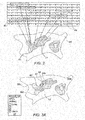
- Fig. 2 is a schematic, pictorial illustration of an electro-anatomical map of cardiac tissue overlaid with intra-cardiac locations that demonstrate regular AF activity, in accordance with an embodiment of the present invention.
- the processor indicates a location 51 as a location of regular AF activity, based on analyzing a respective annotated ECG time-segment 49 (i.e., that was recorded at the location).
- processor 28 determines, based on respective annotated ECG time-segment 49, that the average and SD of the AFCL value calculated for time-segment 49 are within the limits given above.
- Processor 28 then overlays each of locations 51 and the respectively calculated average AFCL value at each location 51 on map 55 for further processing into a gradient map, as described below.
- Figs. 3A and 3B are a schematic, pictorial illustration of an AFCL gradient maps 55a and 55b, respectively, of a portion of cardiac tissue, in accordance with embodiments of the present invention. Maps 55a and 55b may be presented to a user on display 26 of mapping system 20.
- maps 55a and 55b denote spatial location over cardiac tissue.
- maps 55a and 55b are of the left atrium of heart 23.
- Fig. 3A shows an isochronal map 55a, in which the displayed gray levels describe a varying value of the local average AFCL, are overlaid on an anatomical map, to indicate a local direction and size of the AFCL gradients.
- a legend 56 provides gray-level coding of the displayed average AFCL values. In an embodiment 100 mSec represents "Short” and 250 mSec represents “Long.” Contours 53 indicate the iso-value AFCL (e.g., by means of presentation of a topographic map).
- an "inner,” darkly shaded, region 52 has a shortest average AFCL.
- Lightly shaded, "Perimetrical" regions 58A, 58B and 58C have longest average AFCL values. In between, there are regions with intermediate shades and, correspondingly, intermediate average AFCL values. The changing shades are thus indicative of the size and direction of the AFCL gradients.
- the positive difference in regular in AFCL value between region 58 and region 52 indicates that activation propagates from location 52 towards location 58A.
- other indications such as the anatomical nature of the locations, and, for example, the value of the AFCL at region 52, may indicate that location 52 is a potential source of AF.
- physician 27 may consider this location as a potential source of AF and potential target for ablation
- Path 54 indicates a likely propagation route and direction of any AF activity originating at location 52.
- location 52 is in a pulmonary vein
- location 58 is at the left atrium
- location 57 is at the ostium of the pulmonary vein.
- a location 57 on path 54 may be a candidate location for an ablation, so as to cut off AF propagation from location 52 to location 58A.
- Fig. 3B is a vector map 55b, which displays minor gradient vectors 60 and major gradient vectors 62, overlaid on anatomical map 55. The darker and thicker part of the vectors are aligned at a direction of the vector point at.
- minor gradient vectors 60 are calculated from a set of regular AFCL locations 51 on map 55 having regular AFCL values (shown in Fig. 2 ). Each minor gradient vector 60 is an average of two differences over a triangle defined by three-neighboring locations (not shown) of the set of locations 51.
- a major gradient vector 62 is an average of two or more minor gradient vectors. As seen, both the isochronal map and the vector map indicate of a similar path through which an AF propagates over tissue of the depicted left atrium anatomy.
- Figs. 3A and 3B are chosen purely for the sake of simplicity and conceptual clarity. Visual elements that emphasize potential locations and paths of AF activation may be included, as well as numbers, such as a regular AFCL value displayed at each location.
- an animated AFCL Gradient propagation map (not shown), dynamically demonstrates the changes of AFCL over the anatomy, for example on display 26.
- Fig. 3B is presented overlaid on Fig. 3A , e.g., having vectors 60 are overlaid on the grey-level shading to indicate a local direction and size of the AFCL gradients.
- Fig. 3 is a flow chart that schematically illustrates a method for generating and using an AFCL gradient map 55b, in accordance with an embodiment of the present invention.
- the process of generating AFCL gradient map 55b begins by processor 28 uploading sets of AFCL values of corresponding locations over cardiac tissue, at an AFCL files uploading step 70.
- Processor 28 applies statistical analysis to each of the AFCL sets, so as to determine regular patterns of AF, at an AFCL analysis step 72.
- processor 28 calculates AFCL gradients between pairs of average AFCL values of adjacent locations 51, and constructs AFCL gradient map 55b, at an AFCL gradient mapping step 74.
- processor 28 overlays on map 55b AF arrows comprising size and direction (i.e., vectors) of AFCL gradients, at an arrow overlaying step 76.
- the arrows are indicative of locations at which the AF originates, or through which the AF propagates.
- the process may continue to display map 55b with the additional indications of an aberrant cardiac activity at cardiac locations, on display 48.
- processor 28 generates an animation of the AFCL values of successive propagating electrical activation events.
- processor 28 generates an animation of the AFCL values of successive propagating electrical activation events.
Landscapes
- Health & Medical Sciences (AREA)
- Life Sciences & Earth Sciences (AREA)
- Cardiology (AREA)
- Engineering & Computer Science (AREA)
- Surgery (AREA)
- Public Health (AREA)
- Heart & Thoracic Surgery (AREA)
- Medical Informatics (AREA)
- Molecular Biology (AREA)
- Animal Behavior & Ethology (AREA)
- General Health & Medical Sciences (AREA)
- Biomedical Technology (AREA)
- Veterinary Medicine (AREA)
- Physics & Mathematics (AREA)
- Pathology (AREA)
- Biophysics (AREA)
- Physiology (AREA)
- Otolaryngology (AREA)
- Nuclear Medicine, Radiotherapy & Molecular Imaging (AREA)
- Plasma & Fusion (AREA)
- Computer Vision & Pattern Recognition (AREA)
- Psychiatry (AREA)
- Signal Processing (AREA)
- Artificial Intelligence (AREA)
- Measurement And Recording Of Electrical Phenomena And Electrical Characteristics Of The Living Body (AREA)
- Saccharide Compounds (AREA)
Abstract
Description
- The present invention relates generally to intrabody electrophysiological mapping using probes, and particularly to cardiac electro-anatomical mapping.
- Invasive cardiac procedures often employ techniques for mapping electro-anatomical properties of cardiac tissue. For example,
U.S. Patent Application Publication 2005/0288599 describes systems and methods to assist in locating the focus of an atrial fibrillation. The systems and methods include the association of atrial fibrillation cycle length values and statistics relating thereto with temporal locations on an electrogram of a given electrode, and/or the coordination of electrode locations with respective the spectral analyses of electrogram signals and further parameters and statistics relating thereto. Ablation therapy can proceed under guidance of such information. - As another example, International Patent Application Publication
PCT/US2016/045483 describes cardiac mapping catheters and methods for using the catheters. The catheter can detect the presence, direction and/or source of a depolarization wave front associated with cardiac arrhythmia. A mapping catheter includes a plurality of bipolar electrode pairs in which the members of each pair are opposed to one another across a perimeter, for instance in a circular pattern. The spaced arrangement of the electrodes can be utilized to identify directional paths of moving electric fields or wave fronts in any direction passing across the endocardial surface. The catheters can be used to identify locations and types of triggers and/or drivers of cardiac arrhythmia including rotors, ectopic trigger foci and/or to delineate reentrant pathways. -
U.S. Patent Application Publication 2003/0023130 describes a method for identifying and localizing a reentrant circuit isthmus in a heart of a subject during sinus rhythm, including: a) receiving electrogram signals from the heart during sinus rhythm via electrodes; b) storing the electrogram signals; c) creating a map based on the electrogram signals; d) finding a center reference activation location on the map; e) defining measurement vectors originating from the center reference activation location; f) selecting from the measurement vectors a primary axis vector indicating a location of the reentrant circuit isthmus in the heart; g) finding threshold points of electrogram signals on the map; h) connecting the threshold points to form a polygon indicating a shape of the reentrant circuit isthmus in the heart. -
U.S. Patent Application Publication 2017/0202515 describes a method of atrial rotational activity pattern (RAP) source detection that includes detecting, via a plurality of sensors, electro-cardiogram (ECG) signals over time, each ECG signal detected via one of the plurality of sensors and indicating electrical activity of a heart. The method also includes determining, for each of the plurality of ECG signals, one or more local activation times (LATs) each indicating a time of activation of a corresponding ECG signal. The method further includes detecting whether one or more RAP source areas of activation in the heart is indicated based on the detected ECG signals and the one or more local LATs. Mapping information of the detected RAP source areas of activation in the heart is also generated for providing one or more maps. - An embodiment of the present invention provides a method including calculating, at multiple intra-cardiac locations, respective average atrial fibrillation cycle-length (AFCL) values. A determination is made as to whether the calculated average AFCL values are indicative of a regular atrial fibrillation (AF) activity. Gradients between pairs of the average AFCL values are calculated for a plurality of average AFCL values that are determined to be indicative of regular AF activity. The calculated AFCL gradients are presented to a user, overlaid on a map of at least a portion of the heart.
- In some embodiments, the method includes checking whether the average AFCL value is between a preset lower limit and a preset upper limit. In some embodiments, the method includes checking whether a standard deviation (SD) of the average AFCL value is smaller than a preset SD limit.
- In an embodiment, the method includes calculating an AFCL gradient for a pair of average AFCL values that were derived from electrocardiograms acquired at different times. In another embodiment, the method includes color-coding the AFCL gradients according to at least sizes and directions of the AFCL gradients.
- In some embodiments, the method includes denoting on the map arrows indicative of locations at which the AF originates, or through which the AF propagates. In some embodiments, the method includes displaying on the map an animation comprising at least one of initiation and propagation of the regular AF activity.
- In an embodiment, the method further includes comprising presenting the average AFCL values to the user, overlaid on the map. In another embodiment, the method includes color-coding locations on the map according to the average AFCL values at the locations.
- There is additionally provided, in accordance with an embodiment of the present invention, a system including a memory and a processor. The memory is configured to store atrial fibrillation cycle-length (AFCL) values corresponding to respective multiple intra-cardiac locations. The processor is configured to calculate from the stored AFCL values, average AFCL values at the respective multiple intra-cardiac locations, and to determine whether the calculated average AFCL values are indicative of a regular atrial fibrillation (AF) activity. The processor is further configured to, for a plurality of average AFCL values that are determined to be indicative of regular AF activity, calculate gradients between pairs of the average AFCL values, and to present the calculated AFCL gradients to a user, overlaid on a map of at least a portion of the heart.
- The present invention will be more fully understood from the following detailed description of the embodiments thereof, taken together with the drawings in which:
-
-
Fig. 1 is a schematic, pictorial illustration of a cardiac electro-anatomical mapping system, in accordance with an embodiment of the present invention; -
Fig. 2 is a schematic, pictorial illustration of an electro-anatomical map of cardiac tissue overlaid with intra-cardiac locations that demonstrate regular AF activity, in accordance with an embodiment of the present invention; -
Figs. 3A and3B are schematic, pictorial illustrations of AFCL gradient maps of a portion of cardiac tissue, in accordance with embodiments of the present invention; and -
Fig. 4 is a flow chart that schematically illustrates a method for generating and using an AFCL gradient map, in accordance with an embodiment of the present invention. - Embodiments of the present invention that are described hereinafter provide improved methods and systems for the electrophysiological (EP) characterization, and electro-anatomical mapping, of atrial fibrillation (AF). The disclosed techniques are applicable to the characterization and mapping of various types of aberrant cardiac EP activity, such as paroxysmal AF, persistent AF, or long-standing AF.
- The disclosed techniques utilize an empirical observation that the AFCL is variable among various anatomical locations, and over time at a same location as well. Nevertheless, AFCL is regular at locations of AF activation origin (drivers) and becomes less regular as activation propagates away from those locations. In the present context, a regular pattern of arrhythmia is characterized as having a regular, i.e., relatively unchanging, as defined below, AF cycle-length (AFCL) value. An AFCL value (not necessarily a regular one) refers to a time interval between two electrical activation events at a certain intra-cardiac location (e.g., on a surface of a cavity of the heart).
- An example catheter-based system and technique for automatically identifying activations and calculating AFCL values from intra-cardiac electrograms that exhibit AF or other arrhythmic behavior at a respective intra-cardiac location is described in
U.S. Patent application 15/986,238 - In some embodiments described herein, a processor first determines whether a characteristic regular AFCL value exists at each of multiple intra-cardiac locations that are electro-anatomically mapped. In some embodiments, the processor determines the existence of a regular AFCL value at a given intra-cardiac location based on performing statistical analysis over a set of AFCL values, which, for example, the processor calculates at the location using the method described in
U.S. Patent application 15/986,238 , cited above. Another method for identifying AF activations, which is based on unipolar electrocardiogram signals, is described inU.S. Patent application publication 2018/0042504 , entitled "Annotation of a Wavefront," filed February 15, 2018, whose disclosure is incorporated herein by reference. In an embodiment, the processor determines, for each distribution (i.e., set) of AFCL values (a) whether the average AFCL value lies between a preset lower limit and a preset upper limit, and (b) whether a standard deviation (SD) of the average AFCL value is smaller than a preset SD limit. - In some embodiments of the present invention, a processor retrieves sets of AFCL values by uploading "AFCL files," each file containing a set of calculated AFCL values for every given intra-cardiac location. Next, as described above, the processor calculates, for each set, the average AFCL value and its SD, so as to determine whether a regular pattern of arrythmia exists at each of the locations. In an embodiment, the processor displays, to a user, the determined regular average AFCL values, overlaid on an anatomical map of at least a portion of a heart of a patient.
- The disclosed embodiments further utilize another empirical observation, that gradients of regular AF patterns are well correlated with, and thus indicative of, useful clinical information, e.g., the directions of AF wave fronts propagation, the locations of activation origins (drivers, sources) over tissue of AF activation, as well as the regular patterns of the AF activation. In other words, the regular AFCL gradient is indicative and predicts AF wavelets and activation patterns in the heart chamber. For example, a positive regular AFCL gradient between a location at one of the pulmonary veins and a location at the left atrium may indicate an AF originating from the pulmonary vein and propagating into the left atrium. In such a case, the regular AFCL gradient map may indicate which pulmonary vein to isolate.
- In an embodiment, the processor calculates regular AFCL gradients (i.e., the sizes and directions of differences between AFCL averages of neighboring locations over cardiac tissue). Next, the processor generates an electro-anatomical map depicting the AFCL gradients overlaid on at least a portion of the heart. Finally, the processor presents to a user the gradient map (i.e., gradients, size, and direction that are overlaid on an anatomical map of at least a portion of a heart of a patient).
- In some embodiments, the processor emphasizes the AFCL averages and gradients on the map using one or more graphical schemes, such as color coding of intra-cardiac locations according to respective gradient values and/or directions, and/or average AFCL values at the locations. In an embodiment, the processor displays an animation of an initiation and/or propagation of a regular AF activity, by showing, for example, dynamic (i.e., transient) color coding of regular AFCL values overlaid on a map of at least a portion of the heart. In some embodiments, the processor provides the gradient information in the form of vectors, which are overlaid on the map.
- The disclosed AFCL gradient map is highly useful as a tool in assisting diagnosis of AF. In contrast to other AF mapping schemes which necessitate simultaneous recording of electrical signals from multiple locations of atria, e.g., mapping based on Local Activation Times (LAT) or phase analysis, the AFCL gradient map is much easier to obtain. Other AF mapping schemes have a significant limitation of collecting electrical data simultaneously from the entire heart chamber, as there is no, so far, a sufficient catheter enabling that precisely. Moreover, applying the approach of regional simultaneous mapping faces the inability to stich the mapped regions to produce a single, consistent, map, because there is no consistent reference that could be used in AF, in contrast to regular arrhythmias such as Atrial Flutter or Atrial Tachycardia.
- An AFCL gradient map, on the other hand, may be derived computationally from a set of electrocardiograms collected by a single regular mapping catheter; e.g., a linear or multi electrode catheter. The collected electrical data at each location is analyzed independently of other locations and later all these locations are combined according to AFCL regularity. Using this approach, the disclosed regular AFCL Gradient method enables combining (stitching) AF electrical data at various anatomical locations which were not collected simultaneously. In an embodiment, an AFCL gradient is calculated that way using for a pair of average AFCL values that were derived from electrocardiograms acquired at different times.
- Thus, the disclosed AFCL gradient mapping technique may simplify the mapping of AF by minimizing invasive probing required during the diagnostic procedure, eliminating the need for simultaneous recording and overcoming its limitations.
-
Fig. 1 is a schematic, pictorial illustration of a cardiac electro-anatomical mapping system 20, in accordance with an embodiment of the present invention. In some embodiments,system 20 is configured to acquire intra-cardiac electrograms from multiple intra-cardiac locations (of aheart 23 of a patient 25) and to analyze the electrograms to determine which of the locations demonstrate a regular CL of AF, as described above. For example,system 20 is configured to calculate, analyze, and display amap 55 of regular AFCL averages and/or gradients of the regular AFCL averages, so as to indicate locations of potential origin of the arrhythmia over cardiac tissue for potential treatment of the arrhythmia, such as by ablation. -
System 20 typically acquires the electrograms using acatheter 29, such as the Lasso® or Pentaray® catheters (both produced by Biosense-Webster, Irvine, California), which comprise multiple distal-electrodes 22 fitted at a distal-end 31. The acquired electrograms can be derived from bipolar signals and/or from unipolar signals. In bipolar acquisition, the signal represents the voltage between a respective pair of distal-electrodes 22. In unipolar acquisition, the signal represents the voltage between one of distal-electrodes 22 and a reference electrode that is coupled externally topatient 25. - The signals are transmitted to a
processor 28 via anelectrical interface 33 to which a proximal end ofcatheter 29 is connected.Processor 28 calculates from the electrograms, at each intra-cardiac location, a respective set of AFCL values, based on activation annotations of bipolar or unipolar signals. In some embodiments,processor 28 stores the different sets of the calculated AFCL values in AF annotation files 50 in amemory 44, wherein eachAF annotation file 50 contains a set of AFCL values derived from a distinct intra-cardiac location, to be further analyzed to determine if regular AF activity occurs at each location. - As noted above, a catheter-based system and technique that automatically identify AF activations and enables calculating AFCL values from intra-cardiac electrograms exhibiting atrial fibrillation or other arrhythmic behavior is provided by
U.S. Patent application 15/986,238 , cited above. - In some embodiments,
processor 28 calculates, from each of the sets of AFCL values in AF annotation files 50, an average AFCL and a standard-deviation (SD) of the average AFCL at the intra-cardiac location. If the average AFCL value at the location falls between preset lower and upper limits, such as 100 mSec < average AFCL < 300 mSec, and if its SD is smaller than a preset SD value, such as SD < 30 mSec, the processor categorizes the intra-cardiac location as a location where a regular pattern of AF occurs. The processor further assigns to that location the calculated average AFCL value, for example, for presentation in an electro-anatomical map. In an embodiment, for improving the analysis, the system may ignore extreme values of AFCL, as below 10 percentile and above 90 percentiles. - In some embodiments, for example, in long recording sections of 20-30 sec, regular patterns may appear for several seconds and in different events throughout the recorded section, with variability in SD among these events. In this case the determination of regularity, average AFCL and SD for each event could be made by
processor 28 calculating these parameters in a moving time window of 2-3 sec, for example. Thenprocessor 28 selects only the most regular time segment (e.g., based on minimal SD), and drops the remaining segments, even if the AFCL parameters of one or more of the other segments are within the limits. - In some embodiments,
processor 28 calculates AFCL gradients in order to generateAFCL gradient map 55 of at least part of the intra-cardiac tissue ofheart 23 ofpatient 25. In an embodiment,processor 28 overlays, at respective locations onmap 55, the calculated gradients (e.g., in form of vectors) to indicate where an AF may originate or through which it may propagate. In another embodiment, the processor storesAFCL gradient map 55 inmemory 44. -
Processor 28 is further configured to presentAFCL gradient map 55 on adisplay 26. For example, the processor displays a completed portion ofAFCL gradient map 55 while the rest of the map is still being calculated. - In general,
processor 28 may be embodied as a single processor, or as a cooperatively networked or clustered set of processors running software enabling the processor to perform the tasks described herein. The software may be downloaded toprocessor 28 in electronic form, over a network, for example, or it may, alternatively or additionally, be provided and/or stored on non-transitory tangible media, such as magnetic, optical, or electronic memory. -
Fig. 2 is a schematic, pictorial illustration of an electro-anatomical map of cardiac tissue overlaid with intra-cardiac locations that demonstrate regular AF activity, in accordance with an embodiment of the present invention. In some embodiments, as noted above, the processor indicates alocation 51 as a location of regular AF activity, based on analyzing a respective annotated ECG time-segment 49 (i.e., that was recorded at the location). In an embodiment,processor 28 determines, based on respective annotated ECG time-segment 49, that the average and SD of the AFCL value calculated for time-segment 49 are within the limits given above. -
Processor 28 then overlays each oflocations 51 and the respectively calculated average AFCL value at eachlocation 51 onmap 55 for further processing into a gradient map, as described below. -
Figs. 3A and3B are a schematic, pictorial illustration of anAFCL gradient maps Maps display 26 ofmapping system 20. - The horizontal and vertical directions of
maps Figs. 3A and3B , maps 55a and 55b are of the left atrium ofheart 23. -
Fig. 3A shows anisochronal map 55a, in which the displayed gray levels describe a varying value of the local average AFCL, are overlaid on an anatomical map, to indicate a local direction and size of the AFCL gradients. Alegend 56 provides gray-level coding of the displayed average AFCL values. In an embodiment 100 mSec represents "Short" and 250 mSec represents "Long."Contours 53 indicate the iso-value AFCL (e.g., by means of presentation of a topographic map). - As seen in
Fig. 3A , an "inner," darkly shaded,region 52 has a shortest average AFCL. Lightly shaded, "Perimetrical" regions 58A, 58B and 58C have longest average AFCL values. In between, there are regions with intermediate shades and, correspondingly, intermediate average AFCL values. The changing shades are thus indicative of the size and direction of the AFCL gradients. - Multiple activation points around
region 52, asFigs. 3A and3B indicate, with activation propagating fromregion 52 "outwards" to perimeter locations (as seen in the vector mapFig. 3B ) indicates that a regular AF activation is originating atregion 52. - By way of example, the positive difference in regular in AFCL value between region 58 and
region 52, combined with other indications, such as the anatomical nature of the locations, the width and number of shaded regions, and the value of the short AFCL (i.e., at region 52), indicates that activation propagates fromlocation 52 towards location 58A. Combined with other indications, such as the anatomical nature of the locations, and, for example, the value of the AFCL atregion 52, may indicate thatlocation 52 is a potential source of AF. Based on the indication,physician 27 may consider this location as a potential source of AF and potential target for ablation -
Path 54 indicates a likely propagation route and direction of any AF activity originating atlocation 52. In an embodiment,location 52 is in a pulmonary vein, location 58 is at the left atrium, andlocation 57 is at the ostium of the pulmonary vein. By way of example, alocation 57 onpath 54 may be a candidate location for an ablation, so as to cut off AF propagation fromlocation 52 to location 58A. -
Fig. 3B is avector map 55b, which displaysminor gradient vectors 60 andmajor gradient vectors 62, overlaid onanatomical map 55. The darker and thicker part of the vectors are aligned at a direction of the vector point at. In an embodiment,minor gradient vectors 60 are calculated from a set ofregular AFCL locations 51 onmap 55 having regular AFCL values (shown inFig. 2 ). Eachminor gradient vector 60 is an average of two differences over a triangle defined by three-neighboring locations (not shown) of the set oflocations 51. Amajor gradient vector 62 is an average of two or more minor gradient vectors. As seen, both the isochronal map and the vector map indicate of a similar path through which an AF propagates over tissue of the depicted left atrium anatomy. - The example illustration shown in
Figs. 3A and3B are chosen purely for the sake of simplicity and conceptual clarity. Visual elements that emphasize potential locations and paths of AF activation may be included, as well as numbers, such as a regular AFCL value displayed at each location. In an embodiment, an animated AFCL Gradient propagation map (not shown), dynamically demonstrates the changes of AFCL over the anatomy, for example ondisplay 26. - In some embodiments,
Fig. 3B is presented overlaid onFig. 3A , e.g., havingvectors 60 are overlaid on the grey-level shading to indicate a local direction and size of the AFCL gradients. -
Fig. 3 is a flow chart that schematically illustrates a method for generating and using anAFCL gradient map 55b, in accordance with an embodiment of the present invention. The process of generatingAFCL gradient map 55b begins byprocessor 28 uploading sets of AFCL values of corresponding locations over cardiac tissue, at an AFCL files uploadingstep 70. -
Processor 28 applies statistical analysis to each of the AFCL sets, so as to determine regular patterns of AF, at anAFCL analysis step 72. Next,processor 28 calculates AFCL gradients between pairs of average AFCL values ofadjacent locations 51, and constructsAFCL gradient map 55b, at an AFCLgradient mapping step 74. Finally,processor 28 overlays onmap 55b AF arrows comprising size and direction (i.e., vectors) of AFCL gradients, at anarrow overlaying step 76. The arrows are indicative of locations at which the AF originates, or through which the AF propagates. The process may continue to displaymap 55b with the additional indications of an aberrant cardiac activity at cardiac locations, on display 48. - The example flow chart shown in
Fig. 3 is chosen purely for the sake of conceptual clarity. In alternative embodiments, for example,processor 28 generates an animation of the AFCL values of successive propagating electrical activation events. Although the embodiments described herein mainly address specific cardiac applications, the methods and systems described herein can also be used in other cardiac applications. - It will thus be appreciated that the embodiments described above are cited by way of example, and that the present invention is not limited to what has been particularly shown and described hereinabove. Rather, the scope of the present invention includes both combinations and sub-combinations of the various features described hereinabove, as well as variations and modifications thereof which would occur to persons skilled in the art upon reading the foregoing description and which are not disclosed in the prior art. Documents incorporated by reference in the present patent application are to be considered an integral part of the application except that to the extent any terms are defined in these incorporated documents in a manner that conflicts with the definitions made explicitly or implicitly in the present specification, only the definitions in the present specification should be considered.
Claims (18)
- A method, comprising:calculating, at multiple intra-cardiac locations, respective average atrial fibrillation cycle-length (AFCL) values;determining whether the calculated average AFCL values are indicative of a regular atrial fibrillation (AF) activity;for a plurality of average AFCL values that are determined to be indicative of regular AF activity, calculating gradients between pairs of the average AFCL values; andpresenting the calculated AFCL gradients to a user, overlaid on a map of at least a portion of the heart.
- The method according to claim 1, wherein determining whether an average AFCL value is indicative of regular AF activity comprises checking whether the average AFCL value is between a preset lower limit and a preset upper limit.
- The method according to claim 1, wherein determining whether an average AFCL value is indicative of regular AF activity comprises checking whether a standard deviation (SD) of the average AFCL value is smaller than a preset SD limit.
- The method according to claim 1, wherein calculating the gradients comprises calculating an AFCL gradient for a pair of average AFCL values that were derived from electrocardiograms acquired at different times.
- The method according to claim 1, wherein presenting the AFCL gradients comprises color-coding the AFCL gradients according to at least sizes and directions of the AFCL gradients.
- The method according to claim 1, wherein presenting the AFCL gradients comprises denoting on the map arrows indicative of locations at which the AF originates, or through which the AF propagates.
- The method according to claim 1, wherein presenting the AFCL gradients comprises displaying on the map an animation comprising at least one of initiation and propagation of the regular AF activity.
- The method according to claim 1, and comprising presenting the average AFCL values to the user, overlaid on the map.
- The method according to claim 8, wherein presenting the average AFCL values comprises color-coding locations on the map according to the average AFCL values at the locations.
- A system, comprising:a memory, which is configured to store atrial fibrillation cycle-length (AFCL) values corresponding to respective multiple intra-cardiac locations; anda processor, which is configured to:calculate from the stored AFCL values, average AFCL values at the respective multiple intra-cardiac locations;determine whether the calculated average AFCL values are indicative of a regular atrial fibrillation (AF) activity;for a plurality of average AFCL values that are determined to be indicative of regular AF activity, calculate gradients between pairs of the average AFCL values; andpresent the calculated AFCL gradients to a user, overlaid on a map of at least a portion of the heart.
- The system according to claim 10, wherein the processor is configured to determine whether an average AFCL value is indicative of regular AF activity by checking whether the average AFCL value is between a preset lower limit and a preset upper limit.
- The system according to claim 10, wherein the processor is configured to determine whether an average AFCL value is indicative of regular AF activity by checking whether a standard deviation (SD) of the average AFCL value is smaller than a preset SD limit.
- The system according to claim 10, wherein the processor is configured to calculate an AFCL gradient for a pair of average AFCL values that were derived from electrocardiograms acquired at different times.
- The system according to claim 10, wherein the processor is configured to present the AFCL gradients by color-coding the AFCL gradients according to at least sizes and directions of the AFCL gradients.
- The method according to claim 10, wherein the processor is configured to present the AFCL gradients by denoting on the map arrows indicative of locations at which the AF originates, or through which the AF propagates.
- The system according to claim 10, wherein the processor is configured to present the AFCL gradients by displaying on the map an animation comprising at least one of initiation and propagation of the regular AF activity.
- The system according to claim 10, wherein the processor is further configured to present the average AFCL values to the user, overlaid on the map.
- The system according to claim 10, wherein the processor is configured to present the average AFCL values by color-coding locations on the map according to the average AFCL values at the locations.
Applications Claiming Priority (1)
| Application Number | Priority Date | Filing Date | Title |
|---|---|---|---|
| US16/108,863 US11160481B2 (en) | 2018-08-22 | 2018-08-22 | Atrial fibrillation mapping using atrial fibrillation cycle length (AFCL) gradients |
Publications (3)
| Publication Number | Publication Date |
|---|---|
| EP3613342A1 true EP3613342A1 (en) | 2020-02-26 |
| EP3613342C0 EP3613342C0 (en) | 2024-07-31 |
| EP3613342B1 EP3613342B1 (en) | 2024-07-31 |
Family
ID=67704487
Family Applications (1)
| Application Number | Title | Priority Date | Filing Date |
|---|---|---|---|
| EP19192897.7A Active EP3613342B1 (en) | 2018-08-22 | 2019-08-21 | Atrial fibrillation mapping using atrial fibrillation cycle length (afcl) gradients |
Country Status (7)
| Country | Link |
|---|---|
| US (1) | US11160481B2 (en) |
| EP (1) | EP3613342B1 (en) |
| JP (1) | JP7408317B2 (en) |
| CN (1) | CN110974218B (en) |
| AU (1) | AU2019219823A1 (en) |
| CA (1) | CA3052601A1 (en) |
| IL (1) | IL268741B (en) |
Cited By (2)
| Publication number | Priority date | Publication date | Assignee | Title |
|---|---|---|---|---|
| US12310737B2 (en) | 2020-09-30 | 2025-05-27 | Boston Scientific Scimed, Inc. | Interactive 2D scatter plot of EGM characteristic metrics |
| US12471828B2 (en) | 2020-09-30 | 2025-11-18 | Boston Scientific Scimed, Inc. | Electrophysiology system and method for determining local cycle length and local duty cycle |
Families Citing this family (7)
| Publication number | Priority date | Publication date | Assignee | Title |
|---|---|---|---|---|
| JP7175333B2 (en) * | 2018-09-10 | 2022-11-18 | セント・ジュード・メディカル,カーディオロジー・ディヴィジョン,インコーポレイテッド | Systems and methods for displaying electrophysiological signals from multidimensional catheters |
| US11445935B2 (en) * | 2018-11-26 | 2022-09-20 | Biosense Webster (Israel) Ltd. | Finding the origin of an arrythmia |
| CN111436927A (en) * | 2020-04-23 | 2020-07-24 | 无锡市人民医院 | A Circumference Mapping Method for Atrial Fibrillation |
| CN111739631B (en) * | 2020-06-19 | 2024-08-23 | 首都医科大学附属北京潞河医院 | Electrocardiogram-based processing method and system |
| US12082881B2 (en) * | 2021-03-22 | 2024-09-10 | Biosense Webster (Israel) Ltd. | Visualizing multiple parameters overlaid on an anatomical map |
| US20230263452A1 (en) * | 2022-02-22 | 2023-08-24 | Biosense Webster (Israel) Ltd. | Automatic storage and display of ecg signals indicative of atrial fibrillation |
| GB2630761A (en) * | 2023-06-06 | 2024-12-11 | Rhythm Ai Ltd | Computer implemented method and system for aiding mapping heart rhythm abnormalities |
Citations (5)
| Publication number | Priority date | Publication date | Assignee | Title |
|---|---|---|---|---|
| US20030023130A1 (en) | 2001-07-30 | 2003-01-30 | Ciaccio Edward J. | System and method for determining reentrant ventricular tachycardia isthmus and shape for catheter ablation |
| US20050288599A1 (en) | 2004-05-17 | 2005-12-29 | C.R. Bard, Inc. | High density atrial fibrillation cycle length (AFCL) detection and mapping system |
| WO2015120064A1 (en) * | 2014-02-04 | 2015-08-13 | Cardioinsight Technologies, Inc. | Integrated analysis of electrophysiological data |
| US20170202515A1 (en) | 2016-01-14 | 2017-07-20 | Biosense Webster (Israel) Ltd. | Region of interest rotational activity pattern detection |
| US20180042504A1 (en) | 2016-08-11 | 2018-02-15 | Biosense Webster (Israel) Ltd. | Annotation of a wavefront |
Family Cites Families (14)
| Publication number | Priority date | Publication date | Assignee | Title |
|---|---|---|---|---|
| US6016442A (en) * | 1998-03-25 | 2000-01-18 | Cardiac Pacemakers, Inc. | System for displaying cardiac arrhythmia data |
| US6496731B1 (en) * | 2000-04-14 | 2002-12-17 | Cardiac Pacemakers, Inc. | Highly specific technique for discriminating atrial fibrillation from atrial flutter |
| US7233822B2 (en) * | 2004-06-29 | 2007-06-19 | Medtronic, Inc. | Combination of electrogram and intra-cardiac pressure to discriminate between fibrillation and tachycardia |
| US7537569B2 (en) * | 2005-04-29 | 2009-05-26 | Medtronic, Inc. | Method and apparatus for detection of tachyarrhythmia using cycle lengths |
| AU2009302220B2 (en) * | 2008-10-09 | 2014-03-27 | The Regents Of The University Of California | Methods, system and apparatus for the detection, diagnosis and treatment of biological rhythm disorders |
| US10398326B2 (en) * | 2013-03-15 | 2019-09-03 | The Regents Of The University Of California | System and method of identifying sources associated with biological rhythm disorders |
| US8965496B2 (en) * | 2010-09-27 | 2015-02-24 | Steven J. Bailin | Method for determining the location of regions in tissue relevant to electrical propagation |
| US9642550B2 (en) * | 2013-05-03 | 2017-05-09 | Northwestern University | Cycle length iteration for the detection of atrial activations from electrogram recordings of atrial fibrillation |
| US11172832B2 (en) * | 2014-06-02 | 2021-11-16 | Cardiac Pacemakers, Inc. | Systems and methods for evaluating hemodynamic response to atrial fibrillation |
| JP6320634B2 (en) * | 2014-10-15 | 2018-05-09 | セント・ジュード・メディカル,カーディオロジー・ディヴィジョン,インコーポレイテッド | Method and system for mapping local conduction velocities |
| EP3258843A4 (en) * | 2015-02-19 | 2018-09-26 | CardioInsight Technologies, Inc. | Signal characterization for detecting and/or analyzing driver activity |
| US10631749B2 (en) | 2015-08-06 | 2020-04-28 | Health Sciences Center, Llc | Devices and methods for mapping cardiac arrhythmia |
| US20170202521A1 (en) * | 2016-01-14 | 2017-07-20 | Biosense Webster (Israel) Ltd. | Overall system and method for detecting regions of interest |
| EP3528702B1 (en) * | 2016-10-18 | 2025-05-21 | Cardiac Pacemakers, Inc. | System for arrhythmia detection |
-
2018
- 2018-08-22 US US16/108,863 patent/US11160481B2/en active Active
-
2019
- 2019-08-15 IL IL268741A patent/IL268741B/en unknown
- 2019-08-21 EP EP19192897.7A patent/EP3613342B1/en active Active
- 2019-08-21 JP JP2019150998A patent/JP7408317B2/en active Active
- 2019-08-21 CA CA3052601A patent/CA3052601A1/en not_active Abandoned
- 2019-08-22 CN CN201910778277.XA patent/CN110974218B/en active Active
- 2019-08-22 AU AU2019219823A patent/AU2019219823A1/en not_active Abandoned
Patent Citations (5)
| Publication number | Priority date | Publication date | Assignee | Title |
|---|---|---|---|---|
| US20030023130A1 (en) | 2001-07-30 | 2003-01-30 | Ciaccio Edward J. | System and method for determining reentrant ventricular tachycardia isthmus and shape for catheter ablation |
| US20050288599A1 (en) | 2004-05-17 | 2005-12-29 | C.R. Bard, Inc. | High density atrial fibrillation cycle length (AFCL) detection and mapping system |
| WO2015120064A1 (en) * | 2014-02-04 | 2015-08-13 | Cardioinsight Technologies, Inc. | Integrated analysis of electrophysiological data |
| US20170202515A1 (en) | 2016-01-14 | 2017-07-20 | Biosense Webster (Israel) Ltd. | Region of interest rotational activity pattern detection |
| US20180042504A1 (en) | 2016-08-11 | 2018-02-15 | Biosense Webster (Israel) Ltd. | Annotation of a wavefront |
Non-Patent Citations (2)
| Title |
|---|
| SANJIV M. NARAYAN ET AL: "Evaluating Fluctuations in Human Atrial Fibrillatory Cycle Length Using Monophasic Action Potentials", PACE - PACING AND CLINICAL ELECTROPHYSIOLOGY., vol. 29, no. 11, 1 November 2006 (2006-11-01), US, pages 1209 - 1218, XP055416706, ISSN: 0147-8389, DOI: 10.1111/j.1540-8159.2006.00525.x * |
| SEUNGYUP LEE ET AL: "An Algorithm to Measure Beat-to-Beat Cycle Lengths for Assessment of Atrial Electrogram Rate and Regularity During Atrial Fibrillation", JOURNAL OF CARDIOVASCULAR ELECTROPHYSIOLOGY., vol. 24, no. 2, 9 February 2013 (2013-02-09), US, pages 199 - 206, XP055335908, ISSN: 1045-3873, DOI: 10.1111/jce.12014 * |
Cited By (2)
| Publication number | Priority date | Publication date | Assignee | Title |
|---|---|---|---|---|
| US12310737B2 (en) | 2020-09-30 | 2025-05-27 | Boston Scientific Scimed, Inc. | Interactive 2D scatter plot of EGM characteristic metrics |
| US12471828B2 (en) | 2020-09-30 | 2025-11-18 | Boston Scientific Scimed, Inc. | Electrophysiology system and method for determining local cycle length and local duty cycle |
Also Published As
| Publication number | Publication date |
|---|---|
| EP3613342C0 (en) | 2024-07-31 |
| IL268741B (en) | 2022-08-01 |
| AU2019219823A1 (en) | 2020-03-12 |
| CN110974218B (en) | 2024-06-18 |
| CA3052601A1 (en) | 2020-02-22 |
| EP3613342B1 (en) | 2024-07-31 |
| CN110974218A (en) | 2020-04-10 |
| JP2020028713A (en) | 2020-02-27 |
| US11160481B2 (en) | 2021-11-02 |
| JP7408317B2 (en) | 2024-01-05 |
| US20200060567A1 (en) | 2020-02-27 |
| IL268741A (en) | 2020-02-27 |
Similar Documents
| Publication | Publication Date | Title |
|---|---|---|
| EP3613342B1 (en) | Atrial fibrillation mapping using atrial fibrillation cycle length (afcl) gradients | |
| US12285259B2 (en) | Identification and visualization of cardiac activation sequence in multi-channel recordings | |
| JP5553319B2 (en) | Imaging device for imaging the heart | |
| EP3639736B1 (en) | Method for mapping ventricular/atrial premature beats during sinus rhythm | |
| EP3015060B1 (en) | Real-time coloring of electrophysiological map | |
| CN115151191B (en) | Computer-implemented methods and systems for assisting in mapping cardiac rhythm abnormalities | |
| CN112401901B (en) | Electroanatomical map re-annotation | |
| Koutalas et al. | Contemporary mapping techniques of complex cardiac arrhythmias–identifying and modifying the arrhythmogenic substrate | |
| EP3705037A1 (en) | Mid-field signal extraction | |
| US20220369991A1 (en) | Medical apparatus for diagnostic and site determination of cardiac arrhythmias and methods | |
| WO2024127164A1 (en) | Using signed distance functions to visualize pulsed field ablation (pfa) tags | |
| JP7669137B2 (en) | Mapping regional activation times during sinus and non-sinus rhythm cardiac cycles | |
| EP4518761B1 (en) | Detecting potential slow-conduction cardiac tissue areas in stable arrhythmias | |
| EP3669767B1 (en) | Visualization of different cardiac rhythms using different timing-pattern displays | |
| EP3614913B1 (en) | Connectivity analysis for arrhythmia drivers | |
| Sun et al. | New High‐Density and Automated Mapping Systems |
Legal Events
| Date | Code | Title | Description |
|---|---|---|---|
| PUAI | Public reference made under article 153(3) epc to a published international application that has entered the european phase |
Free format text: ORIGINAL CODE: 0009012 |
|
| STAA | Information on the status of an ep patent application or granted ep patent |
Free format text: STATUS: THE APPLICATION HAS BEEN PUBLISHED |
|
| AK | Designated contracting states |
Kind code of ref document: A1 Designated state(s): AL AT BE BG CH CY CZ DE DK EE ES FI FR GB GR HR HU IE IS IT LI LT LU LV MC MK MT NL NO PL PT RO RS SE SI SK SM TR |
|
| AX | Request for extension of the european patent |
Extension state: BA ME |
|
| STAA | Information on the status of an ep patent application or granted ep patent |
Free format text: STATUS: REQUEST FOR EXAMINATION WAS MADE |
|
| 17P | Request for examination filed |
Effective date: 20200811 |
|
| RBV | Designated contracting states (corrected) |
Designated state(s): AL AT BE BG CH CY CZ DE DK EE ES FI FR GB GR HR HU IE IS IT LI LT LU LV MC MK MT NL NO PL PT RO RS SE SI SK SM TR |
|
| STAA | Information on the status of an ep patent application or granted ep patent |
Free format text: STATUS: EXAMINATION IS IN PROGRESS |
|
| 17Q | First examination report despatched |
Effective date: 20220223 |
|
| REG | Reference to a national code |
Ref country code: DE Ref legal event code: R079 Free format text: PREVIOUS MAIN CLASS: A61B0005040000 Ipc: A61B0005361000 Ref country code: DE Ref legal event code: R079 Ref document number: 602019056019 Country of ref document: DE Free format text: PREVIOUS MAIN CLASS: A61B0005040000 Ipc: A61B0005361000 |
|
| RIC1 | Information provided on ipc code assigned before grant |
Ipc: A61B 5/361 20210101AFI20230726BHEP |
|
| GRAP | Despatch of communication of intention to grant a patent |
Free format text: ORIGINAL CODE: EPIDOSNIGR1 |
|
| STAA | Information on the status of an ep patent application or granted ep patent |
Free format text: STATUS: GRANT OF PATENT IS INTENDED |
|
| INTG | Intention to grant announced |
Effective date: 20230911 |
|
| GRAJ | Information related to disapproval of communication of intention to grant by the applicant or resumption of examination proceedings by the epo deleted |
Free format text: ORIGINAL CODE: EPIDOSDIGR1 |
|
| STAA | Information on the status of an ep patent application or granted ep patent |
Free format text: STATUS: EXAMINATION IS IN PROGRESS |
|
| GRAP | Despatch of communication of intention to grant a patent |
Free format text: ORIGINAL CODE: EPIDOSNIGR1 |
|
| STAA | Information on the status of an ep patent application or granted ep patent |
Free format text: STATUS: GRANT OF PATENT IS INTENDED |
|
| INTC | Intention to grant announced (deleted) | ||
| INTG | Intention to grant announced |
Effective date: 20240222 |
|
| GRAS | Grant fee paid |
Free format text: ORIGINAL CODE: EPIDOSNIGR3 |
|
| GRAA | (expected) grant |
Free format text: ORIGINAL CODE: 0009210 |
|
| STAA | Information on the status of an ep patent application or granted ep patent |
Free format text: STATUS: THE PATENT HAS BEEN GRANTED |
|
| AK | Designated contracting states |
Kind code of ref document: B1 Designated state(s): AL AT BE BG CH CY CZ DE DK EE ES FI FR GB GR HR HU IE IS IT LI LT LU LV MC MK MT NL NO PL PT RO RS SE SI SK SM TR |
|
| REG | Reference to a national code |
Ref country code: CH Ref legal event code: EP Ref country code: GB Ref legal event code: FG4D |
|
| REG | Reference to a national code |
Ref country code: DE Ref legal event code: R096 Ref document number: 602019056019 Country of ref document: DE |
|
| REG | Reference to a national code |
Ref country code: IE Ref legal event code: FG4D |
|
| U01 | Request for unitary effect filed |
Effective date: 20240816 |
|
| U07 | Unitary effect registered |
Designated state(s): AT BE BG DE DK EE FI FR IT LT LU LV MT NL PT RO SE SI Effective date: 20240902 |
|
| U20 | Renewal fee for the european patent with unitary effect paid |
Year of fee payment: 6 Effective date: 20240902 |
|
| PG25 | Lapsed in a contracting state [announced via postgrant information from national office to epo] |
Ref country code: NO Free format text: LAPSE BECAUSE OF FAILURE TO SUBMIT A TRANSLATION OF THE DESCRIPTION OR TO PAY THE FEE WITHIN THE PRESCRIBED TIME-LIMIT Effective date: 20241031 |
|
| PG25 | Lapsed in a contracting state [announced via postgrant information from national office to epo] |
Ref country code: GR Free format text: LAPSE BECAUSE OF FAILURE TO SUBMIT A TRANSLATION OF THE DESCRIPTION OR TO PAY THE FEE WITHIN THE PRESCRIBED TIME-LIMIT Effective date: 20241101 Ref country code: PL Free format text: LAPSE BECAUSE OF FAILURE TO SUBMIT A TRANSLATION OF THE DESCRIPTION OR TO PAY THE FEE WITHIN THE PRESCRIBED TIME-LIMIT Effective date: 20240731 |
|
| PG25 | Lapsed in a contracting state [announced via postgrant information from national office to epo] |
Ref country code: IS Free format text: LAPSE BECAUSE OF FAILURE TO SUBMIT A TRANSLATION OF THE DESCRIPTION OR TO PAY THE FEE WITHIN THE PRESCRIBED TIME-LIMIT Effective date: 20241130 |
|
| PG25 | Lapsed in a contracting state [announced via postgrant information from national office to epo] |
Ref country code: HR Free format text: LAPSE BECAUSE OF FAILURE TO SUBMIT A TRANSLATION OF THE DESCRIPTION OR TO PAY THE FEE WITHIN THE PRESCRIBED TIME-LIMIT Effective date: 20240731 |
|
| PG25 | Lapsed in a contracting state [announced via postgrant information from national office to epo] |
Ref country code: ES Free format text: LAPSE BECAUSE OF FAILURE TO SUBMIT A TRANSLATION OF THE DESCRIPTION OR TO PAY THE FEE WITHIN THE PRESCRIBED TIME-LIMIT Effective date: 20240731 Ref country code: RS Free format text: LAPSE BECAUSE OF FAILURE TO SUBMIT A TRANSLATION OF THE DESCRIPTION OR TO PAY THE FEE WITHIN THE PRESCRIBED TIME-LIMIT Effective date: 20241031 |
|
| PG25 | Lapsed in a contracting state [announced via postgrant information from national office to epo] |
Ref country code: RS Free format text: LAPSE BECAUSE OF FAILURE TO SUBMIT A TRANSLATION OF THE DESCRIPTION OR TO PAY THE FEE WITHIN THE PRESCRIBED TIME-LIMIT Effective date: 20241031 Ref country code: PL Free format text: LAPSE BECAUSE OF FAILURE TO SUBMIT A TRANSLATION OF THE DESCRIPTION OR TO PAY THE FEE WITHIN THE PRESCRIBED TIME-LIMIT Effective date: 20240731 Ref country code: NO Free format text: LAPSE BECAUSE OF FAILURE TO SUBMIT A TRANSLATION OF THE DESCRIPTION OR TO PAY THE FEE WITHIN THE PRESCRIBED TIME-LIMIT Effective date: 20241031 Ref country code: IS Free format text: LAPSE BECAUSE OF FAILURE TO SUBMIT A TRANSLATION OF THE DESCRIPTION OR TO PAY THE FEE WITHIN THE PRESCRIBED TIME-LIMIT Effective date: 20241130 Ref country code: HR Free format text: LAPSE BECAUSE OF FAILURE TO SUBMIT A TRANSLATION OF THE DESCRIPTION OR TO PAY THE FEE WITHIN THE PRESCRIBED TIME-LIMIT Effective date: 20240731 Ref country code: GR Free format text: LAPSE BECAUSE OF FAILURE TO SUBMIT A TRANSLATION OF THE DESCRIPTION OR TO PAY THE FEE WITHIN THE PRESCRIBED TIME-LIMIT Effective date: 20241101 Ref country code: ES Free format text: LAPSE BECAUSE OF FAILURE TO SUBMIT A TRANSLATION OF THE DESCRIPTION OR TO PAY THE FEE WITHIN THE PRESCRIBED TIME-LIMIT Effective date: 20240731 |
|
| REG | Reference to a national code |
Ref country code: CH Ref legal event code: PL |
|
| PG25 | Lapsed in a contracting state [announced via postgrant information from national office to epo] |
Ref country code: SM Free format text: LAPSE BECAUSE OF FAILURE TO SUBMIT A TRANSLATION OF THE DESCRIPTION OR TO PAY THE FEE WITHIN THE PRESCRIBED TIME-LIMIT Effective date: 20240731 |
|
| PG25 | Lapsed in a contracting state [announced via postgrant information from national office to epo] |
Ref country code: MC Free format text: LAPSE BECAUSE OF FAILURE TO SUBMIT A TRANSLATION OF THE DESCRIPTION OR TO PAY THE FEE WITHIN THE PRESCRIBED TIME-LIMIT Effective date: 20240731 Ref country code: CH Free format text: LAPSE BECAUSE OF NON-PAYMENT OF DUE FEES Effective date: 20240831 |
|
| PG25 | Lapsed in a contracting state [announced via postgrant information from national office to epo] |
Ref country code: CZ Free format text: LAPSE BECAUSE OF FAILURE TO SUBMIT A TRANSLATION OF THE DESCRIPTION OR TO PAY THE FEE WITHIN THE PRESCRIBED TIME-LIMIT Effective date: 20240731 |
|
| PG25 | Lapsed in a contracting state [announced via postgrant information from national office to epo] |
Ref country code: SK Free format text: LAPSE BECAUSE OF FAILURE TO SUBMIT A TRANSLATION OF THE DESCRIPTION OR TO PAY THE FEE WITHIN THE PRESCRIBED TIME-LIMIT Effective date: 20240731 |
|
| PLBE | No opposition filed within time limit |
Free format text: ORIGINAL CODE: 0009261 |
|
| STAA | Information on the status of an ep patent application or granted ep patent |
Free format text: STATUS: NO OPPOSITION FILED WITHIN TIME LIMIT |
|
| 26N | No opposition filed |
Effective date: 20250501 |
|
| PG25 | Lapsed in a contracting state [announced via postgrant information from national office to epo] |
Ref country code: IE Free format text: LAPSE BECAUSE OF NON-PAYMENT OF DUE FEES Effective date: 20240821 |
|
| U20 | Renewal fee for the european patent with unitary effect paid |
Year of fee payment: 7 Effective date: 20250709 |
|
| PGFP | Annual fee paid to national office [announced via postgrant information from national office to epo] |
Ref country code: GB Payment date: 20250703 Year of fee payment: 7 |
|
| PG25 | Lapsed in a contracting state [announced via postgrant information from national office to epo] |
Ref country code: CY Free format text: LAPSE BECAUSE OF FAILURE TO SUBMIT A TRANSLATION OF THE DESCRIPTION OR TO PAY THE FEE WITHIN THE PRESCRIBED TIME-LIMIT; INVALID AB INITIO Effective date: 20190821 |
|
| PG25 | Lapsed in a contracting state [announced via postgrant information from national office to epo] |
Ref country code: HU Free format text: LAPSE BECAUSE OF FAILURE TO SUBMIT A TRANSLATION OF THE DESCRIPTION OR TO PAY THE FEE WITHIN THE PRESCRIBED TIME-LIMIT; INVALID AB INITIO Effective date: 20190821 |