EP3613315A1 - Compressing mattresses to reduce volume without causing permanent damage - Google Patents
Compressing mattresses to reduce volume without causing permanent damage Download PDFInfo
- Publication number
- EP3613315A1 EP3613315A1 EP19250009.8A EP19250009A EP3613315A1 EP 3613315 A1 EP3613315 A1 EP 3613315A1 EP 19250009 A EP19250009 A EP 19250009A EP 3613315 A1 EP3613315 A1 EP 3613315A1
- Authority
- EP
- European Patent Office
- Prior art keywords
- mattresses
- restraining
- compressed
- mattress
- compression
- Prior art date
- Legal status (The legal status is an assumption and is not a legal conclusion. Google has not performed a legal analysis and makes no representation as to the accuracy of the status listed.)
- Withdrawn
Links
Images






Classifications
-
- A—HUMAN NECESSITIES
- A47—FURNITURE; DOMESTIC ARTICLES OR APPLIANCES; COFFEE MILLS; SPICE MILLS; SUCTION CLEANERS IN GENERAL
- A47C—CHAIRS; SOFAS; BEDS
- A47C27/00—Spring, stuffed or fluid mattresses or cushions specially adapted for chairs, beds or sofas
- A47C27/04—Spring, stuffed or fluid mattresses or cushions specially adapted for chairs, beds or sofas with spring inlays
-
- B—PERFORMING OPERATIONS; TRANSPORTING
- B65—CONVEYING; PACKING; STORING; HANDLING THIN OR FILAMENTARY MATERIAL
- B65B—MACHINES, APPARATUS OR DEVICES FOR, OR METHODS OF, PACKAGING ARTICLES OR MATERIALS; UNPACKING
- B65B63/00—Auxiliary devices, not otherwise provided for, for operating on articles or materials to be packaged
- B65B63/02—Auxiliary devices, not otherwise provided for, for operating on articles or materials to be packaged for compressing or compacting articles or materials prior to wrapping or insertion in containers or receptacles
-
- B—PERFORMING OPERATIONS; TRANSPORTING
- B65—CONVEYING; PACKING; STORING; HANDLING THIN OR FILAMENTARY MATERIAL
- B65B—MACHINES, APPARATUS OR DEVICES FOR, OR METHODS OF, PACKAGING ARTICLES OR MATERIALS; UNPACKING
- B65B13/00—Bundling articles
- B65B13/18—Details of, or auxiliary devices used in, bundling machines or bundling tools
- B65B13/20—Means for compressing or compacting bundles prior to bundling
-
- B—PERFORMING OPERATIONS; TRANSPORTING
- B65—CONVEYING; PACKING; STORING; HANDLING THIN OR FILAMENTARY MATERIAL
- B65B—MACHINES, APPARATUS OR DEVICES FOR, OR METHODS OF, PACKAGING ARTICLES OR MATERIALS; UNPACKING
- B65B35/00—Supplying, feeding, arranging or orientating articles to be packaged
- B65B35/30—Arranging and feeding articles in groups
- B65B35/50—Stacking one article, or group of articles, upon another before packaging
-
- B—PERFORMING OPERATIONS; TRANSPORTING
- B65—CONVEYING; PACKING; STORING; HANDLING THIN OR FILAMENTARY MATERIAL
- B65D—CONTAINERS FOR STORAGE OR TRANSPORT OF ARTICLES OR MATERIALS, e.g. BAGS, BARRELS, BOTTLES, BOXES, CANS, CARTONS, CRATES, DRUMS, JARS, TANKS, HOPPERS, FORWARDING CONTAINERS; ACCESSORIES, CLOSURES, OR FITTINGS THEREFOR; PACKAGING ELEMENTS; PACKAGES
- B65D85/00—Containers, packaging elements or packages, specially adapted for particular articles or materials
- B65D85/07—Containers, packaging elements or packages, specially adapted for particular articles or materials for compressible or flexible articles
Definitions
- the present invention relates to a method of compressing mattresses to reduce volume without causing permanent damage.
- the present invention also relates to an apparatus for compressing mattresses to reduce volume without causing permanent damage.
- spring subassemblies of mattresses may be compressed by a rolling or baling operation performed at the end of a recycling process.
- spring subassemblies consisting exclusively of steel components with all fabric removed, may be compressed and rolled; given that any subsequent recycling operations will be conducted within a metal recycling facility.
- techniques of this type when deployed against complete mattresses, cause significant damage to internal components of the mattress which creates substantial difficulties within a mattress recycling facility.
- known techniques for compression may be deployed when a mattress is to be directed towards landfill but known techniques for compression should not be deployed when mattresses are being stored or transported for recycling purposes.
- the compressing of new mattresses to reduce volume to facilitate transportation is only possible if the compression can be achieved without introducing permanent damage. A problem therefore exists in terms of how to compress a complete mattress for storage or transportation purposes to a significant degree, without causing permanent damage.
- an apparatus for compressing mattresses to reduce volume without causing permanent damage comprising: a compression device; and a transportation frame, wherein: said transportation frame is arranged to receive a mattress stack of mattresses stacked with support surfaces in contact to a predetermined height; and said compression device is configured to apply additional mattresses, compress said additional mattresses in a direction substantially normal to said support surfaces to produce a compressed mattress stack and restrain said compressed mattress stack by restraining means.
- a method of compressing mattresses to reduce volume without causing permanent damage comprising the steps of: stacking a plurality of mattresses, with support surfaces being substantially in contact, to produce a mattress stack; applying pressure substantially in the direction of said mattress stack, such that said pressure is normal to the support surfaces and consistent with pressure applied by a reclining body, thereby resulting in reversible compression to form a compressed mattress stack; and restraining said compressed mattress stack.
- the restraining step includes the application of a temporary restraining device during a compression process.
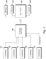
- FIG. 1 An environment for the collection, storage and recycling of mattresses is illustrated in Figure 1 .
- the environment includes collection facilities and, in Figure 1 , a first collection facility 101 is shown, along with a second collection facility 102 , a third collection facility 103 , a fourth collection facility 104 and a fifth collection facility 105 .
- a collection facility could be operated by a local council or could be supported by a particular retailer, allowing the retailer to remove and recycle old mattress when new ones are being supplied.
- mattresses are transported from the collection facilities to a storage buffer 106 implemented as a warehousing facility close to a recycling plant 107 .
- An aim of the operator of the recycling plant 107 is to maintain continual operation of the plant, therefore the plant requires a continual stream of old mattresses from the storage buffer.
- Bailing machines are known that roll mattresses up and then apply a retaining device, such as a plastic sock, to retain the mattresses in a rolled state.
- a retaining device such as a plastic sock
- this approach distorts the shape of the mattress, making it difficult to recycle.
- the mattress itself in order to strip a mattress, the mattress itself must be laid flat.
- the present embodiment aims to compress mattresses to an extent that, for example, allows five-hundred to five-hundred-and-fifty mattresses to be carried by a single lorry, that previously could only carry eighty to one-hundred mattresses. However, this is achieved in a way that does not cause permanent damage, such that the process may be reversed and the recycling operations performed as if the mattress had not been compressed.
- compression takes place at each of the collection facilities 101 to 105 , thereby allowing significantly more mattresses to be transferred to the storage buffer 106 .
- the mattresses are stored in their compressed configuration at the storage buffer 106 until they are required by the recycling plant 107 . This allows substantially more mattresses to be held at the storage buffer 106 .
- the recycling plant 107 must produce some waste 108 but an aim of the recycling plant operator is to reduce this as far as possible. Thus, materials are recovered from the recycling process, including metals 109 and fabrics 110 .
- a collection facility such as the first collection facility 101 , is illustrated in Figure 2 , having received discarded mattresses for recycling purposes.
- the mattresses are initially stored in non-compressed stacks.
- a first mattress stack 201 includes a first mattress 211 , a second mattress 212 , a third mattress 213 , a fourth mattress 214 , a fifth mattress 215 , a sixth mattress 216 , a seventh mattress 217 , an eighth mattress 218 and a ninth mattress 219 .
- the first collection facility also includes a second mattress stack 202 and a third mattress stack 203 .
- Each mattress has edge portions 231 connecting a larger upper support surface 232 and a similar lower support surface. As shown in Figure 2 , stacking involves placing support surfaces of adjacent mattresses substantially in contact.
- a method is performed of compressing mattresses to reduce volume without causing permanent damage, as illustrated in Figure 3 .
- mattresses are stacked, with support surfaces being substantially in contact, to produce a mattress stack.
- pressure is applied substantially in the direction of the mattress stack, such that this pressure is normal to the support surfaces and is consistent with the pressure that would have been applied by a reclining body, thereby resulting in a reversible compression to form a compressed mattress stack.
- the compressed mattress stack is restrained.
- a restrained and compressed mattress stack it is possible for a restrained and compressed mattress stack to be transported from the first collection facility 101 to the storage buffer 106 .
- the mattress in this compressed and restrained form, it is possible for the mattress to be stored at the storage buffer 106 until required by the recycling plant 107 .
- the restraining step includes the application of a temporary restraining device during a compression process. This is then replaced with a permanent restraining device for transportation and storage.
- a base 401 receives uncompressed mattresses. To facilitate transportation of mattresses within the collection facility, the mattresses are transported in groups of three. Thus, in this way, mattresses 211 to 219 of the first mattress stack 201 are transported onto the base 401 , as illustrated in Figure 4 .
- a compression device in the form of a compression press 501 , is brought down on top of the upper support surface 232 of the top mattress 219 .
- a compression press in the form of a compression press 501 .
- pressure is applied to compress the mattress stack 201 to a height that is slightly below the position of a retaining device 601 .
- the retaining device 601 After compressing the mattress stack, as described with reference to Figure 6 , the retaining device 601 is moved in the direction of arrow 701 , to retain the compressed mattress stack in place.
- the retaining device 601 is received within grooves forming part of the compression press 501 , thereby allowing the retaining device 601 to be inserted while the compression press 501 remains in place.
- each group includes three mattresses to be compressed and a compression cycle involves fifteen of these groups, thereby compressing forty-five mattresses into the space usually occupied by six.
- a compression cycle involves fifteen of these groups, thereby compressing forty-five mattresses into the space usually occupied by six.
- alternative group sizes and different numbers of groups may be deployed.
- a stillage is inserted within the compression apparatus and, in this embodiment, six non-compressed mattresses (effectively two groups of three) are initially loaded into the stillage. It is likely that each collection facility would be provided with a single compression apparatus that remains resident. In addition, each collection facility would receive many stillages, which may be in a folded form to minimise their volume when not in use. The local compression apparatus is then used to compress mattresses within the stillages. When a sufficient number of stillages have been used, they are loaded onto a lorry and transported to the storage buffer 106 .
- each stillage when assembled, provides an empty steel frame with forklift truck locations at its bottom.
- many empty stillages may be transported and dropped off.
- a stillage is lifted into place by a fork lift truck.
- a door of the compression apparatus is closed and delivery conveyers are provided to the side of the compression apparatus for receiving the uncompressed mattresses.
- the stillages also have feet on the bottom and nubs on the top, thereby allowing them to be stacked two high. In this way, it is possible for a trailer to receive twelve of these stillages, each typically containing forty-five mattresses, thereby allowing a total of five-hundred-and-forty mattresses to be transported.
- the stillages are designed to take the largest mattresses of six-by-six feet. In addition, this also allows single mattresses to be placed side-by-side but it is appreciated that some gaps will be present if smaller double mattresses are to be compressed. Other embodiments may be configured to take larger mattresses.
- the configuration of the mattress stack is substantially similar to that shown in Figure 4 .
- the mattress stack is compressed.
- the press 501 is brought down, as described with reference to Figure 5 and pressure is applied to compress the mattress stack as described with reference to Figure 6 .
- the retaining device 601 is moved in the direction of arrow 701 , to retain the compressed stack, as described with reference to Figure 7 and the compression press 501 is then retracted, as described with reference to Figure 8 .
- the compressed mattress stack is retained by the retaining device 601 .
- the restraining device 601 is a temporary restraining device forming part of the compression apparatus.
- the compressed stack is restrained temporarily, as shown at step 904 .
- step 905 a question is asked as to whether another group is to be compressed and when answered in the affirmative, the next group is loaded at step 906 .
- step 907 the press is lowered to restrain the mattresses and the temporary restraining device is then removed at step 908 . Thereafter, step 903 is repeated to achieve further compression, followed by temporary restraint at step 904 .
- the compressed mattresses have been restrained temporarily at step 904 , as illustrated in Figure 8 .
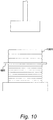
- the next group of mattresses are loaded at step 906 , as illustrated in Figure 10 .
- a next group 1001 of uncompressed mattresses has been loaded upon the temporary restraining device 601 .
- the press 501 is lowered in the direction of arrow 1101 , following step 907 .
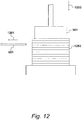
- the temporary restraining device 601 is retracted in the direction of arrow 1201 , in accordance with step 908 .
- the full enhanced compressed stack 1202 is retained by the compression press 501 .
- a further cycle of compression is then performed, such that the press 501 is moved further in the direction of arrow 1203 , to achieve a configuration sustainably similar to that described with reference to Figure 6 .
- the temporary retaining device is again activated, substantially as described with reference to Figure 7 , allowing the press 501 to be retracted, substantially as described with reference to Figure 8 .
- the next group of mattresses may be loaded as described with reference to Figure 10 and the overall process repeated, until the question asked at step 905 is answered in the negative.
- the method allows a third plurality of non-compressed mattresses to be placed upon the temporary restraining device, thereby allowing the compressing device to be brought into contact with this third plurality.
- the temporary restraining device is again retracted, allowing the compression device to further compress and thereby add the third plurality of mattresses to the first plurality of compressed mattresses.
- the temporary restraining device is again deployed to restrain the compressed mattresses and the compression device is again displaced away from the temporary restraining device, thereby allowing further mattresses to be introduced until a limit has been reached.
- the number of mattresses introduced for compression is preselected; irrespective of the actual thickness of the mattresses involved.
- the compression steps are repeated until a predetermined level of compression has been achieved and this predetermined level of compression may be determined by measuring the pressure of the compressed mattresses.
- the mattresses are supported within a transportable frame or stillage.
- the temporary restraining device forms part of the compression device and upon reaching a predetermined level of compression, the temporary restraining device is replaced by a permanent restraining device forming part of the transportable frame or stillage.
- Each mattress includes a first support surface, a second support surface and a surrounding edge, as previously described with reference to Figure 2 .
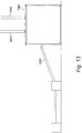
- the apparatus comprises a compression device 1301 and transportation frames or stillages.
- a collection facility will be provided with at least one compression device 1301 and a plurality of transportation frames.
- Each transportation frame is arranged to receive a mattress stack of mattresses, stacked with support surfaces in contact to a predetermined height, substantially as described with reference to Figure 4 .
- the compression device is configured to apply additional mattresses and compress the additional mattresses in a direction substantially normal to the support surfaces to produce a compressed mattress stack, as previously described with reference to Figure 6 . This compressed mattress stack is then restrained by restraining means, as described with reference to Figure 7 .
- the compression device is configured to compress the mattress stack to the predetermined height, being the height just below that of the temporary restraining device 601 , as described with reference to Figure 6 . Thereafter, the compression device is configured to repeatedly add non-compressed mattresses to the compressed stack.
- the compression device 1301 has twin hydraulic shafts, implemented as a first hydraulic shaft 1311 and a second hydraulic shaft 1312 .
- a conveyer 1313 receives a group (of three) mattresses and is then activated, such that the mattresses go up the conveyer and enter the compression device 1301 at an opening having a predetermined height.
- the mattresses are delivered onto the temporary retaining device, taking the form of parallel tubes at the top of the machine that are arranged to retract. These tubes locate within stillage holes present within the stillage, to provide the temporary restraint.
- mattresses may enter the machine and rest of top of the tubes.
- the tubes are retracted, so that the first group of mattresses drop below the level of the tubes.
- the tubes then go back over to allow the second group of three mattresses to be placed on top of the tubes.
- the tubes retract, such that the compression device now contains six mattresses, having a typical height of about one metre.
- a compression cycle is now performed, with three new mattresses being added to the six uncompressed mattresses currently in the stillage.
- the tubes are inserted again and the next three mattresses slide on top of the tubes. At this stage, six mattresses are below the tubes and three mattresses are supported by the tubes.
- the press 501 comes down and touches the top of the mattresses, as described with reference to Figure 5 .
- the tubes retract but the pressure applied maintains the mattresses in position.
- the compression device 1301 is shown in Figure 14 , having received a stillage 1401 .
- a compression platform 1402 is attached to the first hydraulic shaft 1311 and the second hydraulic shaft 1312 .
- the compression platform 1402 is shown in its upper position, such that a reception space 1403 is provided below the compression platform 1402 to receive additional non-compressed mattresses.
- the stillage 1401 includes horizontal side supports, including an uppermost horizontal side support 1404 .
- the uppermost horizontal side support 1403 includes stillage holes 1405 ; with eight stillage holes being present in the embodiment illustrated in Figure 14 .
- the stillage holes 1405 are arranged to receive eight parallel retention tubes which provide the temporary restraining device 601 .
- the compression device 1301 is shown in Figure 15 , with the compression platform 1402 in its lower position; in a configuration substantially similar to that described with reference to Figure 6 .
- the bottom of the compression platform 1402 includes accommodation channels 1501 , each of which is configured to align with a respective stillage hole 1405 when the compression platform 1402 is in its lower position.
- each stillage hole 1405 receives a retention tube, of the type described with reference to Figure 16 .
- the configuration is substantially similar to that described with respect to Figure 7 .
- the compression platform 1402 to move upwards in the direction of arrow 1502 , thereby returning the compression platform 1402 back to its upper position, as described with reference to Figure 14 .
- Outer surfaces of the retention tubes are bright and smooth in an embodiment, to facilitate the introduction of additional uncompressed mattresses within the reception space 1403 .
- the compression platform 1402 is then operated to move in the direction of arrow 1406 , thereby adopting a configuration substantially similar to that described with respect to Figure 11 .
- the retention tubes are retracted from the stillage holes 1405 , resulting in a configuration substantially similar to that described with respect to Figure 12 .
- Further compression is then conducted until the compression platform 1402 reaches its lower position, resulting in a further three mattresses being compressed within the storage space of the stillage.
- the compression platform 1402 is returned to its upper position, as described with reference to Figure 14 .
- FIG. 16 A side view of a part of the stillage 1401 is illustrated in Figure 16 . This shows a first stillage portion 1601 and a second stillage portion 1602 defining a stillage hole 1405 therebetween.
- each stillage hole 1405 receives a respective retention tube substantially similar to retention tube 1604 .
- the retention tubes (including retention tube 1604 ) only provide a temporary retaining device, of the type described with reference to Figure 7 .
- the retention tubes form part of the compression device and are therefore retained for the next compression cycle.
- each internal bore 1605 of a retention tube 1604 receives a respective retention rod.
- a retention rod 1606 is inserted within the internal bore 1605 in the direction of arrow 1607 .
- Each retention rod such as retention rod 1606
- a retention pin 1609 is inserted through a rod hole 1610 in order to secure the retention rod 1606 .
- the end of the retention rod 1606 could be threaded, for example, to receive an appropriate wingnut, in order to achieve a secured configuration.
- the retention tubes including retention tube 1604 , are removed.
- the mattresses 1603 under compression expand slightly in the direction of arrow 1701 but are still restrained within the stillage due to the presence of the retention rods, including retention rod 1606 .
- the retention pins 1608 are located within their respective rod holes 1609 to prevent movement of the retention rod in the direction of arrow 1702 . Furthermore, a retention head 1703 is provided at the opposite end of each retention pin 1608 to prevent movement of the retention rod 1606 in the direction of arrow 1704 .
- FIG. 18 A top view of a secured stillage ready for transportation is illustrated in Figure 18 .
- eight retention rods 1606 are in place, although the actual number may vary in order to achieve a required degree of retention while minimising the number of operations required to secure the stillage.
- each retention rod is secured by a retention head 1703 at a first end and a retention pin 1609 at the opposition end.
- the compressed mattresses When retained in a stillage of the type shown in Figure 18 , the compressed mattresses may be transported and stored in the storage buffer 106 . If required, the mattresses could be stored for a considerable period of time although, operationally, the storage buffer is provided to even out seasonal variations and is not intended as a long-term storage solution. Furthermore, the stillages are configured to be used repeatedly and, in an embodiment, collapse to occupy a much smaller volume when being stored or transported prior to deployment.
Landscapes
- Engineering & Computer Science (AREA)
- Mechanical Engineering (AREA)
- Refuse Collection And Transfer (AREA)
Abstract
Mattresses are stacked, with support surfaces being substantially in contact, to produce a mattress stack (201). A press (501) applies pressure in the direction of said mattress stack, such that said pressure is normal to the support surfaces and consistent with pressure applied by a reclining body, thereby resulting in reversible compression to form a compressed mattress stack. Restraining means (601) restrains the mattress stack and the process may be repeated to increase the size of the stack.
Description
- The present invention relates to a method of compressing mattresses to reduce volume without causing permanent damage. The present invention also relates to an apparatus for compressing mattresses to reduce volume without causing permanent damage.
- It is known to compress spring subassemblies of mattresses to reduce the volume occupied by these products. Spring subassemblies may be compressed by a rolling or baling operation performed at the end of a recycling process. Thus, spring subassemblies, consisting exclusively of steel components with all fabric removed, may be compressed and rolled; given that any subsequent recycling operations will be conducted within a metal recycling facility. However, techniques of this type when deployed against complete mattresses, cause significant damage to internal components of the mattress which creates substantial difficulties within a mattress recycling facility.
- Thus, known techniques for compression may be deployed when a mattress is to be directed towards landfill but known techniques for compression should not be deployed when mattresses are being stored or transported for recycling purposes. Furthermore, the compressing of new mattresses to reduce volume to facilitate transportation is only possible if the compression can be achieved without introducing permanent damage. A problem therefore exists in terms of how to compress a complete mattress for storage or transportation purposes to a significant degree, without causing permanent damage.
- According to a first aspect of the present invention, there is provided an apparatus for compressing mattresses to reduce volume without causing permanent damage, comprising: a compression device; and a transportation frame, wherein: said transportation frame is arranged to receive a mattress stack of mattresses stacked with support surfaces in contact to a predetermined height; and said compression device is configured to apply additional mattresses, compress said additional mattresses in a direction substantially normal to said support surfaces to produce a compressed mattress stack and restrain said compressed mattress stack by restraining means.
- According to a second aspect of the present invention, there is provided a method of compressing mattresses to reduce volume without causing permanent damage, comprising the steps of: stacking a plurality of mattresses, with support surfaces being substantially in contact, to produce a mattress stack; applying pressure substantially in the direction of said mattress stack, such that said pressure is normal to the support surfaces and consistent with pressure applied by a reclining body, thereby resulting in reversible compression to form a compressed mattress stack; and restraining said compressed mattress stack.
- In an embodiment, the restraining step includes the application of a temporary restraining device during a compression process.
- Embodiments of the invention will be described, by way of example only, with reference to the accompanying drawings. The detailed embodiments show the best mode known to the inventor and provide support for the invention as claimed. However, they are only exemplary and should not be used to interpret or limit the scope of the claims. Their purpose is to provide a teaching to those skilled in the art. Components and processes distinguished by ordinal phrases such as "first" and "second" do not necessarily define an order or ranking of any sort. In the drawings:
-
Figure 1 shows an environment for the collection, storage and recycling of mattresses; -
Figure 2 shows non-compressed stacks of mattresses; -
Figure 3 illustrates a method of compressing mattresses; -
Figure 4 shows a first stage of mattress compression; -
Figure 5 shows a second stage of mattress compression; -
Figure 6 shows a third stage of mattress compression; -
Figure 7 shows a fourth stage of mattress compression; -
Figure 8 shows a fifth stage of mattress compression; -
Figure 9 shows an enhanced procedure for compressing mattresses; -
Figure 10 shows a sixth stage of mattress compression; -
Figure 11 shows a seventh stage of mattress compression; -
Figure 12 shows an eighth stage of mattress compression; -
Figure 13 shows an apparatus for compressing mattresses; -
Figure 14 details a compression device identified inFigure 13 ; -
Figure 15 shows the compression device ofFigure 14 in an alternative configuration; -
Figure 16 shows a side view of a stillage identified inFigure 14 ; -
Figure 17 shows the stillage ofFigure 16 in an alternative configuration; and -
Figure 18 shows a top view of a secured stillage ready for transportation. - An environment for the collection, storage and recycling of mattresses is illustrated in
Figure 1 . The environment includes collection facilities and, inFigure 1 , afirst collection facility 101 is shown, along with asecond collection facility 102, athird collection facility 103, afourth collection facility 104 and afifth collection facility 105. In a typical deployment, a collection facility could be operated by a local council or could be supported by a particular retailer, allowing the retailer to remove and recycle old mattress when new ones are being supplied. - In the environment of
Figure 1 , mattresses are transported from the collection facilities to astorage buffer 106 implemented as a warehousing facility close to arecycling plant 107. An aim of the operator of therecycling plant 107 is to maintain continual operation of the plant, therefore the plant requires a continual stream of old mattresses from the storage buffer. - The majority of mattresses continue to be made from springs and as a result of this, they tend to retain their original shape. Articulated lorries (typically 40 feet in length) are used to transport used mattresses from collection facilities to the
storage buffer 106. In a lorry of this type, it is possible to get eighty to one-hundred-and-twenty mattresses loaded, with the resulting weight of the load being relatively low for a vehicle of this type. Consequently, the cost per unit mile is relatively high, placing limits on the length of acceptable transportation links between collection facilities and thestorage buffer 106. Consequently, in order to reduce the length of these transportation links, it would be necessary to have relatively many recycling plants receiving old mattresses from relatively few collection facilities. However, to make better use of recycling plants, it would be preferable for them to receive discarded mattresses from a larger geographical area, requiring a greater number of collection facilities but incurring significantly more transportation miles. - Bailing machines are known that roll mattresses up and then apply a retaining device, such as a plastic sock, to retain the mattresses in a rolled state. However, this approach distorts the shape of the mattress, making it difficult to recycle. For example, in order to strip a mattress, the mattress itself must be laid flat. However, after being rolled, it is not possible to obtain the original flat configuration.
- Many mattresses have a boarder rod with pocket springs or open coil springs. These boarder rods are either flat or cylindrical but once distorted, the whole mattress becomes distorted, making it difficult to recycle economically. Thus, any savings made by the compression of mattresses in this way is lost, due to the additional costs involved in terms of recycling them.
- The present embodiment aims to compress mattresses to an extent that, for example, allows five-hundred to five-hundred-and-fifty mattresses to be carried by a single lorry, that previously could only carry eighty to one-hundred mattresses. However, this is achieved in a way that does not cause permanent damage, such that the process may be reversed and the recycling operations performed as if the mattress had not been compressed.
- Thus, in the environment of
Figure 1 , compression takes place at each of thecollection facilities 101 to 105, thereby allowing significantly more mattresses to be transferred to thestorage buffer 106. The mattresses are stored in their compressed configuration at thestorage buffer 106 until they are required by therecycling plant 107. This allows substantially more mattresses to be held at thestorage buffer 106. - Experience shows that a significant number of mattresses appear for recycling during the winter months, with this number reducing through the summer. Thus, it is possible for an average mattress feed to be calculated and for the recycling plant to be optimised for this available feed. Fluctuations throughout the year are then buffered by the
storage buffer 106. - It is appreciated that the
recycling plant 107 must produce somewaste 108 but an aim of the recycling plant operator is to reduce this as far as possible. Thus, materials are recovered from the recycling process, includingmetals 109 andfabrics 110. - A collection facility, such as the
first collection facility 101, is illustrated inFigure 2 , having received discarded mattresses for recycling purposes. The mattresses are initially stored in non-compressed stacks. Thus, afirst mattress stack 201 includes afirst mattress 211, asecond mattress 212, athird mattress 213, afourth mattress 214, afifth mattress 215, asixth mattress 216, aseventh mattress 217, aneighth mattress 218 and aninth mattress 219. The first collection facility also includes asecond mattress stack 202 and athird mattress stack 203. Thus, it can be seen that a relatively low number of mattresses quickly start to take up a significant amount of space within thefirst collection facility 101. - Each mattress has
edge portions 231 connecting a largerupper support surface 232 and a similar lower support surface. As shown inFigure 2 , stacking involves placing support surfaces of adjacent mattresses substantially in contact. - In an embodiment, a method is performed of compressing mattresses to reduce volume without causing permanent damage, as illustrated in
Figure 3 . - At
step 301, mattresses are stacked, with support surfaces being substantially in contact, to produce a mattress stack. - At
step 302, pressure is applied substantially in the direction of the mattress stack, such that this pressure is normal to the support surfaces and is consistent with the pressure that would have been applied by a reclining body, thereby resulting in a reversible compression to form a compressed mattress stack. - Thereafter, at
step 303, the compressed mattress stack is restrained. In this way, it is possible for a restrained and compressed mattress stack to be transported from thefirst collection facility 101 to thestorage buffer 106. Furthermore, in this compressed and restrained form, it is possible for the mattress to be stored at thestorage buffer 106 until required by therecycling plant 107. In an embodiment, the restraining step includes the application of a temporary restraining device during a compression process. This is then replaced with a permanent restraining device for transportation and storage. - A first method of compressing mattresses to reduce volume without causing permanent damage will be described with reference to
Figures 4 to 8 . - A
base 401 receives uncompressed mattresses. To facilitate transportation of mattresses within the collection facility, the mattresses are transported in groups of three. Thus, in this way,mattresses 211 to 219 of thefirst mattress stack 201 are transported onto thebase 401, as illustrated inFigure 4 . - After assembling the
mattress stack 201, as described with reference toFigure 4 , a compression device, in the form of acompression press 501, is brought down on top of theupper support surface 232 of thetop mattress 219. Thus, no further mattresses may be added at this point and the stack 209 is retained in place without experiencing any pressure being applied thereto. - After aligning the
compression press 501, pressure is applied to compress themattress stack 201 to a height that is slightly below the position of aretaining device 601. - After compressing the mattress stack, as described with reference to
Figure 6 , the retainingdevice 601 is moved in the direction ofarrow 701, to retain the compressed mattress stack in place. The retainingdevice 601 is received within grooves forming part of thecompression press 501, thereby allowing the retainingdevice 601 to be inserted while thecompression press 501 remains in place. - With a compressed mattress stack retained in place by the retaining
device 601, as described with reference toFigure 7 , thepress 501 now retracts, in the direction ofarrow 801, back to the position illustrated inFigure 4 . - The compression procedure as described with references to
Figures 3 to 8 , provides a degree of compression that allows nine mattresses to occupy the space previously taken by six. However, given the construction of the mattresses, it is possible to achieve a greater level of compression without causing permanent damage. However, transportation within the facility is easier if the mattresses can be moved in groups of no more than three. Thus, a further embodiment seeks to achieve a higher level of compression while accepting the constraints of only transporting a limited number of uncompressed mattresses in any one movement. - An enhanced procedure for compressing mattresses to reduce volume without causing permanent damage is illustrated in
Figure 9 . Atstep 901, the mattresses are assembled into groups and compression then takes place on a group-by-group basis. In this embodiment, each group includes three mattresses to be compressed and a compression cycle involves fifteen of these groups, thereby compressing forty-five mattresses into the space usually occupied by six. However, it should be appreciated that in alternative configurations, alternative group sizes and different numbers of groups may be deployed. - At
step 902, a stillage is inserted within the compression apparatus and, in this embodiment, six non-compressed mattresses (effectively two groups of three) are initially loaded into the stillage. It is likely that each collection facility would be provided with a single compression apparatus that remains resident. In addition, each collection facility would receive many stillages, which may be in a folded form to minimise their volume when not in use. The local compression apparatus is then used to compress mattresses within the stillages. When a sufficient number of stillages have been used, they are loaded onto a lorry and transported to thestorage buffer 106. - In an embodiment, each stillage, when assembled, provides an empty steel frame with forklift truck locations at its bottom. In an embodiment, it is possible for the stillage to collapse down, to occupy significantly less volume. Thus, in this way, many empty stillages may be transported and dropped off.
- In use, a stillage is lifted into place by a fork lift truck. A door of the compression apparatus is closed and delivery conveyers are provided to the side of the compression apparatus for receiving the uncompressed mattresses.
- In an embodiment, the stillages also have feet on the bottom and nubs on the top, thereby allowing them to be stacked two high. In this way, it is possible for a trailer to receive twelve of these stillages, each typically containing forty-five mattresses, thereby allowing a total of five-hundred-and-forty mattresses to be transported.
- The stillages are designed to take the largest mattresses of six-by-six feet. In addition, this also allows single mattresses to be placed side-by-side but it is appreciated that some gaps will be present if smaller double mattresses are to be compressed. Other embodiments may be configured to take larger mattresses.
- After the insertion and loading of the stillage at
step 902, the configuration of the mattress stack is substantially similar to that shown inFigure 4 . - At
step 903 the mattress stack is compressed. Thus, thepress 501 is brought down, as described with reference toFigure 5 and pressure is applied to compress the mattress stack as described with reference toFigure 6 . Thereafter, the retainingdevice 601 is moved in the direction ofarrow 701, to retain the compressed stack, as described with reference toFigure 7 and thecompression press 501 is then retracted, as described with reference toFigure 8 . The compressed mattress stack is retained by the retainingdevice 601. - In this enhanced embodiment, the restraining
device 601 is a temporary restraining device forming part of the compression apparatus. Thus, the compressed stack is restrained temporarily, as shown atstep 904. - At
step 905, a question is asked as to whether another group is to be compressed and when answered in the affirmative, the next group is loaded atstep 906. Atstep 907, the press is lowered to restrain the mattresses and the temporary restraining device is then removed atstep 908. Thereafter,step 903 is repeated to achieve further compression, followed by temporary restraint atstep 904. - As the question asked at
step 905 continues to be answered in the affirmative, further mattresses are loaded and further compression takes place until the question asked atstep 905 has been answered in the negative. In this embodiment, fifteen groups of three mattresses will have been temporarily restrained before the question asked atstep 905 is answered in the negative. Again, other embodiments may be designed to hold fewer or more mattresses. - When the question asked at
step 905 is answered in the negative, a permanent restraint is deployed atstep 909 and the temporary restraint is removed atstep 910. The full stillage is then dispatched atstep 911 and a question is then asked atstep 912 as to whether more mattresses are to be compressed. Thus, when answered in the affirmative, further mattresses are assembled into groups atstep 901. - On a first iteration of the procedure described with reference to
Figure 9 , the compressed mattresses have been restrained temporarily atstep 904, as illustrated inFigure 8 . Following the question asked atstep 905 being answered in the affirmative, the next group of mattresses are loaded atstep 906, as illustrated inFigure 10 . Thus, in this way, anext group 1001 of uncompressed mattresses has been loaded upon thetemporary restraining device 601. - Following the loading of the next group of
mattresses 1001 upon thetemporary retaining device 601, thepress 501 is lowered in the direction ofarrow 1101, followingstep 907. - Following the deployment of the
compression press 501 atstep 907, thetemporary restraining device 601 is retracted in the direction ofarrow 1201, in accordance withstep 908. Thus, the full enhancedcompressed stack 1202 is retained by thecompression press 501. - As previously described, a further cycle of compression is then performed, such that the
press 501 is moved further in the direction ofarrow 1203, to achieve a configuration sustainably similar to that described with reference toFigure 6 . The temporary retaining device is again activated, substantially as described with reference toFigure 7 , allowing thepress 501 to be retracted, substantially as described with reference toFigure 8 . Thus, the next group of mattresses may be loaded as described with reference toFigure 10 and the overall process repeated, until the question asked atstep 905 is answered in the negative. - Thus, it can be seen that the method allows a third plurality of non-compressed mattresses to be placed upon the temporary restraining device, thereby allowing the compressing device to be brought into contact with this third plurality. The temporary restraining device is again retracted, allowing the compression device to further compress and thereby add the third plurality of mattresses to the first plurality of compressed mattresses. The temporary restraining device is again deployed to restrain the compressed mattresses and the compression device is again displaced away from the temporary restraining device, thereby allowing further mattresses to be introduced until a limit has been reached.
- In an embodiment, the number of mattresses introduced for compression is preselected; irrespective of the actual thickness of the mattresses involved. In an alternative embodiment, the compression steps are repeated until a predetermined level of compression has been achieved and this predetermined level of compression may be determined by measuring the pressure of the compressed mattresses.
- In this embodiment, the mattresses are supported within a transportable frame or stillage. The temporary restraining device forms part of the compression device and upon reaching a predetermined level of compression, the temporary restraining device is replaced by a permanent restraining device forming part of the transportable frame or stillage.
- An apparatus is illustrated in
Figure 13 for compressing mattresses to reduce volume without causing permanent damage, by implementing the method described previously. Each mattress includes a first support surface, a second support surface and a surrounding edge, as previously described with reference toFigure 2 . - The apparatus comprises a
compression device 1301 and transportation frames or stillages. In practice, a collection facility will be provided with at least onecompression device 1301 and a plurality of transportation frames. Each transportation frame is arranged to receive a mattress stack of mattresses, stacked with support surfaces in contact to a predetermined height, substantially as described with reference toFigure 4 . The compression device is configured to apply additional mattresses and compress the additional mattresses in a direction substantially normal to the support surfaces to produce a compressed mattress stack, as previously described with reference toFigure 6 . This compressed mattress stack is then restrained by restraining means, as described with reference toFigure 7 . - In this way, the compression device is configured to compress the mattress stack to the predetermined height, being the height just below that of the
temporary restraining device 601, as described with reference toFigure 6 . Thereafter, the compression device is configured to repeatedly add non-compressed mattresses to the compressed stack. - The
compression device 1301 has twin hydraulic shafts, implemented as a firsthydraulic shaft 1311 and a secondhydraulic shaft 1312. A conveyer 1313 receives a group (of three) mattresses and is then activated, such that the mattresses go up the conveyer and enter thecompression device 1301 at an opening having a predetermined height. The mattresses are delivered onto the temporary retaining device, taking the form of parallel tubes at the top of the machine that are arranged to retract. These tubes locate within stillage holes present within the stillage, to provide the temporary restraint. - Initially, mattresses may enter the machine and rest of top of the tubes. The tubes are retracted, so that the first group of mattresses drop below the level of the tubes. The tubes then go back over to allow the second group of three mattresses to be placed on top of the tubes. Again, the tubes retract, such that the compression device now contains six mattresses, having a typical height of about one metre. A compression cycle is now performed, with three new mattresses being added to the six uncompressed mattresses currently in the stillage.
- The tubes are inserted again and the next three mattresses slide on top of the tubes. At this stage, six mattresses are below the tubes and three mattresses are supported by the tubes. The
press 501 comes down and touches the top of the mattresses, as described with reference toFigure 5 . The tubes retract but the pressure applied maintains the mattresses in position. - The
compression device 1301 is shown inFigure 14 , having received astillage 1401. Acompression platform 1402 is attached to the firsthydraulic shaft 1311 and the secondhydraulic shaft 1312. Thecompression platform 1402 is shown in its upper position, such that areception space 1403 is provided below thecompression platform 1402 to receive additional non-compressed mattresses. - The
stillage 1401 includes horizontal side supports, including an uppermosthorizontal side support 1404. The uppermosthorizontal side support 1403 includesstillage holes 1405; with eight stillage holes being present in the embodiment illustrated inFigure 14 . The stillage holes 1405 are arranged to receive eight parallel retention tubes which provide thetemporary restraining device 601. - In operation, six uncompressed mattresses are located within the
stillage 1401 and a further three mattresses are then received within thereception space 1403, thereby providing a configuration substantially similar to that described with reference toFigure 4 . Thecompression platform 1402 is then operated to move downwards in the direction ofarrow 1406. In this way, thecompression platform 1402 is brought into contact with an upper surface of the mattress stack and thereafter applies compression to compress the mattresses into thestillage 1401. - The
compression device 1301 is shown inFigure 15 , with thecompression platform 1402 in its lower position; in a configuration substantially similar to that described with reference toFigure 6 . The bottom of thecompression platform 1402 includesaccommodation channels 1501, each of which is configured to align with arespective stillage hole 1405 when thecompression platform 1402 is in its lower position. Thus, in this position, it is possible to insert the retention tubes while maintaining the mattresses in a compressed state within thestillage 1401. Thus, in the configuration shown inFigure 15 , eachstillage hole 1405 receives a retention tube, of the type described with reference toFigure 16 . After the insertion of the retention tubes, the configuration is substantially similar to that described with respect toFigure 7 . Thus, it is now possible for thecompression platform 1402 to move upwards in the direction ofarrow 1502, thereby returning thecompression platform 1402 back to its upper position, as described with reference toFigure 14 . - On a first iteration, nine mattresses have been compressed into the stillage that, in this example, has capacity for only six mattresses in a non-compressed state. However, as previously described, this process is repeated and, in an embodiment, it is possible to include forty-five compressed mattresses within the stillage.
- Outer surfaces of the retention tubes are bright and smooth in an embodiment, to facilitate the introduction of additional uncompressed mattresses within the
reception space 1403. This presents a configuration substantially similar to that described with respect toFigure 10 . Thecompression platform 1402 is then operated to move in the direction ofarrow 1406, thereby adopting a configuration substantially similar to that described with respect toFigure 11 . Thereafter, the retention tubes are retracted from the stillage holes 1405, resulting in a configuration substantially similar to that described with respect toFigure 12 . Further compression is then conducted until thecompression platform 1402 reaches its lower position, resulting in a further three mattresses being compressed within the storage space of the stillage. Thereafter, with the mattresses retained by their temporary retaining device, thecompression platform 1402 is returned to its upper position, as described with reference toFigure 14 . - A side view of a part of the
stillage 1401 is illustrated inFigure 16 . This shows afirst stillage portion 1601 and asecond stillage portion 1602 defining astillage hole 1405 therebetween. - To retain
compressed mattresses 1603, aretention tube 1604 has been inserted within thestillage hole 1405. In this embodiment, eachstillage hole 1405, as described with reference toFigure 14 , receives a respective retention tube substantially similar toretention tube 1604. - The retention tubes (including retention tube 1604) only provide a temporary retaining device, of the type described with reference to
Figure 7 . The retention tubes form part of the compression device and are therefore retained for the next compression cycle. - To allow the stillage 1401 (containing compressed mattresses) to be removed from the
compression device 1301, eachinternal bore 1605 of aretention tube 1604 receives a respective retention rod. Thus, aretention rod 1606 is inserted within theinternal bore 1605 in the direction ofarrow 1607. - Each retention rod, such as
retention rod 1606, is longer than its respective retention tube, such astube 1604, such that anend portion 1608 emerges from the opposite end of the retention tube. Furthermore, after removal of theretention tube 1604, aretention pin 1609 is inserted through arod hole 1610 in order to secure theretention rod 1606. However, it should be appreciated that other fixings may be used and the end of theretention rod 1606 could be threaded, for example, to receive an appropriate wingnut, in order to achieve a secured configuration. - After the
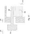
retention rod 1606 has been fully inserted within theinternal bore 1605, the retention tubes, includingretention tube 1604, are removed. Themattresses 1603 under compression expand slightly in the direction ofarrow 1701 but are still restrained within the stillage due to the presence of the retention rods, includingretention rod 1606. - After the removal of the retention tubes, the retention pins 1608 are located within their
respective rod holes 1609 to prevent movement of the retention rod in the direction ofarrow 1702. Furthermore, aretention head 1703 is provided at the opposite end of eachretention pin 1608 to prevent movement of theretention rod 1606 in the direction ofarrow 1704. - A top view of a secured stillage ready for transportation is illustrated in
Figure 18 . In this example, eightretention rods 1606 are in place, although the actual number may vary in order to achieve a required degree of retention while minimising the number of operations required to secure the stillage. - As previously described with reference to
Figure 17 , each retention rod is secured by aretention head 1703 at a first end and aretention pin 1609 at the opposition end. - When retained in a stillage of the type shown in
Figure 18 , the compressed mattresses may be transported and stored in thestorage buffer 106. If required, the mattresses could be stored for a considerable period of time although, operationally, the storage buffer is provided to even out seasonal variations and is not intended as a long-term storage solution. Furthermore, the stillages are configured to be used repeatedly and, in an embodiment, collapse to occupy a much smaller volume when being stored or transported prior to deployment.
Claims (15)
- An apparatus for compressing mattresses to reduce volume without causing permanent damage, in which each mattress includes a first support surface, a second support surface and a surrounding edge, characterised by:a compression device (1311, 1312); anda transportation frame (1401), wherein:said transportation frame is arranged to receive a mattress-stack of mattresses stacked with support surfaces in contact to a predetermined height; andsaid compression device is configured to apply additional mattresses, compress said additional mattresses in a direction substantially normal to said support surfaces to produce a compressed mattress stack and restrain said compressed mattress stack by restraining means.
- The apparatus of claim 1, wherein said compression device is configured to compress said compressed-mattress-stack to said predetermined height.
- The apparatus of claim 1 or claim 2, wherein said compression device is configured to repeatedly add non-compressed mattresses to said compressed-mattress-stack.
- The apparatus of any of claims 1 to 3, wherein said restraining means is supported by said transportation frame.
- The apparatus of any of claims 1 to 4, wherein said restraining means supports non-compressed mattresses.
- The apparatus of claim 5, wherein said restraining means has a bright finish to facilitate the movement of non-compressed mattresses.
- The apparatus of any of claims 4 to 6, wherein said restraining means is arranged to be retracted when said compression device is brought into contact with a first support surface.
- The apparatus of claim 7, wherein said restraining means is arranged to be re-introduced to restrain said compressed mattress stack after a compression cycle.
- The apparatus of any of claims 1 to 8, wherein said restraining means includes a plurality of restraining tubes.
- The apparatus of claim 9, wherein said transportation frame includes restraining holes for receiving said restraining tubes.
- The apparatus of claim 9 or claim 10, wherein said compression device includes restraining-channels for accommodating said restraining-tubes while maintaining said compressed-mattress-stack in compression.
- The apparatus of any of claims 9 to 11, wherein:said restraining tubes are temporary retraining means forming part of said compression device;each said restraining tube has a permanent restraining-rod inserted therein, in which each said restraining rod forms part of said transportation frame; andsaid compressed-mattress-stack is restrained by said restraining rods after the retraction of said restraining tubes.
- A method of compressing mattresses to reduce volume without causing permanent damage, characterised by the steps of:stacking a plurality of mattresses, with support surfaces being substantially in contact, to produce a mattress stack (201);applying pressure (501) substantially in the direction of said mattress stack, such that said pressure is normal to the support surfaces and consistent with pressure applied by a reclining body, thereby resulting in reversible compression to form a compressed mattress stack; andrestraining (601) said compressed mattress stack.
- The method of claim 13, wherein said restraining step includes the application of a temporary restraining device during a compression process.
- The method of claim 13 or claim 14, wherein:a first plurality of compressed mattresses is restrained by said temporary restraining device;a second plurality of non-compressed mattresses are placed upon said temporary restraining device;a compressing device is brought into contact with said non-compresses mattresses;said temporary restraining device is retracted;said compressing device deploys further compression to add said second-plurality of non-compressed mattresses to said first plurality of compresses mattresses;said temporary restraining device is deployed to restrain said compressed mattresses; andsaid compressing device is displaced away from said temporary restraining device.
Applications Claiming Priority (1)
| Application Number | Priority Date | Filing Date | Title |
|---|---|---|---|
| GB1813746.3A GB2577859B (en) | 2018-08-23 | 2018-08-23 | Compressing mattresses |
Publications (1)
| Publication Number | Publication Date |
|---|---|
| EP3613315A1 true EP3613315A1 (en) | 2020-02-26 |
Family
ID=63715263
Family Applications (1)
| Application Number | Title | Priority Date | Filing Date |
|---|---|---|---|
| EP19250009.8A Withdrawn EP3613315A1 (en) | 2018-08-23 | 2019-08-22 | Compressing mattresses to reduce volume without causing permanent damage |
Country Status (3)
| Country | Link |
|---|---|
| US (1) | US11180271B2 (en) |
| EP (1) | EP3613315A1 (en) |
| GB (1) | GB2577859B (en) |
Citations (3)
| Publication number | Priority date | Publication date | Assignee | Title |
|---|---|---|---|---|
| EP1120346A2 (en) * | 2000-01-11 | 2001-08-01 | Daniela Paparini | Device and procedure for packing a mattress filling |
| US7458193B2 (en) * | 2006-10-13 | 2008-12-02 | Primo International | Method and system for preparing mattresses for shipment |
| WO2011006229A1 (en) * | 2009-07-13 | 2011-01-20 | Primo International | Method and system for shipping mattresses |
Family Cites Families (13)
| Publication number | Priority date | Publication date | Assignee | Title |
|---|---|---|---|---|
| US1887226A (en) * | 1930-05-28 | 1932-11-08 | Moore Co | Baling press |
| US2309795A (en) * | 1940-05-14 | 1943-02-02 | Bertram L Siegel | Method and device for handling stacks of resilient articles |
| US2696164A (en) * | 1948-06-28 | 1954-12-07 | United Mattress Machinery Comp | Truck for handling spring assemblies |
| US2973090A (en) * | 1958-09-19 | 1961-02-28 | Charles M Dunlap | Reusable bedspring crate |
| US3797654A (en) * | 1972-01-10 | 1974-03-19 | Spiller Spring Co | Shipping containers |
| US3805354A (en) * | 1972-09-27 | 1974-04-23 | Guthrie Machinery Co | Apparatus for opening compressed packages |
| US3935690A (en) * | 1974-12-10 | 1976-02-03 | Lea James M | Method of packaging and unpackaging a self-inflating air mattress |
| DE2539289A1 (en) * | 1975-09-04 | 1977-04-07 | Recticel Deutsch Kunststoffe | PROCESS AND EQUIPMENT FOR PACKAGING BLOCKS MADE OF FOAMED PLASTIC (FOAM) |
| GB8613760D0 (en) * | 1986-06-06 | 1986-07-09 | Fiberglas Canada Inc | Packaging compressible items |
| US20090293431A1 (en) * | 2006-10-13 | 2009-12-03 | Primo International | Method and system for shipping mattresses |
| EP2423113A1 (en) * | 2010-08-30 | 2012-02-29 | Seelen A/S | Piling and compressing pieces of compressible material |
| US8342420B2 (en) * | 2010-10-27 | 2013-01-01 | Roberts Jr Richard W | Recyclable plastic structural articles and method of manufacture |
| EP3560843B1 (en) * | 2018-04-26 | 2020-11-18 | L&P Swiss Holding GmbH | Flat-packing machine for innerspring units |
-
2018
- 2018-08-23 GB GB1813746.3A patent/GB2577859B/en not_active Expired - Fee Related
-
2019
- 2019-08-22 EP EP19250009.8A patent/EP3613315A1/en not_active Withdrawn
- 2019-08-23 US US16/548,895 patent/US11180271B2/en not_active Expired - Fee Related
Patent Citations (3)
| Publication number | Priority date | Publication date | Assignee | Title |
|---|---|---|---|---|
| EP1120346A2 (en) * | 2000-01-11 | 2001-08-01 | Daniela Paparini | Device and procedure for packing a mattress filling |
| US7458193B2 (en) * | 2006-10-13 | 2008-12-02 | Primo International | Method and system for preparing mattresses for shipment |
| WO2011006229A1 (en) * | 2009-07-13 | 2011-01-20 | Primo International | Method and system for shipping mattresses |
Also Published As
| Publication number | Publication date |
|---|---|
| US20200062437A1 (en) | 2020-02-27 |
| GB2577859B (en) | 2023-04-05 |
| GB201813746D0 (en) | 2018-10-10 |
| GB2577859A (en) | 2020-04-15 |
| US11180271B2 (en) | 2021-11-23 |
Similar Documents
| Publication | Publication Date | Title |
|---|---|---|
| CN1789086B (en) | Device and process for packaging tyres | |
| CN105236162B (en) | A kind of pallet discharge apparatus | |
| KR100995483B1 (en) | Application of the loading register | |
| DE102014220046B4 (en) | Device for picking on pallets | |
| DE102009033687A1 (en) | Method and loading system for picking articles on target carriers | |
| CN109436484A (en) | A kind of cargo permutation palletizing system | |
| KR20190103262A (en) | Apparatus and method for handling bars | |
| EP2144830A2 (en) | Method and device for packing large drinks packs | |
| US11180271B2 (en) | Compressing mattresses to reduce volume without causing permanent damage | |
| DE202009009773U1 (en) | Loading system for picking items on destination load carriers | |
| US5700126A (en) | Spool feeding method and spool feeder | |
| CN1329250C (en) | A system and method for creation of load units | |
| CN109795394A (en) | Swing lift railway platform, swing lift system and handling method | |
| US7243479B2 (en) | Apparatus and method for loading a packaging station of an insulation batt packager | |
| EP3914516B1 (en) | Luggage loading system | |
| DE102011112896A1 (en) | Cargo transport system for transporting luggage between luggage feeding equipment of terminal building and cargo space of aircraft, includes transferring of cargo from feeding equipment transfer level to cargo storage plane | |
| EP0058670B1 (en) | Method and apparatus for packing goods | |
| CN116986099A (en) | Parallel indentation type flexible bag packaging machine | |
| US20090238656A1 (en) | Shipping chocks and methods for loading cylindrical-shaped objects for transport | |
| WO2022008010A1 (en) | Method for loading a container with vehicle tyres | |
| CN106163930A (en) | For the method not using tape to accommodate a bundle compressible material | |
| CN111874660A (en) | Vehicle loading device and method for loading a vehicle | |
| US4413400A (en) | Apparatus and process for nesting drum bodies | |
| EP3771666B1 (en) | Picking device and method | |
| DE2839412A1 (en) | METHOD AND DEVICE FOR STORING OR UNLOCKING CARRIER FRAMES |
Legal Events
| Date | Code | Title | Description |
|---|---|---|---|
| PUAI | Public reference made under article 153(3) epc to a published international application that has entered the european phase |
Free format text: ORIGINAL CODE: 0009012 |
|
| STAA | Information on the status of an ep patent application or granted ep patent |
Free format text: STATUS: THE APPLICATION HAS BEEN PUBLISHED |
|
| AK | Designated contracting states |
Kind code of ref document: A1 Designated state(s): AL AT BE BG CH CY CZ DE DK EE ES FI FR GB GR HR HU IE IS IT LI LT LU LV MC MK MT NL NO PL PT RO RS SE SI SK SM TR |
|
| AX | Request for extension of the european patent |
Extension state: BA ME |
|
| STAA | Information on the status of an ep patent application or granted ep patent |
Free format text: STATUS: THE APPLICATION IS DEEMED TO BE WITHDRAWN |
|
| 18D | Application deemed to be withdrawn |
Effective date: 20200827 |