EP3612674B1 - Garment care device with light indicators - Google Patents
Garment care device with light indicators Download PDFInfo
- Publication number
- EP3612674B1 EP3612674B1 EP18753437.5A EP18753437A EP3612674B1 EP 3612674 B1 EP3612674 B1 EP 3612674B1 EP 18753437 A EP18753437 A EP 18753437A EP 3612674 B1 EP3612674 B1 EP 3612674B1
- Authority
- EP
- European Patent Office
- Prior art keywords
- care device
- garment care
- light indicators
- light
- indicators
- Prior art date
- Legal status (The legal status is an assumption and is not a legal conclusion. Google has not performed a legal analysis and makes no representation as to the accuracy of the status listed.)
- Active
Links
- XEEYBQQBJWHFJM-UHFFFAOYSA-N Iron Chemical compound [Fe] XEEYBQQBJWHFJM-UHFFFAOYSA-N 0.000 claims description 30
- 238000006073 displacement reaction Methods 0.000 claims description 20
- 229910052742 iron Inorganic materials 0.000 claims description 15
- 238000000034 method Methods 0.000 claims description 9
- XLYOFNOQVPJJNP-UHFFFAOYSA-N water Substances O XLYOFNOQVPJJNP-UHFFFAOYSA-N 0.000 description 13
- 230000001133 acceleration Effects 0.000 description 8
- 230000000007 visual effect Effects 0.000 description 7
- 230000000694 effects Effects 0.000 description 5
- 230000007704 transition Effects 0.000 description 5
- 230000036961 partial effect Effects 0.000 description 3
- 238000013459 approach Methods 0.000 description 2
- 238000010409 ironing Methods 0.000 description 2
- 230000001681 protective effect Effects 0.000 description 2
- 230000003247 decreasing effect Effects 0.000 description 1
- 230000001419 dependent effect Effects 0.000 description 1
- 238000005485 electric heating Methods 0.000 description 1
- 239000004744 fabric Substances 0.000 description 1
- 239000012530 fluid Substances 0.000 description 1
- 230000003370 grooming effect Effects 0.000 description 1
- 230000000670 limiting effect Effects 0.000 description 1
- VIKNJXKGJWUCNN-XGXHKTLJSA-N norethisterone Chemical compound O=C1CC[C@@H]2[C@H]3CC[C@](C)([C@](CC4)(O)C#C)[C@@H]4[C@@H]3CCC2=C1 VIKNJXKGJWUCNN-XGXHKTLJSA-N 0.000 description 1
- 230000002250 progressing effect Effects 0.000 description 1
- 230000002829 reductive effect Effects 0.000 description 1
- 238000009692 water atomization Methods 0.000 description 1
Images



Classifications
-
- D—TEXTILES; PAPER
- D06—TREATMENT OF TEXTILES OR THE LIKE; LAUNDERING; FLEXIBLE MATERIALS NOT OTHERWISE PROVIDED FOR
- D06F—LAUNDERING, DRYING, IRONING, PRESSING OR FOLDING TEXTILE ARTICLES
- D06F75/00—Hand irons
-
- D—TEXTILES; PAPER
- D06—TREATMENT OF TEXTILES OR THE LIKE; LAUNDERING; FLEXIBLE MATERIALS NOT OTHERWISE PROVIDED FOR
- D06F—LAUNDERING, DRYING, IRONING, PRESSING OR FOLDING TEXTILE ARTICLES
- D06F75/00—Hand irons
- D06F75/08—Hand irons internally heated by electricity
- D06F75/10—Hand irons internally heated by electricity with means for supplying steam to the article being ironed
-
- D—TEXTILES; PAPER
- D06—TREATMENT OF TEXTILES OR THE LIKE; LAUNDERING; FLEXIBLE MATERIALS NOT OTHERWISE PROVIDED FOR
- D06F—LAUNDERING, DRYING, IRONING, PRESSING OR FOLDING TEXTILE ARTICLES
- D06F87/00—Apparatus for moistening or otherwise conditioning the article to be ironed or pressed
Definitions
- the invention relates to the field of garment care.
- Garment care devices with movement sensors are already known. However, those known devices do not provide any feedback to user on the movement information. This situation has negative consequences when the user would like to proactively modify the movement of the device in order to optimize the ironing settings, so that improved ironing results can be achieved.
- Document US 2013/125427 discloses an iron comprising: a water reservoir; a heatable soleplate; at least one water outlet opening; a water atomization and distribution unit; a sensor; and a control unit.
- Document US 2006/081588 discloses an interface for an iron with a graphic display indicating the current temperature selection, user controls for adjusting the current temperature selection, and a ready indicator.
- Document WO 82/03520 discloses an appliance including an audible alarm and visual indicator to warn the user of an impending power turn-off unless use of the appliance is detected by a use detector.
- Document US 6 104 009 discloses an electric clothes iron with circuitry for automatically disabling power to the iron when the iron is left unattended for a certain period of time.
- Document US 6 452 501 discloses an electric heating appliance adapted to signal the shut-off of a heater to a user by an indicator.
- the garment care device comprises:
- this solution gives to the user a visual feedback on the movement characteristics of the device.
- this visual feedback by the light indicators is informative on the movement characteristics.
- the visual feedback may indicate that the user is performing short strokes or long strokes.
- the visual feedback is also helpful for user to modify the way the device is moved. For example, if the switching of the light indicators is such that it reflects that the movement of the device characterizes short strokes, the user may decide to move the device with longer strokes, in particular if he knows that the device can enter a specific operating mode associated with long strokes.
- the invention also relates to a method of controlling at least one light indicator in a garment care device as mentioned above.
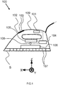
- Fig.1 depicts a first embodiment of a garment care device 100 according to the invention.
- the garment care device 100 comprises a sensor 101 connected to a control unit 104 for generating an output signal characterizing a movement of the garment care device.
- the garment care device also comprises a display 102 for displaying at least one light indicator 103.
- the control unit 104 is adapted to:
- the light indicators 103 correspond to surface-mounted light-emitting diodes ("LED").
- the light indicators correspond to discrete LEDs or a LED module.
- the senor 101 is an accelerometer of the type Micro Electro-Mechanical Systems (MEMS) which is adapted to generate at least one acceleration signal along any axis X, Y, Z forming an orthonormal reference, with Z corresponding to a vertical direction, and X-Y forming a horizontal plan.
- MEMS Micro Electro-Mechanical Systems
- the garment care device depicted in Fig. 1 comprises a water tank 105, a steam generator 106 receiving water from the reservoir 105.
- the steam generated in the steam generator 106 exits via steam vents 107 arranged in the soleplate S.
- a water pump 108 preferably controlled by control unit 104, is used to carry water from the water tank 105 to the steam generator 106.
- the senor 101 is arranged in a handle 109.
- an additional protective housing may provide additional protection to the sensor 101 (and/or control unit 102).
- Controlling the switching of the light indicators means any one of the following type of control:
- the brightness of a given light indicator is illustrated in Fig.2 and Fig.4 by a blacken surface (total or partial) of the corresponding light indicator.
- Fig.2 depicts a display 102 for displaying a plurality of light indicators in a garment care device according to Fig.1 .
- the light indicators have different sizes.
- the movement characteristics correspond to the amount of a linear displacement along a given direction (D) of the garment care device.
- the amount of a linear displacement may preferably correspond to the length of the user's stroke in this given direction (D) when using the garment care device.
- the given direction (D) correspond to the X axis.
- Fig.5A is an illustration of an example of a signal AS generated by a sensor 101 used in a garment care device according to the invention.
- the senor 101 is an accelerometer, and the output signal generated by the sensor 101 is an acceleration signal AS varying along the time in the given direction D, such as, for example, the X axis.
- the characteristics of the output signal correspond to the time interval d1 between two consecutive zero-crossing points of the output signal.
- the time interval d1 is compared to a given duration threshold d0:
- the given duration threshold d0 corresponds to the average value of the time interval between two consecutive zero-crossing points of the output signal corresponding to an average value of a user's stroke length.
- the stroke length along a given direction D corresponds to the linear distance of the garment care device between a starting position with zero speed, to the next position with zero speed.
- the average value of a stroke length of a user is the average linear distance that allows classifying a stroke length between a short stroke and a long stroke.
- a short stroke is smaller than the average linear distance
- a long stroke is larger than the average linear distance.
- the garment care device is preferably adapted to modify characteristics of some operating modes of the device, based on whether a short or long stroke is detected. For example the temperature of a soleplate can be varied, the temperature of a steam chamber can be varied, the amount of steam generated can be varied accordingly.
- the time interval d1 between two consecutive zero-crossing points of the output signal should be calculated with an offset corresponding to the estimated value of the noise level.
- An example is illustrated in Fig.5B .
- the given duration threshold d0 has a value in the range [200; 800] ms, preferably 550 ms.
- T he control unit 104 is adapted to control the switching of a number of light indicators, and the number of light indicators depends on the amount of linear displacement (i.e. distance).
- the number of light indicators which are switched to full brightness is smaller if the amount of linear displacement is below a given threshold, than the number of light indicator which are switched to full brightness if said amount of linear displacement is above said given threshold.
- the given threshold corresponds to the linear displacement value between a short stroke and a long stroke.
- the movement characteristics reflect that the garment care device is not moving.
- a no moving state of the garment care device can be detected by measuring the acceleration signal(s) along any one of axis X, Y, Z.
- the no moving state of the garment care device can be detected along one or a plurality of axis X, Y, Z. If a plurality of axis is considered, the acceleration signal must have a value lower that 50 mg along each of those axis in order to conclude that the garment care device is not moving.
- control unit 104 is adapted to switch at least one light indicator among said plurality of light indicators 103. This also applies to device depicted in Fig.3 .
- the movement characteristics reflect that the garment care device is moving.
- a moving state of the garment care device can be detected by measuring the acceleration signal(s) along any one of axis X, Y, Z.
- the control unit 104 is adapted to switch a number of light indicators 303 according to a given light pattern, wherein said given light pattern corresponds to a given number of said plurality of light indicators being switched.
- Other light patterns not forming part of the claimed invention correspond to a light brightness pattern; or a knight rider effect.
- the light indicator(s) may be switched on or off according to the detected movement of the device.
- the exact number of light indicators vary depending on the detected movement.
- the brightness of the light indicator(s) may be varied according to the detected movement of the device. In the example of a single light indicator, there may be multiple levels of brightness the indicator may occupy according to the detected movement of the device. Alternatively, in the case where there are multiple light indicators, the brightness of each indicator may be altered to a predefined pattern in response to a given detected motion.
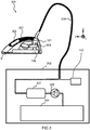
- Fig.3 depicts a second embodiment of a garment care device 300 according to the invention.
- This embodiment comprises an iron 301 cooperating with a base unit 302 via a hose cord 308.
- the base unit 302 comprises a water reservoir 304, a boiler 307 and a water pump 305 for providing water from the water reservoir 304 into the boiler 307.
- the boiler 307 generates steam as fluid in the hose cord 308. Steam which reaches the iron 301 is further heated in the steam generator 106.
- the control unit 104 is preferably arranged in the base unit 302, and communicate with the sensor 101 via a wire embedded inside the hose cord 308.
- the hose cord 308 is also adapted to carry power supply to the steam generator 106.
- the garment care device also comprises a display 302 for displaying a plurality of light indicators 303, which works similarly as the display 102 described above.
- a display 302 for displaying a plurality of light indicators 303, which works similarly as the display 102 described above.
- the number of light indicators is larger (i.e. five light indicators 303a, 303b, 303c, 303d, 303e).
- the display 302, the sensor 101 and the control unit 104 work similarly as in the embodiment of Fig.1 .
- the control unit 104 is adapted to switch the plurality of light indicators 303 according to a given light pattern.
- the light pattern is a knight rider effect.
- the knight rider effect is characterized by the fact that at any given time, one of the light indicators is fully bright and the neighbouring two light indicators have limited brightness, for example 30%. The rest of the light indicators are switched-off. The position of the fully bright light indicator on the display 302 is shifted overtime according to the sequence of display shown in Fig.4 : (b), (c), (d), (e), (f), (e), (d), (c), (b), etc...
- the knight rider effect is defined as a lighting sequence, wherein at a first stage in the lighting sequence a single light indicator of a plurality of light indicators is lit to full brightness, the light indicators adjacent the lit indicator are lit to limited brightness and the remaining indicators are turned off as shown in Figure 4(b) .
- the second stage of the lighting sequence one of the limited brightness indicators is lit to full brightness, the indicators adjacent this indicator are lit to a limited brightness and the remaining indicators are turned off as shown in Figure 4(c) .
- This transition gives the visual effect of the fully lit indicator having shifted to an adjacent indicator in a first direction as shown by the transition from Figure 4(b) to Figure 4(c) .
- the movement characteristics correspond to the speed of displacement (i.e. velocity) along a given direction (D) of the garment care device.
- the speed of displacement can be obtained by integrating the corresponding acceleration signal(s).
- control unit 104 is adapted to control the switching of a number of light indicators among said plurality of light indicators 103, 303, while having the number of light indicators depending on the speed of displacement.
- the number of light indicator which are switched is proportional to the speed of displacement. In other words, the higher the speed of device, the larger the number of light indicators which are switched.
- the garment care device corresponds to any one of the following types:
- Fig.6 depicts a flow chart of a method according to the invention of controlling a plurality of light indicators in a garment care device, such as a garment care device depicted along with Fig.1 and Fig.3 .
- the method comprises the steps of:
- the step of identifying 602 comprises:
- the step of identifying 602 comprises:
- control unit (104) may be adapted to:
- the given light pattern according to this example may correspond to either:
Landscapes
- Engineering & Computer Science (AREA)
- Textile Engineering (AREA)
- Professional, Industrial, Or Sporting Protective Garments (AREA)
Description
- The invention relates to the field of garment care.
- Garment care devices with movement sensors are already known. However, those known devices do not provide any feedback to user on the movement information. This situation has negative consequences when the user would like to proactively modify the movement of the device in order to optimize the ironing settings, so that improved ironing results can be achieved.
- Document
US 2004/133295 discloses a controller for a fabric grooming device to provide optimal user convenience, wherein the controller has at least an interface. - Document
US 2013/125427 discloses an iron comprising: a water reservoir; a heatable soleplate; at least one water outlet opening; a water atomization and distribution unit; a sensor; and a control unit. - Document
US 2010/242314 discloses a steam iron including a sensor for detecting and measuring movement of the steam iron. - Document
US 2006/081588 discloses an interface for an iron with a graphic display indicating the current temperature selection, user controls for adjusting the current temperature selection, and a ready indicator. - Document
WO 82/03520 - Document
US 6 104 009 discloses an electric clothes iron with circuitry for automatically disabling power to the iron when the iron is left unattended for a certain period of time. - Document
US 6 452 501 discloses an electric heating appliance adapted to signal the shut-off of a heater to a user by an indicator. - It is an object of the invention to propose an improved garment care device that avoids or mitigates above-mentioned problems.
- The invention is defined by the independent claims. The dependent claims define advantageous embodiments.
- To this end, the garment care device according to the invention comprises:
- a sensor connected to a control unit for generating an output signal characterizing a movement of the garment care device,
- a display for displaying a plurality of light indicators,
wherein the control unit is adapted to:- a) identify some movement characteristics in said output signal, said movement characteristics reflecting that the garment care device is moving, wherein said movement characteristics correspond to the amount of a linear displacement along a given direction of the garment care device,
- b) control the switching of said plurality of light indicators, based on the movement characteristics, and
- c) switch said plurality of light indicators (303) according to a given light pattern, and characterised in that the control unit is adapted to control the switching of a number of light indicators among said plurality of light indicators, said number of light indicators depending on said amount of linear displacement.
- This solution gives to the user a visual feedback on the movement characteristics of the device. First, this visual feedback by the light indicators is informative on the movement characteristics. For example, the visual feedback may indicate that the user is performing short strokes or long strokes. Secondly, the visual feedback is also helpful for user to modify the way the device is moved. For example, if the switching of the light indicators is such that it reflects that the movement of the device characterizes short strokes, the user may decide to move the device with longer strokes, in particular if he knows that the device can enter a specific operating mode associated with long strokes.
- The invention also relates to a method of controlling at least one light indicator in a garment care device as mentioned above.
- Detailed explanations and other aspects of the invention will be given below.
- Particular aspects of the invention will now be explained with reference to the embodiments described hereinafter and considered in connection with the accompanying drawings, in which identical parts or sub-steps are designated in the same manner :
-
Fig.1 depicts a first embodiment of a garment care device according to the invention, -
Fig.2 depicts a display for displaying at least one light indicator in a garment care device according toFig.1 , -
Fig.3 depicts a second embodiment of a garment care device according to the invention, -
Fig.4 depicts a display for displaying at least one light indicator in a garment care device according toFig.3 , -
Fig.5A-5B illustrate examples of a signals generated by an accelerometer used in a garment care device according to the invention, -
Fig.6 depicts a flow chart of a method according to the invention. -
Fig.1 depicts a first embodiment of agarment care device 100 according to the invention. - The
garment care device 100 comprises asensor 101 connected to acontrol unit 104 for generating an output signal characterizing a movement of the garment care device. - The garment care device also comprises a
display 102 for displaying at least onelight indicator 103. - The
control unit 104 is adapted to: - a) identify some movement characteristics in the output signal, said movement characteristics reflecting that the garment care device is moving,
- b) control the switching of said at least one
light indicator 103, based on said movement characteristics - c) switch said at least one light indicator (303) according to a given light pattern.
- This also applies to the device depicted in
Fig.3 . - For example, the
light indicators 103 correspond to surface-mounted light-emitting diodes ("LED"). Alternatively, the light indicators correspond to discrete LEDs or a LED module. - For example, the
sensor 101 is an accelerometer of the type Micro Electro-Mechanical Systems (MEMS) which is adapted to generate at least one acceleration signal along any axis X, Y, Z forming an orthonormal reference, with Z corresponding to a vertical direction, and X-Y forming a horizontal plan. - To generate steam, the garment care device depicted in
Fig. 1 comprises awater tank 105, asteam generator 106 receiving water from thereservoir 105. The steam generated in thesteam generator 106 exits viasteam vents 107 arranged in the soleplate S. In order to control the amount of steam generated, awater pump 108, preferably controlled bycontrol unit 104, is used to carry water from thewater tank 105 to thesteam generator 106. - Preferably, the
sensor 101 is arranged in ahandle 109. By doing so, the risk of damaging thesensor 101, for example as a result of water leaking from thereservoir 105, maybe reduced. Furthermore, an additional protective housing (not shown) may provide additional protection to the sensor 101 (and/or control unit 102). - Controlling the switching of the light indicators means any one of the following type of control:
- switching-on to full brightness,
- switching-off,
- increasing the light intensity by a certain percentage,
- decreasing the light intensity by a certain percentage.
- The brightness of a given light indicator is illustrated in
Fig.2 andFig.4 by a blacken surface (total or partial) of the corresponding light indicator. -
Fig.2 depicts adisplay 102 for displaying a plurality of light indicators in a garment care device according toFig.1 . - In this example, for sake of simplifying the explanation, only two light indicators are arranged, a first light indicator 103a, a
second light indicator 103b. However, a larger number of light indicators could be used similarly. - Preferably, the light indicators have different sizes.
- The movement characteristics correspond to the amount of a linear displacement along a given direction (D) of the garment care device.
- The amount of a linear displacement may preferably correspond to the length of the user's stroke in this given direction (D) when using the garment care device.
- For example, the given direction (D) correspond to the X axis.
-
Fig.5A is an illustration of an example of a signal AS generated by asensor 101 used in a garment care device according to the invention. - In the present case, the
sensor 101 is an accelerometer, and the output signal generated by thesensor 101 is an acceleration signal AS varying along the time in the given direction D, such as, for example, the X axis. The unit for the vertical axis of the graph is in milli g (or abbreviated as "mg"), with 1 g = 9.81 m/s2. - The characteristics of the output signal correspond to the time interval d1 between two consecutive zero-crossing points of the output signal. In order to classify the length of the user's stroke, the time interval d1 is compared to a given duration threshold d0:
- if the measured time interval d1 is smaller than the given duration threshold d0, the stroke of the user using the garment care device is considered as a short stroke.
- if the measured time interval d1 is larger than the given duration threshold d0, the stroke of the user using the garment care device is considered as a long stroke.
- The given duration threshold d0 corresponds to the average value of the time interval between two consecutive zero-crossing points of the output signal corresponding to an average value of a user's stroke length.
- By definition, the stroke length along a given direction D, corresponds to the linear distance of the garment care device between a starting position with zero speed, to the next position with zero speed.
- By definition, the average value of a stroke length of a user is the average linear distance that allows classifying a stroke length between a short stroke and a long stroke. A short stroke is smaller than the average linear distance, a long stroke is larger than the average linear distance.
- The garment care device is preferably adapted to modify characteristics of some operating modes of the device, based on whether a short or long stroke is detected. For example the temperature of a soleplate can be varied, the temperature of a steam chamber can be varied, the amount of steam generated can be varied accordingly.
- It is noted that in case the output signal generated by the
sensor 101 contains a certain level of noise, for example +/- 50 mg, the time interval d1 between two consecutive zero-crossing points of the output signal should be calculated with an offset corresponding to the estimated value of the noise level. An example is illustrated inFig.5B . - Preferably, the given duration threshold d0 has a value in the range [200; 800] ms, preferably 550 ms.
- The
control unit 104 is adapted to control the switching of a number of light indicators, and the number of light indicators depends on the amount of linear displacement (i.e. distance). - In particular, the number of light indicators which are switched to full brightness is smaller if the amount of linear displacement is below a given threshold, than the number of light indicator which are switched to full brightness if said amount of linear displacement is above said given threshold. The given threshold corresponds to the linear displacement value between a short stroke and a long stroke.
- For example:
- if short stroke is detected, one light indicator is switched-on.
- if long stroke is detected, two light indicators are switched-on.
- Alternatively:
- if short stroke is detected, one light indicator is switched to full brightness, and one light indicator is switched-on with partial brightness, as shown in the view (b) of
Fig.2 , - if long stroke is detected, two light indicators are switched to full brightness, as shown in the view (c) of
Fig.2 . - Preferably, the movement characteristics reflect that the garment care device is not moving.
- For example, a no moving state of the garment care device can be detected by measuring the acceleration signal(s) along any one of axis X, Y, Z. In particular, if along a given axis, the acceleration signal has a value lower than 50 mg (or more generally the noise level), with 1 g = 9.81 m/s2, it can be considered that the device is not moving along this given axis.
- The no moving state of the garment care device can be detected along one or a plurality of axis X, Y, Z. If a plurality of axis is considered, the acceleration signal must have a value lower that 50 mg along each of those axis in order to conclude that the garment care device is not moving.
- Preferably, if a no moving state of the garment care device is detected, the
control unit 104 is adapted to switch at least one light indicator among said plurality oflight indicators 103. This also applies to device depicted inFig.3 . - For example, if a no moving state of the garment care device is detected:
- only one light indicator, for example light indicator 103a, is switched with a brightness less than the full brightness, as illustrated in view (a) of
Fig.2 , or - all light indicators are switched with a full brightness as illustrated in view (c) of
Fig.2 . - According to the invention, the movement characteristics reflect that the garment care device is moving.
- For example, a moving state of the garment care device can be detected by measuring the acceleration signal(s) along any one of axis X, Y, Z. In particular, if along a given axis, the acceleration signal has a value larger than 50 mg (or more generally the noise level), with 1 g = 9.81 m/s2, it can be considered that the device is moving along this given axis, so overall moving.
- According to the invention, if a moving state of the garment care device is detected, the
control unit 104 is adapted to switch a number oflight indicators 303 according to a given light pattern, wherein said given light pattern corresponds to a given number of said plurality of light indicators being switched. Other light patterns not forming part of the claimed invention correspond to a light brightness pattern; or a knight rider effect. - In the case where the light pattern corresponds to a given number of said plurality of light indicators being switched, the light indicator(s) may be switched on or off according to the detected movement of the device. The exact number of light indicators vary depending on the detected movement.
- In the example where the light pattern is light brightness pattern, the brightness of the light indicator(s) may be varied according to the detected movement of the device. In the example of a single light indicator, there may be multiple levels of brightness the indicator may occupy according to the detected movement of the device. Alternatively, in the case where there are multiple light indicators, the brightness of each indicator may be altered to a predefined pattern in response to a given detected motion.
-
Fig.3 depicts a second embodiment of agarment care device 300 according to the invention. This embodiment comprises aniron 301 cooperating with abase unit 302 via ahose cord 308. Thebase unit 302 comprises awater reservoir 304, aboiler 307 and awater pump 305 for providing water from thewater reservoir 304 into theboiler 307. Theboiler 307 generates steam as fluid in thehose cord 308. Steam which reaches theiron 301 is further heated in thesteam generator 106. Thecontrol unit 104 is preferably arranged in thebase unit 302, and communicate with thesensor 101 via a wire embedded inside thehose cord 308. Thehose cord 308 is also adapted to carry power supply to thesteam generator 106. - The garment care device also comprises a
display 302 for displaying a plurality oflight indicators 303, which works similarly as thedisplay 102 described above. One difference is that the number of light indicators is larger (i.e. fivelight indicators display 302, thesensor 101 and thecontrol unit 104 work similarly as in the embodiment ofFig.1 . - According to the invention, if a moving state of the
garment care device 300 is detected, in particular a moving state of theiron 301, thecontrol unit 104 is adapted to switch the plurality oflight indicators 303 according to a given light pattern. - According to an example not forming part of the claimed invention, the light pattern is a knight rider effect. The knight rider effect is characterized by the fact that at any given time, one of the light indicators is fully bright and the neighbouring two light indicators have limited brightness, for example 30%. The rest of the light indicators are switched-off. The position of the fully bright light indicator on the
display 302 is shifted overtime according to the sequence of display shown inFig.4 : (b), (c), (d), (e), (f), (e), (d), (c), (b), etc... - In other words, the knight rider effect is defined as a lighting sequence, wherein at a first stage in the lighting sequence a single light indicator of a plurality of light indicators is lit to full brightness, the light indicators adjacent the lit indicator are lit to limited brightness and the remaining indicators are turned off as shown in
Figure 4(b) . In the second stage of the lighting sequence, one of the limited brightness indicators is lit to full brightness, the indicators adjacent this indicator are lit to a limited brightness and the remaining indicators are turned off as shown inFigure 4(c) . This transition gives the visual effect of the fully lit indicator having shifted to an adjacent indicator in a first direction as shown by the transition fromFigure 4(b) to Figure 4(c) . This transition is sequentially repeated until the fully lit indicator is the last indicator in the first direction, i.e. there are no further adjacent light indicators in said first direction as shown inFigure 4(f) . At this point, the direction of progression is reversed and the fully lit indicator progresses in a sequential manner along a second direction, opposite to the first direction as shown in the transition fromFigure 4(f) to Figure 4(e) . The transition described above is performed in the second direction until the fully lit indicator is the last indicator in the second direction. This above described lighting sequence may then be repeated, alternating between the first and second directions. Thus, the knight rider effect provides the visual effect of a fully lit light indicator progressing back and forth in a stepwise manner across a plurality of light indicators. - According to an example not forming part of the claimed invention, the movement characteristics correspond to the speed of displacement (i.e. velocity) along a given direction (D) of the garment care device. For example, this applies to devices depicted in
Fig.1 andFig.3 . For example, the speed of displacement can be obtained by integrating the corresponding acceleration signal(s). - Preferably, according to this example the
control unit 104 is adapted to control the switching of a number of light indicators among said plurality oflight indicators - For example, the number of light indicator which are switched (with full or partial brightness), is proportional to the speed of displacement. In other words, the higher the speed of device, the larger the number of light indicators which are switched.
- Preferably, the garment care device corresponds to any one of the following types:
- dry iron,
- steam iron, as depicted in
Fig.1 , - pressurized steam generator (with base connected to an iron via a hose cord, either the hose carrying water, either the hose cord carrying steam as depicted in
Fig.3 ), - handheld garment steamer,
- stand garment steamer.
-
Fig.6 depicts a flow chart of a method according to the invention of controlling a plurality of light indicators in a garment care device, such as a garment care device depicted along withFig.1 andFig.3 . The method comprises the steps of: - generating 601 an output signal characterizing a movement of said garment care device,
- identifying 602 some movement characteristics in said output signal,
- control 603 the switching of said at least one light indicator, based on said movement characteristics.
- According to the claimed invention, the step of identifying 602 comprises:
- identifying the amount of a linear displacement along a given direction (D) of the garment care device.
- According to examples not forming part of the claimed invention, the step of identifying 602 comprises:
- identifying that the garment care device is not moving, or
- identifying that the garment care device is moving, or
- identifying the speed of displacement along a given direction (D) of the garment care device.
- In a further example, the control unit (104) may be adapted to:
- a) identify some movement characteristics in said output signal, said movement characteristics reflecting that the garment care device is not moving, and
- b) control the switching of at least one light indicator (103, 303) according to a given light pattern.
- The given light pattern according to this example may correspond to either:
- a given number of said at least one light indicator being switched, or
- a light brightness pattern.
- The above embodiments as described are only illustrative, and not intended to limit the technique approaches of the present invention. Although the present invention is described in details referring to the preferable embodiments, those skilled in the art will understand that the technique approaches of the present invention can be modified or equally displaced without departing from the protective scope of the claims of the present invention. In the claims, the word "comprising" does not exclude other elements or steps, and the indefinite article "a" or "an" does not exclude a plurality. Any reference signs in the claims should not be construed as limiting the scope.
Claims (5)
- A garment care device (100) comprising:- a sensor (101) connected to a control unit (104) for generating an output signal characterizing a movement of said garment care device,- a display (102, 302) for displaying a plurality of light indicators (103, 303), wherein the control unit (104) is adapted to:a) identify some movement characteristics in said output signal, said movement characteristics reflecting that the garment care device is moving, wherein said movement characteristics correspond to the amount of a linear displacement along a given direction (D) of the garment care device,b) control the switching of said plurality of light indicators (103, 303), based on said movement characteristics, andc) switch said plurality of light indicators (303) according to a given light pattern,and characterised in that the control unit (104) is adapted to control the switching of a number of light indicators among said plurality of light indicators (103, 303), said number of light indicators depending on said amount of linear displacement.
- A garment care device as claimed in claim 1, wherein the number of light indicators which are switched to full brightness is smaller if said amount of linear displacement is below a given threshold, than the number of light indicators which are switched to full brightness if said amount of linear displacement is above said given threshold.
- A garment care device as claimed in any of claims 1 to 2, wherein said sensor (101) is an accelerometer of the type Micro Electro-Mechanical Systems (MEMS).
- A garment care device as claimed in any of claims 1 to 3, corresponding to any of the types defined by dry iron, steam iron, pressurized steam generator, handheld steamer, stand garment steamer.
- Method of controlling plurality of light indicators in a garment care device, the method comprising the steps of:- generating (601) an output signal characterizing a movement of said garment care device,- identifying (602) some movement characteristics in said output signal, wherein said movement characteristics correspond to the amount of a linear displacement along a given direction (D) of the garment care device,- controlling (603) the switching of said plurality of light indicators, based on said movement characteristics- and characterised in that the method further includes controlling the switching of a number of light indicators among said plurality of light indicators, said number of light indicator depending on said amount of linear displacement.
Applications Claiming Priority (2)
| Application Number | Priority Date | Filing Date | Title |
|---|---|---|---|
| EP17187952.1A EP3447185A1 (en) | 2017-08-25 | 2017-08-25 | Garment care device with light indicators |
| PCT/EP2018/072562 WO2019038284A1 (en) | 2017-08-25 | 2018-08-21 | Garment care device with light indicators |
Publications (2)
| Publication Number | Publication Date |
|---|---|
| EP3612674A1 EP3612674A1 (en) | 2020-02-26 |
| EP3612674B1 true EP3612674B1 (en) | 2020-10-07 |
Family
ID=59713889
Family Applications (2)
| Application Number | Title | Priority Date | Filing Date |
|---|---|---|---|
| EP17187952.1A Withdrawn EP3447185A1 (en) | 2017-08-25 | 2017-08-25 | Garment care device with light indicators |
| EP18753437.5A Active EP3612674B1 (en) | 2017-08-25 | 2018-08-21 | Garment care device with light indicators |
Family Applications Before (1)
| Application Number | Title | Priority Date | Filing Date |
|---|---|---|---|
| EP17187952.1A Withdrawn EP3447185A1 (en) | 2017-08-25 | 2017-08-25 | Garment care device with light indicators |
Country Status (4)
| Country | Link |
|---|---|
| EP (2) | EP3447185A1 (en) |
| CN (1) | CN111295474B (en) |
| RU (1) | RU2728751C1 (en) |
| WO (1) | WO2019038284A1 (en) |
Cited By (1)
| Publication number | Priority date | Publication date | Assignee | Title |
|---|---|---|---|---|
| FR3115050A1 (en) * | 2020-10-13 | 2022-04-15 | Seb S.A. | IRON INCLUDING A LIGHTING DEVICE |
Family Cites Families (13)
| Publication number | Priority date | Publication date | Assignee | Title |
|---|---|---|---|---|
| WO1982003520A1 (en) * | 1981-04-07 | 1982-10-14 | Robert C Franklin | Appliance non-use detection safety power shut-off system |
| IT1240471B (en) * | 1990-06-01 | 1993-12-17 | Nida S.R.L. | STEAM IRON, PERFECTED. |
| JP3068177B2 (en) * | 1990-11-30 | 2000-07-24 | 東芝ホームテクノ株式会社 | Electric iron |
| WO1996034510A2 (en) * | 1995-04-25 | 1996-10-31 | Philips Electronics N.V. | Safety device for an electric heating appliance |
| US6104009A (en) * | 1998-12-07 | 2000-08-15 | Hp Intellectual Corp. | Electrical appliance having user proximity sensor |
| US6665963B1 (en) * | 2002-07-29 | 2003-12-23 | Jean M. Wright | Clothing iron with detachable light assembly |
| US20040133295A1 (en) * | 2002-09-30 | 2004-07-08 | Conair Corporation | Controller and method for a fabric grooming device |
| US20060081588A1 (en) * | 2004-10-05 | 2006-04-20 | Bowser John O | Electric pressing iron with user interface |
| US8091257B2 (en) * | 2009-03-31 | 2012-01-10 | Freescale Semiconductor, Inc. | Steam iron with acceleration and tilt detection |
| EP2418317A1 (en) * | 2010-08-12 | 2012-02-15 | Koninklijke Philips Electronics N.V. | Iron featuring liquid phase garment moisturization via soleplate |
| CN202466247U (en) * | 2012-02-24 | 2012-10-03 | 厦门大学 | Electric iron |
| CN104074040B (en) * | 2014-06-27 | 2016-08-24 | 微动科技(杭州)有限公司 | It is applied to intelligence system and the processing method of electric iron |
| CN104287327A (en) * | 2014-10-09 | 2015-01-21 | 广东小天才科技有限公司 | Method and device for reflecting motion state of motion bracelet |
-
2017
- 2017-08-25 EP EP17187952.1A patent/EP3447185A1/en not_active Withdrawn
-
2018
- 2018-08-21 WO PCT/EP2018/072562 patent/WO2019038284A1/en not_active Ceased
- 2018-08-21 CN CN201880037480.5A patent/CN111295474B/en active Active
- 2018-08-21 RU RU2019138232A patent/RU2728751C1/en active
- 2018-08-21 EP EP18753437.5A patent/EP3612674B1/en active Active
Non-Patent Citations (1)
| Title |
|---|
| None * |
Cited By (2)
| Publication number | Priority date | Publication date | Assignee | Title |
|---|---|---|---|---|
| FR3115050A1 (en) * | 2020-10-13 | 2022-04-15 | Seb S.A. | IRON INCLUDING A LIGHTING DEVICE |
| EP3985165A1 (en) * | 2020-10-13 | 2022-04-20 | Seb S.A. | Iron comprising a lighting device |
Also Published As
| Publication number | Publication date |
|---|---|
| WO2019038284A1 (en) | 2019-02-28 |
| EP3612674A1 (en) | 2020-02-26 |
| CN111295474B (en) | 2021-06-18 |
| CN111295474A (en) | 2020-06-16 |
| RU2728751C1 (en) | 2020-07-30 |
| EP3447185A1 (en) | 2019-02-27 |
Similar Documents
| Publication | Publication Date | Title |
|---|---|---|
| US9055644B2 (en) | Lighting apparatus | |
| CN101292575B (en) | Lighting system with changeable effect | |
| US20210267024A1 (en) | Cooking apparatus and control method thereof | |
| JPWO2014064941A1 (en) | Induction heating device | |
| EP3612674A1 (en) | Garment care device with light indicators | |
| CN203115559U (en) | Light indicating device for household appliances | |
| EP1646828B1 (en) | Electric oven and method for controlling such an oven | |
| US20060081588A1 (en) | Electric pressing iron with user interface | |
| KR20130012424A (en) | Hair iron | |
| KR101657515B1 (en) | Electric range with power that is able to detect control | |
| KR20110002909A (en) | Water light emitting device | |
| JP2007031942A (en) | Toilet equipment | |
| JP6667096B2 (en) | Signal indicator | |
| CN105182806A (en) | Electrical Appliance Switch And Method For Controlling Electrical Appliance | |
| KR20040065959A (en) | Light emitting apparatus in tap water responding to water temperature | |
| KR20110051357A (en) | Cooker and Control Method | |
| KR20120117706A (en) | Safe controller | |
| KR100878134B1 (en) | Electronic control valve system with status display function and control method thereof | |
| US20080094238A1 (en) | Power Controller With Audio Feedback | |
| KR101086173B1 (en) | Steam cooking equipment and control method | |
| KR200467398Y1 (en) | An electric fan speed controller using CYCLE variableness | |
| KR100926674B1 (en) | Digital Thermostat for Detecting Fault | |
| KR100747432B1 (en) | How to control your steam cleaner | |
| JP2005019178A (en) | Induction heating cooker | |
| AU2004255018B2 (en) | Controlling apparatus of an electric oven and controlling method of the same |
Legal Events
| Date | Code | Title | Description |
|---|---|---|---|
| STAA | Information on the status of an ep patent application or granted ep patent |
Free format text: STATUS: UNKNOWN |
|
| STAA | Information on the status of an ep patent application or granted ep patent |
Free format text: STATUS: THE INTERNATIONAL PUBLICATION HAS BEEN MADE |
|
| PUAI | Public reference made under article 153(3) epc to a published international application that has entered the european phase |
Free format text: ORIGINAL CODE: 0009012 |
|
| STAA | Information on the status of an ep patent application or granted ep patent |
Free format text: STATUS: REQUEST FOR EXAMINATION WAS MADE |
|
| 17P | Request for examination filed |
Effective date: 20191121 |
|
| AK | Designated contracting states |
Kind code of ref document: A1 Designated state(s): AL AT BE BG CH CY CZ DE DK EE ES FI FR GB GR HR HU IE IS IT LI LT LU LV MC MK MT NL NO PL PT RO RS SE SI SK SM TR |
|
| AX | Request for extension of the european patent |
Extension state: BA ME |
|
| RAP1 | Party data changed (applicant data changed or rights of an application transferred) |
Owner name: KONINKLIJKE PHILIPS N.V. |
|
| GRAP | Despatch of communication of intention to grant a patent |
Free format text: ORIGINAL CODE: EPIDOSNIGR1 |
|
| STAA | Information on the status of an ep patent application or granted ep patent |
Free format text: STATUS: GRANT OF PATENT IS INTENDED |
|
| INTG | Intention to grant announced |
Effective date: 20200331 |
|
| GRAS | Grant fee paid |
Free format text: ORIGINAL CODE: EPIDOSNIGR3 |
|
| GRAA | (expected) grant |
Free format text: ORIGINAL CODE: 0009210 |
|
| STAA | Information on the status of an ep patent application or granted ep patent |
Free format text: STATUS: THE PATENT HAS BEEN GRANTED |
|
| DAV | Request for validation of the european patent (deleted) | ||
| DAX | Request for extension of the european patent (deleted) | ||
| AK | Designated contracting states |
Kind code of ref document: B1 Designated state(s): AL AT BE BG CH CY CZ DE DK EE ES FI FR GB GR HR HU IE IS IT LI LT LU LV MC MK MT NL NO PL PT RO RS SE SI SK SM TR |
|
| REG | Reference to a national code |
Ref country code: GB Ref legal event code: FG4D |
|
| REG | Reference to a national code |
Ref country code: CH Ref legal event code: EP Ref country code: AT Ref legal event code: REF Ref document number: 1321258 Country of ref document: AT Kind code of ref document: T Effective date: 20201015 |
|
| REG | Reference to a national code |
Ref country code: IE Ref legal event code: FG4D |
|
| REG | Reference to a national code |
Ref country code: DE Ref legal event code: R096 Ref document number: 602018008558 Country of ref document: DE |
|
| REG | Reference to a national code |
Ref country code: NL Ref legal event code: MP Effective date: 20201007 |
|
| REG | Reference to a national code |
Ref country code: AT Ref legal event code: MK05 Ref document number: 1321258 Country of ref document: AT Kind code of ref document: T Effective date: 20201007 |
|
| PG25 | Lapsed in a contracting state [announced via postgrant information from national office to epo] |
Ref country code: FI Free format text: LAPSE BECAUSE OF FAILURE TO SUBMIT A TRANSLATION OF THE DESCRIPTION OR TO PAY THE FEE WITHIN THE PRESCRIBED TIME-LIMIT Effective date: 20201007 Ref country code: PT Free format text: LAPSE BECAUSE OF FAILURE TO SUBMIT A TRANSLATION OF THE DESCRIPTION OR TO PAY THE FEE WITHIN THE PRESCRIBED TIME-LIMIT Effective date: 20210208 Ref country code: RS Free format text: LAPSE BECAUSE OF FAILURE TO SUBMIT A TRANSLATION OF THE DESCRIPTION OR TO PAY THE FEE WITHIN THE PRESCRIBED TIME-LIMIT Effective date: 20201007 Ref country code: NO Free format text: LAPSE BECAUSE OF FAILURE TO SUBMIT A TRANSLATION OF THE DESCRIPTION OR TO PAY THE FEE WITHIN THE PRESCRIBED TIME-LIMIT Effective date: 20210107 Ref country code: GR Free format text: LAPSE BECAUSE OF FAILURE TO SUBMIT A TRANSLATION OF THE DESCRIPTION OR TO PAY THE FEE WITHIN THE PRESCRIBED TIME-LIMIT Effective date: 20210108 |
|
| REG | Reference to a national code |
Ref country code: LT Ref legal event code: MG4D |
|
| PG25 | Lapsed in a contracting state [announced via postgrant information from national office to epo] |
Ref country code: AT Free format text: LAPSE BECAUSE OF FAILURE TO SUBMIT A TRANSLATION OF THE DESCRIPTION OR TO PAY THE FEE WITHIN THE PRESCRIBED TIME-LIMIT Effective date: 20201007 Ref country code: ES Free format text: LAPSE BECAUSE OF FAILURE TO SUBMIT A TRANSLATION OF THE DESCRIPTION OR TO PAY THE FEE WITHIN THE PRESCRIBED TIME-LIMIT Effective date: 20201007 Ref country code: SE Free format text: LAPSE BECAUSE OF FAILURE TO SUBMIT A TRANSLATION OF THE DESCRIPTION OR TO PAY THE FEE WITHIN THE PRESCRIBED TIME-LIMIT Effective date: 20201007 Ref country code: LV Free format text: LAPSE BECAUSE OF FAILURE TO SUBMIT A TRANSLATION OF THE DESCRIPTION OR TO PAY THE FEE WITHIN THE PRESCRIBED TIME-LIMIT Effective date: 20201007 Ref country code: PL Free format text: LAPSE BECAUSE OF FAILURE TO SUBMIT A TRANSLATION OF THE DESCRIPTION OR TO PAY THE FEE WITHIN THE PRESCRIBED TIME-LIMIT Effective date: 20201007 Ref country code: IS Free format text: LAPSE BECAUSE OF FAILURE TO SUBMIT A TRANSLATION OF THE DESCRIPTION OR TO PAY THE FEE WITHIN THE PRESCRIBED TIME-LIMIT Effective date: 20210207 Ref country code: BG Free format text: LAPSE BECAUSE OF FAILURE TO SUBMIT A TRANSLATION OF THE DESCRIPTION OR TO PAY THE FEE WITHIN THE PRESCRIBED TIME-LIMIT Effective date: 20210107 |
|
| PG25 | Lapsed in a contracting state [announced via postgrant information from national office to epo] |
Ref country code: HR Free format text: LAPSE BECAUSE OF FAILURE TO SUBMIT A TRANSLATION OF THE DESCRIPTION OR TO PAY THE FEE WITHIN THE PRESCRIBED TIME-LIMIT Effective date: 20201007 Ref country code: NL Free format text: LAPSE BECAUSE OF FAILURE TO SUBMIT A TRANSLATION OF THE DESCRIPTION OR TO PAY THE FEE WITHIN THE PRESCRIBED TIME-LIMIT Effective date: 20201007 |
|
| REG | Reference to a national code |
Ref country code: DE Ref legal event code: R097 Ref document number: 602018008558 Country of ref document: DE |
|
| PG25 | Lapsed in a contracting state [announced via postgrant information from national office to epo] |
Ref country code: EE Free format text: LAPSE BECAUSE OF FAILURE TO SUBMIT A TRANSLATION OF THE DESCRIPTION OR TO PAY THE FEE WITHIN THE PRESCRIBED TIME-LIMIT Effective date: 20201007 Ref country code: CZ Free format text: LAPSE BECAUSE OF FAILURE TO SUBMIT A TRANSLATION OF THE DESCRIPTION OR TO PAY THE FEE WITHIN THE PRESCRIBED TIME-LIMIT Effective date: 20201007 Ref country code: SM Free format text: LAPSE BECAUSE OF FAILURE TO SUBMIT A TRANSLATION OF THE DESCRIPTION OR TO PAY THE FEE WITHIN THE PRESCRIBED TIME-LIMIT Effective date: 20201007 Ref country code: SK Free format text: LAPSE BECAUSE OF FAILURE TO SUBMIT A TRANSLATION OF THE DESCRIPTION OR TO PAY THE FEE WITHIN THE PRESCRIBED TIME-LIMIT Effective date: 20201007 Ref country code: LT Free format text: LAPSE BECAUSE OF FAILURE TO SUBMIT A TRANSLATION OF THE DESCRIPTION OR TO PAY THE FEE WITHIN THE PRESCRIBED TIME-LIMIT Effective date: 20201007 Ref country code: RO Free format text: LAPSE BECAUSE OF FAILURE TO SUBMIT A TRANSLATION OF THE DESCRIPTION OR TO PAY THE FEE WITHIN THE PRESCRIBED TIME-LIMIT Effective date: 20201007 |
|
| PLBE | No opposition filed within time limit |
Free format text: ORIGINAL CODE: 0009261 |
|
| STAA | Information on the status of an ep patent application or granted ep patent |
Free format text: STATUS: NO OPPOSITION FILED WITHIN TIME LIMIT |
|
| PG25 | Lapsed in a contracting state [announced via postgrant information from national office to epo] |
Ref country code: DK Free format text: LAPSE BECAUSE OF FAILURE TO SUBMIT A TRANSLATION OF THE DESCRIPTION OR TO PAY THE FEE WITHIN THE PRESCRIBED TIME-LIMIT Effective date: 20201007 |
|
| 26N | No opposition filed |
Effective date: 20210708 |
|
| PG25 | Lapsed in a contracting state [announced via postgrant information from national office to epo] |
Ref country code: AL Free format text: LAPSE BECAUSE OF FAILURE TO SUBMIT A TRANSLATION OF THE DESCRIPTION OR TO PAY THE FEE WITHIN THE PRESCRIBED TIME-LIMIT Effective date: 20201007 |
|
| PG25 | Lapsed in a contracting state [announced via postgrant information from national office to epo] |
Ref country code: SI Free format text: LAPSE BECAUSE OF FAILURE TO SUBMIT A TRANSLATION OF THE DESCRIPTION OR TO PAY THE FEE WITHIN THE PRESCRIBED TIME-LIMIT Effective date: 20201007 |
|
| REG | Reference to a national code |
Ref country code: CH Ref legal event code: PL |
|
| PG25 | Lapsed in a contracting state [announced via postgrant information from national office to epo] |
Ref country code: MC Free format text: LAPSE BECAUSE OF FAILURE TO SUBMIT A TRANSLATION OF THE DESCRIPTION OR TO PAY THE FEE WITHIN THE PRESCRIBED TIME-LIMIT Effective date: 20201007 |
|
| REG | Reference to a national code |
Ref country code: BE Ref legal event code: MM Effective date: 20210831 |
|
| PG25 | Lapsed in a contracting state [announced via postgrant information from national office to epo] |
Ref country code: LI Free format text: LAPSE BECAUSE OF NON-PAYMENT OF DUE FEES Effective date: 20210831 Ref country code: CH Free format text: LAPSE BECAUSE OF NON-PAYMENT OF DUE FEES Effective date: 20210831 |
|
| PG25 | Lapsed in a contracting state [announced via postgrant information from national office to epo] |
Ref country code: IS Free format text: LAPSE BECAUSE OF FAILURE TO SUBMIT A TRANSLATION OF THE DESCRIPTION OR TO PAY THE FEE WITHIN THE PRESCRIBED TIME-LIMIT Effective date: 20210207 Ref country code: LU Free format text: LAPSE BECAUSE OF NON-PAYMENT OF DUE FEES Effective date: 20210821 |
|
| PG25 | Lapsed in a contracting state [announced via postgrant information from national office to epo] |
Ref country code: IE Free format text: LAPSE BECAUSE OF NON-PAYMENT OF DUE FEES Effective date: 20210821 Ref country code: BE Free format text: LAPSE BECAUSE OF NON-PAYMENT OF DUE FEES Effective date: 20210831 |
|
| PGFP | Annual fee paid to national office [announced via postgrant information from national office to epo] |
Ref country code: TR Payment date: 20220809 Year of fee payment: 5 Ref country code: IT Payment date: 20220819 Year of fee payment: 5 Ref country code: GB Payment date: 20220823 Year of fee payment: 5 Ref country code: DE Payment date: 20220826 Year of fee payment: 5 |
|
| PGFP | Annual fee paid to national office [announced via postgrant information from national office to epo] |
Ref country code: FR Payment date: 20220824 Year of fee payment: 5 |
|
| PG25 | Lapsed in a contracting state [announced via postgrant information from national office to epo] |
Ref country code: CY Free format text: LAPSE BECAUSE OF FAILURE TO SUBMIT A TRANSLATION OF THE DESCRIPTION OR TO PAY THE FEE WITHIN THE PRESCRIBED TIME-LIMIT Effective date: 20201007 |
|
| P01 | Opt-out of the competence of the unified patent court (upc) registered |
Effective date: 20230530 |
|
| PG25 | Lapsed in a contracting state [announced via postgrant information from national office to epo] |
Ref country code: HU Free format text: LAPSE BECAUSE OF FAILURE TO SUBMIT A TRANSLATION OF THE DESCRIPTION OR TO PAY THE FEE WITHIN THE PRESCRIBED TIME-LIMIT; INVALID AB INITIO Effective date: 20180821 |
|
| REG | Reference to a national code |
Ref country code: GB Ref legal event code: 732E Free format text: REGISTERED BETWEEN 20231214 AND 20231220 |
|
| REG | Reference to a national code |
Ref country code: DE Ref legal event code: R119 Ref document number: 602018008558 Country of ref document: DE |
|
| GBPC | Gb: european patent ceased through non-payment of renewal fee |
Effective date: 20230821 |
|
| PG25 | Lapsed in a contracting state [announced via postgrant information from national office to epo] |
Ref country code: MK Free format text: LAPSE BECAUSE OF FAILURE TO SUBMIT A TRANSLATION OF THE DESCRIPTION OR TO PAY THE FEE WITHIN THE PRESCRIBED TIME-LIMIT Effective date: 20201007 |
|
| PG25 | Lapsed in a contracting state [announced via postgrant information from national office to epo] |
Ref country code: GB Free format text: LAPSE BECAUSE OF NON-PAYMENT OF DUE FEES Effective date: 20230821 |
|
| PG25 | Lapsed in a contracting state [announced via postgrant information from national office to epo] |
Ref country code: IT Free format text: LAPSE BECAUSE OF NON-PAYMENT OF DUE FEES Effective date: 20230821 Ref country code: GB Free format text: LAPSE BECAUSE OF NON-PAYMENT OF DUE FEES Effective date: 20230821 Ref country code: FR Free format text: LAPSE BECAUSE OF NON-PAYMENT OF DUE FEES Effective date: 20230831 Ref country code: DE Free format text: LAPSE BECAUSE OF NON-PAYMENT OF DUE FEES Effective date: 20240301 |
|
| PG25 | Lapsed in a contracting state [announced via postgrant information from national office to epo] |
Ref country code: MT Free format text: LAPSE BECAUSE OF FAILURE TO SUBMIT A TRANSLATION OF THE DESCRIPTION OR TO PAY THE FEE WITHIN THE PRESCRIBED TIME-LIMIT Effective date: 20201007 |