EP3612434B1 - Method and control arrangement for controlling vehicle freewheel with engine off and power steering - Google Patents
Method and control arrangement for controlling vehicle freewheel with engine off and power steering Download PDFInfo
- Publication number
- EP3612434B1 EP3612434B1 EP18787272.6A EP18787272A EP3612434B1 EP 3612434 B1 EP3612434 B1 EP 3612434B1 EP 18787272 A EP18787272 A EP 18787272A EP 3612434 B1 EP3612434 B1 EP 3612434B1
- Authority
- EP
- European Patent Office
- Prior art keywords
- power steering
- engine
- vehicle
- steering pump
- secondary power
- Prior art date
- Legal status (The legal status is an assumption and is not a legal conclusion. Google has not performed a legal analysis and makes no representation as to the accuracy of the status listed.)
- Active
Links
Images


Classifications
-
- B—PERFORMING OPERATIONS; TRANSPORTING
- B62—LAND VEHICLES FOR TRAVELLING OTHERWISE THAN ON RAILS
- B62D—MOTOR VEHICLES; TRAILERS
- B62D5/00—Power-assisted or power-driven steering
- B62D5/06—Power-assisted or power-driven steering fluid, i.e. using a pressurised fluid for most or all the force required for steering a vehicle
- B62D5/062—Details, component parts
- B62D5/064—Pump driven independently from vehicle engine, e.g. electric driven pump
-
- B—PERFORMING OPERATIONS; TRANSPORTING
- B60—VEHICLES IN GENERAL
- B60W—CONJOINT CONTROL OF VEHICLE SUB-UNITS OF DIFFERENT TYPE OR DIFFERENT FUNCTION; CONTROL SYSTEMS SPECIALLY ADAPTED FOR HYBRID VEHICLES; ROAD VEHICLE DRIVE CONTROL SYSTEMS FOR PURPOSES NOT RELATED TO THE CONTROL OF A PARTICULAR SUB-UNIT
- B60W10/00—Conjoint control of vehicle sub-units of different type or different function
- B60W10/20—Conjoint control of vehicle sub-units of different type or different function including control of steering systems
-
- B—PERFORMING OPERATIONS; TRANSPORTING
- B60—VEHICLES IN GENERAL
- B60W—CONJOINT CONTROL OF VEHICLE SUB-UNITS OF DIFFERENT TYPE OR DIFFERENT FUNCTION; CONTROL SYSTEMS SPECIALLY ADAPTED FOR HYBRID VEHICLES; ROAD VEHICLE DRIVE CONTROL SYSTEMS FOR PURPOSES NOT RELATED TO THE CONTROL OF A PARTICULAR SUB-UNIT
- B60W10/00—Conjoint control of vehicle sub-units of different type or different function
- B60W10/04—Conjoint control of vehicle sub-units of different type or different function including control of propulsion units
- B60W10/06—Conjoint control of vehicle sub-units of different type or different function including control of propulsion units including control of combustion engines
-
- B—PERFORMING OPERATIONS; TRANSPORTING
- B60—VEHICLES IN GENERAL
- B60W—CONJOINT CONTROL OF VEHICLE SUB-UNITS OF DIFFERENT TYPE OR DIFFERENT FUNCTION; CONTROL SYSTEMS SPECIALLY ADAPTED FOR HYBRID VEHICLES; ROAD VEHICLE DRIVE CONTROL SYSTEMS FOR PURPOSES NOT RELATED TO THE CONTROL OF A PARTICULAR SUB-UNIT
- B60W10/00—Conjoint control of vehicle sub-units of different type or different function
- B60W10/30—Conjoint control of vehicle sub-units of different type or different function including control of auxiliary equipment, e.g. air-conditioning compressors or oil pumps
-
- B—PERFORMING OPERATIONS; TRANSPORTING
- B60—VEHICLES IN GENERAL
- B60W—CONJOINT CONTROL OF VEHICLE SUB-UNITS OF DIFFERENT TYPE OR DIFFERENT FUNCTION; CONTROL SYSTEMS SPECIALLY ADAPTED FOR HYBRID VEHICLES; ROAD VEHICLE DRIVE CONTROL SYSTEMS FOR PURPOSES NOT RELATED TO THE CONTROL OF A PARTICULAR SUB-UNIT
- B60W30/00—Purposes of road vehicle drive control systems not related to the control of a particular sub-unit, e.g. of systems using conjoint control of vehicle sub-units
- B60W30/18—Propelling the vehicle
- B60W30/18009—Propelling the vehicle related to particular drive situations
- B60W30/18072—Coasting
-
- B—PERFORMING OPERATIONS; TRANSPORTING
- B62—LAND VEHICLES FOR TRAVELLING OTHERWISE THAN ON RAILS
- B62D—MOTOR VEHICLES; TRAILERS
- B62D5/00—Power-assisted or power-driven steering
- B62D5/06—Power-assisted or power-driven steering fluid, i.e. using a pressurised fluid for most or all the force required for steering a vehicle
- B62D5/062—Details, component parts
-
- B—PERFORMING OPERATIONS; TRANSPORTING
- B62—LAND VEHICLES FOR TRAVELLING OTHERWISE THAN ON RAILS
- B62D—MOTOR VEHICLES; TRAILERS
- B62D5/00—Power-assisted or power-driven steering
- B62D5/06—Power-assisted or power-driven steering fluid, i.e. using a pressurised fluid for most or all the force required for steering a vehicle
- B62D5/30—Safety devices, e.g. alternate emergency power supply or transmission means to ensure steering upon failure of the primary steering means
-
- G—PHYSICS
- G07—CHECKING-DEVICES
- G07C—TIME OR ATTENDANCE REGISTERS; REGISTERING OR INDICATING THE WORKING OF MACHINES; GENERATING RANDOM NUMBERS; VOTING OR LOTTERY APPARATUS; ARRANGEMENTS, SYSTEMS OR APPARATUS FOR CHECKING NOT PROVIDED FOR ELSEWHERE
- G07C5/00—Registering or indicating the working of vehicles
- G07C5/08—Registering or indicating performance data other than driving, working, idle, or waiting time, with or without registering driving, working, idle or waiting time
- G07C5/0808—Diagnosing performance data
-
- B—PERFORMING OPERATIONS; TRANSPORTING
- B60—VEHICLES IN GENERAL
- B60W—CONJOINT CONTROL OF VEHICLE SUB-UNITS OF DIFFERENT TYPE OR DIFFERENT FUNCTION; CONTROL SYSTEMS SPECIALLY ADAPTED FOR HYBRID VEHICLES; ROAD VEHICLE DRIVE CONTROL SYSTEMS FOR PURPOSES NOT RELATED TO THE CONTROL OF A PARTICULAR SUB-UNIT
- B60W30/00—Purposes of road vehicle drive control systems not related to the control of a particular sub-unit, e.g. of systems using conjoint control of vehicle sub-units
- B60W30/18—Propelling the vehicle
- B60W30/18009—Propelling the vehicle related to particular drive situations
- B60W30/18072—Coasting
- B60W2030/1809—Without torque flow between driveshaft and engine, e.g. with clutch disengaged or transmission in neutral
-
- B—PERFORMING OPERATIONS; TRANSPORTING
- B60—VEHICLES IN GENERAL
- B60W—CONJOINT CONTROL OF VEHICLE SUB-UNITS OF DIFFERENT TYPE OR DIFFERENT FUNCTION; CONTROL SYSTEMS SPECIALLY ADAPTED FOR HYBRID VEHICLES; ROAD VEHICLE DRIVE CONTROL SYSTEMS FOR PURPOSES NOT RELATED TO THE CONTROL OF A PARTICULAR SUB-UNIT
- B60W2510/00—Input parameters relating to a particular sub-units
- B60W2510/06—Combustion engines, Gas turbines
- B60W2510/0638—Engine speed
-
- B—PERFORMING OPERATIONS; TRANSPORTING
- B60—VEHICLES IN GENERAL
- B60W—CONJOINT CONTROL OF VEHICLE SUB-UNITS OF DIFFERENT TYPE OR DIFFERENT FUNCTION; CONTROL SYSTEMS SPECIALLY ADAPTED FOR HYBRID VEHICLES; ROAD VEHICLE DRIVE CONTROL SYSTEMS FOR PURPOSES NOT RELATED TO THE CONTROL OF A PARTICULAR SUB-UNIT
- B60W2710/00—Output or target parameters relating to a particular sub-units
- B60W2710/06—Combustion engines, Gas turbines
- B60W2710/0644—Engine speed
- B60W2710/0655—Coasting condition
-
- B—PERFORMING OPERATIONS; TRANSPORTING
- B60—VEHICLES IN GENERAL
- B60Y—INDEXING SCHEME RELATING TO ASPECTS CROSS-CUTTING VEHICLE TECHNOLOGY
- B60Y2300/00—Purposes or special features of road vehicle drive control systems
- B60Y2300/18—Propelling the vehicle
- B60Y2300/18008—Propelling the vehicle related to particular drive situations
- B60Y2300/18066—Coasting
-
- B—PERFORMING OPERATIONS; TRANSPORTING
- B62—LAND VEHICLES FOR TRAVELLING OTHERWISE THAN ON RAILS
- B62D—MOTOR VEHICLES; TRAILERS
- B62D5/00—Power-assisted or power-driven steering
- B62D5/06—Power-assisted or power-driven steering fluid, i.e. using a pressurised fluid for most or all the force required for steering a vehicle
- B62D5/062—Details, component parts
- B62D5/063—Pump driven by vehicle engine
Definitions
- This document discloses a method and a control arrangement. More particularly, a method and a control arrangement is described, for controlling a vehicle to freewheel with engine off.
- Freewheeling functionality with engine running on idle has been in production for many years in heavy trucks.
- the later versions are based on look-ahead systems that in advance can calculate the length of the freewheeling based on road gradient data from a map-database.
- a known solution to achieve power steering while the vehicle engine is off, is to replace the engine driven system with an electrical power steering system, and/ or a hydraulic system with two different pumps.
- a drawback with two pumps is that the losses in the system gets unnecessary large if both pumps are activated continuously.
- a two-pump system may be used in so called dual-circuit steering systems, which generally is installed to achieve power steering redundancy (if the engine mounted pump fails, the engine fails etc.). All known solutions either run the secondary pump continuously, or starts it when it detects a pressure/ flow drop in the primary circuit, i.e. after the engine is shut off.
- Document US 2012/0160594 A1 discloses a power steering system which obtains an assistance force of a steering operation according to an actuation of a pump.
- the power steering system comprises a first pump associated with a combustion engine and a second pump associated with an electric motor.
- document DE 10 2016 009342 A1 discloses the preamble of the independent claims.
- a drawback with the solution presented in the prior art is that there is an interruption in power steering performance when the engine is turned off, before the second pump is started, which may affect the steering and in a worst-case scenario cause an accident. Further, there is no solution provided in case the second pump (or the associated electric motor) does not work properly, resulting in a malfunctioning power steering performance; which again potentially may cause an accident. Yet a disadvantage of the enumerated briefly described systems require pressure/ flow sensors in order to detect when to start the secondary pump.
- this object is achieved by a method for controlling a vehicle to freewheel with engine off.
- the vehicle comprising an engine for propelling the vehicle and a hydraulic power steering system.
- the hydraulic power steering system comprises a primary power steering pump arranged to be driven by the engine and a secondary power steering pump.
- the method comprises determining when to start freewheeling the vehicle with engine off. Further, the method also comprises, prior to starting the freewheeling of the vehicle with engine off, determining to start the secondary power steering pump.
- the method comprises determining if the secondary power steering pump is functioning and inhibiting start of freewheeling the vehicle with engine off when it cannot be determined that the secondary power steering pump is functioning.
- a control arrangement for controlling a vehicle to freewheel with engine off.
- the vehicle comprising an engine for propelling the vehicle and a hydraulic power steering system.
- the hydraulic power steering system comprises a primary power steering pump arranged to be driven by the engine, and a secondary power steering pump.
- the control arrangement is configured to determine when to start freewheeling the vehicle with engine off. Further, the control arrangement is configured to, prior to starting the freewheeling of the vehicle with engine off, determine to start the secondary power steering pump. Further, the control arrangement is configured to determine if the secondary power steering pump is functioning and inhibit start of freewheeling the vehicle with engine off when it cannot be determined that the secondary power steering pump is functioning.
- the described aspects by determining to start the secondary power steering pump before starting the freewheeling of the vehicle with engine off, it becomes possible to turn the engine off without losing power steering assistance. It is thereby possible to save fuel in comparison with freewheeling with the engine running on idle, and yet provide a seamless transfer of steering feel between being supported by the primary power steering pump and the secondary power steering pump. Yet an advantage is that the provided solution does not require flow and/or pressure sensors in the hydraulic circuit, leading to decreased (or at least not increased) production costs. Thanks to the provided solution, it also becomes possible to diagnose that the secondary power steering pump is working properly before shutting off the engine, and freewheel with the engine running on idle in case the secondary power steering pump is dysfunctional. It is thereby avoided that the driver is left without power steering assistance. Thereby, traffic safety is enhanced, both for the vehicle and other road users, while fuel consumption and combustion engine emissions are reduced. Also, noise pollution from the vehicle engine is eliminated.
- Embodiments of the invention described herein are defined as a method and a control arrangement, which may be put into practice in the embodiments described below. These embodiments may, however, be exemplified and realised in many different forms and are not to be limited to the examples set forth herein; rather, these illustrative examples of embodiments are provided so that this disclosure will be thorough and complete.
- FIG. 1A illustrates a scenario with a vehicle 100, driving in a driving direction 105 on a road.
- the vehicle 100 comprises a hydraulic system with two different pumps, one larger primary pump driven by an engine for propelling the vehicle 100, such as e.g. a combustion engine, and one secondary pump, perhaps somewhat smaller than the primary pump, driven for example by an electric motor.
- an engine for propelling the vehicle 100 such as e.g. a combustion engine
- secondary pump perhaps somewhat smaller than the primary pump, driven for example by an electric motor.
- the vehicle 100 may comprise e.g. a truck, a bus, a car, a motorcycle or any similar vehicle or other means of conveyance.
- the vehicle 100 may be driver controlled or a driverless autonomously controlled vehicle in different embodiments. However, for enhanced clarity, the vehicle 100 is subsequently described as having a driver.
- Figure 1B illustrates an example of a scenario where the vehicle 100 presented in Figure 1A have arrived at a hilly region.
- the vehicle 100 may activate an engine independent power steering functionality and then shut off the engine during driving for freewheeling, in order to save fuel, until the freewheeling is abandoned at a second moment ⁇ .
- the vehicle 100 is equipped with a hydraulic power steering system comprising two independent power steering pumps.
- the primary pump may be driven by the combustion engine while the secondary pump could either be driven by an electric motor or driven from the vehicle transmission e.g. lay-shaft or main-shaft in a gearbox of the vehicle 100.
- At least the secondary pump is possible to inactivate in some way, e.g. by shutting down the electric motor, disconnect it mechanically with a clutch, or bypass it hydraulically with a valve, for example.
- the herein described concept comprises engaging the secondary pump just before a freewheeling situation with engine off, and disable it right after the engine has started.
- the primary pump Since the primary pump is driven directly by the engine, it is not an option to use it when the engine is stopped during freewheeling. It is therefore imperative to determine to engage the secondary pump before shutting off the engine. This may in many cases be beneficial to do as late as possible, in order to minimise losses.
- the engine start-stop sequence may look like this, in some embodiments, although the sequential order for at least some of the described steps may be altered.
- freewheel with any type of algorithm, e.g. look-ahead based), thereby detecting a downhill sequence which is long enough.
- engine shutdown e.g. by checking temperatures, battery status etc. and estimating length of freewheeling, etc.
- freewheeling -with engine off- it may be determined to start the secondary power steering pump.
- the secondary pump and its functionality may be diagnosed. The engine may then be shut off and the freewheeling with engine off may commence, possibly when it has been confirmed that the secondary pump is operable.
- the engine of the vehicle 100 may be started, based on any type of algorithm. Then, it may be determined to shut off the secondary power steering pump. In some embodiments, it may be determined to diagnose that the primary pump is working before determining to shutting it off.
- Advantages of the herein described embodiments comprises saving fuel in comparison with a system running two pumps constantly. Another advantage is that a seamless transfer of steering feel is provided, compared to a system that starts the secondary pump after the engine have stopped. Yet an advantage is that it does not require flow and/ or pressure sensors in the hydraulic circuit. Further, some of the described embodiments provide a possibility to diagnose that the secondary pump is working properly before shutting off the engine. It may thereby be avoided that the engine, and thereby also the primary pump, is shut off in a scenario when the secondary pump is dysfunctional; which would leave the driver without power steering assistance.
- Figure 2 illustrates an example of how the previously scenario in Figure 1A and Figure 1B may be perceived by the driver of the vehicle 100.
- the vehicle 100 comprises a control arrangement 210 configured for controlling a vehicle 100 to freewheel with engine off.
- the control arrangement 210 may comprise one control unit, or a plurality of control units in different embodiments.
- an output device 220 may be comprised in the vehicle 100, connected to or associated with the control arrangement 210.
- the optional output device 220 may comprise e.g. a display, a loudspeaker, a projector, a head-up display, a display integrated in the windshield of the vehicle 100, a display integrated in the dashboard of the vehicle 100, a tactile device, a portable device of the vehicle driver/ owner, a set of close-eyes displays (i.e. intelligent glasses) of the vehicle driver/ owner, etc.; or a combination thereof.
- a display e.g. a display, a loudspeaker, a projector, a head-up display, a display integrated in the windshield of the vehicle 100, a display integrated in the dashboard of the vehicle 100, a tactile device, a portable device of the vehicle driver/ owner, a set of close-eyes displays (i.e. intelligent glasses) of the vehicle driver/ owner, etc.; or a combination thereof.
- Various information related to freewheeling and e.g. saved fuel associated therewith may thereby be outputted to the driver. Further, the driver may be provided an option to override a freewheeling decision, e.g. in case the driver plan to leave the route in a downhill passage, etc.
- the control arrangement 210 may be configured for look-ahead prediction of the route of the vehicle 100. Such look-ahead prediction may be based on determination of current position and driving direction 105 of the vehicle 100, and knowledge of topographic data of the road ahead of the vehicle 100.
- the vehicle 100 may comprise a positioning unit 230 .
- the positioning unit 230 may be based on a satellite navigation system such as the Navigation Signal Timing and Ranging (Navstar) Global Positioning System (GPS), Differential GPS (DGPS), Galileo, GLONASS, or the like.
- GPS Navigation Signal Timing and Ranging
- DGPS Differential GPS
- Galileo GLONASS
- the positioning unit 230 may comprise a GPS receiver.
- the geographical position of the vehicle 100 may be determined continuously or at certain predetermined or configurable time intervals according to various embodiments.
- Positioning by satellite navigation is based on distance measurement using triangulation from a number of satellites 240a, 240b, 240c, 240d.
- the satellites 240a, 240b, 240c, 240d continuously transmit information about time and date (for example, in coded form), identity (which satellite 240a, 240b, 240c, 240d which broadcasts), status, and where the satellite 240a, 240b, 240c, 240d are situated at any given time.
- GPS satellites 240a, 240b, 240c, 240d send information encoded with different codes, for example, but not necessarily based on Code Division Multiple Access (CDMA).
- CDMA Code Division Multiple Access
- Distance measurement can according to some embodiments comprise measuring the difference in the time it takes for each respective satellite signal transmitted by the respective satellites 240a, 240b, 240c, 240d, to reach the positioning unit 230. As the radio signals travel at the speed of light, the distance to the respective satellite 240a, 240b, 240c, 240d may be computed by measuring the signal propagation time.
- the positions of the satellites 240a, 240b, 240c, 240d are known, as they continuously are monitored by approximately 15-30 ground stations located mainly along and near the earth's equator. Thereby the geographical position, i.e. latitude and longitude, of the vehicle 100 may be calculated by determining the distance to at least three satellites 240a, 240b, 240c, 240d through triangulation. For determination of altitude, signals from four satellites 240a, 240b, 240c, 240d may be used according to some embodiments. Also, the driving direction 105 may be determined.
- the control arrangement 210 may extract a road slope at a geographical position of the road in front of the vehicle 100 in the determined driving direction 105.
- This position i.e. the geographical position in front of the vehicle 100 where the road slope is determined, may be configurable by the driver in some embodiments, and/ or may be dependent of the speed of the vehicle 100, such that low speed is associated with a short distance ahead and high speed is associated with a long distance ahead, in some embodiments.
- the road slope at the geographical position of the road 120 in front of the vehicle 100 may be extracted from a database 250 .
- the database 250 may be situated within the vehicle 100 in some embodiments, or alternatively be external to the vehicle 100, and accessible by the look-ahead prediction functionality.
- different geographical positions are stored associated with topographic data, such as road slope values, or height; which may be extracted from the database 250 by using a geographical position and a driving direction 105 of the vehicle 100, as input values.
- the vehicle 100 comprises an engine 260 for propelling the vehicle 100 and a hydraulic power steering system, in turn comprising a primary power steering pump 270a arranged to be driven by the engine 260, and a secondary power steering pump 270b.
- the secondary power steering pump 270b may be driven by an electric motor 280 in some embodiments. However, in other embodiments, the secondary power steering pump 270b may be mechanically driven by hydraulic bypass and/ or driven by a shaft of a gearbox of the vehicle 100, which shaft may be arranged to be disengaged from the engine 260 during freewheeling.
- the engine 260 may comprise a combustion engine such as a diesel engine, a gasoline engine or an engine driven by biofuel (non-limiting examples).
- the control arrangement 210 is configured to determine when to start freewheeling the vehicle 100 with engine off, e.g. based on the made look-ahead prediction. Further, the control arrangement 210 is configured to determine to start the secondary power steering pump 270b, prior to starting the freewheeling of the vehicle 100 with engine off.
- the enumerated entities 210, 220, 230, 250, 260, 270a, 270b, 280 in the vehicle 100 may interactively communicate between themselves via e.g. a wired or wireless communication bus.
- the communication bus may comprise e.g. a Controller Area Network (CAN) bus, a Media Oriented Systems Transport (MOST) bus, Ethernet or similar.
- CAN Controller Area Network
- MOST Media Oriented Systems Transport
- the communication may alternatively be made over a wireless connection such as Wifi, Bluetooth, etc.
- FIG 3 illustrates an example of a method 300 according to an embodiment.
- the flow chart in Figure 3 shows the method 300 in a vehicle 100 comprising an engine 260 for propelling the vehicle 100 and a hydraulic power steering system.
- the hydraulic power steering system comprises a primary power steering pump 270a arranged to be driven by the engine 260 and a secondary power steering pump 270b.
- the secondary power steering pump 270b may be arranged to be driven separately from the engine 260, e.g. by an electric motor 280.
- the method 300 aims at controlling freewheeling with engine off, of the vehicle 100.
- the vehicle 100 may be any arbitrary kind of means for conveyance on land, such as a truck, a bus, a car, a train, etc.
- the method 300 may comprise a number of steps 301-311. However, some of these steps 301-311 may be performed solely in some alternative embodiments, such as e.g. steps 303-311. Further, the described steps 301-311 may be performed in a somewhat different chronological order than the numbering suggests. The steps 301-311 of the method 300 may be performed automatically.
- the method 300 may comprise the subsequent steps: Step 301 comprises determining when to start freewheeling the vehicle 100 with engine off.
- the determination of when to start freewheeling the vehicle 100 with engine off may be made based on a look ahead algorithm using topographic data of a planned route of the vehicle 100, and geographic position of the vehicle 100, in some embodiments.
- Step 302 comprises, prior to starting the freewheeling of the vehicle 100 with engine off, determining to start the secondary power steering pump 270b.
- a point in time when determining to start the secondary power steering pump 270b may be selected based on: required time to increase pressure/ flow in the secondary power steering pump 270b, up to a threshold level; and/ or time for the engine 260 to drop speed from current speed to the threshold limit speed.
- the secondary power steering pump 270b may be started before the engine 260 is turned off. However, in other embodiments only the decision to start the secondary power steering pump 270b is made before the engine 260 is turned off while the secondary power steering pump 270b may be started after the engine 260 has been turned off, or simultaneously with turning off the engine 260.
- Step 303 which only may be performed in some embodiments, comprises determining if the secondary power steering pump 270b is functioning.
- the determination if the secondary power steering pump 270b is functioning may in some embodiments comprise performing a diagnosis based on one or more of: measuring pressure and/ or flow in the secondary power steering pump 270b; checking that the secondary power steering pump 270b is rotating; checking whether a valve of the secondary power steering pump 270b is closed/ open; measuring that a clutch has been closed; and/ or measuring current/ voltage to an electric machine.
- the vehicle 100 may still freewheel, but with the engine running. The steering is then assisted by the primary power steering pump 270a.
- Step 304 which only may be performed in some embodiments wherein step 303 has been performed, comprises inhibiting starting freewheeling the vehicle 100 with engine off when it cannot be determined 303 that the secondary power steering pump 270b is functioning.
- the vehicle 100 may still freewheel, but with the engine 260 running in idle mode.
- Step 305 which only may be performed in some embodiments, comprises shutting off the engine 260 of the vehicle 100.
- Shutting off the engine 260 may mean cutting the fuel supply.
- Step 306 which only may be performed in some embodiments wherein step 305 has been performed, comprises starting the secondary power steering pump 270b, before the engine speed of the engine 260 falls below a threshold limit speed.
- the secondary power steering pump 270b may in some embodiments occur before the primary power steering pump 270a no longer supply enough pressure/ flow, but not necessarily before closing of engine fuelling. In some embodiments, the secondary power steering pump 270b may be started when passing a critical engine speed, such as e.g. idling revolutions or an engine speed which gives enough power steering performance.
- the critical engine speed may thus be determined as e.g. the lowest engine speed providing enough power enabling the primary power steering pump 270a to operate adequately, idle speed, the minimum speed allowing the engine to re-start the engine 260 with fuel only, and/ or 0 rpm, in different embodiments.
- the moment in time when the secondary power steering pump 270b is to be started may be set based on: a time period required to increase pressure/ flow up to a predefined level, how fast the engine speed of the engine 260 drops when the fuel supply is interrupted, current engine speed, and/ or a critical speed when the secondary power steering pump 270b is required to be running.
- Step 307 which only may be performed in some embodiments, comprises controlling the vehicle 100 to start freewheeling with engine off.
- Step 308 which only may be performed in some embodiments, comprises determining when to discontinue freewheeling the vehicle 100 with engine off.
- This decision may be made based on input from a route prediction and retrieved topographic data e.g., when it is predicted that the downhill levels out.
- Step 309 which only may be performed in some embodiments wherein step 308 has been performed, comprises starting the engine 260 and the primary power steering pump 270a.
- Step 310 which only may be performed in some embodiments, comprises determining that the primary power steering pump 270a is functioning.
- Step 311 which only may be performed in some embodiments wherein step 310 has been performed, comprises keeping the secondary power steering pump 270b activated when it cannot be determined 310 that the primary power steering pump 270a is functioning.
- the secondary power steering pump 270b may be turned off.
- Step 312 which only may be performed in some embodiments wherein step 308 and step 309 has been performed, comprises shutting off the secondary power steering pump 270b.
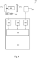
- Figure 4 illustrates an embodiment of a hydraulic power steering system 400 in a vehicle 100.
- the hydraulic power steering system 400 comprises a primary power steering pump 270a arranged to be driven by the engine 260. Further, the hydraulic power steering system 400 also comprises a secondary power steering pump 270b.
- the hydraulic power steering system 400 furthermore comprises a control arrangement 210.
- the control arrangement 210 is configured to perform at least some of the previously described steps 301-311 according to the method 300 described above and illustrated in Figure 3 , for controlling the vehicle 100 to freewheel with engine off. It will be appreciated that the various embodiments described for the method 300 are all combinable with the control arrangement 210.
- the control arrangement 210 may comprise a receiving circuit 410 configured for receiving a signal from a map database 250, a positioning unit 230, the primary power steering pump 270a, and the secondary power steering pump 270b.
- the control arrangement 210 may also comprise a processing circuitry 420 configured for performing at least some of the calculating or computing of the control arrangement 210.
- the processing circuitry 420 may be configured to determine when to start freewheeling the vehicle 100 with engine off.
- the processing circuitry 420 may also be configured to, prior to starting the freewheeling of the vehicle 100 with engine off, determine to start the secondary power steering pump 270b.
- Such processing circuitry 420 may comprise one or more instances of a processing circuit, i.e. a Central Processing Unit (CPU), a processing unit, a processor, an Application Specific Integrated Circuit (ASIC), a microprocessor, or other processing logic that may interpret and execute instructions.
- a processing circuit i.e. a Central Processing Unit (CPU), a processing unit, a processor, an Application Specific Integrated Circuit (ASIC), a microprocessor, or other processing logic that may interpret and execute instructions.
- CPU Central Processing Unit
- ASIC Application Specific Integrated Circuit
- microprocessor may thus represent a processing circuitry comprising a plurality of processing circuits, such as, e.g., any, some or all of the ones enumerated above.
- control arrangement 210 may comprise a memory 425 in some embodiments.
- the optional memory 425 may comprise a physical device utilised to store data or programs, i.e., sequences of instructions, on a temporary or permanent basis.
- the memory 425 may comprise integrated circuits comprising silicon-based transistors.
- the memory 425 may comprise e.g. a memory card, a flash memory, a USB memory, a hard disc, or another similar volatile or non-volatile storage unit for storing data such as e.g. ROM (Read-Only Memory), PROM (Programmable Read-Only Memory), EPROM (Erasable PROM), EEPROM (Electrically Erasable PROM), etc. in different embodiments.
- control arrangement 210 may comprise a signal transmitter 430 .
- the signal transmitter 430 may be configured to transmit a control signal over a wired or wireless interface to be received by the vehicle engine 260, the primary power steering pump 270a, the secondary power steering pump 270b, and/ or the output device 220.
- the output device 220 may comprise e.g. a display, a loudspeaker, a projector, a head-up display, a display integrated in the windshield of the vehicle 100, a display integrated in the dashboard of the vehicle 100, a tactile device, a portable device of the vehicle driver/ owner, intelligent glasses of the vehicle driver/ owner, etc.; or a combination thereof.
- the previously described steps 301-311 to be performed in the control arrangement 210 may be implemented through the one or more processing circuitries 420 within the control arrangement 210, together with computer program product for performing at least some of the functions of the steps 301-311.
- a computer program product comprising instructions for performing the steps 301-311 in the control arrangement 210 may perform the method 300 comprising at least some of the steps 301-311 for controlling a vehicle 100 to freewheel with engine off, when the computer program is loaded into the one or more processing circuitries 420 of the control arrangement 210.
- the computer program mentioned above may be provided for instance in the form of a computer-readable medium carrying instructions in form of a computer program code for performing at least some of the steps 301-311 according to some embodiments when being loaded into the one or more processing circuitries 420 of the control arrangement 210.
- the computer-readable medium may be, e.g., a hard disk, a CD ROM disc, a memory stick, an optical storage device, a magnetic storage device or any other appropriate medium such as a disk or tape that may hold machine readable data in a non-transitory manner.
- the computer program may furthermore be provided as computer program code on a server and downloaded to the control arrangement 210 remotely, e.g., over an Internet or an intranet connection.
- some embodiments may comprise a vehicle 100, comprising the engine 260 and the above described hydraulic power steering system 400.
- the term “and/ or” comprises any and all combinations of one or more of the associated listed items.
- the term “or” as used herein, is to be interpreted as a mathematical OR, i.e., as an inclusive disjunction; not as a mathematical exclusive OR (XOR), unless expressly stated otherwise.
- the singular forms “a”, “an” and “the” are to be interpreted as “at least one”, thus also possibly comprising a plurality of entities of the same kind, unless expressly stated otherwise.
Landscapes
- Engineering & Computer Science (AREA)
- Chemical & Material Sciences (AREA)
- Combustion & Propulsion (AREA)
- Transportation (AREA)
- Mechanical Engineering (AREA)
- Automation & Control Theory (AREA)
- Physics & Mathematics (AREA)
- General Physics & Mathematics (AREA)
- Steering Control In Accordance With Driving Conditions (AREA)
- Power Steering Mechanism (AREA)
- Auxiliary Drives, Propulsion Controls, And Safety Devices (AREA)
- Control Of Vehicle Engines Or Engines For Specific Uses (AREA)
Description
- This document discloses a method and a control arrangement. More particularly, a method and a control arrangement is described, for controlling a vehicle to freewheel with engine off.
- Freewheeling functionality with engine running on idle (and the gearbox in neutral/ open clutch) has been in production for many years in heavy trucks. The later versions are based on look-ahead systems that in advance can calculate the length of the freewheeling based on road gradient data from a map-database.
- While these systems save a lot of fuel, it would be possible to save even more by shutting off the engine completely.
- It is a well-known problem that auxiliary systems in conventional vehicles traditionally have been driven by the engine, which makes shutting-off the engine difficult in situations where the auxiliary systems are required. The most typical case is the power-steering system, that traditionally have been driven directly by the engine.
- A known solution to achieve power steering while the vehicle engine is off, is to replace the engine driven system with an electrical power steering system, and/ or a hydraulic system with two different pumps. A drawback with two pumps is that the losses in the system gets unnecessary large if both pumps are activated continuously.
- A two-pump system may be used in so called dual-circuit steering systems, which generally is installed to achieve power steering redundancy (if the engine mounted pump fails, the engine fails etc.). All known solutions either run the secondary pump continuously, or starts it when it detects a pressure/ flow drop in the primary circuit, i.e. after the engine is shut off. Document
US 2012/0160594 A1 discloses a power steering system which obtains an assistance force of a steering operation according to an actuation of a pump. The power steering system comprises a first pump associated with a combustion engine and a second pump associated with an electric motor. Furthermore, documentDE 10 2016 009342 A1 discloses the preamble of the independent claims. - It would be desirable to further explore and develop power steering of vehicles, in particular in freewheeling scenarios, with the engine switched off.
- A drawback with the solution presented in the prior art is that there is an interruption in power steering performance when the engine is turned off, before the second pump is started, which may affect the steering and in a worst-case scenario cause an accident. Further, there is no solution provided in case the second pump (or the associated electric motor) does not work properly, resulting in a malfunctioning power steering performance; which again potentially may cause an accident. Yet a disadvantage of the enumerated briefly described systems require pressure/ flow sensors in order to detect when to start the secondary pump.
- It would be advantageous to achieve a method and a control arrangement overcoming, or at least alleviating, at least some of the above-mentioned drawback(s). In particular, it would be desirable to enable for improving power steering when freewheeling a vehicle with engine off. To better address one or more of these concerns, a method and a control arrangement having the features defined in the independent claim(s) are provided.
- According to a first aspect of the invention, this object is achieved by a method for controlling a vehicle to freewheel with engine off. The vehicle comprising an engine for propelling the vehicle and a hydraulic power steering system. The hydraulic power steering system comprises a primary power steering pump arranged to be driven by the engine and a secondary power steering pump. The method comprises determining when to start freewheeling the vehicle with engine off. Further, the method also comprises, prior to starting the freewheeling of the vehicle with engine off, determining to start the secondary power steering pump.
- Further, the method comprises determining if the secondary power steering pump is functioning and inhibiting start of freewheeling the vehicle with engine off when it cannot be determined that the secondary power steering pump is functioning.
- According to a second aspect of the invention, this object is achieved by a control arrangement for controlling a vehicle to freewheel with engine off. The vehicle comprising an engine for propelling the vehicle and a hydraulic power steering system. The hydraulic power steering system comprises a primary power steering pump arranged to be driven by the engine, and a secondary power steering pump. The control arrangement is configured to determine when to start freewheeling the vehicle with engine off. Further, the control arrangement is configured to, prior to starting the freewheeling of the vehicle with engine off, determine to start the secondary power steering pump. Further, the control arrangement is configured to determine if the secondary power steering pump is functioning and inhibit start of freewheeling the vehicle with engine off when it cannot be determined that the secondary power steering pump is functioning.
- Thanks to the described aspects, by determining to start the secondary power steering pump before starting the freewheeling of the vehicle with engine off, it becomes possible to turn the engine off without losing power steering assistance. It is thereby possible to save fuel in comparison with freewheeling with the engine running on idle, and yet provide a seamless transfer of steering feel between being supported by the primary power steering pump and the secondary power steering pump. Yet an advantage is that the provided solution does not require flow and/or pressure sensors in the hydraulic circuit, leading to decreased (or at least not increased) production costs. Thanks to the provided solution, it also becomes possible to diagnose that the secondary power steering pump is working properly before shutting off the engine, and freewheel with the engine running on idle in case the secondary power steering pump is dysfunctional. It is thereby avoided that the driver is left without power steering assistance. Thereby, traffic safety is enhanced, both for the vehicle and other road users, while fuel consumption and combustion engine emissions are reduced. Also, noise pollution from the vehicle engine is eliminated.
- Other advantages and additional novel features will become apparent from the subsequent detailed description.
- Embodiments of the invention will now be described in further detail with reference to the accompanying figures, in which:
- Figure 1A
- illustrates a vehicle according to an embodiment of the invention;
- Figure 1B
- illustrates a vehicle according to an embodiment of the invention;
- Figure 2
- illustrates a vehicle interior according to an embodiment of the invention;
- Figure 3
- is a flow chart illustrating an embodiment of the method;
- Figure 4
- is an illustration depicting a system according to an embodiment.
- Embodiments of the invention described herein are defined as a method and a control arrangement, which may be put into practice in the embodiments described below. These embodiments may, however, be exemplified and realised in many different forms and are not to be limited to the examples set forth herein; rather, these illustrative examples of embodiments are provided so that this disclosure will be thorough and complete.
- Still other objects and features may become apparent from the following detailed description, considered in conjunction with the accompanying drawings. It is to be understood, however, that the drawings are designed solely for purposes of illustration and not as a definition of the limits of the herein disclosed embodiments, for which reference is to be made to the appended claims. Further, the drawings are not necessarily drawn to scale and, unless otherwise indicated, they are merely intended to conceptually illustrate the structures and procedures described herein.
-
Figure 1A illustrates a scenario with avehicle 100, driving in adriving direction 105 on a road. Thevehicle 100 comprises a hydraulic system with two different pumps, one larger primary pump driven by an engine for propelling thevehicle 100, such as e.g. a combustion engine, and one secondary pump, perhaps somewhat smaller than the primary pump, driven for example by an electric motor. - The
vehicle 100 may comprise e.g. a truck, a bus, a car, a motorcycle or any similar vehicle or other means of conveyance. Thevehicle 100 may be driver controlled or a driverless autonomously controlled vehicle in different embodiments. However, for enhanced clarity, thevehicle 100 is subsequently described as having a driver. -
Figure 1B illustrates an example of a scenario where thevehicle 100 presented inFigure 1A have arrived at a hilly region. - When arriving at a downhill slope at a first moment α, the
vehicle 100 may activate an engine independent power steering functionality and then shut off the engine during driving for freewheeling, in order to save fuel, until the freewheeling is abandoned at a second moment β. - The
vehicle 100 is equipped with a hydraulic power steering system comprising two independent power steering pumps. The primary pump may be driven by the combustion engine while the secondary pump could either be driven by an electric motor or driven from the vehicle transmission e.g. lay-shaft or main-shaft in a gearbox of thevehicle 100. At least the secondary pump is possible to inactivate in some way, e.g. by shutting down the electric motor, disconnect it mechanically with a clutch, or bypass it hydraulically with a valve, for example. - In order to avoid unnecessary losses in the power steering system it is important only to have one pump active at the same time; although in some cases it could maybe be beneficial to use both pumps, e.g. dry park manoeuvring. The herein described concept comprises engaging the secondary pump just before a freewheeling situation with engine off, and disable it right after the engine has started.
- The advantage of this, compared with previously known technology that starts the secondary pump after the engine already have stopped, is that it also allows for diagnosis of the secondary steering pump before the engine shuts down. Further, it also gives a seamless transition in steering feel.
- Since the primary pump is driven directly by the engine, it is not an option to use it when the engine is stopped during freewheeling. It is therefore imperative to determine to engage the secondary pump before shutting off the engine. This may in many cases be beneficial to do as late as possible, in order to minimise losses. Hence, the engine start-stop sequence may look like this, in some embodiments, although the sequential order for at least some of the described steps may be altered.
- It may be identified that it is possible to freewheel (with any type of algorithm, e.g. look-ahead based), thereby detecting a downhill sequence which is long enough. Thereafter, or simultaneously, or even somewhat before the previous method step, it may be determined that engine shutdown is possible, e.g. by checking temperatures, battery status etc. and estimating length of freewheeling, etc. In case freewheeling -with engine off- is determined to be possible, it may be determined to start the secondary power steering pump. In some embodiments, the secondary pump and its functionality may be diagnosed. The engine may then be shut off and the freewheeling with engine off may commence, possibly when it has been confirmed that the secondary pump is operable.
- When the
freewheeling vehicle 100 is reaching the end of the downhill at the second moment β, the engine of thevehicle 100 may be started, based on any type of algorithm. Then, it may be determined to shut off the secondary power steering pump. In some embodiments, it may be determined to diagnose that the primary pump is working before determining to shutting it off. - The described sequence of actions, or parts thereof, may be implemented together with a look-ahead system, which gives the possibility to start the secondary pump just before the freewheeling optimally is activated and therefore maximise engine-off time, but the sequence itself is relevant for any type of freewheeling algorithm.
- Advantages of the herein described embodiments comprises saving fuel in comparison with a system running two pumps constantly. Another advantage is that a seamless transfer of steering feel is provided, compared to a system that starts the secondary pump after the engine have stopped. Yet an advantage is that it does not require flow and/ or pressure sensors in the hydraulic circuit. Further, some of the described embodiments provide a possibility to diagnose that the secondary pump is working properly before shutting off the engine. It may thereby be avoided that the engine, and thereby also the primary pump, is shut off in a scenario when the secondary pump is dysfunctional; which would leave the driver without power steering assistance.
-
Figure 2 illustrates an example of how the previously scenario inFigure 1A and Figure 1B may be perceived by the driver of thevehicle 100. - The
vehicle 100 comprises acontrol arrangement 210 configured for controlling avehicle 100 to freewheel with engine off. Thecontrol arrangement 210 may comprise one control unit, or a plurality of control units in different embodiments. In some embodiments, anoutput device 220 may be comprised in thevehicle 100, connected to or associated with thecontrol arrangement 210. - The
optional output device 220 may comprise e.g. a display, a loudspeaker, a projector, a head-up display, a display integrated in the windshield of thevehicle 100, a display integrated in the dashboard of thevehicle 100, a tactile device, a portable device of the vehicle driver/ owner, a set of close-eyes displays (i.e. intelligent glasses) of the vehicle driver/ owner, etc.; or a combination thereof. - Various information related to freewheeling and e.g. saved fuel associated therewith may thereby be outputted to the driver. Further, the driver may be provided an option to override a freewheeling decision, e.g. in case the driver plan to leave the route in a downhill passage, etc.
- The
control arrangement 210 may be configured for look-ahead prediction of the route of thevehicle 100. Such look-ahead prediction may be based on determination of current position and drivingdirection 105 of thevehicle 100, and knowledge of topographic data of the road ahead of thevehicle 100. - For the purpose of determining current position, the
vehicle 100 may comprise apositioning unit 230. Thepositioning unit 230 may be based on a satellite navigation system such as the Navigation Signal Timing and Ranging (Navstar) Global Positioning System (GPS), Differential GPS (DGPS), Galileo, GLONASS, or the like. Thus, thepositioning unit 230 may comprise a GPS receiver. - The geographical position of the
vehicle 100 may be determined continuously or at certain predetermined or configurable time intervals according to various embodiments. - Positioning by satellite navigation is based on distance measurement using triangulation from a number of
satellites satellites satellite satellite GPS satellites individual satellite respective satellite positioning unit 230 in thevehicle 100. - Distance measurement can according to some embodiments comprise measuring the difference in the time it takes for each respective satellite signal transmitted by the
respective satellites positioning unit 230. As the radio signals travel at the speed of light, the distance to therespective satellite - The positions of the
satellites vehicle 100 may be calculated by determining the distance to at least threesatellites satellites direction 105 may be determined. - Having determined the geographical position of the
vehicle 100, and also determined the drivingdirection 105 of thevehicle 100, thecontrol arrangement 210 may extract a road slope at a geographical position of the road in front of thevehicle 100 in thedetermined driving direction 105. This position, i.e. the geographical position in front of thevehicle 100 where the road slope is determined, may be configurable by the driver in some embodiments, and/ or may be dependent of the speed of thevehicle 100, such that low speed is associated with a short distance ahead and high speed is associated with a long distance ahead, in some embodiments. - The road slope at the geographical position of the road 120 in front of the
vehicle 100 may be extracted from adatabase 250. Thedatabase 250 may be situated within thevehicle 100 in some embodiments, or alternatively be external to thevehicle 100, and accessible by the look-ahead prediction functionality. - In the
database 250, different geographical positions are stored associated with topographic data, such as road slope values, or height; which may be extracted from thedatabase 250 by using a geographical position and a drivingdirection 105 of thevehicle 100, as input values. - The
vehicle 100 comprises anengine 260 for propelling thevehicle 100 and a hydraulic power steering system, in turn comprising a primarypower steering pump 270a arranged to be driven by theengine 260, and a secondarypower steering pump 270b. The secondarypower steering pump 270b may be driven by anelectric motor 280 in some embodiments. However, in other embodiments, the secondarypower steering pump 270b may be mechanically driven by hydraulic bypass and/ or driven by a shaft of a gearbox of thevehicle 100, which shaft may be arranged to be disengaged from theengine 260 during freewheeling. Theengine 260 may comprise a combustion engine such as a diesel engine, a gasoline engine or an engine driven by biofuel (non-limiting examples). - The
control arrangement 210 is configured to determine when to start freewheeling thevehicle 100 with engine off, e.g. based on the made look-ahead prediction. Further, thecontrol arrangement 210 is configured to determine to start the secondarypower steering pump 270b, prior to starting the freewheeling of thevehicle 100 with engine off. - The enumerated
entities vehicle 100 may interactively communicate between themselves via e.g. a wired or wireless communication bus. The communication bus may comprise e.g. a Controller Area Network (CAN) bus, a Media Oriented Systems Transport (MOST) bus, Ethernet or similar. However, the communication may alternatively be made over a wireless connection such as Wifi, Bluetooth, etc. -
Figure 3 illustrates an example of amethod 300 according to an embodiment. The flow chart inFigure 3 shows themethod 300 in avehicle 100 comprising anengine 260 for propelling thevehicle 100 and a hydraulic power steering system. The hydraulic power steering system comprises a primarypower steering pump 270a arranged to be driven by theengine 260 and a secondarypower steering pump 270b. The secondarypower steering pump 270b may be arranged to be driven separately from theengine 260, e.g. by anelectric motor 280. - The
method 300 aims at controlling freewheeling with engine off, of thevehicle 100. - The
vehicle 100 may be any arbitrary kind of means for conveyance on land, such as a truck, a bus, a car, a train, etc. - In order to correctly be able to control vehicle freewheeling, the
method 300 may comprise a number of steps 301-311. However, some of these steps 301-311 may be performed solely in some alternative embodiments, such as e.g. steps 303-311. Further, the described steps 301-311 may be performed in a somewhat different chronological order than the numbering suggests. The steps 301-311 of themethod 300 may be performed automatically. Themethod 300 may comprise the subsequent steps:
Step 301 comprises determining when to start freewheeling thevehicle 100 with engine off. - The determination of when to start freewheeling the
vehicle 100 with engine off may be made based on a look ahead algorithm using topographic data of a planned route of thevehicle 100, and geographic position of thevehicle 100, in some embodiments. - Step 302 comprises, prior to starting the freewheeling of the
vehicle 100 with engine off, determining to start the secondarypower steering pump 270b. - In some embodiments, a point in time when determining to start the secondary
power steering pump 270b may be selected based on: required time to increase pressure/ flow in the secondarypower steering pump 270b, up to a threshold level; and/ or time for theengine 260 to drop speed from current speed to the threshold limit speed. - In some embodiments, the secondary
power steering pump 270b may be started before theengine 260 is turned off. However, in other embodiments only the decision to start the secondarypower steering pump 270b is made before theengine 260 is turned off while the secondarypower steering pump 270b may be started after theengine 260 has been turned off, or simultaneously with turning off theengine 260. -
Step 303, which only may be performed in some embodiments, comprises determining if the secondarypower steering pump 270b is functioning. - The determination if the secondary
power steering pump 270b is functioning may in some embodiments comprise performing a diagnosis based on one or more of: measuring pressure and/ or flow in the secondarypower steering pump 270b; checking that the secondarypower steering pump 270b is rotating; checking whether a valve of the secondarypower steering pump 270b is closed/ open; measuring that a clutch has been closed; and/ or measuring current/ voltage to an electric machine. - In case it could not be determined that the secondary
power steering pump 270b is functioning correctly, thevehicle 100 may still freewheel, but with the engine running. The steering is then assisted by the primarypower steering pump 270a. -
Step 304, which only may be performed in some embodiments whereinstep 303 has been performed, comprises inhibiting starting freewheeling thevehicle 100 with engine off when it cannot be determined 303 that the secondarypower steering pump 270b is functioning. - In such case, the
vehicle 100 may still freewheel, but with theengine 260 running in idle mode. -
Step 305, which only may be performed in some embodiments, comprises shutting off theengine 260 of thevehicle 100. - Shutting off the
engine 260 may mean cutting the fuel supply. -
Step 306, which only may be performed in some embodiments whereinstep 305 has been performed, comprises starting the secondarypower steering pump 270b, before the engine speed of theengine 260 falls below a threshold limit speed. - When the
engine 260 is turned off, it will take some time period, e.g. some seconds the engine speed to fall from the cruising speed, to zero. The secondarypower steering pump 270b may in some embodiments occur before the primarypower steering pump 270a no longer supply enough pressure/ flow, but not necessarily before closing of engine fuelling. In some embodiments, the secondarypower steering pump 270b may be started when passing a critical engine speed, such as e.g. idling revolutions or an engine speed which gives enough power steering performance. - The critical engine speed may thus be determined as e.g. the lowest engine speed providing enough power enabling the primary
power steering pump 270a to operate adequately, idle speed, the minimum speed allowing the engine to re-start theengine 260 with fuel only, and/ or 0 rpm, in different embodiments. - In some embodiments, the moment in time when the secondary
power steering pump 270b is to be started, may be set based on: a time period required to increase pressure/ flow up to a predefined level, how fast the engine speed of theengine 260 drops when the fuel supply is interrupted, current engine speed, and/ or a critical speed when the secondarypower steering pump 270b is required to be running. -
Step 307, which only may be performed in some embodiments, comprises controlling thevehicle 100 to start freewheeling with engine off. -
Step 308, which only may be performed in some embodiments, comprises determining when to discontinue freewheeling thevehicle 100 with engine off. - This decision may be made based on input from a route prediction and retrieved topographic data e.g., when it is predicted that the downhill levels out.
-
Step 309, which only may be performed in some embodiments whereinstep 308 has been performed, comprises starting theengine 260 and the primarypower steering pump 270a. -
Step 310, which only may be performed in some embodiments, comprises determining that the primarypower steering pump 270a is functioning. - By performing a check whether the primary
power steering pump 270a is functioning before deactivating the secondarypower steering pump 270b, it is avoided that the driver is without power steering assistance. - Step 311, which only may be performed in some embodiments wherein
step 310 has been performed, comprises keeping the secondarypower steering pump 270b activated when it cannot be determined 310 that the primarypower steering pump 270a is functioning. - In case it could be determined 310 that the primary
power steering pump 270a is functioning, the secondarypower steering pump 270b may be turned off. -
Step 312, which only may be performed in some embodiments whereinstep 308 and step 309 has been performed, comprises shutting off the secondarypower steering pump 270b.Figure 4 illustrates an embodiment of a hydraulicpower steering system 400 in avehicle 100. The hydraulicpower steering system 400 comprises a primarypower steering pump 270a arranged to be driven by theengine 260. Further, the hydraulicpower steering system 400 also comprises a secondarypower steering pump 270b. - The hydraulic
power steering system 400 furthermore comprises acontrol arrangement 210. Thecontrol arrangement 210 is configured to perform at least some of the previously described steps 301-311 according to themethod 300 described above and illustrated inFigure 3 , for controlling thevehicle 100 to freewheel with engine off. It will be appreciated that the various embodiments described for themethod 300 are all combinable with thecontrol arrangement 210. - The
control arrangement 210 may comprise a receivingcircuit 410 configured for receiving a signal from amap database 250, apositioning unit 230, the primarypower steering pump 270a, and the secondarypower steering pump 270b. - The
control arrangement 210 may also comprise aprocessing circuitry 420 configured for performing at least some of the calculating or computing of thecontrol arrangement 210. Thus, theprocessing circuitry 420 may be configured to determine when to start freewheeling thevehicle 100 with engine off. In addition, theprocessing circuitry 420 may also be configured to, prior to starting the freewheeling of thevehicle 100 with engine off, determine to start the secondarypower steering pump 270b. -
Such processing circuitry 420 may comprise one or more instances of a processing circuit, i.e. a Central Processing Unit (CPU), a processing unit, a processor, an Application Specific Integrated Circuit (ASIC), a microprocessor, or other processing logic that may interpret and execute instructions. The herein utilised expression "processor" may thus represent a processing circuitry comprising a plurality of processing circuits, such as, e.g., any, some or all of the ones enumerated above. - Furthermore, the
control arrangement 210 may comprise amemory 425 in some embodiments. Theoptional memory 425 may comprise a physical device utilised to store data or programs, i.e., sequences of instructions, on a temporary or permanent basis. According to some embodiments, thememory 425 may comprise integrated circuits comprising silicon-based transistors. Thememory 425 may comprise e.g. a memory card, a flash memory, a USB memory, a hard disc, or another similar volatile or non-volatile storage unit for storing data such as e.g. ROM (Read-Only Memory), PROM (Programmable Read-Only Memory), EPROM (Erasable PROM), EEPROM (Electrically Erasable PROM), etc. in different embodiments. - Further, the
control arrangement 210 may comprise asignal transmitter 430. Thesignal transmitter 430 may be configured to transmit a control signal over a wired or wireless interface to be received by thevehicle engine 260, the primarypower steering pump 270a, the secondarypower steering pump 270b, and/ or theoutput device 220. - The
output device 220 may comprise e.g. a display, a loudspeaker, a projector, a head-up display, a display integrated in the windshield of thevehicle 100, a display integrated in the dashboard of thevehicle 100, a tactile device, a portable device of the vehicle driver/ owner, intelligent glasses of the vehicle driver/ owner, etc.; or a combination thereof. - The previously described steps 301-311 to be performed in the
control arrangement 210 may be implemented through the one ormore processing circuitries 420 within thecontrol arrangement 210, together with computer program product for performing at least some of the functions of the steps 301-311. Thus, a computer program product, comprising instructions for performing the steps 301-311 in thecontrol arrangement 210 may perform themethod 300 comprising at least some of the steps 301-311 for controlling avehicle 100 to freewheel with engine off, when the computer program is loaded into the one ormore processing circuitries 420 of thecontrol arrangement 210. - The computer program mentioned above may be provided for instance in the form of a computer-readable medium carrying instructions in form of a computer program code for performing at least some of the steps 301-311 according to some embodiments when being loaded into the one or
more processing circuitries 420 of thecontrol arrangement 210. The computer-readable medium may be, e.g., a hard disk, a CD ROM disc, a memory stick, an optical storage device, a magnetic storage device or any other appropriate medium such as a disk or tape that may hold machine readable data in a non-transitory manner. The computer program may furthermore be provided as computer program code on a server and downloaded to thecontrol arrangement 210 remotely, e.g., over an Internet or an intranet connection. - Further, some embodiments may comprise a
vehicle 100, comprising theengine 260 and the above described hydraulicpower steering system 400. - The terminology used in the description of the embodiments as illustrated in the accompanying drawings is not intended to be limiting of the described
method 300; thecontrol arrangement 210; the hydraulicpower steering system 400, the computer program, the computer-readable medium, and/ or thevehicle 100. Various changes, substitutions or alterations may be made, without departing from invention embodiments as defined by the appended claims. - As used herein, the term "and/ or" comprises any and all combinations of one or more of the associated listed items. The term "or" as used herein, is to be interpreted as a mathematical OR, i.e., as an inclusive disjunction; not as a mathematical exclusive OR (XOR), unless expressly stated otherwise. In addition, the singular forms "a", "an" and "the" are to be interpreted as "at least one", thus also possibly comprising a plurality of entities of the same kind, unless expressly stated otherwise. It will be further understood that the terms "includes", "comprises", "including" or "comprising", specifies the presence of stated features, actions, integers, steps, operations, elements, or components, but do not preclude the presence or addition of one or more other features, actions, integers, steps, operations, elements, components, or groups thereof. A single unit such as e.g. a processor may fulfil the functions of several items recited in the claims. The mere fact that certain measures are recited in mutually different dependent claims does not indicate that a combination of these measures cannot be used to advantage. A computer program may be stored/ distributed on a suitable medium, such as an optical storage medium or a solid-state medium supplied together with or as part of other hardware, but may also be distributed in other forms such as via Internet or other wired or wireless communication system.
Claims (15)
- A method (300) for controlling a vehicle (100) to freewheel with engine off,the vehicle (100) comprising an engine (260) for propelling the vehicle (100) and a hydraulic power steering system (400);which hydraulic power steering system (400) comprises a primary power steering pump (270a) arranged to be driven by the engine (260) and a secondary power steering pump (270b);wherein the method (300) comprises:- determining (301) when to start freewheeling the vehicle (100) with engine off;
characterized by, that the method further comprises;- prior to starting the freewheeling of the vehicle (100) with engine off, determining (302) to start the secondary power steering pump (270b),- determining (303) if the secondary power steering pump (270b) is functioning; and- inhibiting (304) start of freewheeling the vehicle (100) with engine off when it cannot be determined (303) that the secondary power steering pump (270b) is functioning. - The method (300) according to claim 1, wherein the determination (303) if the secondary power steering pump (270b) is functioning comprises performing a diagnosis based on one or more of:measuring pressure and/ or flow in the secondary power steering pump (270b);checking that the secondary power steering pump (270b) is rotating;checking whether a valve of the secondary power steering pump (270b) is closed/ open;measuring that a clutch has been closed;measuring current/ voltage to an electric machine.
- The method (300) according to any one of the preceding claims, wherein the determination (301) of when to start freewheeling the vehicle (100) with engine off is made based on a look ahead algorithm using topographic data of a planned route of the vehicle (100), and geographic position of the vehicle (100).
- The method (300) according to any one of the preceding claims, wherein the secondary power steering pump (270b) is arranged to be driven separately from the engine (260).
- The method (300) according to any one of the preceding claims, further comprising:- determining (308) when to discontinue freewheeling the vehicle (100) with engine off; and, based on that:- starting (309) the engine (260) and the primary power steering pump (270a); and- shutting off (312) the secondary power steering pump (270b).
- The method (300) according to claim 5, further comprising:- determining (310) if the primary power steering pump (270a) is functioning; and- keeping (311) the secondary power steering pump (270b) activated when it cannot be determined (310) that the primary power steering pump (270a) is functioning.
- The method (300) according to any one of the preceding claims, further comprising:- shutting off (305) the engine (260) of the vehicle (100);- starting (306) the secondary power steering pump (270b), before the engine speed of the engine (260) falls below a threshold limit speed.
- The method (300) according to claim 7, wherein a point in time when determining (302) to start the secondary power steering pump (270b) is selected based on:required time to increase pressure/ flow in the secondary power steering pump (270b), up to a threshold level; andtime for the engine (260) to drop speed from current speed to the threshold limit speed.
- The method (300) according to any one of the preceding claims, further comprising:- controlling (307) the vehicle (100) to start freewheeling with engine off.
- The method (300) according to any one of the preceding claims, wherein the steps of the method (300) are performed automatically.
- A computer program comprising instructions which, when the program is executed by a computer, cause the computer to carry out the steps of the method (300) according to any one of the preceding claims.
- A computer-readable medium, comprising instructions which, when executed by a computer, cause the computer to carry out the steps of the method (300) according to any one of claims 1-10.
- A control arrangement (210) for controlling a vehicle (100) to freewheel with engine off,the vehicle (100) comprising an engine (260) for propelling the vehicle (100) and a hydraulic power steering system (400);which hydraulic power steering system (400) comprises a primary power steering pump (270a) arranged to be driven by the engine (260), and a secondary power steering pump (270b);wherein the control arrangement (210) is configured to:determine when to start freewheeling the vehicle (100) with engine off; characterized in that, the control arrangement is further configured to;prior to starting the freewheeling of the vehicle (100) with engine off, determine to start the secondary power steering pump (270b),determine if the secondary power steering pump (270b) is functioning; and- inhibit start of freewheeling the vehicle (100) with engine off when it cannot be determined that the secondary power steering pump (270b) is functioning.
- A hydraulic power steering system (400) comprising:a control arrangement (210) according to claim 13;a primary power steering pump (270a) arranged to be driven by the engine (260); anda secondary power steering pump (270b).
- A vehicle (100) comprising an engine (260) and a hydraulic power steering system (400) according to claim 14.
Applications Claiming Priority (2)
| Application Number | Priority Date | Filing Date | Title |
|---|---|---|---|
| SE1750472A SE541356C2 (en) | 2017-04-21 | 2017-04-21 | Method and control arrangement for controlling vehicle free-wheel with engine off and power steering |
| PCT/SE2018/050243 WO2018194500A1 (en) | 2017-04-21 | 2018-03-13 | Method and control arrangement for controlling vehicle freewheel with engine off and power steering |
Publications (3)
| Publication Number | Publication Date |
|---|---|
| EP3612434A1 EP3612434A1 (en) | 2020-02-26 |
| EP3612434A4 EP3612434A4 (en) | 2020-12-23 |
| EP3612434B1 true EP3612434B1 (en) | 2023-09-20 |
Family
ID=63856731
Family Applications (1)
| Application Number | Title | Priority Date | Filing Date |
|---|---|---|---|
| EP18787272.6A Active EP3612434B1 (en) | 2017-04-21 | 2018-03-13 | Method and control arrangement for controlling vehicle freewheel with engine off and power steering |
Country Status (7)
| Country | Link |
|---|---|
| US (1) | US11560173B2 (en) |
| EP (1) | EP3612434B1 (en) |
| KR (1) | KR20190137878A (en) |
| CN (1) | CN110494343A (en) |
| BR (1) | BR112019018309A2 (en) |
| SE (1) | SE541356C2 (en) |
| WO (1) | WO2018194500A1 (en) |
Families Citing this family (4)
| Publication number | Priority date | Publication date | Assignee | Title |
|---|---|---|---|---|
| SE544330C2 (en) * | 2020-08-27 | 2022-04-12 | Scania Cv Ab | Control device, method computer program and computer readable medium for enabling power steering of a vehicle |
| EP4273026B1 (en) * | 2022-05-06 | 2025-12-10 | Volvo Truck Corporation | An auxiliary pump arrangement and a power steering system comprising such auxiliary pump arrangement |
| AT17931U1 (en) * | 2022-08-30 | 2023-08-15 | Wacker Neuson Linz Gmbh | Device for steering a wheel-driven mobile working machine |
| EP4378797B1 (en) * | 2022-11-29 | 2026-03-11 | Volvo Truck Corporation | Hydraulic power steering system |
Family Cites Families (20)
| Publication number | Priority date | Publication date | Assignee | Title |
|---|---|---|---|---|
| JP3867521B2 (en) | 2000-09-05 | 2007-01-10 | トヨタ自動車株式会社 | Electric oil pump control device |
| JP2002249057A (en) | 2001-02-22 | 2002-09-03 | Toyota Motor Corp | Vehicle steering system |
| SE525309C2 (en) | 2004-03-09 | 2005-01-25 | Volvo Lastvagnar Ab | Automatic freewheel method for lorry with automatic gearbox, deactivates freewheeling and activating brakes when given maximum vehicle speed is exceeded |
| JP4111191B2 (en) | 2004-12-28 | 2008-07-02 | 日産自動車株式会社 | Vehicle steering system |
| US7225894B2 (en) * | 2005-01-27 | 2007-06-05 | Trw Automotive U.S. Llc | Power steering apparatus |
| US20080277187A1 (en) * | 2007-05-11 | 2008-11-13 | Trw Automotive U.S. Llc | Power steering apparatus |
| CN101725708B (en) | 2008-10-24 | 2013-09-04 | 通用汽车环球科技运作公司 | Method for controlling hydraulic pipeline pressure of hydraulic control system in electromechanical transmitor |
| EP2427358B1 (en) | 2009-05-08 | 2019-03-20 | Volvo Lastvagnar AB | Method and device for controlling an automatic freewheeling function in a vehicle |
| KR101370168B1 (en) | 2009-08-11 | 2014-03-04 | 현대중공업 주식회사 | Power handle control method of wheel excavator by pressure sensor of the steering unit |
| EP2598393B1 (en) * | 2010-07-28 | 2017-09-06 | Volvo Lastvagnar AB | Power steering system for a vehicle |
| JP5526006B2 (en) | 2010-11-25 | 2014-06-18 | ジヤトコ株式会社 | Coast stop vehicle and coast stop vehicle control method |
| JP5276088B2 (en) * | 2010-12-24 | 2013-08-28 | 日立オートモティブシステムズステアリング株式会社 | Power steering device |
| SE537676C2 (en) * | 2011-06-10 | 2015-09-29 | Scania Cv Ab | Procedure and system for driving a vehicle |
| JP5607583B2 (en) | 2011-07-12 | 2014-10-15 | 日立オートモティブシステムズステアリング株式会社 | Power steering device |
| SE538472C2 (en) | 2012-06-27 | 2016-07-12 | Scania Cv Ab | Control of locking means in planetary gear by means of an electric machine |
| DE102012217250A1 (en) | 2012-09-25 | 2014-03-27 | Zf Friedrichshafen Ag | Power steering device and method and control device for operating the same |
| KR101394695B1 (en) * | 2012-12-12 | 2014-05-15 | 현대자동차주식회사 | Method for improving steering feel in gear neutral position drivng of vehicle |
| US20150198507A1 (en) * | 2014-01-15 | 2015-07-16 | Caterpillar, Inc. | Increased Pressure for Emergency Steering Pump Startup Test |
| DE102015010574A1 (en) * | 2015-08-12 | 2016-03-24 | Daimler Ag | Method for supporting a steering system of a vehicle in a sailing operation |
| DE102016009342A1 (en) | 2016-08-02 | 2017-02-09 | Daimler Ag | Steering system for a motor vehicle, in particular a motor vehicle |
-
2017
- 2017-04-21 SE SE1750472A patent/SE541356C2/en unknown
-
2018
- 2018-03-13 WO PCT/SE2018/050243 patent/WO2018194500A1/en not_active Ceased
- 2018-03-13 KR KR1020197033450A patent/KR20190137878A/en not_active Ceased
- 2018-03-13 BR BR112019018309-4A patent/BR112019018309A2/en not_active IP Right Cessation
- 2018-03-13 US US16/495,433 patent/US11560173B2/en active Active
- 2018-03-13 EP EP18787272.6A patent/EP3612434B1/en active Active
- 2018-03-13 CN CN201880023971.4A patent/CN110494343A/en active Pending
Also Published As
| Publication number | Publication date |
|---|---|
| BR112019018309A2 (en) | 2020-03-31 |
| EP3612434A1 (en) | 2020-02-26 |
| KR20190137878A (en) | 2019-12-11 |
| SE1750472A1 (en) | 2018-10-22 |
| US20200062302A1 (en) | 2020-02-27 |
| WO2018194500A1 (en) | 2018-10-25 |
| CN110494343A (en) | 2019-11-22 |
| US11560173B2 (en) | 2023-01-24 |
| EP3612434A4 (en) | 2020-12-23 |
| SE541356C2 (en) | 2019-08-13 |
Similar Documents
| Publication | Publication Date | Title |
|---|---|---|
| EP3612434B1 (en) | Method and control arrangement for controlling vehicle freewheel with engine off and power steering | |
| US9121356B2 (en) | Stop/start control to increase microhybrid vehicle battery charge | |
| US10793134B2 (en) | Vehicle coasting systems and methods | |
| US9045134B2 (en) | Method and systems for emissions compliant use of telematics inputs to a propulsion control system for function enablement | |
| CN104044574B (en) | Automatic start-stop vehicle is controlled when close to controlled intersection | |
| US9664136B2 (en) | Auto-stop control for a stop/start vehicle near water | |
| US20100305805A1 (en) | Vehicle status monitoring apparatus | |
| US20100191446A1 (en) | Systems and methods for predictive engine re-starting and predictive neutral/idle operation of a vehicle | |
| US8936531B2 (en) | Stop-in-park control for micro-hybrid vehicles | |
| GB2567009A (en) | Method of assisting in the control of a prime mover of a vehicle, apparatus for assisting in the control of a prime mover of a vehicle, and a vehicle | |
| CN103802820A (en) | Assisted direct start and active suspension integration control | |
| US20140324305A1 (en) | System and method for operating an engine of a vehicle | |
| US9243570B2 (en) | Auto-stop control for a stop/start vehicle at a service location | |
| US8878481B2 (en) | Method and apparatus for limiting in-rush current to a starter motor of a vehicle | |
| KR20200045939A (en) | Method and system for controlling vehicle idle stop and go | |
| US20230062344A1 (en) | Vehicle control device | |
| JP2014526636A (en) | Drive system control system | |
| JP2010053867A (en) | Engine start/stop unit for automatic-supply/intercept of internal combustion engine | |
| CN104554270B (en) | Automatic start-stop vehicle is automatically stopped control in service position | |
| US10704520B2 (en) | Method and system for controlling activation of vehicle engine idle stop and go | |
| WO2020072828A1 (en) | System and method for prioritizing cylinder de-activation of an engine | |
| KR101714255B1 (en) | A method for selecting a start up method when ssc release and an apparatus therefor | |
| US20220111890A1 (en) | Method for controlling a steering assist system of a vehicle | |
| US9580064B2 (en) | Method and system for controlling fuel pump for hybrid diesel vehicle | |
| EP4494960B1 (en) | Cruise controller |
Legal Events
| Date | Code | Title | Description |
|---|---|---|---|
| STAA | Information on the status of an ep patent application or granted ep patent |
Free format text: STATUS: THE INTERNATIONAL PUBLICATION HAS BEEN MADE |
|
| PUAI | Public reference made under article 153(3) epc to a published international application that has entered the european phase |
Free format text: ORIGINAL CODE: 0009012 |
|
| STAA | Information on the status of an ep patent application or granted ep patent |
Free format text: STATUS: REQUEST FOR EXAMINATION WAS MADE |
|
| 17P | Request for examination filed |
Effective date: 20191121 |
|
| AK | Designated contracting states |
Kind code of ref document: A1 Designated state(s): AL AT BE BG CH CY CZ DE DK EE ES FI FR GB GR HR HU IE IS IT LI LT LU LV MC MK MT NL NO PL PT RO RS SE SI SK SM TR |
|
| AX | Request for extension of the european patent |
Extension state: BA ME |
|
| DAV | Request for validation of the european patent (deleted) | ||
| DAX | Request for extension of the european patent (deleted) | ||
| A4 | Supplementary search report drawn up and despatched |
Effective date: 20201123 |
|
| RIC1 | Information provided on ipc code assigned before grant |
Ipc: B60W 30/18 20120101ALI20201117BHEP Ipc: B62D 5/30 20060101ALI20201117BHEP Ipc: B62D 5/06 20060101AFI20201117BHEP Ipc: B60W 10/20 20060101ALI20201117BHEP |
|
| RAP3 | Party data changed (applicant data changed or rights of an application transferred) |
Owner name: SCANIA CV AB |
|
| GRAP | Despatch of communication of intention to grant a patent |
Free format text: ORIGINAL CODE: EPIDOSNIGR1 |
|
| STAA | Information on the status of an ep patent application or granted ep patent |
Free format text: STATUS: GRANT OF PATENT IS INTENDED |
|
| INTG | Intention to grant announced |
Effective date: 20230424 |
|
| P01 | Opt-out of the competence of the unified patent court (upc) registered |
Effective date: 20230518 |
|
| GRAS | Grant fee paid |
Free format text: ORIGINAL CODE: EPIDOSNIGR3 |
|
| GRAA | (expected) grant |
Free format text: ORIGINAL CODE: 0009210 |
|
| STAA | Information on the status of an ep patent application or granted ep patent |
Free format text: STATUS: THE PATENT HAS BEEN GRANTED |
|
| AK | Designated contracting states |
Kind code of ref document: B1 Designated state(s): AL AT BE BG CH CY CZ DE DK EE ES FI FR GB GR HR HU IE IS IT LI LT LU LV MC MK MT NL NO PL PT RO RS SE SI SK SM TR |
|
| REG | Reference to a national code |
Ref country code: GB Ref legal event code: FG4D |
|
| REG | Reference to a national code |
Ref country code: CH Ref legal event code: EP |
|
| REG | Reference to a national code |
Ref country code: DE Ref legal event code: R096 Ref document number: 602018057956 Country of ref document: DE |
|
| REG | Reference to a national code |
Ref country code: IE Ref legal event code: FG4D |
|
| REG | Reference to a national code |
Ref country code: LT Ref legal event code: MG9D |
|
| PG25 | Lapsed in a contracting state [announced via postgrant information from national office to epo] |
Ref country code: GR Free format text: LAPSE BECAUSE OF FAILURE TO SUBMIT A TRANSLATION OF THE DESCRIPTION OR TO PAY THE FEE WITHIN THE PRESCRIBED TIME-LIMIT Effective date: 20231221 |
|
| REG | Reference to a national code |
Ref country code: NL Ref legal event code: MP Effective date: 20230920 |
|
| PG25 | Lapsed in a contracting state [announced via postgrant information from national office to epo] |
Ref country code: SE Free format text: LAPSE BECAUSE OF FAILURE TO SUBMIT A TRANSLATION OF THE DESCRIPTION OR TO PAY THE FEE WITHIN THE PRESCRIBED TIME-LIMIT Effective date: 20230920 Ref country code: RS Free format text: LAPSE BECAUSE OF FAILURE TO SUBMIT A TRANSLATION OF THE DESCRIPTION OR TO PAY THE FEE WITHIN THE PRESCRIBED TIME-LIMIT Effective date: 20230920 Ref country code: NO Free format text: LAPSE BECAUSE OF FAILURE TO SUBMIT A TRANSLATION OF THE DESCRIPTION OR TO PAY THE FEE WITHIN THE PRESCRIBED TIME-LIMIT Effective date: 20231220 Ref country code: LV Free format text: LAPSE BECAUSE OF FAILURE TO SUBMIT A TRANSLATION OF THE DESCRIPTION OR TO PAY THE FEE WITHIN THE PRESCRIBED TIME-LIMIT Effective date: 20230920 Ref country code: LT Free format text: LAPSE BECAUSE OF FAILURE TO SUBMIT A TRANSLATION OF THE DESCRIPTION OR TO PAY THE FEE WITHIN THE PRESCRIBED TIME-LIMIT Effective date: 20230920 Ref country code: HR Free format text: LAPSE BECAUSE OF FAILURE TO SUBMIT A TRANSLATION OF THE DESCRIPTION OR TO PAY THE FEE WITHIN THE PRESCRIBED TIME-LIMIT Effective date: 20230920 Ref country code: GR Free format text: LAPSE BECAUSE OF FAILURE TO SUBMIT A TRANSLATION OF THE DESCRIPTION OR TO PAY THE FEE WITHIN THE PRESCRIBED TIME-LIMIT Effective date: 20231221 Ref country code: FI Free format text: LAPSE BECAUSE OF FAILURE TO SUBMIT A TRANSLATION OF THE DESCRIPTION OR TO PAY THE FEE WITHIN THE PRESCRIBED TIME-LIMIT Effective date: 20230920 |
|
| REG | Reference to a national code |
Ref country code: AT Ref legal event code: MK05 Ref document number: 1613235 Country of ref document: AT Kind code of ref document: T Effective date: 20230920 |
|
| PG25 | Lapsed in a contracting state [announced via postgrant information from national office to epo] |
Ref country code: NL Free format text: LAPSE BECAUSE OF FAILURE TO SUBMIT A TRANSLATION OF THE DESCRIPTION OR TO PAY THE FEE WITHIN THE PRESCRIBED TIME-LIMIT Effective date: 20230920 |
|
| PG25 | Lapsed in a contracting state [announced via postgrant information from national office to epo] |
Ref country code: IS Free format text: LAPSE BECAUSE OF FAILURE TO SUBMIT A TRANSLATION OF THE DESCRIPTION OR TO PAY THE FEE WITHIN THE PRESCRIBED TIME-LIMIT Effective date: 20240120 |
|
| PG25 | Lapsed in a contracting state [announced via postgrant information from national office to epo] |
Ref country code: AT Free format text: LAPSE BECAUSE OF FAILURE TO SUBMIT A TRANSLATION OF THE DESCRIPTION OR TO PAY THE FEE WITHIN THE PRESCRIBED TIME-LIMIT Effective date: 20230920 |
|
| PG25 | Lapsed in a contracting state [announced via postgrant information from national office to epo] |
Ref country code: ES Free format text: LAPSE BECAUSE OF FAILURE TO SUBMIT A TRANSLATION OF THE DESCRIPTION OR TO PAY THE FEE WITHIN THE PRESCRIBED TIME-LIMIT Effective date: 20230920 |
|
| PG25 | Lapsed in a contracting state [announced via postgrant information from national office to epo] |
Ref country code: SM Free format text: LAPSE BECAUSE OF FAILURE TO SUBMIT A TRANSLATION OF THE DESCRIPTION OR TO PAY THE FEE WITHIN THE PRESCRIBED TIME-LIMIT Effective date: 20230920 Ref country code: RO Free format text: LAPSE BECAUSE OF FAILURE TO SUBMIT A TRANSLATION OF THE DESCRIPTION OR TO PAY THE FEE WITHIN THE PRESCRIBED TIME-LIMIT Effective date: 20230920 Ref country code: IS Free format text: LAPSE BECAUSE OF FAILURE TO SUBMIT A TRANSLATION OF THE DESCRIPTION OR TO PAY THE FEE WITHIN THE PRESCRIBED TIME-LIMIT Effective date: 20240120 Ref country code: ES Free format text: LAPSE BECAUSE OF FAILURE TO SUBMIT A TRANSLATION OF THE DESCRIPTION OR TO PAY THE FEE WITHIN THE PRESCRIBED TIME-LIMIT Effective date: 20230920 Ref country code: EE Free format text: LAPSE BECAUSE OF FAILURE TO SUBMIT A TRANSLATION OF THE DESCRIPTION OR TO PAY THE FEE WITHIN THE PRESCRIBED TIME-LIMIT Effective date: 20230920 Ref country code: CZ Free format text: LAPSE BECAUSE OF FAILURE TO SUBMIT A TRANSLATION OF THE DESCRIPTION OR TO PAY THE FEE WITHIN THE PRESCRIBED TIME-LIMIT Effective date: 20230920 Ref country code: AT Free format text: LAPSE BECAUSE OF FAILURE TO SUBMIT A TRANSLATION OF THE DESCRIPTION OR TO PAY THE FEE WITHIN THE PRESCRIBED TIME-LIMIT Effective date: 20230920 Ref country code: SK Free format text: LAPSE BECAUSE OF FAILURE TO SUBMIT A TRANSLATION OF THE DESCRIPTION OR TO PAY THE FEE WITHIN THE PRESCRIBED TIME-LIMIT Effective date: 20230920 Ref country code: PT Free format text: LAPSE BECAUSE OF FAILURE TO SUBMIT A TRANSLATION OF THE DESCRIPTION OR TO PAY THE FEE WITHIN THE PRESCRIBED TIME-LIMIT Effective date: 20240122 |
|
| PG25 | Lapsed in a contracting state [announced via postgrant information from national office to epo] |
Ref country code: PL Free format text: LAPSE BECAUSE OF FAILURE TO SUBMIT A TRANSLATION OF THE DESCRIPTION OR TO PAY THE FEE WITHIN THE PRESCRIBED TIME-LIMIT Effective date: 20230920 Ref country code: IT Free format text: LAPSE BECAUSE OF FAILURE TO SUBMIT A TRANSLATION OF THE DESCRIPTION OR TO PAY THE FEE WITHIN THE PRESCRIBED TIME-LIMIT Effective date: 20230920 |
|
| REG | Reference to a national code |
Ref country code: DE Ref legal event code: R097 Ref document number: 602018057956 Country of ref document: DE |
|
| PG25 | Lapsed in a contracting state [announced via postgrant information from national office to epo] |
Ref country code: DK Free format text: LAPSE BECAUSE OF FAILURE TO SUBMIT A TRANSLATION OF THE DESCRIPTION OR TO PAY THE FEE WITHIN THE PRESCRIBED TIME-LIMIT Effective date: 20230920 |
|
| PLBE | No opposition filed within time limit |
Free format text: ORIGINAL CODE: 0009261 |
|
| STAA | Information on the status of an ep patent application or granted ep patent |
Free format text: STATUS: NO OPPOSITION FILED WITHIN TIME LIMIT |
|
| PG25 | Lapsed in a contracting state [announced via postgrant information from national office to epo] |
Ref country code: DK Free format text: LAPSE BECAUSE OF FAILURE TO SUBMIT A TRANSLATION OF THE DESCRIPTION OR TO PAY THE FEE WITHIN THE PRESCRIBED TIME-LIMIT Effective date: 20230920 |
|
| 26N | No opposition filed |
Effective date: 20240621 |
|
| PG25 | Lapsed in a contracting state [announced via postgrant information from national office to epo] |
Ref country code: SI Free format text: LAPSE BECAUSE OF FAILURE TO SUBMIT A TRANSLATION OF THE DESCRIPTION OR TO PAY THE FEE WITHIN THE PRESCRIBED TIME-LIMIT Effective date: 20230920 |
|
| PG25 | Lapsed in a contracting state [announced via postgrant information from national office to epo] |
Ref country code: SI Free format text: LAPSE BECAUSE OF FAILURE TO SUBMIT A TRANSLATION OF THE DESCRIPTION OR TO PAY THE FEE WITHIN THE PRESCRIBED TIME-LIMIT Effective date: 20230920 |
|
| REG | Reference to a national code |
Ref country code: CH Ref legal event code: PL |
|
| PG25 | Lapsed in a contracting state [announced via postgrant information from national office to epo] |
Ref country code: BG Free format text: LAPSE BECAUSE OF FAILURE TO SUBMIT A TRANSLATION OF THE DESCRIPTION OR TO PAY THE FEE WITHIN THE PRESCRIBED TIME-LIMIT Effective date: 20230920 |
|
| PG25 | Lapsed in a contracting state [announced via postgrant information from national office to epo] |
Ref country code: LU Free format text: LAPSE BECAUSE OF NON-PAYMENT OF DUE FEES Effective date: 20240313 |
|
| PG25 | Lapsed in a contracting state [announced via postgrant information from national office to epo] |
Ref country code: MC Free format text: LAPSE BECAUSE OF FAILURE TO SUBMIT A TRANSLATION OF THE DESCRIPTION OR TO PAY THE FEE WITHIN THE PRESCRIBED TIME-LIMIT Effective date: 20230920 |
|
| PG25 | Lapsed in a contracting state [announced via postgrant information from national office to epo] |
Ref country code: MC Free format text: LAPSE BECAUSE OF FAILURE TO SUBMIT A TRANSLATION OF THE DESCRIPTION OR TO PAY THE FEE WITHIN THE PRESCRIBED TIME-LIMIT Effective date: 20230920 Ref country code: LU Free format text: LAPSE BECAUSE OF NON-PAYMENT OF DUE FEES Effective date: 20240313 Ref country code: BG Free format text: LAPSE BECAUSE OF FAILURE TO SUBMIT A TRANSLATION OF THE DESCRIPTION OR TO PAY THE FEE WITHIN THE PRESCRIBED TIME-LIMIT Effective date: 20230920 |
|
| PG25 | Lapsed in a contracting state [announced via postgrant information from national office to epo] |
Ref country code: IE Free format text: LAPSE BECAUSE OF NON-PAYMENT OF DUE FEES Effective date: 20240313 |
|
| PG25 | Lapsed in a contracting state [announced via postgrant information from national office to epo] |
Ref country code: IE Free format text: LAPSE BECAUSE OF NON-PAYMENT OF DUE FEES Effective date: 20240313 Ref country code: CH Free format text: LAPSE BECAUSE OF NON-PAYMENT OF DUE FEES Effective date: 20240331 |
|
| PG25 | Lapsed in a contracting state [announced via postgrant information from national office to epo] |
Ref country code: CY Free format text: LAPSE BECAUSE OF FAILURE TO SUBMIT A TRANSLATION OF THE DESCRIPTION OR TO PAY THE FEE WITHIN THE PRESCRIBED TIME-LIMIT; INVALID AB INITIO Effective date: 20180313 |
|
| PG25 | Lapsed in a contracting state [announced via postgrant information from national office to epo] |
Ref country code: HU Free format text: LAPSE BECAUSE OF FAILURE TO SUBMIT A TRANSLATION OF THE DESCRIPTION OR TO PAY THE FEE WITHIN THE PRESCRIBED TIME-LIMIT; INVALID AB INITIO Effective date: 20180313 |
|
| PG25 | Lapsed in a contracting state [announced via postgrant information from national office to epo] |
Ref country code: TR Free format text: LAPSE BECAUSE OF FAILURE TO SUBMIT A TRANSLATION OF THE DESCRIPTION OR TO PAY THE FEE WITHIN THE PRESCRIBED TIME-LIMIT Effective date: 20230920 |
|
| PGFP | Annual fee paid to national office [announced via postgrant information from national office to epo] |
Ref country code: GB Payment date: 20260202 Year of fee payment: 9 |
|
| PGFP | Annual fee paid to national office [announced via postgrant information from national office to epo] |
Ref country code: DE Payment date: 20260204 Year of fee payment: 9 |
|
| PGFP | Annual fee paid to national office [announced via postgrant information from national office to epo] |
Ref country code: BE Payment date: 20260216 Year of fee payment: 9 |
|
| PGFP | Annual fee paid to national office [announced via postgrant information from national office to epo] |
Ref country code: FR Payment date: 20260209 Year of fee payment: 9 |