EP3612010A1 - Retaining tray for retaining an m.2 compatible device used in autonomous driving vehicles - Google Patents
Retaining tray for retaining an m.2 compatible device used in autonomous driving vehicles Download PDFInfo
- Publication number
- EP3612010A1 EP3612010A1 EP19179388.4A EP19179388A EP3612010A1 EP 3612010 A1 EP3612010 A1 EP 3612010A1 EP 19179388 A EP19179388 A EP 19179388A EP 3612010 A1 EP3612010 A1 EP 3612010A1
- Authority
- EP
- European Patent Office
- Prior art keywords
- tray device
- baseboard
- module
- motherboard
- tray
- Prior art date
- Legal status (The legal status is an assumption and is not a legal conclusion. Google has not performed a legal analysis and makes no representation as to the accuracy of the status listed.)
- Granted
Links
Images



Classifications
-
- H—ELECTRICITY
- H05—ELECTRIC TECHNIQUES NOT OTHERWISE PROVIDED FOR
- H05K—PRINTED CIRCUITS; CASINGS OR CONSTRUCTIONAL DETAILS OF ELECTRIC APPARATUS; MANUFACTURE OF ASSEMBLAGES OF ELECTRICAL COMPONENTS
- H05K7/00—Constructional details common to different types of electric apparatus
- H05K7/14—Mounting supporting structure in casing or on frame or rack
- H05K7/1417—Mounting supporting structure in casing or on frame or rack having securing means for mounting boards, plates or wiring boards
- H05K7/142—Spacers not being card guides
-
- B—PERFORMING OPERATIONS; TRANSPORTING
- B60—VEHICLES IN GENERAL
- B60R—VEHICLES, VEHICLE FITTINGS, OR VEHICLE PARTS, NOT OTHERWISE PROVIDED FOR
- B60R16/00—Electric or fluid circuits specially adapted for vehicles and not otherwise provided for; Arrangement of elements of electric or fluid circuits specially adapted for vehicles and not otherwise provided for
- B60R16/02—Electric or fluid circuits specially adapted for vehicles and not otherwise provided for; Arrangement of elements of electric or fluid circuits specially adapted for vehicles and not otherwise provided for electric constitutive elements
-
- B—PERFORMING OPERATIONS; TRANSPORTING
- B60—VEHICLES IN GENERAL
- B60R—VEHICLES, VEHICLE FITTINGS, OR VEHICLE PARTS, NOT OTHERWISE PROVIDED FOR
- B60R11/00—Arrangements for holding or mounting articles, not otherwise provided for
-
- G—PHYSICS
- G06—COMPUTING OR CALCULATING; COUNTING
- G06F—ELECTRIC DIGITAL DATA PROCESSING
- G06F1/00—Details not covered by groups G06F3/00 - G06F13/00 and G06F21/00
- G06F1/16—Constructional details or arrangements
- G06F1/18—Packaging or power distribution
- G06F1/183—Internal mounting support structures, e.g. for supporting printed circuit boards
- G06F1/185—Mounting of expansion boards
-
- H—ELECTRICITY
- H01—ELECTRIC ELEMENTS
- H01R—ELECTRICALLY-CONDUCTIVE CONNECTIONS; STRUCTURAL ASSOCIATIONS OF A PLURALITY OF MUTUALLY-INSULATED ELECTRICAL CONNECTING ELEMENTS; COUPLING DEVICES; CURRENT COLLECTORS
- H01R12/00—Structural associations of a plurality of mutually-insulated electrical connecting elements, specially adapted for printed circuits, e.g. printed circuit boards [PCB], flat or ribbon cables, or like generally planar structures, e.g. terminal strips, terminal blocks; Coupling devices specially adapted for printed circuits, flat or ribbon cables, or like generally planar structures; Terminals specially adapted for contact with, or insertion into, printed circuits, flat or ribbon cables, or like generally planar structures
- H01R12/70—Coupling devices
- H01R12/71—Coupling devices for rigid printing circuits or like structures
-
- H—ELECTRICITY
- H01—ELECTRIC ELEMENTS
- H01R—ELECTRICALLY-CONDUCTIVE CONNECTIONS; STRUCTURAL ASSOCIATIONS OF A PLURALITY OF MUTUALLY-INSULATED ELECTRICAL CONNECTING ELEMENTS; COUPLING DEVICES; CURRENT COLLECTORS
- H01R13/00—Details of coupling devices of the kinds covered by groups H01R12/70 or H01R24/00 - H01R33/00
- H01R13/46—Bases; Cases
- H01R13/50—Bases; Cases formed as an integral body
-
- B—PERFORMING OPERATIONS; TRANSPORTING
- B60—VEHICLES IN GENERAL
- B60R—VEHICLES, VEHICLE FITTINGS, OR VEHICLE PARTS, NOT OTHERWISE PROVIDED FOR
- B60R11/00—Arrangements for holding or mounting articles, not otherwise provided for
- B60R2011/0042—Arrangements for holding or mounting articles, not otherwise provided for characterised by mounting means
- B60R2011/0049—Arrangements for holding or mounting articles, not otherwise provided for characterised by mounting means for non integrated articles
- B60R2011/0064—Connection with the article
- B60R2011/0066—Connection with the article using screws, bolts, rivets or the like
-
- H—ELECTRICITY
- H05—ELECTRIC TECHNIQUES NOT OTHERWISE PROVIDED FOR
- H05K—PRINTED CIRCUITS; CASINGS OR CONSTRUCTIONAL DETAILS OF ELECTRIC APPARATUS; MANUFACTURE OF ASSEMBLAGES OF ELECTRICAL COMPONENTS
- H05K5/00—Casings, cabinets or drawers for electric apparatus
Definitions
- Embodiments of the present invention relate generally to M.2 modules used in autonomous driving vehicles. More particularly, embodiments of the invention relate to a tray device to retain an M.2 module to be utilized in an autonomous driving vehicle.
- Vehicles operating in an autonomous mode can relieve occupants, especially the driver, from some driving-related responsibilities.
- the vehicle can navigate to various locations using onboard sensors, allowing the vehicle to travel with minimal human interaction or in some cases without any passengers.
- an autonomous driving vehicle is controlled by a data processing system that includes various functionalities to perceive a driving environment surrounding the ADV based on sensor data, plan a path to drive the ADV from one point to another point based on the perception information, and to control by issuing proper control commands based on the planning and control data obtained from a variety of sensors (e.g., LIDAR, RADAR, GPS, cameras).
- sensors e.g., LIDAR, RADAR, GPS, cameras.
- M.2 compatible device or module One of the popular modules deployed in an ADV is an M.2 compatible device or module.
- M.2 module is attached to a motherboard of the data processing system, due to the oscillation during the driving of the vehicle, the M.2 module is easily damaged. There has been a lack of efficient ways to reduce the probability of such damage.
- a tray device to retain an M.2 module used in an autonomous driving vehicle includes: a baseboard configured in a relatively rectangular shape having a first and second longitudinal edges and a first and second lateral edges; a first guardrail disposed on a top surface of the baseboard along the first longitudinal edge; a second guardrail disposed on the top surface of the baseboard along the second longitudinal edge, wherein the first and second guardrails are to keep an M.2 module in between and supported by the top surface of the baseboard, while allowing the M.2 module to extend beyond the first and second lateral edges; and a riser member disposed on a bottom surface of the baseboard, wherein when the M.2 module is mounted together with the tray device on a motherboard of a data processing system within an autonomous driving vehicle, the riser member is configured to raise the tray device above the motherboard to prevent the baseboard from applying a heavy pressure on an electronic component mounted on the motherboard and underneath the tray device.
- the M.2 module before an M.2 compatible module or device is mounted onto a data processing system that operates an ADV, the M.2 module is placed onto a tray device to increase the stiffness of the M.2 module.
- the tray device containing the M.2 module is then mounted on a board or motherboard of the data processing system. Since the M.2 module is placed on the tray device, the overall stiffness has been significantly increased, which can sustain the physical impact on the M.2 module due to the physical movement and oscillation or vibration during the autonomous driving of the ADV.
- the tray device also provides a suspension effect on the M.2 module during the movement of the ADV. As a result, the M.2 module would not be easily damaged during the autonomous driving.
- a tray device for retaining an M.2 module includes a baseboard in a relatively rectangular shape, which includes a first and second longitudinal edges or sides and a first and second lateral edges or sides.
- the tray device further includes a first guardrail (also simply referred to as a guard or guard member) disposed on the top surface of the baseboard along the first longitudinal edge and a second guardrail disposed along the second longitudinal edge.
- the first and second guardrails are configured to keep the M.2 module in between and supported by the baseboard, while allowing the M.2 module to extend beyond or across the first and second lateral edges, for example, for mounting purposes.
- the tray device further includes a riser member disposed on the bottom surface of the baseboard (e.g., bottom of the tray device) .
- the riser member is configured to raise the tray device above and away from the motherboard to prevent the baseboard from applying a heavy pressure on an electronic component mounted on the motherboard underneath the tray device, for example, for saving space purpose.
- the M.2 module before mounting the M.2 module on the motherboard, the M.2 module is placed on the top surface of the baseboard and retained between the first and second guardrails. The M.2 module retained by the tray device is then mounted on the motherboard. As a result, the M.2 module would not be bent due to the physical movement or oscillation/vibration during the autonomous driving of the ADV.
- an adhesive strip is placed on the top surface of the baseboard. The adhesive strip is to create an attractive force to draw the M.2 module towards to the top surface of the baseboard. The adhesive strip is utilized to reduce the chances that the M.2 module moves around during the autonomous driving.
- the adhesive strip may be in a form of a foam pad, which further provides suspension and softens the contacting impact between the M.2 module and the baseboard during the autonomous driving.
- another adhesive strip may be placed on the bottom of the riser member to reduce the chances that the tray device moves around on the motherboard.
- the riser member includes a threaded nut or a thread hole molded therein to allow a screw to be inserted from the bottom or opposite side of the motherboard to mount or attach the tray device onto the motherboard.
- tray device 100 includes baseboard 101 in a relatively rectangular shape.
- Baseboard 101 includes a first longitudinal edge (also referred to as a longitudinal side) and a second longitudinal edge such as longitudinal edge 105, substantially in parallel to each other.
- Baseboard 101 further includes a first lateral edge (also referred to as a lateral side) and a second lateral edge such as lateral edge 106, substantially in parallel to each other.
- a first guardrail 102 (also referred to as a retaining member) is disposed or attached to the first longitudinal edge of baseboard 101.
- a second guardrail 103 is disposed or attached to the second longitudinal edge of baseboard 101.
- First guardrail 102, second guardrail 103, and baseboard 101 form a U-shape tray to allow an M.2 module such as M.2 module 500 to be retained therein.
- first guardrail 102, second guardrail 103, and baseboard 101 may be a single piece of material molded into a U-shape retainer tray.
- First guardrail 102 and second guardrail 103 are configured to retain and restrain M.2 module 500 within the tray device 100, while allowing the longitudinal ends of the M.2 module 500 extending across or beyond the lateral edges of baseboard 101 for the purpose of being mounted on the motherboard of the data processing system.
- M.2 module 500 includes a first longitudinal end 501 and a second longitudinal end 502.
- the first longitudinal end 501 includes on the printed circuit board (PCB) an array of electrically conductive pins or pads that can be inserted into an M.2 compatible socket (as shown in Figure 7A ) disposed on the motherboard of the data processing system (e.g., industrial personal computer or IPC) that is utilized to operate an autonomous driving vehicle.
- Second longitudinal end 502 includes a cutout or cavity that allow a screw to be inserted and screwed into a nut or bolt disposed on the motherboard of the data processing system, for example, as shown in Figure 7A .
- M.2 module 500 can be securely mounted onto the motherboard.
- M.2 is a specification for internally mounted computer expansion cards and associated connectors. It replaces the mSATA standard, which uses the PCI Express Mini Card physical card layout and connectors. M.2's more flexible physical specification allows different module widths and lengths, and, paired with the availability of more advanced interfacing features, makes the M.2 more suitable than mSATA for solid-state storage applications in general and particularly for the use in small devices such as ultrabooks or tablets.
- M.2 modules are rectangular, with an edge connector on one side (75 positions with up to 67 pins, 0.5 mm pitch, pins overlap on different sides of the PCB), and a semicircular mounting hole at the center of the opposite edge.
- An M.2 module is installed into a mating connector provided by the host's circuit board, and a single mounting screw secures the module into place.
- Components may be mounted on either side of the module, with the actual module type limiting how thick the components can be; the maximum allowable thickness of components is 1.5 mm per side.
- Different host-side connectors are used for single- and double-sided M.2 modules, providing different amounts of space between the M.2 expansion card and the host's PCB.
- Circuit boards on the hosts are usually designed to accept multiple lengths of M.2 modules, which means that the sockets capable of accepting longer M.2 modules usually also accept shorter ones by providing different positions for the mounting screw.
- An autonomous vehicle refers to a vehicle that can be configured to in an autonomous mode in which the vehicle navigates through an environment with little or no input from a driver.
- Such an autonomous vehicle can include a sensor system having one or more sensors that are configured to detect information about the environment in which the vehicle operates. The vehicle and its associated controller(s) use the detected information to navigate through the environment.
- An autonomous vehicle can operate in a manual mode, a full autonomous mode, or a partial autonomous mode.
- M.2 module 500 can be easily damaged during the physical movement of the vehicle, especially due to the relative movement between the M.2 module 500 and the electronic components mounted on the motherboard beneath the M.2 module 500.
- the stiffness of the M.2 module 500 because the try device 100 provides protection to M.2 module 500 and prevents M.2 module 500 from becoming bended.
- an adhesive strip 104 is disposed on the top surface of baseboard 101.
- the adhesiveness of the adhesive strip 104 creates an attractive force to draw M.2 module 500 towards to the top surface of baseboard 101, which in turn prevent M.2 module 500 from moving around, for example, laterally with respect to the top surface of baseboard 101.
- the adhesive strip 104 is implemented in an adhesive foam pad. Due to the softness of the foam pad, when M.2 module 500 is placed against the top surface of baseboard 101 and then mounted onto the motherboard, the foam pad creates a separation force between the M.2 module 500 and the top surface of the baseboard 101 that literally interlocks both baseboard 101 and M.2 module 500 together.
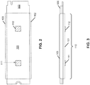
- Figure 2 shows a bottom view and Figure 3 shows a longitudinal side view of the tray device 100 and M.2 module 500 according to one embodiment.
- a riser member is disposed on a bottom surface of baseboard 101.
- the riser member is configured to raise the level of baseboard (i.e., the entry tray device 100) above the motherboard when the M.2 module 500 together with tray device 100 is mounted on the motherboard, which in turn reduces the pressure significantly onto the electronic components disposed on the motherboard and underneath the tray device 100.
- a first riser member 111 is disposed closer to one end of the baseboard 101 while a second riser member 112 is disposed closer to the other end of the baseboard 101.
- the electronic components placed between the tray device 100 and the motherboard would not be pressured or crushed.
- an adhesive layer is also attached to the bottom surface of riser members 111-112. The adhesive layer can reduce the chances of the tray device 100 moving around, for example, laterally with respect to the surface of the motherboard.
- the riser members 111-112 are shown for the illustration purpose only. More or fewer number of riser members may be implemented, and their relative positions on the baseboard 101 can be different.
- a longitudinal dimension or length 110 of baseboard 101 is ranging approximately from 63 - 69 millimeters (mm). In one particular embodiment, the length of baseboard 101 is approximately 63.5 mm. In another particular embodiment, the length of baseboard 101 is approximately 68.5 mm.
- Figure 4 shows a top view and Figure 5 shows a lateral side view of tray device 100 and M.2 module 500 according to one embodiment.
- a lateral dimension or width 115 of tray device 100 is ranging approximately from 24 to 28 mm.
- the width of tray device 100 is approximately 24.5 mm.
- the width of tray device 100 is approximately 27.5 mm.
- the height of tray device 100 is ranging approximately from 4 to 7 mm.
- the height of tray device 100 is approximately 4.2 mm.
- the height of tray device 100 is approximately 7.1 mm.
- tray device 100 As described above, the specific configuration of tray device 100 as shown in Figures 1-5 is described for the purpose of illustration only. Other configurations such as Figures 6A-6E may also be implemented according to other embodiments. As shown in Figures 6C-6E , dependent upon the specific motherboard configuration, there may be a single riser member disposed at the bottom. The riser member may be disposed at any location on the bottom surface of baseboard 101. Referring to Figures 6D and 6E , which show a bottom view and a lateral side view, a single riser member 611 is implemented in this embodiment. In addition, the position of riser member 611 is not at the center of the baseboard. Such a configuration depends upon the available space on the motherboard.
- single riser member 611 may be big enough to support the entire tray device, and located at a proper location within the bottom surface of the baseboard for balancing purpose.
- Multiple adhesive pads 615-616 may be disposed on the bottom of riser member 611.
- certain area such as area 620 at the bottom of the baseboard may be carved out to reserve more room for the electronic components on the motherboard underneath.
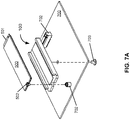
- FIGS 7A-7E show various views of a tray device for retaining an M.2 device according to another embodiment.
- M.2 device 500 can be mounted to via a first end 502 using a screw screwing onto a threaded nut 701 disposed on motherboard 700, while the second end 501 can be inserted into an M.2 compatible socket 702.
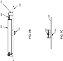
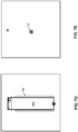
- riser member 111 includes a threaded nut or threaded hole embedded therein to allow a screw 703 to be inserted from a bottom of motherboard 700 to mount tray device 100 onto motherboard as shown in Figure 7B (longitudinal side view), Figure 7C (lateral side view), Figure 7D (top view), and Figure 7E (bottom view).
Landscapes
- Engineering & Computer Science (AREA)
- Theoretical Computer Science (AREA)
- General Engineering & Computer Science (AREA)
- Power Engineering (AREA)
- Human Computer Interaction (AREA)
- Physics & Mathematics (AREA)
- Computer Hardware Design (AREA)
- General Physics & Mathematics (AREA)
- Mechanical Engineering (AREA)
- Microelectronics & Electronic Packaging (AREA)
- Packaging Frangible Articles (AREA)
- Control Of Driving Devices And Active Controlling Of Vehicle (AREA)
- Mounting Components In General For Electric Apparatus (AREA)
Abstract
Description
- Embodiments of the present invention relate generally to M.2 modules used in autonomous driving vehicles. More particularly, embodiments of the invention relate to a tray device to retain an M.2 module to be utilized in an autonomous driving vehicle.
- Vehicles operating in an autonomous mode (e.g., driverless) can relieve occupants, especially the driver, from some driving-related responsibilities. When operating in an autonomous mode, the vehicle can navigate to various locations using onboard sensors, allowing the vehicle to travel with minimal human interaction or in some cases without any passengers.
- Typically, an autonomous driving vehicle (ADV) is controlled by a data processing system that includes various functionalities to perceive a driving environment surrounding the ADV based on sensor data, plan a path to drive the ADV from one point to another point based on the perception information, and to control by issuing proper control commands based on the planning and control data obtained from a variety of sensors (e.g., LIDAR, RADAR, GPS, cameras). Due to the intense computation of the perception, planning, and controlling of autonomous driving, more and more processing resources such as processing and storage modules are deployed within the data processing system.
- One of the popular modules deployed in an ADV is an M.2 compatible device or module. However, when an M.2 module is attached to a motherboard of the data processing system, due to the oscillation during the driving of the vehicle, the M.2 module is easily damaged. There has been a lack of efficient ways to reduce the probability of such damage.
- In an aspect of the disclosure, a tray device to retain an M.2 module used in an autonomous driving vehicle is provided. The tray device includes: a baseboard configured in a relatively rectangular shape having a first and second longitudinal edges and a first and second lateral edges; a first guardrail disposed on a top surface of the baseboard along the first longitudinal edge; a second guardrail disposed on the top surface of the baseboard along the second longitudinal edge, wherein the first and second guardrails are to keep an M.2 module in between and supported by the top surface of the baseboard, while allowing the M.2 module to extend beyond the first and second lateral edges; and a riser member disposed on a bottom surface of the baseboard, wherein when the M.2 module is mounted together with the tray device on a motherboard of a data processing system within an autonomous driving vehicle, the riser member is configured to raise the tray device above the motherboard to prevent the baseboard from applying a heavy pressure on an electronic component mounted on the motherboard and underneath the tray device.
- Embodiments of the invention are illustrated by way of example and not limitation in the figures of the accompanying drawings in which like references indicate similar elements.
-
Figure 1 shows a perspective view of a tray device for retaining an M.2 module according to one embodiment. -
Figure 2 shows a bottom view of a tray device for retaining an M.2 module according to one embodiment. -
Figure 3 shows a longitudinal side view of a tray device for retaining an M.2 module according to one embodiment. -
Figure 4 shows a bottom view of a tray device for retaining an M.2 module according to one embodiment. -
Figure 5 shows a lateral side view of a tray device for retaining an M.2 module according to one embodiment. -
Figures 6A-6E show various views of a tray device for retaining an M.2 device according to alternative embodiments. -
Figures 7A-7E show various views of a tray device for retaining an M.2 device according to alternative embodiments. - Various embodiments and aspects of the inventions will be described with reference to details discussed below, and the accompanying drawings will illustrate the various embodiments. The following description and drawings are illustrative of the invention and are not to be construed as limiting the invention. Numerous specific details are described to provide a thorough understanding of various embodiments of the present invention. However, in certain instances, well-known or conventional details are not described in order to provide a concise discussion of embodiments of the present inventions.
- Reference in the specification to "one embodiment" or "an embodiment" means that a particular feature, structure, or characteristic described in conjunction with the embodiment can be included in at least one embodiment of the invention. The appearances of the phrase "in one embodiment" in various places in the specification do not necessarily all refer to the same embodiment.
- According to some embodiments, before an M.2 compatible module or device is mounted onto a data processing system that operates an ADV, the M.2 module is placed onto a tray device to increase the stiffness of the M.2 module. The tray device containing the M.2 module is then mounted on a board or motherboard of the data processing system. Since the M.2 module is placed on the tray device, the overall stiffness has been significantly increased, which can sustain the physical impact on the M.2 module due to the physical movement and oscillation or vibration during the autonomous driving of the ADV. In addition, the tray device also provides a suspension effect on the M.2 module during the movement of the ADV. As a result, the M.2 module would not be easily damaged during the autonomous driving.
- According to one embodiment, a tray device for retaining an M.2 module includes a baseboard in a relatively rectangular shape, which includes a first and second longitudinal edges or sides and a first and second lateral edges or sides. The tray device further includes a first guardrail (also simply referred to as a guard or guard member) disposed on the top surface of the baseboard along the first longitudinal edge and a second guardrail disposed along the second longitudinal edge. The first and second guardrails are configured to keep the M.2 module in between and supported by the baseboard, while allowing the M.2 module to extend beyond or across the first and second lateral edges, for example, for mounting purposes. The tray device further includes a riser member disposed on the bottom surface of the baseboard (e.g., bottom of the tray device) . When the M.2 module is mounted together with the tray device on a motherboard of a data processing system within an ADV, the riser member is configured to raise the tray device above and away from the motherboard to prevent the baseboard from applying a heavy pressure on an electronic component mounted on the motherboard underneath the tray device, for example, for saving space purpose.
- In one embodiment, before mounting the M.2 module on the motherboard, the M.2 module is placed on the top surface of the baseboard and retained between the first and second guardrails. The M.2 module retained by the tray device is then mounted on the motherboard. As a result, the M.2 module would not be bent due to the physical movement or oscillation/vibration during the autonomous driving of the ADV. In addition, an adhesive strip is placed on the top surface of the baseboard. The adhesive strip is to create an attractive force to draw the M.2 module towards to the top surface of the baseboard. The adhesive strip is utilized to reduce the chances that the M.2 module moves around during the autonomous driving. Further, the adhesive strip may be in a form of a foam pad, which further provides suspension and softens the contacting impact between the M.2 module and the baseboard during the autonomous driving. Furthermore, another adhesive strip may be placed on the bottom of the riser member to reduce the chances that the tray device moves around on the motherboard. Alternatively, the riser member includes a threaded nut or a thread hole molded therein to allow a screw to be inserted from the bottom or opposite side of the motherboard to mount or attach the tray device onto the motherboard.
-
Figure 1 shows a perspective view of a tray device for retaining an M.2 module according to one embodiment. Referring toFigure 1 ,tray device 100 includesbaseboard 101 in a relatively rectangular shape. Baseboard 101 includes a first longitudinal edge (also referred to as a longitudinal side) and a second longitudinal edge such aslongitudinal edge 105, substantially in parallel to each other. Baseboard 101 further includes a first lateral edge (also referred to as a lateral side) and a second lateral edge such aslateral edge 106, substantially in parallel to each other. - A first guardrail 102 (also referred to as a retaining member) is disposed or attached to the first longitudinal edge of
baseboard 101. Asecond guardrail 103 is disposed or attached to the second longitudinal edge ofbaseboard 101.First guardrail 102,second guardrail 103, andbaseboard 101 form a U-shape tray to allow an M.2 module such as M.2module 500 to be retained therein. Note thatfirst guardrail 102,second guardrail 103, andbaseboard 101 may be a single piece of material molded into a U-shape retainer tray.First guardrail 102 andsecond guardrail 103 are configured to retain and restrain M.2module 500 within thetray device 100, while allowing the longitudinal ends of the M.2module 500 extending across or beyond the lateral edges ofbaseboard 101 for the purpose of being mounted on the motherboard of the data processing system. - As shown in
Figure 1 , M.2module 500 includes a firstlongitudinal end 501 and a secondlongitudinal end 502. The firstlongitudinal end 501 includes on the printed circuit board (PCB) an array of electrically conductive pins or pads that can be inserted into an M.2 compatible socket (as shown inFigure 7A ) disposed on the motherboard of the data processing system (e.g., industrial personal computer or IPC) that is utilized to operate an autonomous driving vehicle. Secondlongitudinal end 502 includes a cutout or cavity that allow a screw to be inserted and screwed into a nut or bolt disposed on the motherboard of the data processing system, for example, as shown inFigure 7A . As a result, M.2module 500 can be securely mounted onto the motherboard. - M.2 is a specification for internally mounted computer expansion cards and associated connectors. It replaces the mSATA standard, which uses the PCI Express Mini Card physical card layout and connectors. M.2's more flexible physical specification allows different module widths and lengths, and, paired with the availability of more advanced interfacing features, makes the M.2 more suitable than mSATA for solid-state storage applications in general and particularly for the use in small devices such as ultrabooks or tablets.
- M.2 modules are rectangular, with an edge connector on one side (75 positions with up to 67 pins, 0.5 mm pitch, pins overlap on different sides of the PCB), and a semicircular mounting hole at the center of the opposite edge. An M.2 module is installed into a mating connector provided by the host's circuit board, and a single mounting screw secures the module into place. Components may be mounted on either side of the module, with the actual module type limiting how thick the components can be; the maximum allowable thickness of components is 1.5 mm per side. Different host-side connectors are used for single- and double-sided M.2 modules, providing different amounts of space between the M.2 expansion card and the host's PCB. Circuit boards on the hosts are usually designed to accept multiple lengths of M.2 modules, which means that the sockets capable of accepting longer M.2 modules usually also accept shorter ones by providing different positions for the mounting screw.
- An autonomous vehicle refers to a vehicle that can be configured to in an autonomous mode in which the vehicle navigates through an environment with little or no input from a driver. Such an autonomous vehicle can include a sensor system having one or more sensors that are configured to detect information about the environment in which the vehicle operates. The vehicle and its associated controller(s) use the detected information to navigate through the environment. An autonomous vehicle can operate in a manual mode, a full autonomous mode, or a partial autonomous mode.
- However, referring back to
Figure 1 , due to the relatively thinness of the PCB, M.2module 500 can be easily damaged during the physical movement of the vehicle, especially due to the relative movement between the M.2module 500 and the electronic components mounted on the motherboard beneath the M.2module 500. In one embodiment, by placing M.2module 500 ontotray device 100 before mounting M.2module 500 onto motherboard, the stiffness of the M.2module 500, because thetry device 100 provides protection to M.2module 500 and prevents M.2module 500 from becoming bended. - According to one embodiment, an adhesive strip 104 is disposed on the top surface of
baseboard 101. When M.2module 500 is placed on the top of the adhesive strip 104, the adhesiveness of the adhesive strip 104 creates an attractive force to draw M.2module 500 towards to the top surface ofbaseboard 101, which in turn prevent M.2module 500 from moving around, for example, laterally with respect to the top surface ofbaseboard 101. In one embodiment, the adhesive strip 104 is implemented in an adhesive foam pad. Due to the softness of the foam pad, when M.2module 500 is placed against the top surface ofbaseboard 101 and then mounted onto the motherboard, the foam pad creates a separation force between the M.2module 500 and the top surface of thebaseboard 101 that literally interlocks bothbaseboard 101 and M.2module 500 together. -
Figure 2 shows a bottom view andFigure 3 shows a longitudinal side view of thetray device 100 and M.2module 500 according to one embodiment. Referring toFigures 2 and 3 , in one embodiment, a riser member is disposed on a bottom surface ofbaseboard 101. The riser member is configured to raise the level of baseboard (i.e., the entry tray device 100) above the motherboard when the M.2module 500 together withtray device 100 is mounted on the motherboard, which in turn reduces the pressure significantly onto the electronic components disposed on the motherboard and underneath thetray device 100. - In this embodiment, a
first riser member 111 is disposed closer to one end of thebaseboard 101 while asecond riser member 112 is disposed closer to the other end of thebaseboard 101. With the riser member or members, the electronic components placed between thetray device 100 and the motherboard would not be pressured or crushed. In one embodiment, an adhesive layer is also attached to the bottom surface of riser members 111-112. The adhesive layer can reduce the chances of thetray device 100 moving around, for example, laterally with respect to the surface of the motherboard. Note that the riser members 111-112 are shown for the illustration purpose only. More or fewer number of riser members may be implemented, and their relative positions on thebaseboard 101 can be different. - In one embodiment, a longitudinal dimension or
length 110 of baseboard 101 (e.g., the length of the longitudinal edges 102-103) is ranging approximately from 63 - 69 millimeters (mm). In one particular embodiment, the length ofbaseboard 101 is approximately 63.5 mm. In another particular embodiment, the length ofbaseboard 101 is approximately 68.5 mm. -
Figure 4 shows a top view andFigure 5 shows a lateral side view oftray device 100 and M.2module 500 according to one embodiment. In one embodiment, a lateral dimension orwidth 115 oftray device 100 is ranging approximately from 24 to 28 mm. In one particular embodiment, the width oftray device 100 is approximately 24.5 mm. In another particular embodiment, the width oftray device 100 is approximately 27.5 mm. In one embodiment, the height oftray device 100 is ranging approximately from 4 to 7 mm. In one particular embodiment, the height oftray device 100 is approximately 4.2 mm. In another particular embodiment, the height oftray device 100 is approximately 7.1 mm. - As described above, the specific configuration of
tray device 100 as shown inFigures 1-5 is described for the purpose of illustration only. Other configurations such asFigures 6A-6E may also be implemented according to other embodiments. As shown inFigures 6C-6E , dependent upon the specific motherboard configuration, there may be a single riser member disposed at the bottom. The riser member may be disposed at any location on the bottom surface ofbaseboard 101. Referring toFigures 6D and 6E , which show a bottom view and a lateral side view, asingle riser member 611 is implemented in this embodiment. In addition, the position ofriser member 611 is not at the center of the baseboard. Such a configuration depends upon the available space on the motherboard. The size ofsingle riser member 611 may be big enough to support the entire tray device, and located at a proper location within the bottom surface of the baseboard for balancing purpose. Multiple adhesive pads 615-616 may be disposed on the bottom ofriser member 611. In addition, certain area such asarea 620 at the bottom of the baseboard may be carved out to reserve more room for the electronic components on the motherboard underneath. -
Figures 7A-7E show various views of a tray device for retaining an M.2 device according to another embodiment. Referring toFigure 7A , which shows a perspective view, M.2device 500 can be mounted to via afirst end 502 using a screw screwing onto a threaded nut 701 disposed onmotherboard 700, while thesecond end 501 can be inserted into an M.2compatible socket 702. In addition,riser member 111 includes a threaded nut or threaded hole embedded therein to allow ascrew 703 to be inserted from a bottom ofmotherboard 700 to mounttray device 100 onto motherboard as shown inFigure 7B (longitudinal side view),Figure 7C (lateral side view),Figure 7D (top view), andFigure 7E (bottom view). - In the foregoing specification, embodiments of the invention have been described with reference to specific exemplary embodiments thereof. It will be evident that various modifications may be made thereto without departing from the broader spirit and scope of the invention as set forth in the following claims. The specification and drawings are, accordingly, to be regarded in an illustrative sense rather than a restrictive sense.
Claims (16)
- A tray device to retain an M.2 module used in an autonomous driving vehicle, the tray device comprising:a baseboard configured in a relatively rectangular shape having a first and second longitudinal edges and a first and second lateral edges;a first guardrail disposed on a top surface of the baseboard along the first longitudinal edge;a second guardrail disposed on the top surface of the baseboard along the second longitudinal edge, wherein the first and second guardrails are to keep an M.2 module in between and supported by the top surface of the baseboard, while allowing the M.2 module to extend beyond the first and second lateral edges; anda riser member disposed on a bottom surface of the baseboard, wherein when the M.2 module is mounted together with the tray device on a motherboard of a data processing system within an autonomous driving vehicle, the riser member is configured to raise the tray device above the motherboard to prevent the baseboard from applying a heavy pressure on an electronic component mounted on the motherboard and underneath the tray device.
- The tray device of claim 1, wherein the M.2 module is placed on the top surface of the baseboard between the first guardrail and the second guardrail, before being mounted together with the baseboard on the motherboard of the data processing system,
wherein, the baseboard increases the stiffness of the M.2 module such that the M.2 module will not bend due to oscillation of autonomous driving of the autonomous driving vehicle. - The tray device of claim 1, further comprising an adhesive strip disposed on the top surface of the baseboard, wherein the adhesive strip is to create an attractive force to draw the M.2 module towards to the top surface of the baseboard,
wherein, the adhesive strip is preferably configured in a foam pad to provide additional suspension effect to the M.2 module. - The tray device of claim 1, wherein the riser member further includes an adhesive strip disposed on a bottom surface of the riser member, such that the adhesive strip creates an attractive force to draw the tray device towards to the top surface of the baseboard.
- The tray device of claim 1, wherein the riser member comprises a first riser member disposed closer to a first end of the baseboard and a second riser member disposed closer to a second end of the baseboard.
- The tray device of claim 1, wherein a length of each of the first and second longitudinal edges of the baseboard is ranging approximately 63 to 69 millimeters (mm).
- The tray device of claim 1, wherein a length of each of the first and second longitudinal edges of the baseboard is approximately 63.5 mm.
- The tray device of claim 1, wherein a length of each of the first and second longitudinal edges of the baseboard is approximately 68.5 mm.
- The tray device of claim 1, wherein a width of each of the first and second lateral edges of the baseboard is ranging approximately 24 to 28 mm.
- The tray device of claim 1, wherein a width of each of the first and second lateral edges of the baseboard is approximately 24.5 mm.
- The tray device of claim 1, wherein a width of each of the first and second lateral edges of the baseboard is approximately 27.5 mm.
- The tray device of claim 1, wherein a height of the tray device is ranging approximately from 4 to 7 mm.
- The tray device of claim 1, wherein a height of the tray device is approximately from 4.2 mm.
- The tray device of claim 1, wherein a height of the tray device is approximately from 7.1 mm.
- The tray device of claim 1, wherein the riser further includes a threaded nut embedded therein to allow a screw to be inserted from a bottom of the motherboard to mount the tray device onto the motherboard of the data processing system.
- The tray deice of claim 1, wherein the riser is molded to include a threaded hole embedded therein to allow a screw to be inserted from a bottom of the motherboard to mount the tray device onto the motherboard of the data processing system.
Applications Claiming Priority (1)
| Application Number | Priority Date | Filing Date | Title |
|---|---|---|---|
| US16/102,661 US10474206B1 (en) | 2018-08-13 | 2018-08-13 | Retaining tray for retaining an M.2 compatible device used in autonomous driving vehicles |
Publications (2)
| Publication Number | Publication Date |
|---|---|
| EP3612010A1 true EP3612010A1 (en) | 2020-02-19 |
| EP3612010B1 EP3612010B1 (en) | 2022-05-11 |
Family
ID=66857634
Family Applications (1)
| Application Number | Title | Priority Date | Filing Date |
|---|---|---|---|
| EP19179388.4A Active EP3612010B1 (en) | 2018-08-13 | 2019-06-11 | Retaining tray for retaining an m.2 compatible device used in autonomous driving vehicles |
Country Status (4)
| Country | Link |
|---|---|
| US (1) | US10474206B1 (en) |
| EP (1) | EP3612010B1 (en) |
| JP (1) | JP6799641B2 (en) |
| CN (1) | CN110816434B (en) |
Cited By (1)
| Publication number | Priority date | Publication date | Assignee | Title |
|---|---|---|---|---|
| EP4191378A2 (en) * | 2021-12-03 | 2023-06-07 | Getac Technology Corporation | Electronic device, expansion structure for electronic card and assembly method thereof |
Families Citing this family (1)
| Publication number | Priority date | Publication date | Assignee | Title |
|---|---|---|---|---|
| CN120280713A (en) | 2024-01-08 | 2025-07-08 | 戴尔产品有限公司 | M.2 WLAN module holder |
Citations (3)
| Publication number | Priority date | Publication date | Assignee | Title |
|---|---|---|---|---|
| US20090185356A1 (en) * | 2008-01-21 | 2009-07-23 | Pegatron Corporation | Board assembly |
| US20160165738A1 (en) * | 2014-12-05 | 2016-06-09 | Inventec (Pudong) Technology Corporation | Electronic device and fastening module thereof |
| CN107678508A (en) * | 2017-09-20 | 2018-02-09 | 郑州云海信息技术有限公司 | A kind of M.2 SSD fixed structures |
Family Cites Families (32)
| Publication number | Priority date | Publication date | Assignee | Title |
|---|---|---|---|---|
| US5563770A (en) * | 1994-02-25 | 1996-10-08 | Itt Corporation | IC card with board positioning means |
| JP2708011B2 (en) * | 1995-05-18 | 1998-02-04 | 日本電気株式会社 | Portable information equipment |
| US5590023A (en) * | 1995-07-26 | 1996-12-31 | Dell Usa Lp | Computer apparatus for suspension of computer expansion cards |
| US6362978B1 (en) * | 1999-12-27 | 2002-03-26 | Micron Technology, Inc. | Method and apparatus for biasing a circuit board into engagement with a computer chassis |
| JP3743618B2 (en) * | 2000-10-06 | 2006-02-08 | タイコエレクトロニクスアンプ株式会社 | Card connector assembly |
| US6798669B1 (en) * | 2003-03-05 | 2004-09-28 | Inventec Corporation | Latching structure for motherboards |
| TWM256666U (en) * | 2004-02-04 | 2005-02-01 | Hon Hai Prec Ind Co Ltd | Mounting apparatus for motherboard |
| JP2006066477A (en) * | 2004-08-25 | 2006-03-09 | Hitachi Ltd | Circuit board structure of electronic device |
| US7554812B2 (en) * | 2005-10-11 | 2009-06-30 | Apple Inc. | Structural support for portable electronic devices |
| TWM303514U (en) * | 2006-07-18 | 2006-12-21 | Molex Taiwan Ltd | Buckling structure of card edge connector |
| US20080080147A1 (en) * | 2006-09-28 | 2008-04-03 | Tk Holdings Inc. | Electronic control module |
| US7535731B2 (en) * | 2007-09-21 | 2009-05-19 | Inventec Corporation | Retention device |
| CN201174087Y (en) * | 2008-03-13 | 2008-12-31 | 鸿富锦精密工业(深圳)有限公司 | Motherboard Fixtures |
| US8749967B2 (en) * | 2010-03-17 | 2014-06-10 | PC Partner (Dongguan) Limited | Mounting structure for Mini PCI-E equipment and a computer using the same |
| CN102569684A (en) * | 2010-12-08 | 2012-07-11 | 鸿富锦精密工业(深圳)有限公司 | Battery fixing device |
| TWI423536B (en) * | 2011-07-20 | 2014-01-11 | Wistron Corp | Connector mechanism for connecting a board card |
| CN102981577A (en) * | 2011-09-07 | 2013-03-20 | 鸿富锦精密工业(深圳)有限公司 | Expansion card fixing device |
| US20130216303A1 (en) * | 2012-02-21 | 2013-08-22 | Compupack Technology Co., Ltd | Positioning assembly able to position electrical card |
| CN103365372B (en) * | 2012-04-03 | 2016-12-14 | 泰州市智谷软件园有限公司 | Expansion card fixing device |
| CN103376824B (en) * | 2012-04-23 | 2016-05-18 | 纬创资通股份有限公司 | Storage device assembly module and electronic device |
| CN103974583B (en) * | 2013-02-05 | 2018-03-06 | 鸿富锦精密电子(天津)有限公司 | Electronic installation |
| JP5883420B2 (en) * | 2013-08-26 | 2016-03-15 | 原田工業株式会社 | In-vehicle circuit board holding structure |
| WO2015047299A1 (en) * | 2013-09-27 | 2015-04-02 | Hewlett-Packard Development Company, L.P. | Grips to retain fasteners for expansion cards |
| JP6122372B2 (en) * | 2013-09-27 | 2017-04-26 | 新光電気工業株式会社 | Electronic component case and electronic component device |
| JP6338976B2 (en) * | 2014-08-29 | 2018-06-06 | 株式会社東芝 | Electronic device, mounting member, and mounting method |
| JP6370644B2 (en) * | 2014-08-29 | 2018-08-08 | 株式会社東芝 | Electronic device, mounting member, and mounting method |
| WO2016085493A1 (en) * | 2014-11-26 | 2016-06-02 | Hewlett Packard Enterprise Development Lp | Storage drive carrier module |
| WO2016122594A1 (en) * | 2015-01-30 | 2016-08-04 | Hewlett Packard Enterprise Development Lp | Storage drive riser |
| US9703331B1 (en) * | 2016-05-03 | 2017-07-11 | Dell Products L.P. | Board fastener for securing a data storage device in an information handling system |
| US9778708B1 (en) * | 2016-07-18 | 2017-10-03 | Lenovo Enterprise Solutions (Singapore) Pte. Ltd. | Dual sided latching retainer for computer modules |
| CN106455403A (en) * | 2016-11-30 | 2017-02-22 | 广东欧珀移动通信有限公司 | PCB fixing device |
| JP6792479B2 (en) * | 2017-02-17 | 2020-11-25 | 日本航空電子工業株式会社 | Adapter assembly and equipment |
-
2018
- 2018-08-13 US US16/102,661 patent/US10474206B1/en active Active
-
2019
- 2019-06-11 EP EP19179388.4A patent/EP3612010B1/en active Active
- 2019-06-17 CN CN201910522820.XA patent/CN110816434B/en active Active
- 2019-07-02 JP JP2019123699A patent/JP6799641B2/en not_active Expired - Fee Related
Patent Citations (3)
| Publication number | Priority date | Publication date | Assignee | Title |
|---|---|---|---|---|
| US20090185356A1 (en) * | 2008-01-21 | 2009-07-23 | Pegatron Corporation | Board assembly |
| US20160165738A1 (en) * | 2014-12-05 | 2016-06-09 | Inventec (Pudong) Technology Corporation | Electronic device and fastening module thereof |
| CN107678508A (en) * | 2017-09-20 | 2018-02-09 | 郑州云海信息技术有限公司 | A kind of M.2 SSD fixed structures |
Non-Patent Citations (1)
| Title |
|---|
| IAN CUTRESS: "ASUS X99 Launch: Rampage V Extreme, X99-Deluxe, X99-A and X99-Pro", 29 August 2014 (2014-08-29), XP055489225, Retrieved from the Internet <URL:https://www.anandtech.com/show/8449/asus-x99-launch-rampage-v-extreme-x99deluxe-x99a-and-x99pro> [retrieved on 20180629] * |
Cited By (1)
| Publication number | Priority date | Publication date | Assignee | Title |
|---|---|---|---|---|
| EP4191378A2 (en) * | 2021-12-03 | 2023-06-07 | Getac Technology Corporation | Electronic device, expansion structure for electronic card and assembly method thereof |
Also Published As
| Publication number | Publication date |
|---|---|
| US10474206B1 (en) | 2019-11-12 |
| JP6799641B2 (en) | 2020-12-16 |
| CN110816434A (en) | 2020-02-21 |
| EP3612010B1 (en) | 2022-05-11 |
| JP2020036000A (en) | 2020-03-05 |
| CN110816434B (en) | 2023-03-14 |
Similar Documents
| Publication | Publication Date | Title |
|---|---|---|
| US9155231B2 (en) | Motor-drive unit having heat radiator | |
| US20020044416A1 (en) | Micro hard drive caddy | |
| EP3612010B1 (en) | Retaining tray for retaining an m.2 compatible device used in autonomous driving vehicles | |
| CN110580111A (en) | Display device and method of manufacturing electronic device using display device | |
| US11034128B2 (en) | Protection tape for printed circuit board and display device including the same | |
| US12265432B2 (en) | Portable solid-state drive module | |
| CN114093243B (en) | Display module and preparation method thereof | |
| EP2821693B1 (en) | Lighting device | |
| US9136621B1 (en) | Guides and tab arrangement to retain a card having an edge connector and method of use | |
| US10120824B2 (en) | Bridge board with structure for preventing solid state drive module bending and data storage device including the same | |
| US8282406B2 (en) | Connector with electrostatic discharge protection | |
| CN113257114B (en) | Display device and electronic apparatus | |
| US7140547B2 (en) | Data storage configuration having a display device | |
| US8969739B2 (en) | Semiconductor device | |
| JP2014011910A (en) | Wiring member and on-vehicle electronic unit | |
| CN203456662U (en) | Tray plate for installing printed circuit board and system containing the same | |
| US20190103689A1 (en) | Memory device | |
| JP2007193410A (en) | Information processing device | |
| CN110335541B (en) | Display panel and display device | |
| US10993324B2 (en) | Computer system with modified module socket | |
| JP6384311B2 (en) | Display device | |
| KR102960844B1 (en) | Laminate device | |
| KR20200143586A (en) | Supporter for electrical component | |
| KR20140116693A (en) | Flexible printed circuit board | |
| CN114743464A (en) | Driving module and display device |
Legal Events
| Date | Code | Title | Description |
|---|---|---|---|
| PUAI | Public reference made under article 153(3) epc to a published international application that has entered the european phase |
Free format text: ORIGINAL CODE: 0009012 |
|
| STAA | Information on the status of an ep patent application or granted ep patent |
Free format text: STATUS: THE APPLICATION HAS BEEN PUBLISHED |
|
| AK | Designated contracting states |
Kind code of ref document: A1 Designated state(s): AL AT BE BG CH CY CZ DE DK EE ES FI FR GB GR HR HU IE IS IT LI LT LU LV MC MK MT NL NO PL PT RO RS SE SI SK SM TR |
|
| AX | Request for extension of the european patent |
Extension state: BA ME |
|
| STAA | Information on the status of an ep patent application or granted ep patent |
Free format text: STATUS: REQUEST FOR EXAMINATION WAS MADE |
|
| 17P | Request for examination filed |
Effective date: 20200818 |
|
| RBV | Designated contracting states (corrected) |
Designated state(s): AL AT BE BG CH CY CZ DE DK EE ES FI FR GB GR HR HU IE IS IT LI LT LU LV MC MK MT NL NO PL PT RO RS SE SI SK SM TR |
|
| GRAP | Despatch of communication of intention to grant a patent |
Free format text: ORIGINAL CODE: EPIDOSNIGR1 |
|
| STAA | Information on the status of an ep patent application or granted ep patent |
Free format text: STATUS: GRANT OF PATENT IS INTENDED |
|
| RIC1 | Information provided on ipc code assigned before grant |
Ipc: G06F 1/18 20060101ALI20211216BHEP Ipc: H05K 7/14 20060101AFI20211216BHEP |
|
| INTG | Intention to grant announced |
Effective date: 20220107 |
|
| GRAS | Grant fee paid |
Free format text: ORIGINAL CODE: EPIDOSNIGR3 |
|
| GRAA | (expected) grant |
Free format text: ORIGINAL CODE: 0009210 |
|
| STAA | Information on the status of an ep patent application or granted ep patent |
Free format text: STATUS: THE PATENT HAS BEEN GRANTED |
|
| AK | Designated contracting states |
Kind code of ref document: B1 Designated state(s): AL AT BE BG CH CY CZ DE DK EE ES FI FR GB GR HR HU IE IS IT LI LT LU LV MC MK MT NL NO PL PT RO RS SE SI SK SM TR |
|
| REG | Reference to a national code |
Ref country code: GB Ref legal event code: FG4D |
|
| REG | Reference to a national code |
Ref country code: CH Ref legal event code: EP |
|
| REG | Reference to a national code |
Ref country code: AT Ref legal event code: REF Ref document number: 1492624 Country of ref document: AT Kind code of ref document: T Effective date: 20220515 |
|
| REG | Reference to a national code |
Ref country code: DE Ref legal event code: R096 Ref document number: 602019014757 Country of ref document: DE |
|
| REG | Reference to a national code |
Ref country code: IE Ref legal event code: FG4D |
|
| REG | Reference to a national code |
Ref country code: LT Ref legal event code: MG9D |
|
| REG | Reference to a national code |
Ref country code: NL Ref legal event code: MP Effective date: 20220511 |
|
| REG | Reference to a national code |
Ref country code: AT Ref legal event code: MK05 Ref document number: 1492624 Country of ref document: AT Kind code of ref document: T Effective date: 20220511 |
|
| PG25 | Lapsed in a contracting state [announced via postgrant information from national office to epo] |
Ref country code: SE Free format text: LAPSE BECAUSE OF FAILURE TO SUBMIT A TRANSLATION OF THE DESCRIPTION OR TO PAY THE FEE WITHIN THE PRESCRIBED TIME-LIMIT Effective date: 20220511 Ref country code: PT Free format text: LAPSE BECAUSE OF FAILURE TO SUBMIT A TRANSLATION OF THE DESCRIPTION OR TO PAY THE FEE WITHIN THE PRESCRIBED TIME-LIMIT Effective date: 20220912 Ref country code: NO Free format text: LAPSE BECAUSE OF FAILURE TO SUBMIT A TRANSLATION OF THE DESCRIPTION OR TO PAY THE FEE WITHIN THE PRESCRIBED TIME-LIMIT Effective date: 20220811 Ref country code: NL Free format text: LAPSE BECAUSE OF FAILURE TO SUBMIT A TRANSLATION OF THE DESCRIPTION OR TO PAY THE FEE WITHIN THE PRESCRIBED TIME-LIMIT Effective date: 20220511 Ref country code: LT Free format text: LAPSE BECAUSE OF FAILURE TO SUBMIT A TRANSLATION OF THE DESCRIPTION OR TO PAY THE FEE WITHIN THE PRESCRIBED TIME-LIMIT Effective date: 20220511 Ref country code: HR Free format text: LAPSE BECAUSE OF FAILURE TO SUBMIT A TRANSLATION OF THE DESCRIPTION OR TO PAY THE FEE WITHIN THE PRESCRIBED TIME-LIMIT Effective date: 20220511 Ref country code: GR Free format text: LAPSE BECAUSE OF FAILURE TO SUBMIT A TRANSLATION OF THE DESCRIPTION OR TO PAY THE FEE WITHIN THE PRESCRIBED TIME-LIMIT Effective date: 20220812 Ref country code: FI Free format text: LAPSE BECAUSE OF FAILURE TO SUBMIT A TRANSLATION OF THE DESCRIPTION OR TO PAY THE FEE WITHIN THE PRESCRIBED TIME-LIMIT Effective date: 20220511 Ref country code: ES Free format text: LAPSE BECAUSE OF FAILURE TO SUBMIT A TRANSLATION OF THE DESCRIPTION OR TO PAY THE FEE WITHIN THE PRESCRIBED TIME-LIMIT Effective date: 20220511 Ref country code: BG Free format text: LAPSE BECAUSE OF FAILURE TO SUBMIT A TRANSLATION OF THE DESCRIPTION OR TO PAY THE FEE WITHIN THE PRESCRIBED TIME-LIMIT Effective date: 20220811 Ref country code: AT Free format text: LAPSE BECAUSE OF FAILURE TO SUBMIT A TRANSLATION OF THE DESCRIPTION OR TO PAY THE FEE WITHIN THE PRESCRIBED TIME-LIMIT Effective date: 20220511 |
|
| PG25 | Lapsed in a contracting state [announced via postgrant information from national office to epo] |
Ref country code: RS Free format text: LAPSE BECAUSE OF FAILURE TO SUBMIT A TRANSLATION OF THE DESCRIPTION OR TO PAY THE FEE WITHIN THE PRESCRIBED TIME-LIMIT Effective date: 20220511 Ref country code: PL Free format text: LAPSE BECAUSE OF FAILURE TO SUBMIT A TRANSLATION OF THE DESCRIPTION OR TO PAY THE FEE WITHIN THE PRESCRIBED TIME-LIMIT Effective date: 20220511 Ref country code: LV Free format text: LAPSE BECAUSE OF FAILURE TO SUBMIT A TRANSLATION OF THE DESCRIPTION OR TO PAY THE FEE WITHIN THE PRESCRIBED TIME-LIMIT Effective date: 20220511 Ref country code: IS Free format text: LAPSE BECAUSE OF FAILURE TO SUBMIT A TRANSLATION OF THE DESCRIPTION OR TO PAY THE FEE WITHIN THE PRESCRIBED TIME-LIMIT Effective date: 20220911 |
|
| PG25 | Lapsed in a contracting state [announced via postgrant information from national office to epo] |
Ref country code: SM Free format text: LAPSE BECAUSE OF FAILURE TO SUBMIT A TRANSLATION OF THE DESCRIPTION OR TO PAY THE FEE WITHIN THE PRESCRIBED TIME-LIMIT Effective date: 20220511 Ref country code: SK Free format text: LAPSE BECAUSE OF FAILURE TO SUBMIT A TRANSLATION OF THE DESCRIPTION OR TO PAY THE FEE WITHIN THE PRESCRIBED TIME-LIMIT Effective date: 20220511 Ref country code: RO Free format text: LAPSE BECAUSE OF FAILURE TO SUBMIT A TRANSLATION OF THE DESCRIPTION OR TO PAY THE FEE WITHIN THE PRESCRIBED TIME-LIMIT Effective date: 20220511 Ref country code: EE Free format text: LAPSE BECAUSE OF FAILURE TO SUBMIT A TRANSLATION OF THE DESCRIPTION OR TO PAY THE FEE WITHIN THE PRESCRIBED TIME-LIMIT Effective date: 20220511 Ref country code: DK Free format text: LAPSE BECAUSE OF FAILURE TO SUBMIT A TRANSLATION OF THE DESCRIPTION OR TO PAY THE FEE WITHIN THE PRESCRIBED TIME-LIMIT Effective date: 20220511 Ref country code: CZ Free format text: LAPSE BECAUSE OF FAILURE TO SUBMIT A TRANSLATION OF THE DESCRIPTION OR TO PAY THE FEE WITHIN THE PRESCRIBED TIME-LIMIT Effective date: 20220511 |
|
| REG | Reference to a national code |
Ref country code: CH Ref legal event code: PL |
|
| REG | Reference to a national code |
Ref country code: DE Ref legal event code: R097 Ref document number: 602019014757 Country of ref document: DE |
|
| REG | Reference to a national code |
Ref country code: BE Ref legal event code: MM Effective date: 20220630 |
|
| PG25 | Lapsed in a contracting state [announced via postgrant information from national office to epo] |
Ref country code: MC Free format text: LAPSE BECAUSE OF FAILURE TO SUBMIT A TRANSLATION OF THE DESCRIPTION OR TO PAY THE FEE WITHIN THE PRESCRIBED TIME-LIMIT Effective date: 20220511 |
|
| PLBE | No opposition filed within time limit |
Free format text: ORIGINAL CODE: 0009261 |
|
| STAA | Information on the status of an ep patent application or granted ep patent |
Free format text: STATUS: NO OPPOSITION FILED WITHIN TIME LIMIT |
|
| PG25 | Lapsed in a contracting state [announced via postgrant information from national office to epo] |
Ref country code: AL Free format text: LAPSE BECAUSE OF FAILURE TO SUBMIT A TRANSLATION OF THE DESCRIPTION OR TO PAY THE FEE WITHIN THE PRESCRIBED TIME-LIMIT Effective date: 20220511 |
|
| 26N | No opposition filed |
Effective date: 20230214 |
|
| PG25 | Lapsed in a contracting state [announced via postgrant information from national office to epo] |
Ref country code: LU Free format text: LAPSE BECAUSE OF NON-PAYMENT OF DUE FEES Effective date: 20220611 Ref country code: LI Free format text: LAPSE BECAUSE OF NON-PAYMENT OF DUE FEES Effective date: 20220630 Ref country code: IE Free format text: LAPSE BECAUSE OF NON-PAYMENT OF DUE FEES Effective date: 20220611 Ref country code: CH Free format text: LAPSE BECAUSE OF NON-PAYMENT OF DUE FEES Effective date: 20220630 |
|
| PG25 | Lapsed in a contracting state [announced via postgrant information from national office to epo] |
Ref country code: SI Free format text: LAPSE BECAUSE OF FAILURE TO SUBMIT A TRANSLATION OF THE DESCRIPTION OR TO PAY THE FEE WITHIN THE PRESCRIBED TIME-LIMIT Effective date: 20220511 Ref country code: BE Free format text: LAPSE BECAUSE OF NON-PAYMENT OF DUE FEES Effective date: 20220630 |
|
| P01 | Opt-out of the competence of the unified patent court (upc) registered |
Effective date: 20230526 |
|
| PGFP | Annual fee paid to national office [announced via postgrant information from national office to epo] |
Ref country code: FR Payment date: 20230523 Year of fee payment: 5 |
|
| PGFP | Annual fee paid to national office [announced via postgrant information from national office to epo] |
Ref country code: GB Payment date: 20230511 Year of fee payment: 5 |
|
| PG25 | Lapsed in a contracting state [announced via postgrant information from national office to epo] |
Ref country code: IT Free format text: LAPSE BECAUSE OF FAILURE TO SUBMIT A TRANSLATION OF THE DESCRIPTION OR TO PAY THE FEE WITHIN THE PRESCRIBED TIME-LIMIT Effective date: 20220511 |
|
| PG25 | Lapsed in a contracting state [announced via postgrant information from national office to epo] |
Ref country code: MK Free format text: LAPSE BECAUSE OF FAILURE TO SUBMIT A TRANSLATION OF THE DESCRIPTION OR TO PAY THE FEE WITHIN THE PRESCRIBED TIME-LIMIT Effective date: 20220511 Ref country code: CY Free format text: LAPSE BECAUSE OF FAILURE TO SUBMIT A TRANSLATION OF THE DESCRIPTION OR TO PAY THE FEE WITHIN THE PRESCRIBED TIME-LIMIT Effective date: 20220511 |
|
| PG25 | Lapsed in a contracting state [announced via postgrant information from national office to epo] |
Ref country code: HU Free format text: LAPSE BECAUSE OF FAILURE TO SUBMIT A TRANSLATION OF THE DESCRIPTION OR TO PAY THE FEE WITHIN THE PRESCRIBED TIME-LIMIT; INVALID AB INITIO Effective date: 20190611 |
|
| PG25 | Lapsed in a contracting state [announced via postgrant information from national office to epo] |
Ref country code: MT Free format text: LAPSE BECAUSE OF FAILURE TO SUBMIT A TRANSLATION OF THE DESCRIPTION OR TO PAY THE FEE WITHIN THE PRESCRIBED TIME-LIMIT Effective date: 20220511 |
|
| PG25 | Lapsed in a contracting state [announced via postgrant information from national office to epo] |
Ref country code: BG Free format text: LAPSE BECAUSE OF FAILURE TO SUBMIT A TRANSLATION OF THE DESCRIPTION OR TO PAY THE FEE WITHIN THE PRESCRIBED TIME-LIMIT Effective date: 20220511 |
|
| PG25 | Lapsed in a contracting state [announced via postgrant information from national office to epo] |
Ref country code: BG Free format text: LAPSE BECAUSE OF FAILURE TO SUBMIT A TRANSLATION OF THE DESCRIPTION OR TO PAY THE FEE WITHIN THE PRESCRIBED TIME-LIMIT Effective date: 20220511 |
|
| GBPC | Gb: european patent ceased through non-payment of renewal fee |
Effective date: 20240611 |
|
| PG25 | Lapsed in a contracting state [announced via postgrant information from national office to epo] |
Ref country code: FR Free format text: LAPSE BECAUSE OF NON-PAYMENT OF DUE FEES Effective date: 20240630 |
|
| PG25 | Lapsed in a contracting state [announced via postgrant information from national office to epo] |
Ref country code: GB Free format text: LAPSE BECAUSE OF NON-PAYMENT OF DUE FEES Effective date: 20240611 |
|
| PGFP | Annual fee paid to national office [announced via postgrant information from national office to epo] |
Ref country code: DE Payment date: 20250618 Year of fee payment: 7 |
|
| PG25 | Lapsed in a contracting state [announced via postgrant information from national office to epo] |
Ref country code: TR Free format text: LAPSE BECAUSE OF FAILURE TO SUBMIT A TRANSLATION OF THE DESCRIPTION OR TO PAY THE FEE WITHIN THE PRESCRIBED TIME-LIMIT Effective date: 20220511 |