EP3611891A1 - Signal processing device and method - Google Patents
Signal processing device and method Download PDFInfo
- Publication number
- EP3611891A1 EP3611891A1 EP18783726.5A EP18783726A EP3611891A1 EP 3611891 A1 EP3611891 A1 EP 3611891A1 EP 18783726 A EP18783726 A EP 18783726A EP 3611891 A1 EP3611891 A1 EP 3611891A1
- Authority
- EP
- European Patent Office
- Prior art keywords
- unit
- signal
- frequency
- received signal
- processing apparatus
- Prior art date
- Legal status (The legal status is an assumption and is not a legal conclusion. Google has not performed a legal analysis and makes no representation as to the accuracy of the status listed.)
- Granted
Links
Images























Classifications
-
- H—ELECTRICITY
- H04—ELECTRIC COMMUNICATION TECHNIQUE
- H04L—TRANSMISSION OF DIGITAL INFORMATION, e.g. TELEGRAPHIC COMMUNICATION
- H04L27/00—Modulated-carrier systems
- H04L27/26—Systems using multi-frequency codes
-
- H—ELECTRICITY
- H04—ELECTRIC COMMUNICATION TECHNIQUE
- H04B—TRANSMISSION
- H04B1/00—Details of transmission systems, not covered by a single one of groups H04B3/00 - H04B13/00; Details of transmission systems not characterised by the medium used for transmission
- H04B1/06—Receivers
- H04B1/10—Means associated with receiver for limiting or suppressing noise or interference
-
- H—ELECTRICITY
- H04—ELECTRIC COMMUNICATION TECHNIQUE
- H04L—TRANSMISSION OF DIGITAL INFORMATION, e.g. TELEGRAPHIC COMMUNICATION
- H04L27/00—Modulated-carrier systems
- H04L27/0014—Carrier regulation
-
- H—ELECTRICITY
- H04—ELECTRIC COMMUNICATION TECHNIQUE
- H04L—TRANSMISSION OF DIGITAL INFORMATION, e.g. TELEGRAPHIC COMMUNICATION
- H04L27/00—Modulated-carrier systems
- H04L27/18—Phase-modulated carrier systems, i.e. using phase-shift keying
- H04L27/22—Demodulator circuits; Receiver circuits
- H04L27/227—Demodulator circuits; Receiver circuits using coherent demodulation
- H04L27/2271—Demodulator circuits; Receiver circuits using coherent demodulation wherein the carrier recovery circuit uses only the demodulated signals
Definitions
- the present technology relates to signal processing apparatus and method, and particularly, to signal processing apparatus and method that can reduce deterioration in reception sensitivity.
- the present disclosure has been made in view of such a situation, and enables high sensitivity detection by performing phase detection properly even for a received signal with a low SNR.
- a signal processing apparatus is a signal processing apparatus including a correction unit that corrects a received signal using channel information obtained from a plurality of frequency samples being significant components that are extracted from frequency samples of known information included in the received signal.
- the correction unit can correct a phase of the received signal.
- the correction unit can correct an amplitude of the received signal.
- the correction unit can correct the received signal using channel information obtained by performing inverse Fourier transform on the plurality of frequency samples being the significant components.
- the correction unit can correct the received signal using channel information obtained by combining an oscillation signal with frequency and amplitude of each of the plurality of frequency samples being the significant components.
- the correction unit can correct the received signal using channel information obtained from a peak sample that is a frequency sample with an amplitude larger than that of surroundings and a neighboring sample that is a frequency sample around the peak sample.
- the neighboring sample can be a frequency sample on each of both sides of the peak sample.
- the correction unit can correct the received signal using channel information obtained from a plurality of the peak samples and the neighboring sample for each of the peak samples.
- the correction unit can correct the received signal using channel information obtained from a predetermined number of the peak samples selected in descending order of amplitude, and the neighboring sample for each of the peak samples.
- correction units can be further included a plurality of the correction units and a combining unit that combines correction results of the correction units, in which the correction units can be configured to correct the received signal using peak samples different from one another and a neighboring sample for the peak samples.
- the received signal can have the known information regularly inserted between unknown information.
- the received signal can have a configuration in which a frame of a predetermined length is repeated with data in units of symbols being arranged in each frame.
- the received signal can have a symbol of a synchronization signal, which is known, inserted between symbols of the data that is unknown in each frame.
- the received signal can have a configuration in which one symbol of the data that is unknown and one symbol of the synchronization signal that is known are alternately arranged.
- the received signal can have a configuration in which two symbols of the data that is unknown and one symbol of the synchronization signal that is known are alternately arranged.
- a guard bit including an unnecessary symbol can be attached at both ends of each frame of the received signal.
- a separation unit that separates a symbol of data being unknown and a symbol of a synchronization signal being known that are included in the received signal
- a generation unit that generates channel information from the symbol of the synchronization signal being known that is separated from the data being unknown by the separation unit
- a transform unit that transforms the channel information generated by the generation unit into frequency samples
- an extraction unit that extracts a plurality of frequency samples as significant components from the frequency samples transformed by the transform unit
- an inverse transform unit that inversely transforms the plurality of frequency samples as the significant components extracted by the extraction unit into channel information.
- a frame synchronization unit that achieves synchronization in units of frames of the received signal using the frequency samples transformed by the transform unit.
- an integration unit that integrates the received signal corrected by the correction unit.
- a signal processing method is a signal processing method that corrects a received signal using channel information obtained from a plurality of frequency samples being significant components that are extracted from frequency samples of known information included in the received signal.
- Signal processing apparatus and method correct a received signal using channel information obtained from a plurality of frequency samples being significant components that are extracted from frequency samples of known information included in the received signal.
- signals can be processed. Moreover, according to the present technology, deterioration in reception sensitivity can be reduced.
- Patent Documents 1 and 2 for example, in order for an orthogonal frequency division multiplexing (OFDM) system or the like to reduce deterioration in reception sensitivity due to a frequency deviation of a received signal, there has been a method of correcting the phase of the received signal by controlling, on a receiving side, an oscillation frequency of a variable frequency oscillator by a phase locked loop (PLL).
- PLL phase locked loop
- a receiver detects a phase shift in a received signal and feeds back the phase difference to correct the phase of the received signal. As a result, the frequency deviation of the received signal is corrected, and deterioration in the reception sensitivity due to the frequency deviation is reduced.
- JP 2016-46618 A discloses a system for transmitting information regarding a sensor or the like by using, for example, radio waves in the 920 Mz band as a technology for implementing long-range wireless communication.
- a transmit signal is transmitted in frames of approximately 0.2 seconds, as illustrated in Fig. 3 .
- the same frame can be repeatedly transmitted a plurality of times as well.
- One frame includes data of approximately 9600 symbols.
- One frame includes data of information to be transmitted (information unknown to a receiving side) and a synchronization signal (information known to the receiving side).
- one frame includes 4800 symbols of the data and 4800 symbols of the synchronization signal.
- the symbol of the data and the symbol of the synchronization signal are alternately transmitted.
- Such a transmit signal is modulated by, for example, ⁇ /2 shift binary phase shift keying (BPSK) and transmitted.
- BPSK binary phase shift keying
- the use of this system can set the maximum continuous transmission time to be short and perform transmission by selecting a channel from a large number of frequency channels, so that a transmission/reception system that is stronger against interference can be built. Furthermore, by integrating many short-time frames, an effective SNR can be improved without exceeding the limit of the maximum transmission time defined in the Radio Law. At this time, the synchronization signals are distributed throughout the frame so that the phase and frequency can be corrected more appropriately even in a case where a phase fluctuation occurs in the frame. As a result of these, for example, even a weak received signal that is buried in noise and difficult to decode by a conventional method can be decoded more properly. That is, the reception sensitivity is improved so that longer-range wireless communication can be implemented.
- a high sensitivity receiver receiving such a transmit signal can improve data reception sensitivity by detecting a known synchronization signal.
- the high sensitivity receiver synchronizes frames, symbols, and carriers, for example.
- the frames are synchronized in about 0.2 seconds.
- the symbols are synchronized in about 20 micro ( ⁇ ) seconds.
- the carriers are synchronized in about 1 nano (n) second.
- the carrier synchronization requires the highest accuracy.
- the high sensitivity receiver can detect a phase change ⁇ (t) of each frame as illustrated in Fig. 4 . If the phase change ⁇ (t) can be detected, the received signal can be corrected with e j ⁇ (t) and then combined and decoded. However, in a case where the SNR is low, the received signal is buried in noise so that the phase change ⁇ (t) cannot be observed.
- a possible configuration of the high sensitivity receiver capable of dealing with such a low SNR is to detect a frequency deviation f ⁇ .
- the received signal in each frame can be corrected with a phase line of 2 ⁇ f ⁇ t as illustrated in Fig. 5 .
- This method approximates the phase change ⁇ (t) by a straight line and thus results in a phase error, thereby having had a disadvantage that high sensitivity to be obtained originally is impaired.
- the high sensitivity receiver uses a global navigation satellite system (GNSS) signal transmitted from a GNSS satellite as illustrated in Fig. 6 .
- GNSS global navigation satellite system
- the GNSS is a system for acquiring location and time information using wireless signals obtained from satellites around the Earth, and is launched by the United States, Russia, China, Europe, and the like and generally called a global positioning system (GPS) in some cases.
- GPS global positioning system
- the GNSS satellite has a cesium oscillator with high accuracy, and can obtain time information more accurately than an oscillator usually built in a receiver or the like. By correcting the carrier frequency using such time information, the center of the transmit frequency and the received frequency can be corrected with an accuracy of about ⁇ 10 Hz.
- the frequency deviation of the received signal occurs due to various factors.
- a frequency shift Doppler shift
- a frequency shift In a case where the transmitter moves relative to a receiver at a relative speed of about 100 kilometers per hour, for example, a frequency shift of about 86 Hz possibly occurs in a transmit signal transmitted from the transmitter.
- This Doppler shift is determined by the relative speed of movement of the transmitter as viewed from the receiver and thus takes a different value depending on the direction of movement of the transmitter.
- the frequency correction can be performed using the GNSS signal, the accuracy of such correction is limited and cannot achieve the required accuracy of about ⁇ 0.2 Hz.
- the receiver is required to perform the phase correction of the received signal with higher accuracy.
- the system is characterized by high sensitivity detection in a low SNR environment and is largely affected by deterioration in the reception sensitivity due to the frequency deviation, so that more accurate phase correction is required.
- the transmit data is transmitted in frames of about 0.2 seconds.
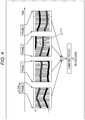
- Each frame includes 9600 symbols of information where, for example, each of 4800 symbols of data (information unknown to the receiving side) and each of 4800 symbols of the synchronization signal (information known to the receiving side) are alternately arranged as illustrated in Fig. 8 .
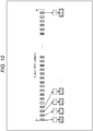
- the high sensitivity receiver Upon receiving such a signal, the high sensitivity receiver extracts the synchronization signals from the received signal (IQ signal) as illustrated in Fig. 9 . Then, as illustrated in Fig. 10 , the high sensitivity receiver multiplies the synchronization signals by known data (+1 or -1) and generates channel information samples (p (k) (0 ⁇ k ⁇ (N - 1))). In a case where synchronization is achieved, the channel information samples (p (k)) are all +1 (at one point on a real axis) as illustrated in Fig. 11 (a value to give such a result is multiplied). However, if the received signal has a frequency deviation, the channel information samples (p (k)) are not all +1 (on the real axis), but the phase rotates with time as illustrated in Fig. 12 .
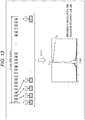
- the high sensitivity receiver performs a Fourier transform on the channel information samples (p (k)) to find frequency components and obtains a frequency distribution C (f) as in a graph at the bottom of Fig. 13 .
- the signal components are concentrated at a specific frequency. That is, the frequency of the signal is shifted by the frequency at which the maximum spectrum is obtained on this graph. Therefore, the frequency deviation can be reduced by performing the phase correction with f ⁇ being the frequency at which the maximum spectrum is obtained.
- the frequency (f ⁇ ) at which the maximum spectrum is obtained needs to be identified with the accuracy of about ⁇ 0.2 Hz.
- the frequency resolution is 5 Hz. That is, there has been a problem that the accuracy is not sufficient to correct the frequency deviation.
- the phase ⁇ (t) of the signal in each frame changes in a relatively gentle curve as illustrated in Fig. 14 .
- the received signal can be expressed as e j2 ⁇ fdt + j ⁇ (t) . That is, the received signal e j2 ⁇ fdt + j ⁇ (t) can be regarded as having a waveform obtained by gently modulating the phase of a single carrier of the frequency fd (Hz) by ⁇ (t).
- the Fourier transform (fast Fourier transform (FFT)) can be performed on a frame-by-frame basis assuming that the received signal for one frame is repeated indefinitely as illustrated in Fig. 16 .
- FFT fast Fourier transform
- the aforementioned frequency distribution is obtained as an impulse train in 5 Hz increments as illustrated in Fig. 17 .
- the spectrum distribution (hill-shaped distribution) of the received signal can be more accurately reproduced by the spectra of the peak and its neighboring points.
- the received signal e j2 ⁇ fdt + j ⁇ (t) can be expressed as in expression (1) below.
- a 0 , A 1 , and A 2 are complex amplitudes typically represented by complex numbers. That is, the phase correction can be performed with high accuracy by performing the phase correction using a plurality of frequency samples. Therefore, deterioration in the reception sensitivity due to the frequency deviation can be reduced.
- a result of combining the complex amplitudes A 0 , A 1 , and A 2 of the three different frequencies also represents a gentle amplitude fluctuation. The use of this amplitude fluctuation can correct not only the phase but also the amplitude fluctuation. As a result, more accurate correction can be performed to be able to reduce deterioration in the reception sensitivity.
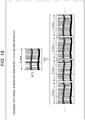
- FIG. 19 is a diagram illustrating an example of the main configuration of a location notification system which is an embodiment of a signal transmission/reception system to which the present technology is applied.
- a location notification system 100 illustrated in Fig. 19 is a system in which a transmission device 101 notifies its own location. This system is used, for example, for monitoring and managing the location of a target.
- the location notification system 100 includes devices such as the transmission device 101, a high sensitivity reception device 102, a server 104, and a terminal device 105.
- the number of each of the transmission devices 101, the high sensitivity reception devices 102, the servers 104, and the terminal devices 105 is arbitrary, and may be plural.
- the transmission device 101 is an embodiment of a transmission device to which the present technology is applied and transmits, for example, identification information for identifying itself, location information indicating its own location, and the like as a wireless signal.
- the high sensitivity reception device 102 is an embodiment of a reception device to which the present technology is applied and receives the wireless signal to acquire the identification information, the location information, and the like of the transmission device 101 and supply them to the server 104 via a network 103. That is, the high sensitivity reception device 102 functions as a relay station that relays the information transmitted from the transmission device 101 and transmits the information to the server 104.
- the server 104 manages the location of each transmission device 101 by managing the identification information in association with the location information.
- the terminal device 105 operated by a user who wants to know the location of the transmission device 101 accesses the server 104 via the network 103, supplies identification information of a desired transmission device 101, and requests location information thereof.
- the server 104 supplies the terminal device 105 with the requested location information corresponding to the identification information.
- the terminal device 105 acquires the location information and displays the location information along with map data or the like, for example, thereby notifying the user of the location of the transmission device 101.
- the server 104 can indirectly manage the location of a target whose location is to be monitored (managed) by causing the location monitoring (management) target to carry (including possessing, wearing, and the like) such transmission device 101.
- the user has an elderly person 111 as the target whose location is to be monitored and causes the elderly person 111 to carry the transmission device 101.
- the location of the transmission device 101 is managed by the server 104 and provided to the terminal device 105. The user can thus operate the terminal device 105 and grasp the location of the elderly person 111 carrying the transmission device 101.
- the target whose location is to be monitored is arbitrary.
- the target may be a child, an animal such as a dog or a cat, or an employee or the like of a company.
- the transmission device 101 may be configured as a dedicated device or may be incorporated into a portable information processing apparatus such as a mobile phone or a smart phone, for example.
- the location information of the transmission device 101 may be any information indicating the location of the transmission device 101, and may be generated in any manner.
- the transmission device 101 may receive a global navigation satellite system (GNSS) signal from a GNSS satellite and obtain its own location information (for example, latitude and longitude) on the basis of the GNSS signal.
- GNSS global navigation satellite system
- the transmission device 101 may identify its own location using a dedicated location identification system other than the GNSS.
- the location information may be generated in a device other than the transmission device 101 such as the high sensitivity reception device 102, the server 104, or a dedicated information processing apparatus (server or the like) provided separately, for example.
- the GNSS signal received by the transmission device 101 may be supplied to another device, and the other device may obtain the location information of the transmission device 101 from the GNSS signal.
- the transmission device 101 may supply information obtained using a dedicated location identification system other than the GNSS to another device, and the other device may obtain the location information of the transmission device 101 on the basis of the information.
- another device may obtain the location information of the transmission device 101 on the basis of a communication status between the transmission device 101 and the high sensitivity reception device 102. For example, it may be identified that the transmission device 101 is located within a communicable range of the high sensitivity reception device 102 by identifying the high sensitivity reception device 102 that has received a signal from the transmission device 101.
- more detailed location information of the transmission device 101 may be obtained on the basis of signal strength, a delay time, and the like of the received signal received by the high sensitivity reception device 102.
- the location information of the transmission device 101 may be obtained by trigonometry or the like using location information of a plurality of the high sensitivity reception devices 102 that has received the signal from the transmission device 101.
- the high sensitivity reception device 102 may be installed at any location.
- the device may be installed on the roof or rooftop of a construction 112 such as a building, an apartment, a house, or the like.
- the construction 112 is suitable because it is large in number in urban areas where the location monitoring target (for example, the elderly person 111) carrying the transmission device 101 is highly likely to be active, and also the device is easily installed on the construction.
- the location monitoring target for example, the elderly person 111 carrying the transmission device 101 is highly likely to be active, and also the device is easily installed on the construction.
- a home of the location monitoring target is suitable because the location monitoring target is more likely to be located around the home.
- the home is an easy choice as it is easier to gain agreement than in a case where a location notification service provider secures a place on its own and installs the high sensitivity reception device 102.
- the high sensitivity reception device 102 may be installed on, for example, a movable object (also referred to as a movable body) such as a vehicle, a motorcycle, a bicycle, or the like. That is, the location of the high sensitivity reception device 102 may be variable.
- a movable object also referred to as a movable body
- the location of the high sensitivity reception device 102 may be variable.
- the network 103 is an arbitrary communication network and may be a communication network of wired communication, a communication network of wireless communication, or may be configured by both of them. Moreover, the network 103 may be configured by one communication network or a plurality of communication networks.
- the network 103 may include a communication network or channel of an arbitrary communication standard such as the Internet, a public telephone network, a broadband network for a wireless mobile body such as so-called 3G network and 4G network, a wide area network (WAN), a local area network (LAN), a wireless communication network performing communication conforming to Bluetooth (registered trademark) standards, a channel for short-range wireless communication such as near field communication (NFC), a channel for infrared communication, a communication network for wired communication conforming to a standard such as high-definition multimedia interface (HDMI) (registered trademark), universal serial bus (USB), or the like.
- HDMI high-definition multimedia interface
- USB universal serial bus
- the server 104 and the terminal device 105 are information processing apparatuses that process information.
- the server 104 and the terminal device 105 are connected to the network 103 to be able to communicate therewith, and can communicate with another communication device connected to the network 103 via the network 103 to exchange information.
- the server 104 manages the location of each transmission device 101.
- the server 104 can also manage a user who is allowed to be provided with the location information of the transmission device 101.
- the server 104 can provide the location information of each transmission device 101 only to a user who is allowed to acquire the location information of the transmission device 101.
- the server 104 manages the location of the transmission device 101. That is, in a state where the transmission device 101 is located within the communicable range of any of the high sensitivity reception devices 102, the server 104 can manage the location of the transmission device 101. In other words, when the location of the transmission device 101 is outside the communicable range of every high sensitivity reception device 102, the server 104 cannot manage the location of the device. Therefore, the wider the communicable range network of the high sensitivity reception device 102 with respect to the transmission device 101, the more accurately the server 104 can manage the location of the transmission device 101.
- the more accurate management means managing the location of the transmission device 101 in a wider range (that is, reducing the area where the location of the transmission device 101 cannot be managed).
- the farther the transmission device 101 and the high sensitivity reception device 102 can transmit and receive wireless signals the better.
- the transmission/reception of the wireless signals between the transmission device 101 and the high sensitivity reception device 102 is performed by an arbitrary method and may conform to any communication standard where, for example, the transmission/reception may be performed by a method capable of long-range communication using a frequency band including 925 MHz (also referred to as a 920 MHz band).
- the high sensitivity reception device 102 need only detect the wireless signal at the known time and frequency so that the detection is performed more easily. Therefore, the reception sensitivity can be improved. That is, the communicable range of the high sensitivity reception device 102 can be further expanded. Note that the detection becomes more difficult if the accuracy of control of such time and frequency decreases, in which case the reception sensitivity possibly deteriorates. In other words, the reception sensitivity can be improved by improving the accuracy of controlling time and frequency.
- the limit of wireless communication range is determined by transmission power of radio waves, performance of an antenna used for the transmission and reception, and a transfer rate.
- An increase in the transmission power is directly linked to the power consumption of a transmitter and thus is naturally limited.
- the performance of the antenna can be improved by using a Yagi-Uda antenna or the like, but the higher the performance of the antenna, the larger and more complex the structure, whereby the performance of the antenna that can be used is limited.
- the transmission power is restricted by the Radio Law. Furthermore, depending on the frequency band of the radio waves, the transmission power including the performance of the antenna is regulated by the Radio Law. As a result of these, there is a limit to the transmission power and the performance of the antenna that can be practically used.
- a direct sequence spread spectrum for example, is known as a technology for implementing the long-range wireless communication without such constraints.
- the DSSS is a technology that eliminates the influence of noise and enables high sensitivity reception by integrating a received signal while multiplying it by a spreading code.
- the sensitivity increases linearly by extending the integration time (that is, lowering the transfer rate), and in a GNSS adopting the DSSS, for example, a signal can be received stably even with the field intensity of -150 dBm or less.
- the 920 MHz band is a frequency band opened by the Ministry of Internal Affairs and Communications from July of 2011, and can be used by anyone without a license.
- the maximum continuous transmission time is limited to four seconds according to the regulation (Association of Radio Industries and Businesses (ARIB), STD T-108). More strictly speaking, the ARIB STD T-108 stipulates that the continuous transmission time of four seconds is allowed for a limited part of the frequency domain. That is, in the case where the continuous transmission time is four seconds, the number of frequency channels that can be used for transmission and reception is limited.
- the transmission and reception can be performed in more frequency bands. If more frequency bands are available, the influence of interference, disturbance, and the like can be reduced. Moreover, if the continuous transmission time is further shortened to 0.2 seconds or less, the transmission can be performed repeatedly with a short transmission pause time.
- the continuous transmission time is long in a conventional DSSS system and, if shortened to 0.4 seconds or less, there has been a possibility that a sufficient reception sensitivity effect cannot be obtained. Moreover, there has been a drawback that the reception sensitivity further deteriorates if the continuous transmission time is shortened to 0.2 seconds or less in order to shorten the transmission pause time.
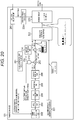
- Fig. 20 is a block diagram illustrating an example of the main configuration of the transmission device 101.
- the transmission device 101 transmits a signal using the 920 MHz band.
- the transmission device 101 can thus be used without a license.
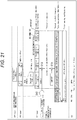
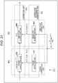
- Fig. 21 illustrates an overall view of a frame structure of a transmit signal transmitted by the transmission device 101.
- the transmission device 101 transmits a signal in frames of 0.189 seconds (about 0.2 seconds or less) each.
- a single continuous transmission time is 0.189 seconds and falls below the continuous transmission time of 0.2 seconds.
- An interval is also provided as appropriate between frames.
- a large number of transmission channels can be allocated, and a relatively vacant channel can be selected for transmission so that a system more resistant to interference can be constructed.
- Application of the present technology enables construction of a high sensitivity transmission/reception system even with the use of such a short frame length.
- Single data transmission includes a super frame in which a plurality of frames is repeated.
- a super frame illustrated in Fig. 21 the frame of 0.189 seconds is repeated 20 times.
- a gap between the frames is a time of at least 2 ms or longer. The gap differs each time depending on a result of carrier sense (that is, a level of congestion of the channel).
- the number of frames that can be transmitted varies slightly depending on a degree of congestion of the channel.
- the signals transmitted in 20 frames are described below as being identical.
- the transmission device 101 includes a GNSS signal reception unit 201, a payload data generation unit 202, an ID/CRC addition unit 203, an FEC processing unit 204, a repeating unit 205, a guard bit addition unit 206, a key stream generation unit 211, an AND gate 212, an EXOR gate 213, a Gold code generation unit 214, an EXOR gate 215, a sync generation unit 221, an interleave unit 222, a modulation unit 223, and a frequency/timing control unit 224.
- the GNSS signal reception unit 201 receives a GNSS signal, acquires 1 pulse per second (PPS) signal and current time (GNSS time) included in the GNSS signal, and supplies the acquired information to the frequency/timing control unit 224 as a clock signal.
- the GNSS signal reception unit 201 also acquires location information (latitude, longitude, and altitude) of the transmission device 101 from the GNSS signal, and supplies the information to the payload data generation unit 202 as sensor information obtained by sensing the location.
- the payload data generation unit 202 generates payload data to be the payload of a wireless signal from the location information supplied from the GNSS signal reception unit 201, and supplies the payload data to the ID/CRC addition unit 203.
- information to be the payload data is not limited to the location information.
- the ID/CRC addition unit 203 adds identification information (ID) of the transmission device 101 and a cyclic redundancy check (CRC) code to the payload data from the payload data generation unit 202, thereby generating a forward error correction (FEC) target unit to be subjected to FEC processing and supplying the FEC target unit to the FEC processing unit 204.
- ID identification information
- CRC cyclic redundancy check
- FEC forward error correction
- the FEC processing unit (coding unit) 204 performs FEC processing on the FEC target unit from the ID/CRC addition unit 203, and supplies an FEC frame obtained as a result thereof to the repeating unit 205.
- the FEC processing unit 204 performs error correction coding on the FEC target unit as the FEC processing on the FEC target unit, and supplies an error correction code obtained by the error correction coding to the repeating unit 205.
- the FEC processing unit 204 performs, for example, LDPC coding on the FEC target unit, and supplies an LDPC code obtained by the LDPC coding to the repeating unit 205.
- the error correction code is not limited to the LDPC code.
- the error correction code for example, a convolutional code, a turbo code, or the like can be adopted.
- the repeating unit 205 generates a repeat unit in which the LDPC code from the FEC processing unit 204 is repeatedly arranged, and supplies the repeat unit to the guard bit addition unit 206.
- the guard bit addition unit 206 adds (inserts) a guard bit to the repeat unit from the repeating unit 205 and supplies it to the EXOR gate 213.
- processing such as fast Fourier transform (FFT) or the like may be used in received signal processing.
- the FFT may perform an operation equivalent to that in which the received signal is repeatedly transmitted, where errors are likely to occur at a front end and a rear end of the received signal.
- the guard bits are added to the front end and the rear end of the signal sequence to be able to prevent deterioration of a required signal even if signal processing such as the FFT is performed on the side of the receiver.
- the key stream generation unit 211 generates a key stream used for encryption and supplies the key stream to the AND gate 212.
- a switching signal for switching between enabling and disabling of encryption at the EXOR gate 213 is supplied to the AND gate 212.
- the switching signal is, for example, a signal that is at logic one (for example, high level) in a case where encryption is enabled and at logic zero (for example, low level) in a case where encryption is disabled.
- the switching signal can be set according to the application, for example.
- the switching signal can be set to enable encryption of the whole or a part of the repeat unit supplied from the guard bit addition unit 206 to the EXOR gate 213.
- the switching signal can also be set to disable encryption of the whole repeat unit supplied from the guard bit addition unit 206 to the EXOR gate 213.
- the AND gate 212 calculates the logical AND of the switching signal and the key stream from the key stream generation unit 211, and supplies the logical AND to the EXOR gate 213. As a result, the key stream is supplied from the AND gate 212 to the EXOR gate 213 only while encryption is enabled by the switching signal.
- the EXOR gate 213 calculates the exclusive OR of the repeat unit from the card bit addition unit 206 and the key stream from the AND gate 212, thereby encrypting the repeat unit by stream encryption (method).
- the EXOR gate 213 supplies the encrypted repeat unit to the EXOR gate 215.
- the EXOR gate 213 encrypts the repeat unit corresponding to a period in which the key stream from the AND gate 212 is supplied, that is, a period in which the switching signal is at logic one.
- the EXOR gate 213 there is a case where all or a part of the repeat unit is encrypted, or all of the repeat unit is not encrypted.
- the Gold code generation unit 214 for example uses two M-sequence generators to generate a Gold code, for example, as a scrambling sequence of the same size (bit length) as the repeat unit from the EXOR gate 213, thereby supplying the scrambling sequence to the EXOR gate 215.
- the EXOR gate 215 scrambles the repeat unit by calculating the exclusive OR of the repeat unit from the EXOR gate 213 and the scrambling sequence from the Gold code generation unit 214, and supplies the scrambled data to the interleave unit 222.
- the sync generation unit 221 generates, for example, a predetermined pseudo noise (PN) sequence such as an M-sequence as a synchronization signal, and supplies the synchronization signal to the interleave unit 222.
- PN pseudo noise
- the synchronization signal generated by the sync generation unit 221 is a signal known by the transmission device 101 and the high sensitivity reception device 102. Since the synchronization signal is known by the transmission device 101 and the high sensitivity reception device 102, the high sensitivity reception device 102 can perform synchronization of the wireless signal from the transmission device 101 and receive the wireless signal from the transmission device 101 in a robust manner.
- An initial value of the M-sequence may be any value as long as it is common for transmission and reception. Moreover, the initial value of the M-sequence can be changed depending on the ID.
- the interleave unit 222 alternately interleaves (multiplexes) a bit sequence d (0), d (1), ... as the repeat unit from the EXOR gate 213 and a bit sequence r (0), r (1), ... as the synchronization signal from the sync generation unit 221, and supplies an interleaved sequence r (0), d (0), r (1), d (1)... obtained by the interleaving to the modulation unit 223.
- the modulation unit 223 performs, for example, ⁇ /2 shift binary phase shift keying ( ⁇ /2 shift BPSK) modulation using the interleaved sequence supplied from the interleave unit 222 and transmits, for example, a wireless signal in the 920 MHz band as a modulated signal obtained by the modulation. Note that the modulation unit 223 transmits the wireless signal at transmission timing and transmission frequency controlled by the frequency/timing control unit 224.
- ⁇ /2 shift binary phase shift keying ⁇ /2 shift BPSK
- the frequency/timing control unit 224 sets the transmission timing and transmission frequency of the wireless signal transmitted by the modulation unit 223 according to the ID of the transmission device 101 and the like, and controls the modulation unit 223 such that the wireless signal is transmitted at the transmission timing and transmission frequency.
- the frequency/timing control unit 224 controls the modulation unit 223 in synchronization with the clock signal from the GNSS signal reception unit 201. That is, the frequency/timing control unit 224 recognizes whether the current timing is a grid timing (grid time) which is the timing known (predetermined) in the transmission device 101 and the high sensitivity reception device 102 according to the clock signal from the GNSS signal reception unit 201, for example, and controls the modulation unit 223 such that packet transmission is started at the grid timing.
- grid timing grid timing
- the transmit signal is transmitted as a frame of 0.2 seconds or less in a state in which the synchronization signal (SYNC) known to the reception device is evenly scattered. Therefore, the transmission device 101 can reduce deterioration in the reception sensitivity. In other words, the transmission device 101 can realize transmission of a wireless signal for a longer range while reducing an increase in power consumption of the entire device.
- SYNC synchronization signal
- step S101 the payload data generation unit 202 generates an MSDU as the payload data and supplies it to the ID/CRC addition unit 203, and the processing proceeds to step S102.
- step S102 the ID/CRC addition unit 203 adds the ID of the transmission device 101 and the CRC code to the payload data from the payload data generation unit 202, thereby generating a PSDU as the FEC target unit.
- the ID/CRC addition unit 203 supplies the FEC target unit to the FEC processing unit 204, and the processing proceeds from step S102 to step S103.
- step S103 the FEC processing unit 204 performs LDPC coding on the FEC target unit from the ID/CRC addition unit 203 and supplies, to the repeating unit 205, an FEC frame corresponding to one codeword of an LDPC code obtained by the LDPC coding, and the processing proceeds to step S104.
- step S104 the repeating unit 205 generates a repeat unit in which the LDPC code from the FEC processing unit 204 is repeatedly arranged and supplies the repeat unit to the guard bit addition unit 206, and the processing proceeds to step S105.
- step S105 the guard bit addition unit 206 adds a guard bit to the repeat unit from the repeating unit 205 and supplies the repeat unit to the EXOR gate 213, and the processing proceeds to step S106.
- step S106 the EXOR gate 213 encrypts the repeat unit from the guard bit addition unit 206 and supplies a resultant encryption stream to the EXOR gate 215.
- the EXOR gate 215 scrambles the encryption stream from the EXOR gate 213 and supplies a resultant scrambled stream to the interleave unit 222, and the processing proceeds from step S106 to step S107.
- step S107 the interleave unit 222 interleaves the scrambled stream from the EXOR gate 213 and the synchronization signal from the sync generation unit 221 and supplies a PPDU obtained by the interleaving to the modulation unit 223, and the processing proceeds to step S108.
- step S108 the modulation unit 223 performs BPSK modulation or chirp modulation using the PPDU supplied from the interleave unit 222 to generate and transmit a wireless signal in the 920 MHz band, for example, and the processing ends.
- Fig. 21 is a diagram illustrating an example of a first format of data (signal) handled by the transmission device 101.
- the diagram illustrates a data format in a case where, for example, 50.8 kbps is adopted as a modulation rate (transmission rate) of modulation performed by the modulation unit 223 in a new communication system.
- MSDU media access control
- the 128-bit MSDU is added with a 32-bit ID of the transmission device 101 and a 24-bit CRC code by the ID/CRC addition unit 203, thereby forming a 184-bit unit called a physical layer service unit (PSDU) as the FEC target unit.
- PSDU physical layer service unit
- the repeat unit includes the arrangement of the 736-bit LDPC code repeated six times and also the 384 bits being a portion of the 736-bit LDPC code.
- the first 384 bits of the 736-bit LDPC code can be adopted, for example.
- the 384 bits being a portion of the 736-bit LDPC code arranged in the repeat unit can be selected according to a predetermined optimization pattern, for example.
- the 4808-bit repeat unit is encrypted to be an encryption stream and is further scrambled to be a scrambled stream.
- the scrambled stream is a 4808-bit bit sequence d (0), d (1), ..., d (4807) of the same size as the repeat unit to which the guard bits are added.
- the sync generation unit 221 generates, for example, a bit sequence r (0), r (1), ..., r (4087) as a 4808-bit synchronization signal (Sync) of the same size as the scrambled stream.
- bit sequence r (0), r (1), ... r (4087) as the 4808-bit synchronization signal and the bit sequence d (0), d (1), ..., d (4807) as the 4808-bit scrambled stream are interleaved by interleave unit 222.
- bit sequence r (0), d (0), r (1), d (1), ... as a PPDU of 9616 bits ( 4808 bits + 4808 bits) in which bits as the synchronization signals are periodically inserted.
- bit sequence r (0), r (1), ..., r (4807) as the 4808-bit synchronization signal and the bit sequence d (0), d (1), ..., d (4807) as the 4808-bit scrambled stream are interleaved according to a C program below, for example.
- the 9616-bit PPDU is subjected to 50.8 kbps ⁇ /2 shift BPSK modulation by the modulation unit 223 and transmitted as a wireless signal.
- the transmission time of the 9616-bit PPDU is about 189.4 ms. Since the time is less than 0.2 seconds defined by the ARIB standard, the transmission can be repeated a plurality of times with a short transmission pause time.
- the transmission device 101 repeatedly transmits the PPDU as a packet 20 times, for example.
- the transmission is repeated such many times so that information can be transmitted more reliably even if there is an influence of fading or the like, for example.
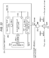
- Fig. 22 is a block diagram illustrating an example of the configuration of the key stream generation unit 211 of Fig. 20 .
- the key stream generation unit 211 includes a key generation unit 251, a nonce generation unit 252, a block encryption unit 253, and a P/S conversion unit 254.
- the key stream generation unit 211 generates a key stream used for encryption.
- the key stream generation unit 211 generates a 1664-bit key stream for the first format and generates a 4808-bit key stream for the second format.
- the key generation unit 251 generates 128 bits of key information.
- the internal structure of the key generation unit 251 is not disclosed so that security of encryption is ensured.
- the key generation unit 251 may have any configuration as long as the internal structure is not easily guessed.
- the key generation unit 251 can generate the key information by acquiring the GNSS time from the GNSS signal reception unit 201 ( Fig. 20 ) and adding zero data such that the bit length equals 128 bits, for example.
- the key generation unit 251 supplies the generated key information to the block encryption unit 253.
- the nonce generation unit 252 generates 128 bits of number used once (nonce). As for the nonce, it is expected that the value is different at each timing obtained by dividing a bit clock by 128.
- the nonce generation unit 252 can include, for example, a 128-bit counter.
- the nonce generation unit 252 can generate the nonce by, for example, initializing the counter to a predetermined count value before the start of transmission of a wireless signal, and then incrementing the count value by one at every timing obtained by dividing the bit clock by 128.
- the nonce generation unit 252 supplies the generated nonce to the block encryption unit 253.
- the block encryption unit 253 generates a 128-bit block cipher using the key information from the key generation unit 251 and the nonce from the nonce generation unit 252, and supplies the block cipher to the P/S conversion unit 254.
- an Advanced Encryption Standard (AES) code for example, an Advanced Encryption Standard (AES) code, a CLEFIA code, or the like can be used.
- AES Advanced Encryption Standard
- CLEFIA CLEFIA code
- the P/S conversion unit 254 performs parallel to serial (P/S) conversion on the 128-bit block cipher from the block encryption unit 253 into one bits to generate a serial (1-bit) key stream, and supplies it to the AND gate 212.
- P/S parallel to serial
- the P/S conversion unit 254 generates a 4808-bit key stream.
- Fig. 24 is a diagram illustrating an example of the main configuration of a reception device which is an embodiment of a signal processing apparatus to which the present technology is applied.
- the high sensitivity reception device 102 receives a signal transmitted from the transmission device 101. Therefore, the received signal has a format in which, as described with reference to Figs. 20 and 21 , one frame includes 9616 symbols with a symbol of unknown information (data) and a symbol of known information (synchronization signal) being alternately arranged.
- the high sensitivity reception device 102 includes an antenna 351, a low noise amplification unit 352, a band-pass filter (BPF) 353, an antenna 354, a GNSS reception unit 355, a carrier oscillation unit 356, a multiplication unit 357, a 90-degree shifter 358, a multiplication unit 359, an A/D conversion unit 360, a memory 361, and a signal processing unit 362.
- BPF band-pass filter
- the low noise amplification unit 352 is configured to perform processing related to signal amplification.
- the low noise amplification unit 352 receives a wireless signal via the antenna 351, amplifies the received signal, and supplies the amplified signal to the band-pass filter 353.
- this low noise amplification unit 352 can be implemented by an arbitrary configuration.
- the low noise amplification unit 352 may be configured by a circuit, an LSI, a system LSI, a processor, a module, a unit, a set, a device, an apparatus, a system, or the like. Moreover, a plurality of those may be combined.
- the same type of configuration such as a plurality of the circuits, a plurality of the processors, or the like may be combined, or different types of configurations such as the circuit and the LSI may be combined.
- the low noise amplification unit 352 may include an operational amplifier or the like.
- the band-pass filter 353 is configured to perform processing related to band limitation.
- the band-pass filter 353 removes an unnecessary frequency component from the received signal and supplies it to the multiplication unit 357 and the multiplication unit 359.
- this band-pass filter 353 can be implemented by an arbitrary configuration.
- the band-pass filter 353 may be configured by a circuit, an LSI, a system LSI, a processor, a module, a unit, a set, a device, an apparatus, a system, or the like. Moreover, a plurality of those may be combined.
- the same type of configuration such as a plurality of the circuits, a plurality of the processors, or the like may be combined, or different types of configurations such as the circuit and the LSI may be combined.
- the band-pass filter 353 may have a CPU and a memory, and perform the aforementioned processing by the CPU executing a program using the memory.
- the GNSS reception unit 355 is configured to perform processing related to reception of a GNSS signal.
- the GNSS reception unit 355 receives the GNSS signal transmitted from a GNSS satellite via the antenna 354.
- the GNSS reception unit 355 supplies time information (GNSS time information) or the like included in the GNSS signal to the carrier oscillation unit 356.
- the GNSS reception unit 355 can be implemented by an arbitrary configuration.
- the GNSS reception unit 355 may be configured by a circuit, an LSI, a system LSI, a processor, a module, a unit, a set, a device, an apparatus, a system, or the like. Moreover, a plurality of those may be combined.
- the same type of configuration such as a plurality of the circuits, a plurality of the processors, or the like may be combined, or different types of configurations such as the circuit and the LSI may be combined.
- the GNSS reception unit 355 may be configured by a receiving circuit, a signal processing circuit, and the like.
- the carrier oscillation unit 356 is configured to perform processing related to carrier generation. For example, the carrier oscillation unit 356 generates a signal with a carrier frequency of a predetermined frequency used for transmission and reception. For example, in a case where a signal transmitted in the 920 MHz band is received, the carrier oscillation unit 356 oscillates at 920 MHz. Note that the carrier oscillation unit 356 appropriately corrects the frequency of the carrier generated using the GNSS time information supplied from the GNSS reception unit 355, and can generate the carrier with a more accurate frequency. The carrier oscillation unit 356 supplies the oscillation signal (carrier signal) to the multiplication unit 357 and the 90-degree shifter 358.
- the carrier oscillation unit 356 supplies the oscillation signal (carrier signal) to the multiplication unit 357 and the 90-degree shifter 358.
- this carrier oscillation unit 356 can be implemented by an arbitrary configuration.
- the carrier oscillation unit 356 may be configured by a circuit, an LSI, a system LSI, a processor, a module, a unit, a set, a device, an apparatus, a system, or the like. Moreover, a plurality of those may be combined. At that time, for example, the same type of configuration such as a plurality of the circuits, a plurality of the processors, or the like may be combined, or different types of configurations such as the circuit and the LSI may be combined.
- the carrier oscillation unit 356 may have an oscillator circuit.
- the multiplication unit 357 is configured to perform processing related to multiplication. For example, the multiplication unit 357 multiplies the received signal supplied from the band-pass filter 353 by the carrier signal supplied from the carrier oscillation unit 356 to generate a baseband in-phase signal (I signal). The multiplication unit 357 supplies the I signal to the A/D conversion unit 360. Note that this multiplication unit 357 can be implemented by an arbitrary configuration. For example, the multiplication unit 357 may be configured by a circuit, an LSI, a system LSI, a processor, a module, a unit, a set, a device, an apparatus, a system, or the like. Moreover, a plurality of those may be combined.
- the same type of configuration such as a plurality of the circuits, a plurality of the processors, or the like may be combined, or different types of configurations such as the circuit and the LSI may be combined.
- the multiplication unit 357 may have a CPU and a memory, and perform the aforementioned processing by the CPU executing a program using the memory.
- the 90-degree shifter 358 is configured to perform processing related to phase shift. For example, the 90-degree shifter 358 shifts the phase of the carrier signal supplied from the carrier oscillation unit 356 by 90 degrees. The 90-degree shifter 358 supplies the phase-shifted carrier signal to the multiplication unit 359. Note that this 90-degree shifter 358 can be implemented by an arbitrary configuration.
- the 90-degree shifter 358 may be configured by a circuit, an LSI, a system LSI, a processor, a module, a unit, a set, a device, an apparatus, a system, or the like. Moreover, a plurality of those may be combined.
- the same type of configuration such as a plurality of the circuits, a plurality of the processors, or the like may be combined, or different types of configurations such as the circuit and the LSI may be combined.
- the 90-degree shifter 358 may have a CPU and a memory, and perform the aforementioned processing by the CPU executing a program using the memory.
- the multiplication unit 359 is configured to perform processing related to multiplication. For example, the multiplication unit 359 multiplies the received signal supplied from the band-pass filter 353 by the 90-degree phase-shifted carrier signal supplied from the 90-degree shifter 358 to generate a baseband quadrature signal (Q signal). The multiplication unit 359 supplies the Q signal to the A/D conversion unit 360.
- this multiplication unit 359 can be implemented by an arbitrary configuration.
- the multiplication unit 359 may be configured by a circuit, an LSI, a system LSI, a processor, a module, a unit, a set, a device, an apparatus, a system, or the like. Moreover, a plurality of those may be combined.
- the same type of configuration such as a plurality of the circuits, a plurality of the processors, or the like may be combined, or different types of configurations such as the circuit and the LSI may be combined.
- the multiplication unit 359 may have a CPU and a memory, and perform the aforementioned processing by the CPU executing a program using the memory.
- the A/D conversion unit 360 is configured to perform processing related to A/D conversion. For example, the A/D conversion unit 360 performs A/D conversion on each of the I signal and Q signal supplied, and supplies digital data thereof to the memory 361 for storage.
- the A/D conversion unit 360 may be configured by a circuit, an LSI, a system LSI, a processor, a module, a unit, a set, a device, an apparatus, a system, or the like. Moreover, a plurality of those may be combined. At that time, for example, the same type of configuration such as a plurality of the circuits, a plurality of the processors, or the like may be combined, or different types of configurations such as the circuit and the LSI may be combined.
- the A/D conversion unit 360 may be configured by a predetermined A/D conversion circuit.
- the memory 361 has a predetermined storage medium, acquires the digital data of the I signal and the Q signal supplied from the A/D conversion unit 360, and stores the digital data in the storage medium.
- This storage medium may be of any type such as a semiconductor memory, a magnetic recording medium such as a hard disk, or any other storage medium, for example.
- the A/D conversion unit 360 performs A/D conversion for 20 seconds, for example, with 8-bit accuracy and the conversion rate (101.6 KHz) twice the modulation rate
- the memory 361 accumulates about four megabytes (4 Mbytes) of digital data of the I signal and Q signal together.
- the signal processing unit 362 is configured to perform signal processing. For example, the signal processing unit 362 reads the digital data of the I signal and the Q signal accumulated in the memory 361, performs decoding processing, and restores payload data being transmitted. The signal processing unit 362 outputs the restored payload data.
- the high sensitivity reception device 102 can receive and decode the transmit signal transmitted by the transmission device 101. That is, the high sensitivity reception device 102 can obtain transmit data TM by receiving and properly decoding a transmit frame transmitted as a frame of 0.2 seconds or less in a state in which a known synchronization pattern (SYNC) is almost evenly scattered. Therefore, the high sensitivity reception device 102 can realize transmission of a wireless signal for a longer range while suppressing an increase in power consumption of the entire device.
- SYNC known synchronization pattern
- Fig. 25 is a block diagram illustrating an example of the main configuration of the signal processing unit 362.
- the signal processing unit 362 includes a separation unit 371, a delay unit 372, a frequency sample generation unit 373, a significant component extraction unit 374, an inverse transform unit 375, a frame synchronization unit 376, a correction unit 377, an integration unit 378, a despreading unit 379, and low-density parity-check codes (LDPC) 380.
- LDPC low-density parity-check codes
- the separation unit 371 is configured to perform processing related to data separation. For example, the separation unit 371 separates unknown information (data) and known information (synchronization signal) that are included in the digital data (IQ signal) read from the memory 361. The separation unit 371 supplies the separated data (unknown information) to the delay unit 372, and supplies the separated synchronization signal (known information) to the frequency sample generation unit 373.
- this separation unit 371 can be implemented by an arbitrary configuration.
- the separation unit 371 may be configured by a circuit, an LSI, a system LSI, a processor, a module, a unit, a set, a device, an apparatus, a system, or the like. Moreover, a plurality of those may be combined. At that time, for example, the same type of configuration such as a plurality of the circuits, a plurality of the processors, or the like may be combined, or different types of configurations such as the circuit and the LSI may be combined.
- the delay unit 372 is configured to perform processing related to data delay.
- the delay unit 372 has a buffer and stores one frame of data supplied from the separation unit 371 in the buffer. Then, the delay unit 372 supplies the stored data to the correction unit 377 according to control of the frame synchronization unit 376.
- this delay unit 372 can be implemented by an arbitrary configuration.
- the delay unit 372 may be configured by a circuit, an LSI, a system LSI, a processor, a module, a unit, a set, a device, an apparatus, a system, or the like. Moreover, a plurality of those may be combined. At that time, for example, the same type of configuration such as a plurality of the circuits, a plurality of the processors, or the like may be combined, or different types of configurations such as the circuit and the LSI may be combined.
- the frequency sample generation unit 373 is configured to perform processing related to generation of frequency samples. For example, the frequency sample generation unit 373 generates complex frequency samples from the synchronization signal supplied from the separation unit 371. The frequency sample generation unit 373 supplies the generated complex frequency samples to the significant component extraction unit 374. Note that this frequency sample generation unit 373 can be implemented by an arbitrary configuration.
- the frequency sample generation unit 373 may be configured by a circuit, an LSI, a system LSI, a processor, a module, a unit, a set, a device, an apparatus, a system, or the like. Moreover, a plurality of those may be combined. At that time, for example, the same type of configuration such as a plurality of the circuits, a plurality of the processors, or the like may be combined, or different types of configurations such as the circuit and the LSI may be combined.
- the significant component extraction unit 374 is configured to perform processing related to extraction of significant components of the frequency samples. For example, the significant component extraction unit 374 extracts a plurality of complex frequency samples as significant components from a large number of the complex frequency samples supplied from the frequency sample generation unit 373. The significant component extraction unit 374 supplies the plurality of complex frequency samples extracted to the inverse transform unit 375. The significant component extraction unit 374 also detects a peak of the complex frequency sample of each frame and notifies the frame synchronization unit 376 of it. Note that this significant component extraction unit 374 can be implemented by an arbitrary configuration.
- the significant component extraction unit 374 may be configured by a circuit, an LSI, a system LSI, a processor, a module, a unit, a set, a device, an apparatus, a system, or the like. Moreover, a plurality of those may be combined. At that time, for example, the same type of configuration such as a plurality of the circuits, a plurality of the processors, or the like may be combined, or different types of configurations such as the circuit and the LSI may be combined.
- the inverse transform unit 375 is configured to perform processing related to inverse transform. For example, the inverse transform unit 375 transforms the plurality of complex frequency samples in the frequency domain supplied from the significant component extraction unit 374 into a channel information sample in the time domain. The inverse transform unit 375 supplies the generated channel information sample to the correction unit 377.
- this inverse transform unit 375 can be implemented by an arbitrary configuration.
- the inverse transform unit 375 may be configured by a circuit, an LSI, a system LSI, a processor, a module, a unit, a set, a device, an apparatus, a system, or the like. Moreover, a plurality of those may be combined. At that time, for example, the same type of configuration such as a plurality of the circuits, a plurality of the processors, or the like may be combined, or different types of configurations such as the circuit and the LSI may be combined.
- the frame synchronization unit 376 is configured to perform processing related to frame synchronization. For example, the frame synchronization unit 376 synchronizes data on a frame-by-frame basis by controlling the timing for reading the one frame of data stored in the delay unit 372. The frame synchronization unit 376 for example controls the delay unit 372 to cause the data to be read from the delay unit 372 at a timing (a synchronized timing) corresponding to the notification from the significant component extraction unit 374. Note that this frame synchronization unit 376 can be implemented by an arbitrary configuration.
- the frame synchronization unit 376 may be configured by a circuit, an LSI, a system LSI, a processor, a module, a unit, a set, a device, an apparatus, a system, or the like. Moreover, a plurality of those may be combined. At that time, for example, the same type of configuration such as a plurality of the circuits, a plurality of the processors, or the like may be combined, or different types of configurations such as the circuit and the LSI may be combined.
- the frame synchronization unit 376 may have a CPU and a memory, and perform the aforementioned processing by the CPU executing a program using the memory.
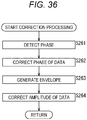
- the correction unit 377 is configured to perform processing related to data correction. For example, the correction unit 377 corrects the data supplied from the delay unit 372 on the basis of the channel information sample (channel information sample obtained by transforming the plurality of frequency samples) supplied from the inverse transform unit 375. For example, the correction unit 377 corrects the phase of the data. Moreover, the correction unit 377 may also be adapted to be able to correct the amplitude of the data. The correction unit 377 supplies the data after correction to the integration unit 378. Note that this correction unit 377 can be implemented by an arbitrary configuration.
- the correction unit 377 may be configured by a circuit, an LSI, a system LSI, a processor, a module, a unit, a set, a device, an apparatus, a system, or the like. Moreover, a plurality of those may be combined. At that time, for example, the same type of configuration such as a plurality of the circuits, a plurality of the processors, or the like may be combined, or different types of configurations such as the circuit and the LSI may be combined.
- the integration unit 378 is configured to perform processing related to integration of data. For example, the integration unit 378 integrates the data supplied from the correction unit 377. By integrating many short-time frames in such a manner, the effective SNR can be improved without exceeding the limit of the maximum transmission time defined in the Radio Law.
- the integration unit 378 supplies a result of the integration to the despreading unit 379.
- this integration unit 378 can be implemented by an arbitrary configuration.
- the integration unit 378 may be configured by a circuit, an LSI, a system LSI, a processor, a module, a unit, a set, a device, an apparatus, a system, or the like. Moreover, a plurality of those may be combined.
- the same type of configuration such as a plurality of the circuits, a plurality of the processors, or the like may be combined, or different types of configurations such as the circuit and the LSI may be combined.
- the integration unit 378 may have a CPU and a memory, and perform the aforementioned processing by the CPU executing a program using the memory.
- the despreading unit 379 is configured to perform processing related to despreading of data. For example, the despreading unit 379 despreads data by multiplying the data by a Gold code or the like. The despreading unit 379 further improves the SNR by integrating the LDPC code repeated six times in a frame, and then supplies the result to the LDPC 180. Note that this despreading unit 379 can be implemented by an arbitrary configuration.
- the despreading unit 379 may be configured by a circuit, an LSI, a system LSI, a processor, a module, a unit, a set, a device, an apparatus, a system, or the like. Moreover, a plurality of those may be combined.
- the despreading unit 379 may have a CPU and a memory, and perform the aforementioned processing by the CPU executing a program using the memory.
- the LDPC 380 is configured to perform processing related to low density parity check codes. For example, the LDPC 380 performs error determination using a frame check sequence added to transmit data, and performs correction processing as needed. The LDPC 380 outputs the checked data. Note that this LDPC 380 can be implemented by an arbitrary configuration.
- the LDPC 380 may be configured by a circuit, an LSI, a system LSI, a processor, a module, a unit, a set, a device, an apparatus, a system, or the like. Moreover, a plurality of those may be combined.
- the same type of configuration such as a plurality of the circuits, a plurality of the processors, or the like may be combined, or different types of configurations such as the circuit and the LSI may be combined.
- the LDPC 380 may have a CPU and a memory, and perform the aforementioned processing by the CPU executing a program using the memory.
- Fig. 26 is a schematic diagram illustrating an example of the main configuration of the separation unit 371.
- the separation unit 371 includes a switch 401.
- the switch 401 is a one-input two-output switch with an input terminal thereof connected to the input of the signal processing unit 362 (that is, the memory 361), one output connected to the delay unit 372, and another output connected to the frequency sample generation unit 373.
- the received signal (IQ signal) read from the memory 361 is supplied to the switch 401.
- the switch 401 supplies symbols of data, which is the unknown information included in the received signal, to the delay unit 372 and supplies symbols of the synchronization signal, which is the known information, to the frequency sample generation unit 373.
- the switch 401 is configured to switch alternately at intervals of the symbols.
- this switch 401 can be implemented by an arbitrary configuration.
- the switch 401 may be configured by a circuit, an LSI, a system LSI, a processor, a module, a unit, a set, a device, an apparatus, a system, or the like. Moreover, a plurality of those may be combined.
- the same type of configuration such as a plurality of the circuits, a plurality of the processors, or the like may be combined, or different types of configurations such as the circuit and the LSI may be combined.
- the switch 401 may be configured by a switch circuit or the like.
- Fig. 27 is a block diagram illustrating an example of the main configuration of the frequency sample generation unit 373. As illustrated in Fig. 27 , the frequency sample generation unit 373 has a known data multiplication unit 411 and a transform unit 412.
- the known data multiplication unit 411 is configured to perform processing related to multiplication of known data.
- the known data multiplication unit 411 multiplies each symbol of the synchronization signal supplied from the separation unit 371 by known data (+1 or -1) to generate a channel information sample (p (k) (0 ⁇ k ⁇ (N - 1))).
- This known data is the value with which the channel information samples (p (k)) are all +1 (on the real axis) in a case where synchronization is achieved, as described with reference to Figs. 10 and 11 .
- the known data multiplication unit 411 supplies the synchronization signal multiplied by the known data (channel information sample (p (k))) to the transform unit 412.
- this known data multiplication unit 411 can be implemented by an arbitrary configuration.
- the known data multiplication unit 411 may be configured by a circuit, an LSI, a system LSI, a processor, a module, a unit, a set, a device, an apparatus, a system, or the like. Moreover, a plurality of those may be combined. At that time, for example, the same type of configuration such as a plurality of the circuits, a plurality of the processors, or the like may be combined, or different types of configurations such as the circuit and the LSI may be combined.
- the known data multiplication unit 411 may have a CPU and a memory, and perform the aforementioned processing by the CPU executing a program using the memory.
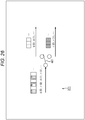
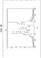
- the transform unit 412 is configured to perform processing related to transformation of the channel information sample. For example, the transform unit 412 transforms the channel information sample supplied from the known data multiplication unit 411 into a complex frequency sample C (f). That is, as in a graph illustrated in Fig. 28 , a spectrum distribution of complex frequencies is obtained. Note that this transform method is arbitrary.
- the transform unit 412 may be adapted to perform fast Fourier transform (FFT).
- FFT fast Fourier transform
- the transform unit 412 for example transforms the channel information sample for one frame into the complex frequency sample C (f).
- the transform unit 412 supplies the complex frequency sample C (f) obtained to the significant component extraction unit 374.
- this transform unit 412 can be implemented by an arbitrary configuration.
- the transform unit 412 may be configured by a circuit, an LSI, a system LSI, a processor, a module, a unit, a set, a device, an apparatus, a system, or the like.
- a plurality of those may be combined.
- the same type of configuration such as a plurality of the circuits, a plurality of the processors, or the like may be combined, or different types of configurations such as the circuit and the LSI may be combined.
- the transform unit 412 may have a CPU and a memory, and perform the aforementioned processing by the CPU executing a program using the memory.
- Fig. 29 is a block diagram illustrating an example of the main configuration of the significant component extraction unit 374.
- the significant component extraction unit 374 includes a sample and hold unit 421, a peak detection unit 422, and a significant component selection unit 423.
- the sample and hold unit 421 has a storage area such as a buffer, for example, and is configured to perform processing related to holding of frequency samples.
- the sample and hold unit 421 holds the complex frequency sample C (f) supplied from the frequency sample generation unit 373. Then, when notified of the detection of a peak from the peak detection unit 422, the sample and hold unit 421 supplies the complex frequency sample held therein to the significant component selection unit 423.
- the sample and hold unit 421 can be configured to hold all frequency samples obtained from the received signal of one frame.
- the sample and hold unit 421 can be configured to preselect and hold only a low frequency component of the frequency samples obtained from the received signal of one frame.
- sample and hold unit 421 can be implemented by an arbitrary configuration.
- the sample and hold unit 421 may be configured by a circuit, an LSI, a system LSI, a processor, a module, a unit, a set, a device, an apparatus, a system, or the like.
- a plurality of those may be combined.
- the same type of configuration such as a plurality of the circuits, a plurality of the processors, or the like may be combined, or different types of configurations such as the circuit and the LSI may be combined.
- the sample and hold unit 421 may be configured by a memory, a switch, or the like.
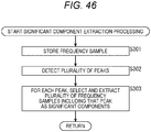
- the peak detection unit 422 is configured to perform processing related to peak detection. For example, the peak detection unit 422 detects a spectrum with a large amplitude from the complex frequency sample C (f) supplied from the frequency sample generation unit 373.
- the spectrum detected may be, for example, a sample with the maximum amplitude or a sample with the amplitude close to the maximum among the complex frequency sample group supplied from the frequency sample generation unit 373.
- the peak detection unit 422 may be adapted to detect a spectrum with a magnitude of the noise level higher than or equal to a predetermined noise level (for example, 5 dB). Upon detecting such a large spectrum, the peak detection unit 422 notifies the frame synchronization unit 376 and the sample and hold unit 421 to that effect.
- the frame synchronization unit 376 controls the delay unit 372 according to the notification to achieve frame synchronization.
- the sample and hold unit 421 supplies the complex frequency sample held therein to the significant component selection unit 423 according to the notification.
- this peak detection unit 422 can be implemented by an arbitrary configuration.
- the peak detection unit 422 may be configured by a circuit, an LSI, a system LSI, a processor, a module, a unit, a set, a device, an apparatus, a system, or the like.
- a plurality of those may be combined.
- the same type of configuration such as a plurality of the circuits, a plurality of the processors, or the like may be combined, or different types of configurations such as the circuit and the LSI may be combined.
- the peak detection unit 422 may have a CPU and a memory, and perform the aforementioned processing by the CPU executing a program using the memory.
- the significant component selection unit 423 is configured to perform processing related to selection of a significant component of the complex frequency sample. For example, the significant component selection unit 423 selects a plurality of the complex frequency samples as significant components from among the complex frequency samples supplied from the sample and hold unit 421.
- the method of selecting the complex frequency samples by the significant component selection unit 423 is arbitrary. As described with reference to Figs. 17 and 18 , the plurality of the complex frequency samples is only required to be selected such that the complex frequency spectrum distribution of the received signal (synchronization signal) is reproduced with higher accuracy.
- the significant component selection unit 423 may select, as the significant components, a peak sample which is a complex frequency sample with a larger amplitude than the surrounding and neighboring samples which are complex frequency samples around the peak sample.
- a peak sample which is a complex frequency sample with a larger amplitude than the surrounding and neighboring samples which are complex frequency samples around the peak sample.
- the easiest example is to simply select one spectrum with the maximum amplitude as the peak sample, and then select two frequency spectra adjacent to the peak spectrum on both sides thereof as the neighboring samples.
- a spectrum with the highest amplitude can be selected as a first peak sample and two spectra adjacent to the first peak sample on both sides thereof can be selected as first neighboring samples, and thereafter a spectrum with the second highest amplitude can be selected as a second peak sample and spectra adjacent to the second peak sample on both sides thereof can be selected as second neighboring samples.
- the neighboring samples may or need not be adjacent to the peak sample.
- the number of the neighboring samples with respect to the peak sample is arbitrary. It may be one or three or more.
- the significant component selection unit 423 selects a spectrum larger than the surrounding as a peak sample f 1 , and selects spectra adjacent thereto on both sides as a neighboring sample f 0 and a neighboring sample f 2 .
- the significant component selection unit 423 supplies the plurality of the complex frequency samples (the peak sample f 1 , the neighboring sample f 0 , and the neighboring sample f 2 ) selected in such a manner to the inverse transform unit 375.
- this significant component selection unit 423 can be implemented by an arbitrary configuration.
- the significant component selection unit 423 may be configured by a circuit, an LSI, a system LSI, a processor, a module, a unit, a set, a device, an apparatus, a system, or the like. Moreover, a plurality of those may be combined. At that time, for example, the same type of configuration such as a plurality of the circuits, a plurality of the processors, or the like may be combined, or different types of configurations such as the circuit and the LSI may be combined.
- the significant component selection unit 423 may have a CPU and a memory, and perform the aforementioned processing by the CPU executing a program using the memory.
- Fig. 30 is a diagram for explaining an example of the main configuration of the inverse transform unit 375.
- a schematic diagram in A of Fig. 30 illustrates an example of the main configuration of the inverse transform unit 375.
- the inverse transform unit 375 includes an oscillator 431-1, an oscillator 431-2, an oscillator 431-3, and a combining unit 432.
- the oscillator 431-1 corresponds to the neighboring sample f 0 (the complex frequency sample of frequency f 0 and magnitude A 0 ) supplied from the significant component extraction unit 374 and generates an oscillation signal of the frequency f 0 and the magnitude A 0 .
- the oscillator 431-2 corresponds to the peak sample f 1 (the complex frequency sample of frequency f 1 and magnitude A 1 ) supplied from the significant component extraction unit 374 and generates an oscillation signal of the frequency f 1 and the magnitude A 1 .
- the oscillator 431-3 corresponds to the neighboring sample f 2 (the complex frequency sample of frequency f 2 and magnitude A 2 ) supplied from the significant component extraction unit 374 and generates an oscillation signal of the frequency f 2 and the magnitude A 2 .
- the magnitudes (A 0 , A 1 , and A 2 ) are typically complex numbers.
- the oscillators 431-1 to 431-3 need not be distinguished from one another, they are referred to as an oscillator 431. That is, the inverse transform unit 375 has the oscillator 431 for each of the plurality of the complex frequency samples (the peak sample or the neighboring sample) supplied from the significant component extraction unit 374.
- the oscillation signal output from each oscillator 431 is a signal obtained by transforming the corresponding complex frequency sample into the time domain. These signals are supplied to the combining unit 432.
- the combining unit 432 combines the oscillation signals supplied from the oscillators 431 as in the following expression (2), for example, and supplies a combined signal (channel information sample) to the correction unit 377.
- the configuration of the inverse transform unit 375 is arbitrary.
- the inverse transform unit may be configured by an inverse Fourier transform unit (FFT) 433.
- the inverse Fourier transform unit 433 receives the plurality of frequency samples supplied from the significant component extraction unit 374 and performs inverse Fourier transform on the frequency samples, thereby transforming the frequency samples into a channel information sample in the time domain. That is, a combined result similar to that of the aforementioned expression (2) is obtained.
- the inverse Fourier transform unit 433 supplies the obtained channel information sample to the correction unit 377.
- the inverse transform unit 375 performs the inverse transform on the plurality of the complex frequency samples as significant components into the channel information sample m (t). That is, this channel information sample m (t) reproduces the frequency deviation of the received signal with higher accuracy.
- the channel information sample m (t) is typically represented by a complex number.
- Fig. 31 is a block diagram illustrating an example of the main configuration of the correction unit 377.
- the correction unit 377 includes a phase detection unit 441, a phase correction unit 442, an envelope generation unit 443, and an amplitude correction unit 444.
- the phase detection unit 441 performs processing related to detection of a correction amount for the phase. For example, the phase detection unit 441 calculates a correction amount ⁇ (t) for the phase from the channel information sample m (t) supplied from the inverse transform unit 375. For example, the phase detection unit 441 calculates the correction amount ⁇ (t) for the phase as in the following expression (3). The phase detection unit 441 supplies the correction amount ⁇ (t) calculated for the phase to the phase correction unit 442.
- ⁇ t tan ⁇ 1 m t
- the phase detection unit 441 detects the correction amount for the phase by using the channel information obtained from the plurality of frequency samples.
- the correction amount can thus be calculated with higher accuracy.
- phase detection unit 441 can be implemented by an arbitrary configuration.
- the phase detection unit 441 may be configured by a circuit, an LSI, a system LSI, a processor, a module, a unit, a set, a device, an apparatus, a system, or the like.
- a plurality of those may be combined.
- the same type of configuration such as a plurality of the circuits, a plurality of the processors, or the like may be combined, or different types of configurations such as the circuit and the LSI may be combined.
- the phase detection unit 441 may have a CPU and a memory, and perform the aforementioned processing by the CPU executing a program using the memory.
- the phase correction unit 442 performs processing related to phase correction. For example, the phase correction unit 442 multiplies the data supplied from the delay unit 372 by a signal e -j ⁇ (t) on the basis of the correction amount ⁇ (t) supplied from the phase detection unit 441, thereby correcting the phase of the data. The phase correction unit 442 supplies the corrected data to the amplitude correction unit 444.
- the phase correction unit 442 can thus correct the received signal using the channel information obtained from the plurality of frequency samples, thereby being able to correct the phase with higher accuracy as described with reference to Figs. 17 and 18 . Therefore, deterioration in the reception sensitivity can be reduced.
- phase correction unit 442 can be implemented by an arbitrary configuration.
- the phase correction unit 442 may be configured by a circuit, an LSI, a system LSI, a processor, a module, a unit, a set, a device, an apparatus, a system, or the like. Moreover, a plurality of those may be combined. At that time, for example, the same type of configuration such as a plurality of the circuits, a plurality of the processors, or the like may be combined, or different types of configurations such as the circuit and the LSI may be combined.
- the phase correction unit 442 may have a CPU and a memory, and perform the aforementioned processing by the CPU executing a program using the memory.
- the envelope generation unit 443 performs processing related to generation of an envelope. For example, the envelope generation unit 443 generates the envelope using the channel information sample m (t) supplied from the inverse transform unit 375. The envelope generation unit 443 also calculates a correction amount K (t) for the amplitude on the basis of the envelope generated. For example, the envelope generation unit 443 calculates the correction amount K (t) for the amplitude as in the following expression (4). The envelope generation unit 443 supplies the correction amount K (t) calculated for the amplitude to the amplitude correction unit 444. K t ⁇ m t
- the envelope generation unit 443 detects the correction amount for the amplitude by using the channel information obtained from the plurality of frequency samples.
- the correction amount can be calculated with higher accuracy by properly selecting these frequency samples.
- this envelope generation unit 443 can be implemented by an arbitrary configuration.
- the envelope generation unit 443 may be configured by a circuit, an LSI, a system LSI, a processor, a module, a unit, a set, a device, an apparatus, a system, or the like.
- a plurality of those may be combined.
- the same type of configuration such as a plurality of the circuits, a plurality of the processors, or the like may be combined, or different types of configurations such as the circuit and the LSI may be combined.
- the envelope generation unit 443 may have a CPU and a memory, and perform the aforementioned processing by the CPU executing a program using the memory.
- the amplitude correction unit 444 performs processing related to amplitude correction. For example, on the basis of the correction amount K (t) for the amplitude supplied from the envelope generation unit 443, the amplitude correction unit 444 multiplies the data supplied from the phase correction unit 442 (data after the phase correction) by the correction amount K (t), thereby correcting the amplitude of the data.
- the amplitude correction unit 444 supplies the corrected data to the integration unit 378.
- the combining performed while multiplying the data by the correction amount K (t) in such a manner can realize maximum ratio combining, whereby favorable signal characteristics can be obtained.
- the amplitude correction unit 444 can thus correct the received signal using the channel information obtained from the plurality of significant frequency samples, thereby being able to correct the amplitude with higher accuracy as described with reference to Figs. 17 and 18 . Therefore, even for a low SNR received signal, deterioration in the reception sensitivity can be reduced.
- this amplitude correction unit 444 can be implemented by an arbitrary configuration.
- the amplitude correction unit 444 may be configured by a circuit, an LSI, a system LSI, a processor, a module, a unit, a set, a device, an apparatus, a system, or the like. Moreover, a plurality of those may be combined. At that time, for example, the same type of configuration such as a plurality of the circuits, a plurality of the processors, or the like may be combined, or different types of configurations such as the circuit and the LSI may be combined.
- the amplitude correction unit 444 may have a CPU and a memory, and perform the aforementioned processing by the CPU executing a program using the memory.
- phase detection unit 441 and the phase correction unit 442 may be integrated to form a phase correction unit 451.
- the phase correction unit 451 calculates the correction amount for the phase of the received signal using the channel information obtained from the plurality of frequency samples and corrects the phase of the received signal using the correction amount, thereby being able to perform the phase correction with higher accuracy and reduce deterioration in the reception sensitivity.
- the envelope generation unit 443 and the amplitude correction unit 444 may be integrated to form an amplitude correction unit 452.
- the amplitude correction unit 452 calculates the correction amount for the amplitude of the received signal using the channel information obtained from the plurality of frequency samples and corrects the amplitude of the received signal using the correction amount, thereby being able to perform the amplitude correction with higher accuracy and reduce deterioration in the reception sensitivity.
- phase detection unit 441 and the envelope generation unit 443 may be integrated to form a correction information generation unit 453.
- the correction information generation unit 453 calculates the correction amount for the phase and amplitude of the received signal using the channel information obtained from the plurality of frequency samples. Therefore, the phase and amplitude can be corrected with higher accuracy, and deterioration in the reception sensitivity can be reduced.
- phase correction unit 442 and the amplitude correction unit 444 may be integrated to form a correction unit 454.
- the correction unit 454 corrects the phase and amplitude of the received signal by using the correction amount for the phase and amplitude of the received signal calculated by using the channel information obtained from the plurality of frequency samples. Therefore, the phase and amplitude can be corrected with higher accuracy, and deterioration in the reception sensitivity can be reduced.
- step S201 the low noise amplification unit 352 of the high sensitivity reception device 102 receives a wireless signal via the antenna 351.
- step S202 the low noise amplification unit 352 amplifies a received signal that is the wireless signal received in step S201.
- step S203 the band-pass filter 353 removes an unnecessary frequency component from the received signal amplified in step S202.
- step S204 the carrier oscillation unit 356 oscillates at a predetermined frequency to generate a carrier signal.
- step S205 the multiplication unit 357 generates an I signal by multiplying the received signal by the carrier signal.
- step S206 the 90-degree shifter 358 shifts the phase of the carrier signal by 90 degrees. Then, the multiplication unit 359 generates a Q signal by multiplying the received signal by the carrier signal whose phase is shifted by 90 degrees.
- step S207 the A/D conversion unit 360 performs A/D conversion on each of the I signal generated in step S205 and the Q signal generated in step S206.
- step S208 the memory 361 stores each of digital data of the I signal and digital data of the Q signal generated in step S208.
- step S209 the signal processing unit 362 reads the digital data of the I signal and the digital data of the Q signal from the memory 361 and performs decoding processing to decode them.
- the reception processing ends when the reception processing is performed on all the frames.
- step S221 the separation unit 371 separates data and a synchronization signal from the received signal. At this stage, no frame synchronization timing has been detected. Accordingly, the processing from step S221 to step S224 is repeated many times until a frame synchronization signal is properly detected.
- step S222 the delay unit 372 stores the data separated from the synchronization signal in step S221.
- step S223 the frequency sample generation unit 373 generates frequency samples using the synchronization signal separated from the data in step S221.
- step S224 the peak detection unit 422 calculates the amplitudes of the frequency samples detected in large numbers, obtains a peak value from the maximum value of them, and determines whether or not the peak value has a sufficient amplitude. In a case where it can be determined that the peak of the frequency sample has a sufficient amplitude, the processing proceeds to step S225.
- step S221 In a case where it cannot be determined that the peak value has a sufficient amplitude, it is assumed that the frame timing is not correct, whereby the processing returns to step S221 to perform the processing of separating the data and the synchronization signal by changing the frame timing and repeats the processing up to step S224.
- step S225 the significant component extraction unit 374 extracts significant components of the frequency samples generated in step S223.
- step S226 the inverse transform unit 375 transforms the significant components of the frequency samples extracted in step S225 into a channel information sample.
- step S227 the frame synchronization unit 376 controls the delay unit 372 to synchronize the frames.
- step S228, the correction unit 377 corrects the data of the received signal subjected to frame synchronization in step S227 by using the channel information sample obtained by the processing in step S226.
- step S229 the integration unit 378 integrates the data of the received signal corrected by the processing in step S228.
- step S230 the integration unit 378 determines whether or not all the frames have been processed. In a case where it is determined that an unprocessed frame exists, the processing returns to step S221 so that each processing from step S221 to step S230 is executed on a new frame as a processing target. The processing proceeds to step S231 in a case where each processing from step S221 to step S230 is executed on each frame, and it is determined in step S230 that all the frames have been processed.
- step S231 the despreading unit 379 despreads the data integrated in step S229. Moreover, the LDPC code repeated six times in a frame is integrated to improve the SNR. In step S232, the LDPC 380 performs error correction processing to correct errors as needed. In step S233, the LDPC 380 outputs decoded data.
- the decoding processing ends when the processing in step S233 ends, and the processing returns to Fig. 32 .
- step S241 the known data multiplication unit 411 multiplies the synchronization signal separated from the data in the separation unit 371 by known data to generate a channel information sample.
- step S242 the transform unit 412 transforms the channel information sample obtained in step S241 into the frequency samples.
- the frequency sample generation processing ends when the processing in step S242 ends, and the processing returns to Fig. 33 .
- step S251 the sample and hold unit 421 stores the frequency samples.
- step S252 the peak detection unit 422 scans the frequency samples and detects a frequency component having the peak amplitude.
- step S253 the significant component selection unit 423 selects and extracts a plurality of the frequency samples as the significant components so as to include the frequency component having the peak amplitude.
- the significant component extraction processing ends when the processing in step S253 ends, and the processing returns to Fig. 33 .
- step S261 the phase detection unit 441 detects a correction amount for the phase of the data using the channel information obtained from the plurality of frequency samples that is selected as the significant components from among the frequency samples into which the channel information sample of the synchronization signal is converted.
- step S262 the phase correction unit 442 corrects the phase of the data using the correction amount.
- step S263 the envelope generation unit 443 generates an envelope using the channel information obtained from the plurality of frequency samples that is selected as the significant components from among the frequency samples into which the channel information sample of the synchronization signal is converted.
- the amplitude correction unit 444 corrects the amplitude of the data using the envelope.
- the correction processing ends when the processing in step S264 ends, and the processing returns to Fig. 33 .
- the phase and amplitude of the data can be corrected using the channel information obtained from the plurality of frequency samples.
- the use of the plurality of frequency samples enables more accurate reproduction of the state of the frequency deviation of the received signal, so that a more accurate correction amount can be obtained.
- the correction unit 377 can thus correct the phase and amplitude of the data more accurately. Therefore, the high sensitivity reception device 102 can reduce deterioration in the reception sensitivity.
- the received signal can be corrected more accurately by reproducing the vicinity of one peak in the frequency spectrum distribution of the received signal as illustrated in Fig. 28 , for example.
- the envelope and constellation of the data after correction are as illustrated in the upper figures of Fig. 38 , for example, whereby the amplitude is stabilized, the phase shift of each symbol is reduced, and each value can be more easily identified. Therefore, deterioration in the reception sensitivity can be reduced.
- a signal is transmitted along a plurality of transmission paths (a case where so-called multipath occurs).
- a vehicle the transmission device 101
- a reception point the high sensitivity reception device 102
- a Doppler shift of about -43 Hz occurs in the signal.
- multipath occurs in the example of Fig. 37 . That is, the signal transmitted from the transmission device 101 is reflected by a reflecting object, and a signal of about +43 Hz reaches the reception point. Therefore, at the reception point, this signal mixes in as noise of about +86 Hz.
- the frequency spectrum distribution can become more complex as in an example of Fig. 39 , for example.
- Such a complex distribution is difficult to reproduce accurately with only one peak sample and its neighboring samples.
- the envelope and constellation of the data after correction are as illustrated in the lower figures of Fig. 38 , for example, whereby the amplitude is unstable, and the phase shift of each symbol is not reduced, either. It is thus difficult to identify each value, and there has been a possibility of deterioration in the reception sensitivity.
- the phase observed in this case may transition at a high speed and has not been able to be tracked by a conventional PLL at all.
- the significant component selection unit 423 may be adapted to be able to select a plurality of peak samples. More diverse frequency spectrum distributions can be reproduced more accurately by enabling selection of the plurality of peak samples and selection of neighboring samples for each peak sample. That is, the frequency spectrum distribution as illustrated in Fig. 39 , for example, can be reproduced more accurately by enabling selection of more complex frequency samples.
- Fig. 40 illustrates an example of the main configuration of the significant component extraction unit 374 in this case.
- the significant component extraction unit 374 has a significant component selection unit 503 instead of the significant component selection unit 423.
- the significant component selection unit 503 selects, from among the complex frequency sample group supplied from the sample and hold unit 421, a plurality of complex frequency samples of significant components including a plurality of peak samples and neighboring samples for each thereof.
- the significant component selection unit 503 selects M peak samples (f 01 , ..., f k1 , ..., f (M-1)1 ) and also neighboring samples (f 00 , ..., f k0 , ..., f (M-1)0 , f 02 , ..., f k2 , ..., f (M-1)2 ) for each peak sample. That is, 3M complex frequency samples are selected.
- the significant component selection unit 503 supplies these complex frequency samples selected to the inverse transform unit 375.
- this significant component selection unit 403 can be implemented by an arbitrary configuration.
- the significant component selection unit 403 may be configured by a circuit, an LSI, a system LSI, a processor, a module, a unit, a set, a device, an apparatus, a system, or the like. Moreover, a plurality of those may be combined. At that time, for example, the same type of configuration such as a plurality of the circuits, a plurality of the processors, or the like may be combined, or different types of configurations such as the circuit and the LSI may be combined.
- the significant component selection unit 403 may have a CPU and a memory, and perform the aforementioned processing by the CPU executing a program using the memory.
- the method of selecting the complex frequency samples by this significant component selection unit 403 is arbitrary. As described with reference to Figs. 17 and 18 , the plurality of the complex frequency samples is only required to be selected such that the complex frequency spectrum distribution of the received signal (synchronization signal) is reproduced with higher accuracy.
- the plurality of peak samples to be selected may be selected in any way. For example, a predetermined number of samples may be selected in descending order of spectrum. Moreover, the positional relationship of the peak samples is arbitrary. The position and number of frequency samples for each peak sample are also arbitrary. For example, the position and number of neighboring samples for each peak sample may or need not be set uniform. In particular, in a case where the range of frequency shift due to fading can be estimated (for example, in a case where the moving speed is known to be 100 km/h or less), the maximum value of a possible frequency shift can be calculated. Accordingly, peak samples can be selected within the range of the possible frequency shift.
- the configuration of the inverse transform unit 375 is similar to that of the first embodiment ( Fig. 30 ).
- the oscillators 431 be provided as many as the number of complex frequency samples being input, and their outputs (oscillation signals) be all combined by the combining unit 432.
- Fig. 41 illustrates an example of the configuration of the inverse transform unit 375 in that case.
- 3M oscillators 431 are provided and each output an oscillation signal corresponding to the frequency and amplitude of the complex frequency sample being input.
- the combining unit 432 combines the outputs of all the oscillators 431 to generate a channel information sample m (t).
- the inverse transform unit 375 may be configured by the inverse Fourier transform unit 433.
- Fig. 42 illustrates an example of the configuration of the inverse transform unit 375 in that case.
- the inverse Fourier transform unit 433 performs inverse Fourier transform on all the frequency samples being input to transform them into the channel information sample m (t) in the time domain.
- phase correction unit 442 can thus correct the phase with higher accuracy even in a case where multipath occurs. Therefore, deterioration in the reception sensitivity can be reduced.
- the envelope generation unit 443 can generate an envelope of a complex waveform as illustrated in Fig. 44 , for example.
- the phase correction unit 442 can thus correct the amplitude with higher accuracy even in a case where multipath occurs. Therefore, deterioration in the reception sensitivity can be reduced.
- information regarding the envelope acquired in such a manner can be used to obtain channel state information (CSI) for use in error correction with an LDPC code.
- CSI channel state information
- the constellation after phase correction is as illustrated in Fig. 45 , for example.
- Such a signal can be decoded by being integrated and subjected to error correction with the LDPC code. It is understood that the value of each symbol can be identified more easily as compared to the case of the lower figure of Fig. 38 . Therefore, deterioration in the reception sensitivity can be reduced.
- the sample and hold unit 421 stores the frequency samples.
- the peak detection unit 422 scans the frequency samples and detects a plurality of frequency components having the peak amplitude.
- the significant component selection unit 503 selects and extracts a plurality of the frequency samples as significant components so as to include the frequency component having the peak amplitude. That is, the significant component selection unit 503 selects and extracts, as the significant components, a plurality of peak samples and neighboring samples for each peak sample.
- the significant component extraction processing ends when the processing in step S303 ends, and the processing returns to Fig. 33 .
- Execution of each processing in such a manner enables more accurate reproduction of a state of more complex frequency deviation of the received signal, so that the high sensitivity reception device 102 can reduce deterioration in the reception sensitivity.
- the complex frequency samples may be divided into a plurality of groups to each be subjected to data correction and may be combined after the correction.
- Fig. 47 illustrates an example of the main configuration of the signal processing unit 362 in that case.
- the configuration of the signal processing unit 362 is basically similar to that of the first embodiment ( Fig. 25 ), but in this case, instead of the correction unit 377, a plurality of correction units (correction units 551-1 to 551-M) and a combining unit 552 are included.
- the correction units 551-1 to 551-M will be referred to as correction units 551 in a case where they need not be distinguished from one another.
- the inverse transform unit 375 generates a plurality of channel information samples from a plurality of complex frequency samples.
- the channel information samples are generated using different complex frequency samples.
- the inverse transform unit 375 supplies the channel information samples to the correction units 551.
- the correction units 551 correct the phase and amplitude of data supplied from the delay unit 372 on the basis of the different channel information samples.
- the correction units 551 supply the data after correction to the combining unit 552.
- the combining unit 552 combines the data after correction supplied from all the correction units 551 and supplies a combined result to the integration unit 378. Such a configuration can also reduce deterioration in the reception sensitivity as in the other cases described above.
- the signal format is arbitrary and is not limited to these examples.
- the modulation rate is reduced to 6.35 Kbps, and the number of repetitions is set such that the length of one frame equals 0.4 seconds or less.
- one frame includes 1664 symbols of data for 4808 symbols of the synchronization signal. In this case, one symbol of the synchronization signal and two symbols of the data are alternately arranged.
- the payload data generation unit 202 configures (generates) a 128-bit MSDU by using 128-bit actual data as it is.
- the 128-bit MSDU is added with a 32-bit ID of the transmission device 101 and a 24-bit CRC code by the ID/CRC addition unit 203, thereby forming a 184-bit unit called a PSDU as the FEC target unit.
- a repeat unit includes the arrangement of the 736-bit LDPC code repeated twice and also 184 bits being a portion of the 736-bit LDPC code.
- the first 184 bits of the 736-bit LDPC code can be adopted, for example.
- the 184 bits being a portion of the 736-bit LDPC code arranged in the repeat unit can also be selected according to a predetermined optimization pattern, for example.
- Guard bits are added (inserted) to the repeat unit by the guard bit addition unit 206. That is, 4-bit guard bits (G) are added to each of the beginning and the end of the repeat unit.
- 4-bit guard bits 4-bit zero or the like can be adopted, for example.
- the signal quality at the end of the repeat unit degrades in FFT of the repeat unit performed by the signal processing unit 362 ( Fig. 24 ) of the high sensitivity reception device 102.
- the guard bits are added to each of the beginning and the end of the repeat unit.
- the exclusive OR with a key stream is calculated at the EXOR gate 213, whereby the repeat unit becomes an encryption stream.
- the encryption stream includes 1664 bits as with the repeat unit before encryption.
- the EXOR gate 215 calculates the exclusive OR between the 1664-bit encryption stream and the Gold code as a scrambling sequence so that the encryption stream is scrambled to be a scrambled stream.
- the scrambled stream is a bit sequence d (0), d (1), ..., d (1663) of 1664 bits as with the encryption stream before scrambling.
- bit sequence r (0), r (1), ... r (831) as the 832-bit synchronization signal and the bit sequence d (0), d (1), ..., d (1663) as the 1664-bit scrambled stream are interleaved by the interleave unit 222.
- PPDU presentation protocol data unit
- bit sequence r (0), r (1), ... r (831) as the 832-bit synchronization signal and the bit sequence d (0), d (1), ..., d (1663) as the 1664-bit scrambled stream are interleaved according to the following C program, for example.
- PPDU (n) represents an (n + 1)-th bit from the beginning of the 2496-bit PPDU
- (n % x) represents a remainder obtained by dividing "n" by "x”.
- the decimal part is rounded down.
- the 2496-bit PPDU is subjected to 6.35 kbps ⁇ /2 shift BPSK modulation and further subjected to 400 kHz/s chirp modulation in the modulation unit 223. Then, the 2496-bit PPDU is transmitted as a wireless signal.
- the transmission time of the 2496-bit PPDU is about 393.2 ms.
- the transmission takes 0.4 seconds or less, which satisfies the ARIB standard for the 920 MHz band.
- a frequency shift of about -78.6 kHz is given at the start of transmission of the PPDU with the transmission time of about 393.2 ms.
- the frequency changes linearly at a rate of change of 400 kHz/s, whereby the frequency shift is about +78.6 kHz at the end of transmission of the PPDU with the transmission time of about 393.2 ms.
- the carrier frequency (center frequency) is 925 MHz
- the signal frequency of the wireless signal changes linearly from 924.9214 MHz to 925.0786 MHz by the chirp modulation.
- This chirp modulation improves spectral efficiency even in a case where the modulation rate of 6.35 Kbps is used and thus improves resistance to interference, and the amount of calculation required for detecting synchronization can also be reduced by the characteristic of the chirp modulation.
- the transmission device 101 repeatedly transmits the PPDU as a packet four times, for example.
- the synchronization signals are distributed throughout the frame so that the high sensitivity reception device 102 can correct the phase and frequency more appropriately even in a case where a phase fluctuation is in the frame, thereby being able to reduce deterioration in the reception sensitivity.
- the transmission device 101 may be installed not only on a person but on a mobile object or the like.
- the present technology can also be applied to an anti-theft system 800 for preventing theft of a vehicle, motorcycle, and the like as illustrated in Fig. 49 .
- the transmission device 101 is installed on an object whose location is to be monitored by a user such as a vehicle 801 or a motorcycle 802 owned by the user, for example.
- the transmission device 101 notifies the high sensitivity reception device 102 of its own location information (that is, location information of the vehicle 801 or the motorcycle 802) as appropriate. That is, as in the case of the location notification system 100, the user can grasp the location of the vehicle 801 or the motorcycle 802 by accessing the server 104 from the terminal device 105. Therefore, the user can grasp the location of the vehicle 801 or the motorcycle 802 even in the event of theft thereof, thereby being able to easily recover the vehicle 801 or the motorcycle 802.
- deterioration in the reception sensitivity can be reduced by applying the present technology described above in each embodiment to the transmission device 101 and the high sensitivity reception device 102, whereby the location information of the transmission device (that is, the location information of the vehicle 801 or the motorcycle 802) can be notified to the high sensitivity reception device 102 more accurately. That is, the user can more easily and accurately grasp the location of the vehicle 801 or the motorcycle 802 even in the event of theft thereof.
- the transmission device 101 may transmit transmission information including an image, sound, measurement data, identification information of a device or the like, parameter setting information, control information such as a command, or the like.
- the transmission information may include a plurality of types of information such as, for example, an image and sound, identification information, setting information, and control information, or the like.
- the transmission device 101 may be adapted to be able to transmit transmission information including information supplied from another device, for example.
- the transmission device 101 may, for example, be adapted to generate and transmit transmission information including information (sensor output) output from various sensors that perform detection, measurement, or the like of arbitrary variables or an amount of change thereof, the arbitrary variables being an image, light, brightness, saturation, electricity, sound, vibration, acceleration, velocity, angular velocity, force, a temperature (not a temperature distribution), humidity, a distance, an area, a volume, a shape, a flow rate, time, a period, magnetism, a chemical substance, an odor, or the like.
- the present technology can be applied to a system used for an arbitrary purpose such as, for example, three-dimensional shape measurement, space measurement, object observation, movement/deformation observation, biological observation, authentication processing, monitoring, auto-focusing, imaging control, illumination control, tracking processing, input/output control, electronic apparatus control, actuator control, or the like.
- the present technology can be applied to a system in an arbitrary field such as, for example, transportation, medical care, crime prevention, agriculture, livestock industry, mining, beauty care, factories, home appliances, weather, nature monitoring, or the like.
- the present technology can also be applied to a system that captures an image provided for viewing using a digital camera, a portable device with a camera function, or the like.
- the present technology can also be applied to a system for use in transportation such as an on-board system that images the front, back, periphery, interior, or the like of a vehicle in order to perform safe driving such as automatic stop, recognize the condition of a driver, or the like, a monitoring camera system that monitors a moving vehicle or road, a range system that measures the distance between vehicles, or the like.
- a system for use in security using a surveillance camera for crime prevention, a camera for person authentication, or the like.
- the present technology can also be applied to a system for use in sports using various sensors and the like that can be used for sports and the like such as a wearable camera or the like.
- the present technology can also be applied to a system for use in agriculture using various sensors such as a camera that monitors the condition of fields and crops or the like.
- the present technology can also be applied to a system for use in livestock industry using various sensors for monitoring the condition of livestock such as pigs, cattle, and the like.
- the present technology can also be applied to a system that monitors conditions of nature such as volcanoes, forests, oceans, or the like, for example, a weather observation system that observes weather, temperature, humidity, wind speed, daylight hours, or the like, for example, a system that observes the ecology of wildlife such as birds, fish, reptiles, amphibians, mammals, insects, plants, and the like.
- the specifications of the wireless signal and information to be transmitted and received are arbitrary.
- the present technology can also be applied to an arbitrary transmission device, an arbitrary reception device, and an arbitrary transceiver device. That is, the present technology can be applied to an arbitrary communication device or communication system.
- the series of processings described above can be executed by hardware or software. Moreover, some of the processings can be executed by hardware while the other processings can be executed by software. In a case where the series of processings is executed by software, a program configuring the software is installed on a computer.
- the computer includes a computer incorporated in dedicated hardware, a general-purpose personal computer, for example, that can execute various functions by installing various programs, or the like.
- Fig. 50 is a block diagram illustrating an example of the configuration of hardware of a computer that executes the series of processings described above according to a program.
- a central processing unit (CPU) 901, a read only memory (ROM) 902, and a random access memory (RAM) 903 are mutually connected via a bus 904.
- An input/output interface 910 Also connected to the bus 904 is an input/output interface 910.
- An input unit 911, an output unit 912, a storage unit 913, a communication unit 914, and a drive 915 are connected to the input/output interface 910.
- the input unit 911 includes, for example, a keyboard, a mouse, a microphone, a touch panel, an input terminal, and the like.
- the output unit 912 includes, for example, a display, a speaker, an output terminal, and the like.
- the storage unit 913 includes, for example, a hard disk, a RAM disk, a non-volatile memory, and the like.
- the communication unit 914 includes, for example, a network interface.
- the drive 915 drives a removable medium 921 such as a magnetic disk, an optical disk, a magneto-optical disk, a semiconductor memory, or the like.
- the series of processings described above is performed by, for example, the CPU 901 loading the program stored in the storage unit 913 to the RAM 903 via the input/output interface 910 and the bus 904 and executing the program.
- the RAM 903 also stores as appropriate data that is necessary for the CPU 901 to execute various processings and the like.
- the program executed by the computer can for example be recorded in the removable medium 921 as a package medium or the like for application.
- the program can be installed in the storage unit 913 via the input/output interface 910 by placing the removable medium 921 in the drive 915.
- the program can also be provided via a wired or wireless transmission medium such as a local area network, the Internet, or digital satellite broadcasting.
- the program can be received by the communication unit 914 and installed in the storage unit 913.
- this program can also be installed in advance in the ROM 902 or the storage unit 913.
- the present technology can be implemented as any configuration that configures a device or system such as, for example, a processor as system large scale integration (LSI) or the like, a module using a plurality of processors or the like, a unit using a plurality of modules or the like, a set in which a unit is further added with another function, and the like (that is, a configuration forming a part of a device).
- LSI system large scale integration
- the system refers to the assembly of a plurality of components (such as devices and modules (parts)) where it does not matter whether or not all the components are housed in the same housing. Accordingly, a plurality of devices housed in separate housings and connected through a network as well as a device with a plurality of modules housed in a single housing are both a system.
- the configuration described as one device (or processing unit) may be divided and configured as a plurality of devices (or processing units).
- the configurations described as a plurality of devices (or processing units) above may be brought together and configured as one device (or processing unit).
- a configuration other than those described above may be added to the configuration of each device (or each processing unit).
- a part of the configuration of one device (or processing unit) may be included in the configuration of another device (or another processing unit) as long as the configuration or operation of the system as a whole is substantially the same.
- the present technology can adopt the configuration of cloud computing in which a single function is shared and processed collaboratively among a plurality of devices through a network.
- the program described above can be executed on an arbitrary device.
- the device need only be adapted to have a necessary function (functional block or the like) to be able to obtain necessary information.
- each step described in the aforementioned flowcharts can be executed by a single device or can be shared and executed by a plurality of devices.
- the plurality of processings included in the single step can be executed by a single device or can be shared and executed by a plurality of devices.
- the plurality of processings included in the single step can be executed as processings in a plurality of steps.
- the processings described as a plurality of steps can be collectively executed as a single step.
- the processings in the steps for writing the program may be executed chronologically according to the order described in the present specification, executed in parallel, or executed individually at necessary timings such as when a call is made. That is, the processings in the steps may be executed in an order different from the order described above as long as no contradiction arises. Moreover, the processing in the step for writing this program may be executed in parallel with processing of another program or may be executed in combination with processing of another program.
- the plurality of present technologies described in the present specification can each be implemented independently and solely as long as no contradiction arises.
- any number of the plurality of present technologies can be implemented in combination.
- some or all of the present technology described in any of the embodiments can be implemented in combination with some or all of the present technology described in another one of the embodiments.
- some or all of any of the present technologies described above can be implemented in combination with another technology not described above.
- the present technology can also be embodied in the following configurations.
Landscapes
- Engineering & Computer Science (AREA)
- Computer Networks & Wireless Communication (AREA)
- Signal Processing (AREA)
- Mobile Radio Communication Systems (AREA)
Abstract
Description
- The present technology relates to signal processing apparatus and method, and particularly, to signal processing apparatus and method that can reduce deterioration in reception sensitivity.
- Conventionally, in order for a receiver of a wireless signal to deal with frequency deviation and phase shift of a received signal, there has been a method of correcting the phase of the received signal by controlling, on the receiving side, the oscillation frequency of a variable frequency oscillator by a phase locked loop (PLL) (see
Patent Documents -
- Patent Document 1: Japanese Patent Application Publication No.
2006-522573 - Patent Document 2: Japanese Patent Application Laid-Open No.
2006-333010 - However, it has been difficult to apply this method to a receiver intended for a low SNR signal that is required to improve an SNR by integrating received signals. In the case of such a receiver, it is difficult to detect the phase correctly because the SNR is low before integration. Accordingly, a phase error signal detected before integration contains a large error so that the PLL does not operate properly. In order to operate the PLL properly and correct the phase of the received signal, it is necessary to also integrate the phase error signal to improve the SNR and input the result to the PLL. However, if the correct phase cannot be obtained in the first place, the received signal cannot be integrated properly. Due to such a paradox, in the case where the receiver is intended for the low SNR signal, the conventional PLL cannot correct the phase properly and has had difficulty in improving the reception sensitivity.
- The present disclosure has been made in view of such a situation, and enables high sensitivity detection by performing phase detection properly even for a received signal with a low SNR.
- A signal processing apparatus according to one aspect of the present technology is a signal processing apparatus including a correction unit that corrects a received signal using channel information obtained from a plurality of frequency samples being significant components that are extracted from frequency samples of known information included in the received signal.
- The correction unit can correct a phase of the received signal.
- The correction unit can correct an amplitude of the received signal.
- The correction unit can correct the received signal using channel information obtained by performing inverse Fourier transform on the plurality of frequency samples being the significant components.
- The correction unit can correct the received signal using channel information obtained by combining an oscillation signal with frequency and amplitude of each of the plurality of frequency samples being the significant components.
- The correction unit can correct the received signal using channel information obtained from a peak sample that is a frequency sample with an amplitude larger than that of surroundings and a neighboring sample that is a frequency sample around the peak sample.
- The neighboring sample can be a frequency sample on each of both sides of the peak sample.
- The correction unit can correct the received signal using channel information obtained from a plurality of the peak samples and the neighboring sample for each of the peak samples.
- The correction unit can correct the received signal using channel information obtained from a predetermined number of the peak samples selected in descending order of amplitude, and the neighboring sample for each of the peak samples.
- There can be further included a plurality of the correction units and a combining unit that combines correction results of the correction units, in which the correction units can be configured to correct the received signal using peak samples different from one another and a neighboring sample for the peak samples.
- The received signal can have the known information regularly inserted between unknown information.
- The received signal can have a configuration in which a frame of a predetermined length is repeated with data in units of symbols being arranged in each frame.
- The received signal can have a symbol of a synchronization signal, which is known, inserted between symbols of the data that is unknown in each frame.
- The received signal can have a configuration in which one symbol of the data that is unknown and one symbol of the synchronization signal that is known are alternately arranged.
- The received signal can have a configuration in which two symbols of the data that is unknown and one symbol of the synchronization signal that is known are alternately arranged.
- A guard bit including an unnecessary symbol can be attached at both ends of each frame of the received signal.
- There can be further included: a separation unit that separates a symbol of data being unknown and a symbol of a synchronization signal being known that are included in the received signal; a generation unit that generates channel information from the symbol of the synchronization signal being known that is separated from the data being unknown by the separation unit; a transform unit that transforms the channel information generated by the generation unit into frequency samples; an extraction unit that extracts a plurality of frequency samples as significant components from the frequency samples transformed by the transform unit; and an inverse transform unit that inversely transforms the plurality of frequency samples as the significant components extracted by the extraction unit into channel information.
- There can be further included a frame synchronization unit that achieves synchronization in units of frames of the received signal using the frequency samples transformed by the transform unit.
- There can be further included an integration unit that integrates the received signal corrected by the correction unit.
- A signal processing method according to one aspect of the present technology is a signal processing method that corrects a received signal using channel information obtained from a plurality of frequency samples being significant components that are extracted from frequency samples of known information included in the received signal.
- Signal processing apparatus and method according to one aspect of the present technology correct a received signal using channel information obtained from a plurality of frequency samples being significant components that are extracted from frequency samples of known information included in the received signal.
- According to the present technology, signals can be processed. Moreover, according to the present technology, deterioration in reception sensitivity can be reduced.
-
-
Fig. 1 is a diagram for explaining an example of phase correction. -
Fig. 2 is a diagram for explaining an example of the phase correction. -
Fig. 3 is a diagram for explaining an example of a format of a received signal. -
Fig. 4 is a diagram for explaining an example of a state of reception. -
Fig. 5 is a diagram for explaining an example of a state of reception. -
Fig. 6 is a diagram for explaining required accuracy of phase correction. -
Fig. 7 is a diagram for explaining an example of a factor of a frequency deviation. -
Fig. 8 is a diagram for explaining an example of a state of reception. -
Fig. 9 is a diagram for explaining an example of a state of reception. -
Fig. 10 is a diagram for explaining an example of a state of reception. -
Fig. 11 is a diagram for explaining an example of a case where phase synchronization is achieved. -
Fig. 12 is a diagram for explaining an example of a case where phase synchronization is not achieved. -
Fig. 13 is a diagram for explaining an example of correction accuracy. -
Fig. 14 is a diagram for explaining an example of a state of phase correction. -
Fig. 15 is a diagram for explaining an example of a state of phase correction. -
Fig. 16 is a diagram for explaining an example of a state of phase correction. -
Fig. 17 is a diagram for explaining an example of a state of phase correction. -
Fig. 18 is a diagram for explaining an example of a state of phase correction. -
Fig. 19 is a diagram illustrating an example of the main configuration of a location notification system. -
Fig. 20 is a block diagram illustrating an example of the main configuration of a transmission device. -
Fig. 21 is a diagram for explaining an example of a signal format. -
Fig. 22 is a diagram for explaining an encryption block. -
Fig. 23 is a flowchart for explaining an example of the flow of transmission processing. -
Fig. 24 is a block diagram illustrating an example of the main configuration of a high sensitivity reception device. -
Fig. 25 is a block diagram illustrating an example of the main configuration of a signal processing unit. -
Fig. 26 is a block diagram illustrating an example of the main configuration of a separation unit. -
Fig. 27 is a block diagram illustrating an example of the main configuration of a frequency sample generation unit. -
Fig. 28 is a graph illustrating an example of a frequency distribution. -
Fig. 29 is a block diagram illustrating an example of the main configuration of a significant component extraction unit. -
Fig. 30 is a block diagram illustrating an example of the main configuration of an inverse transform unit. -
Fig. 31 is a block diagram illustrating an example of the main configuration of a correction unit. -
Fig. 32 is a flowchart for explaining an example of the flow of reception processing. -
Fig. 33 is a flowchart for explaining an example of the flow of decoding processing. -
Fig. 34 is a flowchart for explaining an example of the flow of frequency sample generation processing. -
Fig. 35 is a flowchart for explaining an example of the flow of significant component extraction processing. -
Fig. 36 is a flowchart for explaining an example of the flow of correction processing. -
Fig. 37 is a diagram illustrating an example of multipath. -
Fig. 38 is a diagram illustrating an example of an envelope and a constellation. -
Fig. 39 is a graph illustrating an example of a frequency distribution. -
Fig. 40 is a block diagram illustrating an example of the main configuration of the significant component extraction unit. -
Fig. 41 is a block diagram illustrating an example of the main configuration of the inverse transform unit. -
Fig. 42 is a block diagram illustrating an example of the main configuration of the inverse transform unit. -
Fig. 43 is a graph illustrating an example of a phase correction signal. -
Fig. 44 is a graph illustrating an example of an amplitude correction signal. -
Fig. 45 is a diagram illustrating an example of the constellation. -
Fig. 46 is a flowchart for explaining an example of the flow of the significant component extraction processing. -
Fig. 47 is a block diagram illustrating an example of the main configuration of the signal processing unit. -
Fig. 48 is a diagram illustrating an example of the signal format. -
Fig. 49 is a diagram illustrating an example of the main configuration of an anti-theft system. -
Fig. 50 is a block diagram illustrating an example of the main configuration of a computer. - Modes for carrying out the present disclosure (hereinafter referred to as embodiments) will be described below. Note that the description will be made in the following order.
- 1. Phase correction
- 2. First embodiment (location notification system)
- 3. Second embodiment (measures against multipath)
- 4. Third embodiment (signal format)
- 5. Other
- Conventionally, as described in
Patent Documents - That is, as in an example illustrated in
Fig. 1 , a receiver detects a phase shift in a received signal and feeds back the phase difference to correct the phase of the received signal. As a result, the frequency deviation of the received signal is corrected, and deterioration in the reception sensitivity due to the frequency deviation is reduced. - However, it has been difficult to apply this method to a receiver that improves an SNR by integrating received signals. In the case of such a receiver, it is difficult to detect the phase correctly before integration, so that it is difficult to perform phase correction properly by feeding back a value before integration. Therefore, it is necessary to feed back a value after integration as in an example illustrated in
Fig. 2 in order to perform the phase correction on the received signal by the above method, but the received signal cannot be integrated properly if a correct phase is not be obtained. That is, the phase correction cannot be performed properly by feeding back a signal not properly integrated, whereby it has been difficult to reduce deterioration in the reception sensitivity due to the frequency deviation. - The details will be described below. For example,
JP 2016-46618 A - In this system, a transmit signal is transmitted in frames of approximately 0.2 seconds, as illustrated in
Fig. 3 . The same frame can be repeatedly transmitted a plurality of times as well. One frame includes data of approximately 9600 symbols. One frame includes data of information to be transmitted (information unknown to a receiving side) and a synchronization signal (information known to the receiving side). In the case of an example inFig. 3 , one frame includes 4800 symbols of the data and 4800 symbols of the synchronization signal. Also in one frame, the symbol of the data and the symbol of the synchronization signal are alternately transmitted. Such a transmit signal is modulated by, for example, π/2 shift binary phase shift keying (BPSK) and transmitted. - The use of this system can set the maximum continuous transmission time to be short and perform transmission by selecting a channel from a large number of frequency channels, so that a transmission/reception system that is stronger against interference can be built. Furthermore, by integrating many short-time frames, an effective SNR can be improved without exceeding the limit of the maximum transmission time defined in the Radio Law. At this time, the synchronization signals are distributed throughout the frame so that the phase and frequency can be corrected more appropriately even in a case where a phase fluctuation occurs in the frame. As a result of these, for example, even a weak received signal that is buried in noise and difficult to decode by a conventional method can be decoded more properly. That is, the reception sensitivity is improved so that longer-range wireless communication can be implemented.
- A high sensitivity receiver receiving such a transmit signal can improve data reception sensitivity by detecting a known synchronization signal. In order to improve the reception sensitivity, the high sensitivity receiver synchronizes frames, symbols, and carriers, for example. The frames are synchronized in about 0.2 seconds. The symbols are synchronized in about 20 micro (µ) seconds. The carriers are synchronized in about 1 nano (n) second. Thus, the carrier synchronization requires the highest accuracy.
- In a case where a signal to noise ratio (SNR) of a received signal is good, the high sensitivity receiver can detect a phase change ϕ (t) of each frame as illustrated in
Fig. 4 . If the phase change ϕ (t) can be detected, the received signal can be corrected with ejϕ(t) and then combined and decoded. However, in a case where the SNR is low, the received signal is buried in noise so that the phase change ϕ(t) cannot be observed. A possible configuration of the high sensitivity receiver capable of dealing with such a low SNR is to detect a frequency deviation fΔ. If the frequency deviation fΔ can be estimated by a method such as correlation detection, the received signal in each frame can be corrected with a phase line of 2πfΔt as illustrated inFig. 5 . This method approximates the phase change ϕ(t) by a straight line and thus results in a phase error, thereby having had a disadvantage that high sensitivity to be obtained originally is impaired. - In order to perform such phase correction more properly, the high sensitivity receiver uses a global navigation satellite system (GNSS) signal transmitted from a GNSS satellite as illustrated in
Fig. 6 . The GNSS is a system for acquiring location and time information using wireless signals obtained from satellites around the Earth, and is launched by the United States, Russia, China, Europe, and the like and generally called a global positioning system (GPS) in some cases. The GNSS satellite has a cesium oscillator with high accuracy, and can obtain time information more accurately than an oscillator usually built in a receiver or the like. By correcting the carrier frequency using such time information, the center of the transmit frequency and the received frequency can be corrected with an accuracy of about ± 10 Hz. - However, in a case where the phase correction is performed as illustrated in
Fig. 5 , an oscillation signal of frequency fΔ is required, where the required accuracy of this frequency fΔ is about ± 0.2 Hz. The correction has not been able to be performed with sufficiently high accuracy with the use of the GNSS signal. - Furthermore, the frequency deviation of the received signal occurs due to various factors. For example, in a case where a transmitter is mounted on an object moving at high speed such as a vehicle, there is a possibility that a frequency shift (Doppler shift) occurs in a signal observed at a reception point. In a case where the transmitter moves relative to a receiver at a relative speed of about 100 kilometers per hour, for example, a frequency shift of about 86 Hz possibly occurs in a transmit signal transmitted from the transmitter. This Doppler shift is determined by the relative speed of movement of the transmitter as viewed from the receiver and thus takes a different value depending on the direction of movement of the transmitter. As described above, although the frequency correction can be performed using the GNSS signal, the accuracy of such correction is limited and cannot achieve the required accuracy of about ± 0.2 Hz.
- Therefore, the receiver is required to perform the phase correction of the received signal with higher accuracy. Especially in the case of the communication system as described above, the system is characterized by high sensitivity detection in a low SNR environment and is largely affected by deterioration in the reception sensitivity due to the frequency deviation, so that more accurate phase correction is required.
- Here, the accuracy required to correct the aforementioned frequency fΔ can be estimated from a transmission format. As described above, the transmit data is transmitted in frames of about 0.2 seconds. Each frame includes 9600 symbols of information where, for example, each of 4800 symbols of data (information unknown to the receiving side) and each of 4800 symbols of the synchronization signal (information known to the receiving side) are alternately arranged as illustrated in
Fig. 8 . - Upon receiving such a signal, the high sensitivity receiver extracts the synchronization signals from the received signal (IQ signal) as illustrated in
Fig. 9 . Then, as illustrated inFig. 10 , the high sensitivity receiver multiplies the synchronization signals by known data (+1 or -1) and generates channel information samples (p (k) (0 ≤ k ≤ (N - 1))). In a case where synchronization is achieved, the channel information samples (p (k)) are all +1 (at one point on a real axis) as illustrated inFig. 11 (a value to give such a result is multiplied). However, if the received signal has a frequency deviation, the channel information samples (p (k)) are not all +1 (on the real axis), but the phase rotates with time as illustrated inFig. 12 . - As illustrated in
Fig. 13 , the high sensitivity receiver performs a Fourier transform on the channel information samples (p (k)) to find frequency components and obtains a frequency distribution C (f) as in a graph at the bottom ofFig. 13 . In the case of this graph, the signal components are concentrated at a specific frequency. That is, the frequency of the signal is shifted by the frequency at which the maximum spectrum is obtained on this graph. Therefore, the frequency deviation can be reduced by performing the phase correction with fΔ being the frequency at which the maximum spectrum is obtained. - As described above, in order to reduce the frequency deviation with sufficient accuracy, the frequency (fΔ) at which the maximum spectrum is obtained needs to be identified with the accuracy of about ±0.2 Hz. However, when the channel information samples (p (k)) extracted from the 0.2 second frame are subjected to the Fourier transform, the frequency resolution is 5 Hz. That is, there has been a problem that the accuracy is not sufficient to correct the frequency deviation.
- In a case where the frequency deviation occurs in the received signal, one can assume that the phase ϕ(t) of the signal in each frame changes in a relatively gentle curve as illustrated in
Fig. 14 . Assuming that the Doppler shift (fd: a constant of ±86 Hz at the maximum) as described with reference toFig. 7 is added to this, the received signal can be expressed as ej2πfdt + jϕ(t). That is, the received signal ej2πfdt + jϕ(t) can be regarded as having a waveform obtained by gently modulating the phase of a single carrier of the frequency fd (Hz) by ϕ(t). Therefore, when the frequency distribution of the received signal ej2πfdt + jϕ(t) is determined, a hill-shaped spectrum distribution centered on the frequency fd and having a spread corresponding to ϕ(t) is obtained, as illustrated inFig. 15 . - Note that the Fourier transform (fast Fourier transform (FFT)) can be performed on a frame-by-frame basis assuming that the received signal for one frame is repeated indefinitely as illustrated in
Fig. 16 . When the FFT is performed in such a way, the aforementioned frequency distribution is obtained as an impulse train in 5 Hz increments as illustrated inFig. 17 . - In a method of selecting one from such an impulse train as in a related art, it is difficult to grasp the peak frequency with sufficient accuracy (error of ±0.2 Hz) as described above. However, as illustrated in
Fig. 18 , the spectrum distribution (hill-shaped distribution) of the received signal can be more accurately reproduced by the spectra of the peak and its neighboring points. For example, assuming that the peak spectrum has the frequency of f1 and the amplitude of A1, and spectra on both sides of the peak have the frequencies of f0 and f2 and the amplitudes of A0 and A2, then the received signal ej2πfdt + jϕ(t) can be expressed as in expression (1) below.

- Here, A0, A1, and A2 are complex amplitudes typically represented by complex numbers. That is, the phase correction can be performed with high accuracy by performing the phase correction using a plurality of frequency samples. Therefore, deterioration in the reception sensitivity due to the frequency deviation can be reduced. Note that although omitted in expression (1), a result of combining the complex amplitudes A0, A1, and A2 of the three different frequencies also represents a gentle amplitude fluctuation. The use of this amplitude fluctuation can correct not only the phase but also the amplitude fluctuation. As a result, more accurate correction can be performed to be able to reduce deterioration in the reception sensitivity.
- Next, a system to which the present technology is applied will be described.
Fig. 19 is a diagram illustrating an example of the main configuration of a location notification system which is an embodiment of a signal transmission/reception system to which the present technology is applied. Alocation notification system 100 illustrated inFig. 19 is a system in which atransmission device 101 notifies its own location. This system is used, for example, for monitoring and managing the location of a target. As illustrated inFig. 19 , thelocation notification system 100 includes devices such as thetransmission device 101, a highsensitivity reception device 102, aserver 104, and aterminal device 105. The number of each of thetransmission devices 101, the highsensitivity reception devices 102, theservers 104, and theterminal devices 105 is arbitrary, and may be plural. - The
transmission device 101 is an embodiment of a transmission device to which the present technology is applied and transmits, for example, identification information for identifying itself, location information indicating its own location, and the like as a wireless signal. The highsensitivity reception device 102 is an embodiment of a reception device to which the present technology is applied and receives the wireless signal to acquire the identification information, the location information, and the like of thetransmission device 101 and supply them to theserver 104 via anetwork 103. That is, the highsensitivity reception device 102 functions as a relay station that relays the information transmitted from thetransmission device 101 and transmits the information to theserver 104. Theserver 104 manages the location of eachtransmission device 101 by managing the identification information in association with the location information. Theterminal device 105 operated by a user who wants to know the location of thetransmission device 101 accesses theserver 104 via thenetwork 103, supplies identification information of a desiredtransmission device 101, and requests location information thereof. Theserver 104 supplies theterminal device 105 with the requested location information corresponding to the identification information. Theterminal device 105 acquires the location information and displays the location information along with map data or the like, for example, thereby notifying the user of the location of thetransmission device 101. - The
server 104 can indirectly manage the location of a target whose location is to be monitored (managed) by causing the location monitoring (management) target to carry (including possessing, wearing, and the like)such transmission device 101. In the example ofFig. 19 , the user has anelderly person 111 as the target whose location is to be monitored and causes theelderly person 111 to carry thetransmission device 101. As described above, the location of thetransmission device 101 is managed by theserver 104 and provided to theterminal device 105. The user can thus operate theterminal device 105 and grasp the location of theelderly person 111 carrying thetransmission device 101. - Note that the target whose location is to be monitored is arbitrary. For example, the target may be a child, an animal such as a dog or a cat, or an employee or the like of a company. The
transmission device 101 may be configured as a dedicated device or may be incorporated into a portable information processing apparatus such as a mobile phone or a smart phone, for example. - The location information of the
transmission device 101 may be any information indicating the location of thetransmission device 101, and may be generated in any manner. For example, thetransmission device 101 may receive a global navigation satellite system (GNSS) signal from a GNSS satellite and obtain its own location information (for example, latitude and longitude) on the basis of the GNSS signal. Alternatively, for example, thetransmission device 101 may identify its own location using a dedicated location identification system other than the GNSS. Moreover, the location information may be generated in a device other than thetransmission device 101 such as the highsensitivity reception device 102, theserver 104, or a dedicated information processing apparatus (server or the like) provided separately, for example. - For example, the GNSS signal received by the
transmission device 101 may be supplied to another device, and the other device may obtain the location information of thetransmission device 101 from the GNSS signal. Alternatively, for example, thetransmission device 101 may supply information obtained using a dedicated location identification system other than the GNSS to another device, and the other device may obtain the location information of thetransmission device 101 on the basis of the information. Yet alternatively, for example, another device may obtain the location information of thetransmission device 101 on the basis of a communication status between thetransmission device 101 and the highsensitivity reception device 102. For example, it may be identified that thetransmission device 101 is located within a communicable range of the highsensitivity reception device 102 by identifying the highsensitivity reception device 102 that has received a signal from thetransmission device 101. Furthermore, more detailed location information of thetransmission device 101 may be obtained on the basis of signal strength, a delay time, and the like of the received signal received by the highsensitivity reception device 102. Alternatively, for example, the location information of thetransmission device 101 may be obtained by trigonometry or the like using location information of a plurality of the highsensitivity reception devices 102 that has received the signal from thetransmission device 101. - The high
sensitivity reception device 102 may be installed at any location. For example, the device may be installed on the roof or rooftop of aconstruction 112 such as a building, an apartment, a house, or the like. Theconstruction 112 is suitable because it is large in number in urban areas where the location monitoring target (for example, the elderly person 111) carrying thetransmission device 101 is highly likely to be active, and also the device is easily installed on the construction. In particular, in a case where the location monitoring target is a person, a home of the location monitoring target is suitable because the location monitoring target is more likely to be located around the home. Moreover, in terms of securing a place of installation as well, the home is an easy choice as it is easier to gain agreement than in a case where a location notification service provider secures a place on its own and installs the highsensitivity reception device 102. - Note that in addition to the above, the high
sensitivity reception device 102 may be installed on, for example, a movable object (also referred to as a movable body) such as a vehicle, a motorcycle, a bicycle, or the like. That is, the location of the highsensitivity reception device 102 may be variable. - The
network 103 is an arbitrary communication network and may be a communication network of wired communication, a communication network of wireless communication, or may be configured by both of them. Moreover, thenetwork 103 may be configured by one communication network or a plurality of communication networks. For example, thenetwork 103 may include a communication network or channel of an arbitrary communication standard such as the Internet, a public telephone network, a broadband network for a wireless mobile body such as so-called 3G network and 4G network, a wide area network (WAN), a local area network (LAN), a wireless communication network performing communication conforming to Bluetooth (registered trademark) standards, a channel for short-range wireless communication such as near field communication (NFC), a channel for infrared communication, a communication network for wired communication conforming to a standard such as high-definition multimedia interface (HDMI) (registered trademark), universal serial bus (USB), or the like. - The
server 104 and theterminal device 105 are information processing apparatuses that process information. Theserver 104 and theterminal device 105 are connected to thenetwork 103 to be able to communicate therewith, and can communicate with another communication device connected to thenetwork 103 via thenetwork 103 to exchange information. - The
server 104 manages the location of eachtransmission device 101. Theserver 104 can also manage a user who is allowed to be provided with the location information of thetransmission device 101. For example, theserver 104 can provide the location information of eachtransmission device 101 only to a user who is allowed to acquire the location information of thetransmission device 101. - As described above, the information provided from the
transmission device 101 is relayed by the highsensitivity reception device 102 and supplied to theserver 104, whereby theserver 104 manages the location of thetransmission device 101. That is, in a state where thetransmission device 101 is located within the communicable range of any of the highsensitivity reception devices 102, theserver 104 can manage the location of thetransmission device 101. In other words, when the location of thetransmission device 101 is outside the communicable range of every highsensitivity reception device 102, theserver 104 cannot manage the location of the device. Therefore, the wider the communicable range network of the highsensitivity reception device 102 with respect to thetransmission device 101, the more accurately theserver 104 can manage the location of thetransmission device 101. - Here, the more accurate management means managing the location of the
transmission device 101 in a wider range (that is, reducing the area where the location of thetransmission device 101 cannot be managed). In order to further widen the range in which the location of thetransmission device 101 can be managed, the farther thetransmission device 101 and the highsensitivity reception device 102 can transmit and receive wireless signals (the wider the communicable range of each high sensitivity reception device 102), the better. The transmission/reception of the wireless signals between thetransmission device 101 and the highsensitivity reception device 102 is performed by an arbitrary method and may conform to any communication standard where, for example, the transmission/reception may be performed by a method capable of long-range communication using a frequency band including 925 MHz (also referred to as a 920 MHz band). - For example, if the time and frequency at which the
transmission device 101 transmits a wireless signal is known (or known by the high sensitivity reception device 102), the highsensitivity reception device 102 need only detect the wireless signal at the known time and frequency so that the detection is performed more easily. Therefore, the reception sensitivity can be improved. That is, the communicable range of the highsensitivity reception device 102 can be further expanded. Note that the detection becomes more difficult if the accuracy of control of such time and frequency decreases, in which case the reception sensitivity possibly deteriorates. In other words, the reception sensitivity can be improved by improving the accuracy of controlling time and frequency. - In wireless communication that transmits and receives digital data, the limit of wireless communication range is determined by transmission power of radio waves, performance of an antenna used for the transmission and reception, and a transfer rate. An increase in the transmission power is directly linked to the power consumption of a transmitter and thus is naturally limited. The performance of the antenna can be improved by using a Yagi-Uda antenna or the like, but the higher the performance of the antenna, the larger and more complex the structure, whereby the performance of the antenna that can be used is limited.
- Moreover, the transmission power is restricted by the Radio Law. Furthermore, depending on the frequency band of the radio waves, the transmission power including the performance of the antenna is regulated by the Radio Law. As a result of these, there is a limit to the transmission power and the performance of the antenna that can be practically used.
- A direct sequence spread spectrum (DSSS), for example, is known as a technology for implementing the long-range wireless communication without such constraints. The DSSS is a technology that eliminates the influence of noise and enables high sensitivity reception by integrating a received signal while multiplying it by a spreading code. The sensitivity increases linearly by extending the integration time (that is, lowering the transfer rate), and in a GNSS adopting the DSSS, for example, a signal can be received stably even with the field intensity of -150 dBm or less.
- In the GNSS, transmission radio waves are continuously transmitted in a stable phase. Therefore, stable phase synchronization is established even in a state of low signal to noise ratio (SNR) by adopting a low-band phase locked loop (PLL) or delayed locked loop (DLL). If the phase is correct, a weak signal can be detected by integrating and detecting a signal. In a case where a dedicated radio frequency band is allocated as in the GNSS, such continuous transmission for a long period of time is possible so that even a weak signal can be stably received.
- Now, there is a system that transmits information regarding a sensor or the like using the radio waves in a 920 Mz band, for example. The 920 MHz band is a frequency band opened by the Ministry of Internal Affairs and Communications from July of 2011, and can be used by anyone without a license. However, the maximum continuous transmission time is limited to four seconds according to the regulation (Association of Radio Industries and Businesses (ARIB), STD T-108). More strictly speaking, the ARIB STD T-108 stipulates that the continuous transmission time of four seconds is allowed for a limited part of the frequency domain. That is, in the case where the continuous transmission time is four seconds, the number of frequency channels that can be used for transmission and reception is limited. On the other hand, in a case where the continuous transmission time is 0.4 seconds or shorter, the transmission and reception can be performed in more frequency bands. If more frequency bands are available, the influence of interference, disturbance, and the like can be reduced. Moreover, if the continuous transmission time is further shortened to 0.2 seconds or less, the transmission can be performed repeatedly with a short transmission pause time.
- However, the continuous transmission time is long in a conventional DSSS system and, if shortened to 0.4 seconds or less, there has been a possibility that a sufficient reception sensitivity effect cannot be obtained. Moreover, there has been a drawback that the reception sensitivity further deteriorates if the continuous transmission time is shortened to 0.2 seconds or less in order to shorten the transmission pause time.
-
Fig. 20 is a block diagram illustrating an example of the main configuration of thetransmission device 101. Thetransmission device 101 transmits a signal using the 920 MHz band. Thetransmission device 101 can thus be used without a license. -
Fig. 21 illustrates an overall view of a frame structure of a transmit signal transmitted by thetransmission device 101. As illustrated inFig. 21 , thetransmission device 101 transmits a signal in frames of 0.189 seconds (about 0.2 seconds or less) each. A single continuous transmission time is 0.189 seconds and falls below the continuous transmission time of 0.2 seconds. An interval is also provided as appropriate between frames. As a result, a large number of transmission channels can be allocated, and a relatively vacant channel can be selected for transmission so that a system more resistant to interference can be constructed. Application of the present technology enables construction of a high sensitivity transmission/reception system even with the use of such a short frame length. - Single data transmission includes a super frame in which a plurality of frames is repeated. In a super frame illustrated in
Fig. 21 , the frame of 0.189 seconds is repeated 20 times. Here, a gap between the frames is a time of at least 2 ms or longer. The gap differs each time depending on a result of carrier sense (that is, a level of congestion of the channel). The number of frames that can be transmitted varies slightly depending on a degree of congestion of the channel. The signals transmitted in 20 frames are described below as being identical. - The
transmission device 101 includes a GNSSsignal reception unit 201, a payloaddata generation unit 202, an ID/CRC addition unit 203, anFEC processing unit 204, a repeatingunit 205, a guardbit addition unit 206, a keystream generation unit 211, an ANDgate 212, anEXOR gate 213, a Goldcode generation unit 214, anEXOR gate 215, async generation unit 221, aninterleave unit 222, amodulation unit 223, and a frequency/timing control unit 224. - The GNSS
signal reception unit 201 receives a GNSS signal, acquires 1 pulse per second (PPS) signal and current time (GNSS time) included in the GNSS signal, and supplies the acquired information to the frequency/timing control unit 224 as a clock signal. The GNSSsignal reception unit 201 also acquires location information (latitude, longitude, and altitude) of thetransmission device 101 from the GNSS signal, and supplies the information to the payloaddata generation unit 202 as sensor information obtained by sensing the location. - The payload
data generation unit 202 generates payload data to be the payload of a wireless signal from the location information supplied from the GNSSsignal reception unit 201, and supplies the payload data to the ID/CRC addition unit 203. Note that information to be the payload data is not limited to the location information. - The ID/
CRC addition unit 203 adds identification information (ID) of thetransmission device 101 and a cyclic redundancy check (CRC) code to the payload data from the payloaddata generation unit 202, thereby generating a forward error correction (FEC) target unit to be subjected to FEC processing and supplying the FEC target unit to theFEC processing unit 204. Note that the ID/CRC addition unit 203 generates the CRC code for the payload data or the payload data and ID. - The FEC processing unit (coding unit) 204 performs FEC processing on the FEC target unit from the ID/
CRC addition unit 203, and supplies an FEC frame obtained as a result thereof to the repeatingunit 205. - That is, the
FEC processing unit 204 performs error correction coding on the FEC target unit as the FEC processing on the FEC target unit, and supplies an error correction code obtained by the error correction coding to the repeatingunit 205. - Specifically, the
FEC processing unit 204 performs, for example, LDPC coding on the FEC target unit, and supplies an LDPC code obtained by the LDPC coding to the repeatingunit 205. - Note that the error correction code is not limited to the LDPC code. As the error correction code, for example, a convolutional code, a turbo code, or the like can be adopted.
- The repeating
unit 205 generates a repeat unit in which the LDPC code from theFEC processing unit 204 is repeatedly arranged, and supplies the repeat unit to the guardbit addition unit 206. - The guard
bit addition unit 206 adds (inserts) a guard bit to the repeat unit from the repeatingunit 205 and supplies it to theEXOR gate 213. In a receiver as described later, processing such as fast Fourier transform (FFT) or the like may be used in received signal processing. At this time, the FFT may perform an operation equivalent to that in which the received signal is repeatedly transmitted, where errors are likely to occur at a front end and a rear end of the received signal. Accordingly, the guard bits are added to the front end and the rear end of the signal sequence to be able to prevent deterioration of a required signal even if signal processing such as the FFT is performed on the side of the receiver. - The key
stream generation unit 211 generates a key stream used for encryption and supplies the key stream to the ANDgate 212. - In addition to the key stream from the key
stream generation unit 211, a switching signal for switching between enabling and disabling of encryption at theEXOR gate 213 is supplied to the ANDgate 212. - The switching signal is, for example, a signal that is at logic one (for example, high level) in a case where encryption is enabled and at logic zero (for example, low level) in a case where encryption is disabled. The switching signal can be set according to the application, for example. The switching signal can be set to enable encryption of the whole or a part of the repeat unit supplied from the guard
bit addition unit 206 to theEXOR gate 213. The switching signal can also be set to disable encryption of the whole repeat unit supplied from the guardbit addition unit 206 to theEXOR gate 213. - The AND
gate 212 calculates the logical AND of the switching signal and the key stream from the keystream generation unit 211, and supplies the logical AND to theEXOR gate 213. As a result, the key stream is supplied from the ANDgate 212 to theEXOR gate 213 only while encryption is enabled by the switching signal. - The
EXOR gate 213 calculates the exclusive OR of the repeat unit from the cardbit addition unit 206 and the key stream from the ANDgate 212, thereby encrypting the repeat unit by stream encryption (method). TheEXOR gate 213 supplies the encrypted repeat unit to theEXOR gate 215. - Here, the
EXOR gate 213 encrypts the repeat unit corresponding to a period in which the key stream from the ANDgate 212 is supplied, that is, a period in which the switching signal is at logic one. Thus, at theEXOR gate 213, there is a case where all or a part of the repeat unit is encrypted, or all of the repeat unit is not encrypted. - The Gold
code generation unit 214 for example uses two M-sequence generators to generate a Gold code, for example, as a scrambling sequence of the same size (bit length) as the repeat unit from theEXOR gate 213, thereby supplying the scrambling sequence to theEXOR gate 215. - The
EXOR gate 215 scrambles the repeat unit by calculating the exclusive OR of the repeat unit from theEXOR gate 213 and the scrambling sequence from the Goldcode generation unit 214, and supplies the scrambled data to theinterleave unit 222. - The
sync generation unit 221 generates, for example, a predetermined pseudo noise (PN) sequence such as an M-sequence as a synchronization signal, and supplies the synchronization signal to theinterleave unit 222. Note that the synchronization signal generated by thesync generation unit 221 is a signal known by thetransmission device 101 and the highsensitivity reception device 102. Since the synchronization signal is known by thetransmission device 101 and the highsensitivity reception device 102, the highsensitivity reception device 102 can perform synchronization of the wireless signal from thetransmission device 101 and receive the wireless signal from thetransmission device 101 in a robust manner. An initial value of the M-sequence may be any value as long as it is common for transmission and reception. Moreover, the initial value of the M-sequence can be changed depending on the ID. - The
interleave unit 222 alternately interleaves (multiplexes) a bit sequence d (0), d (1), ... as the repeat unit from theEXOR gate 213 and a bit sequence r (0), r (1), ... as the synchronization signal from thesync generation unit 221, and supplies an interleaved sequence r (0), d (0), r (1), d (1)... obtained by the interleaving to themodulation unit 223. - The
modulation unit 223 performs, for example, π/2 shift binary phase shift keying (π/2 shift BPSK) modulation using the interleaved sequence supplied from theinterleave unit 222 and transmits, for example, a wireless signal in the 920 MHz band as a modulated signal obtained by the modulation. Note that themodulation unit 223 transmits the wireless signal at transmission timing and transmission frequency controlled by the frequency/timing control unit 224. - The frequency/
timing control unit 224 sets the transmission timing and transmission frequency of the wireless signal transmitted by themodulation unit 223 according to the ID of thetransmission device 101 and the like, and controls themodulation unit 223 such that the wireless signal is transmitted at the transmission timing and transmission frequency. The frequency/timing control unit 224 controls themodulation unit 223 in synchronization with the clock signal from the GNSSsignal reception unit 201. That is, the frequency/timing control unit 224 recognizes whether the current timing is a grid timing (grid time) which is the timing known (predetermined) in thetransmission device 101 and the highsensitivity reception device 102 according to the clock signal from the GNSSsignal reception unit 201, for example, and controls themodulation unit 223 such that packet transmission is started at the grid timing. - As a result of the above, the transmit signal is transmitted as a frame of 0.2 seconds or less in a state in which the synchronization signal (SYNC) known to the reception device is evenly scattered. Therefore, the
transmission device 101 can reduce deterioration in the reception sensitivity. In other words, thetransmission device 101 can realize transmission of a wireless signal for a longer range while reducing an increase in power consumption of the entire device. - Next, an example of the flow of transmission processing executed in the
transmission device 101 as described above will be described with reference to a flowchart ofFig. 23 . Once data to be transmitted (for example, GNSS time information) is obtained, thetransmission device 101 starts the transmission processing. - In step S101, the payload
data generation unit 202 generates an MSDU as the payload data and supplies it to the ID/CRC addition unit 203, and the processing proceeds to step S102. - In step S102, the ID/
CRC addition unit 203 adds the ID of thetransmission device 101 and the CRC code to the payload data from the payloaddata generation unit 202, thereby generating a PSDU as the FEC target unit. The ID/CRC addition unit 203 supplies the FEC target unit to theFEC processing unit 204, and the processing proceeds from step S102 to step S103. - In step S103, the
FEC processing unit 204 performs LDPC coding on the FEC target unit from the ID/CRC addition unit 203 and supplies, to the repeatingunit 205, an FEC frame corresponding to one codeword of an LDPC code obtained by the LDPC coding, and the processing proceeds to step S104. - In step S104, the repeating
unit 205 generates a repeat unit in which the LDPC code from theFEC processing unit 204 is repeatedly arranged and supplies the repeat unit to the guardbit addition unit 206, and the processing proceeds to step S105. - In step S105, the guard
bit addition unit 206 adds a guard bit to the repeat unit from the repeatingunit 205 and supplies the repeat unit to theEXOR gate 213, and the processing proceeds to step S106. - In step S106, the
EXOR gate 213 encrypts the repeat unit from the guardbit addition unit 206 and supplies a resultant encryption stream to theEXOR gate 215. TheEXOR gate 215 scrambles the encryption stream from theEXOR gate 213 and supplies a resultant scrambled stream to theinterleave unit 222, and the processing proceeds from step S106 to step S107. - In step S107, the
interleave unit 222 interleaves the scrambled stream from theEXOR gate 213 and the synchronization signal from thesync generation unit 221 and supplies a PPDU obtained by the interleaving to themodulation unit 223, and the processing proceeds to step S108. - In step S108, the
modulation unit 223 performs BPSK modulation or chirp modulation using the PPDU supplied from theinterleave unit 222 to generate and transmit a wireless signal in the 920 MHz band, for example, and the processing ends. -
Fig. 21 is a diagram illustrating an example of a first format of data (signal) handled by thetransmission device 101. - Here, the diagram illustrates a data format in a case where, for example, 50.8 kbps is adopted as a modulation rate (transmission rate) of modulation performed by the
modulation unit 223 in a new communication system. - As the payload data, for example, 128 bits called MSDU (media access control (MAC)) are used for transmission of actual data (user data).
- The 128-bit MSDU is added with a 32-bit ID of the
transmission device 101 and a 24-bit CRC code by the ID/CRC addition unit 203, thereby forming a 184-bit unit called a physical layer service unit (PSDU) as the FEC target unit. - The 184-bit PSDU is encoded by the
FEC processing unit 204 into an LDPC code with a code length N of 736 bits and a coding rate r of 1/4, for example, and as a result becomes a 736-bit (= 184 × 4/1) LDPC code (encoded bits). - Next, the 736-bit LDPC code is repeated six times, and moreover 384 bits being a portion of the 736-bit LDPC code are repeated so that a repeat unit of 4800 bits (= 736 bits × 6 + 384 bits) is formed.
- That is, the repeat unit includes the arrangement of the 736-bit LDPC code repeated six times and also the 384 bits being a portion of the 736-bit LDPC code.
- As the 384 bits being a portion of the 736-bit LDPC code arranged in the repeat unit, the first 384 bits of the 736-bit LDPC code can be adopted, for example. Alternatively, the 384 bits being a portion of the 736-bit LDPC code arranged in the repeat unit can be selected according to a predetermined optimization pattern, for example.
- For the repeat unit, 4-bit guard bits (G) are added to each of the beginning and the end thereof. By the addition of the guard bits, the 4800-bit repeat unit becomes a 4808-bit (= 4800 bits + 4 bits × 2) repeat unit.
- Thereafter in a second format, as in the case of the first format, the 4808-bit repeat unit is encrypted to be an encryption stream and is further scrambled to be a scrambled stream.
- The scrambled stream is a 4808-bit bit sequence d (0), d (1), ..., d (4807) of the same size as the repeat unit to which the guard bits are added.
- Moreover, the
sync generation unit 221 generates, for example, a bit sequence r (0), r (1), ..., r (4087) as a 4808-bit synchronization signal (Sync) of the same size as the scrambled stream. - Therefore, the ratio of the length of the synchronization signal to that of the scrambled stream is 4808 : 4808 = 1 : 1.
- The bit sequence r (0), r (1), ... r (4087) as the 4808-bit synchronization signal and the bit sequence d (0), d (1), ..., d (4807) as the 4808-bit scrambled stream are interleaved by
interleave unit 222. As a result, there is generated a bit sequence r (0), d (0), r (1), d (1), ... as a PPDU of 9616 bits (= 4808 bits + 4808 bits) in which bits as the synchronization signals are periodically inserted. - Here, the bit sequence r (0), r (1), ..., r (4807) as the 4808-bit synchronization signal and the bit sequence d (0), d (1), ..., d (4807) as the 4808-bit scrambled stream are interleaved according to a C program below, for example.
for (n=0; n<9616; n++) {
if ((n % 2) ==0) PPDU (n) =r (n/2) ;
if ((n % 2) ==1) PPDU (n) =d (n/2);
} - The 9616-bit PPDU is subjected to 50.8 kbps π/2 shift BPSK modulation by the
modulation unit 223 and transmitted as a wireless signal. - In the case where 50.8 kbps π/2 shift BPSK modulation is applied to the 9616-bit PPDU, the transmission time of the 9616-bit PPDU is about 189.4 ms. Since the time is less than 0.2 seconds defined by the ARIB standard, the transmission can be repeated a plurality of times with a short transmission pause time.
- The
transmission device 101 repeatedly transmits the PPDU as apacket 20 times, for example. In this case, the time required for transmitting thePPDU 20 times is about 3.78 seconds (= 189.4 ms × 20). The transmission is repeated such many times so that information can be transmitted more reliably even if there is an influence of fading or the like, for example. -
Fig. 22 is a block diagram illustrating an example of the configuration of the keystream generation unit 211 ofFig. 20 . - In
Fig. 22 , the keystream generation unit 211 includes akey generation unit 251, anonce generation unit 252, ablock encryption unit 253, and a P/S conversion unit 254. - The key
stream generation unit 211 generates a key stream used for encryption. The keystream generation unit 211 generates a 1664-bit key stream for the first format and generates a 4808-bit key stream for the second format. - The
key generation unit 251 generates 128 bits of key information. The internal structure of thekey generation unit 251 is not disclosed so that security of encryption is ensured. Thekey generation unit 251 may have any configuration as long as the internal structure is not easily guessed. - The
key generation unit 251 can generate the key information by acquiring the GNSS time from the GNSS signal reception unit 201 (Fig. 20 ) and adding zero data such that the bit length equals 128 bits, for example. Thekey generation unit 251 supplies the generated key information to theblock encryption unit 253. - The
nonce generation unit 252 generates 128 bits of number used once (nonce). As for the nonce, it is expected that the value is different at each timing obtained by dividing a bit clock by 128. - The
nonce generation unit 252 can include, for example, a 128-bit counter. In this case, thenonce generation unit 252 can generate the nonce by, for example, initializing the counter to a predetermined count value before the start of transmission of a wireless signal, and then incrementing the count value by one at every timing obtained by dividing the bit clock by 128. Thenonce generation unit 252 supplies the generated nonce to theblock encryption unit 253. - The
block encryption unit 253 generates a 128-bit block cipher using the key information from thekey generation unit 251 and the nonce from thenonce generation unit 252, and supplies the block cipher to the P/S conversion unit 254. - As the block cipher, for example, an Advanced Encryption Standard (AES) code, a CLEFIA code, or the like can be used.
- The P/
S conversion unit 254 performs parallel to serial (P/S) conversion on the 128-bit block cipher from theblock encryption unit 253 into one bits to generate a serial (1-bit) key stream, and supplies it to the ANDgate 212. - The P/
S conversion unit 254 generates a 4808-bit key stream. - Next, the high
sensitivity reception device 102 will be described.Fig. 24 is a diagram illustrating an example of the main configuration of a reception device which is an embodiment of a signal processing apparatus to which the present technology is applied. The highsensitivity reception device 102 receives a signal transmitted from thetransmission device 101. Therefore, the received signal has a format in which, as described with reference toFigs. 20 and21 , one frame includes 9616 symbols with a symbol of unknown information (data) and a symbol of known information (synchronization signal) being alternately arranged. - As illustrated in
Fig. 24 , the highsensitivity reception device 102 includes anantenna 351, a lownoise amplification unit 352, a band-pass filter (BPF) 353, anantenna 354, aGNSS reception unit 355, acarrier oscillation unit 356, amultiplication unit 357, a 90-degree shifter 358, amultiplication unit 359, an A/D conversion unit 360, amemory 361, and asignal processing unit 362. - The low
noise amplification unit 352 is configured to perform processing related to signal amplification. For example, the lownoise amplification unit 352 receives a wireless signal via theantenna 351, amplifies the received signal, and supplies the amplified signal to the band-pass filter 353. Note that this lownoise amplification unit 352 can be implemented by an arbitrary configuration. For example, the lownoise amplification unit 352 may be configured by a circuit, an LSI, a system LSI, a processor, a module, a unit, a set, a device, an apparatus, a system, or the like. Moreover, a plurality of those may be combined. At that time, for example, the same type of configuration such as a plurality of the circuits, a plurality of the processors, or the like may be combined, or different types of configurations such as the circuit and the LSI may be combined. For example, the lownoise amplification unit 352 may include an operational amplifier or the like. - The band-
pass filter 353 is configured to perform processing related to band limitation. For example, the band-pass filter 353 removes an unnecessary frequency component from the received signal and supplies it to themultiplication unit 357 and themultiplication unit 359. Note that this band-pass filter 353 can be implemented by an arbitrary configuration. For example, the band-pass filter 353 may be configured by a circuit, an LSI, a system LSI, a processor, a module, a unit, a set, a device, an apparatus, a system, or the like. Moreover, a plurality of those may be combined. At that time, for example, the same type of configuration such as a plurality of the circuits, a plurality of the processors, or the like may be combined, or different types of configurations such as the circuit and the LSI may be combined. For example, the band-pass filter 353 may have a CPU and a memory, and perform the aforementioned processing by the CPU executing a program using the memory. - The
GNSS reception unit 355 is configured to perform processing related to reception of a GNSS signal. For example, theGNSS reception unit 355 receives the GNSS signal transmitted from a GNSS satellite via theantenna 354. TheGNSS reception unit 355 supplies time information (GNSS time information) or the like included in the GNSS signal to thecarrier oscillation unit 356. Note that theGNSS reception unit 355 can be implemented by an arbitrary configuration. For example, theGNSS reception unit 355 may be configured by a circuit, an LSI, a system LSI, a processor, a module, a unit, a set, a device, an apparatus, a system, or the like. Moreover, a plurality of those may be combined. At that time, for example, the same type of configuration such as a plurality of the circuits, a plurality of the processors, or the like may be combined, or different types of configurations such as the circuit and the LSI may be combined. For example, theGNSS reception unit 355 may be configured by a receiving circuit, a signal processing circuit, and the like. - The
carrier oscillation unit 356 is configured to perform processing related to carrier generation. For example, thecarrier oscillation unit 356 generates a signal with a carrier frequency of a predetermined frequency used for transmission and reception. For example, in a case where a signal transmitted in the 920 MHz band is received, thecarrier oscillation unit 356 oscillates at 920 MHz. Note that thecarrier oscillation unit 356 appropriately corrects the frequency of the carrier generated using the GNSS time information supplied from theGNSS reception unit 355, and can generate the carrier with a more accurate frequency. Thecarrier oscillation unit 356 supplies the oscillation signal (carrier signal) to themultiplication unit 357 and the 90-degree shifter 358. - Note that this
carrier oscillation unit 356 can be implemented by an arbitrary configuration. For example, thecarrier oscillation unit 356 may be configured by a circuit, an LSI, a system LSI, a processor, a module, a unit, a set, a device, an apparatus, a system, or the like. Moreover, a plurality of those may be combined. At that time, for example, the same type of configuration such as a plurality of the circuits, a plurality of the processors, or the like may be combined, or different types of configurations such as the circuit and the LSI may be combined. For example, thecarrier oscillation unit 356 may have an oscillator circuit. - The
multiplication unit 357 is configured to perform processing related to multiplication. For example, themultiplication unit 357 multiplies the received signal supplied from the band-pass filter 353 by the carrier signal supplied from thecarrier oscillation unit 356 to generate a baseband in-phase signal (I signal). Themultiplication unit 357 supplies the I signal to the A/D conversion unit 360. Note that thismultiplication unit 357 can be implemented by an arbitrary configuration. For example, themultiplication unit 357 may be configured by a circuit, an LSI, a system LSI, a processor, a module, a unit, a set, a device, an apparatus, a system, or the like. Moreover, a plurality of those may be combined. At that time, for example, the same type of configuration such as a plurality of the circuits, a plurality of the processors, or the like may be combined, or different types of configurations such as the circuit and the LSI may be combined. For example, themultiplication unit 357 may have a CPU and a memory, and perform the aforementioned processing by the CPU executing a program using the memory. - The 90-
degree shifter 358 is configured to perform processing related to phase shift. For example, the 90-degree shifter 358 shifts the phase of the carrier signal supplied from thecarrier oscillation unit 356 by 90 degrees. The 90-degree shifter 358 supplies the phase-shifted carrier signal to themultiplication unit 359. Note that this 90-degree shifter 358 can be implemented by an arbitrary configuration. For example, the 90-degree shifter 358 may be configured by a circuit, an LSI, a system LSI, a processor, a module, a unit, a set, a device, an apparatus, a system, or the like. Moreover, a plurality of those may be combined. At that time, for example, the same type of configuration such as a plurality of the circuits, a plurality of the processors, or the like may be combined, or different types of configurations such as the circuit and the LSI may be combined. For example, the 90-degree shifter 358 may have a CPU and a memory, and perform the aforementioned processing by the CPU executing a program using the memory. - The
multiplication unit 359 is configured to perform processing related to multiplication. For example, themultiplication unit 359 multiplies the received signal supplied from the band-pass filter 353 by the 90-degree phase-shifted carrier signal supplied from the 90-degree shifter 358 to generate a baseband quadrature signal (Q signal). Themultiplication unit 359 supplies the Q signal to the A/D conversion unit 360. Note that thismultiplication unit 359 can be implemented by an arbitrary configuration. For example, themultiplication unit 359 may be configured by a circuit, an LSI, a system LSI, a processor, a module, a unit, a set, a device, an apparatus, a system, or the like. Moreover, a plurality of those may be combined. At that time, for example, the same type of configuration such as a plurality of the circuits, a plurality of the processors, or the like may be combined, or different types of configurations such as the circuit and the LSI may be combined. For example, themultiplication unit 359 may have a CPU and a memory, and perform the aforementioned processing by the CPU executing a program using the memory. - The A/
D conversion unit 360 is configured to perform processing related to A/D conversion. For example, the A/D conversion unit 360 performs A/D conversion on each of the I signal and Q signal supplied, and supplies digital data thereof to thememory 361 for storage. The conversion rate of the A/D conversion unit 360 needs to exceed the chip rate used for transmission. For example, in a case where transmission at the chip rate of 50 K/s is performed with Δ = 20 µs, the A/D conversion unit 360 needs to perform A/D conversion at the conversion rate of at least twice the chip rate, that is, 100 K sample/s or higher. Note that this A/D conversion unit 360 can be implemented by an arbitrary configuration. For example, the A/D conversion unit 360 may be configured by a circuit, an LSI, a system LSI, a processor, a module, a unit, a set, a device, an apparatus, a system, or the like. Moreover, a plurality of those may be combined. At that time, for example, the same type of configuration such as a plurality of the circuits, a plurality of the processors, or the like may be combined, or different types of configurations such as the circuit and the LSI may be combined. For example, the A/D conversion unit 360 may be configured by a predetermined A/D conversion circuit. - The
memory 361 has a predetermined storage medium, acquires the digital data of the I signal and the Q signal supplied from the A/D conversion unit 360, and stores the digital data in the storage medium. This storage medium may be of any type such as a semiconductor memory, a magnetic recording medium such as a hard disk, or any other storage medium, for example. In a case where the A/D conversion unit 360 performs A/D conversion for 20 seconds, for example, with 8-bit accuracy and the conversion rate (101.6 KHz) twice the modulation rate, thememory 361 accumulates about four megabytes (4 Mbytes) of digital data of the I signal and Q signal together. - The
signal processing unit 362 is configured to perform signal processing. For example, thesignal processing unit 362 reads the digital data of the I signal and the Q signal accumulated in thememory 361, performs decoding processing, and restores payload data being transmitted. Thesignal processing unit 362 outputs the restored payload data. - With such a configuration, the high
sensitivity reception device 102 can receive and decode the transmit signal transmitted by thetransmission device 101. That is, the highsensitivity reception device 102 can obtain transmit data TM by receiving and properly decoding a transmit frame transmitted as a frame of 0.2 seconds or less in a state in which a known synchronization pattern (SYNC) is almost evenly scattered. Therefore, the highsensitivity reception device 102 can realize transmission of a wireless signal for a longer range while suppressing an increase in power consumption of the entire device. -
Fig. 25 is a block diagram illustrating an example of the main configuration of thesignal processing unit 362. As illustrated inFig. 25 , thesignal processing unit 362 includes aseparation unit 371, adelay unit 372, a frequencysample generation unit 373, a significantcomponent extraction unit 374, aninverse transform unit 375, aframe synchronization unit 376, acorrection unit 377, anintegration unit 378, adespreading unit 379, and low-density parity-check codes (LDPC) 380. - The
separation unit 371 is configured to perform processing related to data separation. For example, theseparation unit 371 separates unknown information (data) and known information (synchronization signal) that are included in the digital data (IQ signal) read from thememory 361. Theseparation unit 371 supplies the separated data (unknown information) to thedelay unit 372, and supplies the separated synchronization signal (known information) to the frequencysample generation unit 373. Note that thisseparation unit 371 can be implemented by an arbitrary configuration. For example, theseparation unit 371 may be configured by a circuit, an LSI, a system LSI, a processor, a module, a unit, a set, a device, an apparatus, a system, or the like. Moreover, a plurality of those may be combined. At that time, for example, the same type of configuration such as a plurality of the circuits, a plurality of the processors, or the like may be combined, or different types of configurations such as the circuit and the LSI may be combined. - The
delay unit 372 is configured to perform processing related to data delay. For example, thedelay unit 372 has a buffer and stores one frame of data supplied from theseparation unit 371 in the buffer. Then, thedelay unit 372 supplies the stored data to thecorrection unit 377 according to control of theframe synchronization unit 376. Note that thisdelay unit 372 can be implemented by an arbitrary configuration. For example, thedelay unit 372 may be configured by a circuit, an LSI, a system LSI, a processor, a module, a unit, a set, a device, an apparatus, a system, or the like. Moreover, a plurality of those may be combined. At that time, for example, the same type of configuration such as a plurality of the circuits, a plurality of the processors, or the like may be combined, or different types of configurations such as the circuit and the LSI may be combined. - The frequency
sample generation unit 373 is configured to perform processing related to generation of frequency samples. For example, the frequencysample generation unit 373 generates complex frequency samples from the synchronization signal supplied from theseparation unit 371. The frequencysample generation unit 373 supplies the generated complex frequency samples to the significantcomponent extraction unit 374. Note that this frequencysample generation unit 373 can be implemented by an arbitrary configuration. For example, the frequencysample generation unit 373 may be configured by a circuit, an LSI, a system LSI, a processor, a module, a unit, a set, a device, an apparatus, a system, or the like. Moreover, a plurality of those may be combined. At that time, for example, the same type of configuration such as a plurality of the circuits, a plurality of the processors, or the like may be combined, or different types of configurations such as the circuit and the LSI may be combined. - The significant
component extraction unit 374 is configured to perform processing related to extraction of significant components of the frequency samples. For example, the significantcomponent extraction unit 374 extracts a plurality of complex frequency samples as significant components from a large number of the complex frequency samples supplied from the frequencysample generation unit 373. The significantcomponent extraction unit 374 supplies the plurality of complex frequency samples extracted to theinverse transform unit 375. The significantcomponent extraction unit 374 also detects a peak of the complex frequency sample of each frame and notifies theframe synchronization unit 376 of it. Note that this significantcomponent extraction unit 374 can be implemented by an arbitrary configuration. For example, the significantcomponent extraction unit 374 may be configured by a circuit, an LSI, a system LSI, a processor, a module, a unit, a set, a device, an apparatus, a system, or the like. Moreover, a plurality of those may be combined. At that time, for example, the same type of configuration such as a plurality of the circuits, a plurality of the processors, or the like may be combined, or different types of configurations such as the circuit and the LSI may be combined. - The
inverse transform unit 375 is configured to perform processing related to inverse transform. For example, theinverse transform unit 375 transforms the plurality of complex frequency samples in the frequency domain supplied from the significantcomponent extraction unit 374 into a channel information sample in the time domain. Theinverse transform unit 375 supplies the generated channel information sample to thecorrection unit 377. Note that thisinverse transform unit 375 can be implemented by an arbitrary configuration. For example, theinverse transform unit 375 may be configured by a circuit, an LSI, a system LSI, a processor, a module, a unit, a set, a device, an apparatus, a system, or the like. Moreover, a plurality of those may be combined. At that time, for example, the same type of configuration such as a plurality of the circuits, a plurality of the processors, or the like may be combined, or different types of configurations such as the circuit and the LSI may be combined. - The
frame synchronization unit 376 is configured to perform processing related to frame synchronization. For example, theframe synchronization unit 376 synchronizes data on a frame-by-frame basis by controlling the timing for reading the one frame of data stored in thedelay unit 372. Theframe synchronization unit 376 for example controls thedelay unit 372 to cause the data to be read from thedelay unit 372 at a timing (a synchronized timing) corresponding to the notification from the significantcomponent extraction unit 374. Note that thisframe synchronization unit 376 can be implemented by an arbitrary configuration. For example, theframe synchronization unit 376 may be configured by a circuit, an LSI, a system LSI, a processor, a module, a unit, a set, a device, an apparatus, a system, or the like. Moreover, a plurality of those may be combined. At that time, for example, the same type of configuration such as a plurality of the circuits, a plurality of the processors, or the like may be combined, or different types of configurations such as the circuit and the LSI may be combined. For example, theframe synchronization unit 376 may have a CPU and a memory, and perform the aforementioned processing by the CPU executing a program using the memory. - The
correction unit 377 is configured to perform processing related to data correction. For example, thecorrection unit 377 corrects the data supplied from thedelay unit 372 on the basis of the channel information sample (channel information sample obtained by transforming the plurality of frequency samples) supplied from theinverse transform unit 375. For example, thecorrection unit 377 corrects the phase of the data. Moreover, thecorrection unit 377 may also be adapted to be able to correct the amplitude of the data. Thecorrection unit 377 supplies the data after correction to theintegration unit 378. Note that thiscorrection unit 377 can be implemented by an arbitrary configuration. For example, thecorrection unit 377 may be configured by a circuit, an LSI, a system LSI, a processor, a module, a unit, a set, a device, an apparatus, a system, or the like. Moreover, a plurality of those may be combined. At that time, for example, the same type of configuration such as a plurality of the circuits, a plurality of the processors, or the like may be combined, or different types of configurations such as the circuit and the LSI may be combined. - The
integration unit 378 is configured to perform processing related to integration of data. For example, theintegration unit 378 integrates the data supplied from thecorrection unit 377. By integrating many short-time frames in such a manner, the effective SNR can be improved without exceeding the limit of the maximum transmission time defined in the Radio Law. Theintegration unit 378 supplies a result of the integration to thedespreading unit 379. Note that thisintegration unit 378 can be implemented by an arbitrary configuration. For example, theintegration unit 378 may be configured by a circuit, an LSI, a system LSI, a processor, a module, a unit, a set, a device, an apparatus, a system, or the like. Moreover, a plurality of those may be combined. At that time, for example, the same type of configuration such as a plurality of the circuits, a plurality of the processors, or the like may be combined, or different types of configurations such as the circuit and the LSI may be combined. For example, theintegration unit 378 may have a CPU and a memory, and perform the aforementioned processing by the CPU executing a program using the memory. - The
despreading unit 379 is configured to perform processing related to despreading of data. For example, thedespreading unit 379 despreads data by multiplying the data by a Gold code or the like. Thedespreading unit 379 further improves the SNR by integrating the LDPC code repeated six times in a frame, and then supplies the result to the LDPC 180. Note that thisdespreading unit 379 can be implemented by an arbitrary configuration. For example, thedespreading unit 379 may be configured by a circuit, an LSI, a system LSI, a processor, a module, a unit, a set, a device, an apparatus, a system, or the like. Moreover, a plurality of those may be combined. At that time, for example, the same type of configuration such as a plurality of the circuits, a plurality of the processors, or the like may be combined, or different types of configurations such as the circuit and the LSI may be combined. For example, thedespreading unit 379 may have a CPU and a memory, and perform the aforementioned processing by the CPU executing a program using the memory. - The
LDPC 380 is configured to perform processing related to low density parity check codes. For example, theLDPC 380 performs error determination using a frame check sequence added to transmit data, and performs correction processing as needed. TheLDPC 380 outputs the checked data. Note that thisLDPC 380 can be implemented by an arbitrary configuration. For example, theLDPC 380 may be configured by a circuit, an LSI, a system LSI, a processor, a module, a unit, a set, a device, an apparatus, a system, or the like. Moreover, a plurality of those may be combined. At that time, for example, the same type of configuration such as a plurality of the circuits, a plurality of the processors, or the like may be combined, or different types of configurations such as the circuit and the LSI may be combined. For example, theLDPC 380 may have a CPU and a memory, and perform the aforementioned processing by the CPU executing a program using the memory. -
Fig. 26 is a schematic diagram illustrating an example of the main configuration of theseparation unit 371. As illustrated inFig. 26 , theseparation unit 371 includes aswitch 401. Theswitch 401 is a one-input two-output switch with an input terminal thereof connected to the input of the signal processing unit 362 (that is, the memory 361), one output connected to thedelay unit 372, and another output connected to the frequencysample generation unit 373. The received signal (IQ signal) read from thememory 361 is supplied to theswitch 401. Theswitch 401 supplies symbols of data, which is the unknown information included in the received signal, to thedelay unit 372 and supplies symbols of the synchronization signal, which is the known information, to the frequencysample generation unit 373. In a case where a ratio of the length of the synchronization signal to that of the data (scrambled stream) is 1 : 1, for example, theswitch 401 is configured to switch alternately at intervals of the symbols. Note that thisswitch 401 can be implemented by an arbitrary configuration. For example, theswitch 401 may be configured by a circuit, an LSI, a system LSI, a processor, a module, a unit, a set, a device, an apparatus, a system, or the like. Moreover, a plurality of those may be combined. At that time, for example, the same type of configuration such as a plurality of the circuits, a plurality of the processors, or the like may be combined, or different types of configurations such as the circuit and the LSI may be combined. For example, theswitch 401 may be configured by a switch circuit or the like. -
Fig. 27 is a block diagram illustrating an example of the main configuration of the frequencysample generation unit 373. As illustrated inFig. 27 , the frequencysample generation unit 373 has a knowndata multiplication unit 411 and atransform unit 412. - The known
data multiplication unit 411 is configured to perform processing related to multiplication of known data. The knowndata multiplication unit 411 multiplies each symbol of the synchronization signal supplied from theseparation unit 371 by known data (+1 or -1) to generate a channel information sample (p (k) (0 ≤ k ≤ (N - 1))). This known data is the value with which the channel information samples (p (k)) are all +1 (on the real axis) in a case where synchronization is achieved, as described with reference toFigs. 10 and11 . The knowndata multiplication unit 411 supplies the synchronization signal multiplied by the known data (channel information sample (p (k))) to thetransform unit 412. - Note that this known
data multiplication unit 411 can be implemented by an arbitrary configuration. For example, the knowndata multiplication unit 411 may be configured by a circuit, an LSI, a system LSI, a processor, a module, a unit, a set, a device, an apparatus, a system, or the like. Moreover, a plurality of those may be combined. At that time, for example, the same type of configuration such as a plurality of the circuits, a plurality of the processors, or the like may be combined, or different types of configurations such as the circuit and the LSI may be combined. For example, the knowndata multiplication unit 411 may have a CPU and a memory, and perform the aforementioned processing by the CPU executing a program using the memory. - The
transform unit 412 is configured to perform processing related to transformation of the channel information sample. For example, thetransform unit 412 transforms the channel information sample supplied from the knowndata multiplication unit 411 into a complex frequency sample C (f). That is, as in a graph illustrated inFig. 28 , a spectrum distribution of complex frequencies is obtained. Note that this transform method is arbitrary. For example, thetransform unit 412 may be adapted to perform fast Fourier transform (FFT). Thetransform unit 412 for example transforms the channel information sample for one frame into the complex frequency sample C (f). Thetransform unit 412 supplies the complex frequency sample C (f) obtained to the significantcomponent extraction unit 374. - Note that this
transform unit 412 can be implemented by an arbitrary configuration. For example, thetransform unit 412 may be configured by a circuit, an LSI, a system LSI, a processor, a module, a unit, a set, a device, an apparatus, a system, or the like. Moreover, a plurality of those may be combined. At that time, for example, the same type of configuration such as a plurality of the circuits, a plurality of the processors, or the like may be combined, or different types of configurations such as the circuit and the LSI may be combined. For example, thetransform unit 412 may have a CPU and a memory, and perform the aforementioned processing by the CPU executing a program using the memory. -
Fig. 29 is a block diagram illustrating an example of the main configuration of the significantcomponent extraction unit 374. As illustrated inFig. 29 , the significantcomponent extraction unit 374 includes a sample and holdunit 421, apeak detection unit 422, and a significantcomponent selection unit 423. - The sample and hold
unit 421 has a storage area such as a buffer, for example, and is configured to perform processing related to holding of frequency samples. For example, the sample and holdunit 421 holds the complex frequency sample C (f) supplied from the frequencysample generation unit 373. Then, when notified of the detection of a peak from thepeak detection unit 422, the sample and holdunit 421 supplies the complex frequency sample held therein to the significantcomponent selection unit 423. For example, the sample and holdunit 421 can be configured to hold all frequency samples obtained from the received signal of one frame. Alternatively, the sample and holdunit 421 can be configured to preselect and hold only a low frequency component of the frequency samples obtained from the received signal of one frame. - Note that this sample and hold
unit 421 can be implemented by an arbitrary configuration. For example, the sample and holdunit 421 may be configured by a circuit, an LSI, a system LSI, a processor, a module, a unit, a set, a device, an apparatus, a system, or the like. Moreover, a plurality of those may be combined. At that time, for example, the same type of configuration such as a plurality of the circuits, a plurality of the processors, or the like may be combined, or different types of configurations such as the circuit and the LSI may be combined. For example, the sample and holdunit 421 may be configured by a memory, a switch, or the like. - The
peak detection unit 422 is configured to perform processing related to peak detection. For example, thepeak detection unit 422 detects a spectrum with a large amplitude from the complex frequency sample C (f) supplied from the frequencysample generation unit 373. The spectrum detected may be, for example, a sample with the maximum amplitude or a sample with the amplitude close to the maximum among the complex frequency sample group supplied from the frequencysample generation unit 373. Moreover, for example, thepeak detection unit 422 may be adapted to detect a spectrum with a magnitude of the noise level higher than or equal to a predetermined noise level (for example, 5 dB). Upon detecting such a large spectrum, thepeak detection unit 422 notifies theframe synchronization unit 376 and the sample and holdunit 421 to that effect. - As described above, the
frame synchronization unit 376 controls thedelay unit 372 according to the notification to achieve frame synchronization. Moreover, the sample and holdunit 421 supplies the complex frequency sample held therein to the significantcomponent selection unit 423 according to the notification. - Note that this
peak detection unit 422 can be implemented by an arbitrary configuration. For example, thepeak detection unit 422 may be configured by a circuit, an LSI, a system LSI, a processor, a module, a unit, a set, a device, an apparatus, a system, or the like. Moreover, a plurality of those may be combined. At that time, for example, the same type of configuration such as a plurality of the circuits, a plurality of the processors, or the like may be combined, or different types of configurations such as the circuit and the LSI may be combined. For example, thepeak detection unit 422 may have a CPU and a memory, and perform the aforementioned processing by the CPU executing a program using the memory. - The significant
component selection unit 423 is configured to perform processing related to selection of a significant component of the complex frequency sample. For example, the significantcomponent selection unit 423 selects a plurality of the complex frequency samples as significant components from among the complex frequency samples supplied from the sample and holdunit 421. - The method of selecting the complex frequency samples by the significant
component selection unit 423 is arbitrary. As described with reference toFigs. 17 and18 , the plurality of the complex frequency samples is only required to be selected such that the complex frequency spectrum distribution of the received signal (synchronization signal) is reproduced with higher accuracy. - For example, the significant
component selection unit 423 may select, as the significant components, a peak sample which is a complex frequency sample with a larger amplitude than the surrounding and neighboring samples which are complex frequency samples around the peak sample. In this case, the easiest example is to simply select one spectrum with the maximum amplitude as the peak sample, and then select two frequency spectra adjacent to the peak spectrum on both sides thereof as the neighboring samples. As a more advanced selection method, for example, a spectrum with the highest amplitude can be selected as a first peak sample and two spectra adjacent to the first peak sample on both sides thereof can be selected as first neighboring samples, and thereafter a spectrum with the second highest amplitude can be selected as a second peak sample and spectra adjacent to the second peak sample on both sides thereof can be selected as second neighboring samples. At this time, the neighboring samples may or need not be adjacent to the peak sample. Moreover, the number of the neighboring samples with respect to the peak sample is arbitrary. It may be one or three or more. - For example, it is assumed that the significant
component selection unit 423 selects a spectrum larger than the surrounding as a peak sample f1, and selects spectra adjacent thereto on both sides as a neighboring sample f0 and a neighboring sample f2. The significantcomponent selection unit 423 supplies the plurality of the complex frequency samples (the peak sample f1, the neighboring sample f0, and the neighboring sample f2) selected in such a manner to theinverse transform unit 375. - Note that this significant
component selection unit 423 can be implemented by an arbitrary configuration. For example, the significantcomponent selection unit 423 may be configured by a circuit, an LSI, a system LSI, a processor, a module, a unit, a set, a device, an apparatus, a system, or the like. Moreover, a plurality of those may be combined. At that time, for example, the same type of configuration such as a plurality of the circuits, a plurality of the processors, or the like may be combined, or different types of configurations such as the circuit and the LSI may be combined. For example, the significantcomponent selection unit 423 may have a CPU and a memory, and perform the aforementioned processing by the CPU executing a program using the memory. -
Fig. 30 is a diagram for explaining an example of the main configuration of theinverse transform unit 375. A schematic diagram in A ofFig. 30 illustrates an example of the main configuration of theinverse transform unit 375. In the case of the example in A ofFig. 30 , theinverse transform unit 375 includes an oscillator 431-1, an oscillator 431-2, an oscillator 431-3, and a combiningunit 432. - The oscillator 431-1 corresponds to the neighboring sample f0 (the complex frequency sample of frequency f0 and magnitude A0) supplied from the significant
component extraction unit 374 and generates an oscillation signal of the frequency f0 and the magnitude A0. The oscillator 431-2 corresponds to the peak sample f1 (the complex frequency sample of frequency f1 and magnitude A1) supplied from the significantcomponent extraction unit 374 and generates an oscillation signal of the frequency f1 and the magnitude A1. The oscillator 431-3 corresponds to the neighboring sample f2 (the complex frequency sample of frequency f2 and magnitude A2) supplied from the significantcomponent extraction unit 374 and generates an oscillation signal of the frequency f2 and the magnitude A2. Here, the magnitudes (A0, A1, and A2) are typically complex numbers. - In a case where the oscillators 431-1 to 431-3 need not be distinguished from one another, they are referred to as an oscillator 431. That is, the
inverse transform unit 375 has the oscillator 431 for each of the plurality of the complex frequency samples (the peak sample or the neighboring sample) supplied from the significantcomponent extraction unit 374. The oscillation signal output from each oscillator 431 is a signal obtained by transforming the corresponding complex frequency sample into the time domain. These signals are supplied to the combiningunit 432. - The combining
unit 432 combines the oscillation signals supplied from the oscillators 431 as in the following expression (2), for example, and supplies a combined signal (channel information sample) to thecorrection unit 377.
- Note that the configuration of the
inverse transform unit 375 is arbitrary. For example, as illustrated in B ofFig. 30 , the inverse transform unit may be configured by an inverse Fourier transform unit (FFT) 433. The inverseFourier transform unit 433 receives the plurality of frequency samples supplied from the significantcomponent extraction unit 374 and performs inverse Fourier transform on the frequency samples, thereby transforming the frequency samples into a channel information sample in the time domain. That is, a combined result similar to that of the aforementioned expression (2) is obtained. The inverseFourier transform unit 433 supplies the obtained channel information sample to thecorrection unit 377. - As described above, the
inverse transform unit 375 performs the inverse transform on the plurality of the complex frequency samples as significant components into the channel information sample m (t). That is, this channel information sample m (t) reproduces the frequency deviation of the received signal with higher accuracy. Here, the channel information sample m (t) is typically represented by a complex number. -
Fig. 31 is a block diagram illustrating an example of the main configuration of thecorrection unit 377. As illustrated inFig. 31 , thecorrection unit 377 includes a phase detection unit 441, aphase correction unit 442, anenvelope generation unit 443, and anamplitude correction unit 444. - The phase detection unit 441 performs processing related to detection of a correction amount for the phase. For example, the phase detection unit 441 calculates a correction amount θ (t) for the phase from the channel information sample m (t) supplied from the
inverse transform unit 375. For example, the phase detection unit 441 calculates the correction amount θ (t) for the phase as in the following expression (3). The phase detection unit 441 supplies the correction amount θ (t) calculated for the phase to thephase correction unit 442.
- As described above, the phase detection unit 441 detects the correction amount for the phase by using the channel information obtained from the plurality of frequency samples. The correction amount can thus be calculated with higher accuracy.
- Note that this phase detection unit 441 can be implemented by an arbitrary configuration. For example, the phase detection unit 441 may be configured by a circuit, an LSI, a system LSI, a processor, a module, a unit, a set, a device, an apparatus, a system, or the like. Moreover, a plurality of those may be combined. At that time, for example, the same type of configuration such as a plurality of the circuits, a plurality of the processors, or the like may be combined, or different types of configurations such as the circuit and the LSI may be combined. For example, the phase detection unit 441 may have a CPU and a memory, and perform the aforementioned processing by the CPU executing a program using the memory.
- The
phase correction unit 442 performs processing related to phase correction. For example, thephase correction unit 442 multiplies the data supplied from thedelay unit 372 by a signal e-jθ (t) on the basis of the correction amount θ (t) supplied from the phase detection unit 441, thereby correcting the phase of the data. Thephase correction unit 442 supplies the corrected data to theamplitude correction unit 444. - The
phase correction unit 442 can thus correct the received signal using the channel information obtained from the plurality of frequency samples, thereby being able to correct the phase with higher accuracy as described with reference toFigs. 17 and18 . Therefore, deterioration in the reception sensitivity can be reduced. - Note that this
phase correction unit 442 can be implemented by an arbitrary configuration. For example, thephase correction unit 442 may be configured by a circuit, an LSI, a system LSI, a processor, a module, a unit, a set, a device, an apparatus, a system, or the like. Moreover, a plurality of those may be combined. At that time, for example, the same type of configuration such as a plurality of the circuits, a plurality of the processors, or the like may be combined, or different types of configurations such as the circuit and the LSI may be combined. For example, thephase correction unit 442 may have a CPU and a memory, and perform the aforementioned processing by the CPU executing a program using the memory. - The
envelope generation unit 443 performs processing related to generation of an envelope. For example, theenvelope generation unit 443 generates the envelope using the channel information sample m (t) supplied from theinverse transform unit 375. Theenvelope generation unit 443 also calculates a correction amount K (t) for the amplitude on the basis of the envelope generated. For example, theenvelope generation unit 443 calculates the correction amount K (t) for the amplitude as in the following expression (4). Theenvelope generation unit 443 supplies the correction amount K (t) calculated for the amplitude to theamplitude correction unit 444.
- As described above, the
envelope generation unit 443 detects the correction amount for the amplitude by using the channel information obtained from the plurality of frequency samples. The correction amount can be calculated with higher accuracy by properly selecting these frequency samples. - Note that this
envelope generation unit 443 can be implemented by an arbitrary configuration. For example, theenvelope generation unit 443 may be configured by a circuit, an LSI, a system LSI, a processor, a module, a unit, a set, a device, an apparatus, a system, or the like. Moreover, a plurality of those may be combined. At that time, for example, the same type of configuration such as a plurality of the circuits, a plurality of the processors, or the like may be combined, or different types of configurations such as the circuit and the LSI may be combined. For example, theenvelope generation unit 443 may have a CPU and a memory, and perform the aforementioned processing by the CPU executing a program using the memory. - The
amplitude correction unit 444 performs processing related to amplitude correction. For example, on the basis of the correction amount K (t) for the amplitude supplied from theenvelope generation unit 443, theamplitude correction unit 444 multiplies the data supplied from the phase correction unit 442 (data after the phase correction) by the correction amount K (t), thereby correcting the amplitude of the data. Theamplitude correction unit 444 supplies the corrected data to theintegration unit 378. The combining performed while multiplying the data by the correction amount K (t) in such a manner can realize maximum ratio combining, whereby favorable signal characteristics can be obtained. - The
amplitude correction unit 444 can thus correct the received signal using the channel information obtained from the plurality of significant frequency samples, thereby being able to correct the amplitude with higher accuracy as described with reference toFigs. 17 and18 . Therefore, even for a low SNR received signal, deterioration in the reception sensitivity can be reduced. - Note that this
amplitude correction unit 444 can be implemented by an arbitrary configuration. For example, theamplitude correction unit 444 may be configured by a circuit, an LSI, a system LSI, a processor, a module, a unit, a set, a device, an apparatus, a system, or the like. Moreover, a plurality of those may be combined. At that time, for example, the same type of configuration such as a plurality of the circuits, a plurality of the processors, or the like may be combined, or different types of configurations such as the circuit and the LSI may be combined. For example, theamplitude correction unit 444 may have a CPU and a memory, and perform the aforementioned processing by the CPU executing a program using the memory. - Note that the phase detection unit 441 and the
phase correction unit 442 may be integrated to form aphase correction unit 451. Thephase correction unit 451 calculates the correction amount for the phase of the received signal using the channel information obtained from the plurality of frequency samples and corrects the phase of the received signal using the correction amount, thereby being able to perform the phase correction with higher accuracy and reduce deterioration in the reception sensitivity. - Moreover, the
envelope generation unit 443 and theamplitude correction unit 444 may be integrated to form anamplitude correction unit 452. Theamplitude correction unit 452 calculates the correction amount for the amplitude of the received signal using the channel information obtained from the plurality of frequency samples and corrects the amplitude of the received signal using the correction amount, thereby being able to perform the amplitude correction with higher accuracy and reduce deterioration in the reception sensitivity. - Moreover, the phase detection unit 441 and the
envelope generation unit 443 may be integrated to form a correctioninformation generation unit 453. The correctioninformation generation unit 453 calculates the correction amount for the phase and amplitude of the received signal using the channel information obtained from the plurality of frequency samples. Therefore, the phase and amplitude can be corrected with higher accuracy, and deterioration in the reception sensitivity can be reduced. - Moreover, the
phase correction unit 442 and theamplitude correction unit 444 may be integrated to form acorrection unit 454. Thecorrection unit 454 corrects the phase and amplitude of the received signal by using the correction amount for the phase and amplitude of the received signal calculated by using the channel information obtained from the plurality of frequency samples. Therefore, the phase and amplitude can be corrected with higher accuracy, and deterioration in the reception sensitivity can be reduced. - Next, the processing executed by such high
sensitivity reception device 102 will be described. An example of the flow of reception processing will be described with reference to a flowchart ofFig. 32 . - Once the reception processing is started, in step S201, the low
noise amplification unit 352 of the highsensitivity reception device 102 receives a wireless signal via theantenna 351. - In step S202, the low
noise amplification unit 352 amplifies a received signal that is the wireless signal received in step S201. - In step S203, the band-
pass filter 353 removes an unnecessary frequency component from the received signal amplified in step S202. - In step S204, the
carrier oscillation unit 356 oscillates at a predetermined frequency to generate a carrier signal. - In step S205, the
multiplication unit 357 generates an I signal by multiplying the received signal by the carrier signal. - In step S206, the 90-
degree shifter 358 shifts the phase of the carrier signal by 90 degrees. Then, themultiplication unit 359 generates a Q signal by multiplying the received signal by the carrier signal whose phase is shifted by 90 degrees. - In step S207, the A/
D conversion unit 360 performs A/D conversion on each of the I signal generated in step S205 and the Q signal generated in step S206. - In step S208, the
memory 361 stores each of digital data of the I signal and digital data of the Q signal generated in step S208. - In step S209, the
signal processing unit 362 reads the digital data of the I signal and the digital data of the Q signal from thememory 361 and performs decoding processing to decode them. - The reception processing ends when the reception processing is performed on all the frames.
- Next, an example of the flow of the decoding processing executed in step S209 of
Fig. 32 will be described with reference to a flowchart ofFig. 33 . - Once the decoding processing is started, in step S221, the
separation unit 371 separates data and a synchronization signal from the received signal. At this stage, no frame synchronization timing has been detected. Accordingly, the processing from step S221 to step S224 is repeated many times until a frame synchronization signal is properly detected. In step S222, thedelay unit 372 stores the data separated from the synchronization signal in step S221. - In step S223, the frequency
sample generation unit 373 generates frequency samples using the synchronization signal separated from the data in step S221. In step S224, thepeak detection unit 422 calculates the amplitudes of the frequency samples detected in large numbers, obtains a peak value from the maximum value of them, and determines whether or not the peak value has a sufficient amplitude. In a case where it can be determined that the peak of the frequency sample has a sufficient amplitude, the processing proceeds to step S225. In a case where it cannot be determined that the peak value has a sufficient amplitude, it is assumed that the frame timing is not correct, whereby the processing returns to step S221 to perform the processing of separating the data and the synchronization signal by changing the frame timing and repeats the processing up to step S224. - In step S225, the significant
component extraction unit 374 extracts significant components of the frequency samples generated in step S223. In step S226, theinverse transform unit 375 transforms the significant components of the frequency samples extracted in step S225 into a channel information sample. In step S227, theframe synchronization unit 376 controls thedelay unit 372 to synchronize the frames. - In step S228, the
correction unit 377 corrects the data of the received signal subjected to frame synchronization in step S227 by using the channel information sample obtained by the processing in step S226. - In step S229, the
integration unit 378 integrates the data of the received signal corrected by the processing in step S228. - In step S230, the
integration unit 378 determines whether or not all the frames have been processed. In a case where it is determined that an unprocessed frame exists, the processing returns to step S221 so that each processing from step S221 to step S230 is executed on a new frame as a processing target. The processing proceeds to step S231 in a case where each processing from step S221 to step S230 is executed on each frame, and it is determined in step S230 that all the frames have been processed. - In step S231, the
despreading unit 379 despreads the data integrated in step S229. Moreover, the LDPC code repeated six times in a frame is integrated to improve the SNR. In step S232, theLDPC 380 performs error correction processing to correct errors as needed. In step S233, theLDPC 380 outputs decoded data. - The decoding processing ends when the processing in step S233 ends, and the processing returns to
Fig. 32 . - Next, an example of the flow of the frequency sample generation processing executed in step S223 of
Fig. 33 will be described with reference to a flowchart ofFig. 34 . - Once the frequency sample generation processing is started, in step S241, the known
data multiplication unit 411 multiplies the synchronization signal separated from the data in theseparation unit 371 by known data to generate a channel information sample. In step S242, thetransform unit 412 transforms the channel information sample obtained in step S241 into the frequency samples. - The frequency sample generation processing ends when the processing in step S242 ends, and the processing returns to
Fig. 33 . - Next, an example of the flow of the significant component extraction processing executed in step S225 of
Fig. 33 will be described with reference to a flowchart ofFig. 35 . - Once the significant component extraction processing is started, in step S251, the sample and hold
unit 421 stores the frequency samples. In step S252, thepeak detection unit 422 scans the frequency samples and detects a frequency component having the peak amplitude. - In step S253, the significant
component selection unit 423 selects and extracts a plurality of the frequency samples as the significant components so as to include the frequency component having the peak amplitude. - The significant component extraction processing ends when the processing in step S253 ends, and the processing returns to
Fig. 33 . - Next, an example of the flow of the correction processing executed in step S228 of
Fig. 33 will be described with reference to a flowchart ofFig. 36 . - Once the correction processing is started, in step S261, the phase detection unit 441 detects a correction amount for the phase of the data using the channel information obtained from the plurality of frequency samples that is selected as the significant components from among the frequency samples into which the channel information sample of the synchronization signal is converted. In step S262, the
phase correction unit 442 corrects the phase of the data using the correction amount. - In step S263, the
envelope generation unit 443 generates an envelope using the channel information obtained from the plurality of frequency samples that is selected as the significant components from among the frequency samples into which the channel information sample of the synchronization signal is converted. In step S264, theamplitude correction unit 444 corrects the amplitude of the data using the envelope. - The correction processing ends when the processing in step S264 ends, and the processing returns to
Fig. 33 . - By executing each processing as described above, the phase and amplitude of the data (received signal) can be corrected using the channel information obtained from the plurality of frequency samples. The use of the plurality of frequency samples enables more accurate reproduction of the state of the frequency deviation of the received signal, so that a more accurate correction amount can be obtained. The
correction unit 377 can thus correct the phase and amplitude of the data more accurately. Therefore, the highsensitivity reception device 102 can reduce deterioration in the reception sensitivity. - In a case where a signal is transmitted from the
transmission device 101 to the highsensitivity reception device 102 along a single path, the received signal can be corrected more accurately by reproducing the vicinity of one peak in the frequency spectrum distribution of the received signal as illustrated inFig. 28 , for example. As a result, the envelope and constellation of the data after correction are as illustrated in the upper figures ofFig. 38 , for example, whereby the amplitude is stabilized, the phase shift of each symbol is reduced, and each value can be more easily identified. Therefore, deterioration in the reception sensitivity can be reduced. - However, there may be a case where a signal is transmitted along a plurality of transmission paths (a case where so-called multipath occurs). For example, in an example of
Fig. 37 , a vehicle (the transmission device 101) is moving in a direction away from a reception point (the high sensitivity reception device 102), so that a Doppler shift of about -43 Hz occurs in the signal. Moreover, multipath occurs in the example ofFig. 37 . That is, the signal transmitted from thetransmission device 101 is reflected by a reflecting object, and a signal of about +43 Hz reaches the reception point. Therefore, at the reception point, this signal mixes in as noise of about +86 Hz. - When such multipath occurs, the frequency spectrum distribution can become more complex as in an example of
Fig. 39 , for example. Such a complex distribution is difficult to reproduce accurately with only one peak sample and its neighboring samples. As a result, the envelope and constellation of the data after correction are as illustrated in the lower figures ofFig. 38 , for example, whereby the amplitude is unstable, and the phase shift of each symbol is not reduced, either. It is thus difficult to identify each value, and there has been a possibility of deterioration in the reception sensitivity. Moreover, the phase observed in this case may transition at a high speed and has not been able to be tracked by a conventional PLL at all. - Now, when selecting a plurality of complex frequency samples, the significant
component selection unit 423 may be adapted to be able to select a plurality of peak samples. More diverse frequency spectrum distributions can be reproduced more accurately by enabling selection of the plurality of peak samples and selection of neighboring samples for each peak sample. That is, the frequency spectrum distribution as illustrated inFig. 39 , for example, can be reproduced more accurately by enabling selection of more complex frequency samples. -
Fig. 40 illustrates an example of the main configuration of the significantcomponent extraction unit 374 in this case. As illustrated inFig. 40 , in this case, the significantcomponent extraction unit 374 has a significantcomponent selection unit 503 instead of the significantcomponent selection unit 423. - The significant
component selection unit 503 selects, from among the complex frequency sample group supplied from the sample and holdunit 421, a plurality of complex frequency samples of significant components including a plurality of peak samples and neighboring samples for each thereof. - For example, as illustrated in
Fig. 40 , the significantcomponent selection unit 503 selects M peak samples (f01, ..., fk1, ..., f(M-1)1) and also neighboring samples (f00, ..., fk0, ..., f(M-1)0, f02, ..., fk2, ..., f(M-1)2) for each peak sample. That is, 3M complex frequency samples are selected. - The significant
component selection unit 503 supplies these complex frequency samples selected to theinverse transform unit 375. Note that this significant component selection unit 403 can be implemented by an arbitrary configuration. For example, the significant component selection unit 403 may be configured by a circuit, an LSI, a system LSI, a processor, a module, a unit, a set, a device, an apparatus, a system, or the like. Moreover, a plurality of those may be combined. At that time, for example, the same type of configuration such as a plurality of the circuits, a plurality of the processors, or the like may be combined, or different types of configurations such as the circuit and the LSI may be combined. For example, the significant component selection unit 403 may have a CPU and a memory, and perform the aforementioned processing by the CPU executing a program using the memory. - Note that as in the case of the first embodiment, the method of selecting the complex frequency samples by this significant component selection unit 403 is arbitrary. As described with reference to
Figs. 17 and18 , the plurality of the complex frequency samples is only required to be selected such that the complex frequency spectrum distribution of the received signal (synchronization signal) is reproduced with higher accuracy. - That is, the plurality of peak samples to be selected may be selected in any way. For example, a predetermined number of samples may be selected in descending order of spectrum. Moreover, the positional relationship of the peak samples is arbitrary. The position and number of frequency samples for each peak sample are also arbitrary. For example, the position and number of neighboring samples for each peak sample may or need not be set uniform. In particular, in a case where the range of frequency shift due to fading can be estimated (for example, in a case where the moving speed is known to be 100 km/h or less), the maximum value of a possible frequency shift can be calculated. Accordingly, peak samples can be selected within the range of the possible frequency shift.
- In this case as well, the configuration of the
inverse transform unit 375 is similar to that of the first embodiment (Fig. 30 ). For example, as in the case of A ofFig. 30 , it is only required that the oscillators 431 be provided as many as the number of complex frequency samples being input, and their outputs (oscillation signals) be all combined by the combiningunit 432.Fig. 41 illustrates an example of the configuration of theinverse transform unit 375 in that case. In the case of the example ofFig. 41 , 3M oscillators 431 are provided and each output an oscillation signal corresponding to the frequency and amplitude of the complex frequency sample being input. The combiningunit 432 combines the outputs of all the oscillators 431 to generate a channel information sample m (t). - Of course, as in the case of B of
Fig. 30 , theinverse transform unit 375 may be configured by the inverseFourier transform unit 433.Fig. 42 illustrates an example of the configuration of theinverse transform unit 375 in that case. In this case as well, as in the first embodiment, the inverseFourier transform unit 433 performs inverse Fourier transform on all the frequency samples being input to transform them into the channel information sample m (t) in the time domain. - Such transformation allows the phase detection unit 441 to calculate a correction amount θ (t) for the phase of a complex waveform as illustrated in
Fig. 43 , for example. Thephase correction unit 442 can thus correct the phase with higher accuracy even in a case where multipath occurs. Therefore, deterioration in the reception sensitivity can be reduced. - Moreover, the
envelope generation unit 443 can generate an envelope of a complex waveform as illustrated inFig. 44 , for example. Thephase correction unit 442 can thus correct the amplitude with higher accuracy even in a case where multipath occurs. Therefore, deterioration in the reception sensitivity can be reduced. Moreover, information regarding the envelope acquired in such a manner can be used to obtain channel state information (CSI) for use in error correction with an LDPC code. - The constellation after phase correction is as illustrated in
Fig. 45 , for example. Such a signal can be decoded by being integrated and subjected to error correction with the LDPC code. It is understood that the value of each symbol can be identified more easily as compared to the case of the lower figure ofFig. 38 . Therefore, deterioration in the reception sensitivity can be reduced. - An example of the flow of the significant component extraction processing executed by the significant
component extraction unit 374 in this case will be described with reference to a flowchart ofFig. 46 . - Once the significant component extraction processing is started, in step S301, the sample and hold
unit 421 stores the frequency samples. In step S302, thepeak detection unit 422 scans the frequency samples and detects a plurality of frequency components having the peak amplitude. In step S303, for each frequency component having the peak amplitude, the significantcomponent selection unit 503 selects and extracts a plurality of the frequency samples as significant components so as to include the frequency component having the peak amplitude. That is, the significantcomponent selection unit 503 selects and extracts, as the significant components, a plurality of peak samples and neighboring samples for each peak sample. - The significant component extraction processing ends when the processing in step S303 ends, and the processing returns to
Fig. 33 . - Execution of each processing in such a manner enables more accurate reproduction of a state of more complex frequency deviation of the received signal, so that the high
sensitivity reception device 102 can reduce deterioration in the reception sensitivity. - Note that although one channel information sample is generated from the plurality of complex frequency samples and is used to perform correction in the above description, the complex frequency samples may be divided into a plurality of groups to each be subjected to data correction and may be combined after the correction.
-
Fig. 47 illustrates an example of the main configuration of thesignal processing unit 362 in that case. In this case as well, as illustrated inFig. 47 , the configuration of thesignal processing unit 362 is basically similar to that of the first embodiment (Fig. 25 ), but in this case, instead of thecorrection unit 377, a plurality of correction units (correction units 551-1 to 551-M) and a combiningunit 552 are included. Hereinafter, the correction units 551-1 to 551-M will be referred to ascorrection units 551 in a case where they need not be distinguished from one another. - In this case, the
inverse transform unit 375 generates a plurality of channel information samples from a plurality of complex frequency samples. The channel information samples are generated using different complex frequency samples. Theinverse transform unit 375 supplies the channel information samples to thecorrection units 551. - The
correction units 551 correct the phase and amplitude of data supplied from thedelay unit 372 on the basis of the different channel information samples. Thecorrection units 551 supply the data after correction to the combiningunit 552. The combiningunit 552 combines the data after correction supplied from all thecorrection units 551 and supplies a combined result to theintegration unit 378. Such a configuration can also reduce deterioration in the reception sensitivity as in the other cases described above. - While there has been described the examples in which the unknown information (data) and the known information (synchronization signal) are alternately arranged for each symbol as examples of the signal format, the signal format is arbitrary and is not limited to these examples. For example, in a format of
Fig. 48 , the modulation rate is reduced to 6.35 Kbps, and the number of repetitions is set such that the length of one frame equals 0.4 seconds or less. In the format ofFig. 48 , one frame includes 1664 symbols of data for 4808 symbols of the synchronization signal. In this case, one symbol of the synchronization signal and two symbols of the data are alternately arranged. - That is, the payload
data generation unit 202 configures (generates) a 128-bit MSDU by using 128-bit actual data as it is. The 128-bit MSDU is added with a 32-bit ID of thetransmission device 101 and a 24-bit CRC code by the ID/CRC addition unit 203, thereby forming a 184-bit unit called a PSDU as the FEC target unit. - The 184-bit PSDU is encoded by the
FEC processing unit 204 into an LDPC code with the code length N of 736 bits and the coding rate r of 1/4, and as a result becomes a 736-bit (= 184 × 4/1) LDPC code (encoded bits). - A repeat unit includes the arrangement of the 736-bit LDPC code repeated twice and also 184 bits being a portion of the 736-bit LDPC code.
- As the 184 bits being a portion of the 736-bit LDPC code arranged in the repeat unit, the first 184 bits of the 736-bit LDPC code can be adopted, for example. The 184 bits being a portion of the 736-bit LDPC code arranged in the repeat unit can also be selected according to a predetermined optimization pattern, for example.
- Guard bits are added (inserted) to the repeat unit by the guard
bit addition unit 206. That is, 4-bit guard bits (G) are added to each of the beginning and the end of the repeat unit. - By the addition of the guard bits, the 1656-bit repeat unit becomes a 1664-bit (= 1656 bits + 4 bits × 2) repeat unit.
- As the 4-bit guard bits, 4-bit zero or the like can be adopted, for example.
- Here, the signal quality at the end of the repeat unit degrades in FFT of the repeat unit performed by the signal processing unit 362 (
Fig. 24 ) of the highsensitivity reception device 102. As a measure against the degradation of the signal quality, the guard bits are added to each of the beginning and the end of the repeat unit. - For the repeat unit, the exclusive OR with a key stream is calculated at the
EXOR gate 213, whereby the repeat unit becomes an encryption stream. - The encryption stream includes 1664 bits as with the repeat unit before encryption.
- The
EXOR gate 215 calculates the exclusive OR between the 1664-bit encryption stream and the Gold code as a scrambling sequence so that the encryption stream is scrambled to be a scrambled stream. - The scrambled stream is a bit sequence d (0), d (1), ..., d (1663) of 1664 bits as with the encryption stream before scrambling.
- The
sync generation unit 221 generates, for example, a bit sequence r (0), r (1), ..., r (831) as an 832-bit synchronization signal (Sync). Therefore, the ratio of the length of the synchronization signal to that of the scrambled stream is 832 : 1664 = 1 : 2. - The bit sequence r (0), r (1), ... r (831) as the 832-bit synchronization signal and the bit sequence d (0), d (1), ..., d (1663) as the 1664-bit scrambled stream are interleaved by the
interleave unit 222. As a result, there is generated a bit sequence r (0), d (0), d (832), r (1), d (1), d (833)... as a 2496-bit presentation protocol data unit (PPDU) in which bits as the synchronization signals are periodically inserted. - Here, the bit sequence r (0), r (1), ... r (831) as the 832-bit synchronization signal and the bit sequence d (0), d (1), ..., d (1663) as the 1664-bit scrambled stream are interleaved according to the following C program, for example. Note that PPDU (n) represents an (n + 1)-th bit from the beginning of the 2496-bit PPDU, and (n % x) represents a remainder obtained by dividing "n" by "x". A symbol "==" means to determine whether or not a calculation result is equal to a specific value. Moreover, in a division calculation with "n" as a dividend (n/3 and the like), the decimal part is rounded down.
for(n=0; n<2496; n++) {
if ((n % 3) ==0) PPDU(n) =r (n/3);
if ((n % 3) ==1) PPDU(n) =d (n/3);
if ((n % 3) ==2) PPDU(n) =d (n/3+1);
} - The 2496-bit PPDU is subjected to 6.35 kbps π/2 shift BPSK modulation and further subjected to 400 kHz/s chirp modulation in the
modulation unit 223. Then, the 2496-bit PPDU is transmitted as a wireless signal. - In the case where the 6.35 kbps π/2 shift BPSK modulation is applied to the 2496-bit PPDU, the transmission time of the 2496-bit PPDU is about 393.2 ms. The transmission takes 0.4 seconds or less, which satisfies the ARIB standard for the 920 MHz band.
- In the chirp modulation, for example, a frequency shift of about -78.6 kHz is given at the start of transmission of the PPDU with the transmission time of about 393.2 ms. In the 400 kHz/s chirp modulation, the frequency changes linearly at a rate of change of 400 kHz/s, whereby the frequency shift is about +78.6 kHz at the end of transmission of the PPDU with the transmission time of about 393.2 ms.
- In a case where the carrier frequency (center frequency) is 925 MHz, for example, the signal frequency of the wireless signal changes linearly from 924.9214 MHz to 925.0786 MHz by the chirp modulation. This chirp modulation improves spectral efficiency even in a case where the modulation rate of 6.35 Kbps is used and thus improves resistance to interference, and the amount of calculation required for detecting synchronization can also be reduced by the characteristic of the chirp modulation.
- The
transmission device 101 repeatedly transmits the PPDU as a packet four times, for example. In this case, the time required for transmitting the PPDU four times is about 1.57 seconds (= 393.2 ms × 4). - The synchronization signals are distributed throughout the frame so that the high
sensitivity reception device 102 can correct the phase and frequency more appropriately even in a case where a phase fluctuation is in the frame, thereby being able to reduce deterioration in the reception sensitivity. - While the
location notification system 100 has been described above as an example, the present technology can be applied to any communication system. For example, thetransmission device 101 may be installed not only on a person but on a mobile object or the like. - For example, the present technology can also be applied to an
anti-theft system 800 for preventing theft of a vehicle, motorcycle, and the like as illustrated inFig. 49 . In the case of theanti-theft system 800, thetransmission device 101 is installed on an object whose location is to be monitored by a user such as avehicle 801 or amotorcycle 802 owned by the user, for example. As in the case of thelocation notification system 100, thetransmission device 101 notifies the highsensitivity reception device 102 of its own location information (that is, location information of thevehicle 801 or the motorcycle 802) as appropriate. That is, as in the case of thelocation notification system 100, the user can grasp the location of thevehicle 801 or themotorcycle 802 by accessing theserver 104 from theterminal device 105. Therefore, the user can grasp the location of thevehicle 801 or themotorcycle 802 even in the event of theft thereof, thereby being able to easily recover thevehicle 801 or themotorcycle 802. - In the case of such an
anti-theft system 800 as well, deterioration in the reception sensitivity can be reduced by applying the present technology described above in each embodiment to thetransmission device 101 and the highsensitivity reception device 102, whereby the location information of the transmission device (that is, the location information of thevehicle 801 or the motorcycle 802) can be notified to the highsensitivity reception device 102 more accurately. That is, the user can more easily and accurately grasp the location of thevehicle 801 or themotorcycle 802 even in the event of theft thereof. - Note that information to be transmitted and received is arbitrary. For example, the
transmission device 101 may transmit transmission information including an image, sound, measurement data, identification information of a device or the like, parameter setting information, control information such as a command, or the like. Moreover, the transmission information may include a plurality of types of information such as, for example, an image and sound, identification information, setting information, and control information, or the like. - Moreover, the
transmission device 101 may be adapted to be able to transmit transmission information including information supplied from another device, for example. Thetransmission device 101 may, for example, be adapted to generate and transmit transmission information including information (sensor output) output from various sensors that perform detection, measurement, or the like of arbitrary variables or an amount of change thereof, the arbitrary variables being an image, light, brightness, saturation, electricity, sound, vibration, acceleration, velocity, angular velocity, force, a temperature (not a temperature distribution), humidity, a distance, an area, a volume, a shape, a flow rate, time, a period, magnetism, a chemical substance, an odor, or the like. - That is, the present technology can be applied to a system used for an arbitrary purpose such as, for example, three-dimensional shape measurement, space measurement, object observation, movement/deformation observation, biological observation, authentication processing, monitoring, auto-focusing, imaging control, illumination control, tracking processing, input/output control, electronic apparatus control, actuator control, or the like.
- Moreover, the present technology can be applied to a system in an arbitrary field such as, for example, transportation, medical care, crime prevention, agriculture, livestock industry, mining, beauty care, factories, home appliances, weather, nature monitoring, or the like. For example, the present technology can also be applied to a system that captures an image provided for viewing using a digital camera, a portable device with a camera function, or the like. Moreover, for example, the present technology can also be applied to a system for use in transportation such as an on-board system that images the front, back, periphery, interior, or the like of a vehicle in order to perform safe driving such as automatic stop, recognize the condition of a driver, or the like, a monitoring camera system that monitors a moving vehicle or road, a range system that measures the distance between vehicles, or the like. Furthermore, for example, the present technology can also be applied to a system for use in security using a surveillance camera for crime prevention, a camera for person authentication, or the like. Moreover, for example, the present technology can also be applied to a system for use in sports using various sensors and the like that can be used for sports and the like such as a wearable camera or the like. Furthermore, for example, the present technology can also be applied to a system for use in agriculture using various sensors such as a camera that monitors the condition of fields and crops or the like. Moreover, for example, the present technology can also be applied to a system for use in livestock industry using various sensors for monitoring the condition of livestock such as pigs, cattle, and the like. Furthermore, the present technology can also be applied to a system that monitors conditions of nature such as volcanoes, forests, oceans, or the like, for example, a weather observation system that observes weather, temperature, humidity, wind speed, daylight hours, or the like, for example, a system that observes the ecology of wildlife such as birds, fish, reptiles, amphibians, mammals, insects, plants, and the like.
- Moreover, the specifications of the wireless signal and information to be transmitted and received are arbitrary. Furthermore, while there has been described above the example in which the present technology is applied to the
transmission device 101 and the highsensitivity reception device 102, the present technology can also be applied to an arbitrary transmission device, an arbitrary reception device, and an arbitrary transceiver device. That is, the present technology can be applied to an arbitrary communication device or communication system. - The series of processings described above can be executed by hardware or software. Moreover, some of the processings can be executed by hardware while the other processings can be executed by software. In a case where the series of processings is executed by software, a program configuring the software is installed on a computer. Here, the computer includes a computer incorporated in dedicated hardware, a general-purpose personal computer, for example, that can execute various functions by installing various programs, or the like.
-
Fig. 50 is a block diagram illustrating an example of the configuration of hardware of a computer that executes the series of processings described above according to a program. - In a
computer 900 illustrated inFig. 50 , a central processing unit (CPU) 901, a read only memory (ROM) 902, and a random access memory (RAM) 903 are mutually connected via abus 904. - Also connected to the
bus 904 is an input/output interface 910. Aninput unit 911, anoutput unit 912, astorage unit 913, acommunication unit 914, and adrive 915 are connected to the input/output interface 910. - The
input unit 911 includes, for example, a keyboard, a mouse, a microphone, a touch panel, an input terminal, and the like. Theoutput unit 912 includes, for example, a display, a speaker, an output terminal, and the like. Thestorage unit 913 includes, for example, a hard disk, a RAM disk, a non-volatile memory, and the like. Thecommunication unit 914 includes, for example, a network interface. Thedrive 915 drives aremovable medium 921 such as a magnetic disk, an optical disk, a magneto-optical disk, a semiconductor memory, or the like. - In the computer configured as described above, the series of processings described above is performed by, for example, the
CPU 901 loading the program stored in thestorage unit 913 to theRAM 903 via the input/output interface 910 and thebus 904 and executing the program. TheRAM 903 also stores as appropriate data that is necessary for theCPU 901 to execute various processings and the like. - The program executed by the computer (CPU 901) can for example be recorded in the
removable medium 921 as a package medium or the like for application. In that case, the program can be installed in thestorage unit 913 via the input/output interface 910 by placing theremovable medium 921 in thedrive 915. The program can also be provided via a wired or wireless transmission medium such as a local area network, the Internet, or digital satellite broadcasting. In that case, the program can be received by thecommunication unit 914 and installed in thestorage unit 913. Besides, this program can also be installed in advance in theROM 902 or thestorage unit 913. - The embodiments of the present technology are not limited to the above described embodiments but can be modified in various ways without departing from the scope of the present technology.
- For example, the present technology can be implemented as any configuration that configures a device or system such as, for example, a processor as system large scale integration (LSI) or the like, a module using a plurality of processors or the like, a unit using a plurality of modules or the like, a set in which a unit is further added with another function, and the like (that is, a configuration forming a part of a device).
- Note that in the present specification, the system refers to the assembly of a plurality of components (such as devices and modules (parts)) where it does not matter whether or not all the components are housed in the same housing. Accordingly, a plurality of devices housed in separate housings and connected through a network as well as a device with a plurality of modules housed in a single housing are both a system.
- Furthermore, for example, the configuration described as one device (or processing unit) may be divided and configured as a plurality of devices (or processing units). Conversely, the configurations described as a plurality of devices (or processing units) above may be brought together and configured as one device (or processing unit). Furthermore, it goes without saying that a configuration other than those described above may be added to the configuration of each device (or each processing unit). Moreover, a part of the configuration of one device (or processing unit) may be included in the configuration of another device (or another processing unit) as long as the configuration or operation of the system as a whole is substantially the same.
- Furthermore, for example, the present technology can adopt the configuration of cloud computing in which a single function is shared and processed collaboratively among a plurality of devices through a network.
- Furthermore, for example, the program described above can be executed on an arbitrary device. In that case, the device need only be adapted to have a necessary function (functional block or the like) to be able to obtain necessary information.
- Furthermore, for example, each step described in the aforementioned flowcharts can be executed by a single device or can be shared and executed by a plurality of devices. Moreover, in a case where a single step includes a plurality of processings, the plurality of processings included in the single step can be executed by a single device or can be shared and executed by a plurality of devices. In other words, the plurality of processings included in the single step can be executed as processings in a plurality of steps. Conversely, the processings described as a plurality of steps can be collectively executed as a single step.
- As for the program executed by the computer, the processings in the steps for writing the program may be executed chronologically according to the order described in the present specification, executed in parallel, or executed individually at necessary timings such as when a call is made. That is, the processings in the steps may be executed in an order different from the order described above as long as no contradiction arises. Moreover, the processing in the step for writing this program may be executed in parallel with processing of another program or may be executed in combination with processing of another program.
- The plurality of present technologies described in the present specification can each be implemented independently and solely as long as no contradiction arises. Of course, any number of the plurality of present technologies can be implemented in combination. For example, some or all of the present technology described in any of the embodiments can be implemented in combination with some or all of the present technology described in another one of the embodiments. Furthermore, some or all of any of the present technologies described above can be implemented in combination with another technology not described above.
- The present technology can also be embodied in the following configurations.
- (1) A signal processing apparatus including
a correction unit that corrects a received signal using channel information obtained from a plurality of frequency samples being significant components that are extracted from frequency samples of known information included in the received signal. - (2) The signal processing apparatus according to (1), in which
the correction unit corrects a phase of the received signal. - (3) The signal processing apparatus according to (1) or (2), in which
the correction unit corrects an amplitude of the received signal. - (4) The signal processing apparatus according to any one of (1) to (3), in which
the correction unit corrects the received signal using channel information obtained by performing inverse Fourier transform on the plurality of frequency samples being the significant components. - (5) The signal processing apparatus according to any one of (1) to (4), in which
the correction unit corrects the received signal using channel information obtained by combining an oscillation signal with frequency and amplitude of each of the plurality of frequency samples being the significant components. - (6) The signal processing apparatus according to any one of (1) to (5), in which
the correction unit corrects the received signal using channel information obtained from a peak sample that is a frequency sample with an amplitude larger than that of surroundings and a neighboring sample that is a frequency sample around the peak sample. - (7) The signal processing apparatus according to (6), in which
the neighboring sample is a frequency sample on each of both sides of the peak sample. - (8) The signal processing apparatus according to (6) or (7), in which
the correction unit corrects the received signal using channel information obtained from a plurality of the peak samples and the neighboring sample for each of the peak samples. - (9) The signal processing apparatus according to (8), in which
the correction unit corrects the received signal using channel information obtained from a predetermined number of the peak samples selected in descending order of amplitude, and the neighboring sample for each of the peak samples. - (10) The signal processing apparatus according to (8) or (9), further including:
- a plurality of the correction units; and
- a combining unit that combines correction results of the correction units, in which
- the correction units are configured to correct the received signal using peak samples different from one another and a neighboring sample for the peak samples.
- (11) The signal processing apparatus according to any one of (1) to (10), in which
the received signal has the known information regularly inserted between unknown information. - (12) The signal processing apparatus according to (11), in which
the received signal has a configuration in which a frame of a predetermined length is repeated with data in units of symbols being arranged in each frame. - (13) The signal processing apparatus according to (12), in which
the received signal has a symbol of a synchronization signal, which is known, inserted between symbols of the data that is unknown in each frame. - (14) The signal processing apparatus according to (13), in which
the received signal has a configuration in which one symbol of the data that is unknown and one symbol of the synchronization signal that is known are alternately arranged. - (15) The signal processing apparatus according to (13) or (14), in which
the received signal has a configuration in which two symbols of the data that is unknown and one symbol of the synchronization signal that is known are alternately arranged. - (16) The signal processing apparatus according to (12), in which
a guard bit including an unnecessary symbol is attached at both ends of each frame of the received signal. - (17) The signal processing apparatus according to any one of (1) to (16), further including:
- a separation unit that separates a symbol of data being unknown and a symbol of a synchronization signal being known that are included in the received signal;
- a generation unit that generates channel information from the symbol of the synchronization signal being known that is separated from the data being unknown by the separation unit;
- a transform unit that transforms the channel information generated by the generation unit into frequency samples;
- an extraction unit that extracts a plurality of frequency samples as significant components from the frequency samples transformed by the transform unit; and
- an inverse transform unit that inversely transforms the plurality of frequency samples as the significant components extracted by the extraction unit into channel information.
- (18) The signal processing apparatus according to (17), further including
a frame synchronization unit that achieves synchronization in units of frames of the received signal using the frequency samples transformed by the transform unit. - (19) The signal processing apparatus according to any one of (1) to (18), further including
an integration unit that integrates the received signal corrected by the correction unit. - (20) A signal processing method including
correcting a received signal using channel information obtained from a plurality of frequency samples being significant components that are extracted from frequency samples of known information included in the received signal. - (21) A signal processing apparatus including:
- an addition unit that adds unnecessary data before and after frames of transmit data, the frames each including a predetermined number of symbols of data in a row; and
- a transmission unit that transmits the transmit data in units of the frames to which the unnecessary data is added by the addition unit.
- (22) The signal processing apparatus according to (21), in which
the unnecessary data includes a plurality of symbols of data. - (23) The signal processing apparatus according to (22), in which
the unnecessary data includes 40 symbols of data. - (24) The signal processing apparatus according to (21), in which
the unnecessary data includes a part or all of identification information of the frame. - (25) The signal processing apparatus according to (21), in which
the unnecessary data includes a part or all of header information of the frame. - (26) The signal processing apparatus according to (21), in which
the transmit data in units of the frames has a symbol of a synchronization signal, which is known to a receiving side, inserted between symbols of data which is unknown to the receiving side. - (27) The signal processing apparatus according to (26), in which
the transmit data in units of the frames has a configuration in which one symbol of the data that is unknown and one symbol of the synchronization signal that is known are alternately arranged. - (28) The signal processing apparatus according to (26), in which
the transmit data in units of the frames has a configuration in which two symbols of the data that is unknown and one symbol of the synchronization signal that is known are alternately arranged. - (29) The signal processing apparatus according to (21), in which
the transmission unit transmits the transmit data frame by frame. - (30) The signal processing apparatus according to (21), in which
the transmission unit transmits a plurality of times the frame being identical. - (31) A signal processing method including:
- adding unnecessary data before and after frames of transmit data, the frames each including a predetermined number of symbols of data in a row; and
- transmitting the transmit data in units of the frames to which the unnecessary data is added.
-
- 100
- Location notification system
- 101
- Transmission device
- 102
- High sensitivity reception device
- 103
- Network
- 104
- Server
- 111
- Elderly person
- 201
- GNSS signal reception unit
- 202
- Payload data generation unit
- 203
- ID/CRC addition unit
- 204
- FEC processing unit
- 205
- Repeating unit
- 206
- Guard bit addition unit
- 211
- Key stream generation unit
- 212
- AND gate
- 213
- EXOR gate
- 214
- Gold code generation unit
- 215
- EXOR gate
- 221
- Sync generation unit
- 222
- Interleave unit
- 223
- Modulation unit
- 224
- Frequency/timing control unit
- 251
- Key generation unit
- 252
- Nonce generation unit
- 253
- Block encryption unit
- 254
- P/S conversion unit
- 352
- Low noise amplification unit
- 355
- GNSS reception unit
- 356
- Carrier oscillation unit
- 362
- Signal processing unit
- 371
- Separation unit
- 372
- Delay unit
- 373
- Frequency sample generation unit
- 374
- Significant component extraction unit
- 375
- Inverse transform unit
- 376
- Frame synchronization unit
- 377
- Correction unit
- 378
- Integration unit
- 379
- Despreading unit
- 380
- LDPC
- 401
- Switch
- 411
- Known data multiplication unit
- 412
- Transform unit
- 421
- Sample and hold unit
- 422
- Peak detection unit
- 423
- Significant component selection unit
- 431
- Oscillator
- 432
- Combining unit
- 433
- Inverse Fourier transform unit
- 441
- Phase detection unit
- 442
- Phase correction unit
- 443
- Envelope generation unit
- 444
- Amplitude correction unit
- 451
- Phase correction unit
- 452
- Amplitude correction unit
- 453
- Correction information generation unit
- 454
- Correction unit
- 503
- Significant component selection unit
- 551
- Correction unit
- 552
- Combining unit
- 800
- Anti-theft system
Claims (20)
- A signal processing apparatus comprising
a correction unit that corrects a received signal using channel information obtained from a plurality of frequency samples being significant components that are extracted from frequency samples of known information included in the received signal. - The signal processing apparatus according to claim 1, wherein
the correction unit corrects a phase of the received signal. - The signal processing apparatus according to claim 1, wherein
the correction unit corrects an amplitude of the received signal. - The signal processing apparatus according to claim 1, wherein
the correction unit corrects the received signal using channel information obtained by performing inverse Fourier transform on the plurality of frequency samples being the significant components. - The signal processing apparatus according to claim 1, wherein
the correction unit corrects the received signal using channel information obtained by combining an oscillation signal with frequency and amplitude of each of the plurality of frequency samples being the significant components. - The signal processing apparatus according to claim 1, wherein
the correction unit corrects the received signal using channel information obtained from a peak sample that is a frequency sample with an amplitude larger than that of surroundings and a neighboring sample that is a frequency sample around the peak sample. - The signal processing apparatus according to claim 6, wherein
the neighboring sample is a frequency sample on each of both sides of the peak sample. - The signal processing apparatus according to claim 6, wherein
the correction unit corrects the received signal using channel information obtained from a plurality of the peak samples and the neighboring sample for each of the peak samples. - The signal processing apparatus according to claim 8, wherein
the correction unit corrects the received signal using channel information obtained from a predetermined number of the peak samples selected in descending order of amplitude, and the neighboring sample for each of the peak samples. - The signal processing apparatus according to claim 8, further comprising:a plurality of the correction units; anda combining unit that combines correction results of the correction units, whereinthe correction units are configured to correct the received signal using peak samples different from one another and a neighboring sample for the peak samples.
- The signal processing apparatus according to claim 1, wherein
the received signal has the known information regularly inserted between unknown information. - The signal processing apparatus according to claim 11, wherein
the received signal has a configuration in which a frame of a predetermined length is repeated with data in units of symbols being arranged in each frame. - The signal processing apparatus according to claim 12, wherein
the received signal has a symbol of a synchronization signal, which is known, inserted between symbols of the data that is unknown in each frame. - The signal processing apparatus according to claim 13, wherein
the received signal has a configuration in which one symbol of the data that is unknown and one symbol of the synchronization signal that is known are alternately arranged. - The signal processing apparatus according to claim 13, wherein
the received signal has a configuration in which two symbols of the data that is unknown and one symbol of the synchronization signal that is known are alternately arranged. - The signal processing apparatus according to claim 12, wherein
a guard bit including an unnecessary symbol is attached at both ends of each frame of the received signal. - The signal processing apparatus according to claim 1, further comprising:a separation unit that separates a symbol of data being unknown and a symbol of a synchronization signal being known that are included in the received signal;a generation unit that generates channel information from the symbol of the synchronization signal being known that is separated from the data being unknown by the separation unit;a transform unit that transforms the channel information generated by the generation unit into frequency samples;an extraction unit that extracts a plurality of frequency samples as significant components from the frequency samples transformed by the transform unit; andan inverse transform unit that inversely transforms the plurality of frequency samples as the significant components extracted by the extraction unit into channel information.
- The signal processing apparatus according to claim 17, further comprising
a frame synchronization unit that achieves synchronization in units of frames of the received signal using the frequency samples transformed by the transform unit. - The signal processing apparatus according to claim 1, further comprising
an integration unit that integrates the received signal corrected by the correction unit. - A signal processing method including
correcting a received signal using channel information obtained from a plurality of frequency samples being significant components that are extracted from frequency samples of known information included in the received signal.
Applications Claiming Priority (2)
| Application Number | Priority Date | Filing Date | Title |
|---|---|---|---|
| JP2017078666 | 2017-04-12 | ||
| PCT/JP2018/013626 WO2018190149A1 (en) | 2017-04-12 | 2018-03-30 | Signal processing device and method |
Publications (3)
| Publication Number | Publication Date |
|---|---|
| EP3611891A1 true EP3611891A1 (en) | 2020-02-19 |
| EP3611891A4 EP3611891A4 (en) | 2020-04-15 |
| EP3611891B1 EP3611891B1 (en) | 2022-05-04 |
Family
ID=63793318
Family Applications (1)
| Application Number | Title | Priority Date | Filing Date |
|---|---|---|---|
| EP18783726.5A Active EP3611891B1 (en) | 2017-04-12 | 2018-03-30 | Signal processing device and method |
Country Status (3)
| Country | Link |
|---|---|
| EP (1) | EP3611891B1 (en) |
| JP (1) | JP7214627B2 (en) |
| WO (1) | WO2018190149A1 (en) |
Cited By (1)
| Publication number | Priority date | Publication date | Assignee | Title |
|---|---|---|---|---|
| EP3910829A1 (en) | 2020-05-12 | 2021-11-17 | Volkswagen Aktiengesellschaft | Vehicle, infrastructure, transceiver, apparatus, method and computer program for determining a physical layer configuration for a radio link |
Family Cites Families (11)
| Publication number | Priority date | Publication date | Assignee | Title |
|---|---|---|---|---|
| JPH0779265A (en) * | 1993-09-06 | 1995-03-20 | Oki Electric Ind Co Ltd | Demodulation circuit and demodulation method |
| JPH098759A (en) * | 1995-06-19 | 1997-01-10 | Toshiba Corp | Two-way communication device |
| JP4237423B2 (en) | 2001-03-28 | 2009-03-11 | 株式会社東芝 | Delay profile measuring circuit, OFDM relay device using this circuit, OFDM demodulating circuit, and OFDM transmission monitoring circuit |
| US7203261B2 (en) | 2003-04-07 | 2007-04-10 | Qualcomm Incorporated | Phase locked loop for an OFDM system |
| JP2006333010A (en) | 2005-05-25 | 2006-12-07 | Nec Corp | Phase-locked loop circuit, multicarrier cdma system receiver using same, and phase locking method |
| US7684473B2 (en) * | 2005-06-01 | 2010-03-23 | Qualcomm Incorporated | Receiver for wireless communication network with extended range |
| JP4868525B2 (en) | 2007-04-23 | 2012-02-01 | 学校法人 名城大学 | DEMODULATION DEVICE, RECEPTION DEVICE, DEMODULATION METHOD, AND DEMODULATION PROGRAM |
| JPWO2009081842A1 (en) * | 2007-12-26 | 2011-05-06 | 日本電気株式会社 | Phase noise correction circuit, transmission device, reception device, radio device, radio communication system, and phase noise correction method |
| JP5964770B2 (en) | 2013-03-12 | 2016-08-03 | パナソニック株式会社 | Phase error estimation method and apparatus |
| JP2016046618A (en) | 2014-08-21 | 2016-04-04 | ソニー株式会社 | Signal processing device and method, and program |
| JP7167710B2 (en) | 2016-06-10 | 2022-11-09 | ソニーグループ株式会社 | Transmitting device and method, and receiving device and method |
-
2018
- 2018-03-30 WO PCT/JP2018/013626 patent/WO2018190149A1/en not_active Ceased
- 2018-03-30 JP JP2019512428A patent/JP7214627B2/en active Active
- 2018-03-30 EP EP18783726.5A patent/EP3611891B1/en active Active
Cited By (3)
| Publication number | Priority date | Publication date | Assignee | Title |
|---|---|---|---|---|
| EP3910829A1 (en) | 2020-05-12 | 2021-11-17 | Volkswagen Aktiengesellschaft | Vehicle, infrastructure, transceiver, apparatus, method and computer program for determining a physical layer configuration for a radio link |
| WO2021228558A1 (en) | 2020-05-12 | 2021-11-18 | Volkswagen Aktiengesellschaft | Vehicle, infrastructure, transceiver, apparatus, method and computer program for determining a physical layer configuration for a radio link |
| US12507083B2 (en) | 2020-05-12 | 2025-12-23 | Volkswagen Aktiengesellschaft | Vehicle, infrastructure, transceiver, apparatus, method and computer program for determining a physical layer configuration for a radio link |
Also Published As
| Publication number | Publication date |
|---|---|
| JPWO2018190149A1 (en) | 2020-02-20 |
| EP3611891A4 (en) | 2020-04-15 |
| JP7214627B2 (en) | 2023-01-30 |
| EP3611891B1 (en) | 2022-05-04 |
| WO2018190149A1 (en) | 2018-10-18 |
Similar Documents
| Publication | Publication Date | Title |
|---|---|---|
| US11296747B2 (en) | Information processing device and method, transmitting device and method, and receiving device and method | |
| US20070008108A1 (en) | Unsynchronized beacon location system and method | |
| CN104603637B (en) | The verification of satellite navigation signals | |
| US20100290504A1 (en) | Position information providing system indoor transmitter and method for providing position information | |
| EP2746810B1 (en) | System for assisted secured navigation with a GNSS | |
| EP2235691A1 (en) | Method of producing a proof of presence or of operation of an entity in an identified zone for a duration greater than a given threshold, and monitoring system. | |
| Bender | DJI drone IDs are not encrypted | |
| US20180149728A1 (en) | Signal processing device and method, information processing device and method, and program | |
| JP2016046618A (en) | Signal processing device and method, and program | |
| O'Driscoll et al. | Assisted NMA proof of concept on Android smartphones | |
| EP3611891B1 (en) | Signal processing device and method | |
| Simon et al. | The Galileo open service navigation message authentication (OSNMA): The pioneer data authentication service | |
| EP3806508B1 (en) | Information processing device, information processing method, transmitter, transmission method, receiver, and reception method | |
| US11212702B2 (en) | Signal processing apparatus and method | |
| US10892853B2 (en) | Transmission apparatus and method, and reception apparatus and method | |
| US12563396B1 (en) | Wireless signal validation using an independent wireless data link | |
| US10630409B2 (en) | Signal processing device and method thereof | |
| Pozzobon et al. | Supersonic GNSS authentication codes | |
| JP7230805B2 (en) | Communication device and method | |
| Khandker et al. | COSPAS Search and Rescue Satellite Uplink: A MAC-Based Security Enhancement | |
| EP3614215A1 (en) | Transmission device, transmission method, reception device, and reception method | |
| US12335733B1 (en) | Wireless signal validation using a one-way function and an initially unknown input | |
| Caparra et al. | Design of Signal Authentication Capabilities for Next Generation GNSS | |
| Chiarello | Tecniche di Elaborazione dei Segnali per la Protezione dei Segnali GNSS e delle Reti URLLC. | |
| US20140105099A1 (en) | System for synchronizing a satellite pointing device |
Legal Events
| Date | Code | Title | Description |
|---|---|---|---|
| STAA | Information on the status of an ep patent application or granted ep patent |
Free format text: STATUS: THE INTERNATIONAL PUBLICATION HAS BEEN MADE |
|
| PUAI | Public reference made under article 153(3) epc to a published international application that has entered the european phase |
Free format text: ORIGINAL CODE: 0009012 |
|
| STAA | Information on the status of an ep patent application or granted ep patent |
Free format text: STATUS: REQUEST FOR EXAMINATION WAS MADE |
|
| 17P | Request for examination filed |
Effective date: 20191007 |
|
| AK | Designated contracting states |
Kind code of ref document: A1 Designated state(s): AL AT BE BG CH CY CZ DE DK EE ES FI FR GB GR HR HU IE IS IT LI LT LU LV MC MK MT NL NO PL PT RO RS SE SI SK SM TR |
|
| AX | Request for extension of the european patent |
Extension state: BA ME |
|
| A4 | Supplementary search report drawn up and despatched |
Effective date: 20200312 |
|
| RIC1 | Information provided on ipc code assigned before grant |
Ipc: H04L 27/00 20060101ALI20200306BHEP Ipc: H04L 27/22 20060101AFI20200306BHEP Ipc: H04L 27/26 20060101ALI20200306BHEP Ipc: H04B 1/10 20060101ALI20200306BHEP Ipc: H04L 27/227 20060101ALI20200306BHEP |
|
| DAV | Request for validation of the european patent (deleted) | ||
| DAX | Request for extension of the european patent (deleted) | ||
| GRAP | Despatch of communication of intention to grant a patent |
Free format text: ORIGINAL CODE: EPIDOSNIGR1 |
|
| STAA | Information on the status of an ep patent application or granted ep patent |
Free format text: STATUS: GRANT OF PATENT IS INTENDED |
|
| INTG | Intention to grant announced |
Effective date: 20211015 |
|
| GRAS | Grant fee paid |
Free format text: ORIGINAL CODE: EPIDOSNIGR3 |
|
| GRAA | (expected) grant |
Free format text: ORIGINAL CODE: 0009210 |
|
| STAA | Information on the status of an ep patent application or granted ep patent |
Free format text: STATUS: THE PATENT HAS BEEN GRANTED |
|
| AK | Designated contracting states |
Kind code of ref document: B1 Designated state(s): AL AT BE BG CH CY CZ DE DK EE ES FI FR GB GR HR HU IE IS IT LI LT LU LV MC MK MT NL NO PL PT RO RS SE SI SK SM TR |
|
| REG | Reference to a national code |
Ref country code: GB Ref legal event code: FG4D |
|
| REG | Reference to a national code |
Ref country code: CH Ref legal event code: EP |
|
| REG | Reference to a national code |
Ref country code: AT Ref legal event code: REF Ref document number: 1490355 Country of ref document: AT Kind code of ref document: T Effective date: 20220515 |
|
| REG | Reference to a national code |
Ref country code: DE Ref legal event code: R096 Ref document number: 602018035051 Country of ref document: DE |
|
| REG | Reference to a national code |
Ref country code: IE Ref legal event code: FG4D |
|
| REG | Reference to a national code |
Ref country code: LT Ref legal event code: MG9D |
|
| REG | Reference to a national code |
Ref country code: NL Ref legal event code: MP Effective date: 20220504 |
|
| REG | Reference to a national code |
Ref country code: AT Ref legal event code: MK05 Ref document number: 1490355 Country of ref document: AT Kind code of ref document: T Effective date: 20220504 |
|
| PG25 | Lapsed in a contracting state [announced via postgrant information from national office to epo] |
Ref country code: SE Free format text: LAPSE BECAUSE OF FAILURE TO SUBMIT A TRANSLATION OF THE DESCRIPTION OR TO PAY THE FEE WITHIN THE PRESCRIBED TIME-LIMIT Effective date: 20220504 Ref country code: PT Free format text: LAPSE BECAUSE OF FAILURE TO SUBMIT A TRANSLATION OF THE DESCRIPTION OR TO PAY THE FEE WITHIN THE PRESCRIBED TIME-LIMIT Effective date: 20220905 Ref country code: NO Free format text: LAPSE BECAUSE OF FAILURE TO SUBMIT A TRANSLATION OF THE DESCRIPTION OR TO PAY THE FEE WITHIN THE PRESCRIBED TIME-LIMIT Effective date: 20220804 Ref country code: NL Free format text: LAPSE BECAUSE OF FAILURE TO SUBMIT A TRANSLATION OF THE DESCRIPTION OR TO PAY THE FEE WITHIN THE PRESCRIBED TIME-LIMIT Effective date: 20220504 Ref country code: LT Free format text: LAPSE BECAUSE OF FAILURE TO SUBMIT A TRANSLATION OF THE DESCRIPTION OR TO PAY THE FEE WITHIN THE PRESCRIBED TIME-LIMIT Effective date: 20220504 Ref country code: HR Free format text: LAPSE BECAUSE OF FAILURE TO SUBMIT A TRANSLATION OF THE DESCRIPTION OR TO PAY THE FEE WITHIN THE PRESCRIBED TIME-LIMIT Effective date: 20220504 Ref country code: GR Free format text: LAPSE BECAUSE OF FAILURE TO SUBMIT A TRANSLATION OF THE DESCRIPTION OR TO PAY THE FEE WITHIN THE PRESCRIBED TIME-LIMIT Effective date: 20220805 Ref country code: FI Free format text: LAPSE BECAUSE OF FAILURE TO SUBMIT A TRANSLATION OF THE DESCRIPTION OR TO PAY THE FEE WITHIN THE PRESCRIBED TIME-LIMIT Effective date: 20220504 Ref country code: ES Free format text: LAPSE BECAUSE OF FAILURE TO SUBMIT A TRANSLATION OF THE DESCRIPTION OR TO PAY THE FEE WITHIN THE PRESCRIBED TIME-LIMIT Effective date: 20220504 Ref country code: BG Free format text: LAPSE BECAUSE OF FAILURE TO SUBMIT A TRANSLATION OF THE DESCRIPTION OR TO PAY THE FEE WITHIN THE PRESCRIBED TIME-LIMIT Effective date: 20220804 Ref country code: AT Free format text: LAPSE BECAUSE OF FAILURE TO SUBMIT A TRANSLATION OF THE DESCRIPTION OR TO PAY THE FEE WITHIN THE PRESCRIBED TIME-LIMIT Effective date: 20220504 |
|
| PG25 | Lapsed in a contracting state [announced via postgrant information from national office to epo] |
Ref country code: RS Free format text: LAPSE BECAUSE OF FAILURE TO SUBMIT A TRANSLATION OF THE DESCRIPTION OR TO PAY THE FEE WITHIN THE PRESCRIBED TIME-LIMIT Effective date: 20220504 Ref country code: PL Free format text: LAPSE BECAUSE OF FAILURE TO SUBMIT A TRANSLATION OF THE DESCRIPTION OR TO PAY THE FEE WITHIN THE PRESCRIBED TIME-LIMIT Effective date: 20220504 Ref country code: LV Free format text: LAPSE BECAUSE OF FAILURE TO SUBMIT A TRANSLATION OF THE DESCRIPTION OR TO PAY THE FEE WITHIN THE PRESCRIBED TIME-LIMIT Effective date: 20220504 Ref country code: IS Free format text: LAPSE BECAUSE OF FAILURE TO SUBMIT A TRANSLATION OF THE DESCRIPTION OR TO PAY THE FEE WITHIN THE PRESCRIBED TIME-LIMIT Effective date: 20220904 |
|
| PG25 | Lapsed in a contracting state [announced via postgrant information from national office to epo] |
Ref country code: SM Free format text: LAPSE BECAUSE OF FAILURE TO SUBMIT A TRANSLATION OF THE DESCRIPTION OR TO PAY THE FEE WITHIN THE PRESCRIBED TIME-LIMIT Effective date: 20220504 Ref country code: SK Free format text: LAPSE BECAUSE OF FAILURE TO SUBMIT A TRANSLATION OF THE DESCRIPTION OR TO PAY THE FEE WITHIN THE PRESCRIBED TIME-LIMIT Effective date: 20220504 Ref country code: RO Free format text: LAPSE BECAUSE OF FAILURE TO SUBMIT A TRANSLATION OF THE DESCRIPTION OR TO PAY THE FEE WITHIN THE PRESCRIBED TIME-LIMIT Effective date: 20220504 Ref country code: EE Free format text: LAPSE BECAUSE OF FAILURE TO SUBMIT A TRANSLATION OF THE DESCRIPTION OR TO PAY THE FEE WITHIN THE PRESCRIBED TIME-LIMIT Effective date: 20220504 Ref country code: DK Free format text: LAPSE BECAUSE OF FAILURE TO SUBMIT A TRANSLATION OF THE DESCRIPTION OR TO PAY THE FEE WITHIN THE PRESCRIBED TIME-LIMIT Effective date: 20220504 Ref country code: CZ Free format text: LAPSE BECAUSE OF FAILURE TO SUBMIT A TRANSLATION OF THE DESCRIPTION OR TO PAY THE FEE WITHIN THE PRESCRIBED TIME-LIMIT Effective date: 20220504 |
|
| REG | Reference to a national code |
Ref country code: DE Ref legal event code: R097 Ref document number: 602018035051 Country of ref document: DE |
|
| PLBE | No opposition filed within time limit |
Free format text: ORIGINAL CODE: 0009261 |
|
| STAA | Information on the status of an ep patent application or granted ep patent |
Free format text: STATUS: NO OPPOSITION FILED WITHIN TIME LIMIT |
|
| PG25 | Lapsed in a contracting state [announced via postgrant information from national office to epo] |
Ref country code: AL Free format text: LAPSE BECAUSE OF FAILURE TO SUBMIT A TRANSLATION OF THE DESCRIPTION OR TO PAY THE FEE WITHIN THE PRESCRIBED TIME-LIMIT Effective date: 20220504 |
|
| 26N | No opposition filed |
Effective date: 20230207 |
|
| PG25 | Lapsed in a contracting state [announced via postgrant information from national office to epo] |
Ref country code: SI Free format text: LAPSE BECAUSE OF FAILURE TO SUBMIT A TRANSLATION OF THE DESCRIPTION OR TO PAY THE FEE WITHIN THE PRESCRIBED TIME-LIMIT Effective date: 20220504 |
|
| P01 | Opt-out of the competence of the unified patent court (upc) registered |
Effective date: 20230528 |
|
| PG25 | Lapsed in a contracting state [announced via postgrant information from national office to epo] |
Ref country code: MC Free format text: LAPSE BECAUSE OF FAILURE TO SUBMIT A TRANSLATION OF THE DESCRIPTION OR TO PAY THE FEE WITHIN THE PRESCRIBED TIME-LIMIT Effective date: 20220504 |
|
| REG | Reference to a national code |
Ref country code: CH Ref legal event code: PL |
|
| REG | Reference to a national code |
Ref country code: BE Ref legal event code: MM Effective date: 20230331 |
|
| PG25 | Lapsed in a contracting state [announced via postgrant information from national office to epo] |
Ref country code: LU Free format text: LAPSE BECAUSE OF NON-PAYMENT OF DUE FEES Effective date: 20230330 |
|
| REG | Reference to a national code |
Ref country code: IE Ref legal event code: MM4A |
|
| PG25 | Lapsed in a contracting state [announced via postgrant information from national office to epo] |
Ref country code: LI Free format text: LAPSE BECAUSE OF NON-PAYMENT OF DUE FEES Effective date: 20230331 Ref country code: IT Free format text: LAPSE BECAUSE OF FAILURE TO SUBMIT A TRANSLATION OF THE DESCRIPTION OR TO PAY THE FEE WITHIN THE PRESCRIBED TIME-LIMIT Effective date: 20220504 Ref country code: IE Free format text: LAPSE BECAUSE OF NON-PAYMENT OF DUE FEES Effective date: 20230330 Ref country code: CH Free format text: LAPSE BECAUSE OF NON-PAYMENT OF DUE FEES Effective date: 20230331 |
|
| PG25 | Lapsed in a contracting state [announced via postgrant information from national office to epo] |
Ref country code: BE Free format text: LAPSE BECAUSE OF NON-PAYMENT OF DUE FEES Effective date: 20230331 |
|
| PG25 | Lapsed in a contracting state [announced via postgrant information from national office to epo] |
Ref country code: BG Free format text: LAPSE BECAUSE OF FAILURE TO SUBMIT A TRANSLATION OF THE DESCRIPTION OR TO PAY THE FEE WITHIN THE PRESCRIBED TIME-LIMIT Effective date: 20220504 |
|
| PG25 | Lapsed in a contracting state [announced via postgrant information from national office to epo] |
Ref country code: BG Free format text: LAPSE BECAUSE OF FAILURE TO SUBMIT A TRANSLATION OF THE DESCRIPTION OR TO PAY THE FEE WITHIN THE PRESCRIBED TIME-LIMIT Effective date: 20220504 |
|
| PG25 | Lapsed in a contracting state [announced via postgrant information from national office to epo] |
Ref country code: CY Free format text: LAPSE BECAUSE OF FAILURE TO SUBMIT A TRANSLATION OF THE DESCRIPTION OR TO PAY THE FEE WITHIN THE PRESCRIBED TIME-LIMIT; INVALID AB INITIO Effective date: 20180330 |
|
| PG25 | Lapsed in a contracting state [announced via postgrant information from national office to epo] |
Ref country code: HU Free format text: LAPSE BECAUSE OF FAILURE TO SUBMIT A TRANSLATION OF THE DESCRIPTION OR TO PAY THE FEE WITHIN THE PRESCRIBED TIME-LIMIT; INVALID AB INITIO Effective date: 20180330 |
|
| PG25 | Lapsed in a contracting state [announced via postgrant information from national office to epo] |
Ref country code: TR Free format text: LAPSE BECAUSE OF FAILURE TO SUBMIT A TRANSLATION OF THE DESCRIPTION OR TO PAY THE FEE WITHIN THE PRESCRIBED TIME-LIMIT Effective date: 20220504 |
|
| PGFP | Annual fee paid to national office [announced via postgrant information from national office to epo] |
Ref country code: GB Payment date: 20260219 Year of fee payment: 9 |
|
| PGFP | Annual fee paid to national office [announced via postgrant information from national office to epo] |
Ref country code: DE Payment date: 20260219 Year of fee payment: 9 |
|
| PGFP | Annual fee paid to national office [announced via postgrant information from national office to epo] |
Ref country code: FR Payment date: 20260219 Year of fee payment: 9 |