EP3611880A1 - Single point of management for multi-cloud environment including route propagation, security, and application deployment - Google Patents
Single point of management for multi-cloud environment including route propagation, security, and application deployment Download PDFInfo
- Publication number
- EP3611880A1 EP3611880A1 EP19180552.2A EP19180552A EP3611880A1 EP 3611880 A1 EP3611880 A1 EP 3611880A1 EP 19180552 A EP19180552 A EP 19180552A EP 3611880 A1 EP3611880 A1 EP 3611880A1
- Authority
- EP
- European Patent Office
- Prior art keywords
- logical
- vce
- vces
- controller
- virtual machines
- Prior art date
- Legal status (The legal status is an assumption and is not a legal conclusion. Google has not performed a legal analysis and makes no representation as to the accuracy of the status listed.)
- Granted
Links
Images







Classifications
-
- H—ELECTRICITY
- H04—ELECTRIC COMMUNICATION TECHNIQUE
- H04L—TRANSMISSION OF DIGITAL INFORMATION, e.g. TELEGRAPHIC COMMUNICATION
- H04L47/00—Traffic control in data switching networks
- H04L47/70—Admission control; Resource allocation
- H04L47/82—Miscellaneous aspects
- H04L47/825—Involving tunnels, e.g. MPLS
-
- H—ELECTRICITY
- H04—ELECTRIC COMMUNICATION TECHNIQUE
- H04L—TRANSMISSION OF DIGITAL INFORMATION, e.g. TELEGRAPHIC COMMUNICATION
- H04L12/00—Data switching networks
- H04L12/28—Data switching networks characterised by path configuration, e.g. LAN [Local Area Networks] or WAN [Wide Area Networks]
- H04L12/46—Interconnection of networks
- H04L12/4633—Interconnection of networks using encapsulation techniques, e.g. tunneling
-
- G—PHYSICS
- G06—COMPUTING OR CALCULATING; COUNTING
- G06F—ELECTRIC DIGITAL DATA PROCESSING
- G06F9/00—Arrangements for program control, e.g. control units
- G06F9/06—Arrangements for program control, e.g. control units using stored programs, i.e. using an internal store of processing equipment to receive or retain programs
- G06F9/44—Arrangements for executing specific programs
- G06F9/455—Emulation; Interpretation; Software simulation, e.g. virtualisation or emulation of application or operating system execution engines
- G06F9/45533—Hypervisors; Virtual machine monitors
- G06F9/45558—Hypervisor-specific management and integration aspects
-
- H—ELECTRICITY
- H04—ELECTRIC COMMUNICATION TECHNIQUE
- H04L—TRANSMISSION OF DIGITAL INFORMATION, e.g. TELEGRAPHIC COMMUNICATION
- H04L12/00—Data switching networks
- H04L12/28—Data switching networks characterised by path configuration, e.g. LAN [Local Area Networks] or WAN [Wide Area Networks]
- H04L12/46—Interconnection of networks
- H04L12/4641—Virtual LANs, VLANs, e.g. virtual private networks [VPN]
-
- H—ELECTRICITY
- H04—ELECTRIC COMMUNICATION TECHNIQUE
- H04L—TRANSMISSION OF DIGITAL INFORMATION, e.g. TELEGRAPHIC COMMUNICATION
- H04L12/00—Data switching networks
- H04L12/66—Arrangements for connecting between networks having differing types of switching systems, e.g. gateways
-
- H—ELECTRICITY
- H04—ELECTRIC COMMUNICATION TECHNIQUE
- H04L—TRANSMISSION OF DIGITAL INFORMATION, e.g. TELEGRAPHIC COMMUNICATION
- H04L45/00—Routing or path finding of packets in data switching networks
- H04L45/645—Splitting route computation layer and forwarding layer, e.g. routing according to path computational element [PCE] or based on OpenFlow functionality
-
- H—ELECTRICITY
- H04—ELECTRIC COMMUNICATION TECHNIQUE
- H04L—TRANSMISSION OF DIGITAL INFORMATION, e.g. TELEGRAPHIC COMMUNICATION
- H04L45/00—Routing or path finding of packets in data switching networks
- H04L45/76—Routing in software-defined topologies, e.g. routing between virtual machines
-
- H—ELECTRICITY
- H04—ELECTRIC COMMUNICATION TECHNIQUE
- H04L—TRANSMISSION OF DIGITAL INFORMATION, e.g. TELEGRAPHIC COMMUNICATION
- H04L67/00—Network arrangements or protocols for supporting network services or applications
- H04L67/01—Protocols
- H04L67/10—Protocols in which an application is distributed across nodes in the network
-
- H—ELECTRICITY
- H04—ELECTRIC COMMUNICATION TECHNIQUE
- H04L—TRANSMISSION OF DIGITAL INFORMATION, e.g. TELEGRAPHIC COMMUNICATION
- H04L9/00—Cryptographic mechanisms or cryptographic arrangements for secret or secure communications; Network security protocols
- H04L9/32—Cryptographic mechanisms or cryptographic arrangements for secret or secure communications; Network security protocols including means for verifying the identity or authority of a user of the system or for message authentication, e.g. authorization, entity authentication, data integrity or data verification, non-repudiation, key authentication or verification of credentials
- H04L9/3263—Cryptographic mechanisms or cryptographic arrangements for secret or secure communications; Network security protocols including means for verifying the identity or authority of a user of the system or for message authentication, e.g. authorization, entity authentication, data integrity or data verification, non-repudiation, key authentication or verification of credentials involving certificates, e.g. public key certificate [PKC] or attribute certificate [AC]; Public key infrastructure [PKI] arrangements
-
- G—PHYSICS
- G06—COMPUTING OR CALCULATING; COUNTING
- G06F—ELECTRIC DIGITAL DATA PROCESSING
- G06F9/00—Arrangements for program control, e.g. control units
- G06F9/06—Arrangements for program control, e.g. control units using stored programs, i.e. using an internal store of processing equipment to receive or retain programs
- G06F9/44—Arrangements for executing specific programs
- G06F9/455—Emulation; Interpretation; Software simulation, e.g. virtualisation or emulation of application or operating system execution engines
- G06F9/45533—Hypervisors; Virtual machine monitors
- G06F9/45558—Hypervisor-specific management and integration aspects
- G06F2009/45595—Network integration; Enabling network access in virtual machine instances
Definitions
- the disclosure relates to computer networking, and more particularly, computer networking in a multi-cloud environment.
- a data center may comprise a facility that hosts applications and services for subscribers, i.e., customers of data center.
- the data center may, for example, host all of the infrastructure equipment, such as networking and storage systems, redundant power supplies, and environmental controls.
- clusters of storage systems and application servers are interconnected via high-speed switch fabric provided by one or more tiers of physical network switches and routers. More sophisticated data centers provide infrastructure spread throughout the world with subscriber support equipment located in various physical hosting facilities.
- Virtual machines are a virtualization scheme based on machine-level virtualization. Virtual machines include a guest operating system that runs on a hypervisor of the host computing device to emulate the hardware of a computer to provide a new computer environment for executing applications.
- Containerization is a virtualization scheme based on operation system-level virtualization.
- Containers are light-weight and portable execution environments for applications that are isolated from one another and from the host. Because containers are not tightly-coupled to the host hardware computing environment, an application can be tied to a container image and executed as a single light-weight package on any host or virtual host that supports the underlying container architecture. As such, containers address the problem of how to make software work in different computing environments. Containers offer the promise of running consistently from one computing environment to another, virtual or physical.
- VMs virtual machines
- containers can be created and moved more efficiently than VMs, and they can also be managed as groups of logically-related elements (sometimes referred to as "pods" for some orchestration platforms, e.g., Kubernetes).
- pods logically-related elements
- orchestration platforms e.g., Kubernetes
- the container network should also be agnostic to work with the multiple types of orchestration platforms that are used to deploy containerized applications.
- a cloud computing infrastructure that manages deployment and infrastructure for application execution may involve two main roles: (1) orchestration-for automating deployment, scaling, and operations of applications across clusters of hosts and providing computing infrastructure, which may include container-centric computing infrastructure; and (2) network management-for creating virtual networks in the network infrastructure to enable communication among applications running on virtual execution environments, such as containers or VMs, as well as among applications running on legacy (e.g., physical) environments.
- Software-defined networking contributes to network management.
- Multi-cloud environment refers to the use of multiple clouds for computing and storage services.
- An enterprise may utilize an on-premise computing and/or storage service (e.g., on-premises cloud), and one or more off-premise clouds such as those hosted by third-party providers.
- Examples of the clouds include private, public, or hybrid public/private clouds that allow for ease of scalability while allowing different levels of control and security.
- An enterprise may utilize one or more of private, public, or hybrid public/private clouds based on the types of applications that are executed and other needs of the enterprise.
- VCE virtual computing environments
- a VCE is provisioned in virtualized computing infrastructure, such as a public, private, or hybrid cloud.
- a virtual private cloud (VPC) is an example of VCE.
- Each of the VCEs supports one or more tenants or customers (e.g., enterprises), and in some examples, the VCEs need to communicate with one another to support various functions defined by the tenants.
- a first VCE e.g., private cloud
- a second VCE e.g., public cloud
- each VCE administrator would need to setup policies to establish communication tunnels between the different VCEs.
- Such separate management of VCEs to establish communication tunnels resulted in delays or errors due to the complications associated with ensuring proper route propagation, security, and application deployment, as a few examples.
- the techniques of this disclosure may provide one or more technical advantages.
- the techniques provide for centralized control for communication between VCEs with a single controller, allowing one administrator to ensure proper route propagation, securing, and application deployment on the VCEs using a common interface.
- the common controller for route control within the VCEs and advertising among the VCEs may enable seamless and secure communications among multiple VCEs, in some cases distributed among on-premise and off-premise / public computing infrastructures. In this way, the multiple VCEs may appear to the operator or developer as a single compute fabric for distributed application execution.
- the disclosure describes a system comprising a plurality of virtual computing environments (VCEs) in a multi-cloud network, a plurality of connect gateway routers, wherein each connect gateway router is associated with a logical endpoint within a logical tunnel mesh for respective VCEs, and a single software-defined networking (SDN) controller, executing on processing circuitry.
- the SDN controller is configured to establish the logical tunnel mesh to interconnect the plurality of VCEs in the multi-cloud network via respective connect gateway routers.
- the SDN controller is configured to determine one or more logical tunnels from the logical tunnel mesh to establish one or more communication links between a first VCE and a second VCE of the plurality of VCEs in the multi-cloud network.
- the SDN controller is also configured to advertise the one or more logical tunnels to the first VCE and the second VCE.
- the disclosure describes a method comprising establishing, with a single software-defined networking (SDN) controller executing on processing circuitry, a logical tunnel mesh to interconnect a plurality of virtual computing environments (VCEs) in a multi-cloud network via respective connect gateway routers.
- SDN software-defined networking
- Each connect gateway router is associated with a logical endpoint within a logical tunnel mesh for respective VCEs
- establishing the logical tunnel mesh comprises determining one or more logical tunnels from the logical tunnel mesh to establish one or more communication links between a first VCE and a second VCE of the plurality of VCEs in the multi-cloud network.
- the method also includes advertising the one or more logical tunnels to the first VCE and the second VCE.
- the disclosure describes a computer-readable storage medium storing instructions thereon that when executed cause one or more processors, via execution of a single software-defined networking (SDN) controller, to establish, by execution of the SDN controller, a logical tunnel mesh to interconnect a plurality of virtual computing environments (VCEs) in a multi-cloud network via respective connect gateway routers.
- SDN software-defined networking
- Each connect gateway router is associated with a logical endpoint within a logical tunnel mesh for respective VCEs.
- the instructions that cause the one or more processors, via execution of the SDN controller, to establish the logical tunnel mesh comprise instructions that cause the one or more processors, via execution of the SDN controller, to determine one or more logical tunnels from the logical tunnel mesh to establish one or more communication links between a first VCE and a second VCE of the plurality of VCEs in the multi-cloud network.
- FIG. 1 is a block diagram illustrating an example multi-cloud network configured to communicate in accordance with one or more example techniques described in this disclosure.
- multi-cloud network 10 includes virtual computing environments (VCEs) 12A-12C (collectively VCEs 12).
- VCEs 12 may be provisioned within a public, private, hybrid, or other "cloud” that provide storage and compute for various applications.
- a cloud may refer to computing infrastructure that may be virtualized to support one or more virtual computing environments provisioned thereon or may also or alternatively refer to a virtual computing environment itself.
- VCEs 12 may be provisioned on a plurality of servers hosted on a network (e.g., Internet) to store, manage, and process data, rather than on a personal computer.
- one or more of VCEs 12 may be on-premises of an enterprise, and the other VCEs 12 are remote. In some examples, all of VCEs 12 may be remote from the enterprise.
- a tenant may use one or more VCEs 12 to off load storage or computation capabilities that can be handled faster or more efficiently on the servers of VCEs 12.
- VCEs 12 provide access to much more memory storage than would be available on a personal computer, or within a server located on-premises.
- VCEs 12 may also provide much more compute power, to handle complex tasks such as large data processing, than would be available on a personal computer, or within a server located on-premises.
- VCEs 12 provide redundancy storage. Accordingly, tenants are relying more and more on networks such as multi-cloud network 10.
- VCEs 12 may be located in various locations throughout the world. A tenant may need data from one of VCEs 12 to be transmitted to another one of VCEs 12. Therefore, an administrator needs to establish communication links between each of VCEs 12 to allow for such communication. Due to the remote locations of VCEs 12, datacenters that house the servers that host VCEs 12 tend to have different administrators that need to each configure respective VCEs 12 to be configured to communicate with other VCEs 12.
- VCE 12A may host services for a first and a second tenant
- VCE 12B may host services for the first and a third tenant. Any data transmitted by VCE 12A for the first tenant to VCE 12B should not be accessible by the third tenant, and any data transmitted by VCE 12B for the first tenant to VCE 12A should not be accessible by the second tenant.
- controller 14 which may be a software-defined networking (SDN) controller, offers a standards-based networking and network isolation software for physical, virtual, container, and next generation server less environments.
- Controller 14 may provide multi-dimension segmentation and policy enforcement for workloads deployed in physical, virtual, container, and server less environments.
- controller 14 may provide connectivity across VCEs 12 and enables policy based secure routing, connectivity, and data path encryption across hybrid clouds, multi-region and site, and compute infrastructure.
- controller 14 executes on processing circuitry.
- the processing circuitry may be distributed processing circuitry across a plurality of servers or may be processing circuitry in a single server.
- the servers such as within VCE 12A, execute virtual machines (VMs) on their respective processing circuitry, and controller 14 executes in one or more of the VMs. In this way, controller 14 may be considered as executing on one or more processing circuitry.
- VMs virtual machines
- controller 14 executes on computing device that a network administrator for a particular tenant accesses.
- the cloud e.g., one or more VCEs 12
- the cloud may be considered as simply another physical location, although operating in a virtualized environment. Therefore, controller 14 need not necessarily execute on a computing device that a network administrator is accessing, but could be executing in a virtualized environment within any of VCEs 12.
- the network administrator may interface with only controller 14 to establish proper, secure communication links for the tenants of the network administrator. For example, some other techniques would require the network administrator to interface with a first controller for VCE 12A, a second controller for VCE 12B, and so forth. With the example techniques, the network administrator may interface with only controller 14 via a single pane of glass to establish the communication links between VCEs 12.
- VCE 12A includes controller 14 and connect gateway router 18A.
- VCE 12B includes virtual router ("vrouter") 20 and connect gateway router 18B
- VCE 12C includes vrouter 24 and connect gateway router 18C.
- VCE 12A may also include a vrouter.
- VCE 12B and 12C are shown as having a single vrouter (e.g., vrouter 20 and 24, respectively), VCE 12B and 12C may include a plurality of vrouters. For example, if VCE 12B and 12C are implemented across multiple servers, each server may execute a corresponding vrouter. Examples of vrouter 20 and 24 and connect gateway routers 18A-18C are described in more detail below.
- vrouter 20 and 24 and connect gateway routers 18A-18C are software applications executing on respective servers within remote data centers.
- connect gateway routers 18A-18C form as logical endpoints for respective VCEs 12.
- connect gateway routers 18A-18C are configured route data from respective VCEs 12 to other VCEs 12.
- Each of connect gateway routers 18 may represent an Amazon Web Services VPC virtual gateway, a Google Cloud Router, or a Tungsten Fabric or Contrail or OpenContrail Gateway, or other software gateway for a virtual computing environment, for example.
- connect gateway routers 18A-18C may not be configured to further route the communication within the respective VCEs 12. However, the example techniques are not so limited, and connect gateway routers 18A-18C may be configured to further route the communication within the respective VCEs 12.
- controller 14 may be configured to establish communication links between VCEs 12. In this manner, controller 14 may be configured to establish a full mesh of communication tunnels that interconnect VCEs 12.
- controller 14 may be configured to establish a full mesh of communication tunnels that interconnect VCEs 12.
- connect gateway routers 18A and 18B are connected via tunnel 28A
- connect gateway routers 18B and 18C are connected via tunnel 28B
- connect gateway routers 18C and 18A are connected via tunnel 28C.
- tunnels 28A-28C represent a full mesh of communication tunnels for VCEs 12 to communicate with one another.
- each one of connect gateway routers 18 is associated with a logical endpoint within a logical tunnel mesh for respective VCEs 12.
- Tunnels 28 may be logical tunnels in that tunnels 28 from an overlay over an underlay of physical connections. As one example, tunnels 28 may be formed over the Internet. Therefore, tunnels 28 represent the manner in which VCEs 12 may be interconnected through the Internet, regardless of the particular underlaying hardware components of the Internet tunnels 28 utilize for communication.
- controller 14 may establish tunnels 28.
- controller 14 utilizes Internet Protocol Security (IPSec) sessions or secure sockets layer (SSL) protocol or transport layer security (TLS) protocol between connect gateway routers 18 to establish tunnels 28 so that VCEs 12 can communicate via the Internet.
- controller 14 may utilize IPSec sessions between vrouter 20 and 24, and possibly the vrouter of VCE 12A, for communication via the Internet.
- controller 14 establishes IPSec session between vrouter 20, 24 and controller 14 in examples where controller 14 is either in a public or private cloud and vrouters 20, 24 are deployed across geographically distributed environments.
- each one of respective connect gateway routers 18 vrouters 20 and 24 may communicate using user datagram (UDP) encapsulated in encapsulating security payload (ESP) packets.
- UDP user datagram
- ESP security payload
- controller 14 may be configured to determine one or more logical tunnels from the logical tunnel mesh to establish one or more communication links between a first VCE and a second VCE. As one example, as part of establishing the logical tunnel mesh, controller 14 may determine that tunnel 28A is a communication link for VCEs 12A and 12B to communicate with one another, tunnel 28B is a communication link for VCEs 12B and 12C to communicate with one another, and tunnel 28C is a communication link for VCEs 12C and 12A to communicate with one another.
- controller 14 may be configured to advertise routes via the tunnels 28 to VCEs 12. There may be various ways in which controller 14 advertises routes via tunnels 28. As one example, controller 14 advertises routes via broadcast gateway protocol (BGP). In other words, route advertisements for IPSec tunnel establishment is done via BGP.
- BGP broadcast gateway protocol
- connect gateway routers 18 operate BGP sessions over tunnels 28. Controller 14 may configure connect gateway routers 18 with configuration information for the BGP sessions. Using the BGP sessions, connect gateway routers 18 may exchange route information for respective VCEs 12 each operating within a computing infrastructure. Tunnels 28 may form a full BGP mesh.
- the BGP may be exterior BGP or interior BGP (iBGP).
- Connect gateway routers 18 may each be associated with a public address (or endpoint) for which network address translation (NAT) is performed to allow packet exchange among connect gateway routers 18 and, in addition, IP reachability between instances logically located in different VCEs 12. Controller 14 may establish and configure the route control for each of connect gateway routers 18 and thereby manage all routing for the system 10. Routes may be routes for computing devices (virtual and/or physical) within VCEs 12.
- NAT network address translation
- Controller 14 may further be configured to ensure secure communication between VCEs 12. For instance, as described above, secure communication may be needed to ensure that unintended entities are unable to peer into communication.
- VCE 12C may be private cloud that is specifically configured with established security to form a private secure network.
- VCE 12B is a cloud that is deployed behind a firewall illustrated conceptually as firewall 30.
- controller 14 may be configured to manage security keys in addition to establishing a logical tunnel mesh and advertising routes of tunnels through the tunnel mesh.
- VCE 12A includes key server 16.
- Key server 16 is illustrated as part of VCE 12A to show that entitlement and key management is deployed in the cloud of multi-cloud network 10.
- Key server 16 need not necessarily reside in the same VCE as controller 14.
- key server 16 may located separately from controller 14, but may be under the control of controller 14.
- controller 14 establishes the logical tunnel mesh using IPSec sessions. Controller 14 may generate certificates based on specific entitlement used in the Internet Key Exchange (IKE) phase of the IPSec tunnel establishment. For example, key request 22 or key request 26 may request keys, and the request is sent to respective ones of vrouter 20 or vrouter 24 deployed across multi-cloud network 10. Connect gateway routers 18B and 18C forward the key request to controller 14 via connect gateway router 18A.
- IKE Internet Key Exchange
- controller 14 may be configured to maintain security policies that indicate which tunnels 28 are specifically configured to carry encrypted or otherwise secure communications. Controller 14 may include a bit in the policy enforcement framework that is enabled per flow. The status of the bit indicates whether workload packets (e.g., data) is communicated through secure tunnels for secured forwarding.
- workload packets e.g., data
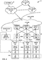
- FIG. 2 is a block diagram illustrating an example multi-cloud network having a data center in which examples of the techniques described herein may be implemented.
- FIG. 2 illustrates data centers 32A-32X, which house servers that form respective ones of VCEs 12.
- data center 32A houses servers 34A-34N that may be configured to provide the infrastructure for VCE 12A.
- the other data centers 34 may be substantially similar to data center 32A, but may house servers for other VCEs 12. Also, one of data centers 32 may house servers for multiple VCEs 12.
- data centers 32A-32X are interconnected with one another and with customer networks associated with customers 46 via a service provider network 33.
- each data center 32A provides an operating environment for applications and services for customers 46 coupled to the data center by service provider network 33.
- Data centers 32 may, for example, host infrastructure equipment, such as networking and storage systems, redundant power supplies, and environmental controls.
- Service provider network 33 may be coupled to one or more networks administered by other providers, and may thus form part of a large-scale public network infrastructure, e.g., the Internet.
- each data centers 32 may represent one of many geographically distributed network data centers. As illustrated in the example of FIG. 2 , each of data centers 32 may represent a facility that provides network services for customers 46. Customers 46 may be collective categories such as enterprises and governments or individuals. For example, a network data center may host a virtual computing environment (e.g., cloud) that provides web services for several enterprises and end users. Other example services may include data storage, virtual private networks, traffic engineering, file service, data mining, scientific- or super-computing, and so on. In some examples, each of data centers 32 may be individual network servers, network peers, or otherwise.
- each of data centers 32 includes a set of storage systems and application servers 34A-34N (herein, “servers 34") interconnected via high-speed switch fabric 35 provided by one or more tiers of physical network switches and routers.
- Switch fabric 35 is provided by a set of interconnected top-of-rack (TOR) switches 40A-40N (collectively, “TOR switches 40") coupled to a distribution layer of chassis switches 42A-42Y (collectively, “chassis switches 42").
- each of data centers 32 may also include, for example, one or more non-edge switches, routers, hubs, gateways, security devices such as firewalls, intrusion detection, and/or intrusion prevention devices, servers, computer terminals, laptops, printers, databases, wireless mobile devices such as cellular phones or personal digital assistants, wireless access points, bridges, cable modems, application accelerators, or other network devices.
- security devices such as firewalls, intrusion detection, and/or intrusion prevention devices
- servers computer terminals, laptops, printers, databases
- wireless mobile devices such as cellular phones or personal digital assistants, wireless access points, bridges, cable modems, application accelerators, or other network devices.
- TOR switches 40 and chassis switches 42 provide servers 34 with redundant (multi-homed) connectivity to IP fabric 44 and service provider network 33.
- Chassis switches 42 aggregate traffic flows and provides high-speed connectivity between TOR switches 40.
- TOR switches 40 may be network devices that provide layer two (e.g., MAC) and/or layer 3 (e.g., IP) routing and/or switching functionality.
- TOR switches 40 and chassis switches 42 may each include one or more processors and a memory, and that are capable of executing one or more software processes.
- Chassis switches 42 are coupled to IP fabric 44, which performs layer 3 routing to route network traffic between data centers 32 and customers 46 by service provider network 33.
- data center 32A is configured to provide the infrastructure for VCE 12A.
- servers 34A-34N may be configured to execute virtualized machines (VMs) to support the operation of VCE 12A.
- controller 14 is part of VCE 12A. Accordingly, servers 34A-34N may be configured to support the operation of controller 14.
- servers 34A and 34B execute VMs 50A and 50B.
- VMs 50A and 50B together provide a virtualized machine on which controller 14 can execute and perform the example operations of controller 14 described in this disclosure (e.g., provide a centralized controller to ensure proper route propagation, securing, and application deployment on the VCEs with a single pane of glass interface).
- Servers 34A, 34B, and 34N execute VMs 54A, 54B, and 54C.
- VMs 54A, 54B, and 54C together provide a virtualized machine on which connect gateway router 18A executes and performs the example operations of connect gateway router 18A described in this disclosure (e.g., form a logical endpoint within a logical tunnel mesh for VCE 12A).
- VM 52 may provide a virtualized machine on which applications that are to execute within VCE 12A execute.
- VCE 12A may provide computation resources to offload computationally complex tasks from a personal computer.
- VM 52 is the platform on which the applications execute to perform the tasks offloaded from the personal computer.
- VMs 50A, 50B, 52, 54A, 54B, and 54C are illustrated merely to assist with understanding and should not be considered as limiting.
- virtualized network controller 36 may be configured to spin up and spin down virtual machines across or within servers 34 as needed to support the operations of controller 14, connect gateway router 18A, and VCE 12A.
- controller 14 may be configured to determine resources within data center 32A that are to be utilized (e.g., how many VMs are spun up or spun down) for VCE 12A.
- controller 14 may be configured to determine resources within the other data centers 32 that are to be utilized (e.g., how many VMs are spun up or spun down) for the other VCEs 12.
- VMs 50A, 50B, 52, 54A, 54B, and 54C execute on processing circuitry of respective servers 34A, 34B, and 34N.
- An example of processing circuitry on which VMs 50A, 50B, 52, 54A, 54B, and 54C execute is illustrated in more detail with respect to FIG. 13 .
- Virtual network controller 36 provides a logically and in some cases physically centralized controller for facilitating operation of one or more virtual networks within each of data centers 32, such as data center 32A.
- virtual network controller 36 may operate in response to configuration input received from network administrator 38.
- administrator 38 may be tasked with providing configuration information for controller 14 so that controller 14 can perform the example operations described in this disclosure.
- Administrator 38 may represent an operator, developer, or application deployment specialist that uses a common interface to create and deploy virtual computing environment topologies to virtualized network controller 36 and controller 14 for provisioning within the computing infrastructure.
- the traffic between any two network devices can traverse the physical network using many different paths.
- a packet flow (or "flow") can be defined by the five values used in a header of a packet, or "five-tuple," i.e., the protocol, source IP address, destination IP address, source port and destination port that are used to route packets through the physical network.
- the protocol specifies the communications protocol, such as TCP or UDP, and source port and destination port refer to source and destination ports of the connection.
- the flow within data center 32A is one example of a flow.
- Another example of a flow is the flow of data between VCEs 12.
- examples of flow between VCEs 12 include UDP encapsulated ESP packets.
- a set of one or more packet data units (PDUs) that include a packet header specifying a particular five-tuple represent a flow.
- Flows may be broadly classified using any parameter of a PDU, such as source and destination data link (e.g., MAC) and network (e.g., IP) addresses, a Virtual Local Area Network (VLAN) tag, transport layer information, a Multiprotocol Label Switching (MPLS) or Generalized MPLS (GMPLS) label, and an ingress port of a network device receiving the flow.
- source and destination data link e.g., MAC
- network e.g., IP
- VLAN Virtual Local Area Network
- MPLS Multiprotocol Label Switching
- GPLS Generalized MPLS
- a flow may be all PDUs transmitted in a Transmission Control Protocol (TCP) connection, all PDUs sourced by a particular MAC address or IP address, all PDUs having the same VLAN tag, or all PDUs received at the same switch port.
- a flow may be additionally or alternatively defined by an Application Identifier (AppID) that is determined by a virtual router agent or other entity that identifies, e.g., using a port and protocol list or deep packet inspection (DPI), a type of service or application associated with the flow in that the flow transports application data for the type of service or application.
- AppID Application Identifier
- DPI deep packet inspection
- FIG. 2 illustrates an example of a VCE 12A in a multi-cloud network 10.
- a single SDN controller 14 is configured to establish the logical tunnel mesh to interconnect the plurality of VCEs 12 in the multi-cloud network via respective connect gateway routers 18.
- SDN controller 14 is also configured to advertise the one or more logical tunnels to VCEs 12.
- data center 32A includes one or more virtual machines executing on one or more servers, such that the one or more virtual machines form an infrastructure for VCE 12A, and at least one of the virtual machines executes a connect gateway router 18A to form the logical endpoint for VCE 12A.
- FIG. 1 illustrates an example of a VCE 12A in a multi-cloud network 10.
- FIG. 2 illustrates an example of a VCE 12A in a multi-cloud network 10.
- a single SDN controller 14 is configured to establish the logical tunnel mesh to interconnect the plurality of VCEs 12 in the multi-cloud network via respective connect gateway routers 18.
- SDN controller 14 is also configured
- VM 52 form on server 34N forms an infrastructure for VCE 12A
- FIG. 2 illustrates one example of data center 32A
- other data centers may be substantially similar, but may not execute an instance of controller 14.
- a set of one or more virtual machines executing on second set of one or more servers in data center 32A form an infrastructure for VCE 12B.
- at least one of the set of one or more virtual machines executes connect gateway router 18B to form the logical endpoint for VCE 12B.
- controller 14 is configured to establish a logical tunnel (e.g., tunnel 28A) of the logical tunnel mesh that interconnects the connect gateway router 18A and connect gateway router 18B.
- a logical tunnel e.g., tunnel 28A
- FIG. 3 is a block diagram illustrating an example multi-cloud network configured to communicate in accordance with one or more example techniques described in this disclosure.
- FIG. 3 illustrates data centers 60, 62, 64, 66, and 68, and each may host one or more VCEs.
- controller 14 (identified as contr-prem2 in FIG. 3 ) executes on servers within data center 60.
- each of data centers 60, 62, 64, 66, and 68 support a public LAN that interconnect the data centers via the Internet.
- Each of the respective public LANs are coupled to respective connect gateway routers.
- the public LAN of data center 60 is connected to a connect gateway router (identified as gw1-prem2), the public LAN of data center 62 is connect to two connect gateway routers (identified as gw1-prem1 and gw2-prem1), and so forth.
- each connect gateway router is associated with a logical endpoint within a logical tunnel mesh for respective VCEs.
- the data centers may be connected with SSL tunnels (e.g., Hybrid Cloud with SSL tunnel) or IPSec tunnels.
- contr-prem2 may be configured to establish the logical tunnel mesh shown in FIG. 3 that interconnects the VCEs via the Internet, allowing one administrator to ensure proper route propagation, securing, and application deployment on the VCEs with a single pane of glass interface.
- an administrator may need to execute an application that provides a graphical user interface (GUI) or even a text interface to access the controls of contr-prem2, and with this one interface, the administrator can establish the tunnel mesh (e.g., using IPSec sessions) and advertise the routes (e.g., using BGP).
- GUI graphical user interface
- the administrator can establish security policies to ensure desired level of security.
- FIG. 4 is a block diagram illustrating an example multi-cloud network configured to communicate in accordance with one or more example techniques described in this disclosure.
- FIG. 4 illustrates an example of a IPSec full mesh so that gateway controllers are different premises can communicate with other another.
- premises 1 includes two connect gateway routers (GW1 and GW2) to support two VCEs
- premises 2 includes one connect gateway router (GW1) to support one VCE
- premises 3 includes two gateway routers (GW1 and GW2) to support two VCEs.
- FIG. 4 also illustrates an OpenVPN full mesh that connects to different sites having their own respective connect gateway routers.
- controller 14 may be configured to establish the example IPSec full mesh illustrated in FIG. 4 , and possibility also the OpenVPN full mesh, where an administrator can use the single pane of glass to control controller 14 to establish the IPSec full mesh and the Open VPN mesh.
- the data centers may be connected with SSL tunnels or IPSec tunnels (e.g., Hybrid Cloud with IPSec ESP tunnel).
- FIG. 5 is a block diagram illustrating an example connect gateway router 18A in accordance with one or more example techniques described in this disclosure.
- the IPSec session module IPSec Crypto
- IKEv2 key exchange modules
- the example techniques are not so limited, and these components may be part of controller 14.
- the example illustrated in FIG. 5 is merely meant to provide one example, and should not be considered limiting.
- FIG. 6 is a flowchart illustrating an example method of operation in accordance with one or more example techniques described in this disclosure.
- FIG. 6 describes an example method in a system that includes a plurality of virtual computing environments (e.g., VCEs 12) in multi-cloud network 10.
- VCEs 12 virtual computing environments
- a single software-defined networking (SDN) controller 12 is configured to establish a logical mesh to interconnect the plurality of VCEs 12 in multi-cloud network 10 via respective connect gateway routers 18 (100).
- SDN software-defined networking
- VCEs 12 are VCEs that support one tenant.
- a tenant utilizes two or more of VCEs 12 to perform operations that are well suited to be performed in a cloud infrastructure.
- an administrator for the tenant would have needed to setup tunnels separately at each of the locations of VCEs 12 so that servers on which the applications for the tenant are executing can communicate with one another.
- the administrator is able to establish tunnels 28 between VCEs 12 with a single pane of glass.
- Connect gateway routers 18 may each form as a logical endpoint within the logical tunnel mesh for respective VCEs 12.
- controller 14 may be configured to determine one or more logical tunnels (e.g., tunnel 28A) from the logical tunnel mesh to establish one or more communication links between a first VCE (e.g., VCE 12A) and a second VCE (e.g., VCE 12B).
- a first set of one or more virtual machines execute on a first set of one or more servers, and the first set of one or more virtual machines form an infrastructure for the first VCE. Also, at least one of the first set of one or more virtual machines executes a connect gateway router to form the logical endpoint for the first VCE.
- a second set of one or more virtual machines executes on a second set of one or more servers. The second set of one or more virtual machines form an infrastructure for the second VCE, and at least one of the second set of one or more virtual machines executes a second connect gateway router to form the logical endpoint for the second VCE.
- controller 14 is configured to establish a logical tunnel of the logical tunnel mesh that interconnects the first connect gateway router and the second connect gateway router.
- Controller 14 may be configured to advertise the one or more logical tunnels to the first VCE and the second VCE. In this way, with a single pane of glass (e.g., with one interface to the single controller 14), an administrator may be able to configure communication between different VCEs to allow for proper route propagation that is secure, rather than establish communication links on a VCE-by-VCE or data center-by-data center basis.
- at least one of the VCEs includes a key server configured to generate certificates to be deployed to one or more of the VCEs for encrypted communication. Controller 14 may be configured to cause the key server to generate certificates during the establishing of the logical tunnel mesh.
- controller 14 is configured to establish Internet Protocol Security (IPSec) sessions between the connect gateway routers 18 of respective VCEs 12. Also, in some examples, to advertise the one or more logical tunnels, controller 14 may be configured to advertise the one or more logical tunnels via Border Gateway Protocol (BGP).
- IPSec Internet Protocol Security
- BGP Border Gateway Protocol
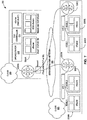
- FIG. 7 is a block diagram illustrating an example network 200 including a controller 214 for directing information within network 200, according to techniques described in this disclosure.
- Service provider network 206 may be an example of service provider network 33 of FIG. 2 .
- Cloud 210 may be an example of data center 32A of FIG. 2 .
- Controller 214 and orchestrator 212 may implement an overall controller, such as controller 14 of FIG. 1 .
- Cloud 220 may be an example of any one of data centers 32B-32X of FIG. 2 .
- Controller 212 provides a logically and in some cases physically centralized controller for facilitating operation of one or more virtual networks within each of cloud 210 and cloud 220, such as VPC 1 of cloud 220, in accordance with one or more embodiments of this disclosure.
- controller 212 may operate in response to configuration input received from a transformer.
- orchestrator 212 manages functions of cloud 210 such as compute, storage, networking, and application resources. For example, orchestrator 212 may create a virtual network for a tenant within cloud 210 or across data centers. Orchestrator 212 may attach virtual machines (VMs) to a tenant's virtual network. Orchestrator 212 may connect a tenant's virtual network to an external network, e.g. the service provider network 206 or cloud 220. Orchestrator 212 may implement a security policy across a group of VMs or to the boundary of a tenant's network. Orchestrator 212 may deploy a network service (e.g. a load balancer) in a tenant's virtual network.
- a network service e.g. a load balancer
- controller 214 maintains routing, networking, and configuration information within a state database.
- orchestrator 212 uses Kubernetes for automating deployment, scaling, and management of containerized applications.
- orchestrator 212 may use Kubernetes to deploy containers to any one of servers 226A-226E (collectively, "servers 226") via controller 214.
- the containers may include Docker containers.
- Orchestrator 212 may output instructions to controller 214 to deploy containers to servers 226 via gateway 230.
- Groups of servers 226 may be interconnected via a high-speed switch fabric (not shown) provided by one or more tiers of physical network switches and routers.
- the switch fabric is provided by a set of interconnected top-of-rack (TOR) switches (not shown) coupled to a distribution layer of chassis switches (not shown).
- TOR top-of-rack
- each of cloud 210 and cloud 220 may also include, for example, one or more non-edge switches, routers, hubs, gateways, security devices such as firewalls, intrusion detection, and/or intrusion prevention devices, servers, computer terminals, laptops, printers, databases, wireless mobile devices such as cellular phones or personal digital assistants, wireless access points, bridges, cable modems, application accelerators, or other network devices.
- Each server of servers 226 may include at least one virtual router and at least one container or virtual machine.
- Gateway 230A-230C may provide virtual private network (VPN) services for providing connectivity over a wide area network (WAN). Tenant isolation may be performed for a tenant application workload using a standards based VPN. Gateway 230 may provide the same security posture for each data center 110A using a security policy framework. Additionally, gateway 230 may provide resiliency across availability zones in public and private cloud environments. Gateway 230 may be configured for role-based access control (RBAC) and integration with active directory/ lightweight directory access protocol (AD/LDAP). In some examples, gateway 230 may enable controller 202 to transport packets, including containers, between one or more data centers. Gateway 230 may use an encrypted connection (e.g., IPSec with Nat-t or SSL) to exchange information between gateway portals 230A, 230B, and 230C.
- VPN virtual private network
- WAN wide area network
- IP virtual private network
- Gateway 230 may provide the same security posture for each data center 110A using a security policy framework. Additionally, gateway 230 may provide resiliency across availability zones in
- FIG. 8 is a block diagram illustrating an example multi-cloud computing infrastructure 300 including a controller 302 (which is an example of controller 14), a public cloud 304, a private cloud 306, and a bare-metal server system 308, according to techniques described in this disclosure.
- controller 302 may provision the public cloud 304, the private cloud 306, and the bare-metal server system 308 by mapping software to respective nodes. Provisioning includes a process of preparing and equipping a network, thus allowing the network to provide new services.
- the provisioning may include using controller 302 to deploy containers to nodes of any one of the public cloud 304, the private cloud 306, and the bare-metal server system 308.
- the provisioning may include using controller 302 to enable security (e.g., activate or program firewalls) on of any one of the public cloud 304, the private cloud 306, and the bare-metal server system 308. Additionally, controller 302 may monitor and manage each of the public cloud 304, the private cloud 306, and the bare-metal server system 308. For example, if the network 300 receives instructions to perform a new task, controller 302 may provision network 300 to perform the new task by deploying new software and creating new infrastructure configurations in at least one of the public cloud 304, the private cloud 306, and the bare-metal server system 308. Controller 302 may represent an example instance of controller 14 of FIG. 1 .
- FIG. 9 is a conceptual diagram illustrating another example multi-cloud computing infrastructure 400 managed using a controller, according to techniques described in this disclosure.
- Controller 402 which is an example of controller 14, of network 400 may deploy software to data centers including server 410, VPC 420, VPC 430, and bare-metal server system 440.
- Server 410 may include one or more virtual machines and one or more containers.
- VPC 420, VPC 430, and bare-metal server system 440 may include one or more virtual machines and one or more containers.
- controller 402 may deploy containers to build computing infrastructures in the data centers.
- Controller 402 may receive instructions from a transformer (not pictured).
- the instructions may be indicative of data (e.g., containers, objects, applications, or the like) to be deployed to each respective data center to achieve a desired virtual computing environment.
- the data centers may output information indicative of a current state of network structure to controller 402.
- the transformer may be configured to use the current state of the virtual computing environment output by the data centers and the desired state of the virtual computing environment to produce templates.
- the templates may be applied by controller 400 to build the plurality of computing infrastructures of the data centers.
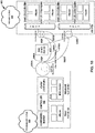
- FIG. 10 is a block diagram illustrating another example controller for directing containers within a multi-cloud infrastructure 800, according to techniques described in this disclosure.
- the infrastructure 800 of FIG. 10 includes on-premises cloud 810 and private cloud 820.
- Controller 812 which is an example of controller 14, may distribute data (e.g., packets, objects, containers, applications, or the like) via gateway portals 830A-830C (collectively, gateway 830, which may be examples of connect gateway routers 18).
- gateway portals of gateway 830 may be connected using a group of pathways.
- gateway portal 830A and gateway portal 830B may be connected by a border gateway protocol (BGP) 840A and an Internet Protocol Security (IPSec) Encrypted Overlay channel 850A.
- BGP border gateway protocol
- IPSec Internet Protocol Security
- BGP is a standardized exterior gateway protocol for exchanging routing and reachability information between servers.
- a device executing BGP may transmit information required to route packets through one or more routers (e.g., the vRouters of infrastructure 800).
- BGP sessions may or may not be encrypted. Consequently, it may be beneficial for gateway 830 to include secure channels for transmitting routing information between gateway portals.
- IPSec encrypted overlay channels 850 may connect gateway portals such that routing information may be transmitted in a secure manner.
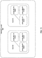
- FIG. 11 is a block diagram illustrating an example private cloud 900 including at least one region and at least one availability zone, according to techniques described in this disclosure.
- Each region of the at least one region includes a geographical area with a collection of availability zones mapped to physical data centers in the respective region. Every region of the at least one region is physically isolated from and independent of every other region of the at least one region in terms of location, power, water supply, etc.
- An availability zone is a logical data center in a region available for use by customer of private cloud 900.
- Each availability zone in a region has redundant and separate power, networking and connectivity to reduce the likelihood of two availability zones failing simultaneously.
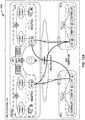
- FIGS. 12A-12C are block diagrams illustrating an example network 1000 including at least one gateway portal, according to techniques described in this disclosure.
- Gateway portals may be located within each availability zone of network 1000.
- controllers configured for building and monitoring computing infrastructures within availability zones including gateway portals.
- the gateway portals of the availability zones may be configured to communicate with the gateway portals of the controllers via an encrypted channel (an IPSec, a Secure Sockets Layer (SSL), or a network address translator traversal (Nat-t)).
- an encrypted channel an IPSec, a Secure Sockets Layer (SSL), or a network address translator traversal (Nat-t)
- tenant devices within an availability zone are configured to transmit and receive information (e.g., packets, containers, or the like) with the controllers and tenant devices in another availability zone (e.g., AZ-2).
- information e.g., packets, containers, or the like
- another availability zone e.g., AZ-2
- gateway portals may enable tenant devices within AZ-2 to exchange information with the controllers of DC-1 and DC-2.
- failures of availability zones may be handled by the gateway. For example, during an instance failure, gateway portals are deployed in active - standby pairs within each availability zone and DC-1 and DC-2. Gateway instance failures will have tunnel routes and next hops advertised to point to the current active gateway portal. In cases where both the gateway instances fail in an availability zone (e.g., AZ-1), then the routes to the gateway instances will be directed via the AZ-2 within the VPC.
- an availability zone e.g., AZ-1
- FIG. 13 is a block diagram of an example computing device, according to techniques described in this disclosure.
- Computing device 1300 may be an example instance of servers 34 of FIG. 2 for a cloud computing infrastructure.
- Computing device 1300 may represent one or more real or virtual servers configured to perform operations for an SDN controller 14.
- SDN controller 14 may be a logically centralized, but physically distributed controller. Hence, SDN controller 14 may execute across one or more computing devices, and computing device 1300 is one example of such computing devices.
- Computing device 1300 includes in this example, a bus 1342 coupling hardware components of a computing device 1300 hardware environment.
- Bus 1342 couples network interface card (NIC) 1330, storage disk 1346, and one or more microprocessors 1310 (hereinafter, "microprocessor 1310").
- a frontside bus may in some cases couple microprocessor 1310 and memory device 1344.
- bus 1342 may couple memory device 1344, microprocessor 1310, and NIC 1330.
- Bus 1342 may represent a Peripheral Component Interface (PCI) express (PCIe) bus.
- PCIe Peripheral Component Interface
- PCIe Peripheral Component Interface
- a direct memory access (DMA) controller may control DMA transfers among components coupled to bus 1342.
- components coupled to bus 1342 control DMA transfers among components coupled to bus 1342.
- Microprocessor 1310 may include one or more processors each including an independent execution unit to perform instructions that conform to an instruction set architecture, the instructions stored to storage media.
- Execution units may be implemented as separate integrated circuits (ICs) or may be combined within one or more multi-core processors (or "many-core" processors) that are each implemented using a single IC (i.e., a chip multiprocessor).
- ICs integrated circuits
- many-core multi-core processors
- microprocessor 1310 is an example of processing circuitry on which SDN controller 14 executes.
- Disk 1346 represents computer readable storage media that includes volatile and/or non-volatile, removable and/or non-removable media implemented in any method or technology for storage of information such as processor-readable instructions, data structures, program modules, or other data.
- Computer readable storage media includes, but is not limited to, random access memory (RAM), read-only memory (ROM), EEPROM, Flash memory, CD-ROM, digital versatile discs (DVD) or other optical storage, magnetic cassettes, magnetic tape, magnetic disk storage or other magnetic storage devices, or any other medium that can be used to store the desired information and that can be accessed by microprocessor 1310.
- Main memory 1344 includes one or more computer-readable storage media, which may include random-access memory (RAM) such as various forms of dynamic RAM (DRAM), e.g., DDR2/DDR3 SDRAM, or static RAM (SRAM), flash memory, or any other form of fixed or removable storage medium that can be used to carry or store desired program code and program data in the form of instructions or data structures and that can be accessed by a computer.
- RAM random-access memory
- DRAM dynamic RAM
- SRAM static RAM
- flash memory or any other form of fixed or removable storage medium that can be used to carry or store desired program code and program data in the form of instructions or data structures and that can be accessed by a computer.
- Main memory 1344 provides a physical address space composed of addressable memory locations.
- Network interface card (NIC) 1330 includes one or more interfaces 1332 configured to exchange packets using links of an underlying physical network. Interfaces 1332 may include a port interface card having one or more network ports. NIC 1330 may also include an on-card memory to, e.g., store packet data. Direct memory access transfers between the NIC 1330 and other devices coupled to bus 1342 may read/write from/to the NIC memory.
- Memory 1344, NIC 1330, storage disk 1346, and microprocessor 1310 may provide an operating environment for a software stack that includes an operating system kernel 1314 executing in kernel space.
- Kernel 1314 may represent, for example, a Linux, Berkeley Software Distribution (BSD), another Unix-variant kernel, or a Windows server operating system kernel, available from Microsoft Corp.
- the operating system may execute a hypervisor and one or more virtual machines managed by hypervisor.
- Example hypervisors include Kernel-based Virtual Machine (KVM) for the Linux kernel, Xen, ESXi available from VMware, Windows Hyper-V available from Microsoft, and other open-source and proprietary hypervisors.
- the term hypervisor can encompass a virtual machine manager (VMM).
- An operating system that includes kernel 1314 provides an execution environment for one or more processes in a user space.
- Computing device 1300 may be coupled to a physical network switch fabric that includes an overlay network that extends switch fabric from physical switches to software or "virtual" routers of physical servers coupled to the switch fabric, such as virtual router 48 of FIG. 2 .
- Computing device 1300 provides an operating environment for SDN application 1348, which may perform operations described above with respect to other instances of SDN controllers described herein.
- SDN application 1348 represents one or more applications, and SDN application 1348 may execute one or more protocols, such as Simple Network Management Protocol (SNMP) and Netconf.
- SNMP Simple Network Management Protocol
- Netconf Netconf.
- SDN application 1348 may use the one or more protocols to, e.g., establish tunnels 18 and BGP peering sessions over tunnels between connect gateway routers.
- Computer-readable media may include computer-readable storage media, which corresponds to a tangible medium such as data storage media, or communication media including any medium that facilitates transfer of a computer program from one place to another (e.g., pursuant to a communication protocol).
- computer-readable media generally may correspond to (1) tangible computer-readable storage media, which is non-transitory or (2) a communication medium such as a signal or carrier wave.
- Data storage media may be any available media that can be accessed by one or more computers or one or more processors to retrieve instructions, code and/or data structures for implementation of the techniques described in this disclosure.
- a computer program product may include a computer-readable medium.
- such computer-readable storage media can include RAM, ROM, EEPROM, CD-ROM or other optical disk storage, magnetic disk storage, or other magnetic storage devices, flash memory, or any other medium that can be used to store desired program code in the form of instructions or data structures and that can be accessed by a computer.
- any connection is properly termed a computer-readable medium.
- a computer-readable medium For example, if instructions are transmitted from a website, server, or other remote source using a coaxial cable, fiber optic cable, twisted pair, digital subscriber line (DSL), or wireless technologies such as infrared, radio, and microwave, then the coaxial cable, fiber optic cable, twisted pair, DSL, or wireless technologies such as infrared, radio, and microwave are included in the definition of medium.
- DSL digital subscriber line
- Disk and disc includes compact disc (CD), laser disc, optical disc, digital versatile disc (DVD), floppy disk and Blu-ray disc, where disks usually reproduce data magnetically, while discs reproduce data optically with lasers. Combinations of the above should also be included within the scope of computer-readable media.
- processors such as one or more digital signal processors (DSPs), general purpose microprocessors, application specific integrated circuits (ASICs), field programmable logic arrays (FPGAs), or other equivalent integrated or discrete logic circuitry.
- DSPs digital signal processors
- ASICs application specific integrated circuits
- FPGAs field programmable logic arrays
- processors may each refer to any of the foregoing structure or any other structure suitable for implementation of the techniques described.
- the functionality described may be provided within dedicated hardware and/or software modules. Also, the techniques could be fully implemented in one or more circuits or logic elements.
- the techniques of this disclosure may be implemented in a wide variety of devices or apparatuses, including a wireless handset, a mobile or non-mobile computing device, a wearable or non-wearable computing device, an integrated circuit (IC) or a set of ICs (e.g., a chip set).
- IC integrated circuit
- Various components, modules, or units are described in this disclosure to emphasize functional aspects of devices configured to perform the disclosed techniques, but do not necessarily require realization by different hardware units. Rather, as described above, various units may be combined in a hardware unit or provided by a collection of interoperating hardware units, including one or more processors as described above, in conjunction with suitable software and/or firmware.
- a single software-defined network (SDN) controller establishes tunnels and controls communication on these tunnels between a plurality of virtual computing environments (VCEs).
- the SDN controller establishes the logical tunnel mesh to interconnect the plurality of VCEs in the multi-cloud network via respective connect gateway routers.
- the SDN controller is configured to determine one or more logical tunnels from the logical tunnel mesh to establish one or more communication links between a first VCE and a second VCE of the plurality of VCEs in the multi-cloud network.
- the SDN controller is configured to advertise the one or more logical tunnels to the first VCE and the second VCE.
Landscapes
- Engineering & Computer Science (AREA)
- Computer Networks & Wireless Communication (AREA)
- Signal Processing (AREA)
- Theoretical Computer Science (AREA)
- Computer Security & Cryptography (AREA)
- Software Systems (AREA)
- Computing Systems (AREA)
- Physics & Mathematics (AREA)
- General Engineering & Computer Science (AREA)
- General Physics & Mathematics (AREA)
- Data Exchanges In Wide-Area Networks (AREA)
Abstract
Description
- This application claims the benefit of
U.S. Patent Application no. 16/144,711, filed on September 27, 2018 U.S. Provisional Patent Application No. 62/718,765, filed on August 14, 2018 - The disclosure relates to computer networking, and more particularly, computer networking in a multi-cloud environment.
- In a typical cloud data center environment, there is a large collection of interconnected servers that provide computing and/or storage capacity to run various applications. For example, a data center may comprise a facility that hosts applications and services for subscribers, i.e., customers of data center. The data center may, for example, host all of the infrastructure equipment, such as networking and storage systems, redundant power supplies, and environmental controls. In a typical data center, clusters of storage systems and application servers are interconnected via high-speed switch fabric provided by one or more tiers of physical network switches and routers. More sophisticated data centers provide infrastructure spread throughout the world with subscriber support equipment located in various physical hosting facilities.
- Virtual machines are a virtualization scheme based on machine-level virtualization. Virtual machines include a guest operating system that runs on a hypervisor of the host computing device to emulate the hardware of a computer to provide a new computer environment for executing applications.
- Containerization is a virtualization scheme based on operation system-level virtualization. Containers are light-weight and portable execution environments for applications that are isolated from one another and from the host. Because containers are not tightly-coupled to the host hardware computing environment, an application can be tied to a container image and executed as a single light-weight package on any host or virtual host that supports the underlying container architecture. As such, containers address the problem of how to make software work in different computing environments. Containers offer the promise of running consistently from one computing environment to another, virtual or physical.
- With containers' inherently lightweight nature, a single host can support many more container instances than traditional virtual machines (VMs). Often short-lived, containers can be created and moved more efficiently than VMs, and they can also be managed as groups of logically-related elements (sometimes referred to as "pods" for some orchestration platforms, e.g., Kubernetes). These container characteristics impact the requirements for container networking solutions: the network should be agile and scalable. VMs, containers, and bare metal servers may need to coexist in the same cloud environment, with communication enabled among the diverse deployments of applications. The container network should also be agnostic to work with the multiple types of orchestration platforms that are used to deploy containerized applications.
- A cloud computing infrastructure that manages deployment and infrastructure for application execution may involve two main roles: (1) orchestration-for automating deployment, scaling, and operations of applications across clusters of hosts and providing computing infrastructure, which may include container-centric computing infrastructure; and (2) network management-for creating virtual networks in the network infrastructure to enable communication among applications running on virtual execution environments, such as containers or VMs, as well as among applications running on legacy (e.g., physical) environments. Software-defined networking contributes to network management.
- Multi-cloud environment refers to the use of multiple clouds for computing and storage services. An enterprise may utilize an on-premise computing and/or storage service (e.g., on-premises cloud), and one or more off-premise clouds such as those hosted by third-party providers. Examples of the clouds include private, public, or hybrid public/private clouds that allow for ease of scalability while allowing different levels of control and security. An enterprise may utilize one or more of private, public, or hybrid public/private clouds based on the types of applications that are executed and other needs of the enterprise.
- In general, the disclosure describes examples where a single software-defined network (SDN) controller, executing on processing circuitry, establishes tunnels and controls communication on these tunnels between a plurality of virtual computing environments (VCEs). A VCE is provisioned in virtualized computing infrastructure, such as a public, private, or hybrid cloud. A virtual private cloud (VPC) is an example of VCE. Each of the VCEs supports one or more tenants or customers (e.g., enterprises), and in some examples, the VCEs need to communicate with one another to support various functions defined by the tenants. In some examples, a first VCE (e.g., private cloud) and a second VCE (e.g., public cloud) both support the same tenant, and the first and second VCEs may need to communicate with one another.
- In some existing techniques, each VCE administrator would need to setup policies to establish communication tunnels between the different VCEs. Such separate management of VCEs to establish communication tunnels resulted in delays or errors due to the complications associated with ensuring proper route propagation, security, and application deployment, as a few examples. The techniques of this disclosure may provide one or more technical advantages. For example, the techniques provide for centralized control for communication between VCEs with a single controller, allowing one administrator to ensure proper route propagation, securing, and application deployment on the VCEs using a common interface. The common controller for route control within the VCEs and advertising among the VCEs may enable seamless and secure communications among multiple VCEs, in some cases distributed among on-premise and off-premise / public computing infrastructures. In this way, the multiple VCEs may appear to the operator or developer as a single compute fabric for distributed application execution.
- In one example, the disclosure describes a system comprising a plurality of virtual computing environments (VCEs) in a multi-cloud network, a plurality of connect gateway routers, wherein each connect gateway router is associated with a logical endpoint within a logical tunnel mesh for respective VCEs, and a single software-defined networking (SDN) controller, executing on processing circuitry. The SDN controller is configured to establish the logical tunnel mesh to interconnect the plurality of VCEs in the multi-cloud network via respective connect gateway routers. To establish the logical tunnel mesh, the SDN controller is configured to determine one or more logical tunnels from the logical tunnel mesh to establish one or more communication links between a first VCE and a second VCE of the plurality of VCEs in the multi-cloud network. The SDN controller is also configured to advertise the one or more logical tunnels to the first VCE and the second VCE.
- In one example, the disclosure describes a method comprising establishing, with a single software-defined networking (SDN) controller executing on processing circuitry, a logical tunnel mesh to interconnect a plurality of virtual computing environments (VCEs) in a multi-cloud network via respective connect gateway routers. Each connect gateway router is associated with a logical endpoint within a logical tunnel mesh for respective VCEs, and establishing the logical tunnel mesh comprises determining one or more logical tunnels from the logical tunnel mesh to establish one or more communication links between a first VCE and a second VCE of the plurality of VCEs in the multi-cloud network. The method also includes advertising the one or more logical tunnels to the first VCE and the second VCE.
- In one example, the disclosure describes a computer-readable storage medium storing instructions thereon that when executed cause one or more processors, via execution of a single software-defined networking (SDN) controller, to establish, by execution of the SDN controller, a logical tunnel mesh to interconnect a plurality of virtual computing environments (VCEs) in a multi-cloud network via respective connect gateway routers. Each connect gateway router is associated with a logical endpoint within a logical tunnel mesh for respective VCEs. The instructions that cause the one or more processors, via execution of the SDN controller, to establish the logical tunnel mesh comprise instructions that cause the one or more processors, via execution of the SDN controller, to determine one or more logical tunnels from the logical tunnel mesh to establish one or more communication links between a first VCE and a second VCE of the plurality of VCEs in the multi-cloud network. The instruction cause the one or more processors, via execution of the SDN controller, to advertise the one or more logical tunnels to the first VCE and the second VCE.
- The details of one or more examples are set forth in the accompanying drawings and the description below. Other features, objects, and advantages will be apparent from the description and drawings, and from the claims.
-
-
FIG. 1 is a block diagram illustrating an example multi-cloud network configured to communicate in accordance with one or more example techniques described in this disclosure. -
FIG. 2 is a block diagram illustrating an example multi-cloud network having a data center in which examples of the techniques described herein may be implemented. -
FIG. 3 is a block diagram illustrating an example multi-cloud network configured to communicate in accordance with one or more example techniques described in this disclosure. -
FIG. 4 is a block diagram illustrating an example multi-cloud network configured to communicate in accordance with one or more example techniques described in this disclosure. -
FIG. 5 is a block diagram illustrating an example connect gateway router in accordance with one or more example techniques described in this disclosure. -
FIG. 6 is a flowchart illustrating an example method of operation in accordance with one or more example techniques described in this disclosure. -
FIG. 7 is a block diagram illustrating an example network including a controller for directing information within network, according to techniques described in this disclosure. -
FIG. 8 is a block diagram illustrating another example network including a controller, a public cloud, a private cloud, and a bare-metal server system, according to techniques described in this disclosure. -
FIG. 9 is a conceptual diagram illustrating another example multi-cloud computing infrastructure managed using a controller, according to techniques described in this disclosure. -
FIG. 10 is a block diagram illustrating another example controller for directing containers within a network, according to techniques described in this disclosure. -
FIG. 11 is a block diagram illustrating an example private cloud including at least one region and at least one availability zone, according to techniques described in this disclosure. -
FIGS. 12A-12C are block diagrams illustrating an example system including at least one gateway unit, according to techniques described in this disclosure. -
FIG. 13 is a block diagram of an example computing device, according to techniques described in this disclosure. -
FIG. 1 is a block diagram illustrating an example multi-cloud network configured to communicate in accordance with one or more example techniques described in this disclosure. As illustrated,multi-cloud network 10 includes virtual computing environments (VCEs) 12A-12C (collectively VCEs 12). VCEs 12 may be provisioned within a public, private, hybrid, or other "cloud" that provide storage and compute for various applications. A cloud may refer to computing infrastructure that may be virtualized to support one or more virtual computing environments provisioned thereon or may also or alternatively refer to a virtual computing environment itself. For instance, VCEs 12 may be provisioned on a plurality of servers hosted on a network (e.g., Internet) to store, manage, and process data, rather than on a personal computer. In some examples, one or more of VCEs 12 may be on-premises of an enterprise, and the other VCEs 12 are remote. In some examples, all of VCEs 12 may be remote from the enterprise. - A tenant (e.g., enterprise or individual) may use one or more VCEs 12 to off load storage or computation capabilities that can be handled faster or more efficiently on the servers of VCEs 12. For example, VCEs 12 provide access to much more memory storage than would be available on a personal computer, or within a server located on-premises. VCEs 12 may also provide much more compute power, to handle complex tasks such as large data processing, than would be available on a personal computer, or within a server located on-premises. Moreover, VCEs 12 provide redundancy storage. Accordingly, tenants are relying more and more on networks such as
multi-cloud network 10. - However, there may be technical problems with management of VCEs 12. VCEs 12 may be located in various locations throughout the world. A tenant may need data from one of VCEs 12 to be transmitted to another one of VCEs 12. Therefore, an administrator needs to establish communication links between each of VCEs 12 to allow for such communication. Due to the remote locations of VCEs 12, datacenters that house the servers that host VCEs 12 tend to have different administrators that need to each configure respective VCEs 12 to be configured to communicate with other VCEs 12.
- Moreover, each one of VCEs 12 hosts multiple different tenants. Therefore, additional technical problems may arise to ensure communication security. For instance,
VCE 12A may host services for a first and a second tenant, andVCE 12B may host services for the first and a third tenant. Any data transmitted byVCE 12A for the first tenant toVCE 12B should not be accessible by the third tenant, and any data transmitted byVCE 12B for the first tenant toVCE 12A should not be accessible by the second tenant. - This disclosure describes examples of centralized controller (e.g., controller 14) that allows one administrator, with a single pane of glass, to control the interconnections and security within
multi-cloud network 10. For example,controller 14, which may be a software-defined networking (SDN) controller, offers a standards-based networking and network isolation software for physical, virtual, container, and next generation server less environments.Controller 14 may provide multi-dimension segmentation and policy enforcement for workloads deployed in physical, virtual, container, and server less environments. For instance,controller 14 may provide connectivity across VCEs 12 and enables policy based secure routing, connectivity, and data path encryption across hybrid clouds, multi-region and site, and compute infrastructure. - As described in more detail with respect to
FIG. 2 ,controller 14 executes on processing circuitry. The processing circuitry may be distributed processing circuitry across a plurality of servers or may be processing circuitry in a single server. For instance, the servers, such as withinVCE 12A, execute virtual machines (VMs) on their respective processing circuitry, andcontroller 14 executes in one or more of the VMs. In this way,controller 14 may be considered as executing on one or more processing circuitry. - In some examples,
controller 14 executes on computing device that a network administrator for a particular tenant accesses. However, the cloud (e.g., one or more VCEs 12) may be considered as simply another physical location, although operating in a virtualized environment. Therefore,controller 14 need not necessarily execute on a computing device that a network administrator is accessing, but could be executing in a virtualized environment within any of VCEs 12. - The network administrator may interface with
only controller 14 to establish proper, secure communication links for the tenants of the network administrator. For example, some other techniques would require the network administrator to interface with a first controller forVCE 12A, a second controller forVCE 12B, and so forth. With the example techniques, the network administrator may interface withonly controller 14 via a single pane of glass to establish the communication links between VCEs 12. - As illustrated,
VCE 12A includescontroller 14 and connectgateway router 18A.VCE 12B includes virtual router ("vrouter") 20 and connectgateway router 18B, andVCE 12C includesvrouter 24 and connectgateway router 18C. Although not illustrated,VCE 12A may also include a vrouter. AlthoughVCE vrouter VCE VCE vrouter gateway routers 18A-18C are described in more detail below. In general,vrouter gateway routers 18A-18C are software applications executing on respective servers within remote data centers. In one or more examples, connectgateway routers 18A-18C form as logical endpoints for respective VCEs 12. For example, connectgateway routers 18A-18C are configured route data from respective VCEs 12 to other VCEs 12. - Each of connect gateway routers 18 may represent an Amazon Web Services VPC virtual gateway, a Google Cloud Router, or a Tungsten Fabric or Contrail or OpenContrail Gateway, or other software gateway for a virtual computing environment, for example.
- Once data reaches one of VCEs 12, connect
gateway routers 18A-18C may not be configured to further route the communication within the respective VCEs 12. However, the example techniques are not so limited, and connectgateway routers 18A-18C may be configured to further route the communication within the respective VCEs 12. - In one or more examples, controller 14 (e.g., a single controller 14) may be configured to establish communication links between VCEs 12. In this manner,
controller 14 may be configured to establish a full mesh of communication tunnels that interconnect VCEs 12. In the example illustrated inFIG. 1 , connectgateway routers tunnel 28A, connectgateway routers tunnel 28B, and connectgateway routers tunnel 28C. In this manner,tunnels 28A-28C represent a full mesh of communication tunnels for VCEs 12 to communicate with one another. In this way, each one of connect gateway routers 18 is associated with a logical endpoint within a logical tunnel mesh for respective VCEs 12. - Tunnels 28 may be logical tunnels in that tunnels 28 from an overlay over an underlay of physical connections. As one example, tunnels 28 may be formed over the Internet. Therefore, tunnels 28 represent the manner in which VCEs 12 may be interconnected through the Internet, regardless of the particular underlaying hardware components of the Internet tunnels 28 utilize for communication.
- There may be various example ways in which
controller 14 may establish tunnels 28. As one example,controller 14 utilizes Internet Protocol Security (IPSec) sessions or secure sockets layer (SSL) protocol or transport layer security (TLS) protocol between connect gateway routers 18 to establish tunnels 28 so that VCEs 12 can communicate via the Internet. In some examples,controller 14 may utilize IPSec sessions betweenvrouter VCE 12A, for communication via the Internet. As one example,controller 14 establishes IPSec session betweenvrouter controller 14 in examples wherecontroller 14 is either in a public or private cloud andvrouters controller 14 establishes tunnels 28 via IPSec sessions, each one of respective connect gateway routers 18 vrouters 20 and 24 may communicate using user datagram (UDP) encapsulated in encapsulating security payload (ESP) packets. - By establishing the logical tunnel mesh,
controller 14 may be configured to determine one or more logical tunnels from the logical tunnel mesh to establish one or more communication links between a first VCE and a second VCE. As one example, as part of establishing the logical tunnel mesh,controller 14 may determine thattunnel 28A is a communication link forVCEs tunnel 28B is a communication link forVCEs tunnel 28C is a communication link forVCEs - In addition to establishing logical tunnel mesh,
controller 14 may be configured to advertise routes via the tunnels 28 to VCEs 12. There may be various ways in whichcontroller 14 advertises routes via tunnels 28. As one example,controller 14 advertises routes via broadcast gateway protocol (BGP). In other words, route advertisements for IPSec tunnel establishment is done via BGP. - In some cases, connect gateway routers 18 operate BGP sessions over tunnels 28.
Controller 14 may configure connect gateway routers 18 with configuration information for the BGP sessions. Using the BGP sessions, connect gateway routers 18 may exchange route information for respective VCEs 12 each operating within a computing infrastructure. Tunnels 28 may form a full BGP mesh. The BGP may be exterior BGP or interior BGP (iBGP). - Connect gateway routers 18 may each be associated with a public address (or endpoint) for which network address translation (NAT) is performed to allow packet exchange among connect gateway routers 18 and, in addition, IP reachability between instances logically located in different VCEs 12.
Controller 14 may establish and configure the route control for each of connect gateway routers 18 and thereby manage all routing for thesystem 10. Routes may be routes for computing devices (virtual and/or physical) within VCEs 12. -
Controller 14 may further be configured to ensure secure communication between VCEs 12. For instance, as described above, secure communication may be needed to ensure that unintended entities are unable to peer into communication. As one example,VCE 12C may be private cloud that is specifically configured with established security to form a private secure network. As one example,VCE 12B is a cloud that is deployed behind a firewall illustrated conceptually asfirewall 30. - In one or more examples, but not necessarily all examples,
controller 14 may be configured to manage security keys in addition to establishing a logical tunnel mesh and advertising routes of tunnels through the tunnel mesh. For instance,VCE 12A includeskey server 16.Key server 16 is illustrated as part ofVCE 12A to show that entitlement and key management is deployed in the cloud ofmulti-cloud network 10.Key server 16 need not necessarily reside in the same VCE ascontroller 14. For example,key server 16 may located separately fromcontroller 14, but may be under the control ofcontroller 14. - As described above, in some examples,
controller 14 establishes the logical tunnel mesh using IPSec sessions.Controller 14 may generate certificates based on specific entitlement used in the Internet Key Exchange (IKE) phase of the IPSec tunnel establishment. For example,key request 22 orkey request 26 may request keys, and the request is sent to respective ones ofvrouter 20 orvrouter 24 deployed acrossmulti-cloud network 10.Connect gateway routers controller 14 viaconnect gateway router 18A. - To further ensure secure communication,
controller 14 may be configured to maintain security policies that indicate which tunnels 28 are specifically configured to carry encrypted or otherwise secure communications.Controller 14 may include a bit in the policy enforcement framework that is enabled per flow. The status of the bit indicates whether workload packets (e.g., data) is communicated through secure tunnels for secured forwarding. -
FIG. 2 is a block diagram illustrating an example multi-cloud network having a data center in which examples of the techniques described herein may be implemented.FIG. 2 illustratesdata centers 32A-32X, which house servers that form respective ones of VCEs 12. As one examples,data center 32A housesservers 34A-34N that may be configured to provide the infrastructure forVCE 12A. The other data centers 34 may be substantially similar todata center 32A, but may house servers for other VCEs 12. Also, one of data centers 32 may house servers for multiple VCEs 12. - As illustrated
data centers 32A-32X (collectively, "data centers 32") are interconnected with one another and with customer networks associated withcustomers 46 via aservice provider network 33. In general, eachdata center 32A provides an operating environment for applications and services forcustomers 46 coupled to the data center byservice provider network 33. Data centers 32 may, for example, host infrastructure equipment, such as networking and storage systems, redundant power supplies, and environmental controls.Service provider network 33 may be coupled to one or more networks administered by other providers, and may thus form part of a large-scale public network infrastructure, e.g., the Internet. - In some examples, each data centers 32 may represent one of many geographically distributed network data centers. As illustrated in the example of
FIG. 2 , each of data centers 32 may represent a facility that provides network services forcustomers 46.Customers 46 may be collective categories such as enterprises and governments or individuals. For example, a network data center may host a virtual computing environment (e.g., cloud) that provides web services for several enterprises and end users. Other example services may include data storage, virtual private networks, traffic engineering, file service, data mining, scientific- or super-computing, and so on. In some examples, each of data centers 32 may be individual network servers, network peers, or otherwise. - In the illustrated example, each of data centers 32 includes a set of storage systems and
application servers 34A-34N (herein, "servers 34") interconnected via high-speed switch fabric 35 provided by one or more tiers of physical network switches and routers.Switch fabric 35 is provided by a set of interconnected top-of-rack (TOR) switches 40A-40N (collectively, "TOR switches 40") coupled to a distribution layer of chassis switches 42A-42Y (collectively, "chassis switches 42"). Although not shown, each of data centers 32 may also include, for example, one or more non-edge switches, routers, hubs, gateways, security devices such as firewalls, intrusion detection, and/or intrusion prevention devices, servers, computer terminals, laptops, printers, databases, wireless mobile devices such as cellular phones or personal digital assistants, wireless access points, bridges, cable modems, application accelerators, or other network devices. - In this example, TOR switches 40 and chassis switches 42 provide servers 34 with redundant (multi-homed) connectivity to
IP fabric 44 andservice provider network 33. Chassis switches 42 aggregate traffic flows and provides high-speed connectivity between TOR switches 40. TOR switches 40 may be network devices that provide layer two (e.g., MAC) and/or layer 3 (e.g., IP) routing and/or switching functionality. TOR switches 40 and chassis switches 42 may each include one or more processors and a memory, and that are capable of executing one or more software processes. Chassis switches 42 are coupled toIP fabric 44, which performs layer 3 routing to route network traffic between data centers 32 andcustomers 46 byservice provider network 33. - In the example illustrated in
FIG. 2 ,data center 32A is configured to provide the infrastructure forVCE 12A. For example,servers 34A-34N may be configured to execute virtualized machines (VMs) to support the operation ofVCE 12A. Moreover, in the example ofFIG. 1 ,controller 14 is part ofVCE 12A. Accordingly,servers 34A-34N may be configured to support the operation ofcontroller 14. - As illustrated in
FIG. 2 ,servers VMs VMs controller 14 can execute and perform the example operations ofcontroller 14 described in this disclosure (e.g., provide a centralized controller to ensure proper route propagation, securing, and application deployment on the VCEs with a single pane of glass interface).Servers VMs VMs gateway router 18A executes and performs the example operations ofconnect gateway router 18A described in this disclosure (e.g., form a logical endpoint within a logical tunnel mesh forVCE 12A). -
Server 34N is also illustrated as executingVM 52.VM 52 may provide a virtualized machine on which applications that are to execute withinVCE 12A execute. For example,VCE 12A may provide computation resources to offload computationally complex tasks from a personal computer. In some examples,VM 52 is the platform on which the applications execute to perform the tasks offloaded from the personal computer. -
VMs virtualized network controller 36 may be configured to spin up and spin down virtual machines across or within servers 34 as needed to support the operations ofcontroller 14, connectgateway router 18A, andVCE 12A. However, the example techniques are not so limited, and in some examples,controller 14 may be configured to determine resources withindata center 32A that are to be utilized (e.g., how many VMs are spun up or spun down) forVCE 12A. Moreover, in some examples,controller 14 may be configured to determine resources within the other data centers 32 that are to be utilized (e.g., how many VMs are spun up or spun down) for the other VCEs 12. -
VMs respective servers VMs FIG. 13 . - Virtual network controller 36 ("VNC") provides a logically and in some cases physically centralized controller for facilitating operation of one or more virtual networks within each of data centers 32, such as
data center 32A. In some examples,virtual network controller 36 may operate in response to configuration input received fromnetwork administrator 38. Moreover, as illustrated, in this example,administrator 38 may be tasked with providing configuration information forcontroller 14 so thatcontroller 14 can perform the example operations described in this disclosure.Administrator 38 may represent an operator, developer, or application deployment specialist that uses a common interface to create and deploy virtual computing environment topologies tovirtualized network controller 36 andcontroller 14 for provisioning within the computing infrastructure. Additional information regardingvirtual network controller 36 operating in conjunction with other devices ofdata center 32A or other software-defined network is found in International Application NumberPCT/US2013/044378, filed June 5, 2013 , and entitled "PHYSICAL PATH DETERMINATION FOR VIRTUAL NETWORK PACKET FLOWS;" and inU.S. Patent Appln. No. 14/226,509, filed March 26, 2014 - In some examples, the traffic between any two network devices, such as between network devices within IP fabric 44 (not shown), between servers 34, and
customers 46, or between servers 34, for example, can traverse the physical network using many different paths. A packet flow (or "flow") can be defined by the five values used in a header of a packet, or "five-tuple," i.e., the protocol, source IP address, destination IP address, source port and destination port that are used to route packets through the physical network. For example, the protocol specifies the communications protocol, such as TCP or UDP, and source port and destination port refer to source and destination ports of the connection. - The flow within
data center 32A is one example of a flow. Another example of a flow is the flow of data between VCEs 12. As described above, examples of flow between VCEs 12 include UDP encapsulated ESP packets. - A set of one or more packet data units (PDUs) that include a packet header specifying a particular five-tuple represent a flow. Flows may be broadly classified using any parameter of a PDU, such as source and destination data link (e.g., MAC) and network (e.g., IP) addresses, a Virtual Local Area Network (VLAN) tag, transport layer information, a Multiprotocol Label Switching (MPLS) or Generalized MPLS (GMPLS) label, and an ingress port of a network device receiving the flow. For example, a flow may be all PDUs transmitted in a Transmission Control Protocol (TCP) connection, all PDUs sourced by a particular MAC address or IP address, all PDUs having the same VLAN tag, or all PDUs received at the same switch port. A flow may be additionally or alternatively defined by an Application Identifier (AppID) that is determined by a virtual router agent or other entity that identifies, e.g., using a port and protocol list or deep packet inspection (DPI), a type of service or application associated with the flow in that the flow transports application data for the type of service or application.
- Accordingly,
FIG. 2 illustrates an example of aVCE 12A in amulti-cloud network 10. For example, inFIG. 2 , asingle SDN controller 14 is configured to establish the logical tunnel mesh to interconnect the plurality of VCEs 12 in the multi-cloud network via respective connect gateway routers 18.SDN controller 14 is also configured to advertise the one or more logical tunnels to VCEs 12. As illustrated inFIG. 2 ,data center 32A includes one or more virtual machines executing on one or more servers, such that the one or more virtual machines form an infrastructure forVCE 12A, and at least one of the virtual machines executes aconnect gateway router 18A to form the logical endpoint forVCE 12A. For example, inFIG. 2 ,VMs servers controller 14,VM 52 form onserver 34N forms an infrastructure forVCE 12A, andVMs servers connect gateway router 18A. - Although
FIG. 2 illustrates one example ofdata center 32A, other data centers may be substantially similar, but may not execute an instance ofcontroller 14. For example, a set of one or more virtual machines executing on second set of one or more servers indata center 32A form an infrastructure forVCE 12B. Also, at least one of the set of one or more virtual machines executes connectgateway router 18B to form the logical endpoint forVCE 12B. In this example,controller 14 is configured to establish a logical tunnel (e.g.,tunnel 28A) of the logical tunnel mesh that interconnects theconnect gateway router 18A and connectgateway router 18B. -
FIG. 3 is a block diagram illustrating an example multi-cloud network configured to communicate in accordance with one or more example techniques described in this disclosure. For instance,FIG. 3 illustratesdata centers FIG. 3 , one example of controller 14 (identified as contr-prem2 inFIG. 3 ) executes on servers withindata center 60. As illustrated, each ofdata centers data center 60 is connected to a connect gateway router (identified as gw1-prem2), the public LAN ofdata center 62 is connect to two connect gateway routers (identified as gw1-prem1 and gw2-prem1), and so forth. In this way, each connect gateway router is associated with a logical endpoint within a logical tunnel mesh for respective VCEs. In some examples, the data centers may be connected with SSL tunnels (e.g., Hybrid Cloud with SSL tunnel) or IPSec tunnels. - In accordance with one or more examples described in this disclosure, contr-prem2 (e.g.,
controller 14 executing on servers within data center 60) may be configured to establish the logical tunnel mesh shown inFIG. 3 that interconnects the VCEs via the Internet, allowing one administrator to ensure proper route propagation, securing, and application deployment on the VCEs with a single pane of glass interface. For example, an administrator may need to execute an application that provides a graphical user interface (GUI) or even a text interface to access the controls of contr-prem2, and with this one interface, the administrator can establish the tunnel mesh (e.g., using IPSec sessions) and advertise the routes (e.g., using BGP). Furthermore, with the one interface, the administrator can establish security policies to ensure desired level of security. -
FIG. 4 is a block diagram illustrating an example multi-cloud network configured to communicate in accordance with one or more example techniques described in this disclosure. For example,FIG. 4 illustrates an example of a IPSec full mesh so that gateway controllers are different premises can communicate with other another. For example, premises 1 (prem1) includes two connect gateway routers (GW1 and GW2) to support two VCEs, premises 2 (prem2) includes one connect gateway router (GW1) to support one VCE, and premises 3 (prem3) includes two gateway routers (GW1 and GW2) to support two VCEs.FIG. 4 also illustrates an OpenVPN full mesh that connects to different sites having their own respective connect gateway routers. In one or more examples,controller 14 may be configured to establish the example IPSec full mesh illustrated inFIG. 4 , and possibility also the OpenVPN full mesh, where an administrator can use the single pane of glass to controlcontroller 14 to establish the IPSec full mesh and the Open VPN mesh. In some examples, the data centers may be connected with SSL tunnels or IPSec tunnels (e.g., Hybrid Cloud with IPSec ESP tunnel). -
FIG. 5 is a block diagram illustrating an exampleconnect gateway router 18A in accordance with one or more example techniques described in this disclosure. For ease, the IPSec session module (IPSec Crypto) and key exchange modules (IKEv2) are illustrated as part ofconnect gateway router 18A. However, the example techniques are not so limited, and these components may be part ofcontroller 14. The example illustrated inFIG. 5 is merely meant to provide one example, and should not be considered limiting. -
FIG. 6 is a flowchart illustrating an example method of operation in accordance with one or more example techniques described in this disclosure.FIG. 6 describes an example method in a system that includes a plurality of virtual computing environments (e.g., VCEs 12) inmulti-cloud network 10. For example, inmulti-cloud network 10, a single software-defined networking (SDN) controller 12 is configured to establish a logical mesh to interconnect the plurality of VCEs 12 inmulti-cloud network 10 via respective connect gateway routers 18 (100). - As one example, VCEs 12 are VCEs that support one tenant. For instance, a tenant utilizes two or more of VCEs 12 to perform operations that are well suited to be performed in a cloud infrastructure. In some cases, an administrator for the tenant would have needed to setup tunnels separately at each of the locations of VCEs 12 so that servers on which the applications for the tenant are executing can communicate with one another. With the example techniques described in this disclosure, with
single network controller 14, the administrator is able to establish tunnels 28 between VCEs 12 with a single pane of glass. - Connect gateway routers 18 may each form as a logical endpoint within the logical tunnel mesh for respective VCEs 12. In one example, as part of establishing the logical tunnel mesh,
controller 14 may be configured to determine one or more logical tunnels (e.g.,tunnel 28A) from the logical tunnel mesh to establish one or more communication links between a first VCE (e.g.,VCE 12A) and a second VCE (e.g.,VCE 12B). - As one example, a first set of one or more virtual machines execute on a first set of one or more servers, and the first set of one or more virtual machines form an infrastructure for the first VCE. Also, at least one of the first set of one or more virtual machines executes a connect gateway router to form the logical endpoint for the first VCE. A second set of one or more virtual machines executes on a second set of one or more servers. The second set of one or more virtual machines form an infrastructure for the second VCE, and at least one of the second set of one or more virtual machines executes a second connect gateway router to form the logical endpoint for the second VCE. In this example, as part of establishing the logical tunnel mesh,
controller 14 is configured to establish a logical tunnel of the logical tunnel mesh that interconnects the first connect gateway router and the second connect gateway router. -
Controller 14 may be configured to advertise the one or more logical tunnels to the first VCE and the second VCE. In this way, with a single pane of glass (e.g., with one interface to the single controller 14), an administrator may be able to configure communication between different VCEs to allow for proper route propagation that is secure, rather than establish communication links on a VCE-by-VCE or data center-by-data center basis. For example, for security purposes, at least one of the VCEs includes a key server configured to generate certificates to be deployed to one or more of the VCEs for encrypted communication.Controller 14 may be configured to cause the key server to generate certificates during the establishing of the logical tunnel mesh. - In some examples, to establish the logical tunnel mesh,
controller 14 is configured to establish Internet Protocol Security (IPSec) sessions between the connect gateway routers 18 of respective VCEs 12. Also, in some examples, to advertise the one or more logical tunnels,controller 14 may be configured to advertise the one or more logical tunnels via Border Gateway Protocol (BGP). -
FIG. 7 is a block diagram illustrating anexample network 200 including acontroller 214 for directing information withinnetwork 200, according to techniques described in this disclosure.Service provider network 206 may be an example ofservice provider network 33 ofFIG. 2 .Cloud 210 may be an example ofdata center 32A ofFIG. 2 .Controller 214 andorchestrator 212 may implement an overall controller, such ascontroller 14 ofFIG. 1 .Cloud 220 may be an example of any one ofdata centers 32B-32X ofFIG. 2 . -
Controller 212 provides a logically and in some cases physically centralized controller for facilitating operation of one or more virtual networks within each ofcloud 210 andcloud 220, such asVPC 1 ofcloud 220, in accordance with one or more embodiments of this disclosure. In some examples,controller 212 may operate in response to configuration input received from a transformer. - In some examples,
orchestrator 212 manages functions ofcloud 210 such as compute, storage, networking, and application resources. For example,orchestrator 212 may create a virtual network for a tenant withincloud 210 or across data centers.Orchestrator 212 may attach virtual machines (VMs) to a tenant's virtual network.Orchestrator 212 may connect a tenant's virtual network to an external network, e.g. theservice provider network 206 orcloud 220.Orchestrator 212 may implement a security policy across a group of VMs or to the boundary of a tenant's network.Orchestrator 212 may deploy a network service (e.g. a load balancer) in a tenant's virtual network. In some examples,controller 214 maintains routing, networking, and configuration information within a state database. In some examples,orchestrator 212 uses Kubernetes for automating deployment, scaling, and management of containerized applications. For example,orchestrator 212 may use Kubernetes to deploy containers to any one ofservers 226A-226E (collectively, "servers 226") viacontroller 214. In some examples, the containers may include Docker containers.Orchestrator 212 may output instructions tocontroller 214 to deploy containers to servers 226 via gateway 230. - Groups of servers 226 (e.g.,
server cloud 210 andcloud 220 may also include, for example, one or more non-edge switches, routers, hubs, gateways, security devices such as firewalls, intrusion detection, and/or intrusion prevention devices, servers, computer terminals, laptops, printers, databases, wireless mobile devices such as cellular phones or personal digital assistants, wireless access points, bridges, cable modems, application accelerators, or other network devices. Each server of servers 226 may include at least one virtual router and at least one container or virtual machine. -
Gateway 230A-230C (collectively, "gateway 230" and may be examples of connect gateway routers 18) may provide virtual private network (VPN) services for providing connectivity over a wide area network (WAN). Tenant isolation may be performed for a tenant application workload using a standards based VPN. Gateway 230 may provide the same security posture for each data center 110A using a security policy framework. Additionally, gateway 230 may provide resiliency across availability zones in public and private cloud environments. Gateway 230 may be configured for role-based access control (RBAC) and integration with active directory/ lightweight directory access protocol (AD/LDAP). In some examples, gateway 230 may enable controller 202 to transport packets, including containers, between one or more data centers. Gateway 230 may use an encrypted connection (e.g., IPSec with Nat-t or SSL) to exchange information betweengateway portals -
FIG. 8 is a block diagram illustrating an examplemulti-cloud computing infrastructure 300 including a controller 302 (which is an example of controller 14), apublic cloud 304, aprivate cloud 306, and a bare-metal server system 308, according to techniques described in this disclosure. In some examples,controller 302 may provision thepublic cloud 304, theprivate cloud 306, and the bare-metal server system 308 by mapping software to respective nodes. Provisioning includes a process of preparing and equipping a network, thus allowing the network to provide new services. For example, the provisioning may include usingcontroller 302 to deploy containers to nodes of any one of thepublic cloud 304, theprivate cloud 306, and the bare-metal server system 308. Additionally, the provisioning may include usingcontroller 302 to enable security (e.g., activate or program firewalls) on of any one of thepublic cloud 304, theprivate cloud 306, and the bare-metal server system 308. Additionally,controller 302 may monitor and manage each of thepublic cloud 304, theprivate cloud 306, and the bare-metal server system 308. For example, if thenetwork 300 receives instructions to perform a new task,controller 302 may provisionnetwork 300 to perform the new task by deploying new software and creating new infrastructure configurations in at least one of thepublic cloud 304, theprivate cloud 306, and the bare-metal server system 308.Controller 302 may represent an example instance ofcontroller 14 ofFIG. 1 . -
FIG. 9 is a conceptual diagram illustrating another examplemulti-cloud computing infrastructure 400 managed using a controller, according to techniques described in this disclosure.Controller 402, which is an example ofcontroller 14, ofnetwork 400 may deploy software to datacenters including server 410,VPC 420,VPC 430, and bare-metal server system 440.Server 410 may include one or more virtual machines and one or more containers. Additionally,VPC 420,VPC 430, and bare-metal server system 440 may include one or more virtual machines and one or more containers. In some examples,controller 402 may deploy containers to build computing infrastructures in the data centers.Controller 402 may receive instructions from a transformer (not pictured). The instructions may be indicative of data (e.g., containers, objects, applications, or the like) to be deployed to each respective data center to achieve a desired virtual computing environment. Additionally, the data centers may output information indicative of a current state of network structure tocontroller 402. The transformer may be configured to use the current state of the virtual computing environment output by the data centers and the desired state of the virtual computing environment to produce templates. The templates may be applied bycontroller 400 to build the plurality of computing infrastructures of the data centers. -
FIG. 10 is a block diagram illustrating another example controller for directing containers within amulti-cloud infrastructure 800, according to techniques described in this disclosure. Theinfrastructure 800 ofFIG. 10 includes on-premises cloud 810 andprivate cloud 820.Controller 812, which is an example ofcontroller 14, may distribute data (e.g., packets, objects, containers, applications, or the like) viagateway portals 830A-830C (collectively, gateway 830, which may be examples of connect gateway routers 18). In some examples, various gateway portals of gateway 830 may be connected using a group of pathways. For example,gateway portal 830A andgateway portal 830B may be connected by a border gateway protocol (BGP) 840A and an Internet Protocol Security (IPSec)Encrypted Overlay channel 850A. BGP is a standardized exterior gateway protocol for exchanging routing and reachability information between servers. For example, a device executing BGP may transmit information required to route packets through one or more routers (e.g., the vRouters of infrastructure 800). BGP sessions may or may not be encrypted. Consequently, it may be beneficial for gateway 830 to include secure channels for transmitting routing information between gateway portals. IPSec encrypted overlay channels 850 may connect gateway portals such that routing information may be transmitted in a secure manner. -
FIG. 11 is a block diagram illustrating an exampleprivate cloud 900 including at least one region and at least one availability zone, according to techniques described in this disclosure. Each region of the at least one region includes a geographical area with a collection of availability zones mapped to physical data centers in the respective region. Every region of the at least one region is physically isolated from and independent of every other region of the at least one region in terms of location, power, water supply, etc. An availability zone is a logical data center in a region available for use by customer ofprivate cloud 900. Each availability zone in a region has redundant and separate power, networking and connectivity to reduce the likelihood of two availability zones failing simultaneously. -
FIGS. 12A-12C are block diagrams illustrating anexample network 1000 including at least one gateway portal, according to techniques described in this disclosure. Gateway portals may be located within each availability zone ofnetwork 1000. Additionally, controllers configured for building and monitoring computing infrastructures within availability zones including gateway portals. As seen inFIG. 12A , the gateway portals of the availability zones may be configured to communicate with the gateway portals of the controllers via an encrypted channel (an IPSec, a Secure Sockets Layer (SSL), or a network address translator traversal (Nat-t)). As seen in FIG. 23B, when each availability zone (e.g., AZ-1 and AZ-2) is functioning properly, tenant devices within an availability zone (e.g., AZ-1) are configured to transmit and receive information (e.g., packets, containers, or the like) with the controllers and tenant devices in another availability zone (e.g., AZ-2). If an availability zone such as AZ-1 goes offline (FIG. 12C ), another availability zone such as AZ-2 may remain online and gateway portals may enable tenant devices within AZ-2 to exchange information with the controllers of DC-1 and DC-2. - In some examples, failures of availability zones may be handled by the gateway. For example, during an instance failure, gateway portals are deployed in active - standby pairs within each availability zone and DC-1 and DC-2. Gateway instance failures will have tunnel routes and next hops advertised to point to the current active gateway portal. In cases where both the gateway instances fail in an availability zone (e.g., AZ-1), then the routes to the gateway instances will be directed via the AZ-2 within the VPC.
-
FIG. 13 is a block diagram of an example computing device, according to techniques described in this disclosure.Computing device 1300 may be an example instance of servers 34 ofFIG. 2 for a cloud computing infrastructure.Computing device 1300 may represent one or more real or virtual servers configured to perform operations for anSDN controller 14. Although one example ofcomputing device 1300 is illustrated, it should be understood thatSDN controller 14 may be a logically centralized, but physically distributed controller. Hence,SDN controller 14 may execute across one or more computing devices, andcomputing device 1300 is one example of such computing devices. -
Computing device 1300 includes in this example, abus 1342 coupling hardware components of acomputing device 1300 hardware environment.Bus 1342 couples network interface card (NIC) 1330,storage disk 1346, and one or more microprocessors 1310 (hereinafter, "microprocessor 1310"). A frontside bus may in somecases couple microprocessor 1310 andmemory device 1344. In some examples,bus 1342 may couplememory device 1344,microprocessor 1310, andNIC 1330.Bus 1342 may represent a Peripheral Component Interface (PCI) express (PCIe) bus. In some examples, a direct memory access (DMA) controller may control DMA transfers among components coupled tobus 1342. In some examples, components coupled tobus 1342 control DMA transfers among components coupled tobus 1342. -
Microprocessor 1310 may include one or more processors each including an independent execution unit to perform instructions that conform to an instruction set architecture, the instructions stored to storage media. Execution units may be implemented as separate integrated circuits (ICs) or may be combined within one or more multi-core processors (or "many-core" processors) that are each implemented using a single IC (i.e., a chip multiprocessor). For instance,microprocessor 1310 is an example of processing circuitry on whichSDN controller 14 executes. -
Disk 1346 represents computer readable storage media that includes volatile and/or non-volatile, removable and/or non-removable media implemented in any method or technology for storage of information such as processor-readable instructions, data structures, program modules, or other data. Computer readable storage media includes, but is not limited to, random access memory (RAM), read-only memory (ROM), EEPROM, Flash memory, CD-ROM, digital versatile discs (DVD) or other optical storage, magnetic cassettes, magnetic tape, magnetic disk storage or other magnetic storage devices, or any other medium that can be used to store the desired information and that can be accessed bymicroprocessor 1310. -
Main memory 1344 includes one or more computer-readable storage media, which may include random-access memory (RAM) such as various forms of dynamic RAM (DRAM), e.g., DDR2/DDR3 SDRAM, or static RAM (SRAM), flash memory, or any other form of fixed or removable storage medium that can be used to carry or store desired program code and program data in the form of instructions or data structures and that can be accessed by a computer.Main memory 1344 provides a physical address space composed of addressable memory locations. - Network interface card (NIC) 1330 includes one or
more interfaces 1332 configured to exchange packets using links of an underlying physical network.Interfaces 1332 may include a port interface card having one or more network ports.NIC 1330 may also include an on-card memory to, e.g., store packet data. Direct memory access transfers between theNIC 1330 and other devices coupled tobus 1342 may read/write from/to the NIC memory. -
Memory 1344,NIC 1330,storage disk 1346, andmicroprocessor 1310 may provide an operating environment for a software stack that includes anoperating system kernel 1314 executing in kernel space.Kernel 1314 may represent, for example, a Linux, Berkeley Software Distribution (BSD), another Unix-variant kernel, or a Windows server operating system kernel, available from Microsoft Corp. In some instances, the operating system may execute a hypervisor and one or more virtual machines managed by hypervisor. Example hypervisors include Kernel-based Virtual Machine (KVM) for the Linux kernel, Xen, ESXi available from VMware, Windows Hyper-V available from Microsoft, and other open-source and proprietary hypervisors. The term hypervisor can encompass a virtual machine manager (VMM). An operating system that includeskernel 1314 provides an execution environment for one or more processes in a user space. -
Computing device 1300 may be coupled to a physical network switch fabric that includes an overlay network that extends switch fabric from physical switches to software or "virtual" routers of physical servers coupled to the switch fabric, such as virtual router 48 ofFIG. 2 .Computing device 1300 provides an operating environment forSDN application 1348, which may perform operations described above with respect to other instances of SDN controllers described herein.SDN application 1348 represents one or more applications, andSDN application 1348 may execute one or more protocols, such as Simple Network Management Protocol (SNMP) and Netconf.SDN application 1348 may use the one or more protocols to, e.g., establish tunnels 18 and BGP peering sessions over tunnels between connect gateway routers. - For processes, apparatuses, and other examples or illustrations described herein, including in any flowcharts or flow diagrams, certain operations, acts, steps, or events included in any of the techniques described herein can be performed in a different sequence, may be added, merged, or left out altogether (e.g., not all described acts or events are necessary for the practice of the techniques). Moreover, in certain examples, operations, acts, steps, or events may be performed concurrently, e.g., through multi-threaded processing, interrupt processing, or multiple processors, rather than sequentially. Further certain operations, acts, steps, or events may be performed automatically even if not specifically identified as being performed automatically. Also, certain operations, acts, steps, or events described as being performed automatically may be alternatively not performed automatically, but rather, such operations, acts, steps, or events may be, in some examples, performed in response to input or another event.
- In one or more examples, the functions described may be implemented in hardware, software, firmware, or any combination thereof. If implemented in software, the functions may be stored, as one or more instructions or code, on and/or transmitted over a computer-readable medium and executed by a hardware-based processing unit. Computer-readable media may include computer-readable storage media, which corresponds to a tangible medium such as data storage media, or communication media including any medium that facilitates transfer of a computer program from one place to another (e.g., pursuant to a communication protocol). In this manner, computer-readable media generally may correspond to (1) tangible computer-readable storage media, which is non-transitory or (2) a communication medium such as a signal or carrier wave. Data storage media may be any available media that can be accessed by one or more computers or one or more processors to retrieve instructions, code and/or data structures for implementation of the techniques described in this disclosure. A computer program product may include a computer-readable medium.
- By way of example, and not limitation, such computer-readable storage media can include RAM, ROM, EEPROM, CD-ROM or other optical disk storage, magnetic disk storage, or other magnetic storage devices, flash memory, or any other medium that can be used to store desired program code in the form of instructions or data structures and that can be accessed by a computer. Also, any connection is properly termed a computer-readable medium. For example, if instructions are transmitted from a website, server, or other remote source using a coaxial cable, fiber optic cable, twisted pair, digital subscriber line (DSL), or wireless technologies such as infrared, radio, and microwave, then the coaxial cable, fiber optic cable, twisted pair, DSL, or wireless technologies such as infrared, radio, and microwave are included in the definition of medium. It should be understood, however, that computer-readable storage media and data storage media do not include connections, carrier waves, signals, or other transient media, but are instead directed to non-transient, tangible storage media. Disk and disc, as used, includes compact disc (CD), laser disc, optical disc, digital versatile disc (DVD), floppy disk and Blu-ray disc, where disks usually reproduce data magnetically, while discs reproduce data optically with lasers. Combinations of the above should also be included within the scope of computer-readable media.
- Instructions may be executed by one or more processors, such as one or more digital signal processors (DSPs), general purpose microprocessors, application specific integrated circuits (ASICs), field programmable logic arrays (FPGAs), or other equivalent integrated or discrete logic circuitry. Accordingly, the terms "processor" or "processing circuitry" as used herein may each refer to any of the foregoing structure or any other structure suitable for implementation of the techniques described. In addition, in some examples, the functionality described may be provided within dedicated hardware and/or software modules. Also, the techniques could be fully implemented in one or more circuits or logic elements.
- The techniques of this disclosure may be implemented in a wide variety of devices or apparatuses, including a wireless handset, a mobile or non-mobile computing device, a wearable or non-wearable computing device, an integrated circuit (IC) or a set of ICs (e.g., a chip set). Various components, modules, or units are described in this disclosure to emphasize functional aspects of devices configured to perform the disclosed techniques, but do not necessarily require realization by different hardware units. Rather, as described above, various units may be combined in a hardware unit or provided by a collection of interoperating hardware units, including one or more processors as described above, in conjunction with suitable software and/or firmware.
- Various examples have been described. These and other examples are within the scope of the following claims.
- Thus, from one perspective there has now been described examples where a single software-defined network (SDN) controller establishes tunnels and controls communication on these tunnels between a plurality of virtual computing environments (VCEs). The SDN controller establishes the logical tunnel mesh to interconnect the plurality of VCEs in the multi-cloud network via respective connect gateway routers. To establish the logical tunnel mesh, the SDN controller is configured to determine one or more logical tunnels from the logical tunnel mesh to establish one or more communication links between a first VCE and a second VCE of the plurality of VCEs in the multi-cloud network. The SDN controller is configured to advertise the one or more logical tunnels to the first VCE and the second VCE.
- Further examples of feature combinations taught by the present disclosure are set out in the following numbered clauses:
- 1. A system comprising:
- a plurality of virtual computing environments (VCEs) in a multi-cloud network;
- a plurality of connect gateway routers, wherein each connect gateway router is associated with a logical endpoint within a logical tunnel mesh for respective VCEs; and
- a single software-defined networking (SDN) controller, executing on processing circuitry, configured to:
- establish the logical tunnel mesh to interconnect the plurality of VCEs in the multi-cloud network via respective connect gateway routers, wherein to establish the logical tunnel mesh, the SDN controller is configured to determine one or more logical tunnels from the logical tunnel mesh to establish one or more communication links between a first VCE and a second VCE of the plurality of VCEs in the multicloud network; and
- advertise the one or more logical tunnels to the first VCE and the second VCE.
- 2. The system of
clause 1, wherein at least one of the VCEs includes a key server configured to generate certificates to be deployed to one or more of the VCEs for encrypted communication. - 3. The system of
clause 2, wherein the SDN controller is configured to cause the key server to generate certificates during the establishing of the logical tunnel mesh. - 4. The system of any preceding clause, wherein to establish the logical tunnel mesh, the SDN controller is configured to establish Internet Protocol Security (IPSec) sessions between the connect gateway routers of respective VCEs.
- 5. The system of any preceding clause, wherein to advertise the one or more logical tunnels, the SDN controller is configured to advertise the one or more logical tunnels via Border Gateway Protocol (BGP).
- 6. The system of any preceding clause, further comprising one or more virtual machines executing on one or more servers, wherein the one or more virtual machines form an infrastructure for the first VCE, and wherein at least one of the one or more virtual machines executes a connect gateway router to form the logical endpoint for the first VCE.
- 7. The system of clause 6, wherein the one or more virtual machines comprise a first set of one or more virtual machines, the one or more servers comprise a first set of one or more servers, and the connect gateway router comprises a first connect gateway router, the system further comprising a second set of one or more virtual machines executing on a second set of one or more servers, wherein the second set of one or more virtual machines form an infrastructure for the second VCE, wherein at least one of the second set of one or more virtual machines executes a second connect gateway router to form the logical endpoint for the second VCE, and wherein the SDN controller is configured to establish a logical tunnel of the logical tunnel mesh that interconnects the first connect gateway router and the second connect gateway router.
- 8. A method comprising:
- establishing, with a single software-defined networking (SDN) controller executing on processing circuitry, a logical tunnel mesh to interconnect a plurality of virtual computing environments (VCEs) in a multi-cloud network via respective connect gateway routers, wherein each connect gateway router is associated with a logical endpoint within a logical tunnel mesh for respective VCEs, and wherein establishing the logical tunnel mesh comprises determining one or more logical tunnels from the logical tunnel mesh to establish one or more communication links between a first VCE and a second VCE of the plurality of VCEs in the multi-cloud network; and
- advertising the one or more logical tunnels to the first VCE and the second VCE.
- 9. The method of
clause 8, further comprising generating certificates, via a key server in at least one of the VCEs, to be deployed to one or more of the VCEs for encrypted communication. - 10. The method of clause 9, further comprising causing, with the SDN controller, the key server to generate certificates during the establishing of the logical tunnel mesh.
- 11. The method of any of
clauses 8 to 10, wherein establishing the logical tunnel mesh comprises establishing Internet Protocol Security (IPSec) sessions between the connect gateway routers of respective VCEs. - 12. The method of any of
clauses 8 to 11, wherein advertising the one or more logical tunnels comprises advertising the one or more logical tunnels via Border Gateway Protocol (BGP). - 13. The method of any of
clauses 8 to 12, further comprising:- executing one or more virtual machines on one more servers, wherein the one or more virtual machines form an infrastructure for the first VCE; and
- executing a connect gateway router on at least one of the one or more virtual machines to form the logical endpoint for the first VCE.
- 14. The method of clause 13, wherein the one or more virtual machines comprise a first set of one or more virtual machines, the one or more servers comprise a first set of one or more servers, and the connect gateway router comprises a first connect gateway router, the method further comprising:
- executing a second set of one or more virtual machines on a second set of one or more servers, wherein the second set of one or more virtual machines form an infrastructure for the second VCE;
- executing a second connect gateway router on at least one of the second set of one or more virtual machines to form the logical endpoint for the second VCE; and
- establishing a logical tunnel of the logical tunnel mesh that interconnects the first connect gateway router and the second connect gateway router.
- 15. A computer-readable medium storing instructions thereon that when executed cause one or more processors, via execution of a single software-defined networking (SDN) controller, to:
- establish, by execution of the SDN controller, a logical tunnel mesh to interconnect a plurality of virtual computing environments (VCEs) in a multi-cloud network via respective connect gateway routers, wherein each connect gateway router is associated with a logical endpoint within a logical tunnel mesh for respective VCEs, and wherein the instructions that cause the one or more processors, via execution of the SDN controller, to establish the logical tunnel mesh comprise instructions that cause the one or more processors, via execution of the SDN controller, to determine one or more logical tunnels from the logical tunnel mesh to establish one or more communication links between a first VCE and a second VCE of the plurality of VCEs in the multi-cloud network; and
- advertise the one or more logical tunnels to the first VCE and the second VCE.
- 16. The computer-readable medium of clause 15, further comprising instructions that cause the one or more processors, via execution of the SDN controller to, generate certificates, via a key server in at least one of the VCEs, to be deployed to one or more of the VCEs for encrypted communication.
- 17. The computer-readable medium of
clause 16, further comprising instructions that cause the one or more processors, via execution of the SDN controller to, cause the key server to generate certificates during the establishing of the logical tunnel mesh. - 18. The computer-readable medium of any of clauses 15 to 17, wherein the instructions that cause the one or more processors, via execution of the SDN controller, to establish the logical tunnel mesh comprise instructions that cause the one or more processors, via execution of the SDN controller to, establish Internet Protocol Security (IPSec) sessions between the connect gateway routers of respective VCEs.
- 19. The computer-readable medium of any of clauses 15 to 18, wherein the instructions that cause the one or more processors, via execution of the SDN controller, to advertise the one or more logical tunnels comprise instructions that cause the one or more processors, via execution of the SDN controller, to advertise the one or more logical tunnels via Border Gateway Protocol (BGP).
- 20. The computer-readable medium of any of clauses 15 to 19, further comprising instructions that cause the one or more processors, via execution of the SDN controller, to:
- execute one or more virtual machines on one more servers, wherein the one or more virtual machines form an infrastructure for the first VCE; and
- execute a connect gateway router on at least one of the one or more virtual machines to form the logical endpoint for the first VCE.
Claims (15)
- A system comprising:a plurality of virtual computing environments (VCEs) in a multi-cloud network;a plurality of connect gateway routers, wherein each connect gateway router is associated with a logical endpoint within a logical tunnel mesh for respective VCEs; anda single software-defined networking (SDN) controller, executing on processing circuitry, configured to:establish the logical tunnel mesh to interconnect the plurality of VCEs in the multi-cloud network via respective connect gateway routers, wherein to establish the logical tunnel mesh, the SDN controller is configured to determine one or more logical tunnels from the logical tunnel mesh to establish one or more communication links between a first VCE and a second VCE of the plurality of VCEs in the multi-cloud network; andadvertise the one or more logical tunnels to the first VCE and the second VCE.
- The system of claim 1, wherein at least one of the VCEs includes a key server configured to generate certificates to be deployed to one or more of the VCEs for encrypted communication.
- The system of claim 2, wherein the SDN controller is configured to cause the key server to generate certificates during the establishing of the logical tunnel mesh.
- The system of any of claims 1-3, wherein to establish the logical tunnel mesh, the SDN controller is configured to establish Internet Protocol Security (IPSec) sessions between the connect gateway routers of respective VCEs.
- The system of any of claims 1-4, wherein to advertise the one or more logical tunnels, the SDN controller is configured to advertise the one or more logical tunnels via Border Gateway Protocol (BGP).
- The system of any of claims 1-5, further comprising one or more virtual machines executing on one or more servers, wherein the one or more virtual machines form an infrastructure for the first VCE, and wherein at least one of the one or more virtual machines executes a connect gateway router to form the logical endpoint for the first VCE.
- The system of claim 6, wherein the one or more virtual machines comprise a first set of one or more virtual machines, the one or more servers comprise a first set of one or more servers, and the connect gateway router comprises a first connect gateway router, the system further comprising a second set of one or more virtual machines executing on a second set of one or more servers, wherein the second set of one or more virtual machines form an infrastructure for the second VCE, wherein at least one of the second set of one or more virtual machines executes a second connect gateway router to form the logical endpoint for the second VCE, and wherein the SDN controller is configured to establish a logical tunnel of the logical tunnel mesh that interconnects the first connect gateway router and the second connect gateway router.
- A method comprising:establishing, with a single software-defined networking (SDN) controller executing on processing circuitry, a logical tunnel mesh to interconnect a plurality of virtual computing environments (VCEs) in a multi-cloud network via respective connect gateway routers, wherein each connect gateway router is associated with a logical endpoint within a logical tunnel mesh for respective VCEs, and wherein establishing the logical tunnel mesh comprises determining one or more logical tunnels from the logical tunnel mesh to establish one or more communication links between a first VCE and a second VCE of the plurality of VCEs in the multi-cloud network; andadvertising the one or more logical tunnels to the first VCE and the second VCE.
- The method of claim 8, further comprising generating certificates, via a key server in at least one of the VCEs, to be deployed to one or more of the VCEs for encrypted communication.
- The method of claim 9, further comprising causing, with the SDN controller, the key server to generate certificates during the establishing of the logical tunnel mesh.
- The method of any of claims 8-10, wherein establishing the logical tunnel mesh comprises establishing Internet Protocol Security (IPSec) sessions between the connect gateway routers of respective VCEs.
- The method of any of claims 8-11, wherein advertising the one or more logical tunnels comprises advertising the one or more logical tunnels via Border Gateway Protocol (BGP).
- The method of any of claims 8-12, further comprising:executing one or more virtual machines on one more servers, wherein the one or more virtual machines form an infrastructure for the first VCE; andexecuting a connect gateway router on at least one of the one or more virtual machines to form the logical endpoint for the first VCE.
- The method of claim 13, wherein the one or more virtual machines comprise a first set of one or more virtual machines, the one or more servers comprise a first set of one or more servers, and the connect gateway router comprises a first connect gateway router, the method further comprising:executing a second set of one or more virtual machines on a second set of one or more servers, wherein the second set of one or more virtual machines form an infrastructure for the second VCE;executing a second connect gateway router on at least one of the second set of one or more virtual machines to form the logical endpoint for the second VCE; andestablishing a logical tunnel of the logical tunnel mesh that interconnects the first connect gateway router and the second connect gateway router.
- A computer-readable medium storing instructions thereon that when executed cause one or more processors of a single software-defined networking (SDN) controller to perform the method recited by any of claims 8-14, or to become configured as the system of any of claims 1 to 7.
Applications Claiming Priority (2)
| Application Number | Priority Date | Filing Date | Title |
|---|---|---|---|
| US201862718765P | 2018-08-14 | 2018-08-14 | |
| US16/144,711 US10680831B2 (en) | 2018-08-14 | 2018-09-27 | Single point of management for multi-cloud environment including route propagation, security, and application deployment |
Publications (2)
| Publication Number | Publication Date |
|---|---|
| EP3611880A1 true EP3611880A1 (en) | 2020-02-19 |
| EP3611880B1 EP3611880B1 (en) | 2021-12-29 |
Family
ID=66912700
Family Applications (1)
| Application Number | Title | Priority Date | Filing Date |
|---|---|---|---|
| EP19180552.2A Active EP3611880B1 (en) | 2018-08-14 | 2019-06-17 | Single point of management for multi-cloud environment including route propagation, security, and application deployment |
Country Status (3)
| Country | Link |
|---|---|
| US (1) | US10680831B2 (en) |
| EP (1) | EP3611880B1 (en) |
| CN (1) | CN110830389B (en) |
Cited By (1)
| Publication number | Priority date | Publication date | Assignee | Title |
|---|---|---|---|---|
| WO2021247270A1 (en) * | 2020-06-02 | 2021-12-09 | Cisco Technology, Inc. | Configuring secure connectivity between devices in separate sites of a multi-site domain |
Families Citing this family (34)
| Publication number | Priority date | Publication date | Assignee | Title |
|---|---|---|---|---|
| US11074091B1 (en) * | 2018-09-27 | 2021-07-27 | Juniper Networks, Inc. | Deployment of microservices-based network controller |
| US10860368B2 (en) | 2018-09-28 | 2020-12-08 | Juniper Networks, Inc. | Migrating workloads in multicloud computing environments |
| EP4597980A3 (en) * | 2018-12-21 | 2025-10-15 | Huawei Cloud Computing Technologies Co., Ltd. | Mechanism to reduce serverless function startup latency |
| US10880124B2 (en) * | 2018-12-28 | 2020-12-29 | Alibaba Group Holding Limited | Offload controller control of programmable switch |
| US11196726B2 (en) | 2019-03-01 | 2021-12-07 | Cisco Technology, Inc. | Scalable IPSec services |
| US11113096B2 (en) * | 2019-05-13 | 2021-09-07 | Hewlett Packard Enterprise Development Lp | Permissions for a cloud environment application programming interface |
| US11323287B2 (en) * | 2019-07-18 | 2022-05-03 | International Business Machines Corporation | Link layer method of configuring a bare-metal server in a virtual network |
| US11297036B1 (en) * | 2019-09-03 | 2022-04-05 | Rapid7, Inc. | Single whitelisted ingress endpoint on 1 and 2 way TLS connections |
| US11522913B1 (en) | 2019-09-03 | 2022-12-06 | Rapid7, Inc. | Simplifying networking setup complexity for security agents |
| US12363073B1 (en) * | 2020-02-27 | 2025-07-15 | Aviatrix Systems, Inc. | System and method for establishing cryptographically secure tunnels |
| US11469998B2 (en) * | 2020-05-27 | 2022-10-11 | Juniper Networks, Inc. | Data center tenant network isolation using logical router interconnects for virtual network route leaking |
| US11329911B2 (en) * | 2020-06-04 | 2022-05-10 | Juniper Networks, Inc. | Local repair for underlay failure using prefix independent convergence |
| US12463907B2 (en) | 2020-06-30 | 2025-11-04 | Amazon Technologies, Inc. | Validating network flows in a multi-tenanted network appliance routing service |
| US11652736B2 (en) * | 2020-06-30 | 2023-05-16 | Amazon Technologies, Inc. | Transmitting network traffic to a pool of redundant network appliances |
| CN112104490B (en) * | 2020-09-03 | 2022-10-21 | 杭州安恒信息安全技术有限公司 | Cloud server-based network communication method, device and electronic device |
| US11595307B1 (en) | 2020-09-25 | 2023-02-28 | Amazon Technologies, Inc. | Customized tuple definition for hashing at a network appliance routing service |
| US12147826B2 (en) * | 2020-11-30 | 2024-11-19 | Juniper Networks, Inc. | Extending a software defined network between public cloud computing architecture and a data center |
| WO2023015311A1 (en) * | 2021-08-05 | 2023-02-09 | Juniper Networks, Inc. | Multiplexing tenant tunnels in software-as-a-service deployments |
| US11792230B2 (en) | 2021-09-13 | 2023-10-17 | Cisco Technology, Inc. | Resolving access policies between intent-based network architectures and cloud native architectures |
| US11528224B1 (en) * | 2021-10-15 | 2022-12-13 | Hewlett Packard Enterprise Development Lp | Dynamic traffic redirection for a virtual gateway of a distributed tunnel fabric |
| US12592887B1 (en) | 2021-12-02 | 2026-03-31 | Cisco Technology, Inc. | Prioritized multipath access to cloud platform subnets from an SD-WAN branch device |
| JP2025506397A (en) | 2022-02-02 | 2025-03-11 | オラクル・インターナショナル・コーポレイション | Cloud Link Adapter for Multi-Cloud Infrastructure |
| US11979277B2 (en) | 2022-02-02 | 2024-05-07 | Oracle International Corporation | Enhanced network-link architecture for improved end-to-end latency in communication between different cloud environments |
| WO2023150139A1 (en) | 2022-02-02 | 2023-08-10 | Oracle International Corporation | Networking techniques for enabling communication between different cloud environments |
| JP2025507285A (en) | 2022-02-02 | 2025-03-18 | オラクル・インターナショナル・コーポレイション | Multi-Cloud Infrastructure Database Adapter |
| US11991152B2 (en) * | 2022-02-09 | 2024-05-21 | Hewlett Packard Enterprise Development Lp | Bypassing IKE firewall for cloud-managed IPSec keys in SDWAN fabric |
| US20230370461A1 (en) * | 2022-05-12 | 2023-11-16 | Oracle International Corporation | Intercloud service gateway |
| US20240031337A1 (en) * | 2022-07-25 | 2024-01-25 | Dell Products L.P. | Edge Platform Service Mesh with Connectivity Module for Heterogeneous Endpoints |
| CN115134315B (en) * | 2022-09-01 | 2022-12-02 | 珠海星云智联科技有限公司 | Message forwarding method and related device |
| CN115296988B (en) * | 2022-10-09 | 2023-03-21 | 中国电子科技集团公司第三十研究所 | Method for realizing IPSec gateway dynamic networking |
| WO2024081835A1 (en) | 2022-10-14 | 2024-04-18 | Oracle International Corporation | Architecture and services provided by a multi-cloud infrastructure |
| CN116389026A (en) * | 2022-12-16 | 2023-07-04 | 绿盟科技集团股份有限公司 | A communication method and tunnel connection system |
| CN118368318A (en) * | 2023-01-18 | 2024-07-19 | 华为技术有限公司 | Connection establishment method, controller, node, communication system and storage medium |
| CN117014371B (en) * | 2023-07-05 | 2024-10-18 | 曙光云计算集团股份有限公司 | Network traffic processing method and device, electronic equipment and storage medium |
Citations (3)
| Publication number | Priority date | Publication date | Assignee | Title |
|---|---|---|---|---|
| US20150281006A1 (en) * | 2014-03-14 | 2015-10-01 | Avni Networks Inc. | Method and apparatus distributed multi- cloud resident elastic analytics engine |
| US20150363219A1 (en) * | 2014-03-14 | 2015-12-17 | Avni Networks Inc. | Optimization to create a highly scalable virtual netork service/application using commodity hardware |
| EP3264691A1 (en) * | 2016-06-30 | 2018-01-03 | Juniper Networks, Inc. | Auto discovery and auto scaling of services in software-defined network environment |
Family Cites Families (13)
| Publication number | Priority date | Publication date | Assignee | Title |
|---|---|---|---|---|
| US10180809B2 (en) * | 2006-05-17 | 2019-01-15 | Richard Fetik | Secure application acceleration system, methods and apparatus |
| US8639793B2 (en) | 2010-10-29 | 2014-01-28 | Cisco Technology, Inc. | Disaster recovery and automatic relocation of cloud services |
| US8750288B2 (en) | 2012-06-06 | 2014-06-10 | Juniper Networks, Inc. | Physical path determination for virtual network packet flows |
| US9226333B2 (en) * | 2013-06-07 | 2015-12-29 | Alcatel Lucent | Virtualization of control plane functions of a wireless core packet network |
| US9473394B1 (en) | 2014-01-10 | 2016-10-18 | Juniper Networks, Inc. | Proactive flow table for virtual networks |
| CN104954281B (en) * | 2014-03-31 | 2018-08-03 | 中国移动通信集团公司 | Communication means, system, resource pool management system, interchanger and control device |
| KR102295394B1 (en) * | 2014-08-27 | 2021-09-01 | 아씨아 에스피이, 엘엘씨 | Systems, methods, and apparatuses for implementing the virtualization of access node functions |
| CN105471744B (en) * | 2014-09-19 | 2018-10-09 | 新华三技术有限公司 | A kind of virtual machine migration method and device |
| CN105591868B (en) * | 2015-07-15 | 2019-03-15 | 新华三技术有限公司 | A kind of cut-in method and device of Virtual Private Network VPN |
| CN105591955B (en) * | 2015-10-30 | 2019-07-09 | 新华三技术有限公司 | A kind of method and apparatus of message transmissions |
| US10282261B2 (en) | 2016-06-20 | 2019-05-07 | Vmware, Inc. | Pooled memory heartbeat in shared memory architecture |
| US10523542B2 (en) * | 2017-03-20 | 2019-12-31 | At&T Intellectual Property I, L.P. | Systems and methods for testing integrated cloud interoperability, adjacent network compatibility and service chain connectivity |
| US10416986B2 (en) * | 2017-07-20 | 2019-09-17 | Vmware, Inc. | Automating application updates in a virtual computing environment |
-
2018
- 2018-09-27 US US16/144,711 patent/US10680831B2/en active Active
-
2019
- 2019-06-17 EP EP19180552.2A patent/EP3611880B1/en active Active
- 2019-06-28 CN CN201910579893.2A patent/CN110830389B/en active Active
Patent Citations (3)
| Publication number | Priority date | Publication date | Assignee | Title |
|---|---|---|---|---|
| US20150281006A1 (en) * | 2014-03-14 | 2015-10-01 | Avni Networks Inc. | Method and apparatus distributed multi- cloud resident elastic analytics engine |
| US20150363219A1 (en) * | 2014-03-14 | 2015-12-17 | Avni Networks Inc. | Optimization to create a highly scalable virtual netork service/application using commodity hardware |
| EP3264691A1 (en) * | 2016-06-30 | 2018-01-03 | Juniper Networks, Inc. | Auto discovery and auto scaling of services in software-defined network environment |
Cited By (2)
| Publication number | Priority date | Publication date | Assignee | Title |
|---|---|---|---|---|
| WO2021247270A1 (en) * | 2020-06-02 | 2021-12-09 | Cisco Technology, Inc. | Configuring secure connectivity between devices in separate sites of a multi-site domain |
| US11477092B2 (en) | 2020-06-02 | 2022-10-18 | Cisco Technology, Inc. | Configuring secure connectivity between devices in separate sites of a multi-site domain |
Also Published As
| Publication number | Publication date |
|---|---|
| CN110830389A (en) | 2020-02-21 |
| US20200059370A1 (en) | 2020-02-20 |
| EP3611880B1 (en) | 2021-12-29 |
| CN110830389B (en) | 2021-11-19 |
| US10680831B2 (en) | 2020-06-09 |
Similar Documents
| Publication | Publication Date | Title |
|---|---|---|
| EP3611880B1 (en) | Single point of management for multi-cloud environment including route propagation, security, and application deployment | |
| US10999163B2 (en) | Multi-cloud virtual computing environment provisioning using a high-level topology description | |
| US11385929B2 (en) | Migrating workloads in multicloud computing environments | |
| US11848800B2 (en) | Connecting virtual computer networks with overlapping IP addresses using transit virtual computer network | |
| EP3611883B1 (en) | Secure forwarding of tenant workloads in virtual networks | |
| US11329914B2 (en) | User customization and automation of operations on a software-defined network | |
| CN111371706B (en) | Cloud networking with multiple protocols using virtualization overlays across physical and virtualized workloads | |
| US11005682B2 (en) | Policy-driven switch overlay bypass in a hybrid cloud network environment | |
| US11522763B2 (en) | Agent-based network scanning in software-defined networking (SDN) environments | |
| CN107646185B (en) | Method, system and storage medium for operation maintenance management in an overlay environment | |
| US11159487B2 (en) | Automatic configuration of perimeter firewalls based on security group information of SDN virtual firewalls | |
| CN110838992B (en) | System and method for transferring packets between kernel modules in different network stacks | |
| US11929987B1 (en) | Preserving packet flow information across bump-in-the-wire firewalls | |
| US20180027009A1 (en) | Automated container security | |
| US11444836B1 (en) | Multiple clusters managed by software-defined network (SDN) controller | |
| CN119232643A (en) | Computing device, method for computer network and computer readable storage medium | |
| CN117255019A (en) | Systems, methods and storage media for virtualized computing infrastructure |
Legal Events
| Date | Code | Title | Description |
|---|---|---|---|
| PUAI | Public reference made under article 153(3) epc to a published international application that has entered the european phase |
Free format text: ORIGINAL CODE: 0009012 |
|
| STAA | Information on the status of an ep patent application or granted ep patent |
Free format text: STATUS: THE APPLICATION HAS BEEN PUBLISHED |
|
| AK | Designated contracting states |
Kind code of ref document: A1 Designated state(s): AL AT BE BG CH CY CZ DE DK EE ES FI FR GB GR HR HU IE IS IT LI LT LU LV MC MK MT NL NO PL PT RO RS SE SI SK SM TR |
|
| AX | Request for extension of the european patent |
Extension state: BA ME |
|
| STAA | Information on the status of an ep patent application or granted ep patent |
Free format text: STATUS: REQUEST FOR EXAMINATION WAS MADE |
|
| 17P | Request for examination filed |
Effective date: 20200330 |
|
| RBV | Designated contracting states (corrected) |
Designated state(s): AL AT BE BG CH CY CZ DE DK EE ES FI FR GB GR HR HU IE IS IT LI LT LU LV MC MK MT NL NO PL PT RO RS SE SI SK SM TR |
|
| GRAP | Despatch of communication of intention to grant a patent |
Free format text: ORIGINAL CODE: EPIDOSNIGR1 |
|
| STAA | Information on the status of an ep patent application or granted ep patent |
Free format text: STATUS: GRANT OF PATENT IS INTENDED |
|
| INTG | Intention to grant announced |
Effective date: 20210723 |
|
| GRAS | Grant fee paid |
Free format text: ORIGINAL CODE: EPIDOSNIGR3 |
|
| GRAA | (expected) grant |
Free format text: ORIGINAL CODE: 0009210 |
|
| STAA | Information on the status of an ep patent application or granted ep patent |
Free format text: STATUS: THE PATENT HAS BEEN GRANTED |
|
| AK | Designated contracting states |
Kind code of ref document: B1 Designated state(s): AL AT BE BG CH CY CZ DE DK EE ES FI FR GB GR HR HU IE IS IT LI LT LU LV MC MK MT NL NO PL PT RO RS SE SI SK SM TR |
|
| REG | Reference to a national code |
Ref country code: GB Ref legal event code: FG4D |
|
| REG | Reference to a national code |
Ref country code: CH Ref legal event code: EP |
|
| REG | Reference to a national code |
Ref country code: DE Ref legal event code: R096 Ref document number: 602019010378 Country of ref document: DE |
|
| REG | Reference to a national code |
Ref country code: AT Ref legal event code: REF Ref document number: 1459507 Country of ref document: AT Kind code of ref document: T Effective date: 20220115 |
|
| REG | Reference to a national code |
Ref country code: IE Ref legal event code: FG4D |
|
| REG | Reference to a national code |
Ref country code: LT Ref legal event code: MG9D |
|
| PG25 | Lapsed in a contracting state [announced via postgrant information from national office to epo] |
Ref country code: RS Free format text: LAPSE BECAUSE OF FAILURE TO SUBMIT A TRANSLATION OF THE DESCRIPTION OR TO PAY THE FEE WITHIN THE PRESCRIBED TIME-LIMIT Effective date: 20211229 Ref country code: LT Free format text: LAPSE BECAUSE OF FAILURE TO SUBMIT A TRANSLATION OF THE DESCRIPTION OR TO PAY THE FEE WITHIN THE PRESCRIBED TIME-LIMIT Effective date: 20211229 Ref country code: FI Free format text: LAPSE BECAUSE OF FAILURE TO SUBMIT A TRANSLATION OF THE DESCRIPTION OR TO PAY THE FEE WITHIN THE PRESCRIBED TIME-LIMIT Effective date: 20211229 Ref country code: BG Free format text: LAPSE BECAUSE OF FAILURE TO SUBMIT A TRANSLATION OF THE DESCRIPTION OR TO PAY THE FEE WITHIN THE PRESCRIBED TIME-LIMIT Effective date: 20220329 |
|
| REG | Reference to a national code |
Ref country code: NL Ref legal event code: MP Effective date: 20211229 |
|
| REG | Reference to a national code |
Ref country code: AT Ref legal event code: MK05 Ref document number: 1459507 Country of ref document: AT Kind code of ref document: T Effective date: 20211229 |
|
| PG25 | Lapsed in a contracting state [announced via postgrant information from national office to epo] |
Ref country code: SE Free format text: LAPSE BECAUSE OF FAILURE TO SUBMIT A TRANSLATION OF THE DESCRIPTION OR TO PAY THE FEE WITHIN THE PRESCRIBED TIME-LIMIT Effective date: 20211229 Ref country code: NO Free format text: LAPSE BECAUSE OF FAILURE TO SUBMIT A TRANSLATION OF THE DESCRIPTION OR TO PAY THE FEE WITHIN THE PRESCRIBED TIME-LIMIT Effective date: 20220329 Ref country code: LV Free format text: LAPSE BECAUSE OF FAILURE TO SUBMIT A TRANSLATION OF THE DESCRIPTION OR TO PAY THE FEE WITHIN THE PRESCRIBED TIME-LIMIT Effective date: 20211229 Ref country code: HR Free format text: LAPSE BECAUSE OF FAILURE TO SUBMIT A TRANSLATION OF THE DESCRIPTION OR TO PAY THE FEE WITHIN THE PRESCRIBED TIME-LIMIT Effective date: 20211229 Ref country code: GR Free format text: LAPSE BECAUSE OF FAILURE TO SUBMIT A TRANSLATION OF THE DESCRIPTION OR TO PAY THE FEE WITHIN THE PRESCRIBED TIME-LIMIT Effective date: 20220330 |
|
| PG25 | Lapsed in a contracting state [announced via postgrant information from national office to epo] |
Ref country code: NL Free format text: LAPSE BECAUSE OF FAILURE TO SUBMIT A TRANSLATION OF THE DESCRIPTION OR TO PAY THE FEE WITHIN THE PRESCRIBED TIME-LIMIT Effective date: 20211229 |
|
| PG25 | Lapsed in a contracting state [announced via postgrant information from national office to epo] |
Ref country code: SM Free format text: LAPSE BECAUSE OF FAILURE TO SUBMIT A TRANSLATION OF THE DESCRIPTION OR TO PAY THE FEE WITHIN THE PRESCRIBED TIME-LIMIT Effective date: 20211229 Ref country code: SK Free format text: LAPSE BECAUSE OF FAILURE TO SUBMIT A TRANSLATION OF THE DESCRIPTION OR TO PAY THE FEE WITHIN THE PRESCRIBED TIME-LIMIT Effective date: 20211229 Ref country code: RO Free format text: LAPSE BECAUSE OF FAILURE TO SUBMIT A TRANSLATION OF THE DESCRIPTION OR TO PAY THE FEE WITHIN THE PRESCRIBED TIME-LIMIT Effective date: 20211229 Ref country code: PT Free format text: LAPSE BECAUSE OF FAILURE TO SUBMIT A TRANSLATION OF THE DESCRIPTION OR TO PAY THE FEE WITHIN THE PRESCRIBED TIME-LIMIT Effective date: 20220429 Ref country code: ES Free format text: LAPSE BECAUSE OF FAILURE TO SUBMIT A TRANSLATION OF THE DESCRIPTION OR TO PAY THE FEE WITHIN THE PRESCRIBED TIME-LIMIT Effective date: 20211229 Ref country code: EE Free format text: LAPSE BECAUSE OF FAILURE TO SUBMIT A TRANSLATION OF THE DESCRIPTION OR TO PAY THE FEE WITHIN THE PRESCRIBED TIME-LIMIT Effective date: 20211229 Ref country code: CZ Free format text: LAPSE BECAUSE OF FAILURE TO SUBMIT A TRANSLATION OF THE DESCRIPTION OR TO PAY THE FEE WITHIN THE PRESCRIBED TIME-LIMIT Effective date: 20211229 |
|
| PG25 | Lapsed in a contracting state [announced via postgrant information from national office to epo] |
Ref country code: PL Free format text: LAPSE BECAUSE OF FAILURE TO SUBMIT A TRANSLATION OF THE DESCRIPTION OR TO PAY THE FEE WITHIN THE PRESCRIBED TIME-LIMIT Effective date: 20211229 Ref country code: AT Free format text: LAPSE BECAUSE OF FAILURE TO SUBMIT A TRANSLATION OF THE DESCRIPTION OR TO PAY THE FEE WITHIN THE PRESCRIBED TIME-LIMIT Effective date: 20211229 |
|
| PG25 | Lapsed in a contracting state [announced via postgrant information from national office to epo] |
Ref country code: IS Free format text: LAPSE BECAUSE OF FAILURE TO SUBMIT A TRANSLATION OF THE DESCRIPTION OR TO PAY THE FEE WITHIN THE PRESCRIBED TIME-LIMIT Effective date: 20220429 |
|
| REG | Reference to a national code |
Ref country code: DE Ref legal event code: R097 Ref document number: 602019010378 Country of ref document: DE |
|
| PG25 | Lapsed in a contracting state [announced via postgrant information from national office to epo] |
Ref country code: DK Free format text: LAPSE BECAUSE OF FAILURE TO SUBMIT A TRANSLATION OF THE DESCRIPTION OR TO PAY THE FEE WITHIN THE PRESCRIBED TIME-LIMIT Effective date: 20211229 Ref country code: AL Free format text: LAPSE BECAUSE OF FAILURE TO SUBMIT A TRANSLATION OF THE DESCRIPTION OR TO PAY THE FEE WITHIN THE PRESCRIBED TIME-LIMIT Effective date: 20211229 |
|
| PLBE | No opposition filed within time limit |
Free format text: ORIGINAL CODE: 0009261 |
|
| STAA | Information on the status of an ep patent application or granted ep patent |
Free format text: STATUS: NO OPPOSITION FILED WITHIN TIME LIMIT |
|
| 26N | No opposition filed |
Effective date: 20220930 |
|
| PG25 | Lapsed in a contracting state [announced via postgrant information from national office to epo] |
Ref country code: MC Free format text: LAPSE BECAUSE OF FAILURE TO SUBMIT A TRANSLATION OF THE DESCRIPTION OR TO PAY THE FEE WITHIN THE PRESCRIBED TIME-LIMIT Effective date: 20211229 |
|
| REG | Reference to a national code |
Ref country code: CH Ref legal event code: PL |
|
| REG | Reference to a national code |
Ref country code: BE Ref legal event code: MM Effective date: 20220630 |
|
| PG25 | Lapsed in a contracting state [announced via postgrant information from national office to epo] |
Ref country code: SI Free format text: LAPSE BECAUSE OF FAILURE TO SUBMIT A TRANSLATION OF THE DESCRIPTION OR TO PAY THE FEE WITHIN THE PRESCRIBED TIME-LIMIT Effective date: 20211229 |
|
| PG25 | Lapsed in a contracting state [announced via postgrant information from national office to epo] |
Ref country code: LU Free format text: LAPSE BECAUSE OF NON-PAYMENT OF DUE FEES Effective date: 20220617 Ref country code: LI Free format text: LAPSE BECAUSE OF NON-PAYMENT OF DUE FEES Effective date: 20220630 Ref country code: IE Free format text: LAPSE BECAUSE OF NON-PAYMENT OF DUE FEES Effective date: 20220617 Ref country code: CH Free format text: LAPSE BECAUSE OF NON-PAYMENT OF DUE FEES Effective date: 20220630 |
|
| PG25 | Lapsed in a contracting state [announced via postgrant information from national office to epo] |
Ref country code: IT Free format text: LAPSE BECAUSE OF FAILURE TO SUBMIT A TRANSLATION OF THE DESCRIPTION OR TO PAY THE FEE WITHIN THE PRESCRIBED TIME-LIMIT Effective date: 20211229 Ref country code: BE Free format text: LAPSE BECAUSE OF NON-PAYMENT OF DUE FEES Effective date: 20220630 |
|
| P01 | Opt-out of the competence of the unified patent court (upc) registered |
Effective date: 20230520 |
|
| PG25 | Lapsed in a contracting state [announced via postgrant information from national office to epo] |
Ref country code: MK Free format text: LAPSE BECAUSE OF FAILURE TO SUBMIT A TRANSLATION OF THE DESCRIPTION OR TO PAY THE FEE WITHIN THE PRESCRIBED TIME-LIMIT Effective date: 20211229 Ref country code: CY Free format text: LAPSE BECAUSE OF FAILURE TO SUBMIT A TRANSLATION OF THE DESCRIPTION OR TO PAY THE FEE WITHIN THE PRESCRIBED TIME-LIMIT Effective date: 20211229 |
|
| PG25 | Lapsed in a contracting state [announced via postgrant information from national office to epo] |
Ref country code: HU Free format text: LAPSE BECAUSE OF FAILURE TO SUBMIT A TRANSLATION OF THE DESCRIPTION OR TO PAY THE FEE WITHIN THE PRESCRIBED TIME-LIMIT; INVALID AB INITIO Effective date: 20190617 |
|
| PG25 | Lapsed in a contracting state [announced via postgrant information from national office to epo] |
Ref country code: TR Free format text: LAPSE BECAUSE OF FAILURE TO SUBMIT A TRANSLATION OF THE DESCRIPTION OR TO PAY THE FEE WITHIN THE PRESCRIBED TIME-LIMIT Effective date: 20211229 |
|
| PG25 | Lapsed in a contracting state [announced via postgrant information from national office to epo] |
Ref country code: MT Free format text: LAPSE BECAUSE OF FAILURE TO SUBMIT A TRANSLATION OF THE DESCRIPTION OR TO PAY THE FEE WITHIN THE PRESCRIBED TIME-LIMIT Effective date: 20211229 |
|
| PGFP | Annual fee paid to national office [announced via postgrant information from national office to epo] |
Ref country code: DE Payment date: 20250520 Year of fee payment: 7 |
|
| PGFP | Annual fee paid to national office [announced via postgrant information from national office to epo] |
Ref country code: GB Payment date: 20250520 Year of fee payment: 7 |
|
| PGFP | Annual fee paid to national office [announced via postgrant information from national office to epo] |
Ref country code: FR Payment date: 20260325 Year of fee payment: 8 |