EP3611836A1 - Induction motor long start protection - Google Patents
Induction motor long start protection Download PDFInfo
- Publication number
- EP3611836A1 EP3611836A1 EP19200791.2A EP19200791A EP3611836A1 EP 3611836 A1 EP3611836 A1 EP 3611836A1 EP 19200791 A EP19200791 A EP 19200791A EP 3611836 A1 EP3611836 A1 EP 3611836A1
- Authority
- EP
- European Patent Office
- Prior art keywords
- motor
- phase
- induction motor
- phase sequence
- overload protection
- Prior art date
- Legal status (The legal status is an assumption and is not a legal conclusion. Google has not performed a legal analysis and makes no representation as to the accuracy of the status listed.)
- Granted
Links
Images



Classifications
-
- H—ELECTRICITY
- H02—GENERATION; CONVERSION OR DISTRIBUTION OF ELECTRIC POWER
- H02P—CONTROL OR REGULATION OF ELECTRIC MOTORS, ELECTRIC GENERATORS OR DYNAMO-ELECTRIC CONVERTERS; CONTROLLING TRANSFORMERS, REACTORS OR CHOKE COILS
- H02P1/00—Arrangements for starting electric motors or dynamo-electric converters
- H02P1/16—Arrangements for starting electric motors or dynamo-electric converters for starting dynamo-electric motors or dynamo-electric converters
- H02P1/26—Arrangements for starting electric motors or dynamo-electric converters for starting dynamo-electric motors or dynamo-electric converters for starting an individual polyphase induction motor
-
- H—ELECTRICITY
- H02—GENERATION; CONVERSION OR DISTRIBUTION OF ELECTRIC POWER
- H02P—CONTROL OR REGULATION OF ELECTRIC MOTORS, ELECTRIC GENERATORS OR DYNAMO-ELECTRIC CONVERTERS; CONTROLLING TRANSFORMERS, REACTORS OR CHOKE COILS
- H02P1/00—Arrangements for starting electric motors or dynamo-electric converters
Definitions
- the disclosed embodiments relate generally to induction motors and particularly to methods and systems for detecting and protecting such induction motors from a long start condition.
- a typical induction motor includes a stationary member, or stator, having a plurality of windings thereon and a rotating member, or rotor, rotatably disposed within the stator. Applying a sinusoidal or alternating voltage to the stator windings induces a rotating magnetic field that causes the rotor to rotate.
- Induction motors typically operate on single-phase and three-phase voltages, although two-phase induction motors are also available.
- DOL direct on-line
- a three-phase induction motor may draw between five to eight times its rated full load current immediately after startup, known as "locked rotor" current.
- locked rotor the load current drops slightly until the motor reaches about 70% to 80% of its full speed, after which the load current drops more rapidly toward the normal running current of the motor.
- the time it takes the motor to reach full speed is called the “startup” time and may last several seconds, depending on the size of the motor and the inertia of the driven system.
- overload protection devices use analysis of phase shifts that may exist between supply voltage and motor current to detect a stalled start.
- Other overload protection devices use a tachometer to directly measure motor speed and thereby detect a stalled start.
- Motor speed may also be estimated, for example, using rotor bar harmonics and the like.
- some of these techniques such as the use of rotor bar harmonics to estimate motor speed and the like, do not function during transient conditions like during a motor start.
- the embodiments disclosed herein are directed to a motor management system for a multiphase induction motor.
- the system comprises, among other things, a power supply configured to provide power to the induction motor, and a controller connected to the power supply and configured to control the power provided to the induction motor by the power supply.
- the system further comprises an overload protection device connected to the power supply and configured to calculate a positive phase sequence current magnitude and a negative phase sequence current magnitude from the power provided to the induction motor during a startup interval of the induction motor.
- the overload protection device is further configured to remove the power provided to the induction motor based on a ratio of the positive phase sequence current magnitude to the negative phase sequence current magnitude.
- the overload protection device removes the power provided to the induction motor if the ratio remains substantially unchanged from a ratio of a previously derived positive phase sequence current magnitude to a previously derived negative phase sequence current magnitude during the startup interval
- FIG. 1 a block diagram of a motor management system 100 for an AC motor 102, such as an induction motor, is shown according to one or more embodiments disclosed herein.
- the motor 102 in this example is a typical three-phase induction motor having a stator (not expressly shown), a rotor (not expressly shown) rotatably disposed within the stator, and driven by three phase currents Ia, Ib, and Ic.
- a three-phase motor is shown, it should be understood that a two-phase or other type of multiphase induction motor may also be used without departing from the scope of the disclosed embodiments.
- the motor management system 100 has several main components, including a power supply module 104, a controller 106, a current sensor 108, and an overload protection device 110.
- An AC main 112 provides power for the motor 102 through the power supply module 104 and an external control system 114 provides overall control of the motor 102 through the controller 106.
- the power supply module 104 which may be for example an Intelligent Power Module (IPM), converts AC power from the AC main 112 into three phase currents Ia, Ib, and Ic for starting and running the motor 102.
- the controller 106 is typically a microcontroller unit (MCU) programmed to control the power supply module 104 to produce the appropriate amplitudes and phase angles for the phase currents Ia, Ib, and Ic. These amplitudes and phase angles may be derived by the controller 106 using real-time or near real-time measurements of the actual phase currents Ia', Ib', and Ic' in the motor 102 provided by the current sensor 108.
- MCU microcontroller unit
- Any suitable current sensor 108 may be used, including a Hall effect sensor, current transformer, and the like, that is capable of measuring the phase currents Ia', Ib', and Ic' in the motor 102 in real time or near real time.
- the overload protection device 110 which may be for example a circuit breaker, overload relay, and the like, disconnects or otherwise removes the power supply module 104 from the motor 102 upon detection of an overload current in the motor 102.
- the overload protection device 110 includes a stalled start detector 116 configured to detect and differentiate between a permissible long start and a problematic stalled start in the motor 102.
- This stalled start detector 116 may be implemented as software, hardware, or a combination of software and hardware in the overload protection device 110.
- the stalled start detector 116 is capable of determining whether the motor 102 is accelerating or decelerating, or whether it is maintaining a nearly constant speed, which means the motor 102 has stalled, through analysis of the motor phase currents. Such information may then be used by the overload protection device 110 to disconnect or otherwise remove the motor 102 from the power supply module 104 immediately upon detecting a stalled start condition rather than waiting for overload current conditions to be met.
- the ability to detect a stalled motor using only phase currents avoids the need to obtain voltage phase shift information, motor speed measurements, or other information that may make the motor more expensive and/or impractical.
- FIGS. 2A and 2B show circuit models 200a and 200b, respectively, representing the impedance for one phase of the three-phase induction motor 102.
- FIGS. 2A and 2B show circuit models 200a and 200b, respectively, representing the impedance for one phase of the three-phase induction motor 102.
- These models are based on the recognition that, in practice, most multiphase induction motors have a slight imbalance between their phase voltages and currents.
- the phase imbalance may be represented as three balanced sets of phase sequence currents: a positive phase sequence "a-b-c," a negative phase sequence "a-c-b,” and a zero phase sequence.
- Most induction motors are connected without a neutral conductor, so the influence of the zero phase sequence current may be ignored for purposes of the present disclosure.
- Using the symmetrical components transform and applying the resulting positive and negative phase sequence voltages to their respective circuits produces a more accurate model of the motor.
- the circuit model 200a represents the impedance of the positive phase sequence current.
- U PS is the positive phase sequence voltage
- I PS is the positive phase sequence current
- R s is the stator resistance
- X s is the stator leakage reactance
- X m is the magnetizing reactance
- R fe is the magnetizing resistance
- X r is the rotor leakage reactance
- R r is the rotor resistance.
- This rotor resistance may vary according to the speed of the motor 102, as indicated by the variable resistance, R r (1 - s )/ s .
- the speed of the motor 102 is represented by the slip, s, which has a value of 1 when the motor is stopped and is near zero when the motor is running at full speed.
- the slip is 1
- the variable resistance is 0
- the rotor resistance for the positive sequence current is simply R r .
- the slip is near 0 (e.g., 0.05)
- the rotor resistance for the positive sequence current is approximately 20 R r . This variation in rotor resistance is the main reason for the high starting current exhibited by induction motors.
- FIG. 2B shows the circuit model 200b representing the impedance for the negative phase sequence current.
- U NS is the negative phase sequence voltage
- I NS is the negative phase sequence current
- R s is again the stator resistance
- X s is again the stator leakage reactance
- X m is again the magnetizing reactance
- R fe is again the magnetizing resistance
- X rNS is the negative sequence rotor leakage reactance
- R rNS /(2 - s ) is the rotor resistance as varied according to the speed of the motor 102.
- the primary difference between the two circuit models 200a and 200b is in the part of the circuits that represents the rotor resistance R r .
- the slip is 1, meaning the motor 102 is stopped, the negative phase sequence has a rotor resistance that is the same as the rotor resistance of the positive phase sequence, R r .
- the slip is near 0 (e.g., 0.05), meaning the motor 102 is running at full speed, the negative phase sequence has a rotor resistance of only slightly more than 0.5 R r , whereas the rotor resistance for the positive phase sequence is approximately 20 R r .
- This difference helps explain why an imbalance in the motor phase voltages, which is what gives rise to the negative phase sequence voltage, is often a problem for induction motors.
- the motor presents essentially the same low impedance to negative phase sequence voltage at all speeds that it presents to the positive phase sequence voltage when stalled.
- the locked rotor current is between 6 and 8 times the full load running current
- a negative phase sequence voltage magnitude of only 5% would result in between 30% and 40% more current in the motor when running.
- the voltage imbalance may be represented using a negative phase sequence, which in turn allows a stalled motor condition to be detected according to the embodiments disclosed herein. It is therefore important that some amount of imbalance exists in the phase voltages being fed to the motor 102. Most practical motor implementations have typically less than 0.5% phase imbalance (2 volts at 460VAC). This phase imbalance, while small, is sufficient to create a negative phase sequence current, with the exact magnitude of the negative phase sequence current being dependent on a number of motor characteristics, including the amount of unbalance. In a typical motor, for example, the magnitude of the negative phase sequence current falls between 2% and 5% of the motor full load running current. As an alternative, a phase imbalance may be intentionally introduced in some embodiments, for example, by adding impedance to one phase or using other techniques known to those having ordinary skill in the art.
- the stalled start detector 116 detects a stalled motor condition by using the discovery that with an unbalanced three-phase voltage feeding an induction motor, the ratio between the positive and negative phase sequence current magnitudes changes based on the speed of the motor. Specifically, as motor speed increases from zero, the negative phase sequence current magnitude increases, the positive phase sequence current magnitude becomes smaller, and the ratio decreases. This allows the stalled start detector 116 to determine whether the motor 102 is accelerating and therefore starting properly or whether it has stalled, basically by monitoring the change in the ratio of the current magnitudes.
- These current magnitudes may be calculated by applying the well-known symmetrical components transform to the three phase currents (see, e.g., " Method of Symmetrical Co-Ordinates Applied to the Solution of Polyphase Networks," AIEE Transactions, Vol. 37, Part II, pp. 1027-1140 (1918 )).
- the stalled start detector 116 may then monitor this stall indicator during the motor startup interval to determine whether the motor 102 is starting properly or whether it has stalled. If the stall indicator is changing (decreasing) during the motor startup interval, then the motor 102 is accelerating and therefore starting properly. The change is largely unaffected by variations in stator resistance and is also independent of the specific values of the current magnitudes.
- the stalled start detector 116 may determine whether the motor 102 is starting properly or has stalled.
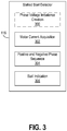
- FIG. 3 An exemplary implementation of the stalled start detector 116 is shown in FIG. 3 according to some embodiments.
- the exemplary stalled start detector 116 has a number of functional modules depicted as discrete blocks, including a motor current acquisition module 302, a positive and negative phase sequence module 304, and a stall indication module 306.
- An optional phase voltage imbalance creation module 300 may also be included in some embodiments to ensure an imbalance in the phase voltages provided to the motor 102.
- any one of the foregoing blocks 300-306 may be divided into several constituent blocks and that two or more of these blocks may be combined into a single block as needed without departing from the scope of the disclosed embodiments.
- the optional phase voltage imbalance creation module 300 is responsible for introducing an imbalance in the phase voltages provided to the motor 102. As mentioned above, such a phase imbalance may be introduced using any suitable method known to those having ordinary skill in the art, including by introducing an impedance in one phase.
- the phase current acquisition module 302 is responsible for acquiring and storing the magnitudes and phase angles of the motor phase currents Ia', Ib', and Ic'. These magnitudes and phase angles may be obtained by the phase current acquisition module 302 from the current sensor 108 discussed earlier with respect to FIG. 1 .
- the positive and negative phase sequence module 304 is responsible for transforming the phase currents Ia', Ib', and Ic' into a positive phase sequence current and a negative phase sequence current.
- a zero phase sequence current also arises, but may be ignored herein due to the lack of a neutral conductor in most induction motors.
- the positive and negative phase sequence module 304 may transform the motor phase currents Ia', Ib', and Ic' by determining the fundamental frequency ⁇ of the phase currents, the magnitudes of the phase currents, and the dominant phase sequence, either a-b-c or a-c-b, from the motor phase currents.
- the module 304 may then perform the symmetrical components transform on the motor phase currents at the fundamental frequency ⁇ using the dominant phase sequence a-b-c or a-c-b as the positive phase sequence to produce a positive phase sequence current I( + ) and a negative phase sequence current I(-) .
- the stall indication module 306 thereafter uses a transient analysis of the positive and negative sequence current magnitudes to determine whether the motor 102 is starting correctly or has stalled. Specifically, the stall indication module 306 calculates a stall indicator by taking a ratio of the positive phase sequence current to the negative phase sequence current, then checking whether the ratio is changing (decreasing) or remains substantially unchanged during the motor startup interval. In some embodiments, in addition to checking for a lack of change in the ratio, the stall indication module 306 may also require the motor phase currents to have a magnitude of at least two times the magnitude of the motor full load current during the startup interval. This requirement confirms that the motor 102 is drawing locked rotor current and is therefore truly stalled.
- FIG. 4 shows an exemplary method for determining the positive and negative sequence components of a 3-phase system using samples of 3-phase current magnitudes.
- the flow chart 400 generally begins at block 402, where samples of the three phase currents (e.g., from an analog-to-digital converter) are passed through digital low pass filters so the remaining signals represent mainly the fundamental 50/60 Hz sine waves of the phase currents.
- the filtered phase currents are used to measure the time between zero crossings of phase a, phase b and phase c. These three time intervals are then averaged and multiplied by two to get the fundamental period of the filtered phase currents.
- the peak magnitude of each filtered phase current is determined over one fundamental period. This may be done, for example, by identifying a positive going zero crossing (i.e., a zero crossing where the current switches from a negative to a positive magnitude) of the filtered phase a, then determining which filtered phase current, b or c, has the next positive going zero crossing. If phase b has the next positive going zero crossing, then the dominant phase sequence is a-b-c (i.e., positive). If phase c has the next positive going zero crossing, then the dominant phase sequence is a-c-b (i.e., negative).
- phase angle (in degrees) of phase b and phase c relative to phase a are calculated, for example, by multiplying the times between zero crossings from block 414 by 360 and then dividing by the times between zero crossings from block 402.
- the phasor representation of each phase is calculated using the phase angles from block 416 and the peak magnitudes from block 406.
- the phase angle may be considered to be zero.
- the positive and negative phase sequence components of the 3-phase system are then calculated at block 420.
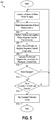
- the flowchart 500 generally begins with an optional step at block 502 where an imbalance may be introduced in the phase voltages being provided to the motor in order to allow the negative phase sequence current to be used.
- measurements of the motor phase currents Ia', Ib', and Ic' are obtained, and at block 506 the motor phase currents are transformed into a positive phase sequence current and a negative phase sequence current using the symmetrical components transform.
- a ratio is obtained of the magnitudes of the positive and negative phase sequence currents, which are calculated using the symmetrical components transformation. The ratio may then be used as a stall indicator by comparing it to a previously obtained ratio at block 510.
Landscapes
- Engineering & Computer Science (AREA)
- Power Engineering (AREA)
- Control Of Ac Motors In General (AREA)
- Motor And Converter Starters (AREA)
Abstract
Description
- The disclosed embodiments relate generally to induction motors and particularly to methods and systems for detecting and protecting such induction motors from a long start condition.
- Induction motors are widely used in industrial applications owing to their low cost and high efficiency and reliability, among other benefits. A typical induction motor includes a stationary member, or stator, having a plurality of windings thereon and a rotating member, or rotor, rotatably disposed within the stator. Applying a sinusoidal or alternating voltage to the stator windings induces a rotating magnetic field that causes the rotor to rotate. Induction motors typically operate on single-phase and three-phase voltages, although two-phase induction motors are also available.
- Various techniques exist for starting an induction motor. One such technique is direct on-line (DOL) starting in which the terminals of the motor are directly connected to a power supply, which is typically connected to the AC main. With DOL starting, a three-phase induction motor may draw between five to eight times its rated full load current immediately after startup, known as "locked rotor" current. As the motor accelerates, the load current drops slightly until the motor reaches about 70% to 80% of its full speed, after which the load current drops more rapidly toward the normal running current of the motor. The time it takes the motor to reach full speed is called the "startup" time and may last several seconds, depending on the size of the motor and the inertia of the driven system.
- Most motor overload protection devices that protect induction motors from current overload take the above startup time into account before disconnecting power to the motors. These devices, which may include circuit breakers, overload relays, and other types of circuit interruption devices, typically delay tripping for some number of seconds based on the "trip class" of the device to accommodate the startup time. A higher trip class may be used for motors that have higher inertia loads, and so on, with some overload protection devices allowing up to 30 seconds for the motor to reach full speed before tripping, known as a "long start."
- Sometimes a motor is stalled or otherwise unable properly to start due to excessive load, motor damage, or other reasons. When this happens, the motor stills draws locked rotor current, but does not rotate or start because the motor has stalled or jammed. Stalled starts, however, are not typically differentiated from long starts in existing overload protection devices. These overload protection devices typically allow a stalled motor to continue drawing locked rotor current until the designated startup period expires before tripping. Such an extended interval of locked rotor current in the motor windings may damage the motor and power supply circuits, generate excessive heat, especially if the motor cooling system is not working, which is often the case when the motor is stalled, and require longer cool down periods before subsequent restarts are allowed.
- To address the above problem, certain high end overload protection devices use analysis of phase shifts that may exist between supply voltage and motor current to detect a stalled start. Other overload protection devices use a tachometer to directly measure motor speed and thereby detect a stalled start. Motor speed may also be estimated, for example, using rotor bar harmonics and the like. However, in addition to increasing complexity and cost, some of these techniques, such as the use of rotor bar harmonics to estimate motor speed and the like, do not function during transient conditions like during a motor start.
- Thus, a need exists for an improved way to detect and protect induction motors from stalled start conditions.
- The embodiments disclosed herein are directed to a motor management system for a multiphase induction motor. The system comprises, among other things, a power supply configured to provide power to the induction motor, and a controller connected to the power supply and configured to control the power provided to the induction motor by the power supply. The system further comprises an overload protection device connected to the power supply and configured to calculate a positive phase sequence current magnitude and a negative phase sequence current magnitude from the power provided to the induction motor during a startup interval of the induction motor. The overload protection device is further configured to remove the power provided to the induction motor based on a ratio of the positive phase sequence current magnitude to the negative phase sequence current magnitude. The overload protection device removes the power provided to the induction motor if the ratio remains substantially unchanged from a ratio of a previously derived positive phase sequence current magnitude to a previously derived negative phase sequence current magnitude during the startup interval
- The foregoing and other advantages of the disclosed embodiments will become apparent upon reading the following detailed description and upon reference to the drawings, wherein:
-
FIG. 1 is a block diagram of an induction motor management system according to some implementations of the disclosed embodiments; -
FIGS. 2A and 2B are circuit models for an induction motor using positive and negative phase sequences, respectively, according to some implementations of the disclosed embodiments; -
FIG. 3 is a block diagram of a stalled start detector according to some implementations of the disclosed embodiments; -
FIG. 4 is a flowchart of a method for calculating positive and negative phase sequences according to some implementations of the disclosed embodiments; and -
FIG. 5 is a flowchart of a method for detecting a stalled start according to some implementations of the disclosed embodiments. - As an initial matter, it will be appreciated that the development of an actual, real commercial application incorporating aspects of the disclosed embodiments will require many implementation specific decisions to achieve the developer's ultimate goal for the commercial embodiment. Such implementation specific decisions may include, and likely are not limited to, compliance with system related, business related, government related and other constraints, which may vary by specific implementation, location and from time to time. While a developer's efforts might be complex and time consuming in an absolute sense, such efforts would nevertheless be a routine undertaking for those of skill in this art having the benefit of this disclosure.
- It should also be understood that the embodiments disclosed and taught herein are susceptible to numerous and various modifications and alternative forms. Thus, the use of a singular term, such as, but not limited to, "a" and the like, is not intended as limiting of the number of items. Similarly, any relational terms, such as, but not limited to, "top," "bottom," "left," "right," "upper," "lower," "down," "up," "side," and the like, used in the written description are for clarity in specific reference to the drawings and are not intended to limit the scope of the invention.
- Referring now to
FIG. 1 , a block diagram of amotor management system 100 for anAC motor 102, such as an induction motor, is shown according to one or more embodiments disclosed herein. Themotor 102 in this example is a typical three-phase induction motor having a stator (not expressly shown), a rotor (not expressly shown) rotatably disposed within the stator, and driven by three phase currents Ia, Ib, and Ic. Although a three-phase motor is shown, it should be understood that a two-phase or other type of multiphase induction motor may also be used without departing from the scope of the disclosed embodiments. As can be seen, themotor management system 100 has several main components, including apower supply module 104, acontroller 106, acurrent sensor 108, and anoverload protection device 110. An AC main 112 provides power for themotor 102 through thepower supply module 104 and anexternal control system 114 provides overall control of themotor 102 through thecontroller 106. - In general operation, the
power supply module 104, which may be for example an Intelligent Power Module (IPM), converts AC power from the AC main 112 into three phase currents Ia, Ib, and Ic for starting and running themotor 102. Thecontroller 106 is typically a microcontroller unit (MCU) programmed to control thepower supply module 104 to produce the appropriate amplitudes and phase angles for the phase currents Ia, Ib, and Ic. These amplitudes and phase angles may be derived by thecontroller 106 using real-time or near real-time measurements of the actual phase currents Ia', Ib', and Ic' in themotor 102 provided by thecurrent sensor 108. Any suitablecurrent sensor 108 may be used, including a Hall effect sensor, current transformer, and the like, that is capable of measuring the phase currents Ia', Ib', and Ic' in themotor 102 in real time or near real time. Theoverload protection device 110, which may be for example a circuit breaker, overload relay, and the like, disconnects or otherwise removes thepower supply module 104 from themotor 102 upon detection of an overload current in themotor 102. - In accordance with the disclosed embodiments, the
overload protection device 110 includes a stalledstart detector 116 configured to detect and differentiate between a permissible long start and a problematic stalled start in themotor 102. This stalledstart detector 116 may be implemented as software, hardware, or a combination of software and hardware in theoverload protection device 110. The stalledstart detector 116 is capable of determining whether themotor 102 is accelerating or decelerating, or whether it is maintaining a nearly constant speed, which means themotor 102 has stalled, through analysis of the motor phase currents. Such information may then be used by theoverload protection device 110 to disconnect or otherwise remove themotor 102 from thepower supply module 104 immediately upon detecting a stalled start condition rather than waiting for overload current conditions to be met. The ability to detect a stalled motor using only phase currents avoids the need to obtain voltage phase shift information, motor speed measurements, or other information that may make the motor more expensive and/or impractical. - Operation of the stalled
start detector 116 may be described with reference toFIGS. 2A and 2B , which showcircuit models phase induction motor 102. These models are based on the recognition that, in practice, most multiphase induction motors have a slight imbalance between their phase voltages and currents. By employing the well-known symmetrical components transform, the phase imbalance may be represented as three balanced sets of phase sequence currents: a positive phase sequence "a-b-c," a negative phase sequence "a-c-b," and a zero phase sequence. Most induction motors are connected without a neutral conductor, so the influence of the zero phase sequence current may be ignored for purposes of the present disclosure. Using the symmetrical components transform and applying the resulting positive and negative phase sequence voltages to their respective circuits produces a more accurate model of the motor. - Referring first to
FIG. 2A , thecircuit model 200a represents the impedance of the positive phase sequence current. In this model, UPS is the positive phase sequence voltage, IPS is the positive phase sequence current, Rs is the stator resistance, Xs is the stator leakage reactance, Xm is the magnetizing reactance, Rfe is the magnetizing resistance, Xr is the rotor leakage reactance, and Rr is the rotor resistance. This rotor resistance may vary according to the speed of themotor 102, as indicated by the variable resistance, Rr (1 - s)/s. The speed of themotor 102 is represented by the slip, s, which has a value of 1 when the motor is stopped and is near zero when the motor is running at full speed. When the slip is 1, the variable resistance is 0 and the rotor resistance for the positive sequence current is simply Rr . When the slip is near 0 (e.g., 0.05), the rotor resistance for the positive sequence current is approximately 20Rr . This variation in rotor resistance is the main reason for the high starting current exhibited by induction motors. -
FIG. 2B shows thecircuit model 200b representing the impedance for the negative phase sequence current. In this model, UNS is the negative phase sequence voltage, INS is the negative phase sequence current, Rs is again the stator resistance, Xs is again the stator leakage reactance, Xm is again the magnetizing reactance, Rfe is again the magnetizing resistance, XrNS is the negative sequence rotor leakage reactance, and RrNS /(2 - s) is the rotor resistance as varied according to the speed of themotor 102. - The primary difference between the two
circuit models motor 102 is stopped, the negative phase sequence has a rotor resistance that is the same as the rotor resistance of the positive phase sequence, Rr . But when the slip is near 0 (e.g., 0.05), meaning themotor 102 is running at full speed, the negative phase sequence has a rotor resistance of only slightly more than 0.5Rr , whereas the rotor resistance for the positive phase sequence is approximately 20Rr . This difference helps explain why an imbalance in the motor phase voltages, which is what gives rise to the negative phase sequence voltage, is often a problem for induction motors. The motor presents essentially the same low impedance to negative phase sequence voltage at all speeds that it presents to the positive phase sequence voltage when stalled. Thus, assuming that the locked rotor current is between 6 and 8 times the full load running current, a negative phase sequence voltage magnitude of only 5% would result in between 30% and 40% more current in the motor when running. - The salient point above is that the voltage imbalance may be represented using a negative phase sequence, which in turn allows a stalled motor condition to be detected according to the embodiments disclosed herein. It is therefore important that some amount of imbalance exists in the phase voltages being fed to the
motor 102. Most practical motor implementations have typically less than 0.5% phase imbalance (2 volts at 460VAC). This phase imbalance, while small, is sufficient to create a negative phase sequence current, with the exact magnitude of the negative phase sequence current being dependent on a number of motor characteristics, including the amount of unbalance. In a typical motor, for example, the magnitude of the negative phase sequence current falls between 2% and 5% of the motor full load running current. As an alternative, a phase imbalance may be intentionally introduced in some embodiments, for example, by adding impedance to one phase or using other techniques known to those having ordinary skill in the art. - In accordance with the disclosed embodiments, the stalled
start detector 116 detects a stalled motor condition by using the discovery that with an unbalanced three-phase voltage feeding an induction motor, the ratio between the positive and negative phase sequence current magnitudes changes based on the speed of the motor. Specifically, as motor speed increases from zero, the negative phase sequence current magnitude increases, the positive phase sequence current magnitude becomes smaller, and the ratio decreases. This allows the stalledstart detector 116 to determine whether themotor 102 is accelerating and therefore starting properly or whether it has stalled, basically by monitoring the change in the ratio of the current magnitudes. These current magnitudes may be calculated by applying the well-known symmetrical components transform to the three phase currents (see, e.g., "Method of Symmetrical Co-Ordinates Applied to the Solution of Polyphase Networks," AIEE Transactions, Vol. 37, Part II, pp. 1027-1140 (1918)). - Once the positive and negative phase sequence current magnitudes are known, the stalled
start detector 116 may use these current magnitudes to derive a stall indicator, SI, by calculating the ratio of the positive phase sequence current magnitude to the negative phase sequence current magnitude, for example, SI = 10/1. The stalledstart detector 116 may then monitor this stall indicator during the motor startup interval to determine whether themotor 102 is starting properly or whether it has stalled. If the stall indicator is changing (decreasing) during the motor startup interval, then themotor 102 is accelerating and therefore starting properly. The change is largely unaffected by variations in stator resistance and is also independent of the specific values of the current magnitudes. It is also independent of the percent of voltage imbalance as well as other factors and parameters, including motor specific parameters, assuming these factors and parameters stay constant during the motor startup interval. Thus, by checking for a change in the stall indicator during motor startup, the stalledstart detector 116 may determine whether themotor 102 is starting properly or has stalled. - An exemplary implementation of the stalled
start detector 116 is shown inFIG. 3 according to some embodiments. As can be seen inFIG. 3 , the exemplary stalledstart detector 116 has a number of functional modules depicted as discrete blocks, including a motorcurrent acquisition module 302, a positive and negativephase sequence module 304, and astall indication module 306. An optional phase voltageimbalance creation module 300 may also be included in some embodiments to ensure an imbalance in the phase voltages provided to themotor 102. Those having ordinary skill in the art will of course understand that any one of the foregoing blocks 300-306 may be divided into several constituent blocks and that two or more of these blocks may be combined into a single block as needed without departing from the scope of the disclosed embodiments. - In general operation, the optional phase voltage
imbalance creation module 300 is responsible for introducing an imbalance in the phase voltages provided to themotor 102. As mentioned above, such a phase imbalance may be introduced using any suitable method known to those having ordinary skill in the art, including by introducing an impedance in one phase. The phasecurrent acquisition module 302 is responsible for acquiring and storing the magnitudes and phase angles of the motor phase currents Ia', Ib', and Ic'. These magnitudes and phase angles may be obtained by the phasecurrent acquisition module 302 from thecurrent sensor 108 discussed earlier with respect toFIG. 1 . - The positive and negative
phase sequence module 304, as the name suggests, is responsible for transforming the phase currents Ia', Ib', and Ic' into a positive phase sequence current and a negative phase sequence current. A zero phase sequence current also arises, but may be ignored herein due to the lack of a neutral conductor in most induction motors. In some embodiments, the positive and negativephase sequence module 304 may transform the motor phase currents Ia', Ib', and Ic' by determining the fundamental frequency ω of the phase currents, the magnitudes of the phase currents, and the dominant phase sequence, either a-b-c or a-c-b, from the motor phase currents. Themodule 304 may then perform the symmetrical components transform on the motor phase currents at the fundamental frequency ω using the dominant phase sequence a-b-c or a-c-b as the positive phase sequence to produce a positive phase sequence current I(+) and a negative phase sequence current I(-). - The
stall indication module 306 thereafter uses a transient analysis of the positive and negative sequence current magnitudes to determine whether themotor 102 is starting correctly or has stalled. Specifically, thestall indication module 306 calculates a stall indicator by taking a ratio of the positive phase sequence current to the negative phase sequence current, then checking whether the ratio is changing (decreasing) or remains substantially unchanged during the motor startup interval. In some embodiments, in addition to checking for a lack of change in the ratio, thestall indication module 306 may also require the motor phase currents to have a magnitude of at least two times the magnitude of the motor full load current during the startup interval. This requirement confirms that themotor 102 is drawing locked rotor current and is therefore truly stalled. - Additional details of the operation of the positive and negative
phase sequence module 304 are provided inFIG. 4 via aflow chart 400 according to some embodiments. Thisflow chart 400 shows an exemplary method for determining the positive and negative sequence components of a 3-phase system using samples of 3-phase current magnitudes. Theflow chart 400 generally begins atblock 402, where samples of the three phase currents (e.g., from an analog-to-digital converter) are passed through digital low pass filters so the remaining signals represent mainly the fundamental 50/60 Hz sine waves of the phase currents. Atblock 404, the filtered phase currents are used to measure the time between zero crossings of phase a, phase b and phase c. These three time intervals are then averaged and multiplied by two to get the fundamental period of the filtered phase currents. - Next, at
block 406, the peak magnitude of each filtered phase current is determined over one fundamental period. This may be done, for example, by identifying a positive going zero crossing (i.e., a zero crossing where the current switches from a negative to a positive magnitude) of the filtered phase a, then determining which filtered phase current, b or c, has the next positive going zero crossing. If phase b has the next positive going zero crossing, then the dominant phase sequence is a-b-c (i.e., positive). If phase c has the next positive going zero crossing, then the dominant phase sequence is a-c-b (i.e., negative). - Thereafter, at
block 410, a determination is made whether the dominant phase sequence is a-c-b. If the determination is yes, then the data for phase b and phase c are swamped in the remaining steps. Otherwise, atblock 414, starting from a positive going zero crossing of phase a, the time until the next positive going zero crossing of phase b and phase c are measured. Atblock 416, the phase angle (in degrees) of phase b and phase c relative to phase a are calculated, for example, by multiplying the times between zero crossings fromblock 414 by 360 and then dividing by the times between zero crossings fromblock 402. - Once the above is done, at
block 418, the phasor representation of each phase is calculated using the phase angles fromblock 416 and the peak magnitudes fromblock 406. For phase a, the phase angle may be considered to be zero. The positive and negative phase sequence components of the 3-phase system are then calculated atblock 420. In some embodiments, the positive sequence component of the 3-phase system may be calculated by performing the following vector calculation: I(+) = 1/3 ∗ (I(a) + I(b) ∗ 1∠120 + I(c) ∗ 1∠240). In some embodiments, the negative sequence component of the 3-phase phase system may be calculated by performing the following vector calculation: I(-) = 1/3 ∗ (I(a) + I(b) ∗ 1∠240 + I(c) ∗ 1∠120). - Thus far, a number of specific implementations have been described for the disclosed embodiments. Following now in
FIG. 5 are general guidelines in the form of aflow chart 500 that may be used to implement one or more of the disclosed embodiments. Theflowchart 500 generally begins with an optional step atblock 502 where an imbalance may be introduced in the phase voltages being provided to the motor in order to allow the negative phase sequence current to be used. Atblock 504, measurements of the motor phase currents Ia', Ib', and Ic' are obtained, and atblock 506 the motor phase currents are transformed into a positive phase sequence current and a negative phase sequence current using the symmetrical components transform. Atblock 508, a ratio is obtained of the magnitudes of the positive and negative phase sequence currents, which are calculated using the symmetrical components transformation. The ratio may then be used as a stall indicator by comparing it to a previously obtained ratio atblock 510. - A determination is made at
block 512 whether the ratio has changed (decreased) from the previously obtained ratio. If the determination is yes, then the motor is considered to be starting properly, and theflowchart 500 returns to the beginning atblock 502. If the determination is no, then a determination is made atblock 514 whether the motor phase currents are at least twice the motor full load current. If the determination is no, then the motor is not drawing locked rotor current and is therefore not considered to be truly stalled, and theflowchart 500 again returns to the beginning atblock 502. If the determination is yes, then the motor is considered to be truly stalled, and the overload protection device is tripped to remove or otherwise disconnect the motor from the power supply. - While particular aspects, implementations, and applications of the present disclosure have been illustrated and described, it is to be understood that the present disclosure is not limited to the precise construction and compositions disclosed herein and that various modifications, changes, and variations may be apparent from the foregoing descriptions without departing from the scope of the disclosed embodiments as defined in the appended claims.
Claims (5)
- A motor management system for a multiphase induction motor, comprising:a power supply configured to provide power to the induction motor;a controller connected to the power supply and configured to control the power provided to the induction motor by the power supply; andan overload protection device connected to the power supply and configured to calculate a positive phase sequence current magnitude and a negative phase sequence current magnitude from the power provided to the induction motor during a startup interval of the induction motor;wherein the overload protection device is further configured to remove the power provided to the induction motor based on a ratio of the positive phase sequence current magnitude to the negative phase sequence current magnitude; and
wherein the overload protection device removes the power provided to the induction motor if the ratio remains substantially unchanged from a ratio of a previously derived positive phase sequence current magnitude to a previously derived negative phase sequence current magnitude during the startup interval. - The motor management system of claim 1, wherein the overload protection device is further configured to introduce an imbalance between one or more phase voltages in the power provided to the induction motor.
- The motor management system of claim 1, wherein the overload protection device is further configured to remove the power provided to the induction motor only if: (i) the ratio remains substantially unchanged from a ratio of a previously calculated positive phase sequence current magnitude to a previously calculated negative phase sequence current magnitude, and (ii) a current drawn by the induction motor during the startup interval exceeds a full load current of the induction motor by a predefined amount.
- The motor management system of claim 3, wherein the predefined amount is at least two times the full load current of the induction motor.
- The motor management system of claim 3, wherein the predefined amount is sufficient to ensure that the induction motor is drawing locked rotor current during the startup interval.
Applications Claiming Priority (2)
| Application Number | Priority Date | Filing Date | Title |
|---|---|---|---|
| US14/822,675 US10128779B2 (en) | 2015-08-10 | 2015-08-10 | Induction motor long start protection |
| EP16181873.7A EP3131197B1 (en) | 2015-08-10 | 2016-07-29 | Induction motor long start protection |
Related Parent Applications (2)
| Application Number | Title | Priority Date | Filing Date |
|---|---|---|---|
| EP16181873.7A Division EP3131197B1 (en) | 2015-08-10 | 2016-07-29 | Induction motor long start protection |
| EP16181873.7A Division-Into EP3131197B1 (en) | 2015-08-10 | 2016-07-29 | Induction motor long start protection |
Publications (2)
| Publication Number | Publication Date |
|---|---|
| EP3611836A1 true EP3611836A1 (en) | 2020-02-19 |
| EP3611836B1 EP3611836B1 (en) | 2021-07-21 |
Family
ID=56555307
Family Applications (2)
| Application Number | Title | Priority Date | Filing Date |
|---|---|---|---|
| EP19200791.2A Active EP3611836B1 (en) | 2015-08-10 | 2016-07-29 | Induction motor long start protection |
| EP16181873.7A Active EP3131197B1 (en) | 2015-08-10 | 2016-07-29 | Induction motor long start protection |
Family Applications After (1)
| Application Number | Title | Priority Date | Filing Date |
|---|---|---|---|
| EP16181873.7A Active EP3131197B1 (en) | 2015-08-10 | 2016-07-29 | Induction motor long start protection |
Country Status (3)
| Country | Link |
|---|---|
| US (1) | US10128779B2 (en) |
| EP (2) | EP3611836B1 (en) |
| CN (1) | CN106452195B (en) |
Families Citing this family (7)
| Publication number | Priority date | Publication date | Assignee | Title |
|---|---|---|---|---|
| US10903776B2 (en) * | 2017-05-31 | 2021-01-26 | Abb Schweiz Ag | Industrial electrical machine |
| US10461537B2 (en) | 2017-12-19 | 2019-10-29 | Eurotherm Limited | Method to drive a power control device connected to unbalanced three-phase loads when no neutral reference is available in an alternative electrical network |
| US10424913B2 (en) * | 2017-12-20 | 2019-09-24 | Schneider Electric USA, Inc. | Dynamic motor current phase unbalance protection |
| NO346979B1 (en) * | 2018-12-08 | 2023-03-27 | Mohammad Amin Namjoo | Dahlander electromotor startup module |
| CN109742735A (en) * | 2018-12-28 | 2019-05-10 | 无锡新大力电机有限公司 | A kind of New-type electric machine stall protector |
| US11451171B2 (en) | 2019-06-19 | 2022-09-20 | Schneider Electric USA, Inc. | Motor branch circuit health monitoring method |
| US20250183652A1 (en) * | 2022-01-03 | 2025-06-05 | Copeland Comfort Control Lp | Adaptive undervoltage protection for three-phase load using single current sensor |
Citations (3)
| Publication number | Priority date | Publication date | Assignee | Title |
|---|---|---|---|---|
| US5436784A (en) * | 1993-08-11 | 1995-07-25 | Schweitzer Engineering Laboratories, Inc. | Motor protection relay using thermal models |
| US20050067992A1 (en) * | 2003-09-30 | 2005-03-31 | Yehia El-Ibiary | System and method for establishing motor efficiency during balanced or unbalanced operating conditions |
| US20130088799A1 (en) * | 2011-10-07 | 2013-04-11 | Schweitzer Engineering Laboratories, Inc. | Asset Condition Monitoring in an Electric Motor |
Family Cites Families (16)
| Publication number | Priority date | Publication date | Assignee | Title |
|---|---|---|---|---|
| US3818270A (en) | 1972-12-11 | 1974-06-18 | G Hagiz | Overload interrupt systems for three-phase induction motor |
| US4288737A (en) * | 1979-05-21 | 1981-09-08 | Esco Manufacturing Company | Regulator-compensator control |
| GB2128425B (en) | 1982-10-08 | 1986-06-25 | Newelec Pretoria | Stall detection apparatus |
| US4600961A (en) * | 1983-09-01 | 1986-07-15 | Westinghouse Electric Corp. | Protective relay apparatus for detecting high-impedance ground faults |
| US4636702A (en) | 1984-08-09 | 1987-01-13 | Louis W. Parker | Energy economizer controlled-current start and protection for induction motors |
| US5786708A (en) * | 1996-04-01 | 1998-07-28 | General Electric Company | Self-tuning and compensating turn fault detector |
| US5883489A (en) * | 1996-09-27 | 1999-03-16 | General Electric Company | High speed deep well pump for residential use |
| US6798191B1 (en) * | 1999-08-09 | 2004-09-28 | Power Measurement Ltd. | Revenue meter with a graphic user interface being operative to display scalable objects |
| US6611771B1 (en) * | 2000-10-04 | 2003-08-26 | Eaton Corporation | Method and apparatus to detect a stator turn fault in an AC motor |
| US20030088799A1 (en) | 2001-11-05 | 2003-05-08 | Bodas Devadatta V. | Method and apparatus for regulation of electrical component temperature and power consumption rate through bus width reconfiguration |
| CN201315473Y (en) * | 2008-12-09 | 2009-09-23 | 李俊苇 | Asynchronous motor protector |
| US8330407B2 (en) * | 2009-12-22 | 2012-12-11 | Bitzer Compressores Ltda | Electronic system and protection method for electric motors |
| CN101976994A (en) * | 2010-09-17 | 2011-02-16 | 三一重工股份有限公司 | Conversion circuit, method and system for detecting phase sequence of three-phase power supply, and motor |
| FR2968856B1 (en) | 2010-12-08 | 2014-10-10 | Areva T & D Prot & Controle | MOTOR PROTECTION RELAY FOR OPTIMIZING THE MONITORING AND PROTECTION OF AN ELECTRIC MOTOR |
| US9255969B2 (en) * | 2012-05-21 | 2016-02-09 | General Electric Company | Prognostics and life estimation of electrical machines |
| CN104020351B (en) * | 2014-06-24 | 2016-08-17 | 哈尔滨同为电气股份有限公司 | A kind of be applicable to APF fractional harmonic wave detection method under laod unbalance system |
-
2015
- 2015-08-10 US US14/822,675 patent/US10128779B2/en active Active
-
2016
- 2016-07-27 CN CN201610596654.4A patent/CN106452195B/en active Active
- 2016-07-29 EP EP19200791.2A patent/EP3611836B1/en active Active
- 2016-07-29 EP EP16181873.7A patent/EP3131197B1/en active Active
Patent Citations (3)
| Publication number | Priority date | Publication date | Assignee | Title |
|---|---|---|---|---|
| US5436784A (en) * | 1993-08-11 | 1995-07-25 | Schweitzer Engineering Laboratories, Inc. | Motor protection relay using thermal models |
| US20050067992A1 (en) * | 2003-09-30 | 2005-03-31 | Yehia El-Ibiary | System and method for establishing motor efficiency during balanced or unbalanced operating conditions |
| US20130088799A1 (en) * | 2011-10-07 | 2013-04-11 | Schweitzer Engineering Laboratories, Inc. | Asset Condition Monitoring in an Electric Motor |
Non-Patent Citations (2)
| Title |
|---|
| "Method of Symmetrical Co-Ordinates Applied to the Solution of Polyphase Networks", AIEE TRANSACTIONS, vol. 37, 1918, pages 1027 - 1140 |
| DECASTRO J ET AL: "Stall protection of large induction motors", PETROLEUM AND CHEMICAL INDUSTRY CONFERENCE, 1994. RECORD OF CONFERENCE PAPERS., INSTITUTE OF ELECTRICAL AND ELECTRONICS ENGINEERS INCORPORAT ED INDUSTRY APPLICATIONS SOCIETY 41ST ANNUAL VANCOUVER, BC, CANADA 12-14 SEPT. 1994, NEW YORK, NY, USA,IEEE, 12 September 1994 (1994-09-12), pages 133 - 139, XP010123983, ISBN: 978-0-7803-1987-5, DOI: 10.1109/PCICON.1994.347622 * |
Also Published As
| Publication number | Publication date |
|---|---|
| US20170047869A1 (en) | 2017-02-16 |
| CN106452195B (en) | 2021-11-05 |
| US10128779B2 (en) | 2018-11-13 |
| CN106452195A (en) | 2017-02-22 |
| EP3131197A3 (en) | 2017-03-01 |
| EP3611836B1 (en) | 2021-07-21 |
| EP3131197A2 (en) | 2017-02-15 |
| EP3131197B1 (en) | 2019-12-04 |
Similar Documents
| Publication | Publication Date | Title |
|---|---|---|
| EP3611836B1 (en) | Induction motor long start protection | |
| CA2689512C (en) | System and method to determine electric motor efficiency nonintrusively | |
| US9933487B2 (en) | System and method for detecting, localizing, and quantifying stator winding faults in AC motors | |
| EP2394183B1 (en) | Robust on-line stator turn fault identification system | |
| EP2905630B1 (en) | Fault detection in brushless exciters | |
| US8587244B2 (en) | Method and system for determining deterioration of permanent magnets of electric apparatus | |
| Yang et al. | Online open-phase fault detection for permanent magnet machines with low fault harmonic magnitudes | |
| CN110546881B (en) | Segmented estimation of negative sequence voltage for fault detection in electrical systems | |
| CN108141169A (en) | For identifying the method for the discrete instantaneous angular velocity of Mechatronic Systems | |
| CN105486969B (en) | Compressor reverse connection fault detection method, protection method and device | |
| JP2003079200A (en) | Motor drive system | |
| EP3614559B1 (en) | Induction motor speed estimation method and power conversion device using same | |
| CN105580267A (en) | Power conversion device and power conversion method | |
| KR102900166B1 (en) | Motor monitoring device and motor monitoring method | |
| Khov et al. | Detection of turn short-circuit faults in stator of PMSM by on-line parameter estimation | |
| Jannati et al. | Modeling of balanced and unbalanced three-phase induction motor under balanced and unbalanced supply based on winding function method | |
| EP3133732B1 (en) | Power conversion device and power conversion method | |
| EP3703249B1 (en) | Power conversion device and controlling method therefor | |
| He et al. | Diagnosis of stator short-circuit faults in an IPM synchronous machine using a space-vector pendulous oscillation method | |
| JP6108109B2 (en) | Control device for permanent magnet type synchronous motor | |
| Finney et al. | Electromagnetic torque from event report data—A measure of machine performance | |
| JP2010252503A (en) | Position and speed sensorless controller of pm motor | |
| Tsypkin | Induction Motor Condition Monitoring: Slip Frequency and Pole Pass Frequency–a Clarification of Definitions | |
| CN102636749A (en) | Method for measuring motor parameters | |
| JP2619168B2 (en) | Instantaneous torque measurement device for three-phase induction motor |
Legal Events
| Date | Code | Title | Description |
|---|---|---|---|
| PUAI | Public reference made under article 153(3) epc to a published international application that has entered the european phase |
Free format text: ORIGINAL CODE: 0009012 |
|
| STAA | Information on the status of an ep patent application or granted ep patent |
Free format text: STATUS: THE APPLICATION HAS BEEN PUBLISHED |
|
| AC | Divisional application: reference to earlier application |
Ref document number: 3131197 Country of ref document: EP Kind code of ref document: P |
|
| AK | Designated contracting states |
Kind code of ref document: A1 Designated state(s): AL AT BE BG CH CY CZ DE DK EE ES FI FR GB GR HR HU IE IS IT LI LT LU LV MC MK MT NL NO PL PT RO RS SE SI SK SM TR |
|
| STAA | Information on the status of an ep patent application or granted ep patent |
Free format text: STATUS: REQUEST FOR EXAMINATION WAS MADE |
|
| 17P | Request for examination filed |
Effective date: 20200326 |
|
| RBV | Designated contracting states (corrected) |
Designated state(s): AL AT BE BG CH CY CZ DE DK EE ES FI FR GB GR HR HU IE IS IT LI LT LU LV MC MK MT NL NO PL PT RO RS SE SI SK SM TR |
|
| STAA | Information on the status of an ep patent application or granted ep patent |
Free format text: STATUS: EXAMINATION IS IN PROGRESS |
|
| 17Q | First examination report despatched |
Effective date: 20200602 |
|
| GRAP | Despatch of communication of intention to grant a patent |
Free format text: ORIGINAL CODE: EPIDOSNIGR1 |
|
| STAA | Information on the status of an ep patent application or granted ep patent |
Free format text: STATUS: GRANT OF PATENT IS INTENDED |
|
| INTG | Intention to grant announced |
Effective date: 20210315 |
|
| GRAS | Grant fee paid |
Free format text: ORIGINAL CODE: EPIDOSNIGR3 |
|
| GRAA | (expected) grant |
Free format text: ORIGINAL CODE: 0009210 |
|
| STAA | Information on the status of an ep patent application or granted ep patent |
Free format text: STATUS: THE PATENT HAS BEEN GRANTED |
|
| AC | Divisional application: reference to earlier application |
Ref document number: 3131197 Country of ref document: EP Kind code of ref document: P |
|
| AK | Designated contracting states |
Kind code of ref document: B1 Designated state(s): AL AT BE BG CH CY CZ DE DK EE ES FI FR GB GR HR HU IE IS IT LI LT LU LV MC MK MT NL NO PL PT RO RS SE SI SK SM TR |
|
| REG | Reference to a national code |
Ref country code: GB Ref legal event code: FG4D |
|
| REG | Reference to a national code |
Ref country code: CH Ref legal event code: EP |
|
| REG | Reference to a national code |
Ref country code: DE Ref legal event code: R096 Ref document number: 602016061163 Country of ref document: DE |
|
| REG | Reference to a national code |
Ref country code: AT Ref legal event code: REF Ref document number: 1413540 Country of ref document: AT Kind code of ref document: T Effective date: 20210815 |
|
| REG | Reference to a national code |
Ref country code: IE Ref legal event code: FG4D |
|
| REG | Reference to a national code |
Ref country code: LT Ref legal event code: MG9D |
|
| REG | Reference to a national code |
Ref country code: NL Ref legal event code: MP Effective date: 20210721 |
|
| REG | Reference to a national code |
Ref country code: AT Ref legal event code: MK05 Ref document number: 1413540 Country of ref document: AT Kind code of ref document: T Effective date: 20210721 |
|
| PG25 | Lapsed in a contracting state [announced via postgrant information from national office to epo] |
Ref country code: SE Free format text: LAPSE BECAUSE OF FAILURE TO SUBMIT A TRANSLATION OF THE DESCRIPTION OR TO PAY THE FEE WITHIN THE PRESCRIBED TIME-LIMIT Effective date: 20210721 Ref country code: RS Free format text: LAPSE BECAUSE OF FAILURE TO SUBMIT A TRANSLATION OF THE DESCRIPTION OR TO PAY THE FEE WITHIN THE PRESCRIBED TIME-LIMIT Effective date: 20210721 Ref country code: FI Free format text: LAPSE BECAUSE OF FAILURE TO SUBMIT A TRANSLATION OF THE DESCRIPTION OR TO PAY THE FEE WITHIN THE PRESCRIBED TIME-LIMIT Effective date: 20210721 Ref country code: ES Free format text: LAPSE BECAUSE OF FAILURE TO SUBMIT A TRANSLATION OF THE DESCRIPTION OR TO PAY THE FEE WITHIN THE PRESCRIBED TIME-LIMIT Effective date: 20210721 Ref country code: HR Free format text: LAPSE BECAUSE OF FAILURE TO SUBMIT A TRANSLATION OF THE DESCRIPTION OR TO PAY THE FEE WITHIN THE PRESCRIBED TIME-LIMIT Effective date: 20210721 Ref country code: PT Free format text: LAPSE BECAUSE OF FAILURE TO SUBMIT A TRANSLATION OF THE DESCRIPTION OR TO PAY THE FEE WITHIN THE PRESCRIBED TIME-LIMIT Effective date: 20211122 Ref country code: NO Free format text: LAPSE BECAUSE OF FAILURE TO SUBMIT A TRANSLATION OF THE DESCRIPTION OR TO PAY THE FEE WITHIN THE PRESCRIBED TIME-LIMIT Effective date: 20211021 Ref country code: NL Free format text: LAPSE BECAUSE OF FAILURE TO SUBMIT A TRANSLATION OF THE DESCRIPTION OR TO PAY THE FEE WITHIN THE PRESCRIBED TIME-LIMIT Effective date: 20210721 Ref country code: LT Free format text: LAPSE BECAUSE OF FAILURE TO SUBMIT A TRANSLATION OF THE DESCRIPTION OR TO PAY THE FEE WITHIN THE PRESCRIBED TIME-LIMIT Effective date: 20210721 Ref country code: AT Free format text: LAPSE BECAUSE OF FAILURE TO SUBMIT A TRANSLATION OF THE DESCRIPTION OR TO PAY THE FEE WITHIN THE PRESCRIBED TIME-LIMIT Effective date: 20210721 Ref country code: BG Free format text: LAPSE BECAUSE OF FAILURE TO SUBMIT A TRANSLATION OF THE DESCRIPTION OR TO PAY THE FEE WITHIN THE PRESCRIBED TIME-LIMIT Effective date: 20211021 |
|
| PG25 | Lapsed in a contracting state [announced via postgrant information from national office to epo] |
Ref country code: PL Free format text: LAPSE BECAUSE OF FAILURE TO SUBMIT A TRANSLATION OF THE DESCRIPTION OR TO PAY THE FEE WITHIN THE PRESCRIBED TIME-LIMIT Effective date: 20210721 Ref country code: LV Free format text: LAPSE BECAUSE OF FAILURE TO SUBMIT A TRANSLATION OF THE DESCRIPTION OR TO PAY THE FEE WITHIN THE PRESCRIBED TIME-LIMIT Effective date: 20210721 Ref country code: GR Free format text: LAPSE BECAUSE OF FAILURE TO SUBMIT A TRANSLATION OF THE DESCRIPTION OR TO PAY THE FEE WITHIN THE PRESCRIBED TIME-LIMIT Effective date: 20211022 |
|
| REG | Reference to a national code |
Ref country code: CH Ref legal event code: PL |
|
| REG | Reference to a national code |
Ref country code: BE Ref legal event code: MM Effective date: 20210731 |
|
| REG | Reference to a national code |
Ref country code: DE Ref legal event code: R097 Ref document number: 602016061163 Country of ref document: DE |
|
| PG25 | Lapsed in a contracting state [announced via postgrant information from national office to epo] |
Ref country code: LI Free format text: LAPSE BECAUSE OF NON-PAYMENT OF DUE FEES Effective date: 20210731 Ref country code: DK Free format text: LAPSE BECAUSE OF FAILURE TO SUBMIT A TRANSLATION OF THE DESCRIPTION OR TO PAY THE FEE WITHIN THE PRESCRIBED TIME-LIMIT Effective date: 20210721 Ref country code: CH Free format text: LAPSE BECAUSE OF NON-PAYMENT OF DUE FEES Effective date: 20210731 |
|
| PLBE | No opposition filed within time limit |
Free format text: ORIGINAL CODE: 0009261 |
|
| STAA | Information on the status of an ep patent application or granted ep patent |
Free format text: STATUS: NO OPPOSITION FILED WITHIN TIME LIMIT |
|
| PG25 | Lapsed in a contracting state [announced via postgrant information from national office to epo] |
Ref country code: SM Free format text: LAPSE BECAUSE OF FAILURE TO SUBMIT A TRANSLATION OF THE DESCRIPTION OR TO PAY THE FEE WITHIN THE PRESCRIBED TIME-LIMIT Effective date: 20210721 Ref country code: SK Free format text: LAPSE BECAUSE OF FAILURE TO SUBMIT A TRANSLATION OF THE DESCRIPTION OR TO PAY THE FEE WITHIN THE PRESCRIBED TIME-LIMIT Effective date: 20210721 Ref country code: RO Free format text: LAPSE BECAUSE OF FAILURE TO SUBMIT A TRANSLATION OF THE DESCRIPTION OR TO PAY THE FEE WITHIN THE PRESCRIBED TIME-LIMIT Effective date: 20210721 Ref country code: MC Free format text: LAPSE BECAUSE OF FAILURE TO SUBMIT A TRANSLATION OF THE DESCRIPTION OR TO PAY THE FEE WITHIN THE PRESCRIBED TIME-LIMIT Effective date: 20210721 Ref country code: EE Free format text: LAPSE BECAUSE OF FAILURE TO SUBMIT A TRANSLATION OF THE DESCRIPTION OR TO PAY THE FEE WITHIN THE PRESCRIBED TIME-LIMIT Effective date: 20210721 Ref country code: CZ Free format text: LAPSE BECAUSE OF FAILURE TO SUBMIT A TRANSLATION OF THE DESCRIPTION OR TO PAY THE FEE WITHIN THE PRESCRIBED TIME-LIMIT Effective date: 20210721 Ref country code: AL Free format text: LAPSE BECAUSE OF FAILURE TO SUBMIT A TRANSLATION OF THE DESCRIPTION OR TO PAY THE FEE WITHIN THE PRESCRIBED TIME-LIMIT Effective date: 20210721 Ref country code: LU Free format text: LAPSE BECAUSE OF NON-PAYMENT OF DUE FEES Effective date: 20210729 |
|
| 26N | No opposition filed |
Effective date: 20220422 |
|
| PG25 | Lapsed in a contracting state [announced via postgrant information from national office to epo] |
Ref country code: IT Free format text: LAPSE BECAUSE OF FAILURE TO SUBMIT A TRANSLATION OF THE DESCRIPTION OR TO PAY THE FEE WITHIN THE PRESCRIBED TIME-LIMIT Effective date: 20210721 Ref country code: IE Free format text: LAPSE BECAUSE OF NON-PAYMENT OF DUE FEES Effective date: 20210729 Ref country code: BE Free format text: LAPSE BECAUSE OF NON-PAYMENT OF DUE FEES Effective date: 20210731 |
|
| PG25 | Lapsed in a contracting state [announced via postgrant information from national office to epo] |
Ref country code: CY Free format text: LAPSE BECAUSE OF FAILURE TO SUBMIT A TRANSLATION OF THE DESCRIPTION OR TO PAY THE FEE WITHIN THE PRESCRIBED TIME-LIMIT Effective date: 20210721 |
|
| PG25 | Lapsed in a contracting state [announced via postgrant information from national office to epo] |
Ref country code: HU Free format text: LAPSE BECAUSE OF FAILURE TO SUBMIT A TRANSLATION OF THE DESCRIPTION OR TO PAY THE FEE WITHIN THE PRESCRIBED TIME-LIMIT; INVALID AB INITIO Effective date: 20160729 |
|
| PG25 | Lapsed in a contracting state [announced via postgrant information from national office to epo] |
Ref country code: MK Free format text: LAPSE BECAUSE OF FAILURE TO SUBMIT A TRANSLATION OF THE DESCRIPTION OR TO PAY THE FEE WITHIN THE PRESCRIBED TIME-LIMIT Effective date: 20210721 |
|
| PG25 | Lapsed in a contracting state [announced via postgrant information from national office to epo] |
Ref country code: MT Free format text: LAPSE BECAUSE OF FAILURE TO SUBMIT A TRANSLATION OF THE DESCRIPTION OR TO PAY THE FEE WITHIN THE PRESCRIBED TIME-LIMIT Effective date: 20210721 |
|
| PGFP | Annual fee paid to national office [announced via postgrant information from national office to epo] |
Ref country code: DE Payment date: 20250728 Year of fee payment: 10 |
|
| PGFP | Annual fee paid to national office [announced via postgrant information from national office to epo] |
Ref country code: GB Payment date: 20250722 Year of fee payment: 10 |
|
| PGFP | Annual fee paid to national office [announced via postgrant information from national office to epo] |
Ref country code: FR Payment date: 20250725 Year of fee payment: 10 |
|
| PG25 | Lapsed in a contracting state [announced via postgrant information from national office to epo] |
Ref country code: TR Free format text: LAPSE BECAUSE OF FAILURE TO SUBMIT A TRANSLATION OF THE DESCRIPTION OR TO PAY THE FEE WITHIN THE PRESCRIBED TIME-LIMIT Effective date: 20210721 |