EP3611299A1 - Water drainage valve for dual-drum clothes washing machine, and dual-drum clothes washing machine using said water drainage valve - Google Patents
Water drainage valve for dual-drum clothes washing machine, and dual-drum clothes washing machine using said water drainage valve Download PDFInfo
- Publication number
- EP3611299A1 EP3611299A1 EP18784874.2A EP18784874A EP3611299A1 EP 3611299 A1 EP3611299 A1 EP 3611299A1 EP 18784874 A EP18784874 A EP 18784874A EP 3611299 A1 EP3611299 A1 EP 3611299A1
- Authority
- EP
- European Patent Office
- Prior art keywords
- water drainage
- drainage valve
- water
- arc
- pull rod
- Prior art date
- Legal status (The legal status is an assumption and is not a legal conclusion. Google has not performed a legal analysis and makes no representation as to the accuracy of the status listed.)
- Granted
Links
Images


Classifications
-
- D—TEXTILES; PAPER
- D06—TREATMENT OF TEXTILES OR THE LIKE; LAUNDERING; FLEXIBLE MATERIALS NOT OTHERWISE PROVIDED FOR
- D06F—LAUNDERING, DRYING, IRONING, PRESSING OR FOLDING TEXTILE ARTICLES
- D06F31/00—Washing installations comprising an assembly of several washing machines or washing units, e.g. continuous flow assemblies
-
- D—TEXTILES; PAPER
- D06—TREATMENT OF TEXTILES OR THE LIKE; LAUNDERING; FLEXIBLE MATERIALS NOT OTHERWISE PROVIDED FOR
- D06F—LAUNDERING, DRYING, IRONING, PRESSING OR FOLDING TEXTILE ARTICLES
- D06F39/00—Details of washing machines not specific to a single type of machines covered by groups D06F9/00 - D06F27/00
- D06F39/08—Liquid supply or discharge arrangements
- D06F39/083—Liquid discharge or recirculation arrangements
-
- F—MECHANICAL ENGINEERING; LIGHTING; HEATING; WEAPONS; BLASTING
- F16—ENGINEERING ELEMENTS AND UNITS; GENERAL MEASURES FOR PRODUCING AND MAINTAINING EFFECTIVE FUNCTIONING OF MACHINES OR INSTALLATIONS; THERMAL INSULATION IN GENERAL
- F16K—VALVES; TAPS; COCKS; ACTUATING-FLOATS; DEVICES FOR VENTING OR AERATING
- F16K11/00—Multiple-way valves, e.g. mixing valves; Pipe fittings incorporating such valves
- F16K11/10—Multiple-way valves, e.g. mixing valves; Pipe fittings incorporating such valves with two or more closure members not moving as a unit
- F16K11/14—Multiple-way valves, e.g. mixing valves; Pipe fittings incorporating such valves with two or more closure members not moving as a unit operated by one actuating member, e.g. a handle
- F16K11/16—Multiple-way valves, e.g. mixing valves; Pipe fittings incorporating such valves with two or more closure members not moving as a unit operated by one actuating member, e.g. a handle which only slides, or only turns, or only swings in one plane
- F16K11/163—Multiple-way valves, e.g. mixing valves; Pipe fittings incorporating such valves with two or more closure members not moving as a unit operated by one actuating member, e.g. a handle which only slides, or only turns, or only swings in one plane only turns
- F16K11/166—Multiple-way valves, e.g. mixing valves; Pipe fittings incorporating such valves with two or more closure members not moving as a unit operated by one actuating member, e.g. a handle which only slides, or only turns, or only swings in one plane only turns with the rotating spindles at right angles to the closure members
-
- F—MECHANICAL ENGINEERING; LIGHTING; HEATING; WEAPONS; BLASTING
- F16—ENGINEERING ELEMENTS AND UNITS; GENERAL MEASURES FOR PRODUCING AND MAINTAINING EFFECTIVE FUNCTIONING OF MACHINES OR INSTALLATIONS; THERMAL INSULATION IN GENERAL
- F16K—VALVES; TAPS; COCKS; ACTUATING-FLOATS; DEVICES FOR VENTING OR AERATING
- F16K31/00—Actuating devices; Operating means; Releasing devices
- F16K31/44—Mechanical actuating means
- F16K31/52—Mechanical actuating means with crank, eccentric, or cam
- F16K31/528—Mechanical actuating means with crank, eccentric, or cam with pin and slot
Definitions
- the present disclosure relates to the field of washing machines and, in particular, to a water drainage valve for a double drum washing machine and a double drum washing machine using the water drainage valve.
- each drum is provided with a complete water drainage system including one water drainage valve and multiple water drainage systems are arranged inside each multi-drum washing machine, so that the multi-drum washing machine has such a large number of parts with repeated functions and a complicated structure, wasting a space inside the multi-drum washing machine and increasing assembly and production difficulties of the multi-drum washing machine.
- multiple drums share a water drainage system controlled by one water drainage valve, but the water drainage system in this structure can only realize that the multiple drums is simultaneously drained or undrained, so that water inside each drum cannot be separately drained and user requirements cannot be satisfied.
- the present disclosure provides a water drainage valve for a double drum washing machine and a double drum washing machine using the water drainage valve, so as to solve the problems in the related art that multiple water drainage systems of a multi-drum washing machine have complicated structures and waste space, and a single water drainage system of the multi-drum washing machine fails to drain water separately out of each outer drum.
- a double drum washing machine including a first water drainage valve body connected to a first outer drum and a second water drainage valve body connected to a second outer drum; a first valve plug inside the first water drainage valve body and a second valve plug inside the second water drainage valve body; and a drive assembly connected to the first valve plug and the second valve plug.
- the drive assembly is configured to drive the first valve plug to move to control the first water drainage valve body to open or close and drive the second valve plug to move to control the second water drainage valve body to open or close.
- the first water drainage valve body is in a closed state when the second water drainage valve body is in an open state.
- a double drum washing machine including the water drainage valve described above.
- the water drainage valve of the double drum washing machine in the present disclosure can drain water separately out of each outer drum. Compared to a manner that each outer drum is separately provided with a drainage system, the present disclosure can reduce a number of parts, simplify an installation structure, avoid repeated functions of parts inside the double drum washing machine, improve a utilization rate of space inside the washing machine, and reduce assembly and production difficulties of the washing machine.
- a water drainage valve for a double drum washing machine is provided by this embodiment.
- the water drainage valve for the double drum washing machine includes a first water drainage valve body 1 and a second water drainage valve body 2 which are symmetrically disposed with respect to each other.
- the first water drainage valve body 1 is provided with a first water inlet 11 and a first water outlet 12
- the second water drainage valve body 2 is provided with a second water inlet 21 and a second water outlet 22.
- the first water inlet 11 is connected to a left drum (not shown in the drawings) of the double drum washing machine
- the second water inlet 21 is connected to a right drum of the double drum washing machine.
- a first valve plug 13 is disposed between the first water inlet 11 and the first water outlet 12 of the first water drainage valve body 1.
- the first valve plug 13 is configured to control the first water inlet 11 to be intercommunicated or uncommunicated with the second water outlet 12.
- a second valve plug 23 is disposed between the second water inlet 21 and the second water outlet 22 of the second water drainage valve body 2.
- the second valve plug 23 is configured to control the second water inlet 21 to be intercommunicated or uncommunicated with the second water outlet 22.
- the first valve plug 13 and the second valve plug 23 are connected to a same drive assembly.
- the drive assembly may drive the first valve plug 13 to move to control the first water inlet 11 to be intercommunicated with or uncommunicated with the first water outlet 12.
- the first valve plug 13 when the first valve plug 13 is driven to move to a position where the first water inlet 11 is intercommunicated with the first water outlet 12, the first water inlet 11 is uncommunicated with the first water outlet 12, that is, water cannot be drained from the first water outlet 12.
- the first valve plug 13 When the first valve plug 13 is driven to move away from the position where the first water inlet 11 is intercommunicated with the first water outlet 12, the first water inlet 11 is intercommunicated with the first water outlet 12, and the water may enter into the first water inlet 11 and be drained from the first water outlet 12.
- the second valve plug 23 when the second valve plug 23 is driven to move to a position where the second water inlet 21 is intercommunicated with the second water outlet 22, the second water inlet 21 is uncommunicated with the second water outlet 22, that is, water cannot be drained from the second water outlet 22.
- the second valve plug 23 When the second valve plug 23 is driven to move away from the position where the second water inlet 21 is intercommunicated with the second water outlet 22, the second water inlet 21 is intercommunicated with the second water outlet 22, and the water may enter into the second water inlet 21 and be drained from the second water outlet 22.
- the drive assembly includes a motor 3.
- a turntable 4 is secured to an output end of the motor 3.
- the turntable 4 is provided with a first arc-shaped guide groove 41 and a second arc-shaped guide groove 42 symmetrically disposed with respect to each other.
- the first arc-shaped guide groove 41 and the second arc-shaped guide groove 42 are disposed on a same side of a center of the turntable 4, and a center of the first arc-shaped guide groove 41 and a center of the second arc-shaped guide groove 42 each coincide with the center of the turntable 4.
- a first pull rod 5 is mounted within the first arc-shaped guide groove 41, and a second pull rod 6 is mounted within the second arc-shaped guide groove 42.
- the first pull rod 5 and the second pull rod 6 are symmetrically disposed.
- One end of the first pull rod 5 is provided with a first pull rod hook 51, and the first pull rod hook 51 is disposed within the first arc-shaped guide groove 41 and movable within the first arc-shaped guide groove 41.
- the other end of the first pull rod 5 without the first hook 51 penetrates through the first water drainage valve body 1 and is connected to the first valve plug 13 inside the first water drainage valve body 1.
- One end of the second pull rod 6 is provided with a second pull rod hook 61.
- the second pull rod hook 61 is disposed within the second arc-shaped guide groove 42 and movable within the second arc-shaped guide groove 42.
- the other end of the second pull rod 6 without the second hook 61 penetrates through the second water drainage valve body 2 and is connected to the second valve plug 23 inside the second water drainage valve body 2.
- the first arc-shaped guide groove 41 drives the first pull rod hook 51 within the first arc-shaped guide groove 41 to move
- the first pull rod hook 51 drives the first pull rod 5 connected to the first pull rod hook 51 to rotate along with the turntable 4
- the first pull rod 5 drives the first valve plug 13 to move towards the turntable 4, so that the first water inlet 11 is intercommunicated with the first water outlet 12 of the first water drainage valve body 1 where the first valve plug 13 is located.
- the second pull rod hook 61 within the second arc-shaped guide groove 42 is not driven by the second arc-shaped guide groove 42 to move, that is, the second valve plug 23 connected to the second pull rod 6 connected to the second pull rod hook 61 is not driven to move, so that the second water inlet 21 is uncommunicated with the second water outlet 22 of the second water drainage valve body 2 where the second valve plug 23 is located. That is, when the turntable 4 in this embodiment rotates, the turntable 4 only drives one of the pull rods to move, thereby achieving separate intercommunication between a water inlet and a water outlet of the two water drainage valve bodies, that is, separately draining water out of each drum of the double drum washing machine.
- first water inlet 11 and the first water outlet 12 of the first water drainage valve body 1 are perpendicular to each other, so that the first valve plug 13 may control the first water inlet 11 to be intercommunicated or uncommunicated with the first water outlet 12.
- second water inlet 21 and the second water outlet 22 of the second water drainage valve body 2 are perpendicular to each other, so that the second valve plug 23 may control the second water inlet 21 to be intercommunicated or uncommunicated with or the second water outlet 22, achieving smoother water drainage.
- the first water inlet 11 is intercommunicated with the first water outlet 12 of the first water drainage valve body 1 and the second water inlet 21 is uncommunicated with the second water outlet 22 of the second water drainage valve body 2, or the first water inlet 11 is uncommunicated with the first water outlet 12 of the first water drainage valve body 1 and the second water inlet 21 is intercommunicated with the second water outlet 22 of the second water drainage valve body 2; when the two drums are not drained, the first water inlet 11 is uncommunicated with the first water outlet 12 of the first water drainage valve body 1 and the second water inlet 21 is uncommunicated with the second water outlet 22 of the second water drainage valve body 2.
- the water drainage valve for the double drum washing machine in this embodiment has working states described below.
- the first water inlet 11 is uncommunicated with the first water outlet 12 of the first water drainage valve body 1 of the water drainage valve
- the second water inlet 21 is uncommunicated with the second water outlet 22 of the second water drainage valve body 2, so that neither of the two drums is drained.
- the one drum when one drum needs to be drained, for example, the one drum is connected to the first water inlet 11 of the left first water drainage valve body 1 shown in FIG. 4 , and the motor 3 rotates counterclockwise and drives the first valve plug 13 of the first water drainage valve body 1 to move to enable the first water inlet 11 to be intercommunicated with the first water outlet 12 of the first water drainage valve body 1 until the motor 3 rotates to a position shown in FIG. 4 .
- water in the one drum begins to be drained and the state is maintained until the water in the one drum has been drained.
- the motor 3 rotates counterclockwise and drives the second valve plug 23 to move to uncommunicate the second water inlet 21 with the second water outlet 22 of the right second water drainage valve body 2.
- the right drum stops being drained and the second valve plug 23 returns to its initial position.
- the first pull rod 5 connected to the first valve plug 13 inside the left first water drainage valve body 1 only slides with respect to the turntable 4 and is not driven, so that the first valve plug 13 inside the left first water drainage valve body 1 always uncommunicates the first water inlet 11 with the first water outlet 12 of the left first water drainage valve body 1.
- the first pull rod hook 51 of the first pull rod 5 should always move within the first arc-shaped guide groove 41 of the turntable 4, and an arc length of the first arc-shaped guide groove 41 should ensure that the first valve plug 13 is fully opened (that is, the first water inlet 11 is fully intercommunicated with the first water outlet 12).
- the second pull rod hook 61 of the second pull rod 6 should always move within the second arc-shaped guide groove 42 of the turntable 4, and an arc length of the second arc-shaped guide groove 42 should ensure that the second valve plug 23 is fully opened (that is, the second water inlet 21 is fully intercommunicated with the second water outlet 22).
- the water drainage valve for a double drum washing machine in the present disclosure solves the problem in the related art that multiple water drainage systems of a multi-drum washing machine have complicated structures and waste space, and a single water drainage system of the multi-drum washing machine fails to drain water separately out of each outer drum.
Landscapes
- Engineering & Computer Science (AREA)
- General Engineering & Computer Science (AREA)
- Textile Engineering (AREA)
- Mechanical Engineering (AREA)
- Multiple-Way Valves (AREA)
- Detail Structures Of Washing Machines And Dryers (AREA)
Abstract
Description
- The present disclosure relates to the field of washing machines and, in particular, to a water drainage valve for a double drum washing machine and a double drum washing machine using the water drainage valve.
- Currently, for part of commercially available multi-drum washing machines, each drum is provided with a complete water drainage system including one water drainage valve and multiple water drainage systems are arranged inside each multi-drum washing machine, so that the multi-drum washing machine has such a large number of parts with repeated functions and a complicated structure, wasting a space inside the multi-drum washing machine and increasing assembly and production difficulties of the multi-drum washing machine.
- For other multi-drum washing machines, multiple drums share a water drainage system controlled by one water drainage valve, but the water drainage system in this structure can only realize that the multiple drums is simultaneously drained or undrained, so that water inside each drum cannot be separately drained and user requirements cannot be satisfied.
- The present disclosure provides a water drainage valve for a double drum washing machine and a double drum washing machine using the water drainage valve, so as to solve the problems in the related art that multiple water drainage systems of a multi-drum washing machine have complicated structures and waste space, and a single water drainage system of the multi-drum washing machine fails to drain water separately out of each outer drum.
- Provided is a double drum washing machine, including a first water drainage valve body connected to a first outer drum and a second water drainage valve body connected to a second outer drum; a first valve plug inside the first water drainage valve body and a second valve plug inside the second water drainage valve body; and a drive assembly connected to the first valve plug and the second valve plug. The drive assembly is configured to drive the first valve plug to move to control the first water drainage valve body to open or close and drive the second valve plug to move to control the second water drainage valve body to open or close. And the first water drainage valve body is in a closed state when the second water drainage valve body is in an open state.
- Further provided is a double drum washing machine, including the water drainage valve described above.
- The water drainage valve of the double drum washing machine in the present disclosure can drain water separately out of each outer drum. Compared to a manner that each outer drum is separately provided with a drainage system, the present disclosure can reduce a number of parts, simplify an installation structure, avoid repeated functions of parts inside the double drum washing machine, improve a utilization rate of space inside the washing machine, and reduce assembly and production difficulties of the washing machine.
-
-
FIG. 1 is a structural schematic diagram of a water drainage valve for a double drum washing machine according to an embodiment. -
FIG. 2 is a structural schematic diagram of a water drainage valve with valve plugs exposed for a double drum washing machine according to an embodiment. -
FIG. 3 is a schematic diagram of a state of a water drainage valve when two drums of a double drum washing machine each are not drained according to an embodiment. -
FIG. 4 is a schematic diagram of a state of a water drainage valve when a left drum of a double drum washing machine is drained according to an embodiment. -
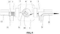
FIG. 5 is a schematic diagram of a state of a water drainage valve when a right drum of a double drum washing machine is drained according to an embodiment. - In the drawings:
- 1. first water drainage valve body; 11. first water inlet; 12. first water outlet; 13. first valve plug;
- 2. second water drainage valve body; 21. second water inlet; 22. second water outlet; 23. second valve plug; 3. motor; 4. turntable; 41. first arc-shaped guide groove; 42. second arc-shaped guide groove; 5. first pull rod; 6. second pull rod; 51. first pull rod hook; 61. second pull rod hook.
- A water drainage valve for a double drum washing machine is provided by this embodiment. As shown in
FIG. 1 and FIG. 2 , the water drainage valve for the double drum washing machine includes a first waterdrainage valve body 1 and a second waterdrainage valve body 2 which are symmetrically disposed with respect to each other. The first waterdrainage valve body 1 is provided with afirst water inlet 11 and afirst water outlet 12, and the second waterdrainage valve body 2 is provided with asecond water inlet 21 and asecond water outlet 22. In one embodiment, thefirst water inlet 11 is connected to a left drum (not shown in the drawings) of the double drum washing machine, and thesecond water inlet 21 is connected to a right drum of the double drum washing machine. When thefirst water inlet 11 is intercommunicated with thefirst water outlet 12, a left outer drum may be drained. When thesecond water inlet 21 is intercommunicated with thesecond water outlet 22, a right outer drum may be drained. Afirst valve plug 13 is disposed between thefirst water inlet 11 and thefirst water outlet 12 of the first waterdrainage valve body 1. Thefirst valve plug 13 is configured to control thefirst water inlet 11 to be intercommunicated or uncommunicated with thesecond water outlet 12. Asecond valve plug 23 is disposed between thesecond water inlet 21 and thesecond water outlet 22 of the second waterdrainage valve body 2. Thesecond valve plug 23 is configured to control thesecond water inlet 21 to be intercommunicated or uncommunicated with thesecond water outlet 22. In one embodiment, thefirst valve plug 13 and thesecond valve plug 23 are connected to a same drive assembly. The drive assembly may drive thefirst valve plug 13 to move to control thefirst water inlet 11 to be intercommunicated with or uncommunicated with thefirst water outlet 12. - In one embodiment, when the
first valve plug 13 is driven to move to a position where thefirst water inlet 11 is intercommunicated with thefirst water outlet 12, thefirst water inlet 11 is uncommunicated with thefirst water outlet 12, that is, water cannot be drained from thefirst water outlet 12. When thefirst valve plug 13 is driven to move away from the position where thefirst water inlet 11 is intercommunicated with thefirst water outlet 12, thefirst water inlet 11 is intercommunicated with thefirst water outlet 12, and the water may enter into thefirst water inlet 11 and be drained from thefirst water outlet 12. - In one embodiment, when the
second valve plug 23 is driven to move to a position where thesecond water inlet 21 is intercommunicated with thesecond water outlet 22, thesecond water inlet 21 is uncommunicated with thesecond water outlet 22, that is, water cannot be drained from thesecond water outlet 22. When thesecond valve plug 23 is driven to move away from the position where thesecond water inlet 21 is intercommunicated with thesecond water outlet 22, thesecond water inlet 21 is intercommunicated with thesecond water outlet 22, and the water may enter into thesecond water inlet 21 and be drained from thesecond water outlet 22. - In this embodiment, when the
first water inlet 11 is intercommunicated with thefirst water outlet 12, thefirst valve plug 13 moves towards the drive assembly. When thesecond water inlet 21 is intercommunicated with thesecond water outlet 22, thesecond valve plug 23 moves towards the drive assembly. - When the drive assembly drives the
first valve plug 13 to move, thesecond valve plug 23 is in a stationary state; when the drive assembly drives thesecond valve plug 23 to move, thefirst valve plug 13 is in a stationary state. That is, when thefirst water inlet 11 is intercommunicated with thefirst water outlet 12 of the first waterdrainage valve body 1, thesecond water inlet 21 is uncommunicated with thesecond water outlet 22 of the second waterdrainage valve body 2; when thesecond water inlet 21 is intercommunicated with thesecond water outlet 22 of the second waterdrainage valve body 2, thefirst water inlet 11 is uncommunicated with thefirst water outlet 12 of the first waterdrainage valve body 1. - In one embodiment, the drive assembly includes a
motor 3. Aturntable 4 is secured to an output end of themotor 3. Theturntable 4 is provided with a first arc-shaped guide groove 41 and a second arc-shaped guide groove 42 symmetrically disposed with respect to each other. The first arc-shaped guide groove 41 and the second arc-shaped guide groove 42 are disposed on a same side of a center of theturntable 4, and a center of the first arc-shaped guide groove 41 and a center of the second arc-shaped guide groove 42 each coincide with the center of theturntable 4. Afirst pull rod 5 is mounted within the first arc-shaped guide groove 41, and asecond pull rod 6 is mounted within the second arc-shaped guide groove 42. Thefirst pull rod 5 and thesecond pull rod 6 are symmetrically disposed. One end of thefirst pull rod 5 is provided with a firstpull rod hook 51, and the firstpull rod hook 51 is disposed within the first arc-shapedguide groove 41 and movable within the first arc-shapedguide groove 41. The other end of thefirst pull rod 5 without thefirst hook 51 penetrates through the first waterdrainage valve body 1 and is connected to thefirst valve plug 13 inside the first waterdrainage valve body 1. One end of thesecond pull rod 6 is provided with a secondpull rod hook 61. The secondpull rod hook 61 is disposed within the second arc-shapedguide groove 42 and movable within the second arc-shapedguide groove 42. The other end of thesecond pull rod 6 without thesecond hook 61 penetrates through the second waterdrainage valve body 2 and is connected to thesecond valve plug 23 inside the second waterdrainage valve body 2. - When the
first water inlet 11 is uncommunicated with thefirst water outlet 12 of the first waterdrainage valve body 1 and thesecond water inlet 21 is uncommunicated with thesecond water outlet 22 of the second waterdrainage valve body 2, a center of the firstpull rod hook 51 of thefirst pull rod 5, a center of the secondpull rod hook 61 of thesecond pull rod 6 and the center of theturntable 4 are located on a same straight line. - In one embodiment, when the
motor 3 drives theturntable 4 to rotate, the first arc-shapedguide groove 41 drives the firstpull rod hook 51 within the first arc-shapedguide groove 41 to move, at this moment, the firstpull rod hook 51 drives thefirst pull rod 5 connected to the firstpull rod hook 51 to rotate along with theturntable 4, and thefirst pull rod 5 drives thefirst valve plug 13 to move towards theturntable 4, so that thefirst water inlet 11 is intercommunicated with thefirst water outlet 12 of the first waterdrainage valve body 1 where thefirst valve plug 13 is located. The secondpull rod hook 61 within the second arc-shapedguide groove 42 is not driven by the second arc-shapedguide groove 42 to move, that is, thesecond valve plug 23 connected to thesecond pull rod 6 connected to the secondpull rod hook 61 is not driven to move, so that thesecond water inlet 21 is uncommunicated with thesecond water outlet 22 of the second waterdrainage valve body 2 where thesecond valve plug 23 is located. That is, when theturntable 4 in this embodiment rotates, theturntable 4 only drives one of the pull rods to move, thereby achieving separate intercommunication between a water inlet and a water outlet of the two water drainage valve bodies, that is, separately draining water out of each drum of the double drum washing machine. - In this embodiment, the
first water inlet 11 and thefirst water outlet 12 of the first waterdrainage valve body 1 are perpendicular to each other, so that thefirst valve plug 13 may control thefirst water inlet 11 to be intercommunicated or uncommunicated with thefirst water outlet 12. And thesecond water inlet 21 and thesecond water outlet 22 of the second waterdrainage valve body 2 are perpendicular to each other, so that thesecond valve plug 23 may control thesecond water inlet 21 to be intercommunicated or uncommunicated with or thesecond water outlet 22, achieving smoother water drainage. - In this embodiment, the
motor 3 may rotate in two directions to generate three positional states. - That is, when two drums of the double drum washing machine are drained separately, the
first water inlet 11 is intercommunicated with thefirst water outlet 12 of the first waterdrainage valve body 1 and thesecond water inlet 21 is uncommunicated with thesecond water outlet 22 of the second waterdrainage valve body 2, or thefirst water inlet 11 is uncommunicated with thefirst water outlet 12 of the first waterdrainage valve body 1 and thesecond water inlet 21 is intercommunicated with thesecond water outlet 22 of the second waterdrainage valve body 2; when the two drums are not drained, thefirst water inlet 11 is uncommunicated with thefirst water outlet 12 of the first waterdrainage valve body 1 and thesecond water inlet 21 is uncommunicated with thesecond water outlet 22 of the second waterdrainage valve body 2. - In one embodiment, the water drainage valve for the double drum washing machine in this embodiment has working states described below.
- As shown in
FIG. 3 , when the double drum washing machine is in a non-drainage state, thefirst water inlet 11 is uncommunicated with thefirst water outlet 12 of the first waterdrainage valve body 1 of the water drainage valve, and thesecond water inlet 21 is uncommunicated with thesecond water outlet 22 of the second waterdrainage valve body 2, so that neither of the two drums is drained. - As shown in
FIG. 4 , when one drum needs to be drained, for example, the one drum is connected to thefirst water inlet 11 of the left first waterdrainage valve body 1 shown inFIG. 4 , and themotor 3 rotates counterclockwise and drives thefirst valve plug 13 of the first waterdrainage valve body 1 to move to enable thefirst water inlet 11 to be intercommunicated with thefirst water outlet 12 of the first waterdrainage valve body 1 until themotor 3 rotates to a position shown inFIG. 4 . At this moment, water in the one drum begins to be drained and the state is maintained until the water in the one drum has been drained. Then themotor 3 rotates clockwise and drives thefirst valve plug 13 to move to uncommunicate thefirst water inlet 11 with thefirst water outlet 12 of the left first waterdrainage valve body 1. At this time, the one drum stops being drained and thefirst valve plug 13 returns to its initial position. In this process, thesecond pull rod 6 connected to thesecond valve plug 23 inside the right second waterdrainage valve body 2 only slides with respect to theturntable 4 and is not driven, so that thesecond valve plug 23 inside the right second waterdrainage valve body 2 always disconnects thesecond water inlet 21 from thesecond water outlet 22 of the right second waterdrainage valve body 2. - As shown in
FIG. 5 , when the right drum needs to be drained, thesecond water inlet 21 needs to be intercommunicated with thesecond water outlet 22 of the right second waterdrainage valve body 2, and themotor 3 rotates clockwise and drives thesecond valve plug 23 of the right second waterdrainage valve body 2 to move to enable thesecond water inlet 21 to be intercommunicated with thesecond water outlet 22 of the right second waterdrainage valve body 2 until themotor 3 rotates to a position shown inFIG. 5 . At this moment, water in the right drum begins to be drained and the state is maintained until the water in the right drum has been drained. Then themotor 3 rotates counterclockwise and drives thesecond valve plug 23 to move to uncommunicate thesecond water inlet 21 with thesecond water outlet 22 of the right second waterdrainage valve body 2. At this moment, the right drum stops being drained and thesecond valve plug 23 returns to its initial position. In this process, thefirst pull rod 5 connected to thefirst valve plug 13 inside the left first waterdrainage valve body 1 only slides with respect to theturntable 4 and is not driven, so that thefirst valve plug 13 inside the left first waterdrainage valve body 1 always uncommunicates thefirst water inlet 11 with thefirst water outlet 12 of the left first waterdrainage valve body 1. - It should be noted that in this embodiment, when the first water
drainage valve body 1 of the water drainage valve opens or closes, the firstpull rod hook 51 of thefirst pull rod 5 should always move within the first arc-shapedguide groove 41 of theturntable 4, and an arc length of the first arc-shapedguide groove 41 should ensure that thefirst valve plug 13 is fully opened (that is, thefirst water inlet 11 is fully intercommunicated with the first water outlet 12). When the second waterdrainage valve body 2 of the water drainage valve opens or closes, the secondpull rod hook 61 of thesecond pull rod 6 should always move within the second arc-shapedguide groove 42 of theturntable 4, and an arc length of the second arc-shapedguide groove 42 should ensure that thesecond valve plug 23 is fully opened (that is, thesecond water inlet 21 is fully intercommunicated with the second water outlet 22). - A double drum washing machine includes the above-mentioned water drainage valve through which outer drums can be separately drained.
- The water drainage valve for a double drum washing machine in the present disclosure solves the problem in the related art that multiple water drainage systems of a multi-drum washing machine have complicated structures and waste space, and a single water drainage system of the multi-drum washing machine fails to drain water separately out of each outer drum.
Claims (13)
- A water drainage valve for a double drum washing machine, comprising:a first water drainage valve body (1) connected to a first outer drum and a second water drainage valve body (2) connected to a second outer drum;a first valve plug (13) inside the first water drainage valve body (1) and a second valve plug (23) inside the second water drainage valve body (2); anda drive assembly connected to the first valve plug (13) and the second valve plug (23), wherein the drive assembly is configured to drive the first valve plug (13) to move so as to control the first water drainage valve body (1) to open or close and drive the second valve plug (23) to move so as to control the second water drainage valve body (2) to open or close; and the first water drainage valve body (1) is in a closed state when the second water drainage valve body (2) is in an open state.
- The water drainage valve for a double drum washing machine of claim 1, wherein
the drive assembly is configured to drive the first valve plug (13) to move so as to control the first water drainage valve body (1) to open or close and drive the second valve plug (23) to move so as to control the second water drainage valve body (2) to open or close; and the second water drainage valve body (2) is in a closed state when the first water drainage valve body (1) is in an open state. - The water drainage valve for a double drum washing machine of claim 1 or 2, wherein
the first water drainage valve body (1) is provided with a first water inlet (11) and a first water outlet (12), the first valve plug (13) is disposed between the first water inlet (11) and the first water outlet (12), and the drive assembly is configured to drive the first valve plug (13) to move so as to control the first water inlet (11) to be intercommunicated or uncommunicated with the first water outlet (12); and
the second water drainage valve body (2) is provided with a second water inlet (21) and a second water outlet (22), the second valve plug (23) is disposed between the second water inlet (21) and the second water outlet (22), and the drive assembly is configured to drive the second valve plug (23) to move so as to control the second water inlet (21) to be intercommunicated or uncommunicated with the second water outlet (22). - The water drainage valve for a double drum washing machine of claim 3, wherein
the drive assembly comprises a motor (3), a turntable (4) secured to an output end of the motor (3), a first pull rod (5) connected to the first valve plug (13), and a second pull rod (6) connected to the second valve plug (23); wherein
the turntable (4) is configured to, in condition that the turntable (4) rotates, only drive the first pull rod (5) to move, so that the first pull rod (5) drives the first valve plug (13) connected to the first pull rod (5) to move so as to control the first water inlet (11) to be intercommunicated with the first water outlet (12). - The water drainage valve for a double drum washing machine of claim 4, wherein the turntable (4) is configured to, in condition that the turntable (4) rotates, only drive the second pull rod (6) to move, so that the second pull rod (6) drives the second valve plug (23) connected to the second pull rod (6) to move so as to control the second water inlet (21) to be intercommunicated with the second water outlet (22).
- The water drainage valve for a double drum washing machine of claim 4 or 5, wherein
the turntable (4) is provided with a first arc-shaped guide groove (41) and a second arc-shaped guide groove (42) symmetrically disposed with respect to each other, the first arc-shaped guide groove (41) and the second arc-shaped guide groove (42) are disposed on a same side of a center of the turntable (4), one end of the first pull rod (5) is disposed within the first arc-shaped guide groove (41) and movable when driven by the first arc-shaped guide groove (41), and one end of the second pull rod (6) is disposed within the second arc-shaped guide groove (42) and movable when driven by the second arc-shaped guide groove (42). - The water drainage valve for a double drum washing machine of claim 6, wherein
the first arc-shaped guide groove (41), the second arc-shaped guide groove (42) and the turntable (4) are concentrically arranged. - The water drainage valve for a double drum washing machine of claim 7, wherein
the one end of the first pull rod (5) within the first arc-shaped guide groove (41) is provided with a first pull rod hook (51), and the first pull rod hook (51) is disposed within the first arc-shaped guide groove (41) and movable within the first arc-shaped guide groove (41); and the one end of the second pull rod (6) within the second arc-shaped guide groove (42) is provided with a second pull rod hook (61), and the second pull rod hook (61) is disposed within the second arc-shaped guide groove (42) and movable within the second arc-shaped guide groove (42). - The water drainage valve for a double drum washing machine of claim 8, wherein
when the first water drainage valve body (1) and the second water drainage valve body (2) each are in the closed state, a center of the first pull rod hook (51), a center of the second pull rod hook (61), and the center of the turntable (4) are located on a same straight line. - The water drainage valve for a double drum washing machine of claim 9, wherein
the second pull rod hook (61) within the second arc-shaped guide groove (42) is configured to, in condition that the first arc-shaped guide groove (41) drives the first pull rod hook (51) within the first arc-shaped guide groove (41) to move, be not driven by the second arc-shaped guide groove (42) to move. - The water drainage valve for a double drum washing machine of claim 9, wherein
the first pull rod hook (51) within the first arc-shaped guide groove (41) is configured to, in condition that the second arc-shaped guide groove (42) drives the second pull rod hook (61) within the second arc-shaped guide groove (42) to move, be not driven by the first arc-shaped guide groove (41) to move. - The water drainage valve for a double drum washing machine of claim 1 or 2, wherein
a first water inlet (11) and a first water outlet (12) of the first water drainage valve body (1) are perpendicular to each other; and a first water inlet (21) and a second water outlet (22) of the second water drainage valve body (2) are perpendicular to each other. - A double drum washing machine, comprising a water drainage valve of any one of claims 1 to 12.
Applications Claiming Priority (2)
| Application Number | Priority Date | Filing Date | Title |
|---|---|---|---|
| CN201710242215.8A CN106939500B (en) | 2017-04-12 | 2017-04-12 | Drainage valve of double drum washing machine and double drum washing machine using the same |
| PCT/CN2018/082768 WO2018188623A1 (en) | 2017-04-12 | 2018-04-12 | Water drainage valve for dual-drum clothes washing machine, and dual-drum clothes washing machine using said water drainage valve |
Publications (3)
| Publication Number | Publication Date |
|---|---|
| EP3611299A1 true EP3611299A1 (en) | 2020-02-19 |
| EP3611299A4 EP3611299A4 (en) | 2020-12-16 |
| EP3611299B1 EP3611299B1 (en) | 2023-05-10 |
Family
ID=59463625
Family Applications (1)
| Application Number | Title | Priority Date | Filing Date |
|---|---|---|---|
| EP18784874.2A Active EP3611299B1 (en) | 2017-04-12 | 2018-04-12 | Water drainage valve for dual-drum clothes washing machine, and dual-drum clothes washing machine using said water drainage valve |
Country Status (4)
| Country | Link |
|---|---|
| US (1) | US11390976B2 (en) |
| EP (1) | EP3611299B1 (en) |
| CN (1) | CN106939500B (en) |
| WO (1) | WO2018188623A1 (en) |
Families Citing this family (8)
| Publication number | Priority date | Publication date | Assignee | Title |
|---|---|---|---|---|
| CN106939500B (en) | 2017-04-12 | 2021-11-02 | 合肥海尔滚筒洗衣机有限公司 | Drainage valve of double drum washing machine and double drum washing machine using the same |
| CN110332340A (en) * | 2019-07-29 | 2019-10-15 | 深圳市科谱森精密技术有限公司 | Multi-outlet valve with adjustable ventilation and apnea cycles |
| CN110607677A (en) * | 2019-10-12 | 2019-12-24 | 宁波凯波智能熨烫电器制造有限公司 | Multipurpose steam brush with at least two ironing sides |
| CN112797195B (en) * | 2021-01-06 | 2022-03-01 | 宁波方太厨具有限公司 | Water mixing valve and water heater |
| WO2023207508A1 (en) * | 2022-04-26 | 2023-11-02 | 青岛海尔洗涤电器有限公司 | Washing apparatus, switching device, and method for controlling washing apparatus |
| CN115058861B (en) * | 2022-07-01 | 2024-10-25 | 无锡小天鹅电器有限公司 | Clothes treatment equipment and control method |
| FR3162730A1 (en) * | 2024-05-31 | 2025-12-05 | Airbus Operations (S.A.S) | Air sampling system for an aircraft |
| CN118686957B (en) * | 2024-08-27 | 2025-01-03 | 江苏泰阀阀门科技有限公司 | Leak-proof valve |
Family Cites Families (34)
| Publication number | Priority date | Publication date | Assignee | Title |
|---|---|---|---|---|
| US262632A (en) * | 1882-08-15 | Faucet | ||
| US701509A (en) * | 1901-09-25 | 1902-06-03 | Homestead Valve Mfg Co | Valve. |
| US766116A (en) * | 1903-02-24 | 1904-07-26 | Pierce Crouch Engine Company | Starting attachment for explosive-engines. |
| US1078939A (en) * | 1912-08-03 | 1913-11-18 | William H Miller | Combination-faucet. |
| US1203321A (en) * | 1914-02-05 | 1916-10-31 | Frederick Fosdick | Steam-engine valve mechanism. |
| US1443539A (en) * | 1921-09-03 | 1923-01-30 | Charles F Jansen | Mixing valve |
| US1553372A (en) * | 1923-07-19 | 1925-09-15 | Grover S Eble | Valve |
| US1742669A (en) * | 1927-02-23 | 1930-01-07 | James C Ross | Duplex faucet |
| US1840961A (en) * | 1928-02-10 | 1932-01-12 | Kuenzler Otto | Mixing faucet |
| US2076842A (en) * | 1934-05-02 | 1937-04-13 | Jacob A Stryker | Fluid control device |
| US2417158A (en) * | 1945-05-16 | 1947-03-11 | Speakman Co | Mixing valve |
| US2504610A (en) * | 1945-12-26 | 1950-04-18 | Richard H Wolf | Swing spout faucet |
| US2464458A (en) * | 1947-10-15 | 1949-03-15 | Keepers M Newcomer | Liquid mixing valve |
| US2800137A (en) * | 1954-06-02 | 1957-07-23 | Speakman Co | Mixing valves |
| US3128788A (en) * | 1959-08-26 | 1964-04-14 | Drallim Ltd | Fluid switching valves |
| US3353554A (en) * | 1965-09-15 | 1967-11-21 | Drallim Ltd | Fluid control valves |
| US3403700A (en) * | 1966-05-09 | 1968-10-01 | Meynell & Sons Ltd | Fluid mixing valve with adjustable cam actuator |
| US3638678A (en) * | 1970-05-06 | 1972-02-01 | Symmons Ind Inc | Duplex valve |
| DE3606897A1 (en) | 1986-03-03 | 1987-09-10 | Aweco Kunststofftech Geraete | SAFETY VALVE FOR HOME APPLIANCES |
| US4865078A (en) * | 1989-03-01 | 1989-09-12 | Cla-Val Co. | Manual control valve |
| TW244368B (en) * | 1992-11-06 | 1995-04-01 | Fujikin Kk | |
| IT1281406B1 (en) * | 1995-12-13 | 1998-02-18 | Eltek Spa | ANTI-FLOODING SAFETY DEVICE FOR WASHING MACHINES. |
| US6206028B1 (en) * | 2000-06-19 | 2001-03-27 | The Keeney Manufacturing Company | Universal multi-path control valve system |
| US7373953B2 (en) * | 2003-08-11 | 2008-05-20 | Oatey Co. | Valve assembly |
| US8555923B1 (en) * | 2003-08-11 | 2013-10-15 | Oatey Co. | Valve assembly |
| US20060117811A1 (en) * | 2004-12-06 | 2006-06-08 | Kinnetz Roger E | Liquid detergent dispensing system for automatic washer |
| US8375970B2 (en) * | 2008-11-10 | 2013-02-19 | Access Business Group International Llc | Valve system |
| WO2013129140A1 (en) * | 2012-02-27 | 2013-09-06 | Ckd株式会社 | Lever type switching valve |
| WO2014156067A1 (en) * | 2013-03-29 | 2014-10-02 | パナソニック株式会社 | Washing machine |
| CN203516840U (en) * | 2013-09-24 | 2014-04-02 | 广东新宝电器股份有限公司 | Two-inlet two-outlet valve |
| CN203625679U (en) | 2013-11-15 | 2014-06-04 | 海尔集团公司 | Drainage component of double-roller washing machine |
| CN104652085B (en) * | 2013-11-19 | 2018-10-12 | 青岛海尔滚筒洗衣机有限公司 | A kind of Double-rotary drum washing machine |
| CN105986427B (en) * | 2015-01-27 | 2019-10-01 | 青岛海尔洗衣机有限公司 | A kind of washing machine double-ended draining pump |
| CN106939500B (en) | 2017-04-12 | 2021-11-02 | 合肥海尔滚筒洗衣机有限公司 | Drainage valve of double drum washing machine and double drum washing machine using the same |
-
2017
- 2017-04-12 CN CN201710242215.8A patent/CN106939500B/en active Active
-
2018
- 2018-04-12 EP EP18784874.2A patent/EP3611299B1/en active Active
- 2018-04-12 US US16/605,166 patent/US11390976B2/en active Active
- 2018-04-12 WO PCT/CN2018/082768 patent/WO2018188623A1/en not_active Ceased
Also Published As
| Publication number | Publication date |
|---|---|
| EP3611299A4 (en) | 2020-12-16 |
| US20210102331A1 (en) | 2021-04-08 |
| CN106939500B (en) | 2021-11-02 |
| US11390976B2 (en) | 2022-07-19 |
| EP3611299B1 (en) | 2023-05-10 |
| WO2018188623A1 (en) | 2018-10-18 |
| CN106939500A (en) | 2017-07-11 |
Similar Documents
| Publication | Publication Date | Title |
|---|---|---|
| US11390976B2 (en) | Water drainage valve for dual-drum clothes washing machine, and dual-drum clothes washing machine using water drainage valve | |
| CN207672145U (en) | A kind of groove body cover board automatic cover-turning mechanism | |
| CN104647800B (en) | A kind of fully automatic hydraulic essence impact machine high and low pressure translation function optimizes hydraulic system | |
| CN208764023U (en) | A kind of hydraulic cylinder and hydraulic system | |
| CN204692702U (en) | Wireless remote intelligent actuator | |
| CN204592409U (en) | A kind of straight-through two switch spool | |
| CN206844071U (en) | A kind of new shared two-way rope stretching opening/closing system of reel | |
| CN203124311U (en) | Cleaning device | |
| CN107387473B (en) | Tandem channel-borrowing type multipath hydraulic control device | |
| CN107697616B (en) | A kind of magnetic drives the hopper of the double outlet automatic switchovers of formula | |
| CN208364517U (en) | Multistage pressure flow asks for valve | |
| CN105513859A (en) | Protective structure and switch cabinet with same | |
| CN203438405U (en) | Concrete mixer pouring port automatic opening device | |
| CN212225148U (en) | Non-excavation rig holder | |
| CN204094801U (en) | The wrist body of motor direct-connected | |
| CN204375602U (en) | Door interlock under solid insulation ring main unit | |
| CN208185585U (en) | A kind of control structure of Leading valve | |
| CN108644174A (en) | A kind of multistage pressure flow asks for valve | |
| CN207283442U (en) | Multi-motor control system and financial self-service equipment | |
| CN205069434U (en) | Cubical switchboard interlock and have its interlocking switch cabinet | |
| CN208055644U (en) | A kind of textile machinery overflow dyeing machine | |
| CN203947308U (en) | The fur dyeing machine of automatic draining | |
| CN205800131U (en) | A kind of mechanical safety device of injection machine | |
| CN102678678A (en) | Hydraulic emergency operation module | |
| CN204265998U (en) | High-performance snail rapid steamer |
Legal Events
| Date | Code | Title | Description |
|---|---|---|---|
| STAA | Information on the status of an ep patent application or granted ep patent |
Free format text: STATUS: THE INTERNATIONAL PUBLICATION HAS BEEN MADE |
|
| PUAI | Public reference made under article 153(3) epc to a published international application that has entered the european phase |
Free format text: ORIGINAL CODE: 0009012 |
|
| STAA | Information on the status of an ep patent application or granted ep patent |
Free format text: STATUS: REQUEST FOR EXAMINATION WAS MADE |
|
| 17P | Request for examination filed |
Effective date: 20191112 |
|
| AK | Designated contracting states |
Kind code of ref document: A1 Designated state(s): AL AT BE BG CH CY CZ DE DK EE ES FI FR GB GR HR HU IE IS IT LI LT LU LV MC MK MT NL NO PL PT RO RS SE SI SK SM TR |
|
| AX | Request for extension of the european patent |
Extension state: BA ME |
|
| DAV | Request for validation of the european patent (deleted) | ||
| DAX | Request for extension of the european patent (deleted) | ||
| A4 | Supplementary search report drawn up and despatched |
Effective date: 20201117 |
|
| RIC1 | Information provided on ipc code assigned before grant |
Ipc: F16K 31/528 20060101ALI20201111BHEP Ipc: D06F 31/00 20060101ALI20201111BHEP Ipc: F16K 11/16 20060101ALI20201111BHEP Ipc: D06F 39/08 20060101AFI20201111BHEP |
|
| GRAP | Despatch of communication of intention to grant a patent |
Free format text: ORIGINAL CODE: EPIDOSNIGR1 |
|
| STAA | Information on the status of an ep patent application or granted ep patent |
Free format text: STATUS: GRANT OF PATENT IS INTENDED |
|
| INTG | Intention to grant announced |
Effective date: 20221110 |
|
| GRAS | Grant fee paid |
Free format text: ORIGINAL CODE: EPIDOSNIGR3 |
|
| GRAA | (expected) grant |
Free format text: ORIGINAL CODE: 0009210 |
|
| STAA | Information on the status of an ep patent application or granted ep patent |
Free format text: STATUS: THE PATENT HAS BEEN GRANTED |
|
| AK | Designated contracting states |
Kind code of ref document: B1 Designated state(s): AL AT BE BG CH CY CZ DE DK EE ES FI FR GB GR HR HU IE IS IT LI LT LU LV MC MK MT NL NO PL PT RO RS SE SI SK SM TR |
|
| REG | Reference to a national code |
Ref country code: GB Ref legal event code: FG4D |
|
| REG | Reference to a national code |
Ref country code: AT Ref legal event code: REF Ref document number: 1566774 Country of ref document: AT Kind code of ref document: T Effective date: 20230515 Ref country code: CH Ref legal event code: EP |
|
| REG | Reference to a national code |
Ref country code: DE Ref legal event code: R096 Ref document number: 602018049681 Country of ref document: DE |
|
| REG | Reference to a national code |
Ref country code: IE Ref legal event code: FG4D |
|
| REG | Reference to a national code |
Ref country code: LT Ref legal event code: MG9D |
|
| REG | Reference to a national code |
Ref country code: NL Ref legal event code: MP Effective date: 20230510 |
|
| REG | Reference to a national code |
Ref country code: AT Ref legal event code: MK05 Ref document number: 1566774 Country of ref document: AT Kind code of ref document: T Effective date: 20230510 |
|
| PG25 | Lapsed in a contracting state [announced via postgrant information from national office to epo] |
Ref country code: SE Free format text: LAPSE BECAUSE OF FAILURE TO SUBMIT A TRANSLATION OF THE DESCRIPTION OR TO PAY THE FEE WITHIN THE PRESCRIBED TIME-LIMIT Effective date: 20230510 Ref country code: PT Free format text: LAPSE BECAUSE OF FAILURE TO SUBMIT A TRANSLATION OF THE DESCRIPTION OR TO PAY THE FEE WITHIN THE PRESCRIBED TIME-LIMIT Effective date: 20230911 Ref country code: NO Free format text: LAPSE BECAUSE OF FAILURE TO SUBMIT A TRANSLATION OF THE DESCRIPTION OR TO PAY THE FEE WITHIN THE PRESCRIBED TIME-LIMIT Effective date: 20230810 Ref country code: NL Free format text: LAPSE BECAUSE OF FAILURE TO SUBMIT A TRANSLATION OF THE DESCRIPTION OR TO PAY THE FEE WITHIN THE PRESCRIBED TIME-LIMIT Effective date: 20230510 Ref country code: ES Free format text: LAPSE BECAUSE OF FAILURE TO SUBMIT A TRANSLATION OF THE DESCRIPTION OR TO PAY THE FEE WITHIN THE PRESCRIBED TIME-LIMIT Effective date: 20230510 Ref country code: AT Free format text: LAPSE BECAUSE OF FAILURE TO SUBMIT A TRANSLATION OF THE DESCRIPTION OR TO PAY THE FEE WITHIN THE PRESCRIBED TIME-LIMIT Effective date: 20230510 |
|
| PG25 | Lapsed in a contracting state [announced via postgrant information from national office to epo] |
Ref country code: RS Free format text: LAPSE BECAUSE OF FAILURE TO SUBMIT A TRANSLATION OF THE DESCRIPTION OR TO PAY THE FEE WITHIN THE PRESCRIBED TIME-LIMIT Effective date: 20230510 Ref country code: PL Free format text: LAPSE BECAUSE OF FAILURE TO SUBMIT A TRANSLATION OF THE DESCRIPTION OR TO PAY THE FEE WITHIN THE PRESCRIBED TIME-LIMIT Effective date: 20230510 Ref country code: LV Free format text: LAPSE BECAUSE OF FAILURE TO SUBMIT A TRANSLATION OF THE DESCRIPTION OR TO PAY THE FEE WITHIN THE PRESCRIBED TIME-LIMIT Effective date: 20230510 Ref country code: LT Free format text: LAPSE BECAUSE OF FAILURE TO SUBMIT A TRANSLATION OF THE DESCRIPTION OR TO PAY THE FEE WITHIN THE PRESCRIBED TIME-LIMIT Effective date: 20230510 Ref country code: IS Free format text: LAPSE BECAUSE OF FAILURE TO SUBMIT A TRANSLATION OF THE DESCRIPTION OR TO PAY THE FEE WITHIN THE PRESCRIBED TIME-LIMIT Effective date: 20230910 Ref country code: HR Free format text: LAPSE BECAUSE OF FAILURE TO SUBMIT A TRANSLATION OF THE DESCRIPTION OR TO PAY THE FEE WITHIN THE PRESCRIBED TIME-LIMIT Effective date: 20230510 Ref country code: GR Free format text: LAPSE BECAUSE OF FAILURE TO SUBMIT A TRANSLATION OF THE DESCRIPTION OR TO PAY THE FEE WITHIN THE PRESCRIBED TIME-LIMIT Effective date: 20230811 |
|
| PG25 | Lapsed in a contracting state [announced via postgrant information from national office to epo] |
Ref country code: FI Free format text: LAPSE BECAUSE OF FAILURE TO SUBMIT A TRANSLATION OF THE DESCRIPTION OR TO PAY THE FEE WITHIN THE PRESCRIBED TIME-LIMIT Effective date: 20230510 |
|
| PG25 | Lapsed in a contracting state [announced via postgrant information from national office to epo] |
Ref country code: SK Free format text: LAPSE BECAUSE OF FAILURE TO SUBMIT A TRANSLATION OF THE DESCRIPTION OR TO PAY THE FEE WITHIN THE PRESCRIBED TIME-LIMIT Effective date: 20230510 |
|
| PG25 | Lapsed in a contracting state [announced via postgrant information from national office to epo] |
Ref country code: SM Free format text: LAPSE BECAUSE OF FAILURE TO SUBMIT A TRANSLATION OF THE DESCRIPTION OR TO PAY THE FEE WITHIN THE PRESCRIBED TIME-LIMIT Effective date: 20230510 Ref country code: SK Free format text: LAPSE BECAUSE OF FAILURE TO SUBMIT A TRANSLATION OF THE DESCRIPTION OR TO PAY THE FEE WITHIN THE PRESCRIBED TIME-LIMIT Effective date: 20230510 Ref country code: RO Free format text: LAPSE BECAUSE OF FAILURE TO SUBMIT A TRANSLATION OF THE DESCRIPTION OR TO PAY THE FEE WITHIN THE PRESCRIBED TIME-LIMIT Effective date: 20230510 Ref country code: EE Free format text: LAPSE BECAUSE OF FAILURE TO SUBMIT A TRANSLATION OF THE DESCRIPTION OR TO PAY THE FEE WITHIN THE PRESCRIBED TIME-LIMIT Effective date: 20230510 Ref country code: DK Free format text: LAPSE BECAUSE OF FAILURE TO SUBMIT A TRANSLATION OF THE DESCRIPTION OR TO PAY THE FEE WITHIN THE PRESCRIBED TIME-LIMIT Effective date: 20230510 Ref country code: CZ Free format text: LAPSE BECAUSE OF FAILURE TO SUBMIT A TRANSLATION OF THE DESCRIPTION OR TO PAY THE FEE WITHIN THE PRESCRIBED TIME-LIMIT Effective date: 20230510 |
|
| REG | Reference to a national code |
Ref country code: DE Ref legal event code: R097 Ref document number: 602018049681 Country of ref document: DE |
|
| PLBE | No opposition filed within time limit |
Free format text: ORIGINAL CODE: 0009261 |
|
| STAA | Information on the status of an ep patent application or granted ep patent |
Free format text: STATUS: NO OPPOSITION FILED WITHIN TIME LIMIT |
|
| 26N | No opposition filed |
Effective date: 20240213 |
|
| PG25 | Lapsed in a contracting state [announced via postgrant information from national office to epo] |
Ref country code: SI Free format text: LAPSE BECAUSE OF FAILURE TO SUBMIT A TRANSLATION OF THE DESCRIPTION OR TO PAY THE FEE WITHIN THE PRESCRIBED TIME-LIMIT Effective date: 20230510 |
|
| PG25 | Lapsed in a contracting state [announced via postgrant information from national office to epo] |
Ref country code: SI Free format text: LAPSE BECAUSE OF FAILURE TO SUBMIT A TRANSLATION OF THE DESCRIPTION OR TO PAY THE FEE WITHIN THE PRESCRIBED TIME-LIMIT Effective date: 20230510 |
|
| PG25 | Lapsed in a contracting state [announced via postgrant information from national office to epo] |
Ref country code: BG Free format text: LAPSE BECAUSE OF FAILURE TO SUBMIT A TRANSLATION OF THE DESCRIPTION OR TO PAY THE FEE WITHIN THE PRESCRIBED TIME-LIMIT Effective date: 20230510 |
|
| PG25 | Lapsed in a contracting state [announced via postgrant information from national office to epo] |
Ref country code: MC Free format text: LAPSE BECAUSE OF FAILURE TO SUBMIT A TRANSLATION OF THE DESCRIPTION OR TO PAY THE FEE WITHIN THE PRESCRIBED TIME-LIMIT Effective date: 20230510 |
|
| PG25 | Lapsed in a contracting state [announced via postgrant information from national office to epo] |
Ref country code: MC Free format text: LAPSE BECAUSE OF FAILURE TO SUBMIT A TRANSLATION OF THE DESCRIPTION OR TO PAY THE FEE WITHIN THE PRESCRIBED TIME-LIMIT Effective date: 20230510 Ref country code: BG Free format text: LAPSE BECAUSE OF FAILURE TO SUBMIT A TRANSLATION OF THE DESCRIPTION OR TO PAY THE FEE WITHIN THE PRESCRIBED TIME-LIMIT Effective date: 20230510 |
|
| REG | Reference to a national code |
Ref country code: CH Ref legal event code: PL |
|
| PG25 | Lapsed in a contracting state [announced via postgrant information from national office to epo] |
Ref country code: LU Free format text: LAPSE BECAUSE OF NON-PAYMENT OF DUE FEES Effective date: 20240412 |
|
| REG | Reference to a national code |
Ref country code: BE Ref legal event code: MM Effective date: 20240430 |
|
| PG25 | Lapsed in a contracting state [announced via postgrant information from national office to epo] |
Ref country code: LU Free format text: LAPSE BECAUSE OF NON-PAYMENT OF DUE FEES Effective date: 20240412 |
|
| PG25 | Lapsed in a contracting state [announced via postgrant information from national office to epo] |
Ref country code: BE Free format text: LAPSE BECAUSE OF NON-PAYMENT OF DUE FEES Effective date: 20240430 |
|
| PG25 | Lapsed in a contracting state [announced via postgrant information from national office to epo] |
Ref country code: BE Free format text: LAPSE BECAUSE OF NON-PAYMENT OF DUE FEES Effective date: 20240430 Ref country code: CH Free format text: LAPSE BECAUSE OF NON-PAYMENT OF DUE FEES Effective date: 20240430 |
|
| PG25 | Lapsed in a contracting state [announced via postgrant information from national office to epo] |
Ref country code: IE Free format text: LAPSE BECAUSE OF NON-PAYMENT OF DUE FEES Effective date: 20240412 |
|
| PGFP | Annual fee paid to national office [announced via postgrant information from national office to epo] |
Ref country code: DE Payment date: 20250422 Year of fee payment: 8 |
|
| PGFP | Annual fee paid to national office [announced via postgrant information from national office to epo] |
Ref country code: GB Payment date: 20250423 Year of fee payment: 8 |
|
| PGFP | Annual fee paid to national office [announced via postgrant information from national office to epo] |
Ref country code: IT Payment date: 20250424 Year of fee payment: 8 |
|
| PGFP | Annual fee paid to national office [announced via postgrant information from national office to epo] |
Ref country code: FR Payment date: 20250425 Year of fee payment: 8 |
|
| PG25 | Lapsed in a contracting state [announced via postgrant information from national office to epo] |
Ref country code: CY Free format text: LAPSE BECAUSE OF FAILURE TO SUBMIT A TRANSLATION OF THE DESCRIPTION OR TO PAY THE FEE WITHIN THE PRESCRIBED TIME-LIMIT; INVALID AB INITIO Effective date: 20180412 |
|
| PG25 | Lapsed in a contracting state [announced via postgrant information from national office to epo] |
Ref country code: HU Free format text: LAPSE BECAUSE OF FAILURE TO SUBMIT A TRANSLATION OF THE DESCRIPTION OR TO PAY THE FEE WITHIN THE PRESCRIBED TIME-LIMIT; INVALID AB INITIO Effective date: 20180412 |