EP3611138A1 - Production method for optical fiber - Google Patents
Production method for optical fiber Download PDFInfo
- Publication number
- EP3611138A1 EP3611138A1 EP18783900.6A EP18783900A EP3611138A1 EP 3611138 A1 EP3611138 A1 EP 3611138A1 EP 18783900 A EP18783900 A EP 18783900A EP 3611138 A1 EP3611138 A1 EP 3611138A1
- Authority
- EP
- European Patent Office
- Prior art keywords
- optical fiber
- coating layer
- curing
- cooling
- semi
- Prior art date
- Legal status (The legal status is an assumption and is not a legal conclusion. Google has not performed a legal analysis and makes no representation as to the accuracy of the status listed.)
- Granted
Links
Images

Classifications
-
- C—CHEMISTRY; METALLURGY
- C03—GLASS; MINERAL OR SLAG WOOL
- C03B—MANUFACTURE, SHAPING, OR SUPPLEMENTARY PROCESSES
- C03B37/00—Manufacture or treatment of flakes, fibres, or filaments from softened glass, minerals, or slags
- C03B37/01—Manufacture of glass fibres or filaments
- C03B37/02—Manufacture of glass fibres or filaments by drawing or extruding, e.g. direct drawing of molten glass from nozzles; Cooling fins therefor
- C03B37/025—Manufacture of glass fibres or filaments by drawing or extruding, e.g. direct drawing of molten glass from nozzles; Cooling fins therefor from reheated softened tubes, rods, fibres or filaments, e.g. drawing fibres from preforms
- C03B37/027—Fibres composed of different sorts of glass, e.g. glass optical fibres
- C03B37/02718—Thermal treatment of the fibre during the drawing process, e.g. cooling
-
- C—CHEMISTRY; METALLURGY
- C03—GLASS; MINERAL OR SLAG WOOL
- C03C—CHEMICAL COMPOSITION OF GLASSES, GLAZES OR VITREOUS ENAMELS; SURFACE TREATMENT OF GLASS; SURFACE TREATMENT OF FIBRES OR FILAMENTS MADE FROM GLASS, MINERALS OR SLAGS; JOINING GLASS TO GLASS OR OTHER MATERIALS
- C03C25/00—Surface treatment of fibres or filaments made from glass, minerals or slags
- C03C25/10—Coating
- C03C25/12—General methods of coating; Devices therefor
-
- C—CHEMISTRY; METALLURGY
- C03—GLASS; MINERAL OR SLAG WOOL
- C03B—MANUFACTURE, SHAPING, OR SUPPLEMENTARY PROCESSES
- C03B37/00—Manufacture or treatment of flakes, fibres, or filaments from softened glass, minerals, or slags
- C03B37/01—Manufacture of glass fibres or filaments
- C03B37/02—Manufacture of glass fibres or filaments by drawing or extruding, e.g. direct drawing of molten glass from nozzles; Cooling fins therefor
- C03B37/025—Manufacture of glass fibres or filaments by drawing or extruding, e.g. direct drawing of molten glass from nozzles; Cooling fins therefor from reheated softened tubes, rods, fibres or filaments, e.g. drawing fibres from preforms
-
- C—CHEMISTRY; METALLURGY
- C03—GLASS; MINERAL OR SLAG WOOL
- C03C—CHEMICAL COMPOSITION OF GLASSES, GLAZES OR VITREOUS ENAMELS; SURFACE TREATMENT OF GLASS; SURFACE TREATMENT OF FIBRES OR FILAMENTS MADE FROM GLASS, MINERALS OR SLAGS; JOINING GLASS TO GLASS OR OTHER MATERIALS
- C03C25/00—Surface treatment of fibres or filaments made from glass, minerals or slags
- C03C25/10—Coating
- C03C25/104—Coating to obtain optical fibres
- C03C25/106—Single coatings
-
- C—CHEMISTRY; METALLURGY
- C03—GLASS; MINERAL OR SLAG WOOL
- C03C—CHEMICAL COMPOSITION OF GLASSES, GLAZES OR VITREOUS ENAMELS; SURFACE TREATMENT OF GLASS; SURFACE TREATMENT OF FIBRES OR FILAMENTS MADE FROM GLASS, MINERALS OR SLAGS; JOINING GLASS TO GLASS OR OTHER MATERIALS
- C03C25/00—Surface treatment of fibres or filaments made from glass, minerals or slags
- C03C25/10—Coating
- C03C25/24—Coatings containing organic materials
- C03C25/26—Macromolecular compounds or prepolymers
-
- C—CHEMISTRY; METALLURGY
- C03—GLASS; MINERAL OR SLAG WOOL
- C03B—MANUFACTURE, SHAPING, OR SUPPLEMENTARY PROCESSES
- C03B2205/00—Fibre drawing or extruding details
- C03B2205/42—Drawing at high speed, i.e. > 10 m/s
-
- C—CHEMISTRY; METALLURGY
- C03—GLASS; MINERAL OR SLAG WOOL
- C03B—MANUFACTURE, SHAPING, OR SUPPLEMENTARY PROCESSES
- C03B2205/00—Fibre drawing or extruding details
- C03B2205/55—Cooling or annealing the drawn fibre prior to coating using a series of coolers or heaters
Definitions
- the present invention relates to an optical fiber manufacturing method.
- an optical fiber manufacturing method including a drawing step, a coating step, and a curing step has been known.
- the drawing step an optical fiber preform is drawn to form a bare optical fiber.
- a coating layer which is uncured (hereinafter, simply referred to as an uncured coating layer) made of resin is provided on the outer periphery of the bare optical fiber.
- the uncured coating layer is cured.
- a bare optical fiber without the coating layer which is easily damaged passes through the slow-cooling furnace.
- an optical fiber having a liquid uncured coating layer is passed through the coating curing device. If the optical fiber in these states is brought into contact with a pulley or the like for changing the direction, it may cause the reduction of the strength of the optical fiber, and the deformation of the coating layer. Therefore, each device needs to be located directly below the melting furnace of the optical fiber preform.
- Patent Document 1 discloses a non-contact direction changer.
- the non-contact direction changer can change the traveling direction of the optical fiber without bringing its components into contact with the optical fiber.
- the non-contact direction changer it is possible to change the traveling direction of the optical fiber even before the uncured coating layer is formed or the uncured coating layer is completely cured.
- each device can be disposed freely, and the drawing speed can be increased even in a place where there is a space limitation in the height direction.
- Patent Document 1 Japanese Patent No. 5851636
- an ultraviolet-curable resin which can be cured at high speed is generally used.
- an ultraviolet lamp, a UV-LED or the like is employed as the coating curing device.
- the temperature at the time of curing of the resin is a factor that determines the degree of curing and the molecular weight of the resin after curing. For example, if the temperature at the time of curing is too high, the curing may be insufficient or the characteristics such as Young's modulus may deteriorate because the molecular weight of the resin after curing is small.
- the temperature of the resin material may be increased for the purpose of reducing the viscosity of the resin material.
- Increasing the temperature of the resin material to adjust the viscosity may also be a factor to increase the temperature of the uncured coating layer.
- Receiving the heat emitted by an ultraviolet lamp or the like may also be a factor to increase the temperature of the uncured coating layer.
- the present invention has been made in view of such circumstances, and an object of the present invention is to provide a manufacturing method of an optical fiber having a coating layer in a desired state while increasing the drawing speed of the optical fiber.
- an optical fiber manufacturing method includes a drawing step of drawing an optical fiber preform to form a bare optical fiber; a first cooling step of cooling the bare optical fiber; a coating step of providing an uncured coating layer containing a resin precursor on an outer periphery of the bare optical fiber; a first curing step of curing the uncured coating layer to form a semi-cured coating layer; a second curing step of further curing the semi-cured coating layer; and a second cooling step of cooling the semi-cured coating layer by at least one non-contact direction changer between the first curing step and the second curing step.
- the optical fiber manufacturing apparatus 1A includes a drawing unit 10, a first cooling unit 13, a coating unit 30, a first curing unit 40A, non-contact direction changers 20A to 20C, a second curing unit 40B, an outer diameter measurement unit 50, a direction changer 20D, and a winder 90, and the respective units are disposed in this order from the top.
- the drawing unit 10 includes a melting furnace or the like for melting an optical fiber preform.
- the drawing unit 10 forms a bare optical fiber 3.
- the first cooling unit 13 includes a slow-cooling furnace 11 and a cooler 12.
- the slow-cooling furnace 11 is a device for gradually cooling the high temperature bare optical fiber 3 drawn from the melting furnace of the drawing unit 10. By slowly cooling the bare optical fiber 3 by the slow-cooling furnace 11, the transmission loss of the optical fiber can be reduced.
- a cooling cylinder or the like can be employed as the cooler 12, a cooling cylinder or the like.
- the cooling cylinder introduces gas into the cavity of the water-cooled cylinder, and passes the optical fiber through the cavity to cool the optical fiber.
- the gas introduced into the cavity includes helium, nitrogen, carbon dioxide, or a mixed gas thereof.
- the heat transfer rates of helium and nitrogen are different. Therefore, in a case of introducing a mixed gas of helium and nitrogen into the cavity, it is possible to adjust the temperature of the bare optical fiber 3 passing through the cooling cylinder by changing the mixing ratio of these gases.
- the coating unit 30 applies or coats a fluid material (hereinafter, simply referred to as a resin material) containing a resin precursor to the outer periphery of the bare optical fiber 3 by die coating or the like to form an uncured coating layer.
- a fluid material hereinafter, simply referred to as a resin material
- the coating layer in the state before passing through the first curing unit 40A is referred to as "uncured coating layer”
- the coating layer in the state after passing through the first curing unit 40A and before passing through the second curing unit 40B is referred to as "semi-cured coating layer”.
- the coating of the resin material is, for example, a two-layer coating.
- a resin material for a primary coating layer with a low Young's modulus is applied to the inside, and a resin material for a secondary coating layer with a high Young's modulus is applied to the outside.
- an ultraviolet-curable resin such as a urethane acrylate resin can be used as the coating layer.
- the coating unit 30 may be configured to coat a primary coating layer and a secondary coating layer separately, or to coat a primary coating layer and a secondary coating layer simultaneously.
- an element which is in a state where the coating layer is provided on the outer periphery of the bare optical fiber 3 is referred to as an optical fiber.
- the viscosity of the resin material applied to the bare optical fiber 3 by the coating unit 30 needs to be low to some extent.
- the viscosity of the resin material can be reduced by raising the temperature of the resin material. Therefore, the temperature of the resin material to be applied by the coating unit 30 may be previously raised above room temperature, which may be one of the factors causing the temperature of the uncured coating layer to rise. In particular, as the viscosity of the resin material at room temperature is higher, it is necessary to raise the temperature of the resin material when applied by the coating unit 30.
- the coating layer is made of an ultraviolet-curable resin
- an ultraviolet irradiation lamp, a UV-LED, and a curing device in which these are combined may be used as the first curing unit 40A.
- the number of curing devices disposed as the first curing unit 40A may be determined, with the curing degree K of the coating layer that has passed these curing devices as an index.
- the curing degree K in the present embodiment is defined using the gel fraction to be described later.
- the plurality of non-contact direction changers 20A, 20B, 20C are disposed below the first curing unit 40A in this order.
- the non-contact direction changers 20A, 20B, 20C change the traveling directions of the optical fiber by 90°, 180°, and 90°, respectively.
- the non-contact direction changer 20A changes the traveling direction of the optical fiber by about 90° from the downward direction to the horizontal direction.
- the number of installed non-contact direction changers, the installation position, the angle of direction change, or the like may be converted as appropriate.
- the non-contact direction changers 20A to 20C have guide grooves for guiding the bare optical fiber 3 or the optical fiber. In the guide groove, an outlet for fluid (gas) for floating the optical fibers wired along the guide groove is formed.
- the non-contact direction changers 20A to 20C float the optical fiber, without contacting the component with the optical fiber, by spraying gas such as air or helium (He) onto the optical fiber from the outlet.
- gas such as air or helium (He) onto the optical fiber from the outlet.
- the configuration of the non-contact direction changer in the present embodiment is the same as the configuration described in Japanese Patent No. 5851636 , and thus a detailed description is omitted here.
- the amount of gas required to float the optical fiber is, for example, about 100 to 200 L/min.
- the amount of gas is appropriately changed depending on the width of the gas outlet and the like. By adjusting the amount of gas, it is possible to adjust the floating amount of the optical fiber, that is, the passing position of the optical fiber with respect to each component.
- a UV-LED may be used as a curing device for the first curing unit 40A or the second curing unit 40B. Since the irradiation light of the UV-LED has directivity, the area in which the ultraviolet ray can be irradiated is relatively small. Therefore, in order to irradiate ultraviolet ray to the uncured coating layer or the semi-cured coating layer reliably, it is necessary to control the passing position of the optical fiber more strictly. Therefore, a position sensor (not shown) is disposed below the non-contact direction changers 20A to 20C, and the position sensor measures the position of the optical fiber. The amount of gas to be sprayed onto the optical fiber by the non-contact direction changers 20A to 20C is adjusted such that the position of the optical fiber is an appropriate position, based on the measurement result.
- the coating layer is a radical-curable ultraviolet-curable resin which is cured by radical polymerization
- the oxygen concentration of the gas sprayed onto the optical fiber is high, curing failure occurs due to oxygen inhibition. Therefore, the oxygen concentration of the gas sprayed onto the optical fiber by the non-contact direction changers 20A to 20C needs to be controlled to an appropriate value.
- the oxygen concentration of the gas can be adjusted by increasing or decreasing the contents of gases other than oxygen, such as nitrogen contained in the air.
- the non-contact direction changers 20A to 20C in the present embodiment are disposed between the first curing unit 40A and the second curing unit 40B, focusing on the cooling capacity. That is, the non-contact direction changers 20A to 20C constitute the second cooling unit 14 that cools the semi-cured coating layer between the first curing unit 40A and the second curing unit 40B.
- the optical fiber preform is drawn to form a bare optical fiber 3 (drawing step).
- the bare optical fiber 3 is gradually cooled in the slow-cooling furnace 11. Further, the bare optical fiber 3 is cooled to a predetermined temperature by the cooler 12 (first cooling step).
- an uncured coating layer containing a resin precursor is provided on the outer periphery of the bare optical fiber 3 to form an optical fiber (coating step).
- the temperature of the resin material applied as the uncured coating layer is previously raised above room temperature in order to reduce its viscosity.
- the uncured coating layer is cured to become a semi-cured coating layer (first curing step).
- the semi-cured coating layer of the optical fiber which passes through the first curing unit 40A is further heated up with the heat or the like emitted by a curing device.
- the semi-cured coating layer is cooled while changing the traveling direction of the optical fiber by the non-contact direction changers 20A to 20C of the second cooling unit 14 (second cooling step).
- the semi-cured coating layer is further cured (second curing step).
- the outer diameter of the optical fiber is measured.
- direction changer 20D the traveling direction of the optical fiber is changed in a substantially horizontal direction by the direction changer 20D, and the optical fiber is wound by the winder 90.
- direction changers such as a contact-type pulley, can be used as direction changer 20D.
- the present embodiment is different from the first embodiment in the configuration of the second cooling unit 14 and the arrangement of the second curing unit 40B.
- the second cooling unit 14 is disposed at the lowermost portion of the optical fiber manufacturing apparatus 1B.
- the second cooling unit 14 is formed of one non-contact direction changer 20E.
- the non-contact direction changer 20E changes the traveling direction of the optical fiber by about 90° from the downward direction to the horizontal direction.
- the second cooling unit 14, the second curing unit 40B, and the outer diameter measurement unit 50 are disposed at the lowermost portion of the optical fiber manufacturing apparatus 1B. Therefore, compared with the first embodiment, the size in the up-down direction of the entire optical fiber manufacturing apparatus can be reduced.
- optical fiber manufacturing method of the present embodiment will be described in more detail using a specific example.
- Example 1 an optical fiber is manufactured by the optical fiber manufacturing apparatus 1A shown in FIG. 1 .
- the outer diameter of the bare optical fiber 3 as 125 ⁇ m
- the outer diameter of the optical fiber as 250 ⁇ m
- two layers of ultraviolet-curable resin (urethane acrylate) are adopted as the coating layer.
- the drawing speed is 50 m/sec.
- Two ultraviolet irradiation lamps are installed as the first curing unit 40A.
- the second cooling unit 14 three non-contact direction changers 20A, 20B, 20C are installed.
- the three non-contact direction changers 20A, 20B, 20C change the traveling directions of the optical fiber by 90°, 180°, and 90°, respectively.
- the gas sprayed onto the optical fiber by the non-contact direction changers 20A to 20C is air whose oxygen concentration is adjusted to 10%.
- Four ultraviolet irradiation lamps are installed as the second curing unit 40B.
- the coating layer of the optical fiber obtained thereby is cured, and the characteristics of the coating layer is also good.
- the gel fraction is calculated by the following method. First, an optical fiber as a sample is input to a Soxhlet extractor, and Soxhlet extraction is performed using methyl ethyl ketone (MEK) as an extraction solvent, under conditions of a temperature of 90 °C and a time of 240 minutes. Thereafter, the sample is dried at a temperature of 60 °C for 240 minutes. The gel fraction is calculated by dividing the dry weight of the insoluble matter after the extraction by the weight of the sample before extraction.
- MEK methyl ethyl ketone
- the temperature at the time of extraction may be a temperature higher than or equal to the boiling point of MEK, and may be the temperature and time at which extraction of elution is saturated.
- the dry weight may be saturated with respect to the temperature and time of drying.
- the gel fraction increases with the increase of the UV irradiation amount to the coating layer, and saturates at a certain UV irradiation amount.
- the UV irradiation amount is a value obtained by multiplying the UV illuminance (mW/cm 2 ) from each UV irradiation device by each irradiation time (second). Further, the irradiation time in the optical fiber manufacturing apparatus is defined as a value obtained by dividing the distance (m) which the optical fiber in the UV irradiation device passes by the drawing speed (m/sec).
- the relationship between the UV irradiation amount and the gel fraction can be obtained by preparing a plurality of samples by changing the drawing speed, the number of UV irradiation devices, or the UV illuminance, and evaluating the gel fraction of each sample.
- the lower limit value of the UV irradiation amount at which the gel fraction saturates is set to W1, and the saturated gel fraction at that time is set to G1.
- a sample is prepared with a UV irradiation amount (W2) which is 1/10 of W1, and the gel fraction obtained thereby is defined as G2.
- the curing degree K of the sample to be evaluated is defined by the following Expression (1).
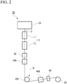
- Example 2 an optical fiber is manufactured by the optical fiber manufacturing apparatus 1B shown in FIG. 2 .
- One ultraviolet irradiation lamp is installed as the first curing unit 40A.
- the second cooling unit 14 one non-contact direction changer 20E (90° conversion) is used.
- Two ultraviolet irradiation lamps are installed as the second curing unit 40B.
- the other configurations are the same as in Example 1.
- the optical fiber is drawn at a drawing speed of 10 m/sec.
- the coating layer of the optical fiber obtained thereby is cured, and the characteristics of the coating layer are also good.
- an optical fiber is manufactured at a drawing speed of 50 m/sec, with the configuration of FIG. 1 excluding the second cooling unit 14.
- the coating layer of the optical fiber obtained thereby way is cured, the Young's modulus of the coating layer is reduced by about 20% as compared with Example 1.
- the optical fiber enters the second curing unit 40B and is cured at a state where the temperature of the semi-cured coating layer is high. That is, since the semi-cured coating layer is cured in a state where the temperature is higher than that in Example 1, the molecular weight of urethane acrylate as the coating layer decreases, and the Young's modulus decreases.
- an optical fiber is manufactured at a drawing speed of 10 m/sec, by changing the non-contact direction changer 20E in the configuration of FIG. 2 to a contact-type direction changer (pulley).
- the cross sectional shape of the coating layer of the optical fiber obtained thereby is deformed and is not a perfect circle. This is because the optical fiber contacts the pulley in a state where the curing of the coating layer is insufficient before passing through the second curing unit 40B.
- the gas sprayed onto the optical fiber by the non-contact direction changers 20A to 20C is air having an oxygen concentration of 20%.
- the optical fiber obtained thereby has insufficient curing of the coating layer and has a sticky surface.
- the urethane acrylate adopted as the coating layer is a radical-curable ultraviolet-curable resin and the oxygen concentration of the sprayed gas is high to cause curing failure due to oxygen inhibition.
- the oxygen concentration of the gas in Example 1 is 10% and the oxygen concentration of the gas in Comparative Example 4 is 20%
- the oxygen concentration of the gas sprayed onto the semi-cured coating layer of the optical fiber by the non-contact direction changers 20A to 20C is preferably 10% or less.
- Example 5 As Comparative Example 5, from the configuration of Example 1, the number of ultraviolet irradiation lamps used as the first curing unit 40A is changed to one.
- the drawing speed is 50 m/sec, which is the same as that of Example 1.
- the cross-sectional shape of the coating layer of the optical fiber obtained thereby is not a perfect circle. This is because as compared with Example 1, as a result of reducing the number of ultraviolet irradiation lamps to be installed as the first curing unit 40A, gases of the non-contact direction changers 20A to 20C are sprayed onto the optical fiber in a state where the curing of the coating layer is insufficient, and the coating layer is deformed.
- the curing degree K of the semi-cured coating layer after passing through the first curing unit 40A is 0.25 in Example 1 and 0.20 in Comparative Example 5. From this, in the first curing step, it is desirable to cure the uncured coating layer until the curing degree K of the semi-cured coating layer becomes 0.25 or more.
- the faster the drawing speed the shorter the time for the optical fiber to pass through one curing device, and the smaller the amount of ultraviolet light absorbed by the uncured coating layer or the semi-cured coating layer. Therefore, the number of curing devices disposed as the first curing unit 40A may be adjusted according to the drawing speed such that the curing degree K of the semi-cured coating layer after passing through the first curing unit 40A is 0.25 or more.
- a second cooling step of cooling the semi-cured coating layer by at least one non-contact direction changer between the first curing step and the second curing step there is a second cooling step of cooling the semi-cured coating layer by at least one non-contact direction changer between the first curing step and the second curing step.
- the semi-cured coating layer is cooled by the non-contact direction changers 20A to 20C, 20E.
- the non-contact direction changers 20A to 20C, 20E have high cooling ability to spray gas onto the optical fiber, and can reliably cool the semi-cured coating layer in a short time. Therefore, the drawing speed can be increased.
- by cooling the semi-cured coating layer while changing the traveling direction of the optical fiber from the up-down direction to the horizontal direction for example, by the non-contact direction changers 20A to 20C, 20E, it is possible to prevent the size of the entire device from increasing in the height direction.
- the pressure of the gas may cause the semi-cured coating layer to be deformed. Therefore, in the first curing step, the uncured coating layer may be cured until the curing degree K of the semi-cured coating layer becomes 0.25 or more. Thus, it is possible to limit the deformation of the coating layer due to the pressure of the gas of the non-contact direction changers 20A to 20C, 20E.
- the non-contact direction changers 20A to 20C, 20E may set the oxygen concentration of the gas sprayed onto the semi-cured coating layer to 10% or less.
- the cooling cylinder is used as the cooler 12 in the optical fiber manufacturing apparatuses 1A, 1B of the embodiment, the cooler 12 having another configuration may be employed.
- the cooler 12 it is also possible to employ a non-contact direction changer as the cooler 12.
- optical fiber manufacturing apparatuses 1A, 1B of the embodiment is equipped with the slow-cooling furnace 11, a configuration not equipped with the slow-cooling furnace 11 may be adopted according to the level of the transmission loss required for the optical fiber.
- optical fiber manufacturing apparatuses 1A, 1B of the embodiment each is equipped with two curing units 40A, 40B, three or more curing units may be provided.
- a non-contact direction changer may be disposed between curing units which are separately positioned in a plurality of places.
Landscapes
- Chemical & Material Sciences (AREA)
- Life Sciences & Earth Sciences (AREA)
- Engineering & Computer Science (AREA)
- Geochemistry & Mineralogy (AREA)
- General Life Sciences & Earth Sciences (AREA)
- Materials Engineering (AREA)
- Organic Chemistry (AREA)
- Chemical Kinetics & Catalysis (AREA)
- General Chemical & Material Sciences (AREA)
- Manufacturing & Machinery (AREA)
- Physics & Mathematics (AREA)
- Thermal Sciences (AREA)
- Optical Fibers, Optical Fiber Cores, And Optical Fiber Bundles (AREA)
- Surface Treatment Of Glass Fibres Or Filaments (AREA)
Abstract
Description
- The present invention relates to an optical fiber manufacturing method.
- Priority is claimed on Japanese Patent Application No.
2017-077688, filed on April 10, 2017 - In the related art, an optical fiber manufacturing method including a drawing step, a coating step, and a curing step has been known. In the drawing step, an optical fiber preform is drawn to form a bare optical fiber. In the coating step, a coating layer which is uncured (hereinafter, simply referred to as an uncured coating layer) made of resin is provided on the outer periphery of the bare optical fiber. In the curing step, the uncured coating layer is cured.
- In such a manufacturing method, in order to increase the production capacity of an optical fiber, it is necessary to increase a drawing speed. However, if the drawing speed is increased, the time for the optical fiber to pass through a cooling device or a coating curing device becomes short, so it is necessary to increase the number of these devices.
- Further, if a high temperature bare optical fiber drawn from a melting furnace is slowly cooled by a slow-cooling furnace, a transmission loss, which is one of the important characteristics of an optical fiber, can be reduced. Therefore, in order to increase the drawing speed while limiting the increase in transmission loss, it is necessary to increase the number of slow-cooling furnaces.
- Here, a bare optical fiber without the coating layer which is easily damaged is provided passes through the slow-cooling furnace. In addition, an optical fiber having a liquid uncured coating layer is passed through the coating curing device. If the optical fiber in these states is brought into contact with a pulley or the like for changing the direction, it may cause the reduction of the strength of the optical fiber, and the deformation of the coating layer. Therefore, each device needs to be located directly below the melting furnace of the optical fiber preform.
- As described above, in order to raise the production capacity of an optical fiber, it is necessary to increase the number of devices disposed directly below a melting furnace. However, in the existing factory building where the space in the height direction is limited, it is difficult to increase the number of devices in this manner, which results in the limitation of drawing speed.
- As a technology for overcoming this limitation, Patent Document 1 discloses a non-contact direction changer. The non-contact direction changer can change the traveling direction of the optical fiber without bringing its components into contact with the optical fiber. By using the non-contact direction changer, it is possible to change the traveling direction of the optical fiber even before the uncured coating layer is formed or the uncured coating layer is completely cured. Thus, each device can be disposed freely, and the drawing speed can be increased even in a place where there is a space limitation in the height direction.
- [Patent Document 1] Japanese Patent No.
5851636 - Meanwhile, as a coating layer of an optical fiber, an ultraviolet-curable resin which can be cured at high speed is generally used. In a case where the ultraviolet-curable resin is used as the coating layer, an ultraviolet lamp, a UV-LED or the like is employed as the coating curing device. Here, it is known that when curing an ultraviolet-curable resin, the temperature at the time of curing of the resin is a factor that determines the degree of curing and the molecular weight of the resin after curing. For example, if the temperature at the time of curing is too high, the curing may be insufficient or the characteristics such as Young's modulus may deteriorate because the molecular weight of the resin after curing is small. In particular, as the drawing speed increases, this problem is more likely to occur because the time spent for cooling the bare optical fiber or the uncured coating layer becomes shorter. Further, in order to stably coat the resin material to be the coating layer on the bare optical fiber, the temperature of the resin material may be increased for the purpose of reducing the viscosity of the resin material. Increasing the temperature of the resin material to adjust the viscosity may also be a factor to increase the temperature of the uncured coating layer. Receiving the heat emitted by an ultraviolet lamp or the like may also be a factor to increase the temperature of the uncured coating layer.
- The present invention has been made in view of such circumstances, and an object of the present invention is to provide a manufacturing method of an optical fiber having a coating layer in a desired state while increasing the drawing speed of the optical fiber.
- In order to solve the above-described problem, an optical fiber manufacturing method according to an aspect of the present invention includes a drawing step of drawing an optical fiber preform to form a bare optical fiber; a first cooling step of cooling the bare optical fiber; a coating step of providing an uncured coating layer containing a resin precursor on an outer periphery of the bare optical fiber; a first curing step of curing the uncured coating layer to form a semi-cured coating layer; a second curing step of further curing the semi-cured coating layer; and a second cooling step of cooling the semi-cured coating layer by at least one non-contact direction changer between the first curing step and the second curing step.
- According to the above aspect of the present invention, it is possible to manufacture an optical fiber having a coating layer in a desired state while increasing the drawing speed of the optical fiber.
-
-
FIG. 1 is a schematic view showing a configuration of an optical fiber manufacturing apparatus according to a first embodiment. -
FIG. 2 is a schematic view showing a configuration of an optical fiber manufacturing apparatus according to a second embodiment. - The configuration of an optical fiber manufacturing apparatus according to the first embodiment will be described below with reference to
FIG. 1 . In each drawing used in the following description, the scale is appropriately changed in order to make each member recognizable. - As shown in
FIG. 1 , the opticalfiber manufacturing apparatus 1A includes adrawing unit 10, afirst cooling unit 13, acoating unit 30, afirst curing unit 40A,non-contact direction changers 20A to 20C, asecond curing unit 40B, an outerdiameter measurement unit 50, adirection changer 20D, and awinder 90, and the respective units are disposed in this order from the top. - The
drawing unit 10 includes a melting furnace or the like for melting an optical fiber preform. Thedrawing unit 10 forms a bareoptical fiber 3. - The
first cooling unit 13 includes a slow-cooling furnace 11 and acooler 12. The slow-cooling furnace 11 is a device for gradually cooling the high temperature bareoptical fiber 3 drawn from the melting furnace of thedrawing unit 10. By slowly cooling the bareoptical fiber 3 by the slow-cooling furnace 11, the transmission loss of the optical fiber can be reduced. As the cooler 12, a cooling cylinder or the like can be employed. The cooling cylinder introduces gas into the cavity of the water-cooled cylinder, and passes the optical fiber through the cavity to cool the optical fiber. The gas introduced into the cavity includes helium, nitrogen, carbon dioxide, or a mixed gas thereof. For example, the heat transfer rates of helium and nitrogen are different. Therefore, in a case of introducing a mixed gas of helium and nitrogen into the cavity, it is possible to adjust the temperature of the bareoptical fiber 3 passing through the cooling cylinder by changing the mixing ratio of these gases. - The
coating unit 30 applies or coats a fluid material (hereinafter, simply referred to as a resin material) containing a resin precursor to the outer periphery of the bareoptical fiber 3 by die coating or the like to form an uncured coating layer. In the present embodiment, the coating layer in the state before passing through thefirst curing unit 40A is referred to as "uncured coating layer", and the coating layer in the state after passing through thefirst curing unit 40A and before passing through thesecond curing unit 40B is referred to as "semi-cured coating layer". Further, in a case where it does not matter whether the coating layer passes through thecuring units - The coating of the resin material is, for example, a two-layer coating. In the two-layer coating, a resin material for a primary coating layer with a low Young's modulus is applied to the inside, and a resin material for a secondary coating layer with a high Young's modulus is applied to the outside. For example, an ultraviolet-curable resin such as a urethane acrylate resin can be used as the coating layer. In addition, the
coating unit 30 may be configured to coat a primary coating layer and a secondary coating layer separately, or to coat a primary coating layer and a secondary coating layer simultaneously. In the present embodiment, an element which is in a state where the coating layer is provided on the outer periphery of the bareoptical fiber 3 is referred to as an optical fiber. - In order to realize a stable coating, the viscosity of the resin material applied to the bare
optical fiber 3 by thecoating unit 30 needs to be low to some extent. The viscosity of the resin material can be reduced by raising the temperature of the resin material. Therefore, the temperature of the resin material to be applied by thecoating unit 30 may be previously raised above room temperature, which may be one of the factors causing the temperature of the uncured coating layer to rise. In particular, as the viscosity of the resin material at room temperature is higher, it is necessary to raise the temperature of the resin material when applied by thecoating unit 30. - In the case where the coating layer is made of an ultraviolet-curable resin, an ultraviolet irradiation lamp, a UV-LED, and a curing device in which these are combined may be used as the
first curing unit 40A. The number of curing devices disposed as thefirst curing unit 40A may be determined, with the curing degree K of the coating layer that has passed these curing devices as an index. In addition, the curing degree K in the present embodiment is defined using the gel fraction to be described later. - The plurality of
non-contact direction changers first curing unit 40A in this order. Thenon-contact direction changers non-contact direction changer 20A changes the traveling direction of the optical fiber by about 90° from the downward direction to the horizontal direction. The number of installed non-contact direction changers, the installation position, the angle of direction change, or the like may be converted as appropriate. - The
non-contact direction changers 20A to 20C have guide grooves for guiding the bareoptical fiber 3 or the optical fiber. In the guide groove, an outlet for fluid (gas) for floating the optical fibers wired along the guide groove is formed. Thenon-contact direction changers 20A to 20C float the optical fiber, without contacting the component with the optical fiber, by spraying gas such as air or helium (He) onto the optical fiber from the outlet. The configuration of the non-contact direction changer in the present embodiment is the same as the configuration described in Japanese Patent No.5851636 - In a case where air is used as the gas sprayed onto the optical fiber, the amount of gas required to float the optical fiber is, for example, about 100 to 200 L/min. The amount of gas is appropriately changed depending on the width of the gas outlet and the like. By adjusting the amount of gas, it is possible to adjust the floating amount of the optical fiber, that is, the passing position of the optical fiber with respect to each component.
- When the passing position of the optical fiber changes significantly, the optical fiber comes in contact with each component, which causes the strength of the optical fiber to be reduced. Further, a UV-LED may be used as a curing device for the
first curing unit 40A or thesecond curing unit 40B. Since the irradiation light of the UV-LED has directivity, the area in which the ultraviolet ray can be irradiated is relatively small. Therefore, in order to irradiate ultraviolet ray to the uncured coating layer or the semi-cured coating layer reliably, it is necessary to control the passing position of the optical fiber more strictly. Therefore, a position sensor (not shown) is disposed below thenon-contact direction changers 20A to 20C, and the position sensor measures the position of the optical fiber. The amount of gas to be sprayed onto the optical fiber by thenon-contact direction changers 20A to 20C is adjusted such that the position of the optical fiber is an appropriate position, based on the measurement result. - In the case where the coating layer is a radical-curable ultraviolet-curable resin which is cured by radical polymerization, if the oxygen concentration of the gas sprayed onto the optical fiber is high, curing failure occurs due to oxygen inhibition. Therefore, the oxygen concentration of the gas sprayed onto the optical fiber by the
non-contact direction changers 20A to 20C needs to be controlled to an appropriate value. For example, in a case where air is used as the gas, the oxygen concentration of the gas can be adjusted by increasing or decreasing the contents of gases other than oxygen, such as nitrogen contained in the air. - However, when a gas is sprayed onto the optical fiber, the coating layer can be cooled by the gas. The
non-contact direction changers 20A to 20C in the present embodiment are disposed between thefirst curing unit 40A and thesecond curing unit 40B, focusing on the cooling capacity. That is, thenon-contact direction changers 20A to 20C constitute thesecond cooling unit 14 that cools the semi-cured coating layer between thefirst curing unit 40A and thesecond curing unit 40B. - Next, an optical fiber manufacturing method using the optical
fiber manufacturing apparatus 1A configured as described above will be described. - First, in the
drawing unit 10, the optical fiber preform is drawn to form a bare optical fiber 3 (drawing step). - Next, in order to keep the transmission loss of the optical fiber low, the bare
optical fiber 3 is gradually cooled in the slow-coolingfurnace 11. Further, the bareoptical fiber 3 is cooled to a predetermined temperature by the cooler 12 (first cooling step). - Next, in the
coating unit 30, an uncured coating layer containing a resin precursor is provided on the outer periphery of the bareoptical fiber 3 to form an optical fiber (coating step). At this time, the temperature of the resin material applied as the uncured coating layer is previously raised above room temperature in order to reduce its viscosity. - Next, in the
first curing unit 40A, the uncured coating layer is cured to become a semi-cured coating layer (first curing step). In addition, the semi-cured coating layer of the optical fiber which passes through thefirst curing unit 40A is further heated up with the heat or the like emitted by a curing device. - Next, between the first curing step and the second curing step, the semi-cured coating layer is cooled while changing the traveling direction of the optical fiber by the
non-contact direction changers 20A to 20C of the second cooling unit 14 (second cooling step). - Next, in the
second curing unit 40B, the semi-cured coating layer is further cured (second curing step). - Next, in the outer
diameter measurement unit 50, the outer diameter of the optical fiber is measured. - Then, the traveling direction of the optical fiber is changed in a substantially horizontal direction by the
direction changer 20D, and the optical fiber is wound by thewinder 90. In addition, since the coating layer of the optical fiber which passed thesecond curing unit 40B has already been cured, direction changers, such as a contact-type pulley, can be used asdirection changer 20D. - Next, a second embodiment according to the present invention will be described, but the basic configuration is the same as that of the first embodiment. Therefore, the same reference numerals are given to similar configurations, the explanation thereof will be omitted, and only differences therefrom will be described.
- The present embodiment is different from the first embodiment in the configuration of the
second cooling unit 14 and the arrangement of thesecond curing unit 40B. - As shown in
FIG. 2 , in the opticalfiber manufacturing apparatus 1B of the present embodiment, thesecond cooling unit 14 is disposed at the lowermost portion of the opticalfiber manufacturing apparatus 1B. Thesecond cooling unit 14 is formed of onenon-contact direction changer 20E. Thenon-contact direction changer 20E changes the traveling direction of the optical fiber by about 90° from the downward direction to the horizontal direction. - According to the present embodiment, the
second cooling unit 14, thesecond curing unit 40B, and the outerdiameter measurement unit 50 are disposed at the lowermost portion of the opticalfiber manufacturing apparatus 1B. Therefore, compared with the first embodiment, the size in the up-down direction of the entire optical fiber manufacturing apparatus can be reduced. - Hereinafter, the optical fiber manufacturing method of the present embodiment will be described in more detail using a specific example.
- As Example 1, an optical fiber is manufactured by the optical
fiber manufacturing apparatus 1A shown inFIG. 1 . With the outer diameter of the bareoptical fiber 3 as 125 µm, and the outer diameter of the optical fiber as 250 µm, two layers of ultraviolet-curable resin (urethane acrylate) are adopted as the coating layer. The drawing speed is 50 m/sec. Two ultraviolet irradiation lamps are installed as thefirst curing unit 40A. As thesecond cooling unit 14, threenon-contact direction changers non-contact direction changers non-contact direction changers 20A to 20C is air whose oxygen concentration is adjusted to 10%. Four ultraviolet irradiation lamps are installed as thesecond curing unit 40B. - The coating layer of the optical fiber obtained thereby is cured, and the characteristics of the coating layer is also good. The curing degree of the semi-cured coating layer after passing through the
first curing unit 40A is K = 0.25. - Here, the definition of the gel fraction and the curing degree K in this example will be described. The gel fraction is calculated by the following method. First, an optical fiber as a sample is input to a Soxhlet extractor, and Soxhlet extraction is performed using methyl ethyl ketone (MEK) as an extraction solvent, under conditions of a temperature of 90 °C and a time of 240 minutes. Thereafter, the sample is dried at a temperature of 60 °C for 240 minutes. The gel fraction is calculated by dividing the dry weight of the insoluble matter after the extraction by the weight of the sample before extraction. In addition, the temperature at the time of extraction may be a temperature higher than or equal to the boiling point of MEK, and may be the temperature and time at which extraction of elution is saturated. In addition, the dry weight may be saturated with respect to the temperature and time of drying.
- The gel fraction increases with the increase of the UV irradiation amount to the coating layer, and saturates at a certain UV irradiation amount. The UV irradiation amount is a value obtained by multiplying the UV illuminance (mW/cm2) from each UV irradiation device by each irradiation time (second). Further, the irradiation time in the optical fiber manufacturing apparatus is defined as a value obtained by dividing the distance (m) which the optical fiber in the UV irradiation device passes by the drawing speed (m/sec). That is, the relationship between the UV irradiation amount and the gel fraction can be obtained by preparing a plurality of samples by changing the drawing speed, the number of UV irradiation devices, or the UV illuminance, and evaluating the gel fraction of each sample.
- Here, the lower limit value of the UV irradiation amount at which the gel fraction saturates is set to W1, and the saturated gel fraction at that time is set to G1. Next, a sample is prepared with a UV irradiation amount (W2) which is 1/10 of W1, and the gel fraction obtained thereby is defined as G2. Further, when the gel fraction of the sample to be evaluated is G3, the curing degree K of the sample to be evaluated is defined by the following Expression (1).

- As Example 2, an optical fiber is manufactured by the optical
fiber manufacturing apparatus 1B shown inFIG. 2 . One ultraviolet irradiation lamp is installed as thefirst curing unit 40A. As thesecond cooling unit 14, onenon-contact direction changer 20E (90° conversion) is used. Two ultraviolet irradiation lamps are installed as thesecond curing unit 40B. The other configurations are the same as in Example 1. In the present example, the optical fiber is drawn at a drawing speed of 10 m/sec. The coating layer of the optical fiber obtained thereby is cured, and the characteristics of the coating layer are also good. - As Comparative Example 1, an optical fiber is manufactured at a drawing speed of 50 m/sec, with the configuration of
FIG. 1 excluding thesecond cooling unit 14. Although the coating layer of the optical fiber obtained thereby way is cured, the Young's modulus of the coating layer is reduced by about 20% as compared with Example 1. This is because in a state where the semi-cured coating layer is kept heated by passing through thefirst curing unit 40A, the optical fiber enters thesecond curing unit 40B and is cured at a state where the temperature of the semi-cured coating layer is high. That is, since the semi-cured coating layer is cured in a state where the temperature is higher than that in Example 1, the molecular weight of urethane acrylate as the coating layer decreases, and the Young's modulus decreases. - As Comparative Example 2, an optical fiber is manufactured at a drawing speed of 10 m/sec, by changing the
non-contact direction changer 20E in the configuration ofFIG. 2 to a contact-type direction changer (pulley). The cross sectional shape of the coating layer of the optical fiber obtained thereby is deformed and is not a perfect circle. This is because the optical fiber contacts the pulley in a state where the curing of the coating layer is insufficient before passing through thesecond curing unit 40B. - As Comparative Example 3, from the configuration of
FIG. 1 , the positions of thenon-contact direction changers 20A to 20C are converted to the position between thecoating unit 30 and thefirst curing unit 40A. In the optical fiber obtained by this configuration, the coating diameter is largely fluctuated in the longitudinal direction. This is because the uncured coating layer is deformed by the pressure of the gas, by spraying the gas from thenon-contact direction changers 20A to 20C onto the optical fiber, in the uncured state of the coating layer. - As Comparative Example 4, in the configuration of Example 1, the gas sprayed onto the optical fiber by the
non-contact direction changers 20A to 20C is air having an oxygen concentration of 20%. The optical fiber obtained thereby has insufficient curing of the coating layer and has a sticky surface. This is because the urethane acrylate adopted as the coating layer is a radical-curable ultraviolet-curable resin and the oxygen concentration of the sprayed gas is high to cause curing failure due to oxygen inhibition. Since the oxygen concentration of the gas in Example 1 is 10% and the oxygen concentration of the gas in Comparative Example 4 is 20%, in the second cooling step, the oxygen concentration of the gas sprayed onto the semi-cured coating layer of the optical fiber by thenon-contact direction changers 20A to 20C is preferably 10% or less. - As Comparative Example 5, from the configuration of Example 1, the number of ultraviolet irradiation lamps used as the
first curing unit 40A is changed to one. The drawing speed is 50 m/sec, which is the same as that of Example 1. The curing degree of the semi-cured coating layer after passing through thefirst curing unit 40A is K = 0.20. The cross-sectional shape of the coating layer of the optical fiber obtained thereby is not a perfect circle. This is because as compared with Example 1, as a result of reducing the number of ultraviolet irradiation lamps to be installed as thefirst curing unit 40A, gases of thenon-contact direction changers 20A to 20C are sprayed onto the optical fiber in a state where the curing of the coating layer is insufficient, and the coating layer is deformed. - The curing degree K of the semi-cured coating layer after passing through the
first curing unit 40A is 0.25 in Example 1 and 0.20 in Comparative Example 5. From this, in the first curing step, it is desirable to cure the uncured coating layer until the curing degree K of the semi-cured coating layer becomes 0.25 or more. The faster the drawing speed, the shorter the time for the optical fiber to pass through one curing device, and the smaller the amount of ultraviolet light absorbed by the uncured coating layer or the semi-cured coating layer. Therefore, the number of curing devices disposed as thefirst curing unit 40A may be adjusted according to the drawing speed such that the curing degree K of the semi-cured coating layer after passing through thefirst curing unit 40A is 0.25 or more. - As Comparative Example 6, from the configuration of Example 1, the positions of the
non-contact direction changers 20A to 20C are converted to the position before thecoating unit 30. That is, thesecond cooling unit 14 is not provided between thefirst curing unit 40A and thesecond curing unit 40B. The drawing speed is 50 m/sec. Although the coating layer of the optical fiber obtained thereby way is cured, the Young's modulus of the coating layer is reduced by about 20% as compared with Example 1. This is because the cooling in the state of the bareoptical fiber 3 is sufficient, but the semi-cured coating layer is heated because the optical fiber passes through thefirst curing unit 40A, and the optical fiber enters thesecond curing unit 40B in that state, so the semi-cured coating layer is cured at a state where the temperature thereof is high. Instead of curing the coating layer at one time by one curing unit, when the curing unit is divided into a plurality of curing units, and a cooling unit is provided between the curing units, it is possible to limit rising the temperature of the coating layer while curing. - As described above, according to the manufacturing method of the present embodiment, there is a second cooling step of cooling the semi-cured coating layer by at least one non-contact direction changer between the first curing step and the second curing step. Thereby, even if the temperature of the semi-cured coating layer rises in the first curing step, the temperature can be lowered in the second cooling step. With this configuration, in the second curing step, the semi-cured coating layer is prevented from being cured while the temperature of the semi-cured coating layer is high, and it is possible to bring the coating layer after curing into a desired state.
- Further, in the second cooling step, the semi-cured coating layer is cooled by the
non-contact direction changers 20A to 20C, 20E. Thenon-contact direction changers 20A to 20C, 20E have high cooling ability to spray gas onto the optical fiber, and can reliably cool the semi-cured coating layer in a short time. Therefore, the drawing speed can be increased. In addition, by cooling the semi-cured coating layer while changing the traveling direction of the optical fiber from the up-down direction to the horizontal direction, for example, by thenon-contact direction changers 20A to 20C, 20E, it is possible to prevent the size of the entire device from increasing in the height direction. In addition, it is possible to limit that the semi-cured coating layer comes in contact with the components of the direction changer and is deformed. - Further, when gas is sprayed onto the semi-cured coating layer having a low curing degree K, in the
non-contact direction changers 20A to 20C, 20E, the pressure of the gas may cause the semi-cured coating layer to be deformed. Therefore, in the first curing step, the uncured coating layer may be cured until the curing degree K of the semi-cured coating layer becomes 0.25 or more. Thus, it is possible to limit the deformation of the coating layer due to the pressure of the gas of thenon-contact direction changers 20A to 20C, 20E. - In the case where the coating layer is a radical-curable ultraviolet-curable resin, if the oxygen concentration of the gas sprayed onto the coating layer is high, curing failure may occur due to oxygen inhibition. Thus, in the second cooling step, the
non-contact direction changers 20A to 20C, 20E may set the oxygen concentration of the gas sprayed onto the semi-cured coating layer to 10% or less. Thereby, even if the coating layer is a radical-curable UV curable resin, it is possible to limit the occurrence of curing failure of the coating layer due to oxygen inhibition. Further, the semi-cured coating layer can be cured more reliably. - It should be noted that the technical scope of the present invention is not limited to the above-described embodiments, and various modifications can be made without departing from the spirit of the present invention.
- For example, although the cooling cylinder is used as the cooler 12 in the optical
fiber manufacturing apparatuses - Further, although the optical
fiber manufacturing apparatuses furnace 11, a configuration not equipped with the slow-coolingfurnace 11 may be adopted according to the level of the transmission loss required for the optical fiber. - Further, although the optical
fiber manufacturing apparatuses units - In addition, without departing from the spirit of the present invention, it is possible to appropriately replace the constituent elements in the above-described embodiment with well-known constituent elements, and the above-described embodiment and modifications may be appropriately combined.
-
- 1A, 1B
- optical fiber manufacturing apparatus
- 3
- bare optical fiber
- 10
- drawing unit
- 13
- first cooling unit
- 20A to 20C, 20E
- non-contact direction changer
- 30
- coating unit
- 40A
- first curing unit
- 40B
- second curing unit
- 50
- outer diameter measurement unit
- 90
- winder
Claims (3)
- An optical fiber manufacturing method comprising:a drawing step of drawing an optical fiber preform to form a bare optical fiber;a first cooling step of cooling the bare optical fiber;a coating step of providing an uncured coating layer containing a resin precursor on an outer periphery of the bare optical fiber;a first curing step of curing the uncured coating layer to form a semi-cured coating layer;a second curing step of further curing the semi-cured coating layer; anda second cooling step of cooling the semi-cured coating layer by at least one non-contact direction changer between the first curing step and the second curing step.
- The optical fiber manufacturing method according to claim 1,
wherein in the first curing step, the uncured coating layer is cured until a curing degree of the semi-cured coating layer becomes 0.25 or more. - The optical fiber manufacturing method according to claim 1 or 2,
wherein in the second cooling step, an oxygen concentration of gas sprayed onto the semi-cured coating layer by the non-contact direction changer is 10% or less.
Applications Claiming Priority (2)
| Application Number | Priority Date | Filing Date | Title |
|---|---|---|---|
| JP2017077688A JP6457579B2 (en) | 2017-04-10 | 2017-04-10 | Optical fiber manufacturing method |
| PCT/JP2018/004471 WO2018189991A1 (en) | 2017-04-10 | 2018-02-08 | Production method for optical fiber |
Publications (3)
| Publication Number | Publication Date |
|---|---|
| EP3611138A1 true EP3611138A1 (en) | 2020-02-19 |
| EP3611138A4 EP3611138A4 (en) | 2021-01-13 |
| EP3611138B1 EP3611138B1 (en) | 2022-06-29 |
Family
ID=63792632
Family Applications (1)
| Application Number | Title | Priority Date | Filing Date |
|---|---|---|---|
| EP18783900.6A Active EP3611138B1 (en) | 2017-04-10 | 2018-02-08 | Manufacturing method of optical fiber |
Country Status (5)
| Country | Link |
|---|---|
| US (1) | US11306025B2 (en) |
| EP (1) | EP3611138B1 (en) |
| JP (1) | JP6457579B2 (en) |
| CN (1) | CN110506032A (en) |
| WO (1) | WO2018189991A1 (en) |
Families Citing this family (3)
| Publication number | Priority date | Publication date | Assignee | Title |
|---|---|---|---|---|
| JP6561106B2 (en) * | 2017-12-06 | 2019-08-14 | 株式会社フジクラ | Manufacturing method and manufacturing apparatus for optical fiber |
| CN109956708A (en) * | 2019-04-15 | 2019-07-02 | 宣汉正原微玻纤有限公司 | A kind of dedicated sound insulation of aviation, heat-protecting glass fibrous composite and preparation method thereof |
| WO2025121332A1 (en) * | 2023-12-04 | 2025-06-12 | 住友電気工業株式会社 | Manufacturing method for optical fiber |
Family Cites Families (17)
| Publication number | Priority date | Publication date | Assignee | Title |
|---|---|---|---|---|
| JPS5851636B2 (en) | 1977-03-03 | 1983-11-17 | 三菱原子力工業株式会社 | Plasma vacuum container tongue protection device |
| EP0854022A1 (en) | 1997-01-15 | 1998-07-22 | Lucent Technologies Inc. | Two stage curing for optical fiber |
| US7322122B2 (en) * | 1997-01-15 | 2008-01-29 | Draka Comteq B.V. | Method and apparatus for curing a fiber having at least two fiber coating curing stages |
| JP4244925B2 (en) | 2002-07-10 | 2009-03-25 | 住友電気工業株式会社 | Optical fiber manufacturing method |
| JPWO2005049516A1 (en) | 2003-11-18 | 2007-06-07 | 株式会社フジクラ | Optical fiber bare wire drawing method, optical fiber strand manufacturing method, optical fiber strand |
| US8528368B2 (en) | 2007-12-19 | 2013-09-10 | Corning Incorporated | Methods and systems for producing a coated optical fibers |
| US7926304B2 (en) * | 2008-02-28 | 2011-04-19 | Corning Incorporated | Methods for measuring the tension of optical fibers during manufacture |
| EP2294027A1 (en) * | 2008-05-29 | 2011-03-16 | Corning Incorporated | Methods and systems for producing thermoplastic coated optical fibers |
| WO2011155570A1 (en) * | 2010-06-11 | 2011-12-15 | 株式会社フジクラ | Method and device for manufacturing fiber-optic strands |
| JP5417406B2 (en) * | 2011-10-12 | 2014-02-12 | 株式会社フジクラ | Manufacturing method of optical fiber |
| JP5831189B2 (en) | 2011-12-09 | 2015-12-09 | 住友電気工業株式会社 | Optical fiber and optical transmission system |
| JP5732586B1 (en) * | 2014-12-26 | 2015-06-10 | 株式会社フジクラ | Manufacturing method and manufacturing apparatus for optical fiber |
| JP5851636B1 (en) * | 2015-02-10 | 2016-02-03 | 株式会社フジクラ | Manufacturing method, control device, and manufacturing apparatus for optical fiber |
| JP6619200B2 (en) | 2015-10-21 | 2019-12-11 | リンテック株式会社 | Release film for ceramic green sheet manufacturing process |
| RU2018116645A (en) * | 2015-11-04 | 2019-12-04 | Сумитомо Электрик Индастриз, Лтд. | METHOD FOR PRODUCING OPTICAL FIBER, DEVICE FOR MANUFACTURE OF OPTICAL FIBER AND OPTICAL FIBER |
| US20170144930A1 (en) * | 2015-11-20 | 2017-05-25 | Corning Incorporated | Optical fiber production system and method for producing coated optical fiber |
| CN106116138A (en) | 2016-05-18 | 2016-11-16 | 中天科技光纤有限公司 | A kind of wire drawing coating processes of minor diameter low-loss bend-insensitive single-mode optical fiber |
-
2017
- 2017-04-10 JP JP2017077688A patent/JP6457579B2/en active Active
-
2018
- 2018-02-08 WO PCT/JP2018/004471 patent/WO2018189991A1/en not_active Ceased
- 2018-02-08 EP EP18783900.6A patent/EP3611138B1/en active Active
- 2018-02-08 US US16/477,696 patent/US11306025B2/en active Active
- 2018-02-08 CN CN201880023117.8A patent/CN110506032A/en active Pending
Also Published As
| Publication number | Publication date |
|---|---|
| US20190359520A1 (en) | 2019-11-28 |
| WO2018189991A1 (en) | 2018-10-18 |
| EP3611138B1 (en) | 2022-06-29 |
| JP2018177574A (en) | 2018-11-15 |
| US11306025B2 (en) | 2022-04-19 |
| EP3611138A4 (en) | 2021-01-13 |
| JP6457579B2 (en) | 2019-01-23 |
| CN110506032A (en) | 2019-11-26 |
Similar Documents
| Publication | Publication Date | Title |
|---|---|---|
| EP2227445B1 (en) | Fiber cure with extended irradiators and non linear path | |
| CN105859120B (en) | Manufacturing method, control device and the manufacturing device of optical fiber wire rod | |
| US8196435B2 (en) | Holey fiber and method of manufacturing the same | |
| EP3611138B1 (en) | Manufacturing method of optical fiber | |
| US4913859A (en) | Methods of curing optical fiber coatings | |
| US8541064B2 (en) | Methods and systems for producing thermoplastic coated optical fibers | |
| JP2702816B2 (en) | Coated optical fiber | |
| EP0646552B1 (en) | Method of curing dual-coated optical fiber | |
| EP0854022A1 (en) | Two stage curing for optical fiber | |
| JP7155075B2 (en) | Optical fiber manufacturing method | |
| JP6457580B2 (en) | Optical fiber manufacturing method |
Legal Events
| Date | Code | Title | Description |
|---|---|---|---|
| STAA | Information on the status of an ep patent application or granted ep patent |
Free format text: STATUS: THE INTERNATIONAL PUBLICATION HAS BEEN MADE |
|
| PUAI | Public reference made under article 153(3) epc to a published international application that has entered the european phase |
Free format text: ORIGINAL CODE: 0009012 |
|
| STAA | Information on the status of an ep patent application or granted ep patent |
Free format text: STATUS: REQUEST FOR EXAMINATION WAS MADE |
|
| 17P | Request for examination filed |
Effective date: 20190626 |
|
| AK | Designated contracting states |
Kind code of ref document: A1 Designated state(s): AL AT BE BG CH CY CZ DE DK EE ES FI FR GB GR HR HU IE IS IT LI LT LU LV MC MK MT NL NO PL PT RO RS SE SI SK SM TR |
|
| AX | Request for extension of the european patent |
Extension state: BA ME |
|
| DAV | Request for validation of the european patent (deleted) | ||
| DAX | Request for extension of the european patent (deleted) | ||
| A4 | Supplementary search report drawn up and despatched |
Effective date: 20201215 |
|
| RIC1 | Information provided on ipc code assigned before grant |
Ipc: C03B 37/035 20060101AFI20201209BHEP Ipc: C03C 25/12 20060101ALI20201209BHEP |
|
| GRAP | Despatch of communication of intention to grant a patent |
Free format text: ORIGINAL CODE: EPIDOSNIGR1 |
|
| STAA | Information on the status of an ep patent application or granted ep patent |
Free format text: STATUS: GRANT OF PATENT IS INTENDED |
|
| INTG | Intention to grant announced |
Effective date: 20220127 |
|
| RIN1 | Information on inventor provided before grant (corrected) |
Inventor name: ISHIDA, ITARU |
|
| GRAS | Grant fee paid |
Free format text: ORIGINAL CODE: EPIDOSNIGR3 |
|
| GRAA | (expected) grant |
Free format text: ORIGINAL CODE: 0009210 |
|
| STAA | Information on the status of an ep patent application or granted ep patent |
Free format text: STATUS: THE PATENT HAS BEEN GRANTED |
|
| AK | Designated contracting states |
Kind code of ref document: B1 Designated state(s): AL AT BE BG CH CY CZ DE DK EE ES FI FR GB GR HR HU IE IS IT LI LT LU LV MC MK MT NL NO PL PT RO RS SE SI SK SM TR |
|
| REG | Reference to a national code |
Ref country code: CH Ref legal event code: EP |
|
| REG | Reference to a national code |
Ref country code: AT Ref legal event code: REF Ref document number: 1501263 Country of ref document: AT Kind code of ref document: T Effective date: 20220715 |
|
| REG | Reference to a national code |
Ref country code: IE Ref legal event code: FG4D |
|
| REG | Reference to a national code |
Ref country code: DE Ref legal event code: R096 Ref document number: 602018037371 Country of ref document: DE |
|
| REG | Reference to a national code |
Ref country code: NL Ref legal event code: FP |
|
| REG | Reference to a national code |
Ref country code: LT Ref legal event code: MG9D |
|
| PG25 | Lapsed in a contracting state [announced via postgrant information from national office to epo] |
Ref country code: SE Free format text: LAPSE BECAUSE OF FAILURE TO SUBMIT A TRANSLATION OF THE DESCRIPTION OR TO PAY THE FEE WITHIN THE PRESCRIBED TIME-LIMIT Effective date: 20220629 Ref country code: NO Free format text: LAPSE BECAUSE OF FAILURE TO SUBMIT A TRANSLATION OF THE DESCRIPTION OR TO PAY THE FEE WITHIN THE PRESCRIBED TIME-LIMIT Effective date: 20220929 Ref country code: LT Free format text: LAPSE BECAUSE OF FAILURE TO SUBMIT A TRANSLATION OF THE DESCRIPTION OR TO PAY THE FEE WITHIN THE PRESCRIBED TIME-LIMIT Effective date: 20220629 Ref country code: HR Free format text: LAPSE BECAUSE OF FAILURE TO SUBMIT A TRANSLATION OF THE DESCRIPTION OR TO PAY THE FEE WITHIN THE PRESCRIBED TIME-LIMIT Effective date: 20220629 Ref country code: GR Free format text: LAPSE BECAUSE OF FAILURE TO SUBMIT A TRANSLATION OF THE DESCRIPTION OR TO PAY THE FEE WITHIN THE PRESCRIBED TIME-LIMIT Effective date: 20220930 Ref country code: FI Free format text: LAPSE BECAUSE OF FAILURE TO SUBMIT A TRANSLATION OF THE DESCRIPTION OR TO PAY THE FEE WITHIN THE PRESCRIBED TIME-LIMIT Effective date: 20220629 Ref country code: BG Free format text: LAPSE BECAUSE OF FAILURE TO SUBMIT A TRANSLATION OF THE DESCRIPTION OR TO PAY THE FEE WITHIN THE PRESCRIBED TIME-LIMIT Effective date: 20220929 |
|
| REG | Reference to a national code |
Ref country code: AT Ref legal event code: MK05 Ref document number: 1501263 Country of ref document: AT Kind code of ref document: T Effective date: 20220629 |
|
| PG25 | Lapsed in a contracting state [announced via postgrant information from national office to epo] |
Ref country code: RS Free format text: LAPSE BECAUSE OF FAILURE TO SUBMIT A TRANSLATION OF THE DESCRIPTION OR TO PAY THE FEE WITHIN THE PRESCRIBED TIME-LIMIT Effective date: 20220629 Ref country code: LV Free format text: LAPSE BECAUSE OF FAILURE TO SUBMIT A TRANSLATION OF THE DESCRIPTION OR TO PAY THE FEE WITHIN THE PRESCRIBED TIME-LIMIT Effective date: 20220629 |
|
| PG25 | Lapsed in a contracting state [announced via postgrant information from national office to epo] |
Ref country code: SM Free format text: LAPSE BECAUSE OF FAILURE TO SUBMIT A TRANSLATION OF THE DESCRIPTION OR TO PAY THE FEE WITHIN THE PRESCRIBED TIME-LIMIT Effective date: 20220629 Ref country code: SK Free format text: LAPSE BECAUSE OF FAILURE TO SUBMIT A TRANSLATION OF THE DESCRIPTION OR TO PAY THE FEE WITHIN THE PRESCRIBED TIME-LIMIT Effective date: 20220629 Ref country code: RO Free format text: LAPSE BECAUSE OF FAILURE TO SUBMIT A TRANSLATION OF THE DESCRIPTION OR TO PAY THE FEE WITHIN THE PRESCRIBED TIME-LIMIT Effective date: 20220629 Ref country code: PT Free format text: LAPSE BECAUSE OF FAILURE TO SUBMIT A TRANSLATION OF THE DESCRIPTION OR TO PAY THE FEE WITHIN THE PRESCRIBED TIME-LIMIT Effective date: 20221031 Ref country code: ES Free format text: LAPSE BECAUSE OF FAILURE TO SUBMIT A TRANSLATION OF THE DESCRIPTION OR TO PAY THE FEE WITHIN THE PRESCRIBED TIME-LIMIT Effective date: 20220629 Ref country code: EE Free format text: LAPSE BECAUSE OF FAILURE TO SUBMIT A TRANSLATION OF THE DESCRIPTION OR TO PAY THE FEE WITHIN THE PRESCRIBED TIME-LIMIT Effective date: 20220629 Ref country code: AT Free format text: LAPSE BECAUSE OF FAILURE TO SUBMIT A TRANSLATION OF THE DESCRIPTION OR TO PAY THE FEE WITHIN THE PRESCRIBED TIME-LIMIT Effective date: 20220629 |
|
| PG25 | Lapsed in a contracting state [announced via postgrant information from national office to epo] |
Ref country code: PL Free format text: LAPSE BECAUSE OF FAILURE TO SUBMIT A TRANSLATION OF THE DESCRIPTION OR TO PAY THE FEE WITHIN THE PRESCRIBED TIME-LIMIT Effective date: 20220629 Ref country code: IS Free format text: LAPSE BECAUSE OF FAILURE TO SUBMIT A TRANSLATION OF THE DESCRIPTION OR TO PAY THE FEE WITHIN THE PRESCRIBED TIME-LIMIT Effective date: 20221029 |
|
| REG | Reference to a national code |
Ref country code: DE Ref legal event code: R097 Ref document number: 602018037371 Country of ref document: DE |
|
| PG25 | Lapsed in a contracting state [announced via postgrant information from national office to epo] |
Ref country code: AL Free format text: LAPSE BECAUSE OF FAILURE TO SUBMIT A TRANSLATION OF THE DESCRIPTION OR TO PAY THE FEE WITHIN THE PRESCRIBED TIME-LIMIT Effective date: 20220629 |
|
| PG25 | Lapsed in a contracting state [announced via postgrant information from national office to epo] |
Ref country code: DK Free format text: LAPSE BECAUSE OF FAILURE TO SUBMIT A TRANSLATION OF THE DESCRIPTION OR TO PAY THE FEE WITHIN THE PRESCRIBED TIME-LIMIT Effective date: 20220629 Ref country code: CZ Free format text: LAPSE BECAUSE OF FAILURE TO SUBMIT A TRANSLATION OF THE DESCRIPTION OR TO PAY THE FEE WITHIN THE PRESCRIBED TIME-LIMIT Effective date: 20220629 |
|
| PLBE | No opposition filed within time limit |
Free format text: ORIGINAL CODE: 0009261 |
|
| STAA | Information on the status of an ep patent application or granted ep patent |
Free format text: STATUS: NO OPPOSITION FILED WITHIN TIME LIMIT |
|
| 26N | No opposition filed |
Effective date: 20230330 |
|
| P01 | Opt-out of the competence of the unified patent court (upc) registered |
Effective date: 20230512 |
|
| PG25 | Lapsed in a contracting state [announced via postgrant information from national office to epo] |
Ref country code: SI Free format text: LAPSE BECAUSE OF FAILURE TO SUBMIT A TRANSLATION OF THE DESCRIPTION OR TO PAY THE FEE WITHIN THE PRESCRIBED TIME-LIMIT Effective date: 20220629 |
|
| REG | Reference to a national code |
Ref country code: DE Ref legal event code: R119 Ref document number: 602018037371 Country of ref document: DE |
|
| PG25 | Lapsed in a contracting state [announced via postgrant information from national office to epo] |
Ref country code: MC Free format text: LAPSE BECAUSE OF FAILURE TO SUBMIT A TRANSLATION OF THE DESCRIPTION OR TO PAY THE FEE WITHIN THE PRESCRIBED TIME-LIMIT Effective date: 20220629 |
|
| REG | Reference to a national code |
Ref country code: CH Ref legal event code: PL |
|
| REG | Reference to a national code |
Ref country code: BE Ref legal event code: MM Effective date: 20230228 |
|
| GBPC | Gb: european patent ceased through non-payment of renewal fee |
Effective date: 20230208 |
|
| PG25 | Lapsed in a contracting state [announced via postgrant information from national office to epo] |
Ref country code: LU Free format text: LAPSE BECAUSE OF NON-PAYMENT OF DUE FEES Effective date: 20230208 Ref country code: LI Free format text: LAPSE BECAUSE OF NON-PAYMENT OF DUE FEES Effective date: 20230228 Ref country code: CH Free format text: LAPSE BECAUSE OF NON-PAYMENT OF DUE FEES Effective date: 20230228 |
|
| REG | Reference to a national code |
Ref country code: IE Ref legal event code: MM4A |
|
| PG25 | Lapsed in a contracting state [announced via postgrant information from national office to epo] |
Ref country code: GB Free format text: LAPSE BECAUSE OF NON-PAYMENT OF DUE FEES Effective date: 20230208 |
|
| PG25 | Lapsed in a contracting state [announced via postgrant information from national office to epo] |
Ref country code: IE Free format text: LAPSE BECAUSE OF NON-PAYMENT OF DUE FEES Effective date: 20230208 Ref country code: GB Free format text: LAPSE BECAUSE OF NON-PAYMENT OF DUE FEES Effective date: 20230208 Ref country code: DE Free format text: LAPSE BECAUSE OF NON-PAYMENT OF DUE FEES Effective date: 20230901 |
|
| PG25 | Lapsed in a contracting state [announced via postgrant information from national office to epo] |
Ref country code: BE Free format text: LAPSE BECAUSE OF NON-PAYMENT OF DUE FEES Effective date: 20230228 |
|
| PG25 | Lapsed in a contracting state [announced via postgrant information from national office to epo] |
Ref country code: BG Free format text: LAPSE BECAUSE OF FAILURE TO SUBMIT A TRANSLATION OF THE DESCRIPTION OR TO PAY THE FEE WITHIN THE PRESCRIBED TIME-LIMIT Effective date: 20220629 |
|
| PG25 | Lapsed in a contracting state [announced via postgrant information from national office to epo] |
Ref country code: BG Free format text: LAPSE BECAUSE OF FAILURE TO SUBMIT A TRANSLATION OF THE DESCRIPTION OR TO PAY THE FEE WITHIN THE PRESCRIBED TIME-LIMIT Effective date: 20220629 |
|
| PG25 | Lapsed in a contracting state [announced via postgrant information from national office to epo] |
Ref country code: CY Free format text: LAPSE BECAUSE OF FAILURE TO SUBMIT A TRANSLATION OF THE DESCRIPTION OR TO PAY THE FEE WITHIN THE PRESCRIBED TIME-LIMIT; INVALID AB INITIO Effective date: 20180208 |
|
| PG25 | Lapsed in a contracting state [announced via postgrant information from national office to epo] |
Ref country code: HU Free format text: LAPSE BECAUSE OF FAILURE TO SUBMIT A TRANSLATION OF THE DESCRIPTION OR TO PAY THE FEE WITHIN THE PRESCRIBED TIME-LIMIT; INVALID AB INITIO Effective date: 20180208 |
|
| PG25 | Lapsed in a contracting state [announced via postgrant information from national office to epo] |
Ref country code: TR Free format text: LAPSE BECAUSE OF FAILURE TO SUBMIT A TRANSLATION OF THE DESCRIPTION OR TO PAY THE FEE WITHIN THE PRESCRIBED TIME-LIMIT Effective date: 20220629 |
|
| PGFP | Annual fee paid to national office [announced via postgrant information from national office to epo] |
Ref country code: FR Payment date: 20251231 Year of fee payment: 9 |
|
| PGFP | Annual fee paid to national office [announced via postgrant information from national office to epo] |
Ref country code: NL Payment date: 20260106 Year of fee payment: 9 |
|
| PGFP | Annual fee paid to national office [announced via postgrant information from national office to epo] |
Ref country code: IT Payment date: 20260122 Year of fee payment: 9 |