EP3611048B1 - Clutching lamp adjuster - Google Patents
Clutching lamp adjuster Download PDFInfo
- Publication number
- EP3611048B1 EP3611048B1 EP19185561.8A EP19185561A EP3611048B1 EP 3611048 B1 EP3611048 B1 EP 3611048B1 EP 19185561 A EP19185561 A EP 19185561A EP 3611048 B1 EP3611048 B1 EP 3611048B1
- Authority
- EP
- European Patent Office
- Prior art keywords
- retainer
- lamp
- adjuster
- base screw
- mating portion
- Prior art date
- Legal status (The legal status is an assumption and is not a legal conclusion. Google has not performed a legal analysis and makes no representation as to the accuracy of the status listed.)
- Active
Links
Images











Classifications
-
- B—PERFORMING OPERATIONS; TRANSPORTING
- B60—VEHICLES IN GENERAL
- B60Q—ARRANGEMENT OF SIGNALLING OR LIGHTING DEVICES, THE MOUNTING OR SUPPORTING THEREOF OR CIRCUITS THEREFOR, FOR VEHICLES IN GENERAL
- B60Q1/00—Arrangement of optical signalling or lighting devices, the mounting or supporting thereof or circuits therefor
- B60Q1/02—Arrangement of optical signalling or lighting devices, the mounting or supporting thereof or circuits therefor the devices being primarily intended to illuminate the way ahead or to illuminate other areas of way or environments
- B60Q1/04—Arrangement of optical signalling or lighting devices, the mounting or supporting thereof or circuits therefor the devices being primarily intended to illuminate the way ahead or to illuminate other areas of way or environments the devices being headlights
- B60Q1/06—Arrangement of optical signalling or lighting devices, the mounting or supporting thereof or circuits therefor the devices being primarily intended to illuminate the way ahead or to illuminate other areas of way or environments the devices being headlights adjustable, e.g. remotely-controlled from inside vehicle
- B60Q1/068—Arrangement of optical signalling or lighting devices, the mounting or supporting thereof or circuits therefor the devices being primarily intended to illuminate the way ahead or to illuminate other areas of way or environments the devices being headlights adjustable, e.g. remotely-controlled from inside vehicle by mechanical means
- B60Q1/0683—Adjustable by rotation of a screw
-
- B—PERFORMING OPERATIONS; TRANSPORTING
- B60—VEHICLES IN GENERAL
- B60Q—ARRANGEMENT OF SIGNALLING OR LIGHTING DEVICES, THE MOUNTING OR SUPPORTING THEREOF OR CIRCUITS THEREFOR, FOR VEHICLES IN GENERAL
- B60Q1/00—Arrangement of optical signalling or lighting devices, the mounting or supporting thereof or circuits therefor
- B60Q1/02—Arrangement of optical signalling or lighting devices, the mounting or supporting thereof or circuits therefor the devices being primarily intended to illuminate the way ahead or to illuminate other areas of way or environments
- B60Q1/04—Arrangement of optical signalling or lighting devices, the mounting or supporting thereof or circuits therefor the devices being primarily intended to illuminate the way ahead or to illuminate other areas of way or environments the devices being headlights
- B60Q1/06—Arrangement of optical signalling or lighting devices, the mounting or supporting thereof or circuits therefor the devices being primarily intended to illuminate the way ahead or to illuminate other areas of way or environments the devices being headlights adjustable, e.g. remotely-controlled from inside vehicle
- B60Q1/076—Arrangement of optical signalling or lighting devices, the mounting or supporting thereof or circuits therefor the devices being primarily intended to illuminate the way ahead or to illuminate other areas of way or environments the devices being headlights adjustable, e.g. remotely-controlled from inside vehicle by electrical means including means to transmit the movements, e.g. shafts or joints
-
- B—PERFORMING OPERATIONS; TRANSPORTING
- B60—VEHICLES IN GENERAL
- B60Q—ARRANGEMENT OF SIGNALLING OR LIGHTING DEVICES, THE MOUNTING OR SUPPORTING THEREOF OR CIRCUITS THEREFOR, FOR VEHICLES IN GENERAL
- B60Q1/00—Arrangement of optical signalling or lighting devices, the mounting or supporting thereof or circuits therefor
- B60Q1/02—Arrangement of optical signalling or lighting devices, the mounting or supporting thereof or circuits therefor the devices being primarily intended to illuminate the way ahead or to illuminate other areas of way or environments
- B60Q1/04—Arrangement of optical signalling or lighting devices, the mounting or supporting thereof or circuits therefor the devices being primarily intended to illuminate the way ahead or to illuminate other areas of way or environments the devices being headlights
- B60Q1/18—Arrangement of optical signalling or lighting devices, the mounting or supporting thereof or circuits therefor the devices being primarily intended to illuminate the way ahead or to illuminate other areas of way or environments the devices being headlights being additional front lights
- B60Q1/20—Fog lights
-
- F—MECHANICAL ENGINEERING; LIGHTING; HEATING; WEAPONS; BLASTING
- F16—ENGINEERING ELEMENTS AND UNITS; GENERAL MEASURES FOR PRODUCING AND MAINTAINING EFFECTIVE FUNCTIONING OF MACHINES OR INSTALLATIONS; THERMAL INSULATION IN GENERAL
- F16H—GEARING
- F16H25/00—Gearings comprising primarily only cams, cam-followers and screw-and-nut mechanisms
- F16H25/18—Gearings comprising primarily only cams, cam-followers and screw-and-nut mechanisms for conveying or interconverting oscillating or reciprocating motions
- F16H25/20—Screw mechanisms
-
- F—MECHANICAL ENGINEERING; LIGHTING; HEATING; WEAPONS; BLASTING
- F16—ENGINEERING ELEMENTS AND UNITS; GENERAL MEASURES FOR PRODUCING AND MAINTAINING EFFECTIVE FUNCTIONING OF MACHINES OR INSTALLATIONS; THERMAL INSULATION IN GENERAL
- F16H—GEARING
- F16H35/00—Gearings or mechanisms with other special functional features
- F16H35/18—Turning devices for rotatable members, e.g. shafts
Definitions
- the present invention relates generally to the field of adjusters. More particularly, the present invention relates to an adjuster for fog lamps, headlamps, and other forms of adjustable automotive lamps that allows clutching throughout travel.
- WO2009/076438A1 describes a headlamp assembly including an adjusting mechanism for adjusting the aim of a headlamp.
- the mechanism includes a gear screw that is snap fit into the headlamp housing, a grommet positioned around the gear screw and snap fit into the headlamp reflector, and an O-ring.
- GB2285307A describes a vehicular headlamp comprising a stationary member, a tiltable member pivotally movable relatively to the stationary member for varying the direction of the light transmission, an adjusting shaft rotatably supported by the stationary member and having a screw threaded portion which engages a nut connected to the tiltable member, whereby rotation of the shaft relatively to the nut causes the tiltable member to pivot, the nut being resilient and having an axially extending notch in its side wall through which the screw threaded portion of the shaft can be forced to engage the shaft with the nut during assembly.
- US5678915A describes a reflector with an electric lighting bulb mounted thereto coupled to a lamp body via a ball-and-socket connection and a vertical and a horizontal aiming screw.
- Each aiming screw comprises a threaded shank engaged with a nut on the back of the reflector, a journal joined to the threaded shank and rotatably received in a bearing sleeve formed on the lamp body, and a head portion joined to the journal and projecting rearwardly from the bearing sleeve.
- the aiming screw is formed to include two collars for engaging the bearing sleeve therebetween and so the aiming screw is restrained from axial displacement relative to the sleeve.
- the diameters of the various parts of the aiming screw and of the bearing sleeve are so determined in relation to one another that, in the assemblage of the headlamp, the aiming screw can be inserted, with its head portion foremost, into and through the bearing sleeve from inside the lamp body, either before or after coupling the aiming screw to the reflector via the nut.
- US2013/141930A1 describes a vehicular headlamp including a lamp body that has a cylindrical portion having a front opening and a rear opening; a translucent cover that covers the front opening, a metallic light source base that has a light source installation portion, which is inserted from the rear opening to the lamp body and disposed therein, an annular elastic body coupling the lamp body to the light source base and closing a clearance between the lamp body and the light source base, and an optical axis adjustment mechanism coupling the lamp body to the light source base, wherein the light source base is supported so as to be turnable with respect to the lamp body by operation of the optical axis adjustment mechanism, and the elastic body is configured to be elastically deformed as the light source base is turned with respect to the lamp body.
- JPH08115064A describes an adjustment nut inserted from a clip board to a nut fixing hole to be fixed to the hole.
- a blade part of the board is bent in such a state as narrowing its angle of approximately V shape, passed the hole, and when it reaches a rear face it is enlarged by elasticity.
- the upper plane of a block body projecting face and the upper plane of the wing part projecting face are contacted with a surface and the rear face of the hole respectively so as to sandwich the board thickness with performing engagement.
- a size different in the board thickness is absorbed by deflection of the blade part and the nut is in an erecting state to the hole so that it can be held at a right position for threaded engagement with an adjustment screw, which is performed afterward.
- the present invention provides an adjuster for adjusting automotive lamps.
- such adjuster includes a retainer and a base screw configured in a manner that permits clutching throughout travel.
- the present invention provides an adjuster for adjustable automotive lamps.
- the adjuster comprises a base screw and a retainer.
- the base screw includes a threaded shaft.
- the retainer connects to the threaded shaft and includes a semicircular sidewall, a plurality of retainer snap fingers, and a plurality of retainer spring fingers.
- the semicircular sidewall includes interior threads that correlate to the threads of the threaded shaft.
- the semicircular sidewall further surrounds at least a portion of the threaded shaft and defines a clutching opening.
- the clutching opening permits expansion of the semicircular sidewall when the threaded shaft slips with respect to the interior threads.
- the retainer snap fingers are located proximate to a distal end of the retainer and are configured to mate to a lamp mating portion of the adjustable automotive lamp.
- the retainer spring fingers are positioned within such proximity to the retainer snap fingers as to further secure the lamp mating portion against substantial sliding movement along the adjuster after the retainer snap fingers mate with the lamp mating portion.
- the retainer snap fingers and the retainer spring fingers flex relative to the semicircular sidewall.
- the invention provides an adjuster assembly for adjustable automotive lamps.
- the adjuster assembly comprises a housing mating portion connected to a lamp housing, a lamp mating portion forming part of the adjustable automotive lamp, and a lamp adjuster connected to both the housing mating portion and the lamp mating portion.
- the lamp adjuster comprises a base screw and a retainer.
- the base screw includes a threaded shaft.
- the retainer connects to the threaded shaft and includes a semicircular sidewall, a plurality of retainer snap fingers, and a plurality of retainer spring fingers.
- the semicircular sidewall includes interior threads that correlate to the threads of the threaded shaft.
- the semicircular sidewall further surrounds at least a portion of the threaded shaft and defines a clutching opening.
- the clutching opening permits expansion of the semicircular sidewall when the threaded shaft slips with respect to the interior threads.
- the retainer snap fingers are located proximate to a distal end of the retainer and are configured to mate to a lamp mating portion of the adjustable automotive lamp.
- the retainer spring fingers are positioned within such proximity to the retainer snap fingers as to further secure the lamp mating portion against substantial sliding movement along the adjuster after the retainer snap fingers mate with the lamp mating portion.
- the retainer snap fingers and the retainer spring fingers flex relative to the semicircular sidewall.
- the invention provides the adjuster with a base screw comprising a plurality of base screw snap fingers configured to mate to a housing mating portion of a lamp housing in a manner that permits rotation of the base screw with respect the housing mating portion.
- the base screw also has a securement mechanism configured to secure the housing mating portion against substantial longitudinal movement after the plurality of base screw snap fingers mates with the housing mating portion and an orientation tab located on a distal end of the base screw.
- the orientation tab is configured to signal proper orientation of the adjuster to a user installing the adjuster.
- the plurality of retainer snap fingers and the plurality of retainer spring fingers comprise a pair of opposing retainer snap fingers, respectively a pair of opposing retainer spring fingers.
- the pair of retainer snap fingers are configured to mate to a lamp mating portion of an automotive lamp heat sink in a manner that fixes the retainer against rotation.
- fog lamp can be applied equally well to other adjustable lamps, such as headlamps. References to fog lamps hereinafter should not be read as limiting the device for use solely with fog lamps.
- FIG. 1 shows one embodiment of a clutching fog lamp adjuster assembly 10.
- the adjuster assembly 10 includes a clutching fog lamp adjuster 12, a housing mating portion 14, and a lamp mating panel 16.
- the housing mating portion 14 may form a portion of a broader lamp housing
- the lamp mating panel 16 may form a portion of a broader lamp heat sink (not shown), but for convenience and clarity, the remainder of the housing and of the lamp heat sink are omitted from the drawings of this embodiment.
- the adjuster 12 includes a base screw 20, a retainer 18 that screws or snaps onto the base screw 20, and an O-Ring 22 that wraps around a portion of the base screw 20 (see FIG. 2 ).
- the adjuster 12 mates with the housing mating portion 14 at a housing mating end, and with the lamp mating panel 16 at an opposing, retainer mating end.
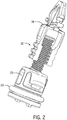
- FIG. 2 shows the adjuster 12 in greater detail. With the housing mating portion 14 and the lamp mating panel 16 removed, the O-Ring 22 is now visible.
- FIGS. 3-6 show one manner of assembling the adjuster assembly 10.
- FIG. 3 is an exploded view of the adjuster 12.
- the base screw 20 includes an O-Ring channel 23 near the housing mating end of the adjuster 12.
- the O-Ring channel 23 allows for proper positioning of the O-Ring 22 and aids in maintain the position of the O-Ring 22 at the housing mating end of the base screw 20.
- FIG. 4 shows the adjuster 12 fully assembled before being mated with the housing mating portion 14.
- the O-Ring 22 is positioned in the O-Ring channel 23, and the retainer 18 is snapped onto the base screw 20.
- a ridged sidewall 15 defines an opening in the housing mating portion 14, sized to permit the adjuster 12 to pass through the opening, beginning at the retainer mating end, until the opposing housing mating end is reached.
- the base screw 20 snaps into place against the ridged sidewall 15, such that the base screw 20 may no longer move in a forward or a rearward direction through the housing mating portion 14, but may still rotate within the opening defined by the ridged sidewall 15.
- the ridged sidewall 15, in this embodiment forms a substantially circular shape
- the ridged sidewall in other embodiments may form other shapes, corresponding to other mating ends of other base screws.
- FIG. 5 shows the adjuster 12 mated with the housing mating portion 14, separated from the lamp mating panel 16. When fully assembled, the lamp mating panel 16 snaps into place at the retainer mating end of the adjuster 12.
- FIGS. 6-8 show top views of various elements of the adjuster assembly 10.
- FIG. 6 shows the adjuster 12 mated with the housing mating portion 14.
- the lamp mating panel 16 is not shown.
- FIG. 7 shows the complete adjuster assembly 10.
- FIG. 8 shows only the lamp mating panel 16.
- the mating geometry 24 is formed in the shape of a plus symbol. In other embodiments, the mating geometry may form other shapes, corresponding to other mating ends of other adjusters.
- FIGS. 9-10 respectively show bottom views of the adjuster assembly 10 and of the housing mating portion 14, alone.
- a distal end of the base screw 20 includes a combination hexagonal-cross recessed interface 25, which allows for multiple component installation and adjustment options.
- the distal end of the base screw 20 may include different forms of interfaces.
- the distal end of the base screw 20 additionally includes orientation tabs 26.
- the orientation tabs 26 allow an assembler to correctly orient the adjuster 12, even when the assembler cannot see beyond the housing mating portion 14, for instance, during a blind assembly.
- the embodiment shown in FIG. 9 includes two orientation tabs 26, and proper installation is signaled by a horizontal orientation of the orientation tabs 26.
- FIG. 10 shows the ridged sidewall 15 extending continuously around the opening formed in housing mating portion 14. The continuity of the ridged sidewall 15 may permit rotation of the base screw 20 within the housing mating portion 14.
- FIG. 11 shows the base screw 20 in greater detail.
- the base screw 20 may include base screw snap fingers 30 that snap into the ridged sidewall 15, contributing to a resilient, but rotatable mating connection with the housing mating portion 14.
- the base screw 20 may additionally include a threaded section 28, to which the retainer 18 connects.
- FIGS. 12-13 show the retainer 18 in greater detail.
- the retainer 18 includes a semicircular retainer sidewall 40.
- the retainer sidewall 40 defines a clutching opening 42.
- a portion of the retainer sidewall 40 may be threaded to form a retainer interface section 38, where the retainer 18 may interact with the threaded section 28 of the base screw 20.
- the unique composition of the retainer sidewall 40 allows for clutching at any point throughout travel.
- the retainer sidewall 40 expands, widening the clutching opening 42 to an extent sufficient to permit slippage of the base screw 20 along the base screw interface 38 without significant damage to the threads of the threaded section 28 until the threaded section 28 once again fits properly within the retainer interface section 38, but not so far as to permit the threaded section 28 to dislodge from the retainer interface section 38.
- Integrated full-travel clutching provides a more robust adjustment solution for systems having increased weight and/or temperatures.
- the retainer 18 additionally includes retainer snap fingers 32 to engage the lamp mating panel 16 and retainer spring fingers 34 to secure the connection to the lamp mating panel 16.
- retainer snap fingers 32 there are two retainer snap fingers 32 and two retainer spring fingers 34, each retainer spring finger 34 located directly below a respective retainer snap finger 32. In other embodiments, there may be a greater number of retainer snap fingers 32 and/or retainer spring fingers 34. Direct engagement of the retainer 18 with the lamp mating panel 16 eliminates the need for installation of a secondary mating socket, simplifying assembly and reducing component count.
- both the retainer snap fingers 32 and the retainer spring fingers 34 are made of an elastic material. Securing the lamp mating panel 16 between multiple, elastic elements, versus a single element or small number of rigid elements, allows the adjuster assembly 10 both to withstand greater system vibrations with decreased likelihood of damage or dislodging, and to accommodate lamp mating panels, or equivalent lamp mating elements, of various thicknesses without requiring higher installation forces or creating a loose joint.
- a travel restriction lug 36 may be attached to the retainer sidewall 40 directly below each retainer spring finger 34. The travel restriction lug 36 limits the distance that the corresponding retainer spring finger 34 may be stretched during installation and general usage, reducing the risk of permanent spring finger deformation.
- FIGS. 14-18 show the various components of the full adjuster assembly 10 interacting with one another.
- the cutaway view in FIG. 15 shows the O-Ring 22 in place between the base screw 20 and the ridged sidewall 15, as well as showing the lamp mating panel 16 locked in place by the retainer snap fingers 32 and further secured by the retainer spring finger 34, also shown in the cross-sectional view in FIG. 18 .
- the custom fit of the retainer mating end within the mating geometry 24 helps control insertion location, promoting proper retainer 18 orientation, and aids in limiting unwanted vibration.
- FIGS. 19-22 illustrate how the lamp mating panel 16 tilts as the retainer 18 is retracted (as shown in FIGS. 19-20 ) or extended (as shown in FIGS. 21-22 ). Notice that the retainer 18 does not rotate as it extends or retracts, but rather, maintains a substantially constant orientation, with the clutching opening 42 facing outwards. This orientation ensures that general usage loads will occur on the retainer sidewall 40, rather than on or opposite the clutching opening 42, which helps prevent dislodging.
- the mating geometry 24 of the lamp mating panel 16 ensures this constant orientation, preventing substantial twisting of the retainer 18.
- the retainer 18 is caused to extend or retract by the interaction between the threaded section 28 of the base screw 20 and the retainer interface section 38 of the retainer 18 as the base screw 20 rotates.
- the rotational energy translates through the rotationally fixed retainer 18 to the lamp mating panel 16, causing the lamp mating panel 16 to pivot.
- the retainer 18 when the retainer 18 is in a retracted position (as shown in FIGS. 19-20 ), the lamp mating panel 16 is tilted in a forward direction, whereas when the retainer 18 is in an extended position (as shown in FIGS. 21-22 ), the lamp mating panel 16 is tilted in a rearward direction.
- FIGS. 23-24 show a clutching fog lamp adjuster assembly 110 according to a second embodiment of the present invention, with expanded views of a lamp housing 104 and a lamp heat sink 106 shown.
- a housing mating portion 114 is attached to the housing 104, and a lamp mating portion 116 is attached to the lamp heat sink 106.
- the housing mating portion 114 is formed as a part of the housing 104 and the lamp mating panel 116 is formed as a part of the lamp heat sink 106, although other means of attachment could be implemented.
- the lamp mating panel 116 is shown in this embodiment to resemble a flat panel, in other embodiments, the mating portion of the lamp heat sink may take on other shapes.
- the clutching lamp adjuster 112 connects to both the housing 104, at the housing mating portion 114, and to the lamp heat sink 106, at the lamp mating panel 116.
- FIG. 25 shows the clutching lamp adjuster assembly 110 including the clutching lamp adjuster 112, the housing mating portion 114, and the lamp mating panel 116.
- the adjuster 112 mates with the housing mating portion 114 at a housing mating end, and with the lamp mating panel 116 at an opposing, retainer mating end.
- FIG. 26 shows the adjuster 112 in greater detail, with the housing mating portion 114 and the lamp mating panel 116 removed.
- the adjuster 112 includes a base screw 120 and a retainer 118 that screws or snaps onto the base screw 120.
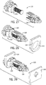
- FIGS. 27-29 show one manner of assembling the adjuster assembly 110.
- FIG. 27 is an exploded view of the adjuster 112.
- FIG. 28 shows the adjuster 112 fully assembled, with the retainer 118 snapped onto the base screw 120, before being mated with the housing mating portion 114.
- a sidewall 115 defines an opening in the housing mating portion 114, sized to permit the adjuster 112 to pass through the opening, beginning at the retainer mating end, until the opposing housing mating end is reached.
- the base screw 120 snaps into place against the sidewall 115, such that the base screw 120 may no longer move in a forward or a rearward direction through the housing mating portion 114, but may still rotate within the opening defined by the sidewall 115.
- the sidewall 115 in this embodiment, forms a substantially circular shape, the sidewall in other embodiments may form other shapes, corresponding to other mating ends of other base screws.
- the present embodiment depicts an adjuster assembly 110 in which no seal is required between the housing mating portion 114 and the base screw 120. Therefore, an O-ring is not included in this embodiment. However, should a seal be desired between the housing mating portion 114 and the base screw 120, an O-ring, for instance an O-ring similar to the O-Ring 22 shown and described in the previous embodiment, may be included in this embodiment.
- FIG. 29 shows the adjuster 112 mated with the housing mating portion 114, but separated from the lamp mating panel 116. When fully assembled, the lamp mating panel 116 snaps into place at the retainer mating end of the adjuster 112.
- FIGS. 30-32 show top views of various elements of the adjuster assembly 110.
- FIG. 30 shows the adjuster 112 mated with the housing mating portion 114.
- the lamp mating panel 116 is not shown.
- FIG. 31 shows the complete adjuster assembly 110.
- FIG. 32 shows only the lamp mating panel 116.
- the mating geometry 124 is formed in the shape of a plus symbol. In other embodiments, the mating geometry may form other shapes, corresponding to other mating ends of other adjusters.
- FIGS. 33-34 respectively show bottom views of the adjuster assembly 110 and of the housing mating portion 114, alone.
- a distal end of the base screw 120 includes a combination hexagonal-cross recessed interface 125, which allows for multiple component installation and adjustment options.
- the distal end of the base screw 120 may include different forms of interfaces.
- the distal end of the base screw 120 may further include deformable fingers 122, which aid in securing the base screw 120 to the housing mating portion 114.
- the deformable fingers 122 extend beyond the opening defined by the sidewall 115, such that the housing mating portion 114 may not be moved in a rearward direction beyond the deformable fingers 122.
- the deformable fingers 122 are sufficiently deformable to absorb system vibrations without breaking from the base screw 120, but maintain sufficient rigidity to prevent disconnection of the housing portion 114 from the base screw 120.
- the distal end of the base screw 120 additionally includes orientation tabs 126.
- the orientation tabs 126 allow an assembler to correctly orient the adjuster 112, even when the assembler cannot see beyond the housing mating portion 114, for instance, during a blind assembly.
- the embodiment shown in FIG. 33 includes two orientation tabs 126, and proper installation is signaled by a horizontal orientation of the orientation tabs 126.
- a different number of orientation tabs may be utilized and proper orientation of the adjuster 112 may be signaled by a different orientation of the orientation tabs 126.
- FIG. 34 shows the sidewall 115 extending continuously around the opening formed in housing mating portion 114. The continuity of the sidewall 115 may permit rotation of the base screw 120 within the housing mating portion 114.
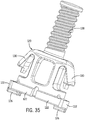
- FIG. 35 shows the base screw 120 in greater detail.
- the base screw 120 may include base screw snap fingers 130 that snap into the sidewall 115, contributing to a resilient, but rotatable mating connection with the housing mating portion 114.
- the base screw 120 may additionally include a threaded section 128, to which the retainer 118 connects.
- an O-Ring channel such as the O-Ring channel 23 shown in the previous embodiment, is no longer pertinent and may be eliminated from such an embodiment, which may decrease the overall length of the base screw.
- the base screw 120 is shown without an O-Ring channel, as this embodiment does not include an O-Ring.
- the base screw 120 may include an O-Ring channel, which may support an O-Ring capable of forming the desired seal between the housing mating portion 114 and the base screw 120 when the housing mating portion 114 mates with the base screw 120.
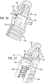
- FIGS. 36-37 show the retainer 118 in greater detail.
- the retainer 118 includes a semicircular retainer sidewall 140.
- the retainer sidewall 140 defines a clutching opening 142.
- a first pass core gap 144 may be defined in the retainer 118.
- the first pass core gap 144 may be sized to permit a limited amount of retainer spring finger 134 flexure, while maintaining sufficient retainer spring finger 134 structural strength and position within an adjustable travel length to avoid permanent deformation of the spring fingers 134.
- a second pass core gap 145 may be defined in the retainer 118.
- the second pass core gap 145 is defined between the retainer interface section 138 and the retainer spring fingers 134.
- the second pass core gap 145 may be sized to provide room for additional snap finger 134 flexure.
- the first pass core gap 144 and the second pass core gap 145 may form a pass core 143.
- the pass core 143 thus, may provide sufficient structure to maintain the mating function of the retainer spring fingers 134 and retainer snap fingers 132, while still allowing a sufficient level of retainer spring finger 134 flexure for installation and pivoting of the lamp mating portion 116.
- retainer sidewall 140 may be threaded to form a retainer interface section 138, where the retainer 118 may interact with the threaded section 128 of the base screw 120.
- the unique composition of the retainer sidewall 140 allows for clutching at any point throughout travel.
- the retainer sidewall 140 expands, widening the clutching opening 142 to an extent sufficient to permit slippage of the base screw 120 along the base screw interface 138 without significant damage to the threads of the threaded section 128 until the threaded section 128 once again fits properly within the retainer interface section 138, but not so far as to permit the threaded section 128 to dislodge from the retainer interface section 138.
- the pass core 143 is sized such that the retainer sidewall 140 maintains a sufficient degree of grip strength to prevent the base screw 120 from dislodging from the retainer 118. Integrated full-travel clutching provides a more robust adjustment solution for systems having increased weight and/or temperatures.
- the retainer 118 additionally includes retainer snap fingers 132 to engage the lamp mating panel 116 and retainer spring fingers 134 to secure the connection to the lamp mating panel 116.
- retainer snap fingers 132 there are two retainer snap fingers 132 and two retainer spring fingers 134, each retainer spring finger 134 located directly below a respective retainer snap finger 132. In other embodiments, there may be a greater number of retainer snap fingers 132 and/or retainer spring fingers 134. Direct engagement of the retainer 118 with the lamp mating panel 116 eliminates the need for installation of a secondary mating socket, simplifying assembly and reducing component count.
- both the retainer snap fingers 132 and the retainer spring fingers 134 are made of an elastic material. Securing the lamp mating panel 116 between multiple, elastic elements, versus a single element or small number of rigid elements, allows the adjuster assembly 110 both to withstand greater system vibrations with decreased likelihood of damage or dislodging, and to accommodate lamp mating panels, or equivalent lamp mating elements, of various thicknesses without requiring higher installation forces or creating a loose joint.
- This embodiment does not include travel restriction lugs as shown in the previously described embodiment, but travel restriction lugs could be included if desired.
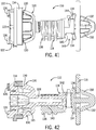
- FIGS. 38-42 show the various components of the full adjuster assembly 110 interacting with one another.
- the cutaway view in FIG. 39 shows housing mating portion 114 locked in place between the deformable fingers 122 and base screw snap fingers 130, as well as showing the lamp mating panel 116 locked in place by the retainer snap fingers 132 and further secured by the retainer spring fingers 134, also shown in the cross-sectional view in FIG. 42 .
- the custom fit of the retainer mating end within the mating geometry 124 helps control insertion location, promoting proper retainer 118 orientation, and aids in limiting unwanted vibration.
- FIGS. 43-46 illustrate how the lamp mating panel 116 tilts as the retainer 118 is retracted (as shown in FIGS. 43-44 ) or extended (as shown in FIGS. 45-46 ). Notice that the retainer 118 does not rotate as it extends or retracts, but rather, maintains a substantially constant orientation, with the clutching opening 142 facing outwards. This orientation ensures that general usage loads will occur on the retainer sidewall 140, rather than on or opposite the clutching opening 142, which helps prevent dislodging.
- the mating geometry 124 of the lamp mating panel 116 ensures this constant orientation, preventing substantial twisting of the retainer 118.
- the retainer 118 is caused to extend or retract by the interaction between the threaded section 128 of the base screw 120 and the retainer interface section 138 of the retainer 118 as the base screw 120 rotates.
- the rotational energy translates through the rotationally fixed retainer 118 to the lamp mating panel 116, causing the lamp mating panel 116 to pivot.
- the retainer 118 is in a retracted position (as shown in FIGS. 43-44 )
- the lamp mating panel 116 is tilted in a forward direction
- the retainer 118 is in an extended position (as shown in FIGS. 45-46 )
- the lamp mating panel 116 is tilted in a rearward direction.
Landscapes
- Engineering & Computer Science (AREA)
- Mechanical Engineering (AREA)
- General Engineering & Computer Science (AREA)
- Lighting Device Outwards From Vehicle And Optical Signal (AREA)
- Non-Portable Lighting Devices Or Systems Thereof (AREA)
Description
- The present invention relates generally to the field of adjusters. More particularly, the present invention relates to an adjuster for fog lamps, headlamps, and other forms of adjustable automotive lamps that allows clutching throughout travel.
- It is common, in automobiles, to use internal adjusters to adjust the position of certain automotive lamps, such as fog lamps or headlamps. Such internal adjusters include multiple parts and can easily grow complex. Hence, simplicity is an important facet when designing an adjuster. Additionally, lamp adjusters are often required to absorb high levels of system vibration, which can cause unwanted reorientation of the adjuster, damage to adjuster components, such as through stripping, and even, in some instances, disengagement of the adjuster. Therefore, it is valuable for an adjuster to be configured to maintain its orientation while undergoing system vibrations and to form a mating connection that is elastic enough to absorb vibrations without disengagement of or damage to either mated component. It may further be valuable for an adjuster to provide clutching throughout travel to eliminate stripping damage, especially in situations where it is required to accommodate higher system weights or operating temperatures.
-
WO2009/076438A1 describes a headlamp assembly including an adjusting mechanism for adjusting the aim of a headlamp. The mechanism includes a gear screw that is snap fit into the headlamp housing, a grommet positioned around the gear screw and snap fit into the headlamp reflector, and an O-ring.GB2285307A -
US5678915A describes a reflector with an electric lighting bulb mounted thereto coupled to a lamp body via a ball-and-socket connection and a vertical and a horizontal aiming screw. Each aiming screw comprises a threaded shank engaged with a nut on the back of the reflector, a journal joined to the threaded shank and rotatably received in a bearing sleeve formed on the lamp body, and a head portion joined to the journal and projecting rearwardly from the bearing sleeve. The aiming screw is formed to include two collars for engaging the bearing sleeve therebetween and so the aiming screw is restrained from axial displacement relative to the sleeve. The diameters of the various parts of the aiming screw and of the bearing sleeve are so determined in relation to one another that, in the assemblage of the headlamp, the aiming screw can be inserted, with its head portion foremost, into and through the bearing sleeve from inside the lamp body, either before or after coupling the aiming screw to the reflector via the nut. -
US2013/141930A1 describes a vehicular headlamp including a lamp body that has a cylindrical portion having a front opening and a rear opening; a translucent cover that covers the front opening, a metallic light source base that has a light source installation portion, which is inserted from the rear opening to the lamp body and disposed therein, an annular elastic body coupling the lamp body to the light source base and closing a clearance between the lamp body and the light source base, and an optical axis adjustment mechanism coupling the lamp body to the light source base, wherein the light source base is supported so as to be turnable with respect to the lamp body by operation of the optical axis adjustment mechanism, and the elastic body is configured to be elastically deformed as the light source base is turned with respect to the lamp body. - JPH08115064A describes an adjustment nut inserted from a clip board to a nut fixing hole to be fixed to the hole. A blade part of the board is bent in such a state as narrowing its angle of approximately V shape, passed the hole, and when it reaches a rear face it is enlarged by elasticity. The upper plane of a block body projecting face and the upper plane of the wing part projecting face are contacted with a surface and the rear face of the hole respectively so as to sandwich the board thickness with performing engagement. A size different in the board thickness is absorbed by deflection of the blade part and the nut is in an erecting state to the hole so that it can be held at a right position for threaded engagement with an adjustment screw, which is performed afterward.
- The present invention provides an adjuster for adjusting automotive lamps. In accordance with the invention such adjuster includes a retainer and a base screw configured in a manner that permits clutching throughout travel. Accordingly, in one embodiment, the present invention provides an adjuster for adjustable automotive lamps. The adjuster comprises a base screw and a retainer. The base screw includes a threaded shaft. The retainer connects to the threaded shaft and includes a semicircular sidewall, a plurality of retainer snap fingers, and a plurality of retainer spring fingers. The semicircular sidewall includes interior threads that correlate to the threads of the threaded shaft. The semicircular sidewall further surrounds at least a portion of the threaded shaft and defines a clutching opening. The clutching opening permits expansion of the semicircular sidewall when the threaded shaft slips with respect to the interior threads. The retainer snap fingers are located proximate to a distal end of the retainer and are configured to mate to a lamp mating portion of the adjustable automotive lamp. The retainer spring fingers are positioned within such proximity to the retainer snap fingers as to further secure the lamp mating portion against substantial sliding movement along the adjuster after the retainer snap fingers mate with the lamp mating portion. The retainer snap fingers and the retainer spring fingers flex relative to the semicircular sidewall.
- In another embodiment, the invention provides an adjuster assembly for adjustable automotive lamps. The adjuster assembly comprises a housing mating portion connected to a lamp housing, a lamp mating portion forming part of the adjustable automotive lamp, and a lamp adjuster connected to both the housing mating portion and the lamp mating portion. The lamp adjuster comprises a base screw and a retainer. The base screw includes a threaded shaft. The retainer connects to the threaded shaft and includes a semicircular sidewall, a plurality of retainer snap fingers, and a plurality of retainer spring fingers. The semicircular sidewall includes interior threads that correlate to the threads of the threaded shaft. The semicircular sidewall further surrounds at least a portion of the threaded shaft and defines a clutching opening. The clutching opening permits expansion of the semicircular sidewall when the threaded shaft slips with respect to the interior threads. The retainer snap fingers are located proximate to a distal end of the retainer and are configured to mate to a lamp mating portion of the adjustable automotive lamp. The retainer spring fingers are positioned within such proximity to the retainer snap fingers as to further secure the lamp mating portion against substantial sliding movement along the adjuster after the retainer snap fingers mate with the lamp mating portion. The retainer snap fingers and the retainer spring fingers flex relative to the semicircular sidewall.
- In a further embodiment, the invention provides the adjuster with a base screw comprising a plurality of base screw snap fingers configured to mate to a housing mating portion of a lamp housing in a manner that permits rotation of the base screw with respect the housing mating portion. The base screw also has a securement mechanism configured to secure the housing mating portion against substantial longitudinal movement after the plurality of base screw snap fingers mates with the housing mating portion and an orientation tab located on a distal end of the base screw. The orientation tab is configured to signal proper orientation of the adjuster to a user installing the adjuster. The plurality of retainer snap fingers and the plurality of retainer spring fingers comprise a pair of opposing retainer snap fingers, respectively a pair of opposing retainer spring fingers. The pair of retainer snap fingers are configured to mate to a lamp mating portion of an automotive lamp heat sink in a manner that fixes the retainer against rotation.
- Other objects and advantages of the present invention will become apparent hereinafter.
-
-
FIG. 1 is a perspective view of a clutching lamp adjuster assembly including a clutching lamp adjuster, a housing mating portion, and a lamp mating panel according to one embodiment of the present invention; -
FIG. 2 is a perspective view of the clutching lamp adjuster of the clutching lamp adjuster assembly ofFIG. 1 including a base screw, an O-Ring, and a retainer; -
FIG. 3 is an exploded side perspective view of the clutching lamp adjuster ofFIG. 2 ; -
FIG. 4 is an exploded side perspective view of the clutching lamp adjuster assembly ofFIG. 1 with the lamp mating panel removed for clarity, showing the clutching lamp adjuster as an assembled unit, and the housing mating portion, as a separate element, still to be assembled; -
FIG. 5 is an exploded side perspective view of the clutching lamp adjuster assembly ofFIG. 1 showing the clutching lamp adjuster and the housing mating portion together as an assembled unit, and the mating panel, as a separate element, still to be assembled; -
FIG. 6 is a top view of the clutching lamp adjuster assembly ofFIG. 1 with the lamp mating panel not shown; -
FIG. 7 is a top view of the clutching lamp adjuster assembly ofFIG. 1 ; -
FIG. 8 is a top view of the lamp mating panel of the clutching lamp adjuster assembly ofFIG. 1 ; -
FIG. 9 is a bottom view of the clutching lamp adjuster assembly ofFIG. 1 ; -
FIG. 10 is a bottom view of the housing mating portion of the clutching lamp adjuster assembly ofFIG. 1 ; -
FIG. 11 is a perspective view of the base screw of the clutching lamp adjuster shown inFIG. 2 ; -
FIG. 12 is a perspective view of the retainer of the clutching lamp adjuster shown inFIG. 2 ; -
FIG. 13 is a rotated perspective view of the retainer shown inFIG. 12 ; -
FIG. 14 is a front perspective view of the clutching lamp adjuster assembly ofFIG. 1 ; -
FIG. 15 is a front perspective cutaway view of the clutching lamp adjuster assembly ofFIG. 14 ; -
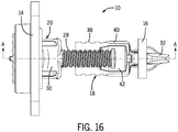
FIG. 16 is a side view of the clutching lamp adjuster assembly ofFIG. 1 ; -
FIG. 17 is a front view of the clutching lamp adjuster assembly ofFIG. 1 ; -
FIG. 18 is a cross-sectional front view of the clutching lamp adjuster assembly shown inFIG. 16 , taken along the line A-A inFIG. 16 ; -
FIG. 19 is a side view of a portion of the clutching lamp adjuster assembly in a retracted position; -
FIG. 20 is a detail side view of the clutching lamp adjuster assembly shown inFIG. 19 at the distal end of the retainer; -
FIG. 21 is a side view of the clutching lamp adjuster assembly in an extended position; -
FIG. 22 is a detail side view of a portion of the clutching lamp adjuster assembly shown in -
FIG. 21 at the distal end of the retainer; -
FIG. 23 is a perspective view of a clutching lamp adjuster assembly according to a second embodiment of the present invention including a clutching lamp adjuster and portions of a housing, and a lamp heat sink; -
FIG. 24 is a side view of the clutching lamp adjuster assembly shown inFIG. 23 ; -
FIG. 25 is a perspective view of the clutching lamp adjuster assembly ofFIG. 23 , showing the clutching lamp adjuster, the mating portion of the housing, and the mating panel of the lamp heat sink, with the remainder of the housing and of the lamp heat sink removed for clarity; -
FIG. 26 is a perspective view of the clutching lamp adjuster of the clutching lamp adjuster assembly shown inFIG. 25 including a base screw and a retainer; -
FIG. 27 is an exploded side perspective view of the clutching lamp adjuster shown inFIG. 26 ; -
FIG. 28 is an exploded side perspective view of the clutching lamp adjuster assembly shown in -
FIG. 25 with the lamp mating panel removed for clarity, showing the clutching lamp adjuster as an assembled unit, and the housing mating portion, as a separate element, yet to be assembled; -
FIG. 29 is an exploded side perspective view of the clutching lamp adjuster assembly shown in -
FIG. 25 showing the clutching lamp adjuster and the housing mating portion together as an assembled unit, and the mating panel, as a separate element, yet to be assembled; -
FIG. 30 is a top view of the clutching lamp adjuster assembly shown inFIG. 25 with the lamp mating panel removed for clarity; -
FIG. 31 is a top view of the clutching lamp adjuster assembly shown inFIG. 25 ; -
FIG. 32 is a top view of the lamp mating panel of the clutching lamp adjuster assembly shown inFIG. 25 ; -
FIG. 33 is a bottom view of the clutching lamp adjuster assembly shown inFIG. 25 ; -
FIG. 34 is a bottom view of the housing mating portion of the clutching lamp adjuster assembly shown inFIG. 25 ; -
FIG. 35 is a perspective view of the base screw of the clutching lamp adjuster shown inFIG. 26 ; -
FIG. 36 is a perspective view of the retainer of the clutching lamp adjuster shown inFIG. 26 ; -
FIG. 37 is a rotated perspective view of the retainer shown inFIG. 36 ; -
FIG. 38 is a front perspective view of the clutching lamp adjuster assembly shown inFIG. 25 ; -
FIG. 39 is a front perspective cutaway view of the clutching lamp adjuster assembly shown inFIG. 25 ; -
FIG. 40 is a side view of the clutching lamp adjuster assembly shown inFIG. 25 with the retainer in a neutral position; -
FIG. 41 is a front view of the clutching lamp adjuster assembly ofFIG. 40 ; -
FIG. 42 is a cross-sectional front view of the clutching lamp adjuster assembly shown inFIG. 40 , taken along the line B-B inFIG. 40 ; -
FIG. 43 is a side view of the clutching lamp adjuster assembly shown inFIG. 40 with the retainer in a retracted position; -
FIG. 44 is a detail side view of a portion of the clutching lamp adjuster assembly shown in -
FIG. 43 at the distal end of the retainer; -
FIG. 45 is a side view of the clutching lamp adjuster assembly shown inFIG. 40 with the retainer in an extended position; and -
FIG. 46 is a detail side view of a portion of the clutching lamp adjuster assembly shown inFIG. 45 at the distal end of the retainer. - While the description herein refers mainly to fog lamps, the term "fog lamp," as used in this application, can be applied equally well to other adjustable lamps, such as headlamps. References to fog lamps hereinafter should not be read as limiting the device for use solely with fog lamps.
-
FIG. 1 shows one embodiment of a clutching foglamp adjuster assembly 10. In the embodiment shown, theadjuster assembly 10 includes a clutchingfog lamp adjuster 12, ahousing mating portion 14, and alamp mating panel 16. Thehousing mating portion 14 may form a portion of a broader lamp housing, and thelamp mating panel 16 may form a portion of a broader lamp heat sink (not shown), but for convenience and clarity, the remainder of the housing and of the lamp heat sink are omitted from the drawings of this embodiment. In the present embodiment, theadjuster 12 includes abase screw 20, aretainer 18 that screws or snaps onto thebase screw 20, and an O-Ring 22 that wraps around a portion of the base screw 20 (seeFIG. 2 ). In this embodiment, theadjuster 12 mates with thehousing mating portion 14 at a housing mating end, and with thelamp mating panel 16 at an opposing, retainer mating end.FIG. 2 shows theadjuster 12 in greater detail. With thehousing mating portion 14 and thelamp mating panel 16 removed, the O-Ring 22 is now visible. -
FIGS. 3-6 show one manner of assembling theadjuster assembly 10.FIG. 3 is an exploded view of theadjuster 12. In the embodiment shown, thebase screw 20 includes an O-Ring channel 23 near the housing mating end of theadjuster 12. The O-Ring channel 23 allows for proper positioning of the O-Ring 22 and aids in maintain the position of the O-Ring 22 at the housing mating end of thebase screw 20.FIG. 4 shows theadjuster 12 fully assembled before being mated with thehousing mating portion 14. Here, the O-Ring 22 is positioned in the O-Ring channel 23, and theretainer 18 is snapped onto thebase screw 20. - A ridged
sidewall 15 defines an opening in thehousing mating portion 14, sized to permit theadjuster 12 to pass through the opening, beginning at the retainer mating end, until the opposing housing mating end is reached. At the housing mating end, thebase screw 20 snaps into place against the ridgedsidewall 15, such that thebase screw 20 may no longer move in a forward or a rearward direction through thehousing mating portion 14, but may still rotate within the opening defined by the ridgedsidewall 15. Although the ridgedsidewall 15, in this embodiment, forms a substantially circular shape, the ridged sidewall in other embodiments may form other shapes, corresponding to other mating ends of other base screws. In this embodiment, after theadjuster 12 is mated with thehousing mating portion 14, the O-Ring 22 may act as a seal, may aid in isolating vibrations, and/or may help to secure the connection between thebase screw 20 and thehousing mating portion 14. Other embodiments, such as the embodiment shown inFIGS. 23-46 , may operate without an O-Ring.FIG. 5 shows theadjuster 12 mated with thehousing mating portion 14, separated from thelamp mating panel 16. When fully assembled, thelamp mating panel 16 snaps into place at the retainer mating end of theadjuster 12. -
FIGS. 6-8 show top views of various elements of theadjuster assembly 10.FIG. 6 shows theadjuster 12 mated with thehousing mating portion 14. Thelamp mating panel 16 is not shown.FIG. 7 shows thecomplete adjuster assembly 10. AndFIG. 8 shows only thelamp mating panel 16. In this embodiment, themating geometry 24 is formed in the shape of a plus symbol. In other embodiments, the mating geometry may form other shapes, corresponding to other mating ends of other adjusters. -
FIGS. 9-10 respectively show bottom views of theadjuster assembly 10 and of thehousing mating portion 14, alone. In the embodiment shown, a distal end of thebase screw 20 includes a combination hexagonal-cross recessedinterface 25, which allows for multiple component installation and adjustment options. However, in other embodiments, the distal end of thebase screw 20 may include different forms of interfaces. In this embodiment, the distal end of thebase screw 20 additionally includesorientation tabs 26. Theorientation tabs 26 allow an assembler to correctly orient theadjuster 12, even when the assembler cannot see beyond thehousing mating portion 14, for instance, during a blind assembly. The embodiment shown inFIG. 9 includes twoorientation tabs 26, and proper installation is signaled by a horizontal orientation of theorientation tabs 26. However, in other embodiments, a different number of orientation tabs may be utilized and proper orientation of theadjuster 12 may be signaled by a different orientation of theorientation tabs 26. Further,FIG. 10 shows the ridgedsidewall 15 extending continuously around the opening formed inhousing mating portion 14. The continuity of the ridgedsidewall 15 may permit rotation of thebase screw 20 within thehousing mating portion 14. -
FIG. 11 shows thebase screw 20 in greater detail. Thebase screw 20 may include base screw snapfingers 30 that snap into the ridgedsidewall 15, contributing to a resilient, but rotatable mating connection with thehousing mating portion 14. Thebase screw 20 may additionally include a threadedsection 28, to which theretainer 18 connects. -
FIGS. 12-13 show theretainer 18 in greater detail. Theretainer 18 includes asemicircular retainer sidewall 40. In this embodiment, theretainer sidewall 40 defines a clutchingopening 42. Additionally, a portion of theretainer sidewall 40 may be threaded to form aretainer interface section 38, where theretainer 18 may interact with the threadedsection 28 of thebase screw 20. The unique composition of theretainer sidewall 40 allows for clutching at any point throughout travel. When thebase screw 20 rotates in a manner that would not otherwise be permitted by theretainer interface section 38, rather than stripping the threadedsection 28, theretainer sidewall 40 expands, widening the clutchingopening 42 to an extent sufficient to permit slippage of thebase screw 20 along thebase screw interface 38 without significant damage to the threads of the threadedsection 28 until the threadedsection 28 once again fits properly within theretainer interface section 38, but not so far as to permit the threadedsection 28 to dislodge from theretainer interface section 38. Integrated full-travel clutching provides a more robust adjustment solution for systems having increased weight and/or temperatures. - The
retainer 18 additionally includesretainer snap fingers 32 to engage thelamp mating panel 16 andretainer spring fingers 34 to secure the connection to thelamp mating panel 16. In the embodiment shown, there are tworetainer snap fingers 32 and tworetainer spring fingers 34, eachretainer spring finger 34 located directly below a respectiveretainer snap finger 32. In other embodiments, there may be a greater number ofretainer snap fingers 32 and/orretainer spring fingers 34. Direct engagement of theretainer 18 with thelamp mating panel 16 eliminates the need for installation of a secondary mating socket, simplifying assembly and reducing component count. - In this embodiment, both the
retainer snap fingers 32 and theretainer spring fingers 34 are made of an elastic material. Securing thelamp mating panel 16 between multiple, elastic elements, versus a single element or small number of rigid elements, allows theadjuster assembly 10 both to withstand greater system vibrations with decreased likelihood of damage or dislodging, and to accommodate lamp mating panels, or equivalent lamp mating elements, of various thicknesses without requiring higher installation forces or creating a loose joint. Finally, atravel restriction lug 36 may be attached to theretainer sidewall 40 directly below eachretainer spring finger 34. Thetravel restriction lug 36 limits the distance that the correspondingretainer spring finger 34 may be stretched during installation and general usage, reducing the risk of permanent spring finger deformation. -
FIGS. 14-18 show the various components of thefull adjuster assembly 10 interacting with one another. For instance, the cutaway view inFIG. 15 shows the O-Ring 22 in place between thebase screw 20 and the ridgedsidewall 15, as well as showing thelamp mating panel 16 locked in place by theretainer snap fingers 32 and further secured by theretainer spring finger 34, also shown in the cross-sectional view inFIG. 18 . Further, the custom fit of the retainer mating end within the mating geometry 24 (shown inFIG. 8 ) helps control insertion location, promotingproper retainer 18 orientation, and aids in limiting unwanted vibration. Additionally, the ability to connect the mating end of theretainer 18 directly to thelamp mating panel 16 of the lamp heat sink, due to the mating geometry 24 (shown inFIG. 8 ), eliminates the need for additional mating components, such as a secondary mating component, simplifying theadjuster assembly 10. -
FIGS. 19-22 illustrate how thelamp mating panel 16 tilts as theretainer 18 is retracted (as shown inFIGS. 19-20 ) or extended (as shown inFIGS. 21-22 ). Notice that theretainer 18 does not rotate as it extends or retracts, but rather, maintains a substantially constant orientation, with the clutchingopening 42 facing outwards. This orientation ensures that general usage loads will occur on theretainer sidewall 40, rather than on or opposite the clutchingopening 42, which helps prevent dislodging. Themating geometry 24 of thelamp mating panel 16 ensures this constant orientation, preventing substantial twisting of theretainer 18. - In the present embodiment, the
retainer 18 is caused to extend or retract by the interaction between the threadedsection 28 of thebase screw 20 and theretainer interface section 38 of theretainer 18 as thebase screw 20 rotates. Here, when thebase screw 20 rotates, the rotational energy translates through the rotationally fixedretainer 18 to thelamp mating panel 16, causing thelamp mating panel 16 to pivot. In this embodiment, when theretainer 18 is in a retracted position (as shown inFIGS. 19-20 ), thelamp mating panel 16 is tilted in a forward direction, whereas when theretainer 18 is in an extended position (as shown inFIGS. 21-22 ), thelamp mating panel 16 is tilted in a rearward direction. -
FIGS. 23-24 show a clutching foglamp adjuster assembly 110 according to a second embodiment of the present invention, with expanded views of alamp housing 104 and alamp heat sink 106 shown. Ahousing mating portion 114 is attached to thehousing 104, and alamp mating portion 116 is attached to thelamp heat sink 106. In this embodiment, thehousing mating portion 114 is formed as a part of thehousing 104 and thelamp mating panel 116 is formed as a part of thelamp heat sink 106, although other means of attachment could be implemented. Additionally, while thelamp mating panel 116 is shown in this embodiment to resemble a flat panel, in other embodiments, the mating portion of the lamp heat sink may take on other shapes. In the present embodiment, the clutchinglamp adjuster 112 connects to both thehousing 104, at thehousing mating portion 114, and to thelamp heat sink 106, at thelamp mating panel 116. -
FIG. 25 shows the clutchinglamp adjuster assembly 110 including the clutchinglamp adjuster 112, thehousing mating portion 114, and thelamp mating panel 116. The remainder of thehousing 104 andlamp heat sink 106 are removed for clarity in this and the remaining figures. In this embodiment, theadjuster 112 mates with thehousing mating portion 114 at a housing mating end, and with thelamp mating panel 116 at an opposing, retainer mating end.FIG. 26 shows theadjuster 112 in greater detail, with thehousing mating portion 114 and thelamp mating panel 116 removed. In the present embodiment, theadjuster 112 includes abase screw 120 and aretainer 118 that screws or snaps onto thebase screw 120. -
FIGS. 27-29 show one manner of assembling theadjuster assembly 110.FIG. 27 is an exploded view of theadjuster 112.FIG. 28 shows theadjuster 112 fully assembled, with theretainer 118 snapped onto thebase screw 120, before being mated with thehousing mating portion 114. Asidewall 115 defines an opening in thehousing mating portion 114, sized to permit theadjuster 112 to pass through the opening, beginning at the retainer mating end, until the opposing housing mating end is reached. At the housing mating end, thebase screw 120 snaps into place against thesidewall 115, such that thebase screw 120 may no longer move in a forward or a rearward direction through thehousing mating portion 114, but may still rotate within the opening defined by thesidewall 115. Although thesidewall 115, in this embodiment, forms a substantially circular shape, the sidewall in other embodiments may form other shapes, corresponding to other mating ends of other base screws. Further, the present embodiment depicts anadjuster assembly 110 in which no seal is required between thehousing mating portion 114 and thebase screw 120. Therefore, an O-ring is not included in this embodiment. However, should a seal be desired between thehousing mating portion 114 and thebase screw 120, an O-ring, for instance an O-ring similar to the O-Ring 22 shown and described in the previous embodiment, may be included in this embodiment.FIG. 29 shows theadjuster 112 mated with thehousing mating portion 114, but separated from thelamp mating panel 116. When fully assembled, thelamp mating panel 116 snaps into place at the retainer mating end of theadjuster 112. -
FIGS. 30-32 show top views of various elements of theadjuster assembly 110.FIG. 30 shows theadjuster 112 mated with thehousing mating portion 114. Thelamp mating panel 116 is not shown.FIG. 31 shows thecomplete adjuster assembly 110. AndFIG. 32 shows only thelamp mating panel 116. In this embodiment, themating geometry 124 is formed in the shape of a plus symbol. In other embodiments, the mating geometry may form other shapes, corresponding to other mating ends of other adjusters. -
FIGS. 33-34 respectively show bottom views of theadjuster assembly 110 and of thehousing mating portion 114, alone. In the embodiment shown, a distal end of thebase screw 120 includes a combination hexagonal-cross recessedinterface 125, which allows for multiple component installation and adjustment options. However, in other embodiments, the distal end of thebase screw 120 may include different forms of interfaces. The distal end of thebase screw 120 may further includedeformable fingers 122, which aid in securing thebase screw 120 to thehousing mating portion 114. As can be seen inFIG. 33 , thedeformable fingers 122 extend beyond the opening defined by thesidewall 115, such that thehousing mating portion 114 may not be moved in a rearward direction beyond thedeformable fingers 122. Thedeformable fingers 122 are sufficiently deformable to absorb system vibrations without breaking from thebase screw 120, but maintain sufficient rigidity to prevent disconnection of thehousing portion 114 from thebase screw 120. - In this embodiment, the distal end of the
base screw 120 additionally includesorientation tabs 126. Theorientation tabs 126 allow an assembler to correctly orient theadjuster 112, even when the assembler cannot see beyond thehousing mating portion 114, for instance, during a blind assembly. The embodiment shown inFIG. 33 includes twoorientation tabs 126, and proper installation is signaled by a horizontal orientation of theorientation tabs 126. However, in other embodiments, a different number of orientation tabs may be utilized and proper orientation of theadjuster 112 may be signaled by a different orientation of theorientation tabs 126. Further,FIG. 34 shows thesidewall 115 extending continuously around the opening formed inhousing mating portion 114. The continuity of thesidewall 115 may permit rotation of thebase screw 120 within thehousing mating portion 114. -
FIG. 35 shows thebase screw 120 in greater detail. Thebase screw 120 may include base screw snapfingers 130 that snap into thesidewall 115, contributing to a resilient, but rotatable mating connection with thehousing mating portion 114. Thebase screw 120 may additionally include a threadedsection 128, to which theretainer 118 connects. In an embodiment that does not include an O-Ring, an O-Ring channel, such as the O-Ring channel 23 shown in the previous embodiment, is no longer pertinent and may be eliminated from such an embodiment, which may decrease the overall length of the base screw. - For instance, in
FIG. 35 , thebase screw 120 is shown without an O-Ring channel, as this embodiment does not include an O-Ring. Should a seal be desired between thehousing mating portion 114 and thebase screw 120, thebase screw 120 may include an O-Ring channel, which may support an O-Ring capable of forming the desired seal between thehousing mating portion 114 and thebase screw 120 when thehousing mating portion 114 mates with thebase screw 120. -
FIGS. 36-37 show theretainer 118 in greater detail. Theretainer 118 includes asemicircular retainer sidewall 140. In the present embodiment, theretainer sidewall 140 defines a clutchingopening 142. Above the clutchingopening 142, a firstpass core gap 144 may be defined in theretainer 118. The firstpass core gap 144 may be sized to permit a limited amount ofretainer spring finger 134 flexure, while maintaining sufficientretainer spring finger 134 structural strength and position within an adjustable travel length to avoid permanent deformation of thespring fingers 134. Opposite from and, at least in part aligned with, the firstpass core gap 144, a secondpass core gap 145 may be defined in theretainer 118. In this embodiment, the secondpass core gap 145 is defined between theretainer interface section 138 and theretainer spring fingers 134. The secondpass core gap 145 may be sized to provide room foradditional snap finger 134 flexure. Together, the firstpass core gap 144 and the secondpass core gap 145 may form apass core 143. Thepass core 143, thus, may provide sufficient structure to maintain the mating function of theretainer spring fingers 134 and retainer snapfingers 132, while still allowing a sufficient level ofretainer spring finger 134 flexure for installation and pivoting of thelamp mating portion 116. - Additionally, a portion of the
retainer sidewall 140 may be threaded to form aretainer interface section 138, where theretainer 118 may interact with the threadedsection 128 of thebase screw 120. The unique composition of theretainer sidewall 140 allows for clutching at any point throughout travel. When thebase screw 120 rotates in a manner that would not otherwise be permitted by theretainer interface section 138, rather than stripping the threadedsection 128, theretainer sidewall 140 expands, widening the clutchingopening 142 to an extent sufficient to permit slippage of thebase screw 120 along thebase screw interface 138 without significant damage to the threads of the threadedsection 128 until the threadedsection 128 once again fits properly within theretainer interface section 138, but not so far as to permit the threadedsection 128 to dislodge from theretainer interface section 138. Thepass core 143 is sized such that theretainer sidewall 140 maintains a sufficient degree of grip strength to prevent thebase screw 120 from dislodging from theretainer 118. Integrated full-travel clutching provides a more robust adjustment solution for systems having increased weight and/or temperatures. - The
retainer 118 additionally includesretainer snap fingers 132 to engage thelamp mating panel 116 andretainer spring fingers 134 to secure the connection to thelamp mating panel 116. In the embodiment shown, there are tworetainer snap fingers 132 and tworetainer spring fingers 134, eachretainer spring finger 134 located directly below a respectiveretainer snap finger 132. In other embodiments, there may be a greater number ofretainer snap fingers 132 and/orretainer spring fingers 134. Direct engagement of theretainer 118 with thelamp mating panel 116 eliminates the need for installation of a secondary mating socket, simplifying assembly and reducing component count. - In this embodiment, both the
retainer snap fingers 132 and theretainer spring fingers 134 are made of an elastic material. Securing thelamp mating panel 116 between multiple, elastic elements, versus a single element or small number of rigid elements, allows theadjuster assembly 110 both to withstand greater system vibrations with decreased likelihood of damage or dislodging, and to accommodate lamp mating panels, or equivalent lamp mating elements, of various thicknesses without requiring higher installation forces or creating a loose joint. This embodiment does not include travel restriction lugs as shown in the previously described embodiment, but travel restriction lugs could be included if desired. -
FIGS. 38-42 show the various components of thefull adjuster assembly 110 interacting with one another. For instance, the cutaway view inFIG. 39 showshousing mating portion 114 locked in place between thedeformable fingers 122 and base screw snapfingers 130, as well as showing thelamp mating panel 116 locked in place by theretainer snap fingers 132 and further secured by theretainer spring fingers 134, also shown in the cross-sectional view inFIG. 42 . Further, the custom fit of the retainer mating end within the mating geometry 124 (shown inFIG. 32 ) helps control insertion location, promotingproper retainer 118 orientation, and aids in limiting unwanted vibration. Additionally, the ability to connect the mating end of theretainer 118 directly to thelamp mating panel 116 of thelamp heat sink 106, due to the mating geometry 124 (shown inFIG. 32 ), eliminates the need for additional mating components, such as a secondary mating component, simplifying theadjuster assembly 110. -
FIGS. 43-46 illustrate how thelamp mating panel 116 tilts as theretainer 118 is retracted (as shown inFIGS. 43-44 ) or extended (as shown inFIGS. 45-46 ). Notice that theretainer 118 does not rotate as it extends or retracts, but rather, maintains a substantially constant orientation, with the clutchingopening 142 facing outwards. This orientation ensures that general usage loads will occur on theretainer sidewall 140, rather than on or opposite the clutchingopening 142, which helps prevent dislodging. Themating geometry 124 of thelamp mating panel 116 ensures this constant orientation, preventing substantial twisting of theretainer 118. - In the present embodiment, the
retainer 118 is caused to extend or retract by the interaction between the threadedsection 128 of thebase screw 120 and theretainer interface section 138 of theretainer 118 as thebase screw 120 rotates. Here, when thebase screw 120 rotates, the rotational energy translates through the rotationally fixedretainer 118 to thelamp mating panel 116, causing thelamp mating panel 116 to pivot. In this embodiment, when theretainer 118 is in a retracted position (as shown inFIGS. 43-44 ), thelamp mating panel 116 is tilted in a forward direction, whereas when theretainer 118 is in an extended position (as shown inFIGS. 45-46 ), thelamp mating panel 116 is tilted in a rearward direction. - Although the invention has been herein described in what is perceived to be the most practical and preferred embodiments, it is to be understood that the invention is not intended to be limited to the specific embodiments set forth above. Rather, it is recognized that modifications may be made by one of skill in the art of the invention within the scope of the invention as defined by the appended claims.
Claims (15)
- An adjuster (12, 112) for adjustable automotive lamps, the adjuster comprising:a base screw (20, 120) including a threaded shaft; anda retainer (18, 118) connected to the threaded shaft, the retainer comprising:a semicircular sidewall (40, 140), partially surrounding at least a portion of the threaded shaft, the semicircular sidewall having interior threads that correlate to the threads of the threaded shaft, and the semicircular sidewall defining a clutching opening that permits expansion of the semicircular sidewall when the threaded shaft slips with respect to the interior threads;a plurality of retainer snap fingers (32, 132) located proximate to a distal end of the retainer (18, 118) and configured to mate to a lamp mating portion (16, 116) of the adjustable automotive lamp; anda plurality of retainer spring fingers (34, 134) positioned within such proximity to the plurality of retainer snap fingers (32, 132) as to further secure the lamp mating portion (16, 116) against substantial sliding movement along the adjuster after the plurality of retainer snap fingers mates with the lamp mating portion;characterised in that the retainer snap fingers (32, 132) and retainer spring fingers (34, 134) are configured to flex relative to the semicircular sidewall (40, 140) as the retainer snap fingers (32, 132) and the retainer spring fingers (34, 134) mate with the lamp mating portion (16, 116).
- The adjuster of claim 1, wherein the base screw (20, 120) further comprises a plurality of base screw snap fingers (30, 130) configured to mate to a housing mating portion (14, 114) of a lamp housing in a manner that permits rotation of the base screw with respect to the housing mating portion.
- The adjuster of claim 2, wherein the base screw (20, 120) further comprises a securement mechanism configured to secure the housing mating portion of a lamp housing against substantial longitudinal movement after the plurality of base screw snap fingers (30, 130) mates with the housing mating portion.
- The adjuster of claim 2 or of claim 3, wherein the base screw (20) further comprises an O-Ring (22) coaxially affixed to the base screw, the O-Ring (22) configured to form a seal between the base screw and the housing mating portion (14) when the base screw mates to the housing mating portion, and when dependent on claim 3 optionally wherein the securement mechanism comprises the O-ring, and further optionally the adjuster further comprising a pair of travel restriction lugs (36) positioned on an opposing side of the retainer spring fingers (34) from the retainer snap fingers (32), each travel restriction lug (36) of the pair of travel restriction lugs positioned sufficiently proximate to the spring fingers to prevent overextension of each respective spring finger of the spring fingers.
- The adjuster of claim 2 or of claim 3, wherein the base screw (120) further comprises a deformable finger (122) positioned at a distal end of the base screw within such proximity to the plurality of base screw snap fingers as to further secure the housing mating portion (114) against substantial longitudinal sliding movement after the plurality of snap fingers (130) mates with the housing mating portion, and when dependent on claim 3 optionally wherein the securement mechanism comprises the deformable finger.
- The adjuster of claim 5, wherein:-(i) the deformable finger (122) elastically deforms sufficiently to absorb system vibrations without breaking from the base screw (120) during use; and/or(ii) the semicircular sidewall (140) further comprises an unthreaded portion positioned between the interior threads and the retainer spring fingers (134), and wherein the unthreaded portion defines a gap opposite, at least in part, to the clutching opening.
- The adjuster of any preceding claim, wherein the plurality of retainer snap fingers comprises a pair of opposing retainer snap fingers (32, 132), and optionally wherein the pair of opposing retainer snap fingers (32, 132) is configured to mate to the lamp mating portion (16, 116) being attached to an automotive lamp heat sink in a manner that fixes the retainer against rotation.
- The adjuster of any preceding claim, wherein the plurality of retainer spring fingers comprises a pair of opposing retainer spring fingers (34, 134).
- The adjuster of any preceding claim, further comprising an orientation tab (26, 126) located on a distal end of the base screw (20, 120), configured to signal proper orientation of the adjuster to a user installing the adjuster.
- An adjuster assembly (10, 110) for adjustable automotive lamps, the adjuster assembly comprising:a lamp housing mating portion (14, 114);a lamp mating portion (16, 116); anda lamp adjuster (12, 112) according to claim 1, connected to both the housing mating portion and the lamp mating portion.
- The adjuster assembly of claim 10, wherein the lamp mating portion (16, 116) includes lamp mating geometry configured to restrict rotation of the retainer (18, 118) with respect to the lamp mating portion while permitting pivoting of the lamp mating portion with respect to the retainer.
- The adjuster assembly of claim 11, wherein:-(i) the lamp mating geometry comprises a plus shape; and/or(ii) the base screw (20, 120) further comprises a plurality of base screw snap fingers (30, 130) configured to mate to the housing mating portion (14, 114).
- The adjuster assembly of claim 12, part (ii), wherein the housing mating portion (14, 114) includes housing mating geometry configured to permit rotation of the base screw (20, 120) with respect to the housing mating portion.
- The adjuster assembly of claim 13, wherein:-(i) the base screw (20) further comprises an O-Ring (22), affixed around the base screw at the location where the base screw mates with the housing mating portion (14), the O-Ring forming a seal between the base screw and the housing mating portion; and/or(ii) the base screw (120) further comprises a deformable finger (122) positioned at a distal end of the base screw within such proximity to the plurality of base screw snap fingers as to secure the housing mating portion (114) against longitudinal movement, and optionally or preferably wherein the deformable finger elastically deforms sufficiently to absorb system vibrations without breaking from the base screw during use.
- The adjuster assembly of any of claims 10 to 14, wherein the lamp mating portion (16, 116) comprises a panel.
Applications Claiming Priority (2)
| Application Number | Priority Date | Filing Date | Title |
|---|---|---|---|
| US201862697853P | 2018-07-13 | 2018-07-13 | |
| US16/506,638 US10793058B2 (en) | 2018-07-13 | 2019-07-09 | Clutching lamp adjuster |
Publications (2)
| Publication Number | Publication Date |
|---|---|
| EP3611048A1 EP3611048A1 (en) | 2020-02-19 |
| EP3611048B1 true EP3611048B1 (en) | 2021-09-01 |
Family
ID=69138607
Family Applications (1)
| Application Number | Title | Priority Date | Filing Date |
|---|---|---|---|
| EP19185561.8A Active EP3611048B1 (en) | 2018-07-13 | 2019-07-10 | Clutching lamp adjuster |
Country Status (4)
| Country | Link |
|---|---|
| US (1) | US10793058B2 (en) |
| EP (1) | EP3611048B1 (en) |
| CN (1) | CN110712586B (en) |
| ES (1) | ES2901392T3 (en) |
Cited By (1)
| Publication number | Priority date | Publication date | Assignee | Title |
|---|---|---|---|---|
| DE102023111102A1 (en) | 2023-04-28 | 2024-10-31 | Ejot Se & Co. Kg | assembly for providing a connection point |
Family Cites Families (14)
| Publication number | Priority date | Publication date | Assignee | Title |
|---|---|---|---|---|
| US3574899A (en) * | 1969-09-04 | 1971-04-13 | Illinois Tool Works | Snap fastener |
| US5063481A (en) * | 1990-10-15 | 1991-11-05 | Eaton Corporation | Pivot assembly for vehicle headlight position adjustment |
| US5258894A (en) * | 1992-12-11 | 1993-11-02 | Illinois Tool Works Inc. | Snap-in headlamp adjustment assembly |
| US5526238A (en) | 1992-12-28 | 1996-06-11 | Ford Motor Company | Adjusting and support apparatus for a lamp unit |
| GB2285307B (en) | 1993-12-21 | 1997-11-12 | Koito Mfg Co Ltd | Vehicular headlamp |
| JP2847347B2 (en) | 1994-10-14 | 1999-01-20 | スタンレー電気株式会社 | Optical axis adjustment device |
| JP3074557B2 (en) | 1994-11-24 | 2000-08-07 | 株式会社小糸製作所 | Vehicle headlamp |
| US5497301A (en) * | 1995-02-13 | 1996-03-05 | General Motors Corporation | Headlamp adjustment mechanism |
| JP3250598B2 (en) | 1995-06-28 | 2002-01-28 | 株式会社小糸製作所 | Self-locking nut |
| US8684574B2 (en) * | 2007-12-13 | 2014-04-01 | Burton Technologies, Llc | Gear screw adjuster |
| CN201895611U (en) * | 2010-11-30 | 2011-07-13 | 奇瑞汽车股份有限公司 | Adjusting mechanism for automobile headlight reflector |
| JP5898937B2 (en) | 2011-12-05 | 2016-04-06 | 株式会社小糸製作所 | Vehicle headlamp |
| US20150017662A1 (en) | 2012-01-27 | 2015-01-15 | University-Industry Cooperation Group fo Kyung Hee University | Method for detecting and quantifying a target protein or a target cell using an aptamer chip |
| US10093221B2 (en) * | 2015-07-07 | 2018-10-09 | Burton Technologies, Llc | Light module fastening assembly having a snap wedge assembly with ball stud and insert |
-
2019
- 2019-07-09 US US16/506,638 patent/US10793058B2/en active Active
- 2019-07-10 EP EP19185561.8A patent/EP3611048B1/en active Active
- 2019-07-10 ES ES19185561T patent/ES2901392T3/en active Active
- 2019-07-12 CN CN201910632991.8A patent/CN110712586B/en active Active
Cited By (2)
| Publication number | Priority date | Publication date | Assignee | Title |
|---|---|---|---|---|
| DE102023111102A1 (en) | 2023-04-28 | 2024-10-31 | Ejot Se & Co. Kg | assembly for providing a connection point |
| WO2024223937A1 (en) | 2023-04-28 | 2024-10-31 | Ejot Se & Co. Kg | Assembly for providing a connection point |
Also Published As
| Publication number | Publication date |
|---|---|
| ES2901392T3 (en) | 2022-03-22 |
| CN110712586B (en) | 2023-03-14 |
| US20200017019A1 (en) | 2020-01-16 |
| EP3611048A1 (en) | 2020-02-19 |
| CN110712586A (en) | 2020-01-21 |
| US10793058B2 (en) | 2020-10-06 |
Similar Documents
| Publication | Publication Date | Title |
|---|---|---|
| US5678915A (en) | Easy-to-assemble aiming mechanism for vehicle lamps | |
| JP2001256806A (en) | Reflector movable type headlamp for automobile | |
| EP2865567B1 (en) | Reflector damper bracket | |
| US11293480B2 (en) | Ball channel assembly | |
| EP3611048B1 (en) | Clutching lamp adjuster | |
| EP2724888A2 (en) | Vehicle headlamp | |
| AU2022272474A1 (en) | Tilt head for high load display support system | |
| EP1419934A1 (en) | Adjustment device of electric power mirrors | |
| JP6674926B2 (en) | Angle adjustment device | |
| JP2001351407A (en) | Headlamp for automobile with movable reflector | |
| WO2019088109A1 (en) | Fixation structure | |
| JP3217213B2 (en) | Aiming screw support structure | |
| KR102186601B1 (en) | Appliance having knob assembly | |
| US6338567B1 (en) | Gearless headlamp adjustor | |
| US20070053196A1 (en) | Sliding adjuster | |
| US7438457B2 (en) | Input shaft for a lamp adjuster | |
| CN101351651A (en) | installation structure | |
| EP3584458A1 (en) | Ball stud track assembly | |
| CN107166289B (en) | Lighting lamp for vehicle | |
| CN114945754A (en) | Joint assembly with receiving mechanism and ball hinge | |
| US7572042B2 (en) | Leveling device for vehicular headlamp | |
| CN102089841A (en) | switch attachment kit | |
| US20230272812A1 (en) | Cover Fastening System for a Vehicle | |
| JP2006513095A (en) | 180 degree adjuster | |
| EP3587183A1 (en) | Lighting module adjuster and automotive lighting device |
Legal Events
| Date | Code | Title | Description |
|---|---|---|---|
| PUAI | Public reference made under article 153(3) epc to a published international application that has entered the european phase |
Free format text: ORIGINAL CODE: 0009012 |
|
| STAA | Information on the status of an ep patent application or granted ep patent |
Free format text: STATUS: THE APPLICATION HAS BEEN PUBLISHED |
|
| AK | Designated contracting states |
Kind code of ref document: A1 Designated state(s): AL AT BE BG CH CY CZ DE DK EE ES FI FR GB GR HR HU IE IS IT LI LT LU LV MC MK MT NL NO PL PT RO RS SE SI SK SM TR |
|
| AX | Request for extension of the european patent |
Extension state: BA ME |
|
| STAA | Information on the status of an ep patent application or granted ep patent |
Free format text: STATUS: REQUEST FOR EXAMINATION WAS MADE |
|
| 17P | Request for examination filed |
Effective date: 20200618 |
|
| RBV | Designated contracting states (corrected) |
Designated state(s): AL AT BE BG CH CY CZ DE DK EE ES FI FR GB GR HR HU IE IS IT LI LT LU LV MC MK MT NL NO PL PT RO RS SE SI SK SM TR |
|
| RIC1 | Information provided on ipc code assigned before grant |
Ipc: B60Q 1/068 20060101AFI20200924BHEP |
|
| GRAP | Despatch of communication of intention to grant a patent |
Free format text: ORIGINAL CODE: EPIDOSNIGR1 |
|
| STAA | Information on the status of an ep patent application or granted ep patent |
Free format text: STATUS: GRANT OF PATENT IS INTENDED |
|
| INTG | Intention to grant announced |
Effective date: 20201105 |
|
| GRAJ | Information related to disapproval of communication of intention to grant by the applicant or resumption of examination proceedings by the epo deleted |
Free format text: ORIGINAL CODE: EPIDOSDIGR1 |
|
| STAA | Information on the status of an ep patent application or granted ep patent |
Free format text: STATUS: REQUEST FOR EXAMINATION WAS MADE |
|
| INTC | Intention to grant announced (deleted) | ||
| GRAP | Despatch of communication of intention to grant a patent |
Free format text: ORIGINAL CODE: EPIDOSNIGR1 |
|
| STAA | Information on the status of an ep patent application or granted ep patent |
Free format text: STATUS: GRANT OF PATENT IS INTENDED |
|
| INTG | Intention to grant announced |
Effective date: 20210315 |
|
| GRAS | Grant fee paid |
Free format text: ORIGINAL CODE: EPIDOSNIGR3 |
|
| GRAA | (expected) grant |
Free format text: ORIGINAL CODE: 0009210 |
|
| STAA | Information on the status of an ep patent application or granted ep patent |
Free format text: STATUS: THE PATENT HAS BEEN GRANTED |
|
| AK | Designated contracting states |
Kind code of ref document: B1 Designated state(s): AL AT BE BG CH CY CZ DE DK EE ES FI FR GB GR HR HU IE IS IT LI LT LU LV MC MK MT NL NO PL PT RO RS SE SI SK SM TR |
|
| REG | Reference to a national code |
Ref country code: GB Ref legal event code: FG4D |
|
| REG | Reference to a national code |
Ref country code: CH Ref legal event code: EP Ref country code: AT Ref legal event code: REF Ref document number: 1425902 Country of ref document: AT Kind code of ref document: T Effective date: 20210915 |
|
| REG | Reference to a national code |
Ref country code: DE Ref legal event code: R096 Ref document number: 602019007295 Country of ref document: DE |
|
| REG | Reference to a national code |
Ref country code: IE Ref legal event code: FG4D |
|
| REG | Reference to a national code |
Ref country code: LT Ref legal event code: MG9D |
|
| REG | Reference to a national code |
Ref country code: NL Ref legal event code: MP Effective date: 20210901 |
|
| PG25 | Lapsed in a contracting state [announced via postgrant information from national office to epo] |
Ref country code: BG Free format text: LAPSE BECAUSE OF FAILURE TO SUBMIT A TRANSLATION OF THE DESCRIPTION OR TO PAY THE FEE WITHIN THE PRESCRIBED TIME-LIMIT Effective date: 20211201 Ref country code: LT Free format text: LAPSE BECAUSE OF FAILURE TO SUBMIT A TRANSLATION OF THE DESCRIPTION OR TO PAY THE FEE WITHIN THE PRESCRIBED TIME-LIMIT Effective date: 20210901 Ref country code: NO Free format text: LAPSE BECAUSE OF FAILURE TO SUBMIT A TRANSLATION OF THE DESCRIPTION OR TO PAY THE FEE WITHIN THE PRESCRIBED TIME-LIMIT Effective date: 20211201 Ref country code: HR Free format text: LAPSE BECAUSE OF FAILURE TO SUBMIT A TRANSLATION OF THE DESCRIPTION OR TO PAY THE FEE WITHIN THE PRESCRIBED TIME-LIMIT Effective date: 20210901 Ref country code: RS Free format text: LAPSE BECAUSE OF FAILURE TO SUBMIT A TRANSLATION OF THE DESCRIPTION OR TO PAY THE FEE WITHIN THE PRESCRIBED TIME-LIMIT Effective date: 20210901 Ref country code: SE Free format text: LAPSE BECAUSE OF FAILURE TO SUBMIT A TRANSLATION OF THE DESCRIPTION OR TO PAY THE FEE WITHIN THE PRESCRIBED TIME-LIMIT Effective date: 20210901 Ref country code: FI Free format text: LAPSE BECAUSE OF FAILURE TO SUBMIT A TRANSLATION OF THE DESCRIPTION OR TO PAY THE FEE WITHIN THE PRESCRIBED TIME-LIMIT Effective date: 20210901 |
|
| REG | Reference to a national code |
Ref country code: AT Ref legal event code: MK05 Ref document number: 1425902 Country of ref document: AT Kind code of ref document: T Effective date: 20210901 |
|
| PG25 | Lapsed in a contracting state [announced via postgrant information from national office to epo] |
Ref country code: PL Free format text: LAPSE BECAUSE OF FAILURE TO SUBMIT A TRANSLATION OF THE DESCRIPTION OR TO PAY THE FEE WITHIN THE PRESCRIBED TIME-LIMIT Effective date: 20210901 Ref country code: LV Free format text: LAPSE BECAUSE OF FAILURE TO SUBMIT A TRANSLATION OF THE DESCRIPTION OR TO PAY THE FEE WITHIN THE PRESCRIBED TIME-LIMIT Effective date: 20210901 Ref country code: GR Free format text: LAPSE BECAUSE OF FAILURE TO SUBMIT A TRANSLATION OF THE DESCRIPTION OR TO PAY THE FEE WITHIN THE PRESCRIBED TIME-LIMIT Effective date: 20211202 |
|
| REG | Reference to a national code |
Ref country code: ES Ref legal event code: FG2A Ref document number: 2901392 Country of ref document: ES Kind code of ref document: T3 Effective date: 20220322 |
|
| PG25 | Lapsed in a contracting state [announced via postgrant information from national office to epo] |
Ref country code: AT Free format text: LAPSE BECAUSE OF FAILURE TO SUBMIT A TRANSLATION OF THE DESCRIPTION OR TO PAY THE FEE WITHIN THE PRESCRIBED TIME-LIMIT Effective date: 20210901 |
|
| PG25 | Lapsed in a contracting state [announced via postgrant information from national office to epo] |
Ref country code: IS Free format text: LAPSE BECAUSE OF FAILURE TO SUBMIT A TRANSLATION OF THE DESCRIPTION OR TO PAY THE FEE WITHIN THE PRESCRIBED TIME-LIMIT Effective date: 20220101 Ref country code: SM Free format text: LAPSE BECAUSE OF FAILURE TO SUBMIT A TRANSLATION OF THE DESCRIPTION OR TO PAY THE FEE WITHIN THE PRESCRIBED TIME-LIMIT Effective date: 20210901 Ref country code: SK Free format text: LAPSE BECAUSE OF FAILURE TO SUBMIT A TRANSLATION OF THE DESCRIPTION OR TO PAY THE FEE WITHIN THE PRESCRIBED TIME-LIMIT Effective date: 20210901 Ref country code: RO Free format text: LAPSE BECAUSE OF FAILURE TO SUBMIT A TRANSLATION OF THE DESCRIPTION OR TO PAY THE FEE WITHIN THE PRESCRIBED TIME-LIMIT Effective date: 20210901 Ref country code: PT Free format text: LAPSE BECAUSE OF FAILURE TO SUBMIT A TRANSLATION OF THE DESCRIPTION OR TO PAY THE FEE WITHIN THE PRESCRIBED TIME-LIMIT Effective date: 20220103 Ref country code: NL Free format text: LAPSE BECAUSE OF FAILURE TO SUBMIT A TRANSLATION OF THE DESCRIPTION OR TO PAY THE FEE WITHIN THE PRESCRIBED TIME-LIMIT Effective date: 20210901 Ref country code: EE Free format text: LAPSE BECAUSE OF FAILURE TO SUBMIT A TRANSLATION OF THE DESCRIPTION OR TO PAY THE FEE WITHIN THE PRESCRIBED TIME-LIMIT Effective date: 20210901 Ref country code: CZ Free format text: LAPSE BECAUSE OF FAILURE TO SUBMIT A TRANSLATION OF THE DESCRIPTION OR TO PAY THE FEE WITHIN THE PRESCRIBED TIME-LIMIT Effective date: 20210901 Ref country code: AL Free format text: LAPSE BECAUSE OF FAILURE TO SUBMIT A TRANSLATION OF THE DESCRIPTION OR TO PAY THE FEE WITHIN THE PRESCRIBED TIME-LIMIT Effective date: 20210901 |
|
| REG | Reference to a national code |
Ref country code: DE Ref legal event code: R097 Ref document number: 602019007295 Country of ref document: DE |
|
| PLBE | No opposition filed within time limit |
Free format text: ORIGINAL CODE: 0009261 |
|
| STAA | Information on the status of an ep patent application or granted ep patent |
Free format text: STATUS: NO OPPOSITION FILED WITHIN TIME LIMIT |
|
| PG25 | Lapsed in a contracting state [announced via postgrant information from national office to epo] |
Ref country code: IT Free format text: LAPSE BECAUSE OF FAILURE TO SUBMIT A TRANSLATION OF THE DESCRIPTION OR TO PAY THE FEE WITHIN THE PRESCRIBED TIME-LIMIT Effective date: 20210901 Ref country code: DK Free format text: LAPSE BECAUSE OF FAILURE TO SUBMIT A TRANSLATION OF THE DESCRIPTION OR TO PAY THE FEE WITHIN THE PRESCRIBED TIME-LIMIT Effective date: 20210901 |
|
| 26N | No opposition filed |
Effective date: 20220602 |
|
| PG25 | Lapsed in a contracting state [announced via postgrant information from national office to epo] |
Ref country code: SI Free format text: LAPSE BECAUSE OF FAILURE TO SUBMIT A TRANSLATION OF THE DESCRIPTION OR TO PAY THE FEE WITHIN THE PRESCRIBED TIME-LIMIT Effective date: 20210901 |
|
| PG25 | Lapsed in a contracting state [announced via postgrant information from national office to epo] |
Ref country code: MC Free format text: LAPSE BECAUSE OF FAILURE TO SUBMIT A TRANSLATION OF THE DESCRIPTION OR TO PAY THE FEE WITHIN THE PRESCRIBED TIME-LIMIT Effective date: 20210901 |
|
| REG | Reference to a national code |
Ref country code: CH Ref legal event code: PL |
|
| REG | Reference to a national code |
Ref country code: BE Ref legal event code: MM Effective date: 20220731 |
|
| PG25 | Lapsed in a contracting state [announced via postgrant information from national office to epo] |
Ref country code: LU Free format text: LAPSE BECAUSE OF NON-PAYMENT OF DUE FEES Effective date: 20220710 Ref country code: LI Free format text: LAPSE BECAUSE OF NON-PAYMENT OF DUE FEES Effective date: 20220731 Ref country code: CH Free format text: LAPSE BECAUSE OF NON-PAYMENT OF DUE FEES Effective date: 20220731 |
|
| PG25 | Lapsed in a contracting state [announced via postgrant information from national office to epo] |
Ref country code: BE Free format text: LAPSE BECAUSE OF NON-PAYMENT OF DUE FEES Effective date: 20220731 |
|
| P01 | Opt-out of the competence of the unified patent court (upc) registered |
Effective date: 20230518 |
|
| REG | Reference to a national code |
Ref country code: DE Ref legal event code: R081 Ref document number: 602019007295 Country of ref document: DE Owner name: ASYST TECHNOLOGIES L.P., KENOSHA, US Free format text: FORMER OWNER: ASYST TECHNOLOGIES, LLC, KENOSHA, WI, US |
|
| PG25 | Lapsed in a contracting state [announced via postgrant information from national office to epo] |
Ref country code: IE Free format text: LAPSE BECAUSE OF NON-PAYMENT OF DUE FEES Effective date: 20220710 |
|
| PG25 | Lapsed in a contracting state [announced via postgrant information from national office to epo] |
Ref country code: HU Free format text: LAPSE BECAUSE OF FAILURE TO SUBMIT A TRANSLATION OF THE DESCRIPTION OR TO PAY THE FEE WITHIN THE PRESCRIBED TIME-LIMIT; INVALID AB INITIO Effective date: 20190710 |
|
| PG25 | Lapsed in a contracting state [announced via postgrant information from national office to epo] |
Ref country code: MK Free format text: LAPSE BECAUSE OF FAILURE TO SUBMIT A TRANSLATION OF THE DESCRIPTION OR TO PAY THE FEE WITHIN THE PRESCRIBED TIME-LIMIT Effective date: 20210901 Ref country code: CY Free format text: LAPSE BECAUSE OF FAILURE TO SUBMIT A TRANSLATION OF THE DESCRIPTION OR TO PAY THE FEE WITHIN THE PRESCRIBED TIME-LIMIT Effective date: 20210901 |
|
| REG | Reference to a national code |
Ref country code: ES Ref legal event code: PC2A Owner name: ASYST TECHNOLOGIES L.P. Effective date: 20240624 |
|
| PG25 | Lapsed in a contracting state [announced via postgrant information from national office to epo] |
Ref country code: MT Free format text: LAPSE BECAUSE OF FAILURE TO SUBMIT A TRANSLATION OF THE DESCRIPTION OR TO PAY THE FEE WITHIN THE PRESCRIBED TIME-LIMIT Effective date: 20210901 |
|
| PGFP | Annual fee paid to national office [announced via postgrant information from national office to epo] |
Ref country code: GB Payment date: 20250618 Year of fee payment: 7 |
|
| PGFP | Annual fee paid to national office [announced via postgrant information from national office to epo] |
Ref country code: ES Payment date: 20250812 Year of fee payment: 7 |
|
| PGFP | Annual fee paid to national office [announced via postgrant information from national office to epo] |
Ref country code: DE Payment date: 20250728 Year of fee payment: 7 |
|
| PGFP | Annual fee paid to national office [announced via postgrant information from national office to epo] |
Ref country code: FR Payment date: 20250725 Year of fee payment: 7 |
|
| PG25 | Lapsed in a contracting state [announced via postgrant information from national office to epo] |
Ref country code: TR Free format text: LAPSE BECAUSE OF FAILURE TO SUBMIT A TRANSLATION OF THE DESCRIPTION OR TO PAY THE FEE WITHIN THE PRESCRIBED TIME-LIMIT Effective date: 20210901 |