EP3611035B1 - Elastomer-metal cord composite and tire using same - Google Patents
Elastomer-metal cord composite and tire using same Download PDFInfo
- Publication number
- EP3611035B1 EP3611035B1 EP18785148.0A EP18785148A EP3611035B1 EP 3611035 B1 EP3611035 B1 EP 3611035B1 EP 18785148 A EP18785148 A EP 18785148A EP 3611035 B1 EP3611035 B1 EP 3611035B1
- Authority
- EP
- European Patent Office
- Prior art keywords
- metal
- elastomer
- metal cord
- filaments
- cord
- Prior art date
- Legal status (The legal status is an assumption and is not a legal conclusion. Google has not performed a legal analysis and makes no representation as to the accuracy of the status listed.)
- Active
Links
Images


Classifications
-
- B—PERFORMING OPERATIONS; TRANSPORTING
- B60—VEHICLES IN GENERAL
- B60C—VEHICLE TYRES; TYRE INFLATION; TYRE CHANGING; CONNECTING VALVES TO INFLATABLE ELASTIC BODIES IN GENERAL; DEVICES OR ARRANGEMENTS RELATED TO TYRES
- B60C9/00—Reinforcements or ply arrangement of pneumatic tyres
- B60C9/0007—Reinforcements made of metallic elements, e.g. cords, yarns, filaments or fibres made from metal
-
- B—PERFORMING OPERATIONS; TRANSPORTING
- B60—VEHICLES IN GENERAL
- B60C—VEHICLE TYRES; TYRE INFLATION; TYRE CHANGING; CONNECTING VALVES TO INFLATABLE ELASTIC BODIES IN GENERAL; DEVICES OR ARRANGEMENTS RELATED TO TYRES
- B60C9/00—Reinforcements or ply arrangement of pneumatic tyres
- B60C9/18—Structure or arrangement of belts or breakers, crown-reinforcing or cushioning layers
- B60C9/20—Structure or arrangement of belts or breakers, crown-reinforcing or cushioning layers built-up from rubberised plies each having all cords arranged substantially parallel
-
- B—PERFORMING OPERATIONS; TRANSPORTING
- B60—VEHICLES IN GENERAL
- B60C—VEHICLE TYRES; TYRE INFLATION; TYRE CHANGING; CONNECTING VALVES TO INFLATABLE ELASTIC BODIES IN GENERAL; DEVICES OR ARRANGEMENTS RELATED TO TYRES
- B60C9/00—Reinforcements or ply arrangement of pneumatic tyres
- B60C9/0057—Reinforcements comprising preshaped elements, e.g. undulated or zig-zag filaments
-
- B—PERFORMING OPERATIONS; TRANSPORTING
- B60—VEHICLES IN GENERAL
- B60C—VEHICLE TYRES; TYRE INFLATION; TYRE CHANGING; CONNECTING VALVES TO INFLATABLE ELASTIC BODIES IN GENERAL; DEVICES OR ARRANGEMENTS RELATED TO TYRES
- B60C9/00—Reinforcements or ply arrangement of pneumatic tyres
- B60C9/0064—Reinforcements comprising monofilaments
-
- B—PERFORMING OPERATIONS; TRANSPORTING
- B60—VEHICLES IN GENERAL
- B60C—VEHICLE TYRES; TYRE INFLATION; TYRE CHANGING; CONNECTING VALVES TO INFLATABLE ELASTIC BODIES IN GENERAL; DEVICES OR ARRANGEMENTS RELATED TO TYRES
- B60C9/00—Reinforcements or ply arrangement of pneumatic tyres
- B60C9/18—Structure or arrangement of belts or breakers, crown-reinforcing or cushioning layers
- B60C9/20—Structure or arrangement of belts or breakers, crown-reinforcing or cushioning layers built-up from rubberised plies each having all cords arranged substantially parallel
- B60C9/2003—Structure or arrangement of belts or breakers, crown-reinforcing or cushioning layers built-up from rubberised plies each having all cords arranged substantially parallel characterised by the materials of the belt cords
- B60C9/2006—Structure or arrangement of belts or breakers, crown-reinforcing or cushioning layers built-up from rubberised plies each having all cords arranged substantially parallel characterised by the materials of the belt cords consisting of steel cord plies only
-
- D—TEXTILES; PAPER
- D07—ROPES; CABLES OTHER THAN ELECTRIC
- D07B—ROPES OR CABLES IN GENERAL
- D07B1/00—Constructional features of ropes or cables
- D07B1/06—Ropes or cables built-up from metal wires, e.g. of section wires around a hemp core
- D07B1/0606—Reinforcing cords for rubber or plastic articles
- D07B1/062—Reinforcing cords for rubber or plastic articles the reinforcing cords being characterised by the strand configuration
-
- D—TEXTILES; PAPER
- D07—ROPES; CABLES OTHER THAN ELECTRIC
- D07B—ROPES OR CABLES IN GENERAL
- D07B1/00—Constructional features of ropes or cables
- D07B1/06—Ropes or cables built-up from metal wires, e.g. of section wires around a hemp core
- D07B1/0606—Reinforcing cords for rubber or plastic articles
- D07B1/0666—Reinforcing cords for rubber or plastic articles the wires being characterised by an anti-corrosive or adhesion promoting coating
-
- B—PERFORMING OPERATIONS; TRANSPORTING
- B60—VEHICLES IN GENERAL
- B60C—VEHICLE TYRES; TYRE INFLATION; TYRE CHANGING; CONNECTING VALVES TO INFLATABLE ELASTIC BODIES IN GENERAL; DEVICES OR ARRANGEMENTS RELATED TO TYRES
- B60C1/00—Tyres characterised by the chemical composition or the physical arrangement or mixture of the composition
- B60C2001/0066—Compositions of the belt layers
-
- B—PERFORMING OPERATIONS; TRANSPORTING
- B60—VEHICLES IN GENERAL
- B60C—VEHICLE TYRES; TYRE INFLATION; TYRE CHANGING; CONNECTING VALVES TO INFLATABLE ELASTIC BODIES IN GENERAL; DEVICES OR ARRANGEMENTS RELATED TO TYRES
- B60C9/00—Reinforcements or ply arrangement of pneumatic tyres
- B60C9/0007—Reinforcements made of metallic elements, e.g. cords, yarns, filaments or fibres made from metal
- B60C2009/0021—Coating rubbers for steel cords
-
- B—PERFORMING OPERATIONS; TRANSPORTING
- B60—VEHICLES IN GENERAL
- B60C—VEHICLE TYRES; TYRE INFLATION; TYRE CHANGING; CONNECTING VALVES TO INFLATABLE ELASTIC BODIES IN GENERAL; DEVICES OR ARRANGEMENTS RELATED TO TYRES
- B60C9/00—Reinforcements or ply arrangement of pneumatic tyres
- B60C9/18—Structure or arrangement of belts or breakers, crown-reinforcing or cushioning layers
- B60C9/20—Structure or arrangement of belts or breakers, crown-reinforcing or cushioning layers built-up from rubberised plies each having all cords arranged substantially parallel
- B60C2009/2012—Structure or arrangement of belts or breakers, crown-reinforcing or cushioning layers built-up from rubberised plies each having all cords arranged substantially parallel with particular configuration of the belt cords in the respective belt layers
- B60C2009/2032—Structure or arrangement of belts or breakers, crown-reinforcing or cushioning layers built-up from rubberised plies each having all cords arranged substantially parallel with particular configuration of the belt cords in the respective belt layers characterised by the course of the belt cords, e.g. undulated or sinusoidal
-
- B—PERFORMING OPERATIONS; TRANSPORTING
- B60—VEHICLES IN GENERAL
- B60C—VEHICLE TYRES; TYRE INFLATION; TYRE CHANGING; CONNECTING VALVES TO INFLATABLE ELASTIC BODIES IN GENERAL; DEVICES OR ARRANGEMENTS RELATED TO TYRES
- B60C9/00—Reinforcements or ply arrangement of pneumatic tyres
- B60C9/18—Structure or arrangement of belts or breakers, crown-reinforcing or cushioning layers
- B60C9/20—Structure or arrangement of belts or breakers, crown-reinforcing or cushioning layers built-up from rubberised plies each having all cords arranged substantially parallel
- B60C2009/2074—Physical properties or dimension of the belt cord
- B60C2009/2077—Diameters of the cords; Linear density thereof
-
- B—PERFORMING OPERATIONS; TRANSPORTING
- B60—VEHICLES IN GENERAL
- B60C—VEHICLE TYRES; TYRE INFLATION; TYRE CHANGING; CONNECTING VALVES TO INFLATABLE ELASTIC BODIES IN GENERAL; DEVICES OR ARRANGEMENTS RELATED TO TYRES
- B60C9/00—Reinforcements or ply arrangement of pneumatic tyres
- B60C9/18—Structure or arrangement of belts or breakers, crown-reinforcing or cushioning layers
- B60C9/20—Structure or arrangement of belts or breakers, crown-reinforcing or cushioning layers built-up from rubberised plies each having all cords arranged substantially parallel
- B60C2009/2074—Physical properties or dimension of the belt cord
- B60C2009/2083—Density in width direction
-
- D—TEXTILES; PAPER
- D07—ROPES; CABLES OTHER THAN ELECTRIC
- D07B—ROPES OR CABLES IN GENERAL
- D07B1/00—Constructional features of ropes or cables
- D07B1/06—Ropes or cables built-up from metal wires, e.g. of section wires around a hemp core
- D07B1/0606—Reinforcing cords for rubber or plastic articles
- D07B1/0646—Reinforcing cords for rubber or plastic articles comprising longitudinally preformed wires
-
- D—TEXTILES; PAPER
- D07—ROPES; CABLES OTHER THAN ELECTRIC
- D07B—ROPES OR CABLES IN GENERAL
- D07B2201/00—Ropes or cables
- D07B2201/10—Rope or cable structures
- D07B2201/1092—Parallel strands
-
- D—TEXTILES; PAPER
- D07—ROPES; CABLES OTHER THAN ELECTRIC
- D07B—ROPES OR CABLES IN GENERAL
- D07B2201/00—Ropes or cables
- D07B2201/20—Rope or cable components
- D07B2201/2015—Strands
- D07B2201/2033—Parallel wires
-
- D—TEXTILES; PAPER
- D07—ROPES; CABLES OTHER THAN ELECTRIC
- D07B—ROPES OR CABLES IN GENERAL
- D07B2205/00—Rope or cable materials
- D07B2205/30—Inorganic materials
- D07B2205/3021—Metals
- D07B2205/3025—Steel
-
- D—TEXTILES; PAPER
- D07—ROPES; CABLES OTHER THAN ELECTRIC
- D07B—ROPES OR CABLES IN GENERAL
- D07B2501/00—Application field
- D07B2501/20—Application field related to ropes or cables
- D07B2501/2046—Tyre cords
Definitions
- the present invention relates to an elastomer-metal cord composite and a tire. More particularly, the present invention relates to: an elastomer-metal cord composite obtained by coating, with an elastomer, a metal cord composed of a bundle of metal filaments that are parallelly aligned without being twisted together; and a tire including the same.
- Patent Document 1 proposes a tire in which, for improvement of lightweightness and durability, a belt layer is constituted by at least two belt plies each obtained by arranging metal filament bundles along the width direction in a coating rubber, the metal filament bundles being formed by parallelly aligning small-diameter metal filaments at a high tensile strength without twisting.
- the number of the metal filaments in each metal filament bundle is optimized in accordance with the metal filament diameter.
- Patent Document 1 Although the lightweightness and the durability were examined, no examination was made on other performance. Therefore, in the use of metal filaments as a belt cord without twisting, there is expected to be a demand for further improvement as the tire performance is improved in the future.
- an object of the present invention is to provide: an elastomer-metal cord composite capable of improving the performance of a tire, in which composite a metal cord composed of a bundle of metal filaments that are parallelly aligned without being twisted together is coated with an elastomer; and a tire including the same.
- the present inventor intensively studied to solve the above-described problems and obtained the following findings as a result. That is, the use of a metal cord obtained by bundling metal filaments without twisting them together suppresses in-plane deformation of the metal cord when a compressive input is made to a belt treat, and this leads to deterioration of the fatigue characteristics of the metal cord. In addition, in a metal cord obtained by bundling metal filaments without twisting them together, a rubber hardly infiltrates between adjacent metal filaments, and this causes the generation of a non-rubber-coated region where metal filaments are not coated with the rubber.
- the metal filaments are displaced from each other during tire rolling and, due to the resulting reduction in the in-plane rigidity, the steering stability may be impaired.
- the present inventor further intensively studied and consequently discovered that the above-described problems can be solved by adopting the following constitution for a bundle of metal filaments, thereby completing the present invention.
- the present invention provides an elastomer-metal cord composite as claimed in claim 1.
- FIG. 1 is a drawing of a metal filament that describes the definitions of a patterning amount (h) and a patterning pitch (p) of the metal filament, and the "patterning amount (h)" refers to the width of undulation not including the wire diameter of a metal filament 1.
- the patterning amount (h) of the metal filament 1 is measured by projecting an image of the patterned metal filament 1 on a screen or the like using a projector.
- a patterning direction of a patterned metal filament in the metal cord corresponds to a width direction of the metal cord.
- the adjacent metal filaments have an elastomer coating ratio of 10% or higher per unit length on a widthwise side surface of the metal cord.
- the straight metal filament and the patterned metal filament be alternately arranged.
- the metal filaments have a patterning amount of 0.03 to 0.30 mm and a patterning pitch of 2 to 30 mm. It is noted here that, in the elastomer-metal cord composite of the present invention, the "straight metal filament” refers to a metal filament that is not intentionally patterned and is thus in a substantially unpatterned state.
- elastomer coating ratio Rubber-coated length / Sample length ⁇ 100 %
- the elastomer coating ratio can be calculated in the same manner also when an elastomer other than a rubber is used as the elastomer.
- a tire of the present invention is characterized by including the elastomer-metal cord composite of the present invention.
- an elastomer-metal cord composite capable of improving the performance of a tire, in which composite a metal cord composed of a bundle of metal filaments that are parallelly aligned without being twisted together is coated with an elastomer, and a tire including the same can be provided.
- FIG. 2 is a widthwise partial cross-sectional view illustrating an elastomer-metal cord composite according to one preferred embodiment of the present invention
- FIG. 3 is a schematic plan view illustrating a metal cord of the elastomer-metal cord composite according to one preferred embodiment of the present invention
- FIG. 4 is a schematic widthwise cross-sectional view illustrating the metal cord of the elastomer-metal cord composite according to one preferred embodiment of the present invention.
- An elastomer-metal cord composite 10 of the present invention is obtained by coating, with an elastomer 3, a metal cord 2 composed of a bundle of two to ten, preferably five to nine metal filaments 1 that are parallelly aligned in a single row without being twisted together. In the illustrated example, five metal filaments 1 are parallelly aligned without being twisted together, forming the metal cord 2.
- the metal cord 2 according to the elastomer-metal cord composite 10 of the present invention, there exists at least one pair of adjacent metal filaments 1 that are different from each other in at least either of the patterning amount and the patterning pitch in a direction perpendicular to an extending direction of the metal filaments 1.
- at least either of the patterning amount and the patterning pitch in the direction perpendicular to the extending direction of the metal filaments 1 is different between the adjacent metal filaments 1.
- patterned metal filaments 1a and unpatterned metal filaments 1b are alternately arranged; however, metal filaments having different patterning amounts may be alternately arranged, or metal filaments having different patterning pitches may be alternately arranged.
- metal filaments having different patterning amounts may be alternately arranged, or metal filaments having different patterning pitches may be alternately arranged.
- both side portions be constituted by an unpatterned straight metal filament.
- an elastomer is allowed to sufficiently infiltrate between adjacent metal filaments 1, as a result of which the steel cord can undergo out-of-plane deformation when a compressive input is applied thereto, and breakage of the steel cord can thereby be inhibited.
- an elastomer in a bundle of metal filaments, an elastomer hardly infiltrates between adjacent filaments, and this causes the generation of a non-elastomer-coated region where filaments are not coated with the elastomer. Accordingly, when a metal cord obtained by bundling metal filaments without twisting them together is used as a cord of a belt, the metal filaments in such a non-elastomer-coated region are displaced from each other during tire rolling, as a result of which the in-plane rigidity of the belt is reduced, and the steering stability may consequently be impaired.
- adjacent metal filaments 1 have an elastomer coating ratio per unit length of preferably 10% or higher, more preferably 20% or higher, on a widthwise side surface of the metal cord 2.
- the adjacent metal filaments 1 are coated at a ratio of still more preferably 50% or higher, yet still more preferably 80% or higher, most preferably 90% or higher.
- an excessively large patterning amount of the metal filaments 1 makes a distance (w) between the metal cords 2 in the elastomer-metal cord composite 10 short, and this causes a reduction in the belt strength when the elastomer-metal cord composite 10 of the present invention is used as a belt.
- the patterning amount of the metal filaments 1 is preferably 0.03 to about 0.30 mm. When the patterning amount is greater than 0.30 mm, since the strength of the elastomer-metal cord composite is reduced, the effects of the present invention cannot be sufficiently attained.
- the patterning amount is preferably 0.03 to 0.30 mm, more preferably 0.03 to 0.25 mm, most preferably 0.03 to 0.20 mm.
- the patterning pitch of the metal filaments 1 is preferably 2 to 30 mm, more preferably 2 to 20 mm, most preferably 3 to 15 mm.
- FIG. 5 is a schematic widthwise cross-sectional view illustrating a metal cord of an elastomer-metal cord composite according to another preferred embodiment of the present invention. Even in this structure, a rubber can sufficiently infiltrates between adjacent metal filaments 1, so that the effects of the invention can be attained.
- the patterning direction of adjacent metal filaments 1 be the width direction of the metal cord 2, since this can reduce the thickness of the elastomer-metal cord composite.
- At least one of the metal filaments 1 in the metal cord 2 is a substantially straight metal filament.
- the unpatterned straight metal filament 1b and the patterned metal filament 1a are adjacent to each other, since the amount of the elastomer infiltrating between these metal filaments 1 is large, the elastomer coating ratio of these adjacent metal filaments 1 on the widthwise side surface of the metal cord 2 is increased, so that the effects of the present invention can be favorably attained.
- the durability can be improved since the distance (w) between adjacent metal cords 2 can be increased in the elastomer. More preferably, as illustrated in FIG. 2 , the unpatterned straight metal filament 1b and the patterned metal filament 1a are alternately arranged.
- the "metal filament 1" generally refers to a wire-like metal that contains steel, namely iron, as a main component (the mass of iron exceeds 50% by mass with respect to a total mass of the metal filament), and may be made of iron alone, or may contain a metal other than iron, such as zinc, copper, aluminum, or tin.
- the surface of the metal filament 1 may be treated by plating.
- the type of the plating is not particularly restricted, and examples thereof include zinc plating, copper plating, brass plating, and bronze plating. Thereamong, brass plating is preferred since a brass-plated metal filament exhibits excellent adhesion with rubber.
- the ratio of copper and zinc (copper: zinc) is usually 60:40 to 70:30 based on mass.
- the thickness of the resulting plated layer is generally 100 nm to 300 nm.
- the wire diameter, the tensile strength and the cross-sectional shape of the metal filament 1 are not particularly restricted.
- the metal filament 1 may have a wire diameter of 0.15 mm to 0.40 mm.
- a metal filament having a tensile strength of 2,500 MPa or higher can be used.
- the widthwise cross-sectional shape of the metal filament 1 is also not particularly restricted and may be, for example, elliptical, rectangular, triangular or polygonal; however, it is preferably circular.
- a wrapping filament may be used as well when it is necessary to restrain the metal filaments 1 constituting the metal cord 2.
- the elastomer 3 coating the metal cord 2 is also not particularly restricted and, for example, any rubber that is conventionally used for coating a metal cord can be employed.
- examples of an elastomer that can be preferably used include diene-based rubbers and hydrogenation products thereof, such as natural rubbers (NR), isoprene rubbers (IR), epoxidized natural rubbers, styrene-butadiene rubbers (SBR), butadiene rubbers (BR, high-cis BR and low-cis BR), nitrile rubbers (NBR), hydrogenated NBRs, and hydrogenated SBRs; olefin-based rubbers, such as ethylene-propylene rubbers (EPDM and EPM), maleic acid-modified ethylene-propylene rubbers (M-EPM), butyl rubbers (IIR), copolymers of isobutylene and an aromatic vinyl or diene
- NR natural rubbers
- IR isoprene rubbers
- elastomers may be used individually, or two or more thereof may be used in combination. Further, in these elastomers, an age inhibitor, zinc oxide, stearic acid and the like that are usually used in rubber products such as tires and conveyor bels may be incorporated as appropriate, in addition to sulfur, a vulcanization accelerator and carbon black.
- the elastomer-metal cord composite of the present invention can be produced by any known method.
- the elastomer-metal cord composite of the present invention can be produced by parallelly arranging the metal cords according to the present invention at prescribed intervals and subsequently coating the thus arranged metal cords from both above and below with an about 0.5-mm thick sheet made of an elastomer.
- patterning of the metal filaments can be performed by any conventional method using an ordinary patterning machine.
- a tire 100 of the present invention includes the elastomer-metal cord composite 10 of the present invention, and examples of the tire 100 include tires for passenger vehicles and tires for trucks and buses.
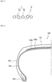
- FIG. 6 is a schematic half cross-sectional view illustrating a tire according to one preferred embodiment of the present invention.
- the illustrated pneumatic tire 100 includes: a tread portion 101 which forms a ground-contact part; a pair of side wall portions 102 which continuously extend inward in the tire radial direction on the respective sides of the tread portion 101; and bead portions 103 which continuously extend on the inner circumferential side of each side wall portion 102.
- the tread portion 101, the side wall portions 102 and the bead portions 103 are reinforced with a carcass 104, which is composed of a pair of carcass layers toroidally extending from one bead portion 103 to the other bead portion 103.
- the tread portion 101 is reinforced with a belt 105, which is composed of at least two layers (a first belt layer 105a and a second belt layer 105b in the illustrated example) that are arranged on the tire radial-direction outer side of the carcass 104 in a crown region.
- the carcass 104 may be composed of plural carcass layers, and an organic fiber cord extending in a direction substantially perpendicular to the tire circumferential direction, for example, at an angle of 70° to 90°, can be suitably used.
- the above-described elastomer-metal cord composite 10 of the present invention can be used in the first belt layer 105a and the second belt layer 105b.
- the elastomer-metal cord composite 10 of the present invention By using the elastomer-metal cord composite 10 of the present invention, the thickness of the steel cord of the first belt layer 105a and that of the second belt layer 105b can be reduced, so that the weight of the tire can be reduced.
- the elastomer-metal cord composite 10 of the present invention as a cord of the belt, the durability of the belt and the steering stability can both be improved at the same time.
- the tire 100 of the present invention may have any constitution as long as it includes the elastomer-metal cord composite 10 as claimed and other aspects of a specific tire structure are not particularly restricted.
- the part to which the elastomer-metal cord composite 10 of the present invention is applied is not restricted to the belt 105.
- the elastomer-metal cord composite 10 of the present invention may be used as a belt reinforcing layer arranged on the tire radial-direction outer side of the belt 105, or as other reinforcing member.
- an air having normal or adjusted oxygen partial pressure, as well as an inert gas such as nitrogen, argon or helium can be used as a gas filled into the tire 100.
Landscapes
- Engineering & Computer Science (AREA)
- Mechanical Engineering (AREA)
- Ropes Or Cables (AREA)
- Tires In General (AREA)
Description
- The present invention relates to an elastomer-metal cord composite and a tire. More particularly, the present invention relates to: an elastomer-metal cord composite obtained by coating, with an elastomer, a metal cord composed of a bundle of metal filaments that are parallelly aligned without being twisted together; and a tire including the same.
- In recent years, there is an increasing demand for weight reduction of tires for the purpose improving the fuel efficiency of automobiles. As means for reducing the tire weight, metal cords for belt reinforcement have been drawing attention, and a large number of techniques for using metal filaments as a belt cord without twisting have been disclosed. For example,
Patent Document 1 proposes a tire in which, for improvement of lightweightness and durability, a belt layer is constituted by at least two belt plies each obtained by arranging metal filament bundles along the width direction in a coating rubber, the metal filament bundles being formed by parallelly aligning small-diameter metal filaments at a high tensile strength without twisting. In this tire, the number of the metal filaments in each metal filament bundle is optimized in accordance with the metal filament diameter. Further, it is also proposed to adjust the thickness of the metal filament bundles in the radial direction to have a specific ratio with respect to the thickness of the belt plies. Attention is also drawn to the disclosures ofJP2000-198311A EP1256652A2 andJP2000-190707A - [Patent Document 1]
JP2001-334810A - However, in
Patent Document 1, although the lightweightness and the durability were examined, no examination was made on other performance. Therefore, in the use of metal filaments as a belt cord without twisting, there is expected to be a demand for further improvement as the tire performance is improved in the future. - In view of the above, an object of the present invention is to provide: an elastomer-metal cord composite capable of improving the performance of a tire, in which composite a metal cord composed of a bundle of metal filaments that are parallelly aligned without being twisted together is coated with an elastomer; and a tire including the same.
- The present inventor intensively studied to solve the above-described problems and obtained the following findings as a result. That is, the use of a metal cord obtained by bundling metal filaments without twisting them together suppresses in-plane deformation of the metal cord when a compressive input is made to a belt treat, and this leads to deterioration of the fatigue characteristics of the metal cord. In addition, in a metal cord obtained by bundling metal filaments without twisting them together, a rubber hardly infiltrates between adjacent metal filaments, and this causes the generation of a non-rubber-coated region where metal filaments are not coated with the rubber. Accordingly, the metal filaments are displaced from each other during tire rolling and, due to the resulting reduction in the in-plane rigidity, the steering stability may be impaired. Based on these findings, the present inventor further intensively studied and consequently discovered that the above-described problems can be solved by adopting the following constitution for a bundle of metal filaments, thereby completing the present invention.
- That is, the present invention provides an elastomer-metal cord composite as claimed in
claim 1. -
FIG. 1 is a drawing of a metal filament that describes the definitions of a patterning amount (h) and a patterning pitch (p) of the metal filament, and the "patterning amount (h)" refers to the width of undulation not including the wire diameter of ametal filament 1. The patterning amount (h) of themetal filament 1 is measured by projecting an image of the patternedmetal filament 1 on a screen or the like using a projector. - In the elastomer-metal cord composite of the present invention, it is preferred that a patterning direction of a patterned metal filament in the metal cord corresponds to a width direction of the metal cord. In the elastomer-metal cord composite of the present invention, it is also preferred that the adjacent metal filaments have an elastomer coating ratio of 10% or higher per unit length on a widthwise side surface of the metal cord. Further, in the elastomer-metal cord composite of the present invention, it is preferred that the straight metal filament and the patterned metal filament be alternately arranged. Still further, in the elastomer-metal cord composite of the present invention, it is preferred that the metal filaments have a patterning amount of 0.03 to 0.30 mm and a patterning pitch of 2 to 30 mm. It is noted here that, in the elastomer-metal cord composite of the present invention, the "straight metal filament" refers to a metal filament that is not intentionally patterned and is thus in a substantially unpatterned state.
- The term "elastomer coating ratio" used herein refers to, for example, when a rubber is used as the elastomer, a value calculated based on the following equation after coating the elastomer-metal cord composite of the present invention with the rubber, pulling out a steel cord from the resulting rubber-steel cord composite, and then measuring the length of a rubber-coated part of the steel cord:

- The elastomer coating ratio can be calculated in the same manner also when an elastomer other than a rubber is used as the elastomer.
- A tire of the present invention is characterized by including the elastomer-metal cord composite of the present invention.
- According to the present invention, an elastomer-metal cord composite capable of improving the performance of a tire, in which composite a metal cord composed of a bundle of metal filaments that are parallelly aligned without being twisted together is coated with an elastomer, and a tire including the same can be provided.
-
- [
FIG. 1] FIG. 1 is a drawing of a metal filament that describes the definitions of a patterning amount (h) and a patterning pitch (p) of the metal filament. - [
FIG. 2] FIG. 2 is a widthwise partial cross-sectional view illustrating an elastomer-metal cord composite according to one preferred embodiment of the present invention. - [
FIG. 3] FIG. 3 is a schematic plan view illustrating a metal cord of the elastomer-metal cord composite according to one preferred embodiment of the present invention. - [
FIG. 4] FIG. 4 is a schematic widthwise cross-sectional view illustrating the metal cord of the elastomer-metal cord composite according to one preferred embodiment of the present invention. - [
FIG. 5] FIG. 5 is a schematic widthwise cross-sectional view illustrating a metal cord of an elastomer-metal cord composite according to another preferred embodiment of the present invention. - [
FIG. 6] FIG. 6 is a schematic half cross-sectional view illustrating a tire according to one preferred embodiment of the present invention. - The elastomer-metal cord composite of the present invention will now be described in detail referring to the drawings.
FIG. 2 is a widthwise partial cross-sectional view illustrating an elastomer-metal cord composite according to one preferred embodiment of the present invention;FIG. 3 is a schematic plan view illustrating a metal cord of the elastomer-metal cord composite according to one preferred embodiment of the present invention;FIG. 4 is a schematic widthwise cross-sectional view illustrating the metal cord of the elastomer-metal cord composite according to one preferred embodiment of the present invention. An elastomer-metal cord composite 10 of the present invention is obtained by coating, with anelastomer 3, ametal cord 2 composed of a bundle of two to ten, preferably five to ninemetal filaments 1 that are parallelly aligned in a single row without being twisted together. In the illustrated example, fivemetal filaments 1 are parallelly aligned without being twisted together, forming themetal cord 2. - In the
metal cord 2 according to the elastomer-metal cord composite 10 of the present invention, there exists at least one pair ofadjacent metal filaments 1 that are different from each other in at least either of the patterning amount and the patterning pitch in a direction perpendicular to an extending direction of themetal filaments 1. Preferably, in 50% or more of such a pair, at least either of the patterning amount and the patterning pitch in the direction perpendicular to the extending direction of themetal filaments 1 is different between theadjacent metal filaments 1. In the illustrated example, patternedmetal filaments 1a andunpatterned metal filaments 1b (patterning amount = 0 mm, patterning pitch = ∞ mm) are alternately arranged; however, metal filaments having different patterning amounts may be alternately arranged, or metal filaments having different patterning pitches may be alternately arranged. With regard to the arrangement of the metal filaments constituting a bundle, it is preferred that both side portions be constituted by an unpatterned straight metal filament. In this manner, in the elastomer-metal cord composite 10 of the present invention, by adjacently arrangingmetal filaments 1 that are different in the patterning amount or the patterning pitch, theadjacent metal filaments 1 are prevented from having the same phase. By adopting this constitution, an elastomer is allowed to sufficiently infiltrate betweenadjacent metal filaments 1, as a result of which the steel cord can undergo out-of-plane deformation when a compressive input is applied thereto, and breakage of the steel cord can thereby be inhibited. - In addition, as described above, in a bundle of metal filaments, an elastomer hardly infiltrates between adjacent filaments, and this causes the generation of a non-elastomer-coated region where filaments are not coated with the elastomer. Accordingly, when a metal cord obtained by bundling metal filaments without twisting them together is used as a cord of a belt, the metal filaments in such a non-elastomer-coated region are displaced from each other during tire rolling, as a result of which the in-plane rigidity of the belt is reduced, and the steering stability may consequently be impaired. However, in the elastomer-
metal cord composite 10 of the present invention, since theelastomer 3 sufficiently infiltrates betweenadjacent metal filaments 1, the above-described defects can be eliminated and, by using the elastomer-metal cord composite 10 of the present invention as a cord of a belt, the in-plane rigidity of the belt can be enhanced and the steering stability can be improved. In order to favorably attain this effect,adjacent metal filaments 1 have an elastomer coating ratio per unit length of preferably 10% or higher, more preferably 20% or higher, on a widthwise side surface of themetal cord 2. Theadjacent metal filaments 1 are coated at a ratio of still more preferably 50% or higher, yet still more preferably 80% or higher, most preferably 90% or higher. - In the elastomer-
metal cord composite 10 of the present invention, an excessively large patterning amount of themetal filaments 1 makes a distance (w) between themetal cords 2 in the elastomer-metal cord composite 10 short, and this causes a reduction in the belt strength when the elastomer-metal cord composite 10 of the present invention is used as a belt. Accordingly, the patterning amount of themetal filaments 1 is preferably 0.03 to about 0.30 mm. When the patterning amount is greater than 0.30 mm, since the strength of the elastomer-metal cord composite is reduced, the effects of the present invention cannot be sufficiently attained. Particularly, from the standpoints of the distance (w) between themetal cords 2 and the strength of themetal filaments 1, when themetal filaments 1 are patterned, the patterning amount is preferably 0.03 to 0.30 mm, more preferably 0.03 to 0.25 mm, most preferably 0.03 to 0.20 mm. Further, the patterning pitch of themetal filaments 1 is preferably 2 to 30 mm, more preferably 2 to 20 mm, most preferably 3 to 15 mm. - In the
metal cord 2 illustrated inFIGs. 3 and 4 , the patternedmetal filaments 1a are patterned in the width direction of themetal cord 2; however, in the elastomer-metal cord composite 10 of the present invention, the patterning direction of themetal filaments 1a may be tilted with respect to the width direction of themetal cord 2.FIG. 5 is a schematic widthwise cross-sectional view illustrating a metal cord of an elastomer-metal cord composite according to another preferred embodiment of the present invention. Even in this structure, a rubber can sufficiently infiltrates betweenadjacent metal filaments 1, so that the effects of the invention can be attained. Nevertheless, in the elastomer-metal cord composite 10 of the present invention, from the standpoint of lightweightness, it is more preferred that the patterning direction ofadjacent metal filaments 1 be the width direction of themetal cord 2, since this can reduce the thickness of the elastomer-metal cord composite. - Moreover, in the elastomer-
metal cord composite 10 of the present invention, at least one of themetal filaments 1 in themetal cord 2 is a substantially straight metal filament. As illustrated inFIGs. 3 and 4 , when the unpatternedstraight metal filament 1b and the patternedmetal filament 1a are adjacent to each other, since the amount of the elastomer infiltrating between thesemetal filaments 1 is large, the elastomer coating ratio of theseadjacent metal filaments 1 on the widthwise side surface of themetal cord 2 is increased, so that the effects of the present invention can be favorably attained. In addition, by using straight metal filaments as themetal filaments 1 arranged on the respective ends of themetal cord 2, the durability can be improved since the distance (w) betweenadjacent metal cords 2 can be increased in the elastomer. More preferably, as illustrated inFIG. 2 , the unpatternedstraight metal filament 1b and the patternedmetal filament 1a are alternately arranged. - In the elastomer-
metal cord composite 10 of the present invention, the "metal filament 1" generally refers to a wire-like metal that contains steel, namely iron, as a main component (the mass of iron exceeds 50% by mass with respect to a total mass of the metal filament), and may be made of iron alone, or may contain a metal other than iron, such as zinc, copper, aluminum, or tin. - In the elastomer-
metal cord composite 10 of the present invention, the surface of themetal filament 1 may be treated by plating. The type of the plating is not particularly restricted, and examples thereof include zinc plating, copper plating, brass plating, and bronze plating. Thereamong, brass plating is preferred since a brass-plated metal filament exhibits excellent adhesion with rubber. In the brass plating, the ratio of copper and zinc (copper: zinc) is usually 60:40 to 70:30 based on mass. The thickness of the resulting plated layer is generally 100 nm to 300 nm. - In the elastomer-
metal cord composite 10 of the present invention, the wire diameter, the tensile strength and the cross-sectional shape of themetal filament 1 are not particularly restricted. For example, themetal filament 1 may have a wire diameter of 0.15 mm to 0.40 mm. As themetal filament 1, a metal filament having a tensile strength of 2,500 MPa or higher can be used. Further, the widthwise cross-sectional shape of themetal filament 1 is also not particularly restricted and may be, for example, elliptical, rectangular, triangular or polygonal; however, it is preferably circular. In the elastomer-metal cord composite 10 of the present invention, a wrapping filament may be used as well when it is necessary to restrain themetal filaments 1 constituting themetal cord 2. - Moreover, in the elastomer-
metal cord composite 10 of the present invention, theelastomer 3 coating themetal cord 2 is also not particularly restricted and, for example, any rubber that is conventionally used for coating a metal cord can be employed. In addition, examples of an elastomer that can be preferably used include diene-based rubbers and hydrogenation products thereof, such as natural rubbers (NR), isoprene rubbers (IR), epoxidized natural rubbers, styrene-butadiene rubbers (SBR), butadiene rubbers (BR, high-cis BR and low-cis BR), nitrile rubbers (NBR), hydrogenated NBRs, and hydrogenated SBRs; olefin-based rubbers, such as ethylene-propylene rubbers (EPDM and EPM), maleic acid-modified ethylene-propylene rubbers (M-EPM), butyl rubbers (IIR), copolymers of isobutylene and an aromatic vinyl or diene monomer, acrylic rubbers (ACM), and ionomers; halogen-containing rubbers, such as Br-IIR, Cl-IIR, brominated isobutylene-p-methylstyrene copolymers (Br-IPMS), chloroprene rubbers (CR), hydrin rubbers (CHR), chlorosulfonated polyethylene rubbers (CSM), chlorinated polyethylene rubbers (CM), and maleic acid-modified chlorinated polyethylene rubbers (M-CM); silicone rubbers, such as methyl vinyl silicone rubber, dimethyl silicone rubber, and methylphenyl vinyl silicone rubber; sulfur-containing rubbers, such as polysulfide rubbers; fluororubbers, such as vinylidene fluoride-based rubbers, fluorine-containing vinyl ether-based rubbers, tetrafluoroethylene-propylene-based rubbers, fluorine-containing silicone-based rubbers, and fluorine-containing phosphazene-based rubbers; and thermoplastic elastomers, such as styrene-based elastomers, olefin-based elastomers, ester-based elastomers, urethane-based elastomers, and polyamide-based elastomers. These elastomers may be used individually, or two or more thereof may be used in combination. Further, in these elastomers, an age inhibitor, zinc oxide, stearic acid and the like that are usually used in rubber products such as tires and conveyor bels may be incorporated as appropriate, in addition to sulfur, a vulcanization accelerator and carbon black. - The elastomer-metal cord composite of the present invention can be produced by any known method. For example, the elastomer-metal cord composite of the present invention can be produced by parallelly arranging the metal cords according to the present invention at prescribed intervals and subsequently coating the thus arranged metal cords from both above and below with an about 0.5-mm thick sheet made of an elastomer. Further, patterning of the metal filaments can be performed by any conventional method using an ordinary patterning machine.
- The tire of the present invention will now be described.
- A
tire 100 of the present invention includes the elastomer-metal cord composite 10 of the present invention, and examples of thetire 100 include tires for passenger vehicles and tires for trucks and buses.FIG. 6 is a schematic half cross-sectional view illustrating a tire according to one preferred embodiment of the present invention. The illustratedpneumatic tire 100 includes: atread portion 101 which forms a ground-contact part; a pair ofside wall portions 102 which continuously extend inward in the tire radial direction on the respective sides of thetread portion 101; andbead portions 103 which continuously extend on the inner circumferential side of eachside wall portion 102. - In the illustrated
tire 100, thetread portion 101, theside wall portions 102 and thebead portions 103 are reinforced with acarcass 104, which is composed of a pair of carcass layers toroidally extending from onebead portion 103 to theother bead portion 103. In addition, thetread portion 101 is reinforced with a belt 105, which is composed of at least two layers (afirst belt layer 105a and asecond belt layer 105b in the illustrated example) that are arranged on the tire radial-direction outer side of thecarcass 104 in a crown region. It is noted here that thecarcass 104 may be composed of plural carcass layers, and an organic fiber cord extending in a direction substantially perpendicular to the tire circumferential direction, for example, at an angle of 70° to 90°, can be suitably used. - In the
tire 100 of the present invention, the above-described elastomer-metal cord composite 10 of the present invention can be used in thefirst belt layer 105a and thesecond belt layer 105b. By using the elastomer-metal cord composite 10 of the present invention, the thickness of the steel cord of thefirst belt layer 105a and that of thesecond belt layer 105b can be reduced, so that the weight of the tire can be reduced. Moreover, by using the elastomer-metal cord composite 10 of the present invention as a cord of the belt, the durability of the belt and the steering stability can both be improved at the same time. - The
tire 100 of the present invention may have any constitution as long as it includes the elastomer-metal cord composite 10 as claimed and other aspects of a specific tire structure are not particularly restricted. In addition, the part to which the elastomer-metal cord composite 10 of the present invention is applied is not restricted to the belt 105. For example, the elastomer-metal cord composite 10 of the present invention may be used as a belt reinforcing layer arranged on the tire radial-direction outer side of the belt 105, or as other reinforcing member. As a gas filled into thetire 100, an air having normal or adjusted oxygen partial pressure, as well as an inert gas such as nitrogen, argon or helium, can be used. -
- 1:
- metal filament
- 2:
- metal cord
- 3:
- elastomer
- 10:
- elastomer-metal cord composite
- 100:
- tire (pneumatic tire)
- 101:
- tread portion
- 102:
- side wall portion
- 103:
- bead portion
- 104:
- carcass
- 105:
- belt layer
Claims (6)
- An elastomer-metal cord composite (10) obtained by coating, with an elastomer (3), a metal cord (2) composed of a bundle of two to ten metal filaments (1) that are parallelly aligned in a single row without being twisted together,wherein the metal cord (2) comprises at least one pair of adjacent metal filaments (1) being different from each other in at least either of patterning amount (h) and patterning pitch (p) in a direction perpendicular to an extending direction of the metal filaments (1),wherein at least one of the metal filaments (1) in the metal cord (2) is a substantially straight metal filament (1b), andwherein metal filaments (1) arranged on the respective ends of the metal cord (2) are each the straight metal filament (1b).
- The elastomer-metal cord composite (10) according to claim 1, wherein a patterning direction of a patterned metal filament (1a) in the metal cord (2) corresponds to a width direction of the metal cord (2).
- The elastomer-metal cord composite (10) according to claim 1 or 2, wherein the adjacent metal filaments (1) have an elastomer coating ratio of 10% or higher per 50 mm on a widthwise side surface of the metal cord (2).
- The elastomer-metal cord composite (10) according to any one of claims 1 to 3, wherein the straight metal filament (1b) and the patterned metal filament (1a) are alternately arranged.
- The elastomer-metal cord composite (10) according to any one of claims 1 to 4, wherein the metal filaments (1) have a patterning amount (h) of 0.03 to 0.30 mm and a patterning pitch (p) of 2 to 30 mm.
- A tire comprising the elastomer-metal cord composite (10) according to any one of claims 1 to 5.
Applications Claiming Priority (2)
| Application Number | Priority Date | Filing Date | Title |
|---|---|---|---|
| JP2017078439 | 2017-04-11 | ||
| PCT/JP2018/014965 WO2018190308A1 (en) | 2017-04-11 | 2018-04-09 | Elastomer-metal cord composite and tire using same |
Publications (3)
| Publication Number | Publication Date |
|---|---|
| EP3611035A1 EP3611035A1 (en) | 2020-02-19 |
| EP3611035A4 EP3611035A4 (en) | 2020-11-25 |
| EP3611035B1 true EP3611035B1 (en) | 2022-03-16 |
Family
ID=63793279
Family Applications (1)
| Application Number | Title | Priority Date | Filing Date |
|---|---|---|---|
| EP18785148.0A Active EP3611035B1 (en) | 2017-04-11 | 2018-04-09 | Elastomer-metal cord composite and tire using same |
Country Status (5)
| Country | Link |
|---|---|
| US (1) | US20200039295A1 (en) |
| EP (1) | EP3611035B1 (en) |
| JP (1) | JP7073345B2 (en) |
| CN (1) | CN110494302A (en) |
| WO (1) | WO2018190308A1 (en) |
Families Citing this family (6)
| Publication number | Priority date | Publication date | Assignee | Title |
|---|---|---|---|---|
| JPWO2020080442A1 (en) * | 2018-10-17 | 2021-10-07 | 株式会社ブリヂストン | Elastomer-metal cord complex and tires using it |
| WO2020080439A1 (en) * | 2018-10-17 | 2020-04-23 | 株式会社ブリヂストン | Tire |
| WO2020080440A1 (en) * | 2018-10-17 | 2020-04-23 | 株式会社ブリヂストン | Elastomer-metal cord composite body and tire using same |
| JP7199311B2 (en) * | 2019-06-19 | 2023-01-05 | 株式会社ブリヂストン | pneumatic tire |
| JP7312100B2 (en) * | 2019-12-13 | 2023-07-20 | 株式会社ブリヂストン | tire |
| WO2023095471A1 (en) * | 2021-11-24 | 2023-06-01 | 株式会社ブリヂストン | Tire |
Family Cites Families (15)
| Publication number | Priority date | Publication date | Assignee | Title |
|---|---|---|---|---|
| JPS5235784B2 (en) * | 1973-04-26 | 1977-09-10 | ||
| JPH06235179A (en) * | 1993-02-09 | 1994-08-23 | Kokoku Kousensaku Kk | Steel cord and composite rubber material using the steel cord |
| JP2995525B2 (en) * | 1993-11-22 | 1999-12-27 | 東京製綱株式会社 | Shaped wire convergence code and vehicle tire |
| JPH07157986A (en) * | 1993-12-02 | 1995-06-20 | Tokyo Seiko Co Ltd | Shaped wire convergence code and vehicle tire |
| JP3403545B2 (en) * | 1995-05-01 | 2003-05-06 | 横浜ゴム株式会社 | Pneumatic radial tire |
| JPH0913288A (en) * | 1995-06-22 | 1997-01-14 | Bridgestone Corp | Steel cord for reinforcing rubber article and pneumatic radial tire |
| JPH0913299A (en) * | 1995-06-26 | 1997-01-14 | Kobe Steel Ltd | Production of heat-insulating cushioning material by using defibrated waste paper pulp as raw material |
| JP2000129583A (en) * | 1998-10-16 | 2000-05-09 | Yokohama Rubber Co Ltd:The | Steel cord and pneumatic tire using the same |
| JP3837249B2 (en) * | 1998-12-25 | 2006-10-25 | 横浜ゴム株式会社 | Pneumatic radial tire for passenger cars |
| JP2000198311A (en) * | 1999-01-06 | 2000-07-18 | Toyo Tire & Rubber Co Ltd | Tire reinforcement and pneumatic tires |
| JP4132522B2 (en) * | 1999-12-27 | 2008-08-13 | 住友ゴム工業株式会社 | Pneumatic radial tire |
| JP2001334810A (en) | 2000-05-29 | 2001-12-04 | Bridgestone Corp | Pneumatic radial tire |
| JP4392139B2 (en) * | 2001-05-09 | 2009-12-24 | 住友ゴム工業株式会社 | Metal cord and pneumatic tire using the same |
| JP4842117B2 (en) * | 2006-12-26 | 2011-12-21 | 株式会社ブリヂストン | Pneumatic tire |
| EP2123483B1 (en) * | 2006-12-26 | 2017-06-07 | Bridgestone Corporation | Pneumatic tire |
-
2018
- 2018-04-09 CN CN201880024598.4A patent/CN110494302A/en active Pending
- 2018-04-09 EP EP18785148.0A patent/EP3611035B1/en active Active
- 2018-04-09 WO PCT/JP2018/014965 patent/WO2018190308A1/en not_active Ceased
- 2018-04-09 JP JP2019512503A patent/JP7073345B2/en active Active
-
2019
- 2019-10-10 US US16/597,932 patent/US20200039295A1/en not_active Abandoned
Also Published As
| Publication number | Publication date |
|---|---|
| EP3611035A1 (en) | 2020-02-19 |
| JP7073345B2 (en) | 2022-05-23 |
| CN110494302A (en) | 2019-11-22 |
| WO2018190308A1 (en) | 2018-10-18 |
| JPWO2018190308A1 (en) | 2020-02-27 |
| EP3611035A4 (en) | 2020-11-25 |
| US20200039295A1 (en) | 2020-02-06 |
Similar Documents
| Publication | Publication Date | Title |
|---|---|---|
| EP3611035B1 (en) | Elastomer-metal cord composite and tire using same | |
| US20200039294A1 (en) | Elastomer-metal cord composite and tire using same | |
| US20210354515A1 (en) | Tire | |
| US11833867B2 (en) | Tire | |
| JP2021094916A (en) | tire | |
| JP2018176960A (en) | Elastomer-metal cord composite, and tire | |
| EP3868575B1 (en) | Elastomer-metal cord composite body, and tire using same | |
| US12128711B2 (en) | Pneumatic tire | |
| JP7351846B2 (en) | Elastomer-metal cord composite and tires using the same | |
| JP7397656B2 (en) | tire | |
| EP4681940A1 (en) | Tire | |
| JP2020062968A (en) | tire | |
| JPWO2020080445A1 (en) | tire | |
| JPWO2020080440A1 (en) | Elastomer-metal cord complex and tires using it | |
| WO2020080446A1 (en) | Tire | |
| JP2020062970A (en) | tire | |
| JP2019217918A (en) | Pneumatic tire | |
| JP2000225809A (en) | Pneumatic radial tire for passenger car |
Legal Events
| Date | Code | Title | Description |
|---|---|---|---|
| STAA | Information on the status of an ep patent application or granted ep patent |
Free format text: STATUS: THE INTERNATIONAL PUBLICATION HAS BEEN MADE |
|
| PUAI | Public reference made under article 153(3) epc to a published international application that has entered the european phase |
Free format text: ORIGINAL CODE: 0009012 |
|
| STAA | Information on the status of an ep patent application or granted ep patent |
Free format text: STATUS: REQUEST FOR EXAMINATION WAS MADE |
|
| 17P | Request for examination filed |
Effective date: 20191111 |
|
| AK | Designated contracting states |
Kind code of ref document: A1 Designated state(s): AL AT BE BG CH CY CZ DE DK EE ES FI FR GB GR HR HU IE IS IT LI LT LU LV MC MK MT NL NO PL PT RO RS SE SI SK SM TR |
|
| AX | Request for extension of the european patent |
Extension state: BA ME |
|
| DAV | Request for validation of the european patent (deleted) | ||
| DAX | Request for extension of the european patent (deleted) | ||
| A4 | Supplementary search report drawn up and despatched |
Effective date: 20201022 |
|
| RIC1 | Information provided on ipc code assigned before grant |
Ipc: B60C 9/20 20060101ALI20201016BHEP Ipc: D07B 1/06 20060101ALI20201016BHEP Ipc: B60C 9/00 20060101AFI20201016BHEP |
|
| GRAP | Despatch of communication of intention to grant a patent |
Free format text: ORIGINAL CODE: EPIDOSNIGR1 |
|
| STAA | Information on the status of an ep patent application or granted ep patent |
Free format text: STATUS: GRANT OF PATENT IS INTENDED |
|
| INTG | Intention to grant announced |
Effective date: 20211129 |
|
| GRAS | Grant fee paid |
Free format text: ORIGINAL CODE: EPIDOSNIGR3 |
|
| GRAA | (expected) grant |
Free format text: ORIGINAL CODE: 0009210 |
|
| STAA | Information on the status of an ep patent application or granted ep patent |
Free format text: STATUS: THE PATENT HAS BEEN GRANTED |
|
| AK | Designated contracting states |
Kind code of ref document: B1 Designated state(s): AL AT BE BG CH CY CZ DE DK EE ES FI FR GB GR HR HU IE IS IT LI LT LU LV MC MK MT NL NO PL PT RO RS SE SI SK SM TR |
|
| REG | Reference to a national code |
Ref country code: GB Ref legal event code: FG4D |
|
| REG | Reference to a national code |
Ref country code: CH Ref legal event code: EP |
|
| REG | Reference to a national code |
Ref country code: DE Ref legal event code: R096 Ref document number: 602018032394 Country of ref document: DE |
|
| REG | Reference to a national code |
Ref country code: IE Ref legal event code: FG4D |
|
| REG | Reference to a national code |
Ref country code: AT Ref legal event code: REF Ref document number: 1475632 Country of ref document: AT Kind code of ref document: T Effective date: 20220415 |
|
| REG | Reference to a national code |
Ref country code: LT Ref legal event code: MG9D |
|
| REG | Reference to a national code |
Ref country code: NL Ref legal event code: MP Effective date: 20220316 |
|
| PG25 | Lapsed in a contracting state [announced via postgrant information from national office to epo] |
Ref country code: SE Free format text: LAPSE BECAUSE OF FAILURE TO SUBMIT A TRANSLATION OF THE DESCRIPTION OR TO PAY THE FEE WITHIN THE PRESCRIBED TIME-LIMIT Effective date: 20220316 Ref country code: RS Free format text: LAPSE BECAUSE OF FAILURE TO SUBMIT A TRANSLATION OF THE DESCRIPTION OR TO PAY THE FEE WITHIN THE PRESCRIBED TIME-LIMIT Effective date: 20220316 Ref country code: NO Free format text: LAPSE BECAUSE OF FAILURE TO SUBMIT A TRANSLATION OF THE DESCRIPTION OR TO PAY THE FEE WITHIN THE PRESCRIBED TIME-LIMIT Effective date: 20220616 Ref country code: LT Free format text: LAPSE BECAUSE OF FAILURE TO SUBMIT A TRANSLATION OF THE DESCRIPTION OR TO PAY THE FEE WITHIN THE PRESCRIBED TIME-LIMIT Effective date: 20220316 Ref country code: HR Free format text: LAPSE BECAUSE OF FAILURE TO SUBMIT A TRANSLATION OF THE DESCRIPTION OR TO PAY THE FEE WITHIN THE PRESCRIBED TIME-LIMIT Effective date: 20220316 Ref country code: BG Free format text: LAPSE BECAUSE OF FAILURE TO SUBMIT A TRANSLATION OF THE DESCRIPTION OR TO PAY THE FEE WITHIN THE PRESCRIBED TIME-LIMIT Effective date: 20220616 |
|
| REG | Reference to a national code |
Ref country code: AT Ref legal event code: MK05 Ref document number: 1475632 Country of ref document: AT Kind code of ref document: T Effective date: 20220316 |
|
| PG25 | Lapsed in a contracting state [announced via postgrant information from national office to epo] |
Ref country code: LV Free format text: LAPSE BECAUSE OF FAILURE TO SUBMIT A TRANSLATION OF THE DESCRIPTION OR TO PAY THE FEE WITHIN THE PRESCRIBED TIME-LIMIT Effective date: 20220316 Ref country code: GR Free format text: LAPSE BECAUSE OF FAILURE TO SUBMIT A TRANSLATION OF THE DESCRIPTION OR TO PAY THE FEE WITHIN THE PRESCRIBED TIME-LIMIT Effective date: 20220617 Ref country code: FI Free format text: LAPSE BECAUSE OF FAILURE TO SUBMIT A TRANSLATION OF THE DESCRIPTION OR TO PAY THE FEE WITHIN THE PRESCRIBED TIME-LIMIT Effective date: 20220316 |
|
| PG25 | Lapsed in a contracting state [announced via postgrant information from national office to epo] |
Ref country code: NL Free format text: LAPSE BECAUSE OF FAILURE TO SUBMIT A TRANSLATION OF THE DESCRIPTION OR TO PAY THE FEE WITHIN THE PRESCRIBED TIME-LIMIT Effective date: 20220316 |
|
| PG25 | Lapsed in a contracting state [announced via postgrant information from national office to epo] |
Ref country code: SM Free format text: LAPSE BECAUSE OF FAILURE TO SUBMIT A TRANSLATION OF THE DESCRIPTION OR TO PAY THE FEE WITHIN THE PRESCRIBED TIME-LIMIT Effective date: 20220316 Ref country code: SK Free format text: LAPSE BECAUSE OF FAILURE TO SUBMIT A TRANSLATION OF THE DESCRIPTION OR TO PAY THE FEE WITHIN THE PRESCRIBED TIME-LIMIT Effective date: 20220316 Ref country code: RO Free format text: LAPSE BECAUSE OF FAILURE TO SUBMIT A TRANSLATION OF THE DESCRIPTION OR TO PAY THE FEE WITHIN THE PRESCRIBED TIME-LIMIT Effective date: 20220316 Ref country code: PT Free format text: LAPSE BECAUSE OF FAILURE TO SUBMIT A TRANSLATION OF THE DESCRIPTION OR TO PAY THE FEE WITHIN THE PRESCRIBED TIME-LIMIT Effective date: 20220718 Ref country code: ES Free format text: LAPSE BECAUSE OF FAILURE TO SUBMIT A TRANSLATION OF THE DESCRIPTION OR TO PAY THE FEE WITHIN THE PRESCRIBED TIME-LIMIT Effective date: 20220316 Ref country code: EE Free format text: LAPSE BECAUSE OF FAILURE TO SUBMIT A TRANSLATION OF THE DESCRIPTION OR TO PAY THE FEE WITHIN THE PRESCRIBED TIME-LIMIT Effective date: 20220316 Ref country code: CZ Free format text: LAPSE BECAUSE OF FAILURE TO SUBMIT A TRANSLATION OF THE DESCRIPTION OR TO PAY THE FEE WITHIN THE PRESCRIBED TIME-LIMIT Effective date: 20220316 Ref country code: AT Free format text: LAPSE BECAUSE OF FAILURE TO SUBMIT A TRANSLATION OF THE DESCRIPTION OR TO PAY THE FEE WITHIN THE PRESCRIBED TIME-LIMIT Effective date: 20220316 |
|
| PG25 | Lapsed in a contracting state [announced via postgrant information from national office to epo] |
Ref country code: PL Free format text: LAPSE BECAUSE OF FAILURE TO SUBMIT A TRANSLATION OF THE DESCRIPTION OR TO PAY THE FEE WITHIN THE PRESCRIBED TIME-LIMIT Effective date: 20220316 Ref country code: IS Free format text: LAPSE BECAUSE OF FAILURE TO SUBMIT A TRANSLATION OF THE DESCRIPTION OR TO PAY THE FEE WITHIN THE PRESCRIBED TIME-LIMIT Effective date: 20220716 Ref country code: AL Free format text: LAPSE BECAUSE OF FAILURE TO SUBMIT A TRANSLATION OF THE DESCRIPTION OR TO PAY THE FEE WITHIN THE PRESCRIBED TIME-LIMIT Effective date: 20220316 |
|
| REG | Reference to a national code |
Ref country code: CH Ref legal event code: PL |
|
| REG | Reference to a national code |
Ref country code: DE Ref legal event code: R097 Ref document number: 602018032394 Country of ref document: DE |
|
| REG | Reference to a national code |
Ref country code: BE Ref legal event code: MM Effective date: 20220430 |
|
| PLBE | No opposition filed within time limit |
Free format text: ORIGINAL CODE: 0009261 |
|
| STAA | Information on the status of an ep patent application or granted ep patent |
Free format text: STATUS: NO OPPOSITION FILED WITHIN TIME LIMIT |
|
| PG25 | Lapsed in a contracting state [announced via postgrant information from national office to epo] |
Ref country code: MC Free format text: LAPSE BECAUSE OF FAILURE TO SUBMIT A TRANSLATION OF THE DESCRIPTION OR TO PAY THE FEE WITHIN THE PRESCRIBED TIME-LIMIT Effective date: 20220316 Ref country code: LU Free format text: LAPSE BECAUSE OF NON-PAYMENT OF DUE FEES Effective date: 20220409 Ref country code: LI Free format text: LAPSE BECAUSE OF NON-PAYMENT OF DUE FEES Effective date: 20220430 Ref country code: DK Free format text: LAPSE BECAUSE OF FAILURE TO SUBMIT A TRANSLATION OF THE DESCRIPTION OR TO PAY THE FEE WITHIN THE PRESCRIBED TIME-LIMIT Effective date: 20220316 Ref country code: CH Free format text: LAPSE BECAUSE OF NON-PAYMENT OF DUE FEES Effective date: 20220430 |
|
| 26N | No opposition filed |
Effective date: 20221219 |
|
| PG25 | Lapsed in a contracting state [announced via postgrant information from national office to epo] |
Ref country code: SI Free format text: LAPSE BECAUSE OF FAILURE TO SUBMIT A TRANSLATION OF THE DESCRIPTION OR TO PAY THE FEE WITHIN THE PRESCRIBED TIME-LIMIT Effective date: 20220316 Ref country code: BE Free format text: LAPSE BECAUSE OF NON-PAYMENT OF DUE FEES Effective date: 20220430 |
|
| GBPC | Gb: european patent ceased through non-payment of renewal fee |
Effective date: 20220616 |
|
| PG25 | Lapsed in a contracting state [announced via postgrant information from national office to epo] |
Ref country code: IE Free format text: LAPSE BECAUSE OF NON-PAYMENT OF DUE FEES Effective date: 20220409 |
|
| PG25 | Lapsed in a contracting state [announced via postgrant information from national office to epo] |
Ref country code: GB Free format text: LAPSE BECAUSE OF NON-PAYMENT OF DUE FEES Effective date: 20220616 |
|
| P01 | Opt-out of the competence of the unified patent court (upc) registered |
Effective date: 20230531 |
|
| PG25 | Lapsed in a contracting state [announced via postgrant information from national office to epo] |
Ref country code: IT Free format text: LAPSE BECAUSE OF FAILURE TO SUBMIT A TRANSLATION OF THE DESCRIPTION OR TO PAY THE FEE WITHIN THE PRESCRIBED TIME-LIMIT Effective date: 20220316 |
|
| PG25 | Lapsed in a contracting state [announced via postgrant information from national office to epo] |
Ref country code: MK Free format text: LAPSE BECAUSE OF FAILURE TO SUBMIT A TRANSLATION OF THE DESCRIPTION OR TO PAY THE FEE WITHIN THE PRESCRIBED TIME-LIMIT Effective date: 20220316 Ref country code: CY Free format text: LAPSE BECAUSE OF FAILURE TO SUBMIT A TRANSLATION OF THE DESCRIPTION OR TO PAY THE FEE WITHIN THE PRESCRIBED TIME-LIMIT Effective date: 20220316 |
|
| PG25 | Lapsed in a contracting state [announced via postgrant information from national office to epo] |
Ref country code: HU Free format text: LAPSE BECAUSE OF FAILURE TO SUBMIT A TRANSLATION OF THE DESCRIPTION OR TO PAY THE FEE WITHIN THE PRESCRIBED TIME-LIMIT; INVALID AB INITIO Effective date: 20180409 |
|
| PG25 | Lapsed in a contracting state [announced via postgrant information from national office to epo] |
Ref country code: TR Free format text: LAPSE BECAUSE OF FAILURE TO SUBMIT A TRANSLATION OF THE DESCRIPTION OR TO PAY THE FEE WITHIN THE PRESCRIBED TIME-LIMIT Effective date: 20220316 |
|
| PG25 | Lapsed in a contracting state [announced via postgrant information from national office to epo] |
Ref country code: MT Free format text: LAPSE BECAUSE OF FAILURE TO SUBMIT A TRANSLATION OF THE DESCRIPTION OR TO PAY THE FEE WITHIN THE PRESCRIBED TIME-LIMIT Effective date: 20220316 |
|
| PGFP | Annual fee paid to national office [announced via postgrant information from national office to epo] |
Ref country code: DE Payment date: 20250422 Year of fee payment: 8 |
|
| PGFP | Annual fee paid to national office [announced via postgrant information from national office to epo] |
Ref country code: FR Payment date: 20250425 Year of fee payment: 8 |