EP3610769B1 - Self-squeezing mop having foamed cotton head and enabling convenient squeezing operation - Google Patents
Self-squeezing mop having foamed cotton head and enabling convenient squeezing operation Download PDFInfo
- Publication number
- EP3610769B1 EP3610769B1 EP18818432.9A EP18818432A EP3610769B1 EP 3610769 B1 EP3610769 B1 EP 3610769B1 EP 18818432 A EP18818432 A EP 18818432A EP 3610769 B1 EP3610769 B1 EP 3610769B1
- Authority
- EP
- European Patent Office
- Prior art keywords
- foam cotton
- cotton head
- wringing
- squeezing
- wringing frame
- Prior art date
- Legal status (The legal status is an assumption and is not a legal conclusion. Google has not performed a legal analysis and makes no representation as to the accuracy of the status listed.)
- Active
Links
Images






Classifications
-
- A—HUMAN NECESSITIES
- A47—FURNITURE; DOMESTIC ARTICLES OR APPLIANCES; COFFEE MILLS; SPICE MILLS; SUCTION CLEANERS IN GENERAL
- A47L—DOMESTIC WASHING OR CLEANING; SUCTION CLEANERS IN GENERAL
- A47L13/00—Implements for cleaning floors, carpets, furniture, walls, or wall coverings
- A47L13/10—Scrubbing; Scouring; Cleaning; Polishing
- A47L13/14—Scrubbing; Scouring; Cleaning; Polishing combined with squeezing or wringing devices
- A47L13/144—Scrubbing; Scouring; Cleaning; Polishing combined with squeezing or wringing devices having squeezing rollers
-
- A—HUMAN NECESSITIES
- A47—FURNITURE; DOMESTIC ARTICLES OR APPLIANCES; COFFEE MILLS; SPICE MILLS; SUCTION CLEANERS IN GENERAL
- A47L—DOMESTIC WASHING OR CLEANING; SUCTION CLEANERS IN GENERAL
- A47L13/00—Implements for cleaning floors, carpets, furniture, walls, or wall coverings
- A47L13/10—Scrubbing; Scouring; Cleaning; Polishing
- A47L13/20—Mops
- A47L13/24—Frames for mops; Mop heads
-
- A—HUMAN NECESSITIES
- A47—FURNITURE; DOMESTIC ARTICLES OR APPLIANCES; COFFEE MILLS; SPICE MILLS; SUCTION CLEANERS IN GENERAL
- A47L—DOMESTIC WASHING OR CLEANING; SUCTION CLEANERS IN GENERAL
- A47L13/00—Implements for cleaning floors, carpets, furniture, walls, or wall coverings
- A47L13/10—Scrubbing; Scouring; Cleaning; Polishing
- A47L13/20—Mops
- A47L13/24—Frames for mops; Mop heads
- A47L13/254—Plate frames
- A47L13/257—Plate frames for mops made of sponge material
-
- A—HUMAN NECESSITIES
- A47—FURNITURE; DOMESTIC ARTICLES OR APPLIANCES; COFFEE MILLS; SPICE MILLS; SUCTION CLEANERS IN GENERAL
- A47L—DOMESTIC WASHING OR CLEANING; SUCTION CLEANERS IN GENERAL
- A47L13/00—Implements for cleaning floors, carpets, furniture, walls, or wall coverings
- A47L13/10—Scrubbing; Scouring; Cleaning; Polishing
- A47L13/14—Scrubbing; Scouring; Cleaning; Polishing combined with squeezing or wringing devices
- A47L13/146—Scrubbing; Scouring; Cleaning; Polishing combined with squeezing or wringing devices having pivoting squeezing plates
-
- A—HUMAN NECESSITIES
- A47—FURNITURE; DOMESTIC ARTICLES OR APPLIANCES; COFFEE MILLS; SPICE MILLS; SUCTION CLEANERS IN GENERAL
- A47L—DOMESTIC WASHING OR CLEANING; SUCTION CLEANERS IN GENERAL
- A47L13/00—Implements for cleaning floors, carpets, furniture, walls, or wall coverings
- A47L13/10—Scrubbing; Scouring; Cleaning; Polishing
- A47L13/16—Cloths; Pads; Sponges
Definitions
- the present invention relates to a foam cotton mop, and in particular to a self-wringing foam cotton mop with a labor-saving wringing operation, wherein the foam cotton can be collodion, sponge or the like.
- collodion mops available in the market are roughly the same in structure.
- Such a collodion mop includes a mop rod, a mop head and a wringing mechanism.
- the wringing device in the collodion mop is a transmission structure.
- the wringing device includes a handle, a pull rod, a caliper seat (a wringing frame), a collodion clamp and a wringing bar.
- the caliper seat is roughly U-shaped.
- a collodion head is clamped by the collodion clamp, and the collodion clamp is fixed at the bottom end of the pull rod.
- the top end of the pull rod is movably pin-connected to a middle portion of the handle, and the rear end of the handle is pin-connected to the mop rod.
- the wringing bar is oblate, and two ends of the wringing bar are pin-connected to a lower end of the caliper seat.
- Chinese Patents such as CN2626415Y entitled COLLODION MOP, CN201409887Y entitled INSERTION-TYPE WRINGING COLLODION MOP, CN201453183U entitled COLLODION MOP and CN102138771A entitled MOVABLE MULTIFUNCTIONAL COLLODION MOP, disclosed wringing devices for collodion mops.
- US5172446A discloses a self-wringing mop where a mop cloth is pulled away from the mop head and up into a wringer device.
- the handle is pulled to drive the collodion head to horizontally move up through the pull rod, and the collodion head passes through the wringing bar of the wringing frame. Due to certain elasticity of the wringing frame, the wringing bar has an elastic force for keeping a clamping trend, so the collodion head passing through the wringing bar will be squeezed by the wringing bar so as to realize the wringing operation.
- This wringing approach of the collodion mop has become an inertial thinking for designers, and this wringing approach has the following deficiencies.
- the wringing operation is performed by moving the wringing frame in the height direction of the collodion mop.
- the transverse length of the wringing bar In order to enable the whole collodion mop to be squeezed by the wringing bar, the transverse length of the wringing bar must approach to the length of the collodion mop. In this way, the wringing part is large in overall transverse length and relatively heavy.
- the material consumption is large, and the contact area of the wringing bars with the collodion head is very large during the wringing process, so that the friction during the wringing operation is greatly increased and the wringing frame is high in cost.
- the collodion head and the mop rod must be fixedly connected to each other, and the collodion head cannot be completely separated from the wringing frame, that is, the collodion head cannot be rotated relative to the mop rod.
- a technical problem to be solved by the present invention is to provide a self-wringing foam cotton mop with a labor-saving wringing operation which changes the wringing mode of the conventional collodion mops.
- the mop can ensure excellent wringing effect and labor-saving wringing operation.
- the present invention provides a self-wringing foam cotton mop with a labor-saving wringing operation, comprising a mop rod and a foam cotton head, wherein the foam cotton head is rotatably connected to a bottom end of the mop rod; a wringing frame is disposed on the mop rod; during mopping, the foam cotton head is separated from the wringing frame; a squeezing mechanism capable of squeezing the foam cotton head entering the wringing frame is disposed on the wringing frame; a position of the squeezing mechanism is changeable, so that the position of the squeezing mechanism when the foam cotton head is moved upward relative to the wringing frame is different from the position of the squeezing mechanism when the foam cotton head is moved downward relative to the wringing frame; therefore, a first amount of deformation generated by the foam cotton head during an upward movement of the foam cotton head relative to the wringing frame is
- the foam cotton head is rotated to allow the end face to be aligned with the through hole.
- the squeezing mechanism that does not swing enables the foam cotton head to generate the first amount of deformation; and, in the process that the foam cotton head enters the through hole and moves down, the swung squeezing mechanism enables the foam cotton head to generate the second amount of deformation.
- the changeable position of the squeezing mechanism is realized by swinging the squeezing mechanism.
- the squeezing mechanism that does not swing is always kept in a state of gradually inclining towards the bottom surface of the foam cotton head from the bottom up, so that the squeezing passage is a passage with a larger bottom and a smaller top, and it is advantageous for allowing the foam cotton head to enter the through hole.
- the squeezing force gradually increases, the foam cotton head can be better dewatered, and the wringing operation is labor-saving.
- the swung squeezing mechanism enables the foam cotton head will deflect to allow the upper end of the squeezing mechanism to move away from the bottom surface of the foam cotton head, so that the entrance at the upper end becomes larger.
- the wringing operation is further labor-saving.
- the squeezing mechanism may include a squeezing plate and a connecting plate.
- the squeezing plate is adapted to be in contact with the bottom surface of the foam cotton head, and the squeezing plate is rotatably constrained on the wringing frame and is movable up and down within a certain range in an axial direction of the wringing frame.
- One end of the connecting plate is rotatably connected to the writing frame, while the other end of the connecting plate is hinged to an upper end of the squeezing plate.
- An elastic member for allowing a lower end of the connecting plate to keep in a trend of deflecting close to the bottom surface of the foam cotton head and a limiting structure for limiting an upward movement of the connecting plate are provided on the wringing frame.
- the squeezing plate can come into contact with the bottom surface of the foam cotton head through a wringing roller that is rotatably provided on the squeezing plate.
- a preferred scheme of the squeezing mechanism has been shown above.
- the limiting structure prevents the connecting plate from further moving up, so that the connecting plate can be kept at the inclined position.
- the foam cotton head acts on the connecting plate so that the connecting plate is pulled downward to drive the squeezing plate to move down.
- the upper end of the connecting plate deflects to move away from the bottom surface of the foam cotton head, so that the entrance at the upper end becomes larger and it is advantageous for allowing the foam cotton head to downward passing through the through hole.
- Arc-shaped guide grooves may be formed on left and right inner sidewalls of the through hole, and guide columns inserted into the guide grooves are provided in a middle portion of left and right sides of the squeezing plate.
- the squeezing mechanism may include a squeezing plate, and a wringing roller for coming into contact with the bottom surface of the foam cotton head; one end of the squeezing plate is hinged to the wringing frame; an elastic member for allowing an upper end of the squeezing plate to keep in a trend of deflecting close to the bottom surface of the foam cotton head is disposed on the writing frame, and a limiting portion for limiting the rotation position of the squeezing plate is disposed on the wringing frame; and, under a combined action of the elastic member and the limiting portion, the squeezing plate is always kept in a state of gradually inclined toward the bottom surface of the foam cotton head from the bottom up.
- the squeezing mechanism may include a squeezing plate for being contact with the bottom surface of the foam cotton head; one end of the squeezing plate is hinged to the wringing frame; a limiting portion for limiting a rotation position of the squeezing plate is provided on the wringing frame; and, the squeezing plate is locked within the through hole by a locking structure that can be unlocked, and the squeezing plate is kept at a position where it is gradually inclined towards the bottom surface of the foam cotton head from the bottom up when an upper end of the squeezing plate is locked by the locking structure.
- the locking structure may include a first lock bar and a second lock bar which are arranged left and right in the squeezing plate at interval and can slide left and right; a first lock hole and a second lock hole are formed on left and right sidewalls of the through hole; a support spring is provided between the first lock bar and the second lock bar; and, the support spring keeps the first lock bar and the second lock bar in a trend of extending outward and being separately inserted into the first lock hole and the second lock hole.
- the squeezing mechanism may include a squeezing plate; a wringing roller for coming into contact with the bottom surface of the foam cotton head is provided on the squeezing plate; an upper end of the squeezing plate is hinged within the through hole and enables a lower end of the squeezing plate to swing; an elastic member for keeping the lower end of the squeezing plate in a trend of blocking the main through hole and a limiting portion for limiting the rotation position of the squeezing plate are provided within the through hole; and, in a state where the lower end of the squeezing plate is overturned to resist against the limiting position, the squeezing plate is kept at a position where it is gradually inclined towards the bottom surface of the foam cotton head from the bottom up.
- the wringing frame may consist of a wringing handle, a connecting rod and a wringing tip.
- the wringing handle is sheathed on the mop rod and able to slide in the axial direction, the wringing handle is connected to the wringing tip through the connecting rod, and the through hole is formed on the wringing tip.
- the wringing tip When the wringing tip is located at a lower position, the lower end of the foam cotton head is located within the through hole, and the wringing tip transversely extends to form the ground.
- the wringing tip when the wringing tip is located at a lower position, the wringing tip can act as a pedestal, so that the lower end of the foam cotton head parallel to the mop rod is inserted into the through hole and the mop can be placed vertically. At the end of the wringing operation, the whole mop (including the foam cotton head) can be placed vertically.
- the foam cotton head it is advantageous for drying the foam cotton on the foam cotton head in the air, and the foam cotton will not get dirty since it comes into contact with the bottom surface again.
- the foam cotton head In the case where the foam cotton head is dry, the foam cotton head will become hard, and in combination with the swingable squeezing mechanism structure of the mop, it is advantageous for the dry and hard foam cotton head to pass through the through hole.
- the present invention provides a self-wringing foam cotton mop with a labor-saving wringing operation, comprising a mop rod and a foam cotton head, wherein the foam cotton head is rotatably connected to a bottom end of the mop rod; a wringing frame is disposed on the mop rod; during mopping, the foam cotton head is separated from the wringing frame; a squeezing mechanism capable of squeezing the foam cotton head entering the wringing frame is disposed on the wringing frame; a position of the squeezing mechanism is changeable, so that the position of the squeezing mechanism when the foam cotton head is moved upward relative to the wringing frame is different from the position of the squeezing mechanism when the foam cotton head is moved downward relative to the wringing frame; therefore, a first amount of deformation generated by the foam cotton head during an upward movement of the foam cotton head relative to the wringing frame is greater than the second amount of
- the squeezing mechanism When the foam cotton head is moved up relative to the wringing frame, the squeezing mechanism enables the foam cotton head to generate the first amount of deformation in the width direction; and, when the foam cotton head is moved down relative to the wringing frame, the squeezing mechanism enables the foam cotton head to generate the second amount of deformation in a width direction, characterized in that the wringing frame has a through hole for allowing an end face of the foam cotton head to pass therethrough.
- There are two squeezing mechanisms which are respectively arranged on front and rear sides inside the through hole and can swing relative to the wringing frame. During a wringing process, the foam cotton head is rotated to allow the end face to be aligned with the through hole.
- the two squeezing mechanisms that do not swing enable the foam cotton head to generate the first amount of deformation; and, in the process that the foam cotton head enters the through hole and moves down, the two swung squeezing mechanisms enable the foam cotton head to generate the second amount of deformation.
- At least one of the squeezing mechanisms may comprise a squeezing plate and a connecting plate.
- a wringing roller for being contact with the side surface of the foam cotton head is provided on the squeezing plate, and the squeezing plate is rotatably constrained on the wringing frame and is movable up and down within a certain range in an axial direction of the wringing frame.
- One end of the connecting plate is rotatably connected to the wringing frame, while the other end of the connecting plate is hinged to an upper end of the squeezing plate.
- An elastic member for keeping a lower end of the connecting plate in a trend of deflecting close to the side face of the foam cotton head and a limiting structure for limiting an upward movement of the connecting plate are provided on the wringing frame.
- the present invention has the following advantages.
- the wringing approach of the existing foam cotton mops is completely overturned. Since a squeezing mechanism capable of squeezing the foam cotton head through the wringing frame is provided on the wringing frame and the squeezing mechanism is designed to be movable, the position of the squeezing mechanism when the foam cotton head is moved up relative to the foam cotton head is different from the position of the squeezing mechanism when the foam cotton head is moved up relative to the wringing frame, and the first amount of deformation generated by the foam cotton head during the upward movement of the foam cotton head relative to the wringing frame is greater than the second amount of deformation generated by the foam cotton head during the downward movement of the foam cotton head relative to the wringing frame.
- the wringing frame slides up and down in the lengthwise direction of the foam cotton head, and the squeezing mechanism squeezes the foam cotton head through the wringing frame. Since the squeezing mechanism comes into contact with foam cotton head only in the thickness direction, the contact distance is short, the resistance during the wringing operation is small, and the wringing operation is labor-saving.
- the first amount of deformation generated by the foam cotton head during the upward movement of the foam cotton head relative to the wringing frame is greater than the second amount of deformation generated by the foam cotton head in the thickness direction during the downward movement of the foam cotton head relative to the wringing frame.
- the amount of deformation is smaller, it is indicated that the friction between the foam cotton head and the squeezing mechanism is smaller, and the operation is more labor-saving.
- the foam cotton head will become hard, and in combination with the swingable squeezing mechanism structure of the mop, it is advantageous for the dry and hard foam cotton head to pass through the through hole.
- a self-wringing foam cotton mop with a labor-saving wringing operation including a mop rod 1 and a foam cotton head 2.
- the foam cotton head 2 is rotatably connected to a bottom end of the mop rod 1.
- a wringing frame 3 capable of sliding along the mop rod 1 is provided on the mop rod 1, and the wringing frame 3 has a through hole X for allowing an end face M of the foam cotton head 2 to pass therethrough.
- the end face M refers to surfaces of two sides of the foam cotton head 2 in the lengthwise direction L.
- a squeezing mechanism capable of moving (e.g., swinging) relative to the wringing frame 3 is provided on an inner front side of the through hole X, so that the position of the squeezing mechanism during an upward movement of the foam cotton head 2 relative to the wringing frame 3 is different from the position of the squeezing mechanism during a downward movement of the foam cotton head 2 relative to the wringing frame 3.
- the foam cotton head 2 is rotated to allow the end face M to be aligned with the through hole X, the foam cotton head 2 enters and passes through the through hole X to squeeze the bottom surface S of the foam cotton head 2 via the squeezing mechanism so as to realize the wringing operation.
- the foam cotton head 2 is completely separated from the through hole X.
- the squeezing mechanism that does not swing enables the foam cotton head 2 to generate a first amount of deformation ⁇ h1 in the thickness direction; and, in the process that the foam cotton head 2 enters the through hole X and moves down, the swung squeezing mechanism enables the foam cotton head 2 to generate a second amount of deformation ⁇ h2 in the thickness direction H, where the first amount of deformation ⁇ h1 is greater than the second amount of deformation ⁇ h2.
- the amount of deformation is a difference between the thickness of the foam cotton state 2 under normal conditions and the thickness of the foam cotton head 2 after being squeezed and deformed.
- the squeezing mechanism In the process of the foam cotton head 2 entering the through hole X to move up, the squeezing mechanism is always kept in a state of gradually inclining towards the bottom surface of the foal cotton head 2 from the bottom up; and, in the process of the foam cotton head 2 entering the through hole X to move down, the squeezing mechanism will deflect or displace to allow the upper end of the squeezing mechanism to move away from the bottom surface of the foam cotton head 2.
- the squeezing mechanism comprises a squeezing plate 5 and a connecting plate 6.
- a wringing roller 4 for coming into contact with the bottom surface S of the foam cotton head 2 is provided on the squeezing plate 5, and the squeezing plate 5 is rotatably constrained within the through hole X and movable up and down within a certain range in an axial direction of the through hole X.
- One end of the connecting plate 6 is rotatably connected to the wringing frame 3, while other end of the connecting plate 6 is hinged to an upper end of the squeezing plate 5.
- An elastic member 7 for allowing a lower end of the connecting plate 6 keep in a trend of deflecting close to the bottom surface S of the foam cotton head 2 is provided within the through hole X.
- the elastic member 7 is a torsion spring.
- a limiting structure for limiting an upward movement of the connecting plate 6 is provided within the through hole X.
- the squeezing plate 5 In the process of the foam cotton head 2 entering the through hole X to move up, under the action of the elastic member 7 and the connecting plate 6, the squeezing plate 5 is always kept in a state of gradually inclining towards the bottom surface of the foam cotton head 2 from the bottom up; and, in the process of the foam cotton head 2 entering the through hole X to move down, the foam cotton head 2 can trigger the connecting plate 6 to overcome the elastic force of the elastic member 7 to deflect, and the connecting plate 6 drives the upper end of the squeezing plate 5 to move away from the bottom surface S of the foam cotton head 2.
- the limiting structure includes arc-shaped guide grooves 8 formed on left and right inner sidewalls of the through hole X, and guide columns 51 inserted into the guide grooves 8 are provided in a middle portion of left and right sides of the squeezing plate 5.
- the wringing frame 3 consists of a wringing handle 31, a connecting rod 32 and a wringing tip 33.
- the wringing handle 31 is sheathed on the mop rod 1 and able to slide in the axial direction, the wringing handle 31 is connected to the wringing tip 33 through the connecting rod 32, and the through hole X is formed on the wringing tip 33.
- the wringing tip 33 When the wringing tip 33 is located at a lower position, the lower end of the foam cotton head 2 runs into the through hole X, and the wringing tip 33 transversely extends to form the ground.
- the wringing tip 33 when the wringing tip 33 is located at a lower position, the wringing tip 33 can act as a pedestal, so that the lower end of the foam cotton head 2 parallel to the mop rod 1 is inserted into the through hole X and the mop can be placed vertically.
- the up-down direction refers to the lengthwise direction of the mop rod 1;
- the front-rear direction refers to the width direction D of the foam cotton head 2; and, the left-right direction is perpendicular to the front-rear direction, i.e., the lengthwise direction L of the foam cotton head 2 in a mopping state, and the thickness direction refers to a direction basically perpendicular to the bottom surface S of the foam cotton head 2.
- the foam bottom head 2 is rotated to be basically parallel to the mop rod 1 and directly face the through hole X.
- the wringing handle 31 is held by one hand, the mop rod 1 is held by the other hand, and the wringing handle 31 is pushed to slide up and down relative to the mop rod 1, so that the foam cotton head 2 enters and passes through the through hole X to squeeze the bottom surface S of the foam cotton head 2 so as to realize the wringing operation.
- the squeezing plate 5 In the process of the foam cotton head 2 entering the through hole X to move up, due to the action of the elastic member 7 and the connecting plate 6, the squeezing plate 5 is always kept in a state of gradually inclining towards the bottom surface of the foam cotton head 2 from the bottom up, so that the squeezing passage is a passage with a larger bottom and a smaller top, and it is advantageous for allowing the foam cotton head 2 to enter the through hole X. Moreover, the squeezing force gradually increases, the foam cotton head can be better dewatered, and the wringing operation is labor-saving.
- the foam cotton head 2 can trigger the connecting plate 6 to overcome the elastic force of the elastic member 7 to deflect, and the connecting plate 6 drives an upper end of the squeezing plate 5 to move away from the bottom surface S of the foam cotton head 2.
- the foam cotton head 2 it is advantageous for the foam cotton head 2 to downward passing through the squeezing passage.
- the foam cotton head 2 will become hard, and in combination with the swingable squeezing mechanism structure of the mop, it is advantageous for the dry and hard foam cotton head 2 to pass through the through hole X.
- the wringing frame 3 is held by one hand, the mop rod 1 is held by the other hand, and the wringing handle 31 is pulled up to move up to a higher position relative to the mop rod 1 until the foam cotton head 2 is completely separated from the wringing tip 33.
- the foam cotton head 2 is movably connected to the lower end of the mop rod 1, the foam cotton head 2 can be deflected at will during the mopping process, and the operation is more comfortable and reasonable.
- FIG. 9 a second embodiment of the present invention is shown.
- the squeezing mechanism includes a squeezing plate 5; and a wringing roller 4 adapted to be in contact with the bottom surface of the foam cotton head 2 is provided on the squeezing plate 5, and a lower end of the squeezing plate 5 is hinged within the through hole X; an elastic member 7 for keeping an upper end of the squeezing plate 5 in a trend of deflecting close to the bottom surface of the foam cotton head 2 is provided within the through hole X, and the elastic member 7 is a torsion spring; a limiting portion 9 for limiting a rotation position of the squeezing plate 5 is further provided within the through hole X; and, under the combined action of the elastic member 7 and the limiting portion 9, the squeezing plate 5 is always kept in a state of gradually inclining towards the bottom surface S of the foam cotton head 2 from the bottom up.
- the upper end of the squeezing plate 5 has a guide surface that extends outward
- the limiting portion 9 is a stop column for limiting two sides of the bottom surface of the squeezing plate 5 for purpose of avoiding excessive turnover of an upper end of the squeezing plate 5.
- the elastic member 7 applies a large force to the squeezing plate 5.
- the forced applied to the squeezing plate 5 by the foam cotton head is larger than the force applied to the squeezing plate 5 by the elastic member 7, so the opening becomes larger and it is advantageous for the foam cotton head to run downward.
- FIG. 11 and 12 a third embodiment of the present invention is shown.
- the squeezing mechanism includes a squeezing plate 5; a wringing roller 4 for coming into contact with the bottom surface S of the foam cotton head 2 is provided on the squeezing plate 5, and a lower end of the squeezing plate 5 is hinged within the through hole X; a limiting portion 9 for limiting a rotation position of the squeezing plate 5 is provided within the through hole X, and an upper end of the squeezing plate 5 is locked within the through hole X by a locking structure that can be unlocked; and, in a state where an upper end of the squeezing plate 5 is locked by the locking structure, the squeezing plate 5 is kept at a position where it is gradually inclined towards the bottom surface S of the foam cotton head 2 from the bottom up.
- the locking structure includes a first lock bar 9a and a second lock bar 9b which are arranged left and right within the squeezing plate 5 at interval and can slide left and right.
- a first lock hole 10a and a second lock hole 10 b are formed on left and right sidewalls of the through hole X.
- a support spring 91 is provided between the first lock bar 9a and the second lock bar 9b. The support spring 91 keeps the first lock bar 9a and the second lock bar 9b in a trend of extending outward and being separately inserted into the first lock 10a and the second lock hole 10b, and the first lock bar 9a and the second lock bar 9b are exposed from the outer surface of the squeezing plate 5 for allowing them to be driven by a user.
- the limiting portion 9 is a stop column for limiting two sides of the bottom surface of the squeezing plate 5 for purpose of avoiding excessive turnover of the upper end of the squeezing plate 5.
- a fourth embodiment of the present invention is shown.
- This embodiment differs from the third embodiment in that: an elastic member 7 for keeping the upper end of the squeezing plate 5 in a trend of deflecting close to the bottom surface S of the foam cotton head 2 is provided within the through hole X.
- FIG. 16-19 a fifth embodiment of the present invention is shown.
- the squeezing mechanism includes a squeezing plate 5; a wringing roller 4 for coming into contact with the bottom surface S of the foam cotton head 2 is provided on the squeezing plate 5, and an upper end of the squeezing plate 5 is hinged within the through hole X and enables the lower end of the squeezing plate 5 to swing; an elastic member 7 for keeping the lower end of the squeezing plate 5 in a trend of blocking the main through hole X and a limiting portion 9 for limiting a rotation position of the squeezing plate 5 are provided within the through hole X; and, in a state where the lower end of the squeezing plate 5 is overturned to resist against the limiting portion 9, the squeezing plate 5 is kept at a position where it is gradually inclined towards the bottom surface S of the foam cotton head 2 from the bottom up.
- the limiting portion 9 is a stop column for limiting two sides of the bottom surface of the squeezing plate 5 for purpose of avoiding excessive turnover of the upper end of the squeezing plate 5.
- the foam cotton head 2 can trigger the squeezing plate 5 and drive the lower end of the squeezing plate 5 to overturn to the outside of the squeezing tip 33 so as to realize evasion.
- FIG. 20-23 a sixth embodiment of the present invention is shown.
- the squeezing mechanisms is adapted for squeezing side faces P of front and rear sides of the foam cotton head 2; during the upward movement of the foam cotton head 2 relative to the wringing frame 3, the squeezing mechanisms enable the foam cotton head 2 to generate the first amount of deformation ⁇ h1 in a width direction D; and, during the downward movement of the foam cotton head 2 relative to the wringing frame 3, the squeezing mechanisms enable the foam cotton head 2 to generate the second amount of deformation ⁇ h2 in the width direction D.
- the wringing frame 3 has a through hole X for allowing an end face M of the foam cotton head 2 to pass therethrough.
- squeezing mechanisms which are respectively arranged on front and rear inside the through hole 31 and can swing relative to the wringing frame 3.
- the foam cotton head 2 is rotated to allow the end face M to be aligned with the through hole X.
- the two squeezing mechanisms that do not swing enable the foam cotton head 2 to generate the first amount of deformation ⁇ h1; and, in the process that the foam cotton head 2 enters the through hole X and moves down, the two swung squeezing mechanisms enable the foam cotton head 2 to generate the second amount of deformation ⁇ h2.
- each of the squeezing mechanisms includes a squeezing plate 5 and a connecting plate 6.
- a wringing roller 4 for being contact with the side surfaces P of the foam cotton head 2 is provided on the squeezing plate 5, and the squeezing plate 5 is rotatably constrained within the through hole X and is movable up and down within a certain range in an axial direction of the through hole X.
- One end of the connecting plate 6 is rotatably connected within the through hole X, while the other end of the connecting plate 6 is hinged to the upper end of the squeezing plate 5.
- An elastic member 7 for keeping a lower end of the connecting plate 6 in a trend of deflecting close to the side faces P of the foam cotton head 2 is provided within the through hole X, and a limiting structure for limiting an upward movement of the connecting plate 6 is further provided within the through hole X.
- the limiting structure can refer to Embodiment 1.
- one of the squeezing mechanisms employs the above structure and the other one of the squeezing mechanisms employs a fixed-type inclined squeezing plate structure.
Landscapes
- Cleaning Implements For Floors, Carpets, Furniture, Walls, And The Like (AREA)
Description
- The present invention relates to a foam cotton mop, and in particular to a self-wringing foam cotton mop with a labor-saving wringing operation, wherein the foam cotton can be collodion, sponge or the like.
- Collodion mops available in the market are roughly the same in structure. Such a collodion mop includes a mop rod, a mop head and a wringing mechanism. The wringing device in the collodion mop is a transmission structure. The wringing device includes a handle, a pull rod, a caliper seat (a wringing frame), a collodion clamp and a wringing bar. The caliper seat is roughly U-shaped. A collodion head is clamped by the collodion clamp, and the collodion clamp is fixed at the bottom end of the pull rod. The top end of the pull rod is movably pin-connected to a middle portion of the handle, and the rear end of the handle is pin-connected to the mop rod. The wringing bar is oblate, and two ends of the wringing bar are pin-connected to a lower end of the caliper seat. During a wringing operation, the handle is pulled to drive the collodion head to horizontally move up through the pull rod, and the collodion head passes through the wringing bar of the wringing frame. Since the wringing bar has an elastic force for keeping a clamping trend, the collodion head passing through the wringing bar will be clamped by the wringing bar so as to realize the wringing operation. For example, Chinese Patents, such as
CN2626415Y entitled COLLODION MOP,CN201409887Y entitled INSERTION-TYPE WRINGING COLLODION MOP,CN201453183U entitled COLLODION MOP andCN102138771A entitled MOVABLE MULTIFUNCTIONAL COLLODION MOP, disclosed wringing devices for collodion mops.US5172446A discloses a self-wringing mop where a mop cloth is pulled away from the mop head and up into a wringer device. - During the wringing operation of the existing collodion mops, the handle is pulled to drive the collodion head to horizontally move up through the pull rod, and the collodion head passes through the wringing bar of the wringing frame. Due to certain elasticity of the wringing frame, the wringing bar has an elastic force for keeping a clamping trend, so the collodion head passing through the wringing bar will be squeezed by the wringing bar so as to realize the wringing operation. This wringing approach of the collodion mop has become an inertial thinking for designers, and this wringing approach has the following deficiencies.
- Firstly, in this wringing approach, the wringing operation is performed by moving the wringing frame in the height direction of the collodion mop. In order to enable the whole collodion mop to be squeezed by the wringing bar, the transverse length of the wringing bar must approach to the length of the collodion mop. In this way, the wringing part is large in overall transverse length and relatively heavy. In addition, there generally are multiple rows of wringing bars on the front side or the rear side, the material consumption is large, and the contact area of the wringing bars with the collodion head is very large during the wringing process, so that the friction during the wringing operation is greatly increased and the wringing frame is high in cost. Secondly, due to the special structure of the wringing frame, the collodion head and the mop rod must be fixedly connected to each other, and the collodion head cannot be completely separated from the wringing frame, that is, the collodion head cannot be rotated relative to the mop rod. Thus, during the mopping process, it is inconvenient for mopping particular occasions such as a corner, and the adaptability of mopping is low. Thirdly, since the lengthwise direction of the collodion head if perpendicular to the axial direction of the mop rod during the storage of the existing collodion mop, a very large space is required to store the collodion mop, and it is inconvenient for storing the collodion mop. Moreover, the packing boxes for the existing collodion mops is large in size, so less collodion mops are placed in the same space, and the transportation cost is increased.
- In conclusion, further improvements can be made to the wringing frames of the existing collodion mops.
- In view of the current situation of the prior art, a technical problem to be solved by the present invention is to provide a self-wringing foam cotton mop with a labor-saving wringing operation which changes the wringing mode of the conventional collodion mops. The mop can ensure excellent wringing effect and labor-saving wringing operation.
- To solve the above technical problem, viewed from a first aspect the present invention provides a self-wringing foam cotton mop with a labor-saving wringing operation, comprising a mop rod and a foam cotton head, wherein the foam cotton head is rotatably connected to a bottom end of the mop rod; a wringing frame is disposed on the mop rod; during mopping, the foam cotton head is separated from the wringing frame; a squeezing mechanism capable of squeezing the foam cotton head entering the wringing frame is disposed on the wringing frame; a position of the squeezing mechanism is changeable, so that the position of the squeezing mechanism when the foam cotton head is moved upward relative to the wringing frame is different from the position of the squeezing mechanism when the foam cotton head is moved downward relative to the wringing frame; therefore, a first amount of deformation generated by the foam cotton head during an upward movement of the foam cotton head relative to the wringing frame is greater than the second amount of deformation generated by the foam cotton head during a downward movement of the foam cotton head relative to the wringing frame, wherein
the squeezing mechanism is adapted for squeezing the bottom surface of the foam cotton head to realize the wringing operation; when the foam cotton head is moved up relative to the wringing frame, the squeezing mechanism enables the foam cotton head to generate the first amount of deformation in a thickness direction; and, when the foam cotton head is moved down relative to the wringing frame, the squeezing mechanism enables the foam cotton head to generate the second amount of deformation in the thickness direction, characterized in that the wringing frame comprises a
through hole for allowing an end face of the foam cotton head to pass therethrough, and the squeezing mechanism is disposed within the through hole and is able to swing relative to the wringing frame. During a wringing process, the foam cotton head is rotated to allow the end face to be aligned with the through hole. In the process that the foam cotton head enters the through hole and moves up, the squeezing mechanism that does not swing enables the foam cotton head to generate the first amount of deformation; and, in the process that the foam cotton head enters the through hole and moves down, the swung squeezing mechanism enables the foam cotton head to generate the second amount of deformation. - The changeable position of the squeezing mechanism is realized by swinging the squeezing mechanism. In the process of the foam cotton head entering the through hole to move up, the squeezing mechanism that does not swing is always kept in a state of gradually inclining towards the bottom surface of the foam cotton head from the bottom up, so that the squeezing passage is a passage with a larger bottom and a smaller top, and it is advantageous for allowing the foam cotton head to enter the through hole. Moreover, the squeezing force gradually increases, the foam cotton head can be better dewatered, and the wringing operation is labor-saving. In the process of the foam cotton head entering the through hole to move down, the swung squeezing mechanism enables the foam cotton head will deflect to allow the upper end of the squeezing mechanism to move away from the bottom surface of the foam cotton head, so that the entrance at the upper end becomes larger. Thus, it is advantageous for allowing the foam cotton head to exit from the through hole, and the wringing operation is further labor-saving.
- The squeezing mechanism may include a squeezing plate and a connecting plate. The squeezing plate is adapted to be in contact with the bottom surface of the foam cotton head, and the squeezing plate is rotatably constrained on the wringing frame and is movable up and down within a certain range in an axial direction of the wringing frame. One end of the connecting plate is rotatably connected to the writing frame, while the other end of the connecting plate is hinged to an upper end of the squeezing plate. An elastic member for allowing a lower end of the connecting plate to keep in a trend of deflecting close to the bottom surface of the foam cotton head and a limiting structure for limiting an upward movement of the connecting plate are provided on the wringing frame. The squeezing plate can come into contact with the bottom surface of the foam cotton head through a wringing roller that is rotatably provided on the squeezing plate. A preferred scheme of the squeezing mechanism has been shown above. In the process of the foam cotton head entering the through hole to move up, the limiting structure prevents the connecting plate from further moving up, so that the connecting plate can be kept at the inclined position. In the process of the foam cotton head entering the through hole to move down, the foam cotton head acts on the connecting plate so that the connecting plate is pulled downward to drive the squeezing plate to move down. Under the drive of the linkage transmission, the upper end of the connecting plate deflects to move away from the bottom surface of the foam cotton head, so that the entrance at the upper end becomes larger and it is advantageous for allowing the foam cotton head to downward passing through the through hole.
- Arc-shaped guide grooves may be formed on left and right inner sidewalls of the through hole, and guide columns inserted into the guide grooves are provided in a middle portion of left and right sides of the squeezing plate. By limiting the guide columns through upper inner sidewalls of the guide grooves, during the upward movement of the foam cotton head relative to the through hole, the squeezing plate is always kept at a position where it is gradually inclined towards the bottom surface of the foam cotton head from the bottom up. When the squeezing plate is moved up to come the guide columns into contact with the upper inner sidewalls of the guide grooves, the squeezing plate cannot be further moved up, so it is ensured that the squeezing plate is kept at the inclined position.
- The squeezing mechanism may include a squeezing plate, and a wringing roller for coming into contact with the bottom surface of the foam cotton head; one end of the squeezing plate is hinged to the wringing frame; an elastic member for allowing an upper end of the squeezing plate to keep in a trend of deflecting close to the bottom surface of the foam cotton head is disposed on the writing frame, and a limiting portion for limiting the rotation position of the squeezing plate is disposed on the wringing frame; and, under a combined action of the elastic member and the limiting portion, the squeezing plate is always kept in a state of gradually inclined toward the bottom surface of the foam cotton head from the bottom up.
- The squeezing mechanism may include a squeezing plate for being contact with the bottom surface of the foam cotton head; one end of the squeezing plate is hinged to the wringing frame; a limiting portion for limiting a rotation position of the squeezing plate is provided on the wringing frame; and, the squeezing plate is locked within the through hole by a locking structure that can be unlocked, and the squeezing plate is kept at a position where it is gradually inclined towards the bottom surface of the foam cotton head from the bottom up when an upper end of the squeezing plate is locked by the locking structure.
- The locking structure may include a first lock bar and a second lock bar which are arranged left and right in the squeezing plate at interval and can slide left and right; a first lock hole and a second lock hole are formed on left and right sidewalls of the through hole; a support spring is provided between the first lock bar and the second lock bar; and, the support spring keeps the first lock bar and the second lock bar in a trend of extending outward and being separately inserted into the first lock hole and the second lock hole.
- The squeezing mechanism may include a squeezing plate; a wringing roller for coming into contact with the bottom surface of the foam cotton head is provided on the squeezing plate; an upper end of the squeezing plate is hinged within the through hole and enables a lower end of the squeezing plate to swing; an elastic member for keeping the lower end of the squeezing plate in a trend of blocking the main through hole and a limiting portion for limiting the rotation position of the squeezing plate are provided within the through hole; and, in a state where the lower end of the squeezing plate is overturned to resist against the limiting position, the squeezing plate is kept at a position where it is gradually inclined towards the bottom surface of the foam cotton head from the bottom up.
- The wringing frame may consist of a wringing handle, a connecting rod and a wringing tip. The wringing handle is sheathed on the mop rod and able to slide in the axial direction, the wringing handle is connected to the wringing tip through the connecting rod, and the through hole is formed on the wringing tip. When the wringing tip is located at a lower position, the lower end of the foam cotton head is located within the through hole, and the wringing tip transversely extends to form the ground. Therefore, when the wringing tip is located at a lower position, the wringing tip can act as a pedestal, so that the lower end of the foam cotton head parallel to the mop rod is inserted into the through hole and the mop can be placed vertically. At the end of the wringing operation, the whole mop (including the foam cotton head) can be placed vertically. Thus, it is advantageous for drying the foam cotton on the foam cotton head in the air, and the foam cotton will not get dirty since it comes into contact with the bottom surface again. In the case where the foam cotton head is dry, the foam cotton head will become hard, and in combination with the swingable squeezing mechanism structure of the mop, it is advantageous for the dry and hard foam cotton head to pass through the through hole.
- Viewed from a second aspect the present invention provides a self-wringing foam cotton mop with a labor-saving wringing operation, comprising a mop rod and a foam cotton head, wherein the foam cotton head is rotatably connected to a bottom end of the mop rod; a wringing frame is disposed on the mop rod; during mopping, the foam cotton head is separated from the wringing frame; a squeezing mechanism capable of squeezing the foam cotton head entering the wringing frame is disposed on the wringing frame; a position of the squeezing mechanism is changeable, so that the position of the squeezing mechanism when the foam cotton head is moved upward relative to the wringing frame is different from the position of the squeezing mechanism when the foam cotton head is moved downward relative to the wringing frame; therefore, a first amount of deformation generated by the foam cotton head during an upward movement of the foam cotton head relative to the wringing frame is greater than the second amount of deformation generated by the foam cotton head during a downward movement of the foam cotton head relative to the wringing frame, wherein the squeezing mechanism is adapted for squeezing side faces of front and rear sides of the foam cotton head. When the
foam cotton head is moved up relative to the wringing frame, the squeezing mechanism enables the foam cotton head to generate the first amount of deformation in the width direction; and, when the foam cotton head is moved down relative to the wringing frame, the squeezing mechanism enables the foam cotton head to generate the second amount of deformation in a width direction, characterized in that the wringing frame has a through hole for allowing an end face of the foam cotton head to pass therethrough. There are two squeezing mechanisms which are respectively arranged on front and rear sides inside the through hole and can swing relative to the wringing frame. During a wringing process, the foam cotton head is rotated to allow the end face to be aligned with the through hole. In the process that the foam cotton head enters the through hole and moves up, the two squeezing mechanisms that do not swing enable the foam cotton head to generate the first amount of deformation; and, in the process that the foam cotton head enters the through hole and moves down, the two swung squeezing mechanisms enable the foam cotton head to generate the second amount of deformation. - At least one of the squeezing mechanisms may comprise a squeezing plate and a connecting plate. A wringing roller for being contact with the side surface of the foam cotton head is provided on the squeezing plate, and the squeezing plate is rotatably constrained on the wringing frame and is movable up and down within a certain range in an axial direction of the wringing frame. One end of the connecting plate is rotatably connected to the wringing frame, while the other end of the connecting plate is hinged to an upper end of the squeezing plate. An elastic member for keeping a lower end of the connecting plate in a trend of deflecting close to the side face of the foam cotton head and a limiting structure for limiting an upward movement of the connecting plate are provided on the wringing frame.
- Compared with the prior art, the present invention has the following advantages. In the schemes, the wringing approach of the existing foam cotton mops is completely overturned. Since a squeezing mechanism capable of squeezing the foam cotton head through the wringing frame is provided on the wringing frame and the squeezing mechanism is designed to be movable, the position of the squeezing mechanism when the foam cotton head is moved up relative to the foam cotton head is different from the position of the squeezing mechanism when the foam cotton head is moved up relative to the wringing frame, and the first amount of deformation generated by the foam cotton head during the upward movement of the foam cotton head relative to the wringing frame is greater than the second amount of deformation generated by the foam cotton head during the downward movement of the foam cotton head relative to the wringing frame. During the wringing process, the wringing frame slides up and down in the lengthwise direction of the foam cotton head, and the squeezing mechanism squeezes the foam cotton head through the wringing frame. Since the squeezing mechanism comes into contact with foam cotton head only in the thickness direction, the contact distance is short, the resistance during the wringing operation is small, and the wringing operation is labor-saving. In the structure, due to the special design of the movable squeezing mechanism, the first amount of deformation generated by the foam cotton head during the upward movement of the foam cotton head relative to the wringing frame is greater than the second amount of deformation generated by the foam cotton head in the thickness direction during the downward movement of the foam cotton head relative to the wringing frame. If the amount of deformation is smaller, it is indicated that the friction between the foam cotton head and the squeezing mechanism is smaller, and the operation is more labor-saving. Particularly in the case where the foam cotton head is dry, the foam cotton head will become hard, and in combination with the swingable squeezing mechanism structure of the mop, it is advantageous for the dry and hard foam cotton head to pass through the through hole.
-
-
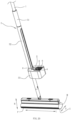
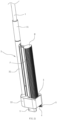
Fig. 1 is a perspective view according to a first embodiment of the present invention (in a normal mopping state); -
Fig. 2 is a perspective view the first embodiment (in a wringing and moving-down state); -
Fig. 3 is a partially sectional view of the first embodiment (in a state where the foam cotton head is moved up); -
Fig. 4 is a partially sectional view of the first embodiment (in a state where the foam cotton head is moved down); -
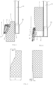
Fig. 5 is a comparison view of two amounts of deformation of the foam cotton head in the first embodiment; -
Fig. 6 is a perspective view of a squeezing mechanism in the first embodiment (in a state where the foam cotton head is moved up); -
Fig. 7 is a perspective view of the squeezing mechanism in the first embodiment (in a state where the foam cotton head is moved down); -
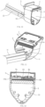
Fig. 8 is a perspective view of a wringing frame in the first embodiment; -
Fig. 9 is a perspective view of the wringing frame equipped with a wringing component according to a second embodiment of the present invention (in a state where the foam cotton head is moved up); -
Fig. 10 is a perspective view of the wringing frame equipped with a wringing component in the second embodiment (when the squeezing plate is deflected for evasion); -
Fig. 11 is a perspective view of the wringing frame equipped with a wringing component according to a third embodiment of the present invention (in a state where the foam cotton head is moved up); -
Fig. 12 is a sectional view of the wringing frame equipped with a wringing component in the third embodiment; -
Fig. 13 is a perspective view of the wringing frame equipped with a wringing component in a fourth embodiment (when the squeezing plate is inclined); -
Fig. 14 is a sectional view of the wringing frame equipped with a wringing component according to the fourth embodiment of the present invention; -
Fig. 15 is a sectional view ofFig. 14 in a direction A-A; -
Fig. 16 is a perspective view the wringing frame equipped with a wringing component according to a fifth embodiment of the present invention (in a mopping state); -
Fig. 17 is a first perspective view the wringing frame equipped with a wringing component in the fifth embodiment(in a state where the foam cotton head is moved up); -
Fig. 18 is a second perspective view the wringing frame equipped with a wringing component in the fifth embodiment (in a state where the foam cotton head is moved up); -
Fig. 19 is a second perspective view the wringing frame equipped with a wringing component in the fifth embodiment (in a state where the foam cotton head is moved down); -
Fig. 20 is a perspective view according to a sixth embodiment of the present invention (in a normal mapping state); -
Fig. 21 is a perspective view of the sixth embodiment (in a wringing and moving-down state); -
Fig. 22 is a partially perspective view of the sixth embodiment (in a state where the foam cotton head is moved up); and -
Fig. 23 is a partially perspective view of the sixth embodiment (in a state where the foam cotton head is moved down). - To enable a further understanding of the present invention content of the invention herein, refer to the detailed description of the invention and the accompanying drawings below:
As shown inFigs. 1-8 , a first embodiment of the present invention is shown. - A self-wringing foam cotton mop with a labor-saving wringing operation is provided, including a
mop rod 1 and afoam cotton head 2. Thefoam cotton head 2 is rotatably connected to a bottom end of themop rod 1. A wringingframe 3 capable of sliding along themop rod 1 is provided on themop rod 1, and the wringingframe 3 has a through hole X for allowing an end face M of thefoam cotton head 2 to pass therethrough. The end face M refers to surfaces of two sides of thefoam cotton head 2 in the lengthwise direction L. A squeezing mechanism capable of moving (e.g., swinging) relative to the wringingframe 3 is provided on an inner front side of the through hole X, so that the position of the squeezing mechanism during an upward movement of thefoam cotton head 2 relative to the wringingframe 3 is different from the position of the squeezing mechanism during a downward movement of thefoam cotton head 2 relative to the wringingframe 3. During the wringing process, thefoam cotton head 2 is rotated to allow the end face M to be aligned with the through hole X, thefoam cotton head 2 enters and passes through the through hole X to squeeze the bottom surface S of thefoam cotton head 2 via the squeezing mechanism so as to realize the wringing operation. During the mopping process, thefoam cotton head 2 is completely separated from the through hole X. In the process of thefoam cotton head 2 enters the through hole X and moves up, the squeezing mechanism that does not swing enables thefoam cotton head 2 to generate a first amount of deformation Δh1 in the thickness direction; and, in the process that thefoam cotton head 2 enters the through hole X and moves down, the swung squeezing mechanism enables thefoam cotton head 2 to generate a second amount of deformation Δh2 in the thickness direction H, where the first amount of deformation Δh1 is greater than the second amount of deformation Δh2. In this embodiment, it should be understood that the amount of deformation is a difference between the thickness of thefoam cotton state 2 under normal conditions and the thickness of thefoam cotton head 2 after being squeezed and deformed. - In the process of the
foam cotton head 2 entering the through hole X to move up, the squeezing mechanism is always kept in a state of gradually inclining towards the bottom surface of thefoal cotton head 2 from the bottom up; and, in the process of thefoam cotton head 2 entering the through hole X to move down, the squeezing mechanism will deflect or displace to allow the upper end of the squeezing mechanism to move away from the bottom surface of thefoam cotton head 2. - In this embodiment, the squeezing mechanism comprises a squeezing
plate 5 and a connectingplate 6. A wringingroller 4 for coming into contact with the bottom surface S of thefoam cotton head 2 is provided on the squeezingplate 5, and the squeezingplate 5 is rotatably constrained within the through hole X and movable up and down within a certain range in an axial direction of the through hole X. One end of the connectingplate 6 is rotatably connected to the wringingframe 3, while other end of the connectingplate 6 is hinged to an upper end of the squeezingplate 5. Anelastic member 7 for allowing a lower end of the connectingplate 6 keep in a trend of deflecting close to the bottom surface S of thefoam cotton head 2 is provided within the through hole X. theelastic member 7 is a torsion spring. A limiting structure for limiting an upward movement of the connectingplate 6 is provided within the through hole X. - In the process of the
foam cotton head 2 entering the through hole X to move up, under the action of theelastic member 7 and the connectingplate 6, the squeezingplate 5 is always kept in a state of gradually inclining towards the bottom surface of thefoam cotton head 2 from the bottom up; and, in the process of thefoam cotton head 2 entering the through hole X to move down, thefoam cotton head 2 can trigger the connectingplate 6 to overcome the elastic force of theelastic member 7 to deflect, and the connectingplate 6 drives the upper end of the squeezingplate 5 to move away from the bottom surface S of thefoam cotton head 2. The limiting structure includes arc-shapedguide grooves 8 formed on left and right inner sidewalls of the through hole X, and guidecolumns 51 inserted into theguide grooves 8 are provided in a middle portion of left and right sides of the squeezingplate 5. By limiting theguide columns 51 through upper inner sidewalls of theguide grooves 8, during the upward movement of thefoam cotton head 2 relative to the through hole X, the squeezingplate 5 is always kept at a position where it is gradually inclined towards the bottom surface of thefoam cotton head 2 from the bottom up. - The wringing
frame 3 consists of a wringinghandle 31, a connectingrod 32 and a wringingtip 33. The wringing handle 31 is sheathed on themop rod 1 and able to slide in the axial direction, the wringinghandle 31 is connected to the wringingtip 33 through the connectingrod 32, and the through hole X is formed on the wringingtip 33. When the wringingtip 33 is located at a lower position, the lower end of thefoam cotton head 2 runs into the through hole X, and the wringingtip 33 transversely extends to form the ground. Therefore, when the wringingtip 33 is located at a lower position, the wringingtip 33 can act as a pedestal, so that the lower end of thefoam cotton head 2 parallel to themop rod 1 is inserted into the through hole X and the mop can be placed vertically. - In this embodiment, the up-down direction refers to the lengthwise direction of the
mop rod 1; the front-rear direction refers to the width direction D of thefoam cotton head 2; and, the left-right direction is perpendicular to the front-rear direction, i.e., the lengthwise direction L of thefoam cotton head 2 in a mopping state, and the thickness direction refers to a direction basically perpendicular to the bottom surface S of thefoam cotton head 2. - The operating principle and process in this embodiment are described below.
- Wringing operation: the
foam bottom head 2 is rotated to be basically parallel to themop rod 1 and directly face the through hole X. The wringing handle 31 is held by one hand, themop rod 1 is held by the other hand, and the wringing handle 31 is pushed to slide up and down relative to themop rod 1, so that thefoam cotton head 2 enters and passes through the through hole X to squeeze the bottom surface S of thefoam cotton head 2 so as to realize the wringing operation. In the process of thefoam cotton head 2 entering the through hole X to move up, due to the action of theelastic member 7 and the connectingplate 6, the squeezingplate 5 is always kept in a state of gradually inclining towards the bottom surface of thefoam cotton head 2 from the bottom up, so that the squeezing passage is a passage with a larger bottom and a smaller top, and it is advantageous for allowing thefoam cotton head 2 to enter the through hole X. Moreover, the squeezing force gradually increases, the foam cotton head can be better dewatered, and the wringing operation is labor-saving. In the process of thefoam cotton head 2 entering the through hole X to move down, thefoam cotton head 2 can trigger the connectingplate 6 to overcome the elastic force of theelastic member 7 to deflect, and the connectingplate 6 drives an upper end of the squeezingplate 5 to move away from the bottom surface S of thefoam cotton head 2. Thus, it is advantageous for thefoam cotton head 2 to downward passing through the squeezing passage. - Particularly in the case where the
foam cotton head 2 is dry, thefoam cotton head 2 will become hard, and in combination with the swingable squeezing mechanism structure of the mop, it is advantageous for the dry and hardfoam cotton head 2 to pass through the through hole X. - Mopping operation: the wringing
frame 3 is held by one hand, themop rod 1 is held by the other hand, and the wringing handle 31 is pulled up to move up to a higher position relative to themop rod 1 until thefoam cotton head 2 is completely separated from the wringingtip 33. At this time, since the wringing handle 31 is located at a higher position, thefoam cotton head 2 is completely separated from the wringingtip 33 during the mopping proves. Therefore, thefoam cotton head 2 is movably connected to the lower end of themop rod 1, thefoam cotton head 2 can be deflected at will during the mopping process, and the operation is more comfortable and reasonable. - As shown in
Figs. 9 and10 , a second embodiment of the present invention is shown. - This embodiment differs from the first embodiment in that: the squeezing mechanism includes a squeezing
plate 5; and a wringingroller 4 adapted to be in contact with the bottom surface of thefoam cotton head 2 is provided on the squeezingplate 5, and a lower end of the squeezingplate 5 is hinged within the through hole X; anelastic member 7 for keeping an upper end of the squeezingplate 5 in a trend of deflecting close to the bottom surface of thefoam cotton head 2 is provided within the through hole X, and theelastic member 7 is a torsion spring; a limitingportion 9 for limiting a rotation position of the squeezingplate 5 is further provided within the through hole X; and, under the combined action of theelastic member 7 and the limitingportion 9, the squeezingplate 5 is always kept in a state of gradually inclining towards the bottom surface S of thefoam cotton head 2 from the bottom up. The upper end of the squeezingplate 5 has a guide surface that extends outward from the through hole and looks like a slope. - The limiting
portion 9 is a stop column for limiting two sides of the bottom surface of the squeezingplate 5 for purpose of avoiding excessive turnover of an upper end of the squeezingplate 5. In this embodiment, theelastic member 7 applies a large force to the squeezingplate 5. In the process of thefoam cotton head 2 entering the through hole X to move down, if the foam cotton head becomes very hard, the forced applied to the squeezingplate 5 by the foam cotton head is larger than the force applied to the squeezingplate 5 by theelastic member 7, so the opening becomes larger and it is advantageous for the foam cotton head to run downward. - As shown in
Figs. 11 and 12 , a third embodiment of the present invention is shown. - This embodiment differs from the first embodiment in that: the squeezing mechanism includes a squeezing
plate 5; a wringingroller 4 for coming into contact with the bottom surface S of thefoam cotton head 2 is provided on the squeezingplate 5, and a lower end of the squeezingplate 5 is hinged within the through hole X; a limitingportion 9 for limiting a rotation position of the squeezingplate 5 is provided within the through hole X, and an upper end of the squeezingplate 5 is locked within the through hole X by a locking structure that can be unlocked; and, in a state where an upper end of the squeezingplate 5 is locked by the locking structure, the squeezingplate 5 is kept at a position where it is gradually inclined towards the bottom surface S of thefoam cotton head 2 from the bottom up. - The locking structure includes a
first lock bar 9a and asecond lock bar 9b which are arranged left and right within the squeezingplate 5 at interval and can slide left and right. Afirst lock hole 10a and asecond lock hole 10 b are formed on left and right sidewalls of the through hole X. A support spring 91 is provided between thefirst lock bar 9a and thesecond lock bar 9b. The support spring 91 keeps thefirst lock bar 9a and thesecond lock bar 9b in a trend of extending outward and being separately inserted into thefirst lock 10a and thesecond lock hole 10b, and thefirst lock bar 9a and thesecond lock bar 9b are exposed from the outer surface of the squeezingplate 5 for allowing them to be driven by a user. - The limiting
portion 9 is a stop column for limiting two sides of the bottom surface of the squeezingplate 5 for purpose of avoiding excessive turnover of the upper end of the squeezingplate 5. In the process of thefoam cotton head 2 entering the through hole X to move down, the squeezingplate 5 is unlocked first. In this way, the squeezingplate 5 can freely swing back and forth, and thefoam cotton head 2 can trigger the squeezingplate 5 and drive the upper end of the squeezingplate 5 to move away from thefoam cotton head 2, so that it is advantageous for thefoam cotton head 2 to downward passing through the squeezing passage. - As shown in
Figs. 13-15 , a fourth embodiment of the present invention is shown. - This embodiment differs from the third embodiment in that: an
elastic member 7 for keeping the upper end of the squeezingplate 5 in a trend of deflecting close to the bottom surface S of thefoam cotton head 2 is provided within the through hole X. - As shown in
Figs. 16-19 , a fifth embodiment of the present invention is shown. - This embodiment differs from the first embodiment in that: the squeezing mechanism includes a squeezing
plate 5; a wringingroller 4 for coming into contact with the bottom surface S of thefoam cotton head 2 is provided on the squeezingplate 5, and an upper end of the squeezingplate 5 is hinged within the through hole X and enables the lower end of the squeezingplate 5 to swing; anelastic member 7 for keeping the lower end of the squeezingplate 5 in a trend of blocking the main through hole X and a limitingportion 9 for limiting a rotation position of the squeezingplate 5 are provided within the through hole X; and, in a state where the lower end of the squeezingplate 5 is overturned to resist against the limitingportion 9, the squeezingplate 5 is kept at a position where it is gradually inclined towards the bottom surface S of thefoam cotton head 2 from the bottom up. - The limiting
portion 9 is a stop column for limiting two sides of the bottom surface of the squeezingplate 5 for purpose of avoiding excessive turnover of the upper end of the squeezingplate 5. In the process of thefoam cotton head 2 entering the through hole X to move down, thefoam cotton head 2 can trigger the squeezingplate 5 and drive the lower end of the squeezingplate 5 to overturn to the outside of the squeezingtip 33 so as to realize evasion. - As shown in
Figs. 20-23 , a sixth embodiment of the present invention is shown. - This embodiment differs from the first embodiment in that: the squeezing mechanisms is adapted for squeezing side faces P of front and rear sides of the
foam cotton head 2; during the upward movement of thefoam cotton head 2 relative to the wringingframe 3, the squeezing mechanisms enable thefoam cotton head 2 to generate the first amount of deformation Δh1 in a width direction D; and, during the downward movement of thefoam cotton head 2 relative to the wringingframe 3, the squeezing mechanisms enable thefoam cotton head 2 to generate the second amount of deformation Δh2 in the width direction D. The wringingframe 3 has a through hole X for allowing an end face M of thefoam cotton head 2 to pass therethrough. There are two squeezing mechanisms which are respectively arranged on front and rear inside the throughhole 31 and can swing relative to the wringingframe 3. During a wringing frame, thefoam cotton head 2 is rotated to allow the end face M to be aligned with the through hole X. In the process that thefoam cotton head 2 enters the through hole X and moves up, the two squeezing mechanisms that do not swing enable thefoam cotton head 2 to generate the first amount of deformation Δh1; and, in the process that thefoam cotton head 2 enters the through hole X and moves down, the two swung squeezing mechanisms enable thefoam cotton head 2 to generate the second amount of deformation Δh2. - In this embodiment, each of the squeezing mechanisms includes a squeezing
plate 5 and a connectingplate 6. A wringingroller 4 for being contact with the side surfaces P of thefoam cotton head 2 is provided on the squeezingplate 5, and the squeezingplate 5 is rotatably constrained within the through hole X and is movable up and down within a certain range in an axial direction of the through hole X. One end of the connectingplate 6 is rotatably connected within the through hole X, while the other end of the connectingplate 6 is hinged to the upper end of the squeezingplate 5. Anelastic member 7 for keeping a lower end of the connectingplate 6 in a trend of deflecting close to the side faces P of thefoam cotton head 2 is provided within the through hole X, and a limiting structure for limiting an upward movement of the connectingplate 6 is further provided within the through hole X. The limiting structure can refer toEmbodiment 1. - Of course, it is also possible that one of the squeezing mechanisms employs the above structure and the other one of the squeezing mechanisms employs a fixed-type inclined squeezing plate structure.
Claims (7)
- A self-wringing foam cotton mop with a labor-saving wringing operation, comprising a mop rod (1) and a foam cotton head (2), wherein:the foam cotton head (2) is rotatably connected to a bottom end of the mop rod (1);a wringing frame (3) is disposed on the mop rod (1);during mopping, the foam cotton head (2) is separated from the wringing frame (3);a squeezing mechanism capable of squeezing the foam cotton head (2) entering the wringing frame (3) is disposed on the wringing frame (3);a position of the squeezing mechanism is changeable, so that the position of the squeezing mechanism when the foam cotton head (2) is moved upward relative to the wringing frame (3) is different from the position of the squeezing mechanism when the foam cotton head (2) is moved downward relative to the wringing frame (3);therefore, a first amount of deformation (Δh1) generated by the foam cotton head (2) during an upward movement of the foam cotton head (2) relative to the wringing frame (3) is greater than the second amount of deformation (Δh2) generated by the foam cotton head (2) during a downward movement of the foam cotton head (2) relative to the wringing frame (3); wherein the squeezing mechanism is adapted for squeezing a bottom surface (S) of the foam cotton head (2) to realize the wringing operation;when the foam cotton head (2) is moved up relative to the wringing frame (3), the squeezing mechanism enables the foam cotton head (2) to generate the first amount of deformation (Δh1) in a thickness direction (H); and,when the foam cotton head (2) is moved down relative to the wringing frame (3), the squeezing mechanism enables the foam cotton head (2) to generate the second amount of deformation (Ah2) in the thickness direction (H); characterized in that:the wringing frame (3) comprises a through hole (X) for allowing an end surface (M) of the foam cotton head (2) to pass therethrough, and the squeezing mechanism is disposed within the through hole (X) and is able to swing relative to the wringing frame (3);during a wringing process, the foam cotton head (2) is rotated to allow the end surface (M) to be aligned with the through hole (X);in the process that the foam cotton head (2) enters the through hole (X) and moves up, the squeezing mechanism that does not swing enables the foam cotton head (2) to generate the first amount of deformation (Δh1); andin the process that the foam cotton head (2) enters the through hole (X) and moves down, the swung squeezing mechanism enables the foam cotton head (2) to generate the second amount of deformation (Δh2).
- The self-wringing foam cotton mop according to claim 1, characterized in that, the squeezing mechanism comprises a squeezing plate (5) and a connecting plate (6);the squeezing plate (5) is adapted to be in contact with the bottom surface (S) of the foam cotton head (2), and the squeezing plate (5) is rotatably constrained on the wringing frame (3) and is movable up and down within a certain range in an axial direction of the wringing frame (3);one end of the connecting plate (6) is rotatably connected to the wringing frame (3), while the other end of the connecting plate (6) is hinged to an upper end of the squeezing plate (5);an elastic member (7) for allowing a lower end of the connecting plate (6) to keep in a trend of deflecting close to the bottom surface (S) of the foam cotton head (2) and a limiting structure for limiting an upward movement of the connecting plate (6) are disposed on the wringing frame (3).
- The self-wringing foam cotton mop according to claim 2, characterized in that, the limiting structure comprises arc-shaped guide grooves (8) formed on left and right inner sidewalls of the through hole (X);guide columns (51) inserted into the guide grooves (8) are disposed in a middle portion of left and right sides of the squeezing plate (5);by limiting the guide columns (51) through upper inner sidewalls of the guide grooves (8), during the upward movement of the foam cotton head (2) relative to the through hole (X), the squeezing plate (5) is always kept at a position where it is gradually inclined towards the bottom surface (S) of the foam cotton head (2) from the bottom up.
- The self-wringing foam cotton mop according to claim 1, characterized in that, the squeezing mechanism comprises a squeezing plate (5), and a wringing roller (4) adapted to be in contact with the bottom surface of the foam cotton head (2) is disposed on the squeezing plate (5);one end of the squeezing plate (5) is hinged to the wringing frame (3);an elastic member (7) for allowing an upper end of the squeezing plate (5) to keep in a trend of deflecting close to the bottom surface (S) of the foam cotton head (2) is disposed on the wringing frame (3), and a limiting portion (9) for limiting the rotation position of the squeezing plate (5) is disposed on the wringing frame (3); and,under a combined action of the elastic member (7) and the limiting portion (9), the squeezing plate (5) is always kept in a state of gradually inclined toward the bottom surface (S) of the foam cotton head (2) from the bottom up.
- The self-wringing foam cotton mop according to claim 1, characterized in that, the squeezing mechanism comprises a squeezing plate (5) for being contact with the bottom surface (S) of the foam cotton head (2);one end of the squeezing plate (5) is hinged to the wringing frame (3);a limiting portion (9) for limiting a rotation position of the squeezing plate (5) is disposed on the wringing frame (3); and,the squeezing plate (5) is locked on the wringing frame (3) by a locking structure that can be unlocked, and the squeezing plate (5) is kept at a position where it is gradually inclined towards the bottom surface (S) of the foam cotton head (2) from the bottom up when an upper end of the squeezing plate (5) is locked by the locking structure.
- A self-wringing foam cotton mop with a labor-saving wringing operation, comprising a mop rod (1) and a foam cotton head (2), wherein:the foam cotton head (2) is rotatably connected to a bottom end of the mop rod (1);a wringing frame (3) is disposed on the mop rod (1);during mopping, the foam cotton head (2) is separated from the wringing frame (3);a squeezing mechanism capable of squeezing the foam cotton head (2) entering the wringing frame (3) is disposed on the wringing frame (3);a position of the squeezing mechanism is changeable, so that the position of the squeezing mechanism when the foam cotton head (2) is moved upward relative to the wringing frame (3) is different from the position of the squeezing mechanism when the foam cotton head (2) is moved downward relative to the wringing frame (3);therefore, a first amount of deformation (Δh1) generated by the foam cotton head (2) during an upward movement of the foam cotton head (2) relative to the wringing frame (3) is greater than the second amount of deformation (Δh2) generated by the foam cotton head (2) during a downward movement of the foam cotton head (2) relative to the wringing frame (3); wherein the squeezing mechanism is adapted for squeezing side surfaces (P) of front and rear sides of the foam cotton head (2);when the foam cotton head (2) is moved up relative to the wringing frame (3), the squeezing mechanism enables the foam cotton head (2) to generate the first amount of deformation (Δh1) in a width direction (D); and,when the foam cotton head (2) is moved down relative to the wringing frame (3), the squeezing mechanism enables the foam cotton head (2) to generate the second amount of deformation (Δh2) in the width direction (D), characterized in that:the wringing frame (3) comprises a through hole (X) for allowing an end surface (M) of the foam cotton head (2) to pass therethrough;two squeezing mechanisms are respectively arranged on front and rear sides inside the through hole (X) and can swing relative to the wringing frame (3);during a wringing process, the foam cotton head (2) is rotated to allow the end surface (M) to be aligned with the through hole (X);in the process that the foam cotton head (2) enters the through hole (X) and moves up, the two squeezing mechanisms that do not swing enable the foam cotton head (2) to generate the first amount of deformation (Δh1); andin the process that the foam cotton head (2) enters the through hole (X) and moves down, the two swung squeezing mechanisms enable the foam cotton head (2) to generate the second amount of deformation (Δh2).
- The self-wringing foam cotton mop according to claim 6, characterized in that, at least one of the squeezing mechanisms comprises a squeezing plate (5) and a connecting plate (6);a wringing roller (4) for being contact with the side surfaces (P) of the foam cotton head (2) is disposed on the squeezing plate (5), and the squeezing plate (5) is rotatably constrained on the wringing frame (3) and is movable up and down within a certain range in an axial direction of the wringing frame (3);one end of the connecting plate (6) is rotatably connected to the wringing frame (3), while the other end of the connecting plate (6) is hinged to an upper end of the squeezing plate (5);an elastic member (7) for keeping a lower end of the connecting plate (6) in a trend of deflecting close to the side surface (P) of the foam cotton head (2) and a limiting structure for limiting an upward movement of the connecting plate (6) are disposed on the wringing frame.
Applications Claiming Priority (2)
| Application Number | Priority Date | Filing Date | Title |
|---|---|---|---|
| CN201710442151.6A CN107595218B (en) | 2017-06-13 | 2017-06-13 | Water-squeezing labor-saving self-squeezing foaming cotton head mop |
| PCT/CN2018/000203 WO2018227946A1 (en) | 2017-06-13 | 2018-06-01 | Self-squeezing mop having foamed cotton head and enabling convenient squeezing operation |
Publications (3)
| Publication Number | Publication Date |
|---|---|
| EP3610769A1 EP3610769A1 (en) | 2020-02-19 |
| EP3610769A4 EP3610769A4 (en) | 2020-12-30 |
| EP3610769B1 true EP3610769B1 (en) | 2023-08-02 |
Family
ID=61059529
Family Applications (1)
| Application Number | Title | Priority Date | Filing Date |
|---|---|---|---|
| EP18818432.9A Active EP3610769B1 (en) | 2017-06-13 | 2018-06-01 | Self-squeezing mop having foamed cotton head and enabling convenient squeezing operation |
Country Status (6)
| Country | Link |
|---|---|
| US (1) | US11071433B2 (en) |
| EP (1) | EP3610769B1 (en) |
| JP (1) | JP3227937U (en) |
| KR (1) | KR102239128B1 (en) |
| CN (1) | CN107595218B (en) |
| WO (1) | WO2018227946A1 (en) |
Families Citing this family (17)
| Publication number | Priority date | Publication date | Assignee | Title |
|---|---|---|---|---|
| CN107595218B (en) * | 2017-06-13 | 2021-02-12 | 宁波德润堂智能科技有限公司 | Water-squeezing labor-saving self-squeezing foaming cotton head mop |
| CN110522375A (en) * | 2018-05-24 | 2019-12-03 | 慈溪市博生塑料制品有限公司 | flat mop cleaning tool |
| CN110522371A (en) * | 2018-05-24 | 2019-12-03 | 慈溪市博生塑料制品有限公司 | Method for cleaning flat mop |
| CN110522372A (en) * | 2018-05-24 | 2019-12-03 | 慈溪市博生塑料制品有限公司 | Flat mop squeezing method |
| CN110859558A (en) * | 2018-08-27 | 2020-03-06 | 宁波德润堂智能科技有限公司 | Foam Mop with Improved Squeeze Head |
| CN110881917A (en) * | 2018-09-07 | 2020-03-17 | 慈溪市博生塑料制品有限公司 | Self-wringing foam cotton mop |
| CN108903863A (en) * | 2018-10-10 | 2018-11-30 | 河北洁仕宝日用塑料制品有限公司 | Wringing mop |
| CN111214185A (en) * | 2018-11-24 | 2020-06-02 | 慈溪市博生塑料制品有限公司 | Self-wringing foam cotton mop |
| CN111820833A (en) * | 2019-04-15 | 2020-10-27 | 袁开靖 | A cleaning bucket and a hand-free mop |
| CN210990047U (en) * | 2019-04-15 | 2020-07-14 | 袁开靖 | Hand-washing-free mop |
| CN111904350A (en) * | 2019-05-10 | 2020-11-10 | 宁波德润堂智能科技有限公司 | Foam cotton mop cleaning tool |
| CN112137537B (en) * | 2019-06-26 | 2025-09-02 | 宁波德润堂智能科技有限公司 | A cleaning tool with a guide structure |
| CN112315393B (en) * | 2019-08-05 | 2025-05-13 | 宁波德润堂智能科技有限公司 | Water squeeze device, foam mop and cleaning tools |
| CN110786792B (en) * | 2019-12-03 | 2025-02-25 | 俞享福 | A collodion mop |
| US11324379B2 (en) * | 2019-12-19 | 2022-05-10 | Tylor Christian ROSS | Mop with interchangeable head mechanisms |
| CN113796804B (en) * | 2020-06-16 | 2025-01-24 | 宁波德润堂智能科技有限公司 | Double-sided squeezing water squeezing device, cleaning tool and self-squeezing water foam mop |
| CN113827153B (en) * | 2020-06-24 | 2025-03-28 | 宁波德润堂智能科技有限公司 | Double-sided squeezing water squeezing device, cleaning tool and self-squeezing water foam mop |
Family Cites Families (13)
| Publication number | Priority date | Publication date | Assignee | Title |
|---|---|---|---|---|
| US2201079A (en) * | 1938-05-05 | 1940-05-14 | Henry J Camden | Wringer mop |
| JPS63315022A (en) * | 1987-06-17 | 1988-12-22 | 山崎産業株式会社 | Mop with squeezee |
| EP0457943B1 (en) * | 1990-05-22 | 1993-07-07 | LEIFHEIT Aktiengesellschaft | Wiping mop |
| US6148465A (en) * | 1999-05-04 | 2000-11-21 | Hsieh; Ming-Ti | Mophead for a sponge mop |
| EP1208788B1 (en) * | 2000-11-15 | 2007-10-24 | LEIFHEIT Aktiengesellschaft | Mop |
| US6588045B2 (en) * | 2001-05-04 | 2003-07-08 | Products Of Tomorrow, Inc. | Roller self-wringing sponge mop with scrubber |
| CN2626415Y (en) | 2003-05-13 | 2004-07-21 | 朱雪林 | Collodion mop |
| CN201409887Y (en) | 2009-05-27 | 2010-02-24 | 王永东 | Inserting-type water squeezing collodion cotton mop |
| CN201453183U (en) | 2009-07-21 | 2010-05-12 | 嘉兴捷顺旅游制品有限公司 | Collodion cotton mop |
| DE102009041640A1 (en) * | 2009-09-17 | 2011-03-24 | Carl Freudenberg Kg | Wiper for wiping floor e.g. parquet floor, has press housing comprising narrow side surfaces, broad side surfaces and opening, where folded wiping plate flanks are partially guided into press housing via opening |
| CN201675886U (en) * | 2010-03-25 | 2010-12-22 | 王永东 | Squeezing-water horizontal mop |
| CN102138771B (en) | 2011-04-22 | 2015-02-04 | 张承志 | Movable multifunctional collodion cotton mop |
| CN107595218B (en) | 2017-06-13 | 2021-02-12 | 宁波德润堂智能科技有限公司 | Water-squeezing labor-saving self-squeezing foaming cotton head mop |
-
2017
- 2017-06-13 CN CN201710442151.6A patent/CN107595218B/en active Active
-
2018
- 2018-06-01 KR KR1020197021843A patent/KR102239128B1/en active Active
- 2018-06-01 WO PCT/CN2018/000203 patent/WO2018227946A1/en not_active Ceased
- 2018-06-01 JP JP2019600051U patent/JP3227937U/en active Active
- 2018-06-01 US US16/622,289 patent/US11071433B2/en active Active
- 2018-06-01 EP EP18818432.9A patent/EP3610769B1/en active Active
Also Published As
| Publication number | Publication date |
|---|---|
| WO2018227946A1 (en) | 2018-12-20 |
| EP3610769A1 (en) | 2020-02-19 |
| KR20190100324A (en) | 2019-08-28 |
| CN107595218A (en) | 2018-01-19 |
| EP3610769A4 (en) | 2020-12-30 |
| US20200196824A1 (en) | 2020-06-25 |
| KR102239128B1 (en) | 2021-04-09 |
| JP3227937U (en) | 2020-09-24 |
| CN107595218B (en) | 2021-02-12 |
| US11071433B2 (en) | 2021-07-27 |
Similar Documents
| Publication | Publication Date | Title |
|---|---|---|
| US11071433B2 (en) | Self-wringing foam cotton mop with labor-saving wringing operation | |
| CN211633152U (en) | A mop head, mop and mopping assembly | |
| CN108498032A (en) | A kind of water squeezing method and cleaning and dewatering squeezing flat mop | |
| CN207785086U (en) | The improved foamed cotton head mop of water squeezing mode | |
| CN206896308U (en) | The crowded frame of foamed cotton head mop | |
| CN107865620A (en) | Foaming cotton mop extracts structure | |
| CN110786792B (en) | A collodion mop | |
| EP2704618B1 (en) | Cleaning member mounting holder for mop and mop | |
| CN207520106U (en) | Flushing operation labour-saving is from water squeezing foamed cotton head mop | |
| CN211066466U (en) | Cleaning tool | |
| JP3140208U (en) | Slide rail automatic storage device | |
| JP2005278683A (en) | Mop | |
| US2866991A (en) | Floor mop having a curved head compressible in a correspondingly curved path | |
| CN208864234U (en) | A foam cotton mop | |
| CN211066460U (en) | a cleaning tool | |
| CN208892463U (en) | Foaming cotton mop extracts structure | |
| CN215687564U (en) | Half-fold squeezing foam cotton mop | |
| CN214387373U (en) | Adjusting mechanism and burnisher of glued membrane head | |
| CN211066449U (en) | foam cotton mop | |
| CN212591976U (en) | Foam mop head | |
| CN212307745U (en) | Water squeezing device, foam cotton mop and cleaning tool | |
| CN223350151U (en) | Cleaning tool based on double-folded foam mop | |
| CN211559979U (en) | Floating squeezing water squeezing device, self-squeezing foam mop and mop cleaning tool | |
| CN209032162U (en) | A kind of collodion squeezing water | |
| CN211961947U (en) | Mop convenient to clean |
Legal Events
| Date | Code | Title | Description |
|---|---|---|---|
| STAA | Information on the status of an ep patent application or granted ep patent |
Free format text: STATUS: THE INTERNATIONAL PUBLICATION HAS BEEN MADE |
|
| PUAI | Public reference made under article 153(3) epc to a published international application that has entered the european phase |
Free format text: ORIGINAL CODE: 0009012 |
|
| STAA | Information on the status of an ep patent application or granted ep patent |
Free format text: STATUS: REQUEST FOR EXAMINATION WAS MADE |
|
| 17P | Request for examination filed |
Effective date: 20191114 |
|
| AK | Designated contracting states |
Kind code of ref document: A1 Designated state(s): AL AT BE BG CH CY CZ DE DK EE ES FI FR GB GR HR HU IE IS IT LI LT LU LV MC MK MT NL NO PL PT RO RS SE SI SK SM TR |
|
| AX | Request for extension of the european patent |
Extension state: BA ME |
|
| DAV | Request for validation of the european patent (deleted) | ||
| DAX | Request for extension of the european patent (deleted) | ||
| A4 | Supplementary search report drawn up and despatched |
Effective date: 20201126 |
|
| RIC1 | Information provided on ipc code assigned before grant |
Ipc: A47L 13/257 20060101ALI20201120BHEP Ipc: A47L 13/146 20060101ALI20201120BHEP Ipc: A47L 13/144 20060101AFI20201120BHEP |
|
| GRAP | Despatch of communication of intention to grant a patent |
Free format text: ORIGINAL CODE: EPIDOSNIGR1 |
|
| STAA | Information on the status of an ep patent application or granted ep patent |
Free format text: STATUS: GRANT OF PATENT IS INTENDED |
|
| INTG | Intention to grant announced |
Effective date: 20230221 |
|
| GRAS | Grant fee paid |
Free format text: ORIGINAL CODE: EPIDOSNIGR3 |
|
| GRAA | (expected) grant |
Free format text: ORIGINAL CODE: 0009210 |
|
| STAA | Information on the status of an ep patent application or granted ep patent |
Free format text: STATUS: THE PATENT HAS BEEN GRANTED |
|
| AK | Designated contracting states |
Kind code of ref document: B1 Designated state(s): AL AT BE BG CH CY CZ DE DK EE ES FI FR GB GR HR HU IE IS IT LI LT LU LV MC MK MT NL NO PL PT RO RS SE SI SK SM TR |
|
| REG | Reference to a national code |
Ref country code: GB Ref legal event code: FG4D |
|
| REG | Reference to a national code |
Ref country code: CH Ref legal event code: EP |
|
| REG | Reference to a national code |
Ref country code: DE Ref legal event code: R096 Ref document number: 602018054669 Country of ref document: DE |
|
| REG | Reference to a national code |
Ref country code: IE Ref legal event code: FG4D |
|
| REG | Reference to a national code |
Ref country code: LT Ref legal event code: MG9D |
|
| REG | Reference to a national code |
Ref country code: NL Ref legal event code: MP Effective date: 20230802 |
|
| REG | Reference to a national code |
Ref country code: AT Ref legal event code: MK05 Ref document number: 1593675 Country of ref document: AT Kind code of ref document: T Effective date: 20230802 |
|
| PG25 | Lapsed in a contracting state [announced via postgrant information from national office to epo] |
Ref country code: GR Free format text: LAPSE BECAUSE OF FAILURE TO SUBMIT A TRANSLATION OF THE DESCRIPTION OR TO PAY THE FEE WITHIN THE PRESCRIBED TIME-LIMIT Effective date: 20231103 |
|
| PG25 | Lapsed in a contracting state [announced via postgrant information from national office to epo] |
Ref country code: IS Free format text: LAPSE BECAUSE OF FAILURE TO SUBMIT A TRANSLATION OF THE DESCRIPTION OR TO PAY THE FEE WITHIN THE PRESCRIBED TIME-LIMIT Effective date: 20231202 |
|
| PG25 | Lapsed in a contracting state [announced via postgrant information from national office to epo] |
Ref country code: SE Free format text: LAPSE BECAUSE OF FAILURE TO SUBMIT A TRANSLATION OF THE DESCRIPTION OR TO PAY THE FEE WITHIN THE PRESCRIBED TIME-LIMIT Effective date: 20230802 Ref country code: RS Free format text: LAPSE BECAUSE OF FAILURE TO SUBMIT A TRANSLATION OF THE DESCRIPTION OR TO PAY THE FEE WITHIN THE PRESCRIBED TIME-LIMIT Effective date: 20230802 Ref country code: PT Free format text: LAPSE BECAUSE OF FAILURE TO SUBMIT A TRANSLATION OF THE DESCRIPTION OR TO PAY THE FEE WITHIN THE PRESCRIBED TIME-LIMIT Effective date: 20231204 Ref country code: NO Free format text: LAPSE BECAUSE OF FAILURE TO SUBMIT A TRANSLATION OF THE DESCRIPTION OR TO PAY THE FEE WITHIN THE PRESCRIBED TIME-LIMIT Effective date: 20231102 Ref country code: NL Free format text: LAPSE BECAUSE OF FAILURE TO SUBMIT A TRANSLATION OF THE DESCRIPTION OR TO PAY THE FEE WITHIN THE PRESCRIBED TIME-LIMIT Effective date: 20230802 Ref country code: LV Free format text: LAPSE BECAUSE OF FAILURE TO SUBMIT A TRANSLATION OF THE DESCRIPTION OR TO PAY THE FEE WITHIN THE PRESCRIBED TIME-LIMIT Effective date: 20230802 Ref country code: LT Free format text: LAPSE BECAUSE OF FAILURE TO SUBMIT A TRANSLATION OF THE DESCRIPTION OR TO PAY THE FEE WITHIN THE PRESCRIBED TIME-LIMIT Effective date: 20230802 Ref country code: IS Free format text: LAPSE BECAUSE OF FAILURE TO SUBMIT A TRANSLATION OF THE DESCRIPTION OR TO PAY THE FEE WITHIN THE PRESCRIBED TIME-LIMIT Effective date: 20231202 Ref country code: HR Free format text: LAPSE BECAUSE OF FAILURE TO SUBMIT A TRANSLATION OF THE DESCRIPTION OR TO PAY THE FEE WITHIN THE PRESCRIBED TIME-LIMIT Effective date: 20230802 Ref country code: GR Free format text: LAPSE BECAUSE OF FAILURE TO SUBMIT A TRANSLATION OF THE DESCRIPTION OR TO PAY THE FEE WITHIN THE PRESCRIBED TIME-LIMIT Effective date: 20231103 Ref country code: FI Free format text: LAPSE BECAUSE OF FAILURE TO SUBMIT A TRANSLATION OF THE DESCRIPTION OR TO PAY THE FEE WITHIN THE PRESCRIBED TIME-LIMIT Effective date: 20230802 Ref country code: AT Free format text: LAPSE BECAUSE OF FAILURE TO SUBMIT A TRANSLATION OF THE DESCRIPTION OR TO PAY THE FEE WITHIN THE PRESCRIBED TIME-LIMIT Effective date: 20230802 |
|
| PG25 | Lapsed in a contracting state [announced via postgrant information from national office to epo] |
Ref country code: PL Free format text: LAPSE BECAUSE OF FAILURE TO SUBMIT A TRANSLATION OF THE DESCRIPTION OR TO PAY THE FEE WITHIN THE PRESCRIBED TIME-LIMIT Effective date: 20230802 |
|
| PG25 | Lapsed in a contracting state [announced via postgrant information from national office to epo] |
Ref country code: ES Free format text: LAPSE BECAUSE OF FAILURE TO SUBMIT A TRANSLATION OF THE DESCRIPTION OR TO PAY THE FEE WITHIN THE PRESCRIBED TIME-LIMIT Effective date: 20230802 |
|
| PG25 | Lapsed in a contracting state [announced via postgrant information from national office to epo] |
Ref country code: SM Free format text: LAPSE BECAUSE OF FAILURE TO SUBMIT A TRANSLATION OF THE DESCRIPTION OR TO PAY THE FEE WITHIN THE PRESCRIBED TIME-LIMIT Effective date: 20230802 Ref country code: RO Free format text: LAPSE BECAUSE OF FAILURE TO SUBMIT A TRANSLATION OF THE DESCRIPTION OR TO PAY THE FEE WITHIN THE PRESCRIBED TIME-LIMIT Effective date: 20230802 Ref country code: ES Free format text: LAPSE BECAUSE OF FAILURE TO SUBMIT A TRANSLATION OF THE DESCRIPTION OR TO PAY THE FEE WITHIN THE PRESCRIBED TIME-LIMIT Effective date: 20230802 Ref country code: EE Free format text: LAPSE BECAUSE OF FAILURE TO SUBMIT A TRANSLATION OF THE DESCRIPTION OR TO PAY THE FEE WITHIN THE PRESCRIBED TIME-LIMIT Effective date: 20230802 Ref country code: DK Free format text: LAPSE BECAUSE OF FAILURE TO SUBMIT A TRANSLATION OF THE DESCRIPTION OR TO PAY THE FEE WITHIN THE PRESCRIBED TIME-LIMIT Effective date: 20230802 Ref country code: CZ Free format text: LAPSE BECAUSE OF FAILURE TO SUBMIT A TRANSLATION OF THE DESCRIPTION OR TO PAY THE FEE WITHIN THE PRESCRIBED TIME-LIMIT Effective date: 20230802 Ref country code: SK Free format text: LAPSE BECAUSE OF FAILURE TO SUBMIT A TRANSLATION OF THE DESCRIPTION OR TO PAY THE FEE WITHIN THE PRESCRIBED TIME-LIMIT Effective date: 20230802 |
|
| REG | Reference to a national code |
Ref country code: DE Ref legal event code: R097 Ref document number: 602018054669 Country of ref document: DE |
|
| PG25 | Lapsed in a contracting state [announced via postgrant information from national office to epo] |
Ref country code: IT Free format text: LAPSE BECAUSE OF FAILURE TO SUBMIT A TRANSLATION OF THE DESCRIPTION OR TO PAY THE FEE WITHIN THE PRESCRIBED TIME-LIMIT Effective date: 20230802 |
|
| PLBE | No opposition filed within time limit |
Free format text: ORIGINAL CODE: 0009261 |
|
| STAA | Information on the status of an ep patent application or granted ep patent |
Free format text: STATUS: NO OPPOSITION FILED WITHIN TIME LIMIT |
|
| 26N | No opposition filed |
Effective date: 20240503 |
|
| PG25 | Lapsed in a contracting state [announced via postgrant information from national office to epo] |
Ref country code: SI Free format text: LAPSE BECAUSE OF FAILURE TO SUBMIT A TRANSLATION OF THE DESCRIPTION OR TO PAY THE FEE WITHIN THE PRESCRIBED TIME-LIMIT Effective date: 20230802 |
|
| PG25 | Lapsed in a contracting state [announced via postgrant information from national office to epo] |
Ref country code: BG Free format text: LAPSE BECAUSE OF FAILURE TO SUBMIT A TRANSLATION OF THE DESCRIPTION OR TO PAY THE FEE WITHIN THE PRESCRIBED TIME-LIMIT Effective date: 20230802 |
|
| PG25 | Lapsed in a contracting state [announced via postgrant information from national office to epo] |
Ref country code: BG Free format text: LAPSE BECAUSE OF FAILURE TO SUBMIT A TRANSLATION OF THE DESCRIPTION OR TO PAY THE FEE WITHIN THE PRESCRIBED TIME-LIMIT Effective date: 20230802 |
|
| PG25 | Lapsed in a contracting state [announced via postgrant information from national office to epo] |
Ref country code: MC Free format text: LAPSE BECAUSE OF FAILURE TO SUBMIT A TRANSLATION OF THE DESCRIPTION OR TO PAY THE FEE WITHIN THE PRESCRIBED TIME-LIMIT Effective date: 20230802 |
|
| REG | Reference to a national code |
Ref country code: CH Ref legal event code: PL |
|
| PG25 | Lapsed in a contracting state [announced via postgrant information from national office to epo] |
Ref country code: LU Free format text: LAPSE BECAUSE OF NON-PAYMENT OF DUE FEES Effective date: 20240601 |
|
| PG25 | Lapsed in a contracting state [announced via postgrant information from national office to epo] |
Ref country code: IE Free format text: LAPSE BECAUSE OF NON-PAYMENT OF DUE FEES Effective date: 20240601 |
|
| PG25 | Lapsed in a contracting state [announced via postgrant information from national office to epo] |
Ref country code: CH Free format text: LAPSE BECAUSE OF NON-PAYMENT OF DUE FEES Effective date: 20240630 Ref country code: BE Free format text: LAPSE BECAUSE OF NON-PAYMENT OF DUE FEES Effective date: 20240630 |
|
| REG | Reference to a national code |
Ref country code: BE Ref legal event code: MM Effective date: 20240630 |
|
| PGFP | Annual fee paid to national office [announced via postgrant information from national office to epo] |
Ref country code: DE Payment date: 20250626 Year of fee payment: 8 |
|
| PGFP | Annual fee paid to national office [announced via postgrant information from national office to epo] |
Ref country code: GB Payment date: 20250627 Year of fee payment: 8 |
|
| PGFP | Annual fee paid to national office [announced via postgrant information from national office to epo] |
Ref country code: FR Payment date: 20250627 Year of fee payment: 8 |
|
| PG25 | Lapsed in a contracting state [announced via postgrant information from national office to epo] |
Ref country code: CY Free format text: LAPSE BECAUSE OF FAILURE TO SUBMIT A TRANSLATION OF THE DESCRIPTION OR TO PAY THE FEE WITHIN THE PRESCRIBED TIME-LIMIT; INVALID AB INITIO Effective date: 20180601 |
|
| PG25 | Lapsed in a contracting state [announced via postgrant information from national office to epo] |
Ref country code: HU Free format text: LAPSE BECAUSE OF FAILURE TO SUBMIT A TRANSLATION OF THE DESCRIPTION OR TO PAY THE FEE WITHIN THE PRESCRIBED TIME-LIMIT; INVALID AB INITIO Effective date: 20180601 |