EP3610722B1 - Double rope pet leash - Google Patents
Double rope pet leash Download PDFInfo
- Publication number
- EP3610722B1 EP3610722B1 EP18209690.9A EP18209690A EP3610722B1 EP 3610722 B1 EP3610722 B1 EP 3610722B1 EP 18209690 A EP18209690 A EP 18209690A EP 3610722 B1 EP3610722 B1 EP 3610722B1
- Authority
- EP
- European Patent Office
- Prior art keywords
- leash
- assembly
- shaft
- cavity
- pressed
- Prior art date
- Legal status (The legal status is an assumption and is not a legal conclusion. Google has not performed a legal analysis and makes no representation as to the accuracy of the status listed.)
- Active
Links
Images

Classifications
-
- A—HUMAN NECESSITIES
- A01—AGRICULTURE; FORESTRY; ANIMAL HUSBANDRY; HUNTING; TRAPPING; FISHING
- A01K—ANIMAL HUSBANDRY; AVICULTURE; APICULTURE; PISCICULTURE; FISHING; REARING OR BREEDING ANIMALS, NOT OTHERWISE PROVIDED FOR; NEW BREEDS OF ANIMALS
- A01K27/00—Leads or collars, e.g. for dogs
- A01K27/003—Leads, leashes
-
- A—HUMAN NECESSITIES
- A01—AGRICULTURE; FORESTRY; ANIMAL HUSBANDRY; HUNTING; TRAPPING; FISHING
- A01K—ANIMAL HUSBANDRY; AVICULTURE; APICULTURE; PISCICULTURE; FISHING; REARING OR BREEDING ANIMALS, NOT OTHERWISE PROVIDED FOR; NEW BREEDS OF ANIMALS
- A01K27/00—Leads or collars, e.g. for dogs
- A01K27/005—Quick-couplings, safety-couplings or shock-absorbing devices between leash and collar
Definitions
- the disclosure belongs to the technical field of pet leashes, in particular to a double rope pet leash.
- pet leash buckles on the market are typically designed with only one position for connection, and only one leash can be fixedly connected, which lacks flexibility in use. For users having more than one pet, there are many inconveniences in actual use.
- Chinese utility model publication CN204707709U discloses a multifunctional pet leash which includes a housing provided with a handle and a leash disposed in the housing, characterized in that the housing is formed by two symmetrical half bodies. A gap is formed between the two half bodies for the leash to extend out of the housing. The leash is provided with a bead outside the housing. Storage slots are respectively disposed on both sides of the housing. The leash further includes a plurality of functional covers that may be threadedly connected to the storage slot.
- the housing and the handle are an integral structure.
- Patent specification DE 102015116415 A1 describes a leash for restraining animals, and, in particular a locking device for releasably connecting an additional leash to an existing leash, so that a simultaneous restraint of two animals is made possible.
- the double rope pet leash of DE 102015116415 further comprises an open-close assembly.
- the present invention provides a double rope pet leash as detailed in claim 1.
- Advantageous features are provided in the dependent claims.
- a double rope pet leash includes a leash body and a leash cavity located in the leash body.
- the leash body is connected with a first leash assembly and a second leash assembly.
- the first leash assembly is fixed on the leash body.
- the second leash assembly is located within the leash cavity and is rotatably connected to the leash body.
- the double rope pet further includes an open-close assembly connected to the leash body and capable of opening or closing the leash cavity.
- the above-described double rope pet leash further includes a first leash rope that is pressed on a surface of the first leash assembly, and a second leash rope that is pressed on a surface of the second leash assembly.
- a first leash assembly includes a first leash shaft integrally formed with the leash body.
- the first leash shaft and the leash body cooperatively form a boundary of the leash cavity.
- the first leash rope is pressed on a surface at one end of the first leash shaft close to the leash cavity.
- the open-close assembly includes a knob and a torsion bar that are fixedly connected to each other.
- the torsion bar is rotatably connected to the leash body.
- the knob is rotatable to allow the torsion bar to pass through the first leash shaft and be pressed on an inner surface of the leash body.
- the inner surface of the leash body has a sealed groove recessed toward inside of the leash body, and the axis of the torsion bar passes through a center of the closed groove.
- the cross-sectional area of the knob is larger than the cross-sectional area of the torsion bar.
- the second leash assembly includes a second leash shaft that is located in the leash cavity and is fixedly connected to the leash body at both ends.
- the second leash assembly further includes a roller sleeved on the second leash shaft and rotatable relative to the second leash shaft, wherein the second leash rope is pressed on the surface of the roller.
- the second leash assembly includes a leash shaft. Both ends of the leash shaft are respectively rotatably connected to the leash body through a short connecting rod. A cross-sectional area of the leash shaft is gradually reduced toward a center thereof from the both ends. The second leash rope is pressed at a center of the leash shaft.
- a double rope pet leash includes a leash body 1.
- a leash cavity 2 is located in the leash body 1.
- the leash body 1 is connected with a first leash assembly 3 and a second leash assembly 4.
- the first leash assembly 3 is fixedly connected with the leash body 1.
- the second leash assembly 4 is located in the leash cavity 2 and is rotatably connected with the leash body 1.
- the first leash rope 5 is pressed on a surface of the first leash assembly 3.
- the second leash rope 6 is pressed on a surface of the second leash assembly 4.
- An open-close assembly 7 connected to the leash body 1 and capable of opening or closing the leash cavity 2 is further included.
- the leash cavity 2 when in use, the leash cavity 2 is opened by the open-close assembly 7, the first leash rope 5 and the second leash rope 6 are respectively pressed on the surfaces of the first leash assembly 3 and the second leash assembly 4, and then the leash cavity 2 is closed by the open-close assembly 7, thereby preventing the first leash rope 5 and the second leash rope 6 from coming out of the leash cavity 2 during use.
- the disclosure may achieve the purpose of connecting two leash ropes simultaneously and expand the application range of the product.
- the first leash assembly 3 includes a first leash shaft 31 integrally formed with the leash body 1, which facilitates to secure connection of the first leash shaft 31 and the leash body 1.
- the first leash shaft 31 and the leash body 1 cooperatively form a boundary of the leash cavity 2, which simplifies the product structure and makes the operation easier while reducing the manufacturing cost.
- the first leash rope 5 is pressed on a surface at one end of the first leash shaft 31 close to the leash cavity 2.
- the open-close assembly 7 includes a knob 71 and a torsion bar 72 that are fixedly connected to each other.
- the torsion bar 72 is rotatably connected to the leash body 1.
- the knob 71 may be rotated such that the torsion bar 72 passes through the first leash shaft 31 and is pressed on an inner surface of the leash body 1, thereby controlling the torsion bar 72 to move in an axial direction by rotating the knob 71 and achieving the opening and closing of the leash cavity 2.
- the inner surface of the leash body 1 further has a sealed groove 73 recessed toward inside of the leash body 1, and an axis of the torsion bar 72 passes through a center of the sealed groove 73.
- the knob 71 is rotated to make the torsion bar 72 to be pressed on the inner surface of the leash body 1, an end portion of the torsion bar 72 is located in the sealed groove 73, which further ensures that the first leash rope 5 and the second leash rope 6 do not come out of the leash cavity 2 during use.
- the knob 71 has a cross-sectional area greater than a cross-sectional area of the torsion bar 72, which facilitates rotation of the torsion bar 72.
- the second leash assembly 4 includes a second leash shaft 41 located in the leash cavity 2 and fixedly connected to the leash body 1 at both ends, and further includes a roller 42 sleeved on the second leash shaft 41 and rotatable relative to the second leash shaft 41.
- the second leash rope 6 is pressed on a surface of the roller 42 so as to reduce frictional force on the second leash rope 6 during use, thereby improving flexibility during use.
- the second leash assembly 4 of such structure is more suitable for the second leash rope 6 having a flat-shape.
- This embodiment is substantially the same as the structure of embodiment 1, and difference lies merely in the specific structure of the second leash assembly 4.
- the second leash assembly 4 includes a leash shaft 43. Both ends of the leash shaft 43 are respectively rotatably connected to the leash body 1 through a short connecting rod 44. A cross-sectional area of the leash shaft 43 is gradually reduced from the both ends toward a center thereof, that is, the leash shaft 43 is in the shape of a dumbbell which is thin in the middle and thick at both ends.
- the second leash rope 6 is pressed at a center of the leash shaft 43, so that the second leash rope 6 is not severely swung to the right and left during use, and the second leash assembly 4 with such structure is more suitable for the second leash rope 6 in a cylindrical shape.
Landscapes
- Life Sciences & Earth Sciences (AREA)
- Environmental Sciences (AREA)
- Animal Husbandry (AREA)
- Biodiversity & Conservation Biology (AREA)
- Housing For Livestock And Birds (AREA)
- Surgical Instruments (AREA)
Description
- The disclosure belongs to the technical field of pet leashes, in particular to a double rope pet leash.
- At present, pet leash buckles on the market are typically designed with only one position for connection, and only one leash can be fixedly connected, which lacks flexibility in use. For users having more than one pet, there are many inconveniences in actual use.
- For example, Chinese utility model publication
CN204707709U discloses a multifunctional pet leash which includes a housing provided with a handle and a leash disposed in the housing, characterized in that the housing is formed by two symmetrical half bodies. A gap is formed between the two half bodies for the leash to extend out of the housing. The leash is provided with a bead outside the housing. Storage slots are respectively disposed on both sides of the housing. The leash further includes a plurality of functional covers that may be threadedly connected to the storage slot. The housing and the handle are an integral structure. - The above disclosure has high practicability with complete functions, but it still does not solve the problem that only one leash can be fixedly connected.
- The relevant state of the art is represented by
US 2015/090196 A1 ,DE 102015116415 A1 ,JP 3163755 U US 2014/216360 A1 ,US 4879972 A1 ,US 2009/139464 A1 andEP 0126190 A1 .
Patent specificationDE 102015116415 A1 describes a leash for restraining animals, and, in particular a locking device for releasably connecting an additional leash to an existing leash, so that a simultaneous restraint of two animals is made possible. The double rope pet leash ofDE 102015116415 further comprises an open-close assembly. - The present invention provides a double rope pet leash as detailed in
claim 1. Advantageous features are provided in the dependent claims. - In order to achieve the above purpose, the present disclosure adopts the following technical solution.
- A double rope pet leash includes a leash body and a leash cavity located in the leash body. The leash body is connected with a first leash assembly and a second leash assembly. The first leash assembly is fixed on the leash body. The second leash assembly is located within the leash cavity and is rotatably connected to the leash body. The double rope pet further includes an open-close assembly connected to the leash body and capable of opening or closing the leash cavity.
- The above-described double rope pet leash further includes a first leash rope that is pressed on a surface of the first leash assembly, and a second leash rope that is pressed on a surface of the second leash assembly.
- In the above-described double rope pet leash, a first leash assembly includes a first leash shaft integrally formed with the leash body. The first leash shaft and the leash body cooperatively form a boundary of the leash cavity. The first leash rope is pressed on a surface at one end of the first leash shaft close to the leash cavity.
- In the above-mentioned double rope pet leash, the open-close assembly includes a knob and a torsion bar that are fixedly connected to each other. The torsion bar is rotatably connected to the leash body. The knob is rotatable to allow the torsion bar to pass through the first leash shaft and be pressed on an inner surface of the leash body.
- In the above-described double rope pet leash, the inner surface of the leash body has a sealed groove recessed toward inside of the leash body, and the axis of the torsion bar passes through a center of the closed groove.
- In the above-described double rope pet leash, the cross-sectional area of the knob is larger than the cross-sectional area of the torsion bar.
- In the above-described double rope pet leash, the second leash assembly includes a second leash shaft that is located in the leash cavity and is fixedly connected to the leash body at both ends. The second leash assembly further includes a roller sleeved on the second leash shaft and rotatable relative to the second leash shaft, wherein the second leash rope is pressed on the surface of the roller.
- In the above-mentioned double rope pet leash, the second leash assembly includes a leash shaft. Both ends of the leash shaft are respectively rotatably connected to the leash body through a short connecting rod. A cross-sectional area of the leash shaft is gradually reduced toward a center thereof from the both ends. The second leash rope is pressed at a center of the leash shaft.
- As compared with related art, the advantageous effects of the disclosure are:
- 1. The disclosure is capable of achieving the purpose of connecting two leash ropes simultaneously, and expands the application range of the product.
- 2. The disclosure is adaptable to different shapes of leash rope by changing the shape of the second leash assembly, and has simple structure while being easy to operate, convenient for use and maintenance, and is suitable for large-scale production and use.
- In order to make the aforementioned features and advantages of the disclosure more comprehensible, embodiments accompanying figures are described in detail below.
-
-
FIG. 1 is a schematic structural view illustrating that an open-close assembly ofembodiment 1 is opened. -
FIG. 2 is a schematic structural view illustrating that the open-close assembly ofembodiment 1 is closed. -
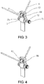
FIG. 3 is a schematic structural view illustrating that the open-close assembly of embodiment 2 is opened. -
FIG. 4 is a schematic structural view illustrating that the open-close assembly of embodiment 2 is closed. - The present disclosure is further described in detail below with reference to the drawings and specific embodiments.
- Referring to
FIG. 1 and FIG. 2 , a double rope pet leash includes aleash body 1. A leash cavity 2 is located in theleash body 1. Theleash body 1 is connected with a first leash assembly 3 and a second leash assembly 4. The first leash assembly 3 is fixedly connected with theleash body 1. The second leash assembly 4 is located in the leash cavity 2 and is rotatably connected with theleash body 1. Thefirst leash rope 5 is pressed on a surface of the first leash assembly 3. Thesecond leash rope 6 is pressed on a surface of the second leash assembly 4. An open-close assembly 7 connected to theleash body 1 and capable of opening or closing the leash cavity 2 is further included. - In the disclosure, when in use, the leash cavity 2 is opened by the open-
close assembly 7, thefirst leash rope 5 and thesecond leash rope 6 are respectively pressed on the surfaces of the first leash assembly 3 and the second leash assembly 4, and then the leash cavity 2 is closed by the open-close assembly 7, thereby preventing thefirst leash rope 5 and thesecond leash rope 6 from coming out of the leash cavity 2 during use. With such configuration, the disclosure may achieve the purpose of connecting two leash ropes simultaneously and expand the application range of the product. - As shown in
FIG. 1 , the first leash assembly 3 includes afirst leash shaft 31 integrally formed with theleash body 1, which facilitates to secure connection of thefirst leash shaft 31 and theleash body 1. Thefirst leash shaft 31 and theleash body 1 cooperatively form a boundary of the leash cavity 2, which simplifies the product structure and makes the operation easier while reducing the manufacturing cost. Thefirst leash rope 5 is pressed on a surface at one end of thefirst leash shaft 31 close to the leash cavity 2. - As shown in
FIG. 3 , the open-close assembly 7 includes aknob 71 and atorsion bar 72 that are fixedly connected to each other. Thetorsion bar 72 is rotatably connected to theleash body 1. Theknob 71 may be rotated such that thetorsion bar 72 passes through thefirst leash shaft 31 and is pressed on an inner surface of theleash body 1, thereby controlling thetorsion bar 72 to move in an axial direction by rotating theknob 71 and achieving the opening and closing of the leash cavity 2. - Preferably, the inner surface of the
leash body 1 further has a sealedgroove 73 recessed toward inside of theleash body 1, and an axis of thetorsion bar 72 passes through a center of the sealedgroove 73. In this manner, when theknob 71 is rotated to make thetorsion bar 72 to be pressed on the inner surface of theleash body 1, an end portion of thetorsion bar 72 is located in the sealedgroove 73, which further ensures that thefirst leash rope 5 and thesecond leash rope 6 do not come out of the leash cavity 2 during use. - Preferably, the
knob 71 has a cross-sectional area greater than a cross-sectional area of thetorsion bar 72, which facilitates rotation of thetorsion bar 72. - As shown in
FIG. 1 , the second leash assembly 4 includes asecond leash shaft 41 located in the leash cavity 2 and fixedly connected to theleash body 1 at both ends, and further includes a roller 42 sleeved on thesecond leash shaft 41 and rotatable relative to thesecond leash shaft 41. Thesecond leash rope 6 is pressed on a surface of the roller 42 so as to reduce frictional force on thesecond leash rope 6 during use, thereby improving flexibility during use. The second leash assembly 4 of such structure is more suitable for thesecond leash rope 6 having a flat-shape. - This embodiment is substantially the same as the structure of
embodiment 1, and difference lies merely in the specific structure of the second leash assembly 4. - As shown in
FIG. 3 and FIG. 4 , the second leash assembly 4 includes aleash shaft 43. Both ends of theleash shaft 43 are respectively rotatably connected to theleash body 1 through a short connectingrod 44. A cross-sectional area of theleash shaft 43 is gradually reduced from the both ends toward a center thereof, that is, theleash shaft 43 is in the shape of a dumbbell which is thin in the middle and thick at both ends. Thesecond leash rope 6 is pressed at a center of theleash shaft 43, so that thesecond leash rope 6 is not severely swung to the right and left during use, and the second leash assembly 4 with such structure is more suitable for thesecond leash rope 6 in a cylindrical shape. - The specific embodiments described herein are merely illustrative of the spirit of the disclosure. A person skilled in the art may make various modifications or additions to the specific embodiments described herein or replace them in a similar manner without departing from the disclosure or exceeding beyond the scope defined by claims.
Claims (4)
- A double line pet leash, the pet leash comprising a body (1) and a cavity located in the body , wherein the body is connected to a first assembly (3) and a second assembly (4), the first assembly is fixedly connected to the body and wherein the first assembly (3) comprises a first shaft (31) integrally formed with the body (1), wherein the first shaft and the body cooperatively form a boundary of the cavity (2), and the second assembly is located within the cavity and is rotatably connected to the body and wherein the second assembly (4) comprises a second shaft (41) located in the cavity (2) and fixedly connected to the body (1) at both ends, the second assembly further comprises a roller (42) sleeved on the second shaft and rotatable relative to the second shaft, and a second leash line (6) is pressed on a surface of the roller, the pet leash further comprising an open-close assembly (7) connected to the body (1) and capable of opening or closing the cavity (2), a first leash line (5) pressed on a surface of the first assembly (3) and the second leash line (6) pressed on a surface of the second assembly (4), wherein the first leash line (5) is pressed on a surface at one end of the first shaft (31) close to the cavity (2); and
wherein the open-close assembly (7) comprises a knob (71) and a torsion bar (72) fixedly connected to each other, the torsion bar is rotatably connected to the body (1), the knob is rotatable to allow the torsion bar to pass through the first shaft (31) and be pressed on an inner surface of the body (1). - The double line pet leash according to claim 1, wherein the inner surface of the body (1) has a sealed groove (73) recessed toward the inside of the body, an axis of the torsion bar (72) passes through a center of the sealed groove (73).
- The double line pet leash according to claim 1, wherein the knob (71) has a cross-sectional area greater than a cross-sectional area of the torsion bar (72).
- The double line pet leash according to claim 1, wherein the second assembly (4) comprises a shaft (43), both ends of the shaft are respectively rotatably connected to the body (1) through a short connection rod (44), a cross-sectional area of the shaft is gradually reduced from the both ends toward a center thereof, and the second leash line (6) is pressed in a center of the shaft (43).
Priority Applications (1)
| Application Number | Priority Date | Filing Date | Title |
|---|---|---|---|
| PL18209690T PL3610722T3 (en) | 2018-08-15 | 2018-11-30 | Double rope pet leash |
Applications Claiming Priority (1)
| Application Number | Priority Date | Filing Date | Title |
|---|---|---|---|
| CN201821320324.3U CN208821465U (en) | 2018-08-15 | 2018-08-15 | Dibit rope pet tractor |
Publications (2)
| Publication Number | Publication Date |
|---|---|
| EP3610722A1 EP3610722A1 (en) | 2020-02-19 |
| EP3610722B1 true EP3610722B1 (en) | 2020-12-23 |
Family
ID=64572132
Family Applications (1)
| Application Number | Title | Priority Date | Filing Date |
|---|---|---|---|
| EP18209690.9A Active EP3610722B1 (en) | 2018-08-15 | 2018-11-30 | Double rope pet leash |
Country Status (5)
| Country | Link |
|---|---|
| US (1) | US10834903B2 (en) |
| EP (1) | EP3610722B1 (en) |
| CN (1) | CN208821465U (en) |
| ES (1) | ES2857720T3 (en) |
| PL (1) | PL3610722T3 (en) |
Families Citing this family (2)
| Publication number | Priority date | Publication date | Assignee | Title |
|---|---|---|---|---|
| CN112997912A (en) * | 2021-02-07 | 2021-06-22 | 苏州佩德漫特工贸有限公司 | Pet tractor |
| US20230055110A1 (en) * | 2021-08-19 | 2023-02-23 | Timothy Reven Everette Cusack | Multi-pet leash |
Family Cites Families (14)
| Publication number | Priority date | Publication date | Assignee | Title |
|---|---|---|---|---|
| US3853283A (en) * | 1973-06-04 | 1974-12-10 | J Croce | Retractable leash device |
| US3937418A (en) * | 1975-01-13 | 1976-02-10 | Lawrence Peska Associates, Inc. | Retractable dog leash |
| EP0126190A1 (en) * | 1983-05-16 | 1984-11-28 | Donald Joseph Salmon | Dog lead or collar |
| US4879972A (en) * | 1987-10-09 | 1989-11-14 | Crowe Dennis E | Double pet walker |
| US6273029B1 (en) * | 1995-07-19 | 2001-08-14 | Panje L. Gish | Anti-tangle/twist multi-animal walking leash |
| US5681225A (en) * | 1996-10-11 | 1997-10-28 | Cary; John F. | Golf club swing training apparatus |
| DE29804615U1 (en) * | 1998-03-09 | 1998-05-20 | Bogdahn-Technik GmbH, 22941 Bargteheide | Leash device for a line that can be rolled up and unrolled for guiding animals |
| US20090139464A1 (en) * | 2007-12-04 | 2009-06-04 | Rose America Corporation | Animal Restraint with Snap Hook and Buckle |
| DE202010004484U1 (en) * | 2010-04-03 | 2011-08-26 | Flexi-Bogdahn Technik Gmbh & Co. Kg | Braking device for a pulley of a mechanically wound up and unwindable line for guiding animals |
| JP3163755U (en) * | 2010-08-19 | 2010-10-28 | 昭雄 村越 | Pet mooring equipment |
| GB2490332B (en) * | 2011-04-21 | 2014-09-03 | John Finlan | Animal lead |
| WO2013165922A1 (en) * | 2012-05-01 | 2013-11-07 | Pb&Jm, Llc | Detangling lead assembly |
| DK178330B1 (en) * | 2014-10-15 | 2015-12-14 | Smart Done Solutions Aps | Locking device for pet & dog leash |
| CN204707709U (en) | 2015-06-12 | 2015-10-21 | 浙江天下实业有限公司 | Multifunctional pet tractor |
-
2018
- 2018-08-15 CN CN201821320324.3U patent/CN208821465U/en active Active
- 2018-11-30 PL PL18209690T patent/PL3610722T3/en unknown
- 2018-11-30 EP EP18209690.9A patent/EP3610722B1/en active Active
- 2018-11-30 ES ES18209690T patent/ES2857720T3/en active Active
- 2018-12-12 US US16/217,050 patent/US10834903B2/en active Active
Non-Patent Citations (1)
| Title |
|---|
| None * |
Also Published As
| Publication number | Publication date |
|---|---|
| PL3610722T3 (en) | 2021-06-14 |
| US20200053985A1 (en) | 2020-02-20 |
| EP3610722A1 (en) | 2020-02-19 |
| ES2857720T3 (en) | 2021-09-29 |
| US10834903B2 (en) | 2020-11-17 |
| CN208821465U (en) | 2019-05-07 |
Similar Documents
| Publication | Publication Date | Title |
|---|---|---|
| CN109042377B (en) | Explosion-proof pet tractor that dashes and lock | |
| WO2001001027A8 (en) | Valve intended to be used in alumina production plants | |
| US10834903B2 (en) | Double rope pet leash | |
| EP2607570A1 (en) | Articulation device for a foldable awning arm | |
| EP3361031B1 (en) | Damping device | |
| CN102003456A (en) | Hinge device and electronic apparatus using the hinge device | |
| CN201786088U (en) | Handle core assembly for handle lock | |
| CN205937688U (en) | Can be from two -way cable mechanism of replying | |
| CN202055620U (en) | handle mechanism | |
| EP2683896A1 (en) | Disassembleable hinge and piece of furniture using the same | |
| US11819988B2 (en) | Locking mechanism for enabling fishing plier to remain closed state | |
| CN203271317U (en) | Coded lock of key box | |
| CN208821462U (en) | Damp type pet tractor | |
| CN211549260U (en) | Hinge structure with damping effect | |
| CN102658910A (en) | Anti-counterfeiting structure of bottle cap and bottle cap for same | |
| CN208592868U (en) | A foldable rotatable knife | |
| KR101540882B1 (en) | Central axis unit structure for beauty art scissor | |
| CN213510092U (en) | Toilet cover plate damping device | |
| CN208392084U (en) | A kind of novel button jack knife | |
| CN209959924U (en) | Locking valve | |
| ITBO970284A1 (en) | HANDLE POSITIONING DEVICE. | |
| CN216425552U (en) | Quick locking and opening device for quick dispersion tank | |
| KR101223619B1 (en) | A safty turning apparatus for a motor fan | |
| CN113089541A (en) | Core device and quick door opening device with same | |
| CN218588763U (en) | Cup lid and flip positioning structure thereof |
Legal Events
| Date | Code | Title | Description |
|---|---|---|---|
| PUAI | Public reference made under article 153(3) epc to a published international application that has entered the european phase |
Free format text: ORIGINAL CODE: 0009012 |
|
| STAA | Information on the status of an ep patent application or granted ep patent |
Free format text: STATUS: REQUEST FOR EXAMINATION WAS MADE |
|
| STAA | Information on the status of an ep patent application or granted ep patent |
Free format text: STATUS: EXAMINATION IS IN PROGRESS |
|
| 17P | Request for examination filed |
Effective date: 20181130 |
|
| AK | Designated contracting states |
Kind code of ref document: A1 Designated state(s): AL AT BE BG CH CY CZ DE DK EE ES FI FR GB GR HR HU IE IS IT LI LT LU LV MC MK MT NL NO PL PT RO RS SE SI SK SM TR |
|
| AX | Request for extension of the european patent |
Extension state: BA ME |
|
| 17Q | First examination report despatched |
Effective date: 20200204 |
|
| GRAP | Despatch of communication of intention to grant a patent |
Free format text: ORIGINAL CODE: EPIDOSNIGR1 |
|
| STAA | Information on the status of an ep patent application or granted ep patent |
Free format text: STATUS: GRANT OF PATENT IS INTENDED |
|
| INTG | Intention to grant announced |
Effective date: 20200715 |
|
| GRAS | Grant fee paid |
Free format text: ORIGINAL CODE: EPIDOSNIGR3 |
|
| GRAA | (expected) grant |
Free format text: ORIGINAL CODE: 0009210 |
|
| STAA | Information on the status of an ep patent application or granted ep patent |
Free format text: STATUS: THE PATENT HAS BEEN GRANTED |
|
| AK | Designated contracting states |
Kind code of ref document: B1 Designated state(s): AL AT BE BG CH CY CZ DE DK EE ES FI FR GB GR HR HU IE IS IT LI LT LU LV MC MK MT NL NO PL PT RO RS SE SI SK SM TR |
|
| REG | Reference to a national code |
Ref country code: GB Ref legal event code: FG4D |
|
| RIN1 | Information on inventor provided before grant (corrected) |
Inventor name: TANG, WENWEI Inventor name: WU, ZHAOXIN Inventor name: CHEN, YINGZHOU Inventor name: TANG, YING Inventor name: DAI, QINGFENG |
|
| REG | Reference to a national code |
Ref country code: DE Ref legal event code: R096 Ref document number: 602018011082 Country of ref document: DE |
|
| REG | Reference to a national code |
Ref country code: AT Ref legal event code: REF Ref document number: 1346815 Country of ref document: AT Kind code of ref document: T Effective date: 20210115 |
|
| REG | Reference to a national code |
Ref country code: IE Ref legal event code: FG4D |
|
| PG25 | Lapsed in a contracting state [announced via postgrant information from national office to epo] |
Ref country code: RS Free format text: LAPSE BECAUSE OF FAILURE TO SUBMIT A TRANSLATION OF THE DESCRIPTION OR TO PAY THE FEE WITHIN THE PRESCRIBED TIME-LIMIT Effective date: 20201223 Ref country code: FI Free format text: LAPSE BECAUSE OF FAILURE TO SUBMIT A TRANSLATION OF THE DESCRIPTION OR TO PAY THE FEE WITHIN THE PRESCRIBED TIME-LIMIT Effective date: 20201223 Ref country code: NO Free format text: LAPSE BECAUSE OF FAILURE TO SUBMIT A TRANSLATION OF THE DESCRIPTION OR TO PAY THE FEE WITHIN THE PRESCRIBED TIME-LIMIT Effective date: 20210323 Ref country code: GR Free format text: LAPSE BECAUSE OF FAILURE TO SUBMIT A TRANSLATION OF THE DESCRIPTION OR TO PAY THE FEE WITHIN THE PRESCRIBED TIME-LIMIT Effective date: 20210324 |
|
| REG | Reference to a national code |
Ref country code: AT Ref legal event code: MK05 Ref document number: 1346815 Country of ref document: AT Kind code of ref document: T Effective date: 20201223 |
|
| REG | Reference to a national code |
Ref country code: NL Ref legal event code: MP Effective date: 20201223 |
|
| PG25 | Lapsed in a contracting state [announced via postgrant information from national office to epo] |
Ref country code: SE Free format text: LAPSE BECAUSE OF FAILURE TO SUBMIT A TRANSLATION OF THE DESCRIPTION OR TO PAY THE FEE WITHIN THE PRESCRIBED TIME-LIMIT Effective date: 20201223 Ref country code: LV Free format text: LAPSE BECAUSE OF FAILURE TO SUBMIT A TRANSLATION OF THE DESCRIPTION OR TO PAY THE FEE WITHIN THE PRESCRIBED TIME-LIMIT Effective date: 20201223 Ref country code: BG Free format text: LAPSE BECAUSE OF FAILURE TO SUBMIT A TRANSLATION OF THE DESCRIPTION OR TO PAY THE FEE WITHIN THE PRESCRIBED TIME-LIMIT Effective date: 20210323 |
|
| PG25 | Lapsed in a contracting state [announced via postgrant information from national office to epo] |
Ref country code: NL Free format text: LAPSE BECAUSE OF FAILURE TO SUBMIT A TRANSLATION OF THE DESCRIPTION OR TO PAY THE FEE WITHIN THE PRESCRIBED TIME-LIMIT Effective date: 20201223 Ref country code: HR Free format text: LAPSE BECAUSE OF FAILURE TO SUBMIT A TRANSLATION OF THE DESCRIPTION OR TO PAY THE FEE WITHIN THE PRESCRIBED TIME-LIMIT Effective date: 20201223 |
|
| REG | Reference to a national code |
Ref country code: LT Ref legal event code: MG9D |
|
| PG25 | Lapsed in a contracting state [announced via postgrant information from national office to epo] |
Ref country code: SK Free format text: LAPSE BECAUSE OF FAILURE TO SUBMIT A TRANSLATION OF THE DESCRIPTION OR TO PAY THE FEE WITHIN THE PRESCRIBED TIME-LIMIT Effective date: 20201223 Ref country code: SM Free format text: LAPSE BECAUSE OF FAILURE TO SUBMIT A TRANSLATION OF THE DESCRIPTION OR TO PAY THE FEE WITHIN THE PRESCRIBED TIME-LIMIT Effective date: 20201223 Ref country code: CZ Free format text: LAPSE BECAUSE OF FAILURE TO SUBMIT A TRANSLATION OF THE DESCRIPTION OR TO PAY THE FEE WITHIN THE PRESCRIBED TIME-LIMIT Effective date: 20201223 Ref country code: EE Free format text: LAPSE BECAUSE OF FAILURE TO SUBMIT A TRANSLATION OF THE DESCRIPTION OR TO PAY THE FEE WITHIN THE PRESCRIBED TIME-LIMIT Effective date: 20201223 Ref country code: PT Free format text: LAPSE BECAUSE OF FAILURE TO SUBMIT A TRANSLATION OF THE DESCRIPTION OR TO PAY THE FEE WITHIN THE PRESCRIBED TIME-LIMIT Effective date: 20210423 Ref country code: RO Free format text: LAPSE BECAUSE OF FAILURE TO SUBMIT A TRANSLATION OF THE DESCRIPTION OR TO PAY THE FEE WITHIN THE PRESCRIBED TIME-LIMIT Effective date: 20201223 Ref country code: LT Free format text: LAPSE BECAUSE OF FAILURE TO SUBMIT A TRANSLATION OF THE DESCRIPTION OR TO PAY THE FEE WITHIN THE PRESCRIBED TIME-LIMIT Effective date: 20201223 |
|
| PG25 | Lapsed in a contracting state [announced via postgrant information from national office to epo] |
Ref country code: AT Free format text: LAPSE BECAUSE OF FAILURE TO SUBMIT A TRANSLATION OF THE DESCRIPTION OR TO PAY THE FEE WITHIN THE PRESCRIBED TIME-LIMIT Effective date: 20201223 |
|
| REG | Reference to a national code |
Ref country code: DE Ref legal event code: R097 Ref document number: 602018011082 Country of ref document: DE |
|
| REG | Reference to a national code |
Ref country code: ES Ref legal event code: FG2A Ref document number: 2857720 Country of ref document: ES Kind code of ref document: T3 Effective date: 20210929 |
|
| PG25 | Lapsed in a contracting state [announced via postgrant information from national office to epo] |
Ref country code: IS Free format text: LAPSE BECAUSE OF FAILURE TO SUBMIT A TRANSLATION OF THE DESCRIPTION OR TO PAY THE FEE WITHIN THE PRESCRIBED TIME-LIMIT Effective date: 20210423 |
|
| PG25 | Lapsed in a contracting state [announced via postgrant information from national office to epo] |
Ref country code: AL Free format text: LAPSE BECAUSE OF FAILURE TO SUBMIT A TRANSLATION OF THE DESCRIPTION OR TO PAY THE FEE WITHIN THE PRESCRIBED TIME-LIMIT Effective date: 20201223 |
|
| PLBE | No opposition filed within time limit |
Free format text: ORIGINAL CODE: 0009261 |
|
| STAA | Information on the status of an ep patent application or granted ep patent |
Free format text: STATUS: NO OPPOSITION FILED WITHIN TIME LIMIT |
|
| PG25 | Lapsed in a contracting state [announced via postgrant information from national office to epo] |
Ref country code: DK Free format text: LAPSE BECAUSE OF FAILURE TO SUBMIT A TRANSLATION OF THE DESCRIPTION OR TO PAY THE FEE WITHIN THE PRESCRIBED TIME-LIMIT Effective date: 20201223 |
|
| 26N | No opposition filed |
Effective date: 20210924 |
|
| PG25 | Lapsed in a contracting state [announced via postgrant information from national office to epo] |
Ref country code: SI Free format text: LAPSE BECAUSE OF FAILURE TO SUBMIT A TRANSLATION OF THE DESCRIPTION OR TO PAY THE FEE WITHIN THE PRESCRIBED TIME-LIMIT Effective date: 20201223 |
|
| PG25 | Lapsed in a contracting state [announced via postgrant information from national office to epo] |
Ref country code: IS Free format text: LAPSE BECAUSE OF FAILURE TO SUBMIT A TRANSLATION OF THE DESCRIPTION OR TO PAY THE FEE WITHIN THE PRESCRIBED TIME-LIMIT Effective date: 20210423 |
|
| PG25 | Lapsed in a contracting state [announced via postgrant information from national office to epo] |
Ref country code: MC Free format text: LAPSE BECAUSE OF FAILURE TO SUBMIT A TRANSLATION OF THE DESCRIPTION OR TO PAY THE FEE WITHIN THE PRESCRIBED TIME-LIMIT Effective date: 20201223 |
|
| REG | Reference to a national code |
Ref country code: CH Ref legal event code: PL |
|
| PG25 | Lapsed in a contracting state [announced via postgrant information from national office to epo] |
Ref country code: LU Free format text: LAPSE BECAUSE OF NON-PAYMENT OF DUE FEES Effective date: 20211130 |
|
| PG25 | Lapsed in a contracting state [announced via postgrant information from national office to epo] |
Ref country code: LI Free format text: LAPSE BECAUSE OF NON-PAYMENT OF DUE FEES Effective date: 20211130 Ref country code: CH Free format text: LAPSE BECAUSE OF NON-PAYMENT OF DUE FEES Effective date: 20211130 |
|
| PG25 | Lapsed in a contracting state [announced via postgrant information from national office to epo] |
Ref country code: IE Free format text: LAPSE BECAUSE OF NON-PAYMENT OF DUE FEES Effective date: 20211130 |
|
| PG25 | Lapsed in a contracting state [announced via postgrant information from national office to epo] |
Ref country code: CY Free format text: LAPSE BECAUSE OF FAILURE TO SUBMIT A TRANSLATION OF THE DESCRIPTION OR TO PAY THE FEE WITHIN THE PRESCRIBED TIME-LIMIT Effective date: 20201223 |
|
| PG25 | Lapsed in a contracting state [announced via postgrant information from national office to epo] |
Ref country code: HU Free format text: LAPSE BECAUSE OF FAILURE TO SUBMIT A TRANSLATION OF THE DESCRIPTION OR TO PAY THE FEE WITHIN THE PRESCRIBED TIME-LIMIT; INVALID AB INITIO Effective date: 20181130 |
|
| PG25 | Lapsed in a contracting state [announced via postgrant information from national office to epo] |
Ref country code: MK Free format text: LAPSE BECAUSE OF FAILURE TO SUBMIT A TRANSLATION OF THE DESCRIPTION OR TO PAY THE FEE WITHIN THE PRESCRIBED TIME-LIMIT Effective date: 20201223 |
|
| PG25 | Lapsed in a contracting state [announced via postgrant information from national office to epo] |
Ref country code: MT Free format text: LAPSE BECAUSE OF FAILURE TO SUBMIT A TRANSLATION OF THE DESCRIPTION OR TO PAY THE FEE WITHIN THE PRESCRIBED TIME-LIMIT Effective date: 20201223 |
|
| PG25 | Lapsed in a contracting state [announced via postgrant information from national office to epo] |
Ref country code: TR Free format text: LAPSE BECAUSE OF FAILURE TO SUBMIT A TRANSLATION OF THE DESCRIPTION OR TO PAY THE FEE WITHIN THE PRESCRIBED TIME-LIMIT Effective date: 20201223 |
|
| PGFP | Annual fee paid to national office [announced via postgrant information from national office to epo] |
Ref country code: DE Payment date: 20251117 Year of fee payment: 8 |
|
| PGFP | Annual fee paid to national office [announced via postgrant information from national office to epo] |
Ref country code: GB Payment date: 20251126 Year of fee payment: 8 |
|
| PGFP | Annual fee paid to national office [announced via postgrant information from national office to epo] |
Ref country code: IT Payment date: 20251110 Year of fee payment: 8 |
|
| PGFP | Annual fee paid to national office [announced via postgrant information from national office to epo] |
Ref country code: FR Payment date: 20251127 Year of fee payment: 8 |
|
| PGFP | Annual fee paid to national office [announced via postgrant information from national office to epo] |
Ref country code: BE Payment date: 20251120 Year of fee payment: 8 |
|
| PGFP | Annual fee paid to national office [announced via postgrant information from national office to epo] |
Ref country code: PL Payment date: 20251017 Year of fee payment: 8 |
|
| PGFP | Annual fee paid to national office [announced via postgrant information from national office to epo] |
Ref country code: ES Payment date: 20251210 Year of fee payment: 8 |