EP3610658B1 - An apparatus for producing sound and vibration - Google Patents
An apparatus for producing sound and vibration Download PDFInfo
- Publication number
- EP3610658B1 EP3610658B1 EP18727341.2A EP18727341A EP3610658B1 EP 3610658 B1 EP3610658 B1 EP 3610658B1 EP 18727341 A EP18727341 A EP 18727341A EP 3610658 B1 EP3610658 B1 EP 3610658B1
- Authority
- EP
- European Patent Office
- Prior art keywords
- inertial actuator
- damper mass
- vibration
- mechanical
- actuator
- Prior art date
- Legal status (The legal status is an assumption and is not a legal conclusion. Google has not performed a legal analysis and makes no representation as to the accuracy of the status listed.)
- Active
Links
Images
Classifications
-
- H—ELECTRICITY
- H04—ELECTRIC COMMUNICATION TECHNIQUE
- H04R—LOUDSPEAKERS, MICROPHONES, GRAMOPHONE PICK-UPS OR LIKE ACOUSTIC ELECTROMECHANICAL TRANSDUCERS; ELECTRIC HEARING AIDS; PUBLIC ADDRESS SYSTEMS
- H04R9/00—Transducers of moving-coil, moving-strip, or moving-wire type
- H04R9/06—Loudspeakers
- H04R9/066—Loudspeakers using the principle of inertia
-
- H—ELECTRICITY
- H04—ELECTRIC COMMUNICATION TECHNIQUE
- H04R—LOUDSPEAKERS, MICROPHONES, GRAMOPHONE PICK-UPS OR LIKE ACOUSTIC ELECTROMECHANICAL TRANSDUCERS; ELECTRIC HEARING AIDS; PUBLIC ADDRESS SYSTEMS
- H04R5/00—Stereophonic arrangements
- H04R5/02—Spatial or constructional arrangements of loudspeakers
-
- B—PERFORMING OPERATIONS; TRANSPORTING
- B06—GENERATING OR TRANSMITTING MECHANICAL VIBRATIONS IN GENERAL
- B06B—METHODS OR APPARATUS FOR GENERATING OR TRANSMITTING MECHANICAL VIBRATIONS OF INFRASONIC, SONIC, OR ULTRASONIC FREQUENCY, e.g. FOR PERFORMING MECHANICAL WORK IN GENERAL
- B06B1/00—Methods or apparatus for generating mechanical vibrations of infrasonic, sonic, or ultrasonic frequency
- B06B1/02—Methods or apparatus for generating mechanical vibrations of infrasonic, sonic, or ultrasonic frequency making use of electrical energy
- B06B1/04—Methods or apparatus for generating mechanical vibrations of infrasonic, sonic, or ultrasonic frequency making use of electrical energy operating with electromagnetism
- B06B1/045—Methods or apparatus for generating mechanical vibrations of infrasonic, sonic, or ultrasonic frequency making use of electrical energy operating with electromagnetism using vibrating magnet, armature or coil system
-
- B—PERFORMING OPERATIONS; TRANSPORTING
- B06—GENERATING OR TRANSMITTING MECHANICAL VIBRATIONS IN GENERAL
- B06B—METHODS OR APPARATUS FOR GENERATING OR TRANSMITTING MECHANICAL VIBRATIONS OF INFRASONIC, SONIC, OR ULTRASONIC FREQUENCY, e.g. FOR PERFORMING MECHANICAL WORK IN GENERAL
- B06B1/00—Methods or apparatus for generating mechanical vibrations of infrasonic, sonic, or ultrasonic frequency
- B06B1/10—Methods or apparatus for generating mechanical vibrations of infrasonic, sonic, or ultrasonic frequency making use of mechanical energy
- B06B1/12—Methods or apparatus for generating mechanical vibrations of infrasonic, sonic, or ultrasonic frequency making use of mechanical energy operating with systems involving reciprocating masses
- B06B1/14—Methods or apparatus for generating mechanical vibrations of infrasonic, sonic, or ultrasonic frequency making use of mechanical energy operating with systems involving reciprocating masses the masses being elastically coupled
-
- G—PHYSICS
- G10—MUSICAL INSTRUMENTS; ACOUSTICS
- G10K—SOUND-PRODUCING DEVICES; METHODS OR DEVICES FOR PROTECTING AGAINST, OR FOR DAMPING, NOISE OR OTHER ACOUSTIC WAVES IN GENERAL; ACOUSTICS NOT OTHERWISE PROVIDED FOR
- G10K9/00—Devices in which sound is produced by vibrating a diaphragm or analogous element, e.g. fog horns, vehicle hooters or buzzers
-
- G—PHYSICS
- G10—MUSICAL INSTRUMENTS; ACOUSTICS
- G10K—SOUND-PRODUCING DEVICES; METHODS OR DEVICES FOR PROTECTING AGAINST, OR FOR DAMPING, NOISE OR OTHER ACOUSTIC WAVES IN GENERAL; ACOUSTICS NOT OTHERWISE PROVIDED FOR
- G10K9/00—Devices in which sound is produced by vibrating a diaphragm or analogous element, e.g. fog horns, vehicle hooters or buzzers
- G10K9/12—Devices in which sound is produced by vibrating a diaphragm or analogous element, e.g. fog horns, vehicle hooters or buzzers electrically operated
-
- G—PHYSICS
- G10—MUSICAL INSTRUMENTS; ACOUSTICS
- G10K—SOUND-PRODUCING DEVICES; METHODS OR DEVICES FOR PROTECTING AGAINST, OR FOR DAMPING, NOISE OR OTHER ACOUSTIC WAVES IN GENERAL; ACOUSTICS NOT OTHERWISE PROVIDED FOR
- G10K9/00—Devices in which sound is produced by vibrating a diaphragm or analogous element, e.g. fog horns, vehicle hooters or buzzers
- G10K9/18—Details, e.g. bulbs, pumps, pistons, switches or casings
- G10K9/22—Mountings; Casings
-
- H—ELECTRICITY
- H04—ELECTRIC COMMUNICATION TECHNIQUE
- H04R—LOUDSPEAKERS, MICROPHONES, GRAMOPHONE PICK-UPS OR LIKE ACOUSTIC ELECTROMECHANICAL TRANSDUCERS; ELECTRIC HEARING AIDS; PUBLIC ADDRESS SYSTEMS
- H04R7/00—Diaphragms for electromechanical transducers; Cones
-
- H—ELECTRICITY
- H04—ELECTRIC COMMUNICATION TECHNIQUE
- H04R—LOUDSPEAKERS, MICROPHONES, GRAMOPHONE PICK-UPS OR LIKE ACOUSTIC ELECTROMECHANICAL TRANSDUCERS; ELECTRIC HEARING AIDS; PUBLIC ADDRESS SYSTEMS
- H04R2400/00—Loudspeakers
- H04R2400/03—Transducers capable of generating both sound as well as tactile vibration, e.g. as used in cellular phones
-
- H—ELECTRICITY
- H04—ELECTRIC COMMUNICATION TECHNIQUE
- H04R—LOUDSPEAKERS, MICROPHONES, GRAMOPHONE PICK-UPS OR LIKE ACOUSTIC ELECTROMECHANICAL TRANSDUCERS; ELECTRIC HEARING AIDS; PUBLIC ADDRESS SYSTEMS
- H04R2499/00—Aspects covered by H04R or H04S not otherwise provided for in their subgroups
- H04R2499/10—General applications
- H04R2499/13—Acoustic transducers and sound field adaptation in vehicles
Definitions
- the invention relates to a device for producing sound and vibration for a user to hear and feel via surface contact. More particularly, the invention relates to a device for producing sound and vibration according to the preamble of claim 1.
- perception of sound is based, in addition to hearing, also on the sense of touch.
- the sense of touch is primarily an involuntary sense, which functions in the background to give vital information about the state of a body (e.g. pain perception) and to control motoric function (surface sense tells when an object stays in one's hand).
- the attention is on the air sound transmitted via the ears. Sound however almost always also causes small mechanical vibrations near the listener, for example in a seat, in clothes and directly on the skin. This sound transmitted as feeling makes a listening experience closer and deeper. Vibration is felt especially with low sounds. Additionally, sounds slightly above the bass area frequencies are also perceivable.
- the skin's sense of touch is at its most sensitive typically in the 50 - 300 Hertz frequency range.
- Finnish patent application no 20140019 shows a device for producing sound and vibration for a user to hear and feel via surface contact, where in order to obtain excellent sound reproduction and feel, one or more sound sources are placed inside a pillow or other padded object, wherein the pillow or other padded object is meant to touch the user in a conventional use situation.
- This known device for producing sound and vibration for a user to hear and feel via surface contact includes a mechanic actuator assembly arranged inside a wrapper, which actuator assembly consists of one or more stiff plates and one or more mechanical actuators for producing vibration in the mentioned one or more plates, thus causing a mechanical vibration directly in the wrapper, which both conducts vibration energy to the surface of the wrapper and produces an air sound through the wrapper, where the wrapper contains, in order to reduce acoustic and mechanical resonance, an inner acoustically more dense and lossy layer and an outer acoustically porous layer.
- the device's actuator advantageously contains at least one of the components: a perforated damper mass plate, a perforated outer shell for adjusting the frequency response and sound localization.
- the sound source or its parts touch the user indirectly, via a padding, whereby the first part of the sound produced by the sound source is air sound and the second part is sound perceivable via sense of touch, whereby it is possible to listen to music in different situations, and also enjoy the feeling brought on by an immersive experience.
- This prior art device thus realizes both an effect vibration and sound reproduction in the entire audio frequency range based on an inertial actuator, which has an elastic mechanical suspension for the moving damper mass.
- JP publication 2004351038A discloses a bathroom sound system comprising a pair of speakers mounted on the ceiling or a wall panel in the bathroom, and an actuator attached in the embedded state to the wall panel of the bathroom for reproducing the low-pitched sound by vibrating the wall panel.
- JP publication 2004336403A discloses a display terminal device with a panel type speaker provided with a case, a display panel held by the case, a translucent protective panel held and an elastic connection member for connecting the peripheral part of the protective panel to the case, and an excitation element installed between the protective panel and the case for exciting flexural vibrations at the protective panel.
- US publication 4641345A discloses a body-sensible acoustic device comprising a drive unit which is driven by acousto-electrical signals, a vibration transmitting member on which said drive unit is mounted and a pair of clamping members which are coupled to said vibration transmitting member to be slidable with respect to said vibration transmitting member and swingable in a plane including said vibration transmitting member and each clamping member having an arm for holding a side frame provided in a seat body.
- WO publication 2010007335 A1 discloses an inertial vibration exciter having a magnet assembly defining an annular gap, a coil assembly disposed in the annular gap, suspension means mounting the coil assembly for reciprocating movement in the gap, means coupling the coil assembly to a member to be vibrated, and a hermetically sealed housing in which the magnet assembly, the coil assembly, the suspension means and the coupling means is disposed.
- inertial actuators based on moving damper mass may cause limitations at low frequencies, because the suspension is stiff and the deviation of the moving damper mass is limited. Additionally, an encased protective structure, especially in light structures, may cause problematic resonance frequencies in the structure at high frequencies.
- One factor, which causes problematic situations in inertial actuators based on moving damper mass is the mechanical durability of the actuator for example in a transportation and/or falling situation, whereby the damper mass may detach from the suspension structure.
- a damper mass meant to move in a linear manner in the normal direction can end up in a lateral or rotational motion, which causes disturbances in the sound and vibration and may lead to wear at some natural frequencies.
- the object of the invention is to create a device for producing sound and vibration, where the disadvantages and problems of the arrangements known from prior art described above have been eliminated or at least minimized.
- a particular object of the invention is to provide, with regards to its durability, a good device for producing sound and vibration, which can be used also at very low frequencies.
- a particular object of the invention is also to provide a device for producing sound and vibration, where the structure protecting the device is utilized in the actual operation of the device.
- a particular object of the invention is thus to create a device for producing sound and vibration, where the one-way movement of the damper mass of the inertial actuator is ensured and possible other movement directions than the movement in the desired direction are eliminated or at least minimized.
- the device for producing sound and vibration according to the invention is mainly characterized in what is presented in the characterizing part of claim 1.
- Advantageous additional characteristics are defined in the dependent claims.
- the secondary suspension is a non-linear, elastic spring structure, which circles the inertial actuator's outer contours at a distance and is supported on the surface of the inertial actuator's damper mass, advantageously substantially on the outer contours of the damper mass.
- the mechanical limiter is placed to circle the inertial actuator externally at a distance from the inertial actuator's outer surface centrally or eccentrically, which mechanical limiter advantageously comprises several support shafts, which are placed on the outer contours at a distance from each other.
- the secondary suspension is attached to the mechanical limiter.
- the device further comprises a mechanically dampened resonator, which is arranged to protect the device's inertial actuator from hits and/or pressure load directed onto it, which mechanical dampened resonator is equipped with a divided reaction mass designed in an advantageous manner.
- protective structure generally means the parts protecting the device's inertial actuator from external harm, such as vibration, hits, pressure etc. arranged in the device: the mechanical limiter and/or secondary suspension and/or mechanically dampened resonator and its optional reaction mass, as is clear from the context.
- the mechanical durability of the device according to the invention is good, because the mechanical limiter, to which the secondary suspension is integrated, prevents the damper mass from detaching, thus protecting the inertial actuator's structure for example in transport or falling situations.
- the secondary suspension of the device according to the invention makes possible wider use of low frequencies when forming a more elastic suspension and a wider deviation range for the damper mass. Additionally, the secondary suspension dampens disturbances caused by possible lateral or rotational motion of the damper mass.
- the primary suspension can be made to be elastic, which makes possible the operation of lower frequency ranges.
- the elastic and light mechanical protection of the device according to the invention via a mechanical limiter makes possible the controlling and damping of resonance frequencies, which improves the frequency response in the overall performance and thus desired frequency ranges can for example be highlighted or dampened.
- the device comprises a secondary suspension, which functions as an elastic support structure for the inertial actuator's structure and thus also softly limits the deviation of the damper mass during use and external hits and mechanically dampens possible lateral motion of the damper mass.
- the structure of the inertial actuator is protected with a mechanically dampened resonator, which further improves the device's operation in problem situations and increases its performance and use possibilities over a wider frequency range.
- the protective structure can be utilized for intensifying and regulating the actual operation of the device, for example in stagged tuning the impact range can be widened by using a mechanically dampened resonator formed of several parts as a protective structure.
- the protective structure can be a cup-like closed or perforated part, a frame-like structure.
- the protective structure can be rotationally symmetrical or eccentrical in relation to the inertial actuator.
- the materials and material thicknesses of the different parts of the protective structure can vary and they are selected to achieve desired vibration parameters, for example experimentally, based on simulation, by programming and/or by calculation.
- the device according to the invention is advantageously small in size and light-weight, so it can be used diversely in different applications for producing sound and vibration, especially in portable and/or mobile arrangements, such as for example in sound perception devices and perception pillow applications.
- the device 10 for producing sound and vibration comprises an inertial actuator 16 attached on a damper mass plate 15 i.e. stand 15, which inertial actuator creates the vibration transmitted to the plate 15 for producing sound and vibration.
- a frame of the inertial actuator has also been attached to the stand 15.
- the inertial actuator's damper mass 14 is via a primary suspension 11 supported in a springing manner to the inertial actuator's frame 16 to be moving substantially in the vertical direction.
- the power source of the inertial actuator's damper mass 14 is a linearly moving actuator, which can be based on an electric magnet, smart material, piezo, hydraulics, pneumatics etc.
- the device 10 is advantageously a device as described in Finnish patent application 20140019 for producing sound and vibration.
- the device 10 comprises a secondary suspension 12 and a mechanical limiter 13.
- the secondary suspension 12 which thus to its basic structure advantageously is a nonlinear spring structure, functions as a shock absorber and acoustic dampener by causing mechanical and acoustic losses.
- the mechanical limiter 13 is placed to circle the inertial actuator externally at a distance from the inertial actuator's outer surface centrally or eccentrically.
- the mechanical limiter 13 comprises two or more support shafts, which are placed on the outer contours at a distance from each other.
- the distance between two adjacent support shafts can always be the same length or different lengths.
- the support shafts of the mechanical limiter 13 are placed around the periphery at 120° angular spacing.
- the outer contours of the mechanical limiter 13 in the direction can be a circle, an ellipsis, a polygon or another desired shape.
- the mechanical limiter 13 also comprises in the figure a horizontal support surface, on the bottom surface in the figure of which has been attached a secondary suspension 12, which is in the outer contour direction substantially continuous and is supported on the upper surface of the damper mass 14 in the figure.
- the secondary suspension 12 is an elastic damping part, which circles the outer contour and is supported on the surface of the damper mass 14 substantially over the entire periphery of the damper mass 14.
- the secondary suspension 12 is a rotationally symmetrical damping material with a thickness, which can comprise one or more damping material layers/sectors.
- the secondary suspension 12 can for example be a porous, foam-like or felt-like texture.
- the secondary suspension 12 advantageously dampens in a nonlinear, progressive manner, whereby it prevents sudden changes and achieves a to its form soft damping, and it also aids in controlling resonance frequencies, preventing e.g. resonance frequency spikes, and damping them.
- the secondary suspension 12 can be formed from one or several material layers, which are the same or different materials.
- the material of the secondary suspension 12 is advantageously felt, foam polymer, batt material. It can also be a cable damper or a hydraulic or pneumatic damper.
- the advantageous example of a device according to the invention for producing sound and vibration shown in figures 2A-2B to its basic structure corresponds to the example shown in figures 1A-1B , further comprising a protective hood formed from a mechanically dampened resonator 17, for example to protect the device from hits and/or excessive loads directed toward it in the movement direction of the damper mass, from above in the figure.
- the mechanical dampened resonator 17 can also be equipped with a reaction mass 18, which is for example made of steel or another solid material, for intensifying the protection.
- the mechanical dampened resonator 17 is advantageously manufactured from a non-uniform structure, for example a perforated plate, stiff wire or a frame structure, which is for example made of a metallic material.
- damping material 19 has additionally been placed between the mechanically dampened resonator 17 and damper mass 14, which damping material can comprise one or more damping material layers/sectors and can be for example a porous, foam-like or felt-like texture.
- the damping material 19 can be placed apart from the damper mass 14 or attached to it, and can function also as a mechanical limiter in addition to the limiter 13.
- the device's 10 inertial actuator equipped with a damper mass 14 moving substantially in the vertical direction and forming a sound and vibration source is protected from external vibrations, hits etc. with a secondary suspension 12 and a mechanical limiter 13.
- the protective structure formed from the secondary suspension 12 and mechanical limiter 13 thus prevents malfunction caused by external impacts or its own resonances in the inertial actuator's movement and the vibration it creates.
- the mechanical limiter 13 is fitted to extend from the support shafts located on the periphery of the part providing the inertial force i.e.
- the part of the device which forms the sound and vibration source is formed with a moving magnet principle to create an inertial force.
- the device's 10 inertial force can also be created in another manner known as such, for example using a mechanical, hydraulic or pneumatic actuator. Via the mechanical limiter 13 and the secondary suspension 12, a controlled elastic, progressive springing can be achieved for the movement of the damper mass 14.
- the device 10 also comprises a protective structure formed from a mechanically dampened resonator 17, for example for protecting the device from hits and/or excessive loads directed toward it in the movement direction of the damper mass, from above in the figures.
- the mechanical dampened resonator 17 can also be equipped with a divided reaction mass 18 designed in an advantageous manner for improving vibration characteristics.
- the mechanical dampened resonator 17 is advantageously manufactured from a non-uniform structure, for example a perforated plate or a frame structure. Damping material can also be added to the mechanical dampened resonator 17, such as for example felt, foam-like polymer.
- the mechanical dampened resonator 17 can also be arranged to be operationally combined with the device's 10 external wrapper, such as the perception pillow material.
- the protective structures 12, 13, 17, 18 of the device 10 are advantageously manufactured from a material with a low specific gravity, so that the device 10 is altogether light and so that the weight of the protective structures does not disturb the operation of the damper mass plate 15.
- the device 10 is meant to function as a vibration source over a wide frequency band of 0 - over 10 kHz.
- the device's 10 damper mass 14 is arranged to be supported on an especially elastic mechanical primary suspension 11, so that particularly low frequencies are attainable.
- the springing of the primary suspension 11 limits the movement of the damper mass 14 in a desired manner while the movement of the damper mass 14 creates vibration of the damper mass plate 15 in a desired frequency range.
- the primary suspension 11 can also be formed from several separate suspensions arranged side-by-side and/or in layers.
Landscapes
- Engineering & Computer Science (AREA)
- Physics & Mathematics (AREA)
- Acoustics & Sound (AREA)
- Multimedia (AREA)
- Signal Processing (AREA)
- Mechanical Engineering (AREA)
- Electromagnetism (AREA)
- Vibration Prevention Devices (AREA)
- Apparatuses For Generation Of Mechanical Vibrations (AREA)
- Details Of Audible-Bandwidth Transducers (AREA)
- Audible-Bandwidth Dynamoelectric Transducers Other Than Pickups (AREA)
- Electrophonic Musical Instruments (AREA)
- Percussion Or Vibration Massage (AREA)
- Diaphragms For Electromechanical Transducers (AREA)
- Electrostatic, Electromagnetic, Magneto- Strictive, And Variable-Resistance Transducers (AREA)
Description
- The invention relates to a device for producing sound and vibration for a user to hear and feel via surface contact. More particularly, the invention relates to a device for producing sound and vibration according to the preamble of claim 1.
- As is known from prior art, perception of sound is based, in addition to hearing, also on the sense of touch. The sense of touch is primarily an involuntary sense, which functions in the background to give vital information about the state of a body (e.g. pain perception) and to control motoric function (surface sense tells when an object stays in one's hand). When listening, the attention is on the air sound transmitted via the ears. Sound however almost always also causes small mechanical vibrations near the listener, for example in a seat, in clothes and directly on the skin. This sound transmitted as feeling makes a listening experience closer and deeper. Vibration is felt especially with low sounds. Additionally, sounds slightly above the bass area frequencies are also perceivable. The skin's sense of touch is at its most sensitive typically in the 50 - 300 Hertz frequency range.
- Finnish patent application no
20140019 -
JP publication 2004351038A -
JP publication 2004336403A -
US publication 4641345A discloses a body-sensible acoustic device comprising a drive unit which is driven by acousto-electrical signals, a vibration transmitting member on which said drive unit is mounted and a pair of clamping members which are coupled to said vibration transmitting member to be slidable with respect to said vibration transmitting member and swingable in a plane including said vibration transmitting member and each clamping member having an arm for holding a side frame provided in a seat body. -
WO publication 2010007335 A1 discloses an inertial vibration exciter having a magnet assembly defining an annular gap, a coil assembly disposed in the annular gap, suspension means mounting the coil assembly for reciprocating movement in the gap, means coupling the coil assembly to a member to be vibrated, and a hermetically sealed housing in which the magnet assembly, the coil assembly, the suspension means and the coupling means is disposed. - As is known from prior art, in inertial actuators based on moving damper mass the suspension assembly, which makes possible a linear movement supported by one or more damping springs, may cause limitations at low frequencies, because the suspension is stiff and the deviation of the moving damper mass is limited. Additionally, an encased protective structure, especially in light structures, may cause problematic resonance frequencies in the structure at high frequencies. One factor, which causes problematic situations in inertial actuators based on moving damper mass, is the mechanical durability of the actuator for example in a transportation and/or falling situation, whereby the damper mass may detach from the suspension structure. Additionally, a damper mass meant to move in a linear manner in the normal direction can end up in a lateral or rotational motion, which causes disturbances in the sound and vibration and may lead to wear at some natural frequencies.
- The object of the invention is to create a device for producing sound and vibration, where the disadvantages and problems of the arrangements known from prior art described above have been eliminated or at least minimized.
- A particular object of the invention is to provide, with regards to its durability, a good device for producing sound and vibration, which can be used also at very low frequencies.
- A particular object of the invention is also to provide a device for producing sound and vibration, where the structure protecting the device is utilized in the actual operation of the device.
- A particular object of the invention is thus to create a device for producing sound and vibration, where the one-way movement of the damper mass of the inertial actuator is ensured and possible other movement directions than the movement in the desired direction are eliminated or at least minimized.
- In order to obtain the objects presented above and later on, the device for producing sound and vibration according to the invention is mainly characterized in what is presented in the characterizing part of claim 1. Advantageous additional characteristics are defined in the dependent claims.
- The device according to the invention is directed to producing sound and vibration for a user to hear and feel via surface contact comprises a damper mass plate and an inertial actuator attached thereto, which inertial actuator comprises a damper mass, which is via a primary suspension supported in a springing manner on the inertial actuator to be moving substantially in one linear direction, which inertial actuator comprises a power source for the damper mass, which device comprises a secondary suspension and a mechanical limiter in order to improve the performance of the inertial actuator and/or protect it from external disturbances.
- According to the invention the secondary suspension is a non-linear, elastic spring structure, which circles the inertial actuator's outer contours at a distance and is supported on the surface of the inertial actuator's damper mass, advantageously substantially on the outer contours of the damper mass.
- According to the invention the mechanical limiter is placed to circle the inertial actuator externally at a distance from the inertial actuator's outer surface centrally or eccentrically, which mechanical limiter advantageously comprises several support shafts, which are placed on the outer contours at a distance from each other.
- According to the invention the secondary suspension is attached to the mechanical limiter.
- According to the invention the device further comprises a mechanically dampened resonator, which is arranged to protect the device's inertial actuator from hits and/or pressure load directed onto it, which mechanical dampened resonator is equipped with a divided reaction mass designed in an advantageous manner.
- In this description and the following claims, the term protective structure generally means the parts protecting the device's inertial actuator from external harm, such as vibration, hits, pressure etc. arranged in the device: the mechanical limiter and/or secondary suspension and/or mechanically dampened resonator and its optional reaction mass, as is clear from the context.
- The mechanical durability of the device according to the invention is good, because the mechanical limiter, to which the secondary suspension is integrated, prevents the damper mass from detaching, thus protecting the inertial actuator's structure for example in transport or falling situations.
- The secondary suspension of the device according to the invention makes possible wider use of low frequencies when forming a more elastic suspension and a wider deviation range for the damper mass. Additionally, the secondary suspension dampens disturbances caused by possible lateral or rotational motion of the damper mass.
- In the device according to the invention the primary suspension can be made to be elastic, which makes possible the operation of lower frequency ranges.
- The elastic and light mechanical protection of the device according to the invention via a mechanical limiter makes possible the controlling and damping of resonance frequencies, which improves the frequency response in the overall performance and thus desired frequency ranges can for example be highlighted or dampened.
- In an advantageous embodiment of the device according to the invention the device comprises a secondary suspension, which functions as an elastic support structure for the inertial actuator's structure and thus also softly limits the deviation of the damper mass during use and external hits and mechanically dampens possible lateral motion of the damper mass.
- In an advantageous embodiment of the device according to the invention the structure of the inertial actuator is protected with a mechanically dampened resonator, which further improves the device's operation in problem situations and increases its performance and use possibilities over a wider frequency range.
- In this advantageous embodiment of the invention the protective structure can be utilized for intensifying and regulating the actual operation of the device, for example in stagged tuning the impact range can be widened by using a mechanically dampened resonator formed of several parts as a protective structure. The protective structure can be a cup-like closed or perforated part, a frame-like structure. The protective structure can be rotationally symmetrical or eccentrical in relation to the inertial actuator.
- The materials and material thicknesses of the different parts of the protective structure can vary and they are selected to achieve desired vibration parameters, for example experimentally, based on simulation, by programming and/or by calculation.
- It must be noted that the device according to the invention is advantageously small in size and light-weight, so it can be used diversely in different applications for producing sound and vibration, especially in portable and/or mobile arrangements, such as for example in sound perception devices and perception pillow applications.
- In the following, the invention is described in more detail with reference to the Figures of the appended drawing, where
-
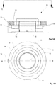
Figures 1A-1B show in a schematic manner one advantageous embodiment of a device according to the invention for producing sound and vibration, -
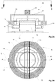
Figures 2A-2B show in a schematic manner a second advantageous embodiment of a device according to the invention for producing sound and vibration and -
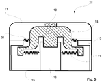
Figure 3 shows in a schematic manner a third advantageous embodiment of a device according to the invention for producing sound and vibration. - In the following description and corresponding figures, the same reference markings are used to refer to corresponding parts or part assemblies, if nothing else is mentioned. Some recurring reference markings may have been left out of the figures for the sake of clarity. In this description and the claims, terms expressing direction and/or location have been used when necessary, with reference to the examples shown in the figures and/or to facilitate understanding of the figures.
- In the advantageous example shown in
figures 1A-1B thedevice 10 for producing sound and vibration comprises aninertial actuator 16 attached on adamper mass plate 15i.e. stand 15, which inertial actuator creates the vibration transmitted to theplate 15 for producing sound and vibration. In order to produce sound, a frame of the inertial actuator has also been attached to thestand 15. The inertial actuator'sdamper mass 14 is via aprimary suspension 11 supported in a springing manner to the inertial actuator'sframe 16 to be moving substantially in the vertical direction. The power source of the inertial actuator'sdamper mass 14 is a linearly moving actuator, which can be based on an electric magnet, smart material, piezo, hydraulics, pneumatics etc. Thedevice 10 is advantageously a device as described in Finnish patent application20140019 device 10 comprises asecondary suspension 12 and amechanical limiter 13. Thesecondary suspension 12, which thus to its basic structure advantageously is a nonlinear spring structure, functions as a shock absorber and acoustic dampener by causing mechanical and acoustic losses. Themechanical limiter 13 is placed to circle the inertial actuator externally at a distance from the inertial actuator's outer surface centrally or eccentrically. Themechanical limiter 13 comprises two or more support shafts, which are placed on the outer contours at a distance from each other. The distance between two adjacent support shafts can always be the same length or different lengths. In the example shown in the figure the support shafts of themechanical limiter 13 are placed around the periphery at 120° angular spacing. The outer contours of themechanical limiter 13 in the direction can be a circle, an ellipsis, a polygon or another desired shape. Themechanical limiter 13 also comprises in the figure a horizontal support surface, on the bottom surface in the figure of which has been attached asecondary suspension 12, which is in the outer contour direction substantially continuous and is supported on the upper surface of thedamper mass 14 in the figure. Thesecondary suspension 12 is an elastic damping part, which circles the outer contour and is supported on the surface of thedamper mass 14 substantially over the entire periphery of thedamper mass 14. Advantageously, thesecondary suspension 12 is a rotationally symmetrical damping material with a thickness, which can comprise one or more damping material layers/sectors. Thesecondary suspension 12 can for example be a porous, foam-like or felt-like texture. Thesecondary suspension 12 advantageously dampens in a nonlinear, progressive manner, whereby it prevents sudden changes and achieves a to its form soft damping, and it also aids in controlling resonance frequencies, preventing e.g. resonance frequency spikes, and damping them. Thesecondary suspension 12 can be formed from one or several material layers, which are the same or different materials. The material of thesecondary suspension 12 is advantageously felt, foam polymer, batt material. It can also be a cable damper or a hydraulic or pneumatic damper. - The advantageous example of a device according to the invention for producing sound and vibration shown in
figures 2A-2B to its basic structure corresponds to the example shown infigures 1A-1B , further comprising a protective hood formed from a mechanically dampenedresonator 17, for example to protect the device from hits and/or excessive loads directed toward it in the movement direction of the damper mass, from above in the figure. The mechanical dampenedresonator 17 can also be equipped with areaction mass 18, which is for example made of steel or another solid material, for intensifying the protection. The mechanical dampenedresonator 17 is advantageously manufactured from a non-uniform structure, for example a perforated plate, stiff wire or a frame structure, which is for example made of a metallic material. - The advantageous example of a device according to the invention for producing sound and vibration shown in
figure 3 to its basic structure corresponds to the example shown infigures 1A-1B and2A-2B , comprising anadditional suspension 20 creating a springing support arranged between thedamper mass 14 and themechanical limiter 13. Additionally in this example, dampingmaterial 19 has additionally been placed between the mechanically dampenedresonator 17 anddamper mass 14, which damping material can comprise one or more damping material layers/sectors and can be for example a porous, foam-like or felt-like texture. The dampingmaterial 19 can be placed apart from thedamper mass 14 or attached to it, and can function also as a mechanical limiter in addition to thelimiter 13. - In accordance with the advantageous characteristics according to the advantageous examples shown in
figures 1A-1B ,2A-2B and3 , the device's 10 inertial actuator equipped with adamper mass 14 moving substantially in the vertical direction and forming a sound and vibration source is protected from external vibrations, hits etc. with asecondary suspension 12 and amechanical limiter 13. The protective structure formed from thesecondary suspension 12 andmechanical limiter 13 thus prevents malfunction caused by external impacts or its own resonances in the inertial actuator's movement and the vibration it creates. Themechanical limiter 13 is fitted to extend from the support shafts located on the periphery of the part providing the inertial force i.e. of the inertial actuator or as a part formed by the support shafr and it prevents an excessively large deviation of the damper mass and thus detachment of the damper mass from the structure. Advantageously the part of the device which forms the sound and vibration source is formed with a moving magnet principle to create an inertial force. The device's 10 inertial force can also be created in another manner known as such, for example using a mechanical, hydraulic or pneumatic actuator. Via themechanical limiter 13 and thesecondary suspension 12, a controlled elastic, progressive springing can be achieved for the movement of thedamper mass 14. Advantageously thedevice 10 also comprises a protective structure formed from a mechanically dampenedresonator 17, for example for protecting the device from hits and/or excessive loads directed toward it in the movement direction of the damper mass, from above in the figures. The mechanical dampenedresonator 17 can also be equipped with a dividedreaction mass 18 designed in an advantageous manner for improving vibration characteristics. The mechanical dampenedresonator 17 is advantageously manufactured from a non-uniform structure, for example a perforated plate or a frame structure. Damping material can also be added to the mechanical dampenedresonator 17, such as for example felt, foam-like polymer. The mechanical dampenedresonator 17 can also be arranged to be operationally combined with the device's 10 external wrapper, such as the perception pillow material. Theprotective structures device 10 are advantageously manufactured from a material with a low specific gravity, so that thedevice 10 is altogether light and so that the weight of the protective structures does not disturb the operation of thedamper mass plate 15. - The
device 10 according to the invention is meant to function as a vibration source over a wide frequency band of 0 - over 10 kHz. Thus, the device's 10damper mass 14 is arranged to be supported on an especially elastic mechanicalprimary suspension 11, so that particularly low frequencies are attainable. Thus, the springing of theprimary suspension 11 limits the movement of thedamper mass 14 in a desired manner while the movement of thedamper mass 14 creates vibration of thedamper mass plate 15 in a desired frequency range. Theprimary suspension 11 can also be formed from several separate suspensions arranged side-by-side and/or in layers. - The invention has been described above only with reference to one advantageous example of it, to the details of which it is however not meant to narrowly limit the invention, but many other modifications and variations are possible within the inventive idea defined by the following claims.
Claims (1)
- A device for producing sound and vibration (10) for a user to hear and feel via surface contact, which comprises a damper mass plate (15) and an inertial actuator (16) attached thereto, which inertial actuator (16) comprises a damper mass (14), which is via a primary suspension (11) supported in a springing manner on the inertial actuator (16) to be moving substantially in one linear direction, which inertial actuator comprises a power source for the damper mass (14), which device (10) comprises a secondary suspension (12) and a mechanical limiter (13), which secondary suspension (12) is attached to the mechanical limiter (13), characterized in that the secondary suspension (12) is a non-linear, elastic spring structure, which circles the inertial actuator's outer contours at a distance and is supported on the surface of the inertial actuator's damper mass (14) substantially on the outer contours of the damper mass (14), that the mechanical limiter (13) is placed to circle the inertial actuator externally at a distance from the inertial actuator's outer surface centrally or eccentrically, that the mechanical limiter (13) comprises several support shafts, which are placed on the outer contours at a distance from each other, and that the device (10) further comprises a mechanically dampened resonator (17), which is arranged to protect the device's (10) inertial actuator from hits and/or pressure load directed onto it, which mechanical dampened resonator (17) is equipped with a divided reaction mass (18) adapted to improve the vibration characteristics of the device (10).
Applications Claiming Priority (2)
| Application Number | Priority Date | Filing Date | Title |
|---|---|---|---|
| FIU20174102U FI12120U1 (en) | 2017-04-13 | 2017-04-13 | Device for producing sound and vibration |
| PCT/FI2018/050261 WO2018189422A1 (en) | 2017-04-13 | 2018-04-11 | An apparatus for producing sound and vibration |
Publications (2)
| Publication Number | Publication Date |
|---|---|
| EP3610658A1 EP3610658A1 (en) | 2020-02-19 |
| EP3610658B1 true EP3610658B1 (en) | 2021-07-07 |
Family
ID=63112802
Family Applications (1)
| Application Number | Title | Priority Date | Filing Date |
|---|---|---|---|
| EP18727341.2A Active EP3610658B1 (en) | 2017-04-13 | 2018-04-11 | An apparatus for producing sound and vibration |
Country Status (7)
| Country | Link |
|---|---|
| US (1) | US10827280B2 (en) |
| EP (1) | EP3610658B1 (en) |
| JP (2) | JP2020517182A (en) |
| KR (1) | KR102440795B1 (en) |
| CN (1) | CN110495188B (en) |
| FI (1) | FI12120U1 (en) |
| WO (1) | WO2018189422A1 (en) |
Families Citing this family (15)
| Publication number | Priority date | Publication date | Assignee | Title |
|---|---|---|---|---|
| US11689856B2 (en) | 2015-11-19 | 2023-06-27 | The Lovesac Company | Electronic furniture systems with integrated induction charger |
| US11832039B2 (en) | 2021-04-12 | 2023-11-28 | The Lovesac Company | Tuning calibration technology for systems and methods for acoustically correcting sound loss through fabric |
| US12507009B2 (en) | 2015-11-19 | 2025-12-23 | The Lovesac Company | Systems and methods for correcting sound loss through partially acoustically transparent materials |
| US12495253B2 (en) | 2015-11-19 | 2025-12-09 | The Lovesac Company | Systems and methods for tuning based on furniture configuration |
| US10212519B2 (en) | 2015-11-19 | 2019-02-19 | The Lovesac Company | Electronic furniture systems with integrated internal speakers |
| CN113727250B (en) | 2020-05-25 | 2025-05-06 | 歌尔股份有限公司 | Sound generating devices and electronic equipment |
| JP7519252B2 (en) * | 2020-10-01 | 2024-07-19 | Tdk株式会社 | Ultrasonic Transducers |
| US11977683B2 (en) * | 2021-03-12 | 2024-05-07 | Apple Inc. | Modular systems configured to provide localized haptic feedback using inertial actuators |
| US11647840B2 (en) | 2021-06-16 | 2023-05-16 | The Lovesac Company | Furniture console and methods of using the same |
| US11781941B2 (en) | 2022-01-25 | 2023-10-10 | Robert Bosch Gmbh | Multi-degree-of-freedom impedance fixture for automated frequency response function measurements |
| US12105060B2 (en) | 2022-01-25 | 2024-10-01 | Robert Bosch Gmbh | Magnetically actuated exciter device with impact function |
| US11689251B1 (en) | 2022-01-25 | 2023-06-27 | Robert Bosch Gmbh | Automated characterization of multiple-input multiple-output (MIMO) force-response problems employing subsequent single-input multiple-output (SIMO) or single-input single-output (SISO) tests with embedded instrumentation |
| US12255512B2 (en) | 2022-01-25 | 2025-03-18 | Robert Bosch Gmbh | Axial and radial suspension for a magnetically actuated exciter device |
| US12104987B2 (en) | 2022-01-25 | 2024-10-01 | Robert Bosch Gmbh | Analyzing quality of sensed force-response data during testing and mitigation poor quality output |
| US12205761B2 (en) | 2022-01-25 | 2025-01-21 | Robert Bosch Gmbh | Methods, materials and structures for manufacturing a magnetically actuated exciter device using 3D printing |
Family Cites Families (18)
| Publication number | Priority date | Publication date | Assignee | Title |
|---|---|---|---|---|
| US4641345A (en) * | 1983-10-28 | 1987-02-03 | Pioneer Electronic Corporation | Body-sensible acoustic device |
| JPS6121699A (en) * | 1984-07-10 | 1986-01-30 | Pioneer Electronic Corp | Electric vibrating transducer |
| JPS6129297A (en) * | 1984-07-19 | 1986-02-10 | Pioneer Electronic Corp | Electric oscillation transducer |
| JPH0731665Y2 (en) * | 1984-09-19 | 1995-07-19 | パイオニア株式会社 | Electromechanical vibration converter |
| JP2003125473A (en) * | 2001-10-10 | 2003-04-25 | Nec Tokin Corp | Housing case vibration piezoelectric actuator and portable electronic apparatus |
| JP4630958B2 (en) * | 2003-02-27 | 2011-02-09 | 並木精密宝石株式会社 | Multifunctional actuator and portable terminal device |
| JP4219732B2 (en) * | 2003-05-08 | 2009-02-04 | シチズン電子株式会社 | Display terminal device with panel type speaker |
| JP2004351038A (en) * | 2003-05-30 | 2004-12-16 | Yamaha Livingtec Corp | Bathroom sound system |
| CN200973173Y (en) * | 2006-11-16 | 2007-11-07 | 常州美欧电子有限公司 | Vabration acoustical generator |
| JP2009171113A (en) * | 2008-01-15 | 2009-07-30 | National Institute Of Information & Communication Technology | Variable vibration characteristic acoustic device |
| CN102119536B (en) * | 2008-07-17 | 2015-08-26 | 新传感器有限公司 | inertial vibration exciter |
| US8295538B2 (en) * | 2008-08-22 | 2012-10-23 | Harman Becker Automotive Systems Gmbh | Loudspeaker spider |
| JP5668257B2 (en) * | 2011-03-30 | 2015-02-12 | 並木精密宝石株式会社 | Multi-function vibration actuator load bearing structure |
| KR101178330B1 (en) * | 2011-06-30 | 2012-08-30 | 부산대학교 산학협력단 | Linear excitation |
| KR101320185B1 (en) * | 2012-09-19 | 2013-10-23 | 삼성전기주식회사 | Vibrating actuator |
| FI126874B (en) | 2014-01-24 | 2017-07-14 | Flexound Systems Oy | Device for the overall perception of sound |
| ITUA20163268A1 (en) * | 2015-05-22 | 2017-11-09 | Ask Ind Spa | INERTIAL ELECTRO-ACOUSTIC TRANSDUCER GROUP. |
| US9942680B1 (en) * | 2016-02-22 | 2018-04-10 | Sonos, Inc. | Transducer assembly |
-
2017
- 2017-04-13 FI FIU20174102U patent/FI12120U1/en active IP Right Grant
-
2018
- 2018-04-11 EP EP18727341.2A patent/EP3610658B1/en active Active
- 2018-04-11 CN CN201880023701.3A patent/CN110495188B/en not_active Expired - Fee Related
- 2018-04-11 US US16/603,600 patent/US10827280B2/en active Active
- 2018-04-11 WO PCT/FI2018/050261 patent/WO2018189422A1/en not_active Ceased
- 2018-04-11 KR KR1020197031549A patent/KR102440795B1/en active Active
- 2018-04-11 JP JP2019555883A patent/JP2020517182A/en active Pending
-
2023
- 2023-07-06 JP JP2023002409U patent/JP3244125U/en active Active
Also Published As
| Publication number | Publication date |
|---|---|
| JP3244125U (en) | 2023-10-13 |
| US20200045474A1 (en) | 2020-02-06 |
| US10827280B2 (en) | 2020-11-03 |
| CN110495188A (en) | 2019-11-22 |
| KR102440795B1 (en) | 2022-09-06 |
| CN110495188B (en) | 2021-05-07 |
| KR20190135019A (en) | 2019-12-05 |
| EP3610658A1 (en) | 2020-02-19 |
| JP2020517182A (en) | 2020-06-11 |
| FI12120U1 (en) | 2018-08-15 |
| WO2018189422A1 (en) | 2018-10-18 |
Similar Documents
| Publication | Publication Date | Title |
|---|---|---|
| US10827280B2 (en) | Apparatus for producing sound and vibration | |
| US11716571B2 (en) | Relating to audio transducers | |
| JP7387019B2 (en) | Sound output system, method and device | |
| JP7787605B2 (en) | earphones | |
| EP3054702B1 (en) | Speakers and headphones related to vibrations in an audio system, and methods for operating same | |
| JP4146346B2 (en) | Multi-function vibration actuator | |
| CN105745941B (en) | Bone conduction loudspeaker | |
| JPWO2019131283A1 (en) | Bone conduction speaker unit | |
| CN114765717A (en) | Loudspeaker | |
| JP4219732B2 (en) | Display terminal device with panel type speaker | |
| JP2020129843A (en) | System for bone conduction speaker | |
| CN116866767A (en) | a kind of earphone | |
| KR20090006526A (en) | Small bodily vibration vibration receiver | |
| US11407007B2 (en) | Mini subwoofer double drive low-frequency vibrator | |
| EP2241117B1 (en) | Dampening mechanism for a micro speaker | |
| CN212231315U (en) | A miniature subwoofer double driver low frequency vibrator | |
| TWI912661B (en) | Acoustic output device | |
| JP2010124030A (en) | Method of adjusting vibration noise of microphone unit | |
| JP2018207357A (en) | Electroacoustic transducer | |
| KR200382038Y1 (en) | Compact speaker unit enabling to provide surround sound | |
| HK40093810A (en) | Acoustic output devices | |
| HK40072281A (en) | Loudspeaker | |
| TW202339521A (en) | Acoustic output device | |
| KR20150014608A (en) | Piezo Actuator | |
| KR20160014447A (en) | Small sized sound receiver with vibration effect |
Legal Events
| Date | Code | Title | Description |
|---|---|---|---|
| STAA | Information on the status of an ep patent application or granted ep patent |
Free format text: STATUS: UNKNOWN |
|
| STAA | Information on the status of an ep patent application or granted ep patent |
Free format text: STATUS: THE INTERNATIONAL PUBLICATION HAS BEEN MADE |
|
| PUAI | Public reference made under article 153(3) epc to a published international application that has entered the european phase |
Free format text: ORIGINAL CODE: 0009012 |
|
| STAA | Information on the status of an ep patent application or granted ep patent |
Free format text: STATUS: REQUEST FOR EXAMINATION WAS MADE |
|
| 17P | Request for examination filed |
Effective date: 20191018 |
|
| AK | Designated contracting states |
Kind code of ref document: A1 Designated state(s): AL AT BE BG CH CY CZ DE DK EE ES FI FR GB GR HR HU IE IS IT LI LT LU LV MC MK MT NL NO PL PT RO RS SE SI SK SM TR |
|
| AX | Request for extension of the european patent |
Extension state: BA ME |
|
| DAV | Request for validation of the european patent (deleted) | ||
| DAX | Request for extension of the european patent (deleted) | ||
| GRAP | Despatch of communication of intention to grant a patent |
Free format text: ORIGINAL CODE: EPIDOSNIGR1 |
|
| STAA | Information on the status of an ep patent application or granted ep patent |
Free format text: STATUS: GRANT OF PATENT IS INTENDED |
|
| RIC1 | Information provided on ipc code assigned before grant |
Ipc: H04R 9/06 20060101AFI20210308BHEP Ipc: B06B 1/14 20060101ALI20210308BHEP Ipc: G10K 9/12 20060101ALI20210308BHEP Ipc: G10K 9/22 20060101ALI20210308BHEP |
|
| INTG | Intention to grant announced |
Effective date: 20210325 |
|
| GRAS | Grant fee paid |
Free format text: ORIGINAL CODE: EPIDOSNIGR3 |
|
| GRAA | (expected) grant |
Free format text: ORIGINAL CODE: 0009210 |
|
| STAA | Information on the status of an ep patent application or granted ep patent |
Free format text: STATUS: THE PATENT HAS BEEN GRANTED |
|
| AK | Designated contracting states |
Kind code of ref document: B1 Designated state(s): AL AT BE BG CH CY CZ DE DK EE ES FI FR GB GR HR HU IE IS IT LI LT LU LV MC MK MT NL NO PL PT RO RS SE SI SK SM TR |
|
| RAP3 | Party data changed (applicant data changed or rights of an application transferred) |
Owner name: FLEXOUND SYSTEMS OY |
|
| REG | Reference to a national code |
Ref country code: GB Ref legal event code: FG4D |
|
| REG | Reference to a national code |
Ref country code: AT Ref legal event code: REF Ref document number: 1409775 Country of ref document: AT Kind code of ref document: T Effective date: 20210715 |
|
| REG | Reference to a national code |
Ref country code: DE Ref legal event code: R096 Ref document number: 602018019738 Country of ref document: DE |
|
| REG | Reference to a national code |
Ref country code: IE Ref legal event code: FG4D |
|
| REG | Reference to a national code |
Ref country code: LT Ref legal event code: MG9D |
|
| REG | Reference to a national code |
Ref country code: NL Ref legal event code: MP Effective date: 20210707 |
|
| REG | Reference to a national code |
Ref country code: AT Ref legal event code: MK05 Ref document number: 1409775 Country of ref document: AT Kind code of ref document: T Effective date: 20210707 |
|
| PG25 | Lapsed in a contracting state [announced via postgrant information from national office to epo] |
Ref country code: HR Free format text: LAPSE BECAUSE OF FAILURE TO SUBMIT A TRANSLATION OF THE DESCRIPTION OR TO PAY THE FEE WITHIN THE PRESCRIBED TIME-LIMIT Effective date: 20210707 Ref country code: FI Free format text: LAPSE BECAUSE OF FAILURE TO SUBMIT A TRANSLATION OF THE DESCRIPTION OR TO PAY THE FEE WITHIN THE PRESCRIBED TIME-LIMIT Effective date: 20210707 Ref country code: ES Free format text: LAPSE BECAUSE OF FAILURE TO SUBMIT A TRANSLATION OF THE DESCRIPTION OR TO PAY THE FEE WITHIN THE PRESCRIBED TIME-LIMIT Effective date: 20210707 Ref country code: SE Free format text: LAPSE BECAUSE OF FAILURE TO SUBMIT A TRANSLATION OF THE DESCRIPTION OR TO PAY THE FEE WITHIN THE PRESCRIBED TIME-LIMIT Effective date: 20210707 Ref country code: RS Free format text: LAPSE BECAUSE OF FAILURE TO SUBMIT A TRANSLATION OF THE DESCRIPTION OR TO PAY THE FEE WITHIN THE PRESCRIBED TIME-LIMIT Effective date: 20210707 Ref country code: BG Free format text: LAPSE BECAUSE OF FAILURE TO SUBMIT A TRANSLATION OF THE DESCRIPTION OR TO PAY THE FEE WITHIN THE PRESCRIBED TIME-LIMIT Effective date: 20211007 Ref country code: AT Free format text: LAPSE BECAUSE OF FAILURE TO SUBMIT A TRANSLATION OF THE DESCRIPTION OR TO PAY THE FEE WITHIN THE PRESCRIBED TIME-LIMIT Effective date: 20210707 Ref country code: LT Free format text: LAPSE BECAUSE OF FAILURE TO SUBMIT A TRANSLATION OF THE DESCRIPTION OR TO PAY THE FEE WITHIN THE PRESCRIBED TIME-LIMIT Effective date: 20210707 Ref country code: NO Free format text: LAPSE BECAUSE OF FAILURE TO SUBMIT A TRANSLATION OF THE DESCRIPTION OR TO PAY THE FEE WITHIN THE PRESCRIBED TIME-LIMIT Effective date: 20211007 Ref country code: PT Free format text: LAPSE BECAUSE OF FAILURE TO SUBMIT A TRANSLATION OF THE DESCRIPTION OR TO PAY THE FEE WITHIN THE PRESCRIBED TIME-LIMIT Effective date: 20211108 Ref country code: NL Free format text: LAPSE BECAUSE OF FAILURE TO SUBMIT A TRANSLATION OF THE DESCRIPTION OR TO PAY THE FEE WITHIN THE PRESCRIBED TIME-LIMIT Effective date: 20210707 |
|
| PG25 | Lapsed in a contracting state [announced via postgrant information from national office to epo] |
Ref country code: PL Free format text: LAPSE BECAUSE OF FAILURE TO SUBMIT A TRANSLATION OF THE DESCRIPTION OR TO PAY THE FEE WITHIN THE PRESCRIBED TIME-LIMIT Effective date: 20210707 Ref country code: LV Free format text: LAPSE BECAUSE OF FAILURE TO SUBMIT A TRANSLATION OF THE DESCRIPTION OR TO PAY THE FEE WITHIN THE PRESCRIBED TIME-LIMIT Effective date: 20210707 Ref country code: GR Free format text: LAPSE BECAUSE OF FAILURE TO SUBMIT A TRANSLATION OF THE DESCRIPTION OR TO PAY THE FEE WITHIN THE PRESCRIBED TIME-LIMIT Effective date: 20211008 |
|
| REG | Reference to a national code |
Ref country code: DE Ref legal event code: R097 Ref document number: 602018019738 Country of ref document: DE |
|
| PG25 | Lapsed in a contracting state [announced via postgrant information from national office to epo] |
Ref country code: DK Free format text: LAPSE BECAUSE OF FAILURE TO SUBMIT A TRANSLATION OF THE DESCRIPTION OR TO PAY THE FEE WITHIN THE PRESCRIBED TIME-LIMIT Effective date: 20210707 |
|
| PLBE | No opposition filed within time limit |
Free format text: ORIGINAL CODE: 0009261 |
|
| STAA | Information on the status of an ep patent application or granted ep patent |
Free format text: STATUS: NO OPPOSITION FILED WITHIN TIME LIMIT |
|
| PG25 | Lapsed in a contracting state [announced via postgrant information from national office to epo] |
Ref country code: SM Free format text: LAPSE BECAUSE OF FAILURE TO SUBMIT A TRANSLATION OF THE DESCRIPTION OR TO PAY THE FEE WITHIN THE PRESCRIBED TIME-LIMIT Effective date: 20210707 Ref country code: SK Free format text: LAPSE BECAUSE OF FAILURE TO SUBMIT A TRANSLATION OF THE DESCRIPTION OR TO PAY THE FEE WITHIN THE PRESCRIBED TIME-LIMIT Effective date: 20210707 Ref country code: RO Free format text: LAPSE BECAUSE OF FAILURE TO SUBMIT A TRANSLATION OF THE DESCRIPTION OR TO PAY THE FEE WITHIN THE PRESCRIBED TIME-LIMIT Effective date: 20210707 Ref country code: EE Free format text: LAPSE BECAUSE OF FAILURE TO SUBMIT A TRANSLATION OF THE DESCRIPTION OR TO PAY THE FEE WITHIN THE PRESCRIBED TIME-LIMIT Effective date: 20210707 Ref country code: CZ Free format text: LAPSE BECAUSE OF FAILURE TO SUBMIT A TRANSLATION OF THE DESCRIPTION OR TO PAY THE FEE WITHIN THE PRESCRIBED TIME-LIMIT Effective date: 20210707 Ref country code: AL Free format text: LAPSE BECAUSE OF FAILURE TO SUBMIT A TRANSLATION OF THE DESCRIPTION OR TO PAY THE FEE WITHIN THE PRESCRIBED TIME-LIMIT Effective date: 20210707 |
|
| 26N | No opposition filed |
Effective date: 20220408 |
|
| PG25 | Lapsed in a contracting state [announced via postgrant information from national office to epo] |
Ref country code: IT Free format text: LAPSE BECAUSE OF FAILURE TO SUBMIT A TRANSLATION OF THE DESCRIPTION OR TO PAY THE FEE WITHIN THE PRESCRIBED TIME-LIMIT Effective date: 20210707 |
|
| REG | Reference to a national code |
Ref country code: CH Ref legal event code: PL |
|
| REG | Reference to a national code |
Ref country code: BE Ref legal event code: MM Effective date: 20220430 |
|
| PG25 | Lapsed in a contracting state [announced via postgrant information from national office to epo] |
Ref country code: MC Free format text: LAPSE BECAUSE OF FAILURE TO SUBMIT A TRANSLATION OF THE DESCRIPTION OR TO PAY THE FEE WITHIN THE PRESCRIBED TIME-LIMIT Effective date: 20210707 Ref country code: LU Free format text: LAPSE BECAUSE OF NON-PAYMENT OF DUE FEES Effective date: 20220411 Ref country code: LI Free format text: LAPSE BECAUSE OF NON-PAYMENT OF DUE FEES Effective date: 20220430 Ref country code: CH Free format text: LAPSE BECAUSE OF NON-PAYMENT OF DUE FEES Effective date: 20220430 |
|
| PG25 | Lapsed in a contracting state [announced via postgrant information from national office to epo] |
Ref country code: BE Free format text: LAPSE BECAUSE OF NON-PAYMENT OF DUE FEES Effective date: 20220430 |
|
| PG25 | Lapsed in a contracting state [announced via postgrant information from national office to epo] |
Ref country code: IE Free format text: LAPSE BECAUSE OF NON-PAYMENT OF DUE FEES Effective date: 20220411 |
|
| P01 | Opt-out of the competence of the unified patent court (upc) registered |
Effective date: 20230517 |
|
| PG25 | Lapsed in a contracting state [announced via postgrant information from national office to epo] |
Ref country code: MK Free format text: LAPSE BECAUSE OF FAILURE TO SUBMIT A TRANSLATION OF THE DESCRIPTION OR TO PAY THE FEE WITHIN THE PRESCRIBED TIME-LIMIT Effective date: 20210707 Ref country code: CY Free format text: LAPSE BECAUSE OF FAILURE TO SUBMIT A TRANSLATION OF THE DESCRIPTION OR TO PAY THE FEE WITHIN THE PRESCRIBED TIME-LIMIT Effective date: 20210707 |
|
| PG25 | Lapsed in a contracting state [announced via postgrant information from national office to epo] |
Ref country code: HU Free format text: LAPSE BECAUSE OF FAILURE TO SUBMIT A TRANSLATION OF THE DESCRIPTION OR TO PAY THE FEE WITHIN THE PRESCRIBED TIME-LIMIT; INVALID AB INITIO Effective date: 20180411 |
|
| PG25 | Lapsed in a contracting state [announced via postgrant information from national office to epo] |
Ref country code: TR Free format text: LAPSE BECAUSE OF FAILURE TO SUBMIT A TRANSLATION OF THE DESCRIPTION OR TO PAY THE FEE WITHIN THE PRESCRIBED TIME-LIMIT Effective date: 20210707 |
|
| PGFP | Annual fee paid to national office [announced via postgrant information from national office to epo] |
Ref country code: GB Payment date: 20240419 Year of fee payment: 7 |
|
| PGFP | Annual fee paid to national office [announced via postgrant information from national office to epo] |
Ref country code: DE Payment date: 20240419 Year of fee payment: 7 |
|
| PGFP | Annual fee paid to national office [announced via postgrant information from national office to epo] |
Ref country code: FR Payment date: 20240415 Year of fee payment: 7 |
|
| PG25 | Lapsed in a contracting state [announced via postgrant information from national office to epo] |
Ref country code: MT Free format text: LAPSE BECAUSE OF FAILURE TO SUBMIT A TRANSLATION OF THE DESCRIPTION OR TO PAY THE FEE WITHIN THE PRESCRIBED TIME-LIMIT Effective date: 20210707 |
|
| REG | Reference to a national code |
Ref country code: DE Ref legal event code: R119 Ref document number: 602018019738 Country of ref document: DE |
|
| GBPC | Gb: european patent ceased through non-payment of renewal fee |
Effective date: 20250411 |
|
| PG25 | Lapsed in a contracting state [announced via postgrant information from national office to epo] |
Ref country code: DE Free format text: LAPSE BECAUSE OF NON-PAYMENT OF DUE FEES Effective date: 20251104 |
|
| PG25 | Lapsed in a contracting state [announced via postgrant information from national office to epo] |
Ref country code: GB Free format text: LAPSE BECAUSE OF NON-PAYMENT OF DUE FEES Effective date: 20250411 |
|
| PG25 | Lapsed in a contracting state [announced via postgrant information from national office to epo] |
Ref country code: FR Free format text: LAPSE BECAUSE OF NON-PAYMENT OF DUE FEES Effective date: 20250430 |