EP3610540B1 - Igniter assembly and methods of construction thereof - Google Patents
Igniter assembly and methods of construction thereof Download PDFInfo
- Publication number
- EP3610540B1 EP3610540B1 EP18720937.4A EP18720937A EP3610540B1 EP 3610540 B1 EP3610540 B1 EP 3610540B1 EP 18720937 A EP18720937 A EP 18720937A EP 3610540 B1 EP3610540 B1 EP 3610540B1
- Authority
- EP
- European Patent Office
- Prior art keywords
- insulator
- shell
- region
- diameter
- end region
- Prior art date
- Legal status (The legal status is an assumption and is not a legal conclusion. Google has not performed a legal analysis and makes no representation as to the accuracy of the status listed.)
- Active
Links
Images



Classifications
-
- F—MECHANICAL ENGINEERING; LIGHTING; HEATING; WEAPONS; BLASTING
- F02—COMBUSTION ENGINES; HOT-GAS OR COMBUSTION-PRODUCT ENGINE PLANTS
- F02P—IGNITION, OTHER THAN COMPRESSION IGNITION, FOR INTERNAL-COMBUSTION ENGINES; TESTING OF IGNITION TIMING IN COMPRESSION-IGNITION ENGINES
- F02P23/00—Other ignition
- F02P23/04—Other physical ignition means, e.g. using laser rays
-
- H—ELECTRICITY
- H01—ELECTRIC ELEMENTS
- H01T—SPARK GAPS; OVERVOLTAGE ARRESTERS USING SPARK GAPS; SPARKING PLUGS; CORONA DEVICES; GENERATING IONS TO BE INTRODUCED INTO NON-ENCLOSED GASES
- H01T13/00—Sparking plugs
- H01T13/20—Sparking plugs characterised by features of the electrodes or insulation
- H01T13/36—Sparking plugs characterised by features of the electrodes or insulation characterised by the joint between insulation and body, e.g. using cement
-
- H—ELECTRICITY
- H01—ELECTRIC ELEMENTS
- H01T—SPARK GAPS; OVERVOLTAGE ARRESTERS USING SPARK GAPS; SPARKING PLUGS; CORONA DEVICES; GENERATING IONS TO BE INTRODUCED INTO NON-ENCLOSED GASES
- H01T13/00—Sparking plugs
- H01T13/50—Sparking plugs having means for ionisation of gap
-
- H—ELECTRICITY
- H01—ELECTRIC ELEMENTS
- H01T—SPARK GAPS; OVERVOLTAGE ARRESTERS USING SPARK GAPS; SPARKING PLUGS; CORONA DEVICES; GENERATING IONS TO BE INTRODUCED INTO NON-ENCLOSED GASES
- H01T19/00—Devices providing for corona discharge
- H01T19/04—Devices providing for corona discharge having pointed electrodes
-
- H—ELECTRICITY
- H01—ELECTRIC ELEMENTS
- H01T—SPARK GAPS; OVERVOLTAGE ARRESTERS USING SPARK GAPS; SPARKING PLUGS; CORONA DEVICES; GENERATING IONS TO BE INTRODUCED INTO NON-ENCLOSED GASES
- H01T21/00—Apparatus or processes specially adapted for the manufacture or maintenance of spark gaps or sparking plugs
-
- H—ELECTRICITY
- H01—ELECTRIC ELEMENTS
- H01T—SPARK GAPS; OVERVOLTAGE ARRESTERS USING SPARK GAPS; SPARKING PLUGS; CORONA DEVICES; GENERATING IONS TO BE INTRODUCED INTO NON-ENCLOSED GASES
- H01T21/00—Apparatus or processes specially adapted for the manufacture or maintenance of spark gaps or sparking plugs
- H01T21/02—Apparatus or processes specially adapted for the manufacture or maintenance of spark gaps or sparking plugs of sparking plugs
-
- F—MECHANICAL ENGINEERING; LIGHTING; HEATING; WEAPONS; BLASTING
- F02—COMBUSTION ENGINES; HOT-GAS OR COMBUSTION-PRODUCT ENGINE PLANTS
- F02P—IGNITION, OTHER THAN COMPRESSION IGNITION, FOR INTERNAL-COMBUSTION ENGINES; TESTING OF IGNITION TIMING IN COMPRESSION-IGNITION ENGINES
- F02P3/00—Other installations
- F02P3/01—Electric spark ignition installations without subsequent energy storage, i.e. energy supplied by an electrical oscillator
Definitions
- This invention relates generally to igniters used for igniting a fuel-air mixture in an internal combustion engine, and to the construction and method of making the insulator and shell of such igniters.
- Exemplary prior art igniters, constructions and methods can be found, i.a., in WO 2017/031390 A1 .
- Igniters for internal combustion engines are known for use in igniting an air-fuel mixture, and can include spark ignition devices and/or corona ignition devices and may include others.
- Such igniters often include an insulator of generally tubular construction which typically would house an electrode and be surrounded on the outside by steel shell which can be threaded at its lower end into a socket in the head of the engine in open communication with a combustion chamber.
- the upper end of the assembly is typically connected to a power source and the igniter operates in service to generate a controlled spark, corona discharge, plasma discharge, etc., for igniting the fuel-air mixture in the combustion chamber.
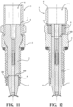
- Figures 11 and 12 illustrate igniters 1, shown as an igniter for a corona ignition system, by way of example, showing configurations of an insulator 2 and a shell 3.
- Figures 11 and 12 are used herein for explanatory purposes to assist in distinguishing inventive subject matter of the present disclosure, and are not acknowledged as being prior art.
- a "forward" assembly technique is used to assemble the insulator 2 into an upper end 4 of the shell 3
- a "reverse” assembly technique is used to assemble the insulator 2 into a lower end 5 of the shell 3.
- the corona igniter comprises an insulator surrounding a central electrode, and a shell formed of metal surrounding the insulator.
- the insulator has an insulator outer surface including an insulator intermediate region between an insulator upper end region and an insulator lower end region.
- the intermediate region has a first diameter ID 1
- the insulator upper end region has a second diameter ID2
- the insulator lower end region has a third diameter ID3.
- the second diameter ID2 and the third diameter ID3 are both greater than the first diameter D1.
- the shell has a shell outer surface including a threaded region with a plurality of threads.
- the shell also has a shell inner surface including a shell lower end region radially aligned with the threaded region.
- the shell lower end region has an inner diameter SD1 which is less than the second diameter ID2 and the third diameter ID3 of the insulator outer surface.
- the shell is also plastically deformed such that the shell inner surface conforms with the contour of the insulator intermediate region and at least a portion of the insulator upper end region, and the insulator lower end region extends axially outwardly from a shell lower end of the shell.
- a corona igniter comprising an insulator surrounding a central electrode, and a shell formed of metal surrounding the insulator.
- the insulator has an insulator outer surface including an insulator intermediate region between an insulator upper end region and an insulator lower end region.
- the insulator intermediate region has a first diameter ID1, the insulator upper end region has a second diameter ID2, and the insulator lower end region having a third diameter ID3, wherein the second diameter ID2 and the third diameter ID3 are both greater than the first diameter D1.
- the shell has a shell outer surface including a threaded region with a plurality of threads.
- the shell also has a shell inner surface including a shell lower end region radially aligned with the threaded region.
- the shell lower end region has a inner diameter which is less than the second diameter ID2 and the third diameter ID3 of the insulator outer surface.
- the shell includes separate pieces, and the shell inner surface conforms with the contour of the insulator intermediate region and at least a portion of the insulator upper end region.
- the insulator lower end region also extends axially outwardly from a shell lower end of the shell.
- Another aspect of the invention provides a method of manufacturing an igniter.
- the method comprises the steps of: providing an insulator having an insulator outer surface including an insulator intermediate region between an insulator upper end region and an insulator lower end region, the insulator intermediate region having a first diameter ID1, the insulator upper end region having a second diameter ID2, and the insulator lower end region having a third diameter ID3, wherein the second diameter ID2 and the third diameter ID3 are both greater than the first diameter D1; and inserting the insulator lower end region though a shell upper end of a shell formed of metal and past a shell lower end of the shell.
- the method further includes plastically deforming the shell such that a shell inner surface of the shell conforms with the contour of the insulator intermediate region.
- Yet another aspect of the invention provides a method of manufacturing an igniter, comprising the steps of: providing an insulator having an insulator outer surface including an insulator intermediate region between an insulator upper end region and an insulator lower end region, the insulator intermediate region having a first diameter ID1, the insulator upper end region having a second diameter ID2, and the insulator lower end region having a third diameter ID3, wherein the second diameter ID2 and the third diameter ID3 are both greater than the first diameter D1; and disposing separate pieces of a shell formed of metal around the insulator outer surface, a shell inner surface of the pieces of the shell conforming with the contour of the insulator intermediate region and at least a portion of the insulator upper end region.
- Another aspect of the invention provides method for manufacturing an igniter, comprising the steps of: providing an insulator having an insulator outer surface including an insulator intermediate region between an insulator upper end region and an insulator lower end region, the insulator intermediate region having a first diameter ID1, the insulator upper end region having a second diameter ID2, and the insulator lower end region having a third diameter ID3, wherein the second diameter ID2 and the third diameter ID3 are both greater than the first diameter D1; and casting a shell formed of metal about the insulator such that a shell inner surface of the shell conforms with the contour of the insulator intermediate region and at least a portion of the insulator upper end region, and a shell lower end of the shell is located axially above the insulator lower end region.
- FIG. 1 illustrates an igniter, shown as a corona igniter, by way of example and without limitation, referred to hereafter simply as igniter 10, constructed in accordance with one aspect of the disclosure.
- the igniter 10 includes a central electrode 12 for receiving a high radio frequency voltage, a monolithic, one-piece insulator 14 surrounding the central electrode 12, and a metal shell 16 surrounding the insulator 14.
- the central electrode 12 includes a corona-enhancing tip 18 for emitting a radio frequency electric field, sometimes referred to as "streamers", to ionize a fuel-air mixture and provide a corona discharge within a cylinder bore of an internal combustion engine.
- the metal shell 16 has an inner surface 20 bounding a through passage 22 that extends between opposite open upper and lower ends 24, 26.
- the through passage 22 has a reduced diameter region 28 through which the insulator 14 fully extends.
- the insulator 14 has an intermediate region 30 extending between opposite upper and lower end regions 32, 34.
- the upper and lower end regions 32, 34 of the insulator 14 are enlarged relative to the reduced diameter region 28 of the shell 16 such that they are prevented from being able to pass through the reduced diameter region 28 of the shell 16.
- the ignition performance, durability and useful life of the igniter 10 are enhanced without having to add additional, secondary insulative material adjacent the ends 32, 34 of the insulator 14.
- the central electrode 12 of the igniter 10 is formed of an electrically conductive material, such as a nickel alloy, for example, for receiving a voltage sufficient to cause an ignition event, and in the case of a corona-type igniter, for example, a high radio frequency voltage, typically in the range of 20 to 75 KV peak/peak, by way of example and without limitation.
- the central electrode 12 also emits energy sufficient to cause an ignition event, and in the case of a corona-type igniter, for example, a high radio frequency electric field, typically in the range of 0.9 to 1.1 MHz, again by way of example and without limitation.
- the central electrode 12 extends longitudinally along a center axis A from a terminal end 36 to an electrode firing end 38.
- the central electrode 12 typically includes the corona enhancing tip 18 at the electrode firing end 38, wherein the tip 18 includes a plurality of radially outwardly extending prongs, typically formed of nickel, nickel alloy, copper, copper alloy, iron, or iron alloy, for example.
- the insulator 14 of the corona igniter 10 is formed of an electrically insulating material, such as alumina, by way of example and without limitation.
- the insulator 14 has an inner surface 40 defines a through bore sized for receipt of the central electrode 12 therein and extends longitudinally along the center axis A from an insulator upper end 42 to an insulator lower end, also referred to as nose end 44.
- the insulator 14 has an insulator outer surface 46, wherein the outer surface 46 is typically circular, as viewed in lateral cross-section, such that the outer surface 46 has a diameter.
- the outer surface 46 extending along the insulator intermediate region 30 has a first diameter ID1 ( Figure 2 ); the outer surface 46 extending along the insulator upper end region 32 has a second diameter ID2 ( Figure 2 ); and the outer surface 46 extending along the insulator lower end region 34 has a third diameter ID3 ( Figure 2 ), wherein ID2 and ID3 are both greater than ID1.
- ID1 has a constant or substantially constant diameter extending along the full length of the intermediate region 30, by way of example and without limitation.
- the insulator outer surface 46 also includes an insulator nose region.
- the shell 16 can be formed of a plastically deformable metal material, such as steel, by way of example and without limitation.
- the shell 16 has a shell outer surface 48 facing radially outwardly and away from the axis A and extending generally along the direction of the center axis A from the shell upper end 24 to the shell lower end 26.
- the shell inner surface 20 surrounds a portion of the insulator 24, shown as surrounding the intermediate and upper end regions 30, 32, with the insulator lower end region 34 extending axially outwardly from the lower end 26 of the shell 16.
- the shell outer surface 48 has a threaded region 50 configured for threaded engagement with a threaded bore in a cylinder head of an engine (not shown).
- the threaded region 50 and a corresponding lower region 54 of the inner surface 20, radially aligned inwardly with the threaded region 50, are shown as extending from the lower end 26, or from adjacent the shell lower end 26, axially toward the upper end 24 to a radially outwardly extending shoulder 52.
- the lower region 54 of the inner surface 20 has a lower diameter SD1 ( Figure 2 ), wherein SD1 is less than ID2 and ID3. Accordingly, the outer diameters ID2, ID3 of both the upper and lower ends 42, 44 of the insulator 14 are not limited as to how large they can be by the diameter of the shell through passage 22.
- the shell shoulder 52 provides a seat for sealing abutment against a mount surface of the engine cylinder head, though it is contemplated that an annular seal member could be disposed against the shoulder 52 to perfect a seal, if desired.
- the shell 16 is plastically deformed in the threaded region 50 adjacent the shoulder 52.
- the shoulder 52 extends radially outwardly and transitions into an axially extending enlarged region 56 of the outer surface 48, wherein an upper region 58 of the shell inner surface 20, extending opposite and generally parallel with the enlarged region 56, flares radially outwardly to provide a upper diameter SD2 ( Figure 2 ), wherein SD2 is greater than ID2.
- the enlarged diameter regions 56, 58 are shown as extending to the shell upper end 24.
- at least a portion of the outer surface enlarged region 56 can be formed having a tool receiving section 60, such as a hexagonal shaped region, for example.
- the insulator 14 is provided as a single piece of insulative material having the desired finish shape, such as shown in Figure 3 , by way of example and without limitation.
- the finish shape includes upper and lower end regions 32, 34 having respective portions with outer diameters ID2, ID3 spaced axially from one another by an intermediate region 30 having a outer diameter ID1, wherein the identified outer diameters ID2, ID3 of the upper and lower end regions 32, 34 are greater than the outer diameter ID1 of the intermediate region 30.
- the finish shape includes upper and lower end regions 32, 34 having respective portions with outer diameters ID2, ID3 spaced axially from one another by an intermediate region 30 having a outer diameter ID1, wherein the identified outer diameters ID2, ID3 of the upper and lower end regions 32, 34 are greater than the outer diameter ID1 of the intermediate region 30.
- the metal shell 16 can be provided in the initial stage of construction as a single piece of metal material having a tubular body 62 with a circumferentially continuous, seamless wall 63 with an inner surface 20 bounding a through passage 22 that extends between opposite upper and lower ends 24, 26.
- the metal shell 16, at the initial stage can also have a ductile nickel plating deposited thereon to enhance corrosion resistance and to facilitate a downstream braze sealing process, wherein the plating is durable enough to withstand subsequent forming process steps.
- annular gasket or seal material 64 can be disposed in a counterbore recess 66 in the lower end 26 of the shell 16 to facilitate the formation of a hermetic seal between the insulator 14 and shell 16.
- the through passage 22 is enlarged at an upper region 58, extending from the upper end 24 toward the lower end 26, relative to a lower region 54 adjacent the lower end 26.
- the enlarged upper region 58 of the through passage 22 is sized to receive the upper end region 32 of the insulator therein and the lower end region 34 therethrough, such as in a forward assembly process, while the lower region 54 is shown initially sized having a reduced inner diameter relative to the upper region 58, yet enlarged relative to a finished state so as to enable the lower end region 34 of the insulator 14 to be inserted therethrough.
- a braze material can be disposed between a select region or regions of the insulator and shell 16 for subsequent brazing to further promote forming a hermetic seal between the insulator 14 and shell 16.
- at least the region of the insulator 14 where brazing is performed can be metalized.
- the shell 16 is plastically deformed in a forming operation to substantially conform the shell inner surface 20 with the contour of the insulator outer surface 46, leaving annular gaps where desired to inhibit arcing.
- the forming operation can be performed via one of a plurality of metal forming processes, including, by way of example and without limitation, a cold forming process, such as swaging, extruding, crimping, rolling and end forming, or via a magnetic pulse forming process, also referred to as electromagnetic forming (EM forming) or magneforming, for example.
- a cold forming process such as swaging, extruding, crimping, rolling and end forming
- EM forming magnetic pulse forming
- magneforming magnetic pulse forming
- the insulator 14 upon forming the single piece metal shell 16 about the single piece insulator 14, the insulator 14 is permanently fixed against being removed axially outwardly from the shell 16 as a result of the upper end region 32 and the lower end region 34 both having diameters D2, D3 larger than the inner diameter SD1 within the shell lower region 54.
- the enlarged lower end region 34 is shaped as an annular flange that extends radially outwardly beyond the shell inner surface 20 to substantially confront the shell lower end 26 and constrain the gasket 64 against removal. It is to be understood that other shapes of the enlarged lower end region 34 than that shown are contemplated herein.
- forming and/or machining processes can be performed, including forming threads in a thread rolling or thread cutting operation, whereby a threaded region 50 can be formed for threaded engagement with a corresponding threaded opening in a cylinder head. Additional threaded regions can also be formed, such as along the outer surface 48 or inner surface 20 adjacent the shell upper end 24, for example, depending on the intended application requirements. It is to be recognized that the forming and/or machining operations do not cause mechanical stress to, or otherwise damage, the insulator 14 or various coatings when performed by those skilled in the art in view of the teachings herein.
- additional processes can be performed, including: performing a brazing process in a braze furnace, thereby establishing desired hermetic seals between the insulator 14 and the shell 16; installing an igniter core assembly 68 within a through bore 70 of the insulator 14, including a central electrode 12 and further assembling a corona enhancing tip 18, if constructing a corona-type igniter, to the end of the central electrode 12, if not previously installed.
- the metal shell 16 can be provided in the initial stage of construction as a plurality of separate pieces of metal material, including separate halves 70, 72, by way of example and without limitation.
- the separate pieces can be coated, at least in part, with a corrosion resistant layer of nickel or other suitable material, as discussed above.
- the separate halves 70, 72 are configured to be joined together to form a tubular body 62 having a circumferentially continuous wall 63, with an inner surface 20 bounding a through passage 22 sized for receipt of the insulator 14 therein.
- a cold forming process to conform the shell 16 about the insulator 14 is not necessary, as the shell pieces 70, 72 can be pre-shaped and sized to provide the desired finish fit about the insulator 14 upon being fixed thereabout.
- a further shell piece 73 shown as being tubular, can be provided to form the upper end 24 and enlarged diameter region 60, if desired. It is contemplated herein that the separate halves 70, 72 could be configured to form the entirety of the shell 16, including the upper enlarged diameter region 56, if desired; however, it is contemplated that material savings may be attained by forming the enlarged diameter region 56 from a separate piece of metal tubing.
- the separate pieces 70, 72 can be fixed to one another via weld seams 74 in a welding operation, such as a laser welding operation, by way of example and without limitation.
- a welding operation such as a laser welding operation
- the enlarged diameter tubular region 56 can be brought into concentrically aligned abutment with the welded, reduced diameter region 28, shown as being disposed in part about an outer surface of the welded, reduced diameter region 28, and then welded thereto via an annular weld joint 76, such as laser weld joint.
- FIG. 6 is a cross-sectional view of the insulator and shell after the welding step.
- FIGS 7A-7C another method 300 is illustrated showing steps of constructing an igniter 10 in accordance with another aspect of the invention.
- the method 300 is similar to the method 200; however, a central electrode assembly, including a central electrode 12 and firing tip 18, are disposed within an insulator 14 prior to disposing the shell 16 thereabout. Otherwise, the process is the same as discussed above for the process illustrated in Figures 5A-5E .
- the metal shell can be cast about the insulator, and upon casting, any desired secondary operations, can be performed, such as thread forming, if not already cast into the shell.
Landscapes
- Engineering & Computer Science (AREA)
- Manufacturing & Machinery (AREA)
- Physics & Mathematics (AREA)
- Optics & Photonics (AREA)
- Chemical & Material Sciences (AREA)
- Combustion & Propulsion (AREA)
- Mechanical Engineering (AREA)
- General Engineering & Computer Science (AREA)
- Plasma & Fusion (AREA)
- Spark Plugs (AREA)
Description
- This U.S. Utility Patent Application claims priority to
U.S. Provisional Patent Application Serial No. 62/484,364, filed April 11, 2017 U.S. Utility Provisional Application Serial No. 15/949,296, filed April 10, 2018 - This invention relates generally to igniters used for igniting a fuel-air mixture in an internal combustion engine, and to the construction and method of making the insulator and shell of such igniters. Exemplary prior art igniters, constructions and methods can be found, i.a., in
WO 2017/031390 A1 . - Igniters for internal combustion engines are known for use in igniting an air-fuel mixture, and can include spark ignition devices and/or corona ignition devices and may include others. Such igniters often include an insulator of generally tubular construction which typically would house an electrode and be surrounded on the outside by steel shell which can be threaded at its lower end into a socket in the head of the engine in open communication with a combustion chamber. The upper end of the assembly is typically connected to a power source and the igniter operates in service to generate a controlled spark, corona discharge, plasma discharge, etc., for igniting the fuel-air mixture in the combustion chamber.
-
Figures 11 and 12 illustrate igniters 1, shown as an igniter for a corona ignition system, by way of example, showing configurations of aninsulator 2 and ashell 3.Figures 11 and 12 are used herein for explanatory purposes to assist in distinguishing inventive subject matter of the present disclosure, and are not acknowledged as being prior art. InFigure 11 , a "forward" assembly technique is used to assemble theinsulator 2 into an upper end 4 of theshell 3, while inFigure 12 , a "reverse" assembly technique is used to assemble theinsulator 2 into alower end 5 of theshell 3. In both cases, the portion of theinsulator 2 that is being inserted through athrough passage 6 of theshell 3 has an insulator diameter (ID) that is less than a shell diameter (SD) of thethrough passage 6. This naturally limits the size of the insertion end of theinsulator 2 since it must fit through the opening in theshell 3. Prior art documentUS 2016/0359302 A2 is likewise exemplary of the "forward" and "reverse" assembly techniques, as well as the insulator construction, referred to above. - In some ignition applications, it has been found advantageous for ignition performance and durability to have the
insulator 2 larger than the diameter of the shell throughpassage 6, and thus, designers must presently decide which end of theinsulator 2 to provide a relatively enlarged end, while leaving the opposite end having a reduced diameter sufficient to pass through the diameter of the shell throughpassage 6. If performing a forward assembly technique, an upper end of theinsulator 2 can be provided having an enlarged end 7 (Figure 11 ), and if performing a reverse assembly technique, a lower end of theinsulator 2 can be provided having an enlarged end 8 (Figure 12 ). In either case, the end opposite the enlargedend 7, 8 must remain sufficiently small to be able to be inserted through the diameter of the throughpassage 6. Attempts have been made to add secondary enlarging insulating components 9 to the relatively small end of theinsulator 2, and although met with some success, improvements in both performance and durability are desired. Some drawbacks typically occur due the high electrical, mechanical, and thermal stresses placed on the joint between theinsulator 2 and the secondary enlarging insulating components 9, thereby resulting in a less than optimal ignition event, thereby resulting in a less than optimal performance. Further yet, the joint between theinsulator 2 and second component 9 lends itself to corrosion, separation and failure, thereby resulting in a less than optimal durability. Further yet, having to perform secondary operations to incorporate secondary components adds complexity and cost to the process and the igniter. - One aspect of the invention provides a corona igniter. The corona igniter comprises an insulator surrounding a central electrode, and a shell formed of metal surrounding the insulator. The insulator has an insulator outer surface including an insulator intermediate region between an insulator upper end region and an insulator lower end region. The intermediate region has a first diameter ID 1, the insulator upper end region has a second diameter ID2, and the insulator lower end region has a third diameter ID3. The second diameter ID2 and the third diameter ID3 are both greater than the first diameter D1. The shell has a shell outer surface including a threaded region with a plurality of threads. The shell also has a shell inner surface including a shell lower end region radially aligned with the threaded region. The shell lower end region has an inner diameter SD1 which is less than the second diameter ID2 and the third diameter ID3 of the insulator outer surface. The shell is also plastically deformed such that the shell inner surface conforms with the contour of the insulator intermediate region and at least a portion of the insulator upper end region, and the insulator lower end region extends axially outwardly from a shell lower end of the shell.
- Another aspect of the invention provides a corona igniter comprising an insulator surrounding a central electrode, and a shell formed of metal surrounding the insulator. The insulator has an insulator outer surface including an insulator intermediate region between an insulator upper end region and an insulator lower end region. The insulator intermediate region has a first diameter ID1, the insulator upper end region has a second diameter ID2, and the insulator lower end region having a third diameter ID3, wherein the second diameter ID2 and the third diameter ID3 are both greater than the first diameter D1. The shell has a shell outer surface including a threaded region with a plurality of threads. The shell also has a shell inner surface including a shell lower end region radially aligned with the threaded region. The shell lower end region has a inner diameter which is less than the second diameter ID2 and the third diameter ID3 of the insulator outer surface. The shell includes separate pieces, and the shell inner surface conforms with the contour of the insulator intermediate region and at least a portion of the insulator upper end region. The insulator lower end region also extends axially outwardly from a shell lower end of the shell.
- Another aspect of the invention provides a method of manufacturing an igniter. The method comprises the steps of: providing an insulator having an insulator outer surface including an insulator intermediate region between an insulator upper end region and an insulator lower end region, the insulator intermediate region having a first diameter ID1, the insulator upper end region having a second diameter ID2, and the insulator lower end region having a third diameter ID3, wherein the second diameter ID2 and the third diameter ID3 are both greater than the first diameter D1; and inserting the insulator lower end region though a shell upper end of a shell formed of metal and past a shell lower end of the shell. The method further includes plastically deforming the shell such that a shell inner surface of the shell conforms with the contour of the insulator intermediate region.
- Yet another aspect of the invention provides a method of manufacturing an igniter, comprising the steps of: providing an insulator having an insulator outer surface including an insulator intermediate region between an insulator upper end region and an insulator lower end region, the insulator intermediate region having a first diameter ID1, the insulator upper end region having a second diameter ID2, and the insulator lower end region having a third diameter ID3, wherein the second diameter ID2 and the third diameter ID3 are both greater than the first diameter D1; and disposing separate pieces of a shell formed of metal around the insulator outer surface, a shell inner surface of the pieces of the shell conforming with the contour of the insulator intermediate region and at least a portion of the insulator upper end region.
- Another aspect of the invention provides method for manufacturing an igniter, comprising the steps of: providing an insulator having an insulator outer surface including an insulator intermediate region between an insulator upper end region and an insulator lower end region, the insulator intermediate region having a first diameter ID1, the insulator upper end region having a second diameter ID2, and the insulator lower end region having a third diameter ID3, wherein the second diameter ID2 and the third diameter ID3 are both greater than the first diameter D1; and casting a shell formed of metal about the insulator such that a shell inner surface of the shell conforms with the contour of the insulator intermediate region and at least a portion of the insulator upper end region, and a shell lower end of the shell is located axially above the insulator lower end region.
- These and other features and advantages will become readily apparent to those skilled in the art in view of the following detailed description of the presently preferred embodiments and best mode, appended claims, and accompanying drawings, in which:
-
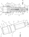
Figure 1 is a perspective view of an igniter in accordance with one aspect of the invention; -
Figure 2 is a cross-sectional view of the igniter ofFigure 1 ; -
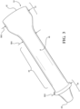
Figure 3 is a perspective view of an insulator shown in accordance with a further aspect of the invention; -
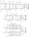
Figures 4A-4C illustrate steps used to construct an igniter in accordance with a further aspect of the invention; -
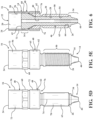
Figures 5A-5E illustrate steps used to construct an igniter in accordance with further examples; -
Figure 6 is a cross-sectional view illustrating a shell and insulator assembly upon completing the construction steps ofFigures 5A-5E ; -
Figures 7A-7C illustrate cross-sectional views of an igniter being constructed in accordance with the steps similar to those illustratedFigures 5A-5E in accordance with yet a further aspect of the invention, with a central electrode assembly disposed in the insulator throughout the construction steps; -
Figures 8-10 illustrate cross-sectional views of different igniters constructed in accordance further aspects of the invention; and -
Figures 11 and 12 illustrate igniters that are not in accordance with the invention, but rather, identify issues and problems that the current invention resolves. - Referring in more detail to the drawings,
Figure 1 illustrates an igniter, shown as a corona igniter, by way of example and without limitation, referred to hereafter simply asigniter 10, constructed in accordance with one aspect of the disclosure. Theigniter 10 includes acentral electrode 12 for receiving a high radio frequency voltage, a monolithic, one-piece insulator 14 surrounding thecentral electrode 12, and ametal shell 16 surrounding theinsulator 14. Thecentral electrode 12 includes a corona-enhancingtip 18 for emitting a radio frequency electric field, sometimes referred to as "streamers", to ionize a fuel-air mixture and provide a corona discharge within a cylinder bore of an internal combustion engine. Themetal shell 16 has aninner surface 20 bounding a throughpassage 22 that extends between opposite open upper andlower ends passage 22 has a reduceddiameter region 28 through which theinsulator 14 fully extends. Theinsulator 14 has anintermediate region 30 extending between opposite upper andlower end regions lower end regions insulator 14 are enlarged relative to the reduceddiameter region 28 of theshell 16 such that they are prevented from being able to pass through the reduceddiameter region 28 of theshell 16. As will be appreciated by one skilled in the art, with the one-piece insulator 14 having enlarged, generally bulbous upper andlower end regions igniter 10 are enhanced without having to add additional, secondary insulative material adjacent theends insulator 14. - The
central electrode 12 of theigniter 10 is formed of an electrically conductive material, such as a nickel alloy, for example, for receiving a voltage sufficient to cause an ignition event, and in the case of a corona-type igniter, for example, a high radio frequency voltage, typically in the range of 20 to 75 KV peak/peak, by way of example and without limitation. Thecentral electrode 12 also emits energy sufficient to cause an ignition event, and in the case of a corona-type igniter, for example, a high radio frequency electric field, typically in the range of 0.9 to 1.1 MHz, again by way of example and without limitation. Thecentral electrode 12 extends longitudinally along a center axis A from aterminal end 36 to anelectrode firing end 38. Thecentral electrode 12 typically includes thecorona enhancing tip 18 at theelectrode firing end 38, wherein thetip 18 includes a plurality of radially outwardly extending prongs, typically formed of nickel, nickel alloy, copper, copper alloy, iron, or iron alloy, for example. - The
insulator 14 of thecorona igniter 10 is formed of an electrically insulating material, such as alumina, by way of example and without limitation. Theinsulator 14 has aninner surface 40 defines a through bore sized for receipt of thecentral electrode 12 therein and extends longitudinally along the center axis A from an insulatorupper end 42 to an insulator lower end, also referred to asnose end 44. Theinsulator 14 has an insulatorouter surface 46, wherein theouter surface 46 is typically circular, as viewed in lateral cross-section, such that theouter surface 46 has a diameter. Theouter surface 46 extending along the insulatorintermediate region 30 has a first diameter ID1 (Figure 2 ); theouter surface 46 extending along the insulatorupper end region 32 has a second diameter ID2 (Figure 2 ); and theouter surface 46 extending along the insulatorlower end region 34 has a third diameter ID3 (Figure 2 ), wherein ID2 and ID3 are both greater than ID1. In the embodiment shown, ID1 has a constant or substantially constant diameter extending along the full length of theintermediate region 30, by way of example and without limitation. The insulatorouter surface 46 also includes an insulator nose region. - The
shell 16 can be formed of a plastically deformable metal material, such as steel, by way of example and without limitation. Theshell 16 has a shellouter surface 48 facing radially outwardly and away from the axis A and extending generally along the direction of the center axis A from the shellupper end 24 to the shelllower end 26. The shellinner surface 20 surrounds a portion of theinsulator 24, shown as surrounding the intermediate andupper end regions lower end region 34 extending axially outwardly from thelower end 26 of theshell 16. The shellouter surface 48 has a threadedregion 50 configured for threaded engagement with a threaded bore in a cylinder head of an engine (not shown). The threadedregion 50 and a correspondinglower region 54 of theinner surface 20, radially aligned inwardly with the threadedregion 50, are shown as extending from thelower end 26, or from adjacent the shelllower end 26, axially toward theupper end 24 to a radially outwardly extendingshoulder 52. Thelower region 54 of theinner surface 20 has a lower diameter SD1 (Figure 2 ), wherein SD1 is less than ID2 and ID3. Accordingly, the outer diameters ID2, ID3 of both the upper and lower ends 42, 44 of theinsulator 14 are not limited as to how large they can be by the diameter of the shell throughpassage 22. - The
shell shoulder 52 provides a seat for sealing abutment against a mount surface of the engine cylinder head, though it is contemplated that an annular seal member could be disposed against theshoulder 52 to perfect a seal, if desired. In some example embodiments, theshell 16 is plastically deformed in the threadedregion 50 adjacent theshoulder 52. Theshoulder 52 extends radially outwardly and transitions into an axially extendingenlarged region 56 of theouter surface 48, wherein anupper region 58 of the shellinner surface 20, extending opposite and generally parallel with theenlarged region 56, flares radially outwardly to provide a upper diameter SD2 (Figure 2 ), wherein SD2 is greater than ID2. Theenlarged diameter regions upper end 24. To facilitate fastening theigniter 10 to the cylinder head of the engine, at least a portion of the outer surface enlargedregion 56 can be formed having atool receiving section 60, such as a hexagonal shaped region, for example. - In construction of the
igniter 10, theinsulator 14 is provided as a single piece of insulative material having the desired finish shape, such as shown inFigure 3 , by way of example and without limitation. Regardless of particular details of the finish shape which can be altered for different engine applications, the finish shape includes upper andlower end regions intermediate region 30 having a outer diameter ID1, wherein the identified outer diameters ID2, ID3 of the upper andlower end regions intermediate region 30. It will be recognized by one skilled in the art that within thespecific regions Figures 8-10 illustratingigniters - In
Figures 4A-4C , one method 100 is illustrated showing steps of constructing anigniter 10 in accordance with one aspect of the invention. As illustrated inFigure 4A , themetal shell 16 can be provided in the initial stage of construction as a single piece of metal material having atubular body 62 with a circumferentially continuous,seamless wall 63 with aninner surface 20 bounding a throughpassage 22 that extends between opposite upper and lower ends 24, 26. Themetal shell 16, at the initial stage, can also have a ductile nickel plating deposited thereon to enhance corrosion resistance and to facilitate a downstream braze sealing process, wherein the plating is durable enough to withstand subsequent forming process steps. Further yet, an annular gasket orseal material 64 can be disposed in acounterbore recess 66 in thelower end 26 of theshell 16 to facilitate the formation of a hermetic seal between theinsulator 14 andshell 16. As shown inFigure 4A , the throughpassage 22 is enlarged at anupper region 58, extending from theupper end 24 toward thelower end 26, relative to alower region 54 adjacent thelower end 26. The enlargedupper region 58 of the throughpassage 22 is sized to receive theupper end region 32 of the insulator therein and thelower end region 34 therethrough, such as in a forward assembly process, while thelower region 54 is shown initially sized having a reduced inner diameter relative to theupper region 58, yet enlarged relative to a finished state so as to enable thelower end region 34 of theinsulator 14 to be inserted therethrough. - Upon or during disposing the
insulator 14 into theshell 16, a braze material can be disposed between a select region or regions of the insulator andshell 16 for subsequent brazing to further promote forming a hermetic seal between theinsulator 14 andshell 16. To facilitate brazing, at least the region of theinsulator 14 where brazing is performed can be metalized. Then, as shown inFigure 4B , theshell 16 is plastically deformed in a forming operation to substantially conform the shellinner surface 20 with the contour of the insulatorouter surface 46, leaving annular gaps where desired to inhibit arcing. The forming operation can be performed via one of a plurality of metal forming processes, including, by way of example and without limitation, a cold forming process, such as swaging, extruding, crimping, rolling and end forming, or via a magnetic pulse forming process, also referred to as electromagnetic forming (EM forming) or magneforming, for example. Regardless of the forming process used, upon forming the singlepiece metal shell 16 about thesingle piece insulator 14, theinsulator 14 is permanently fixed against being removed axially outwardly from theshell 16 as a result of theupper end region 32 and thelower end region 34 both having diameters D2, D3 larger than the inner diameter SD1 within the shelllower region 54. As can be seen inFigure 4B , the enlargedlower end region 34 is shaped as an annular flange that extends radially outwardly beyond the shellinner surface 20 to substantially confront the shelllower end 26 and constrain thegasket 64 against removal. It is to be understood that other shapes of the enlargedlower end region 34 than that shown are contemplated herein. - Upon forming the
shell body 62 about theinsulator 14, further forming and/or machining processes can be performed, including forming threads in a thread rolling or thread cutting operation, whereby a threadedregion 50 can be formed for threaded engagement with a corresponding threaded opening in a cylinder head. Additional threaded regions can also be formed, such as along theouter surface 48 orinner surface 20 adjacent the shellupper end 24, for example, depending on the intended application requirements. It is to be recognized that the forming and/or machining operations do not cause mechanical stress to, or otherwise damage, theinsulator 14 or various coatings when performed by those skilled in the art in view of the teachings herein. - Upon forming the
shell 16 and features thereon, additional processes can be performed, including: performing a brazing process in a braze furnace, thereby establishing desired hermetic seals between theinsulator 14 and theshell 16; installing anigniter core assembly 68 within a throughbore 70 of theinsulator 14, including acentral electrode 12 and further assembling acorona enhancing tip 18, if constructing a corona-type igniter, to the end of thecentral electrode 12, if not previously installed. - It is to be recognized that although a forward installation process is discussed above with regard to
Figures 4A-4C (inserting theinsulator 14 into theupper end 24 of the shell 16), that a reverse installation process is contemplated herein (inserting theinsulator 14 into thelower end 26 of the shell 16), wherein the respective diameters of the upper andlower end regions upper end region 32 of theinsulator 14 can be provided having a smaller or equal diameter ID2 relative to the diameter ID3 of thelower end region 34, but yet still being larger than the diameter ID1 of theintermediate region 30. - In
Figures 5A-5E , another method 200 is illustrated showing steps of constructing anigniter 10 in accordance with other examples. As illustrated inFigure 5A , themetal shell 16 can be provided in the initial stage of construction as a plurality of separate pieces of metal material, includingseparate halves separate halves tubular body 62 having a circumferentiallycontinuous wall 63, with aninner surface 20 bounding a throughpassage 22 sized for receipt of theinsulator 14 therein. Unlike the embodiment illustrated inFigures 4A-4C , a cold forming process to conform theshell 16 about theinsulator 14 is not necessary, as theshell pieces insulator 14 upon being fixed thereabout. In addition to the shell halves 70, 72, afurther shell piece 73, shown as being tubular, can be provided to form theupper end 24 andenlarged diameter region 60, if desired. It is contemplated herein that theseparate halves shell 16, including the upperenlarged diameter region 56, if desired; however, it is contemplated that material savings may be attained by forming theenlarged diameter region 56 from a separate piece of metal tubing. - As shown in
Figure 5B , upon assembling thepieces shell 16 about theintermediate region 30 of theinsulator 14, wherein theaforementioned gasket 64 can also be inserted, theseparate pieces Figure 5C , if provided as a separate piece, the enlarged diametertubular region 56 can be brought into concentrically aligned abutment with the welded, reduceddiameter region 28, shown as being disposed in part about an outer surface of the welded, reduceddiameter region 28, and then welded thereto via an annular weld joint 76, such as laser weld joint. Thereafter, the same processes can be performed as discussed above for the single piece shell, namely, brazing (wherein a surface of the insulator can be metallized to facilitate forming a reliable braze), plating, thread forming, including forming a threadedregion 50 for fixation to the cylinder head, and elsewhere, as needed.Figure 6 is a cross-sectional view of the insulator and shell after the welding step. - In
Figures 7A-7C , another method 300 is illustrated showing steps of constructing anigniter 10 in accordance with another aspect of the invention. The method 300 is similar to the method 200; however, a central electrode assembly, including acentral electrode 12 and firingtip 18, are disposed within aninsulator 14 prior to disposing theshell 16 thereabout. Otherwise, the process is the same as discussed above for the process illustrated inFigures 5A-5E . - In accordance with yet another aspect of the invention, the metal shell can be cast about the insulator, and upon casting, any desired secondary operations, can be performed, such as thread forming, if not already cast into the shell.
Claims (13)
- A corona igniter (10), comprising:an insulator (14) surrounding a central electrode (12), the insulator (14) being provided as a single piece of insulative material and having an intermediate region extending between opposite upper (32) and lower (34) end regions;said insulator (14) having an insulator outer surface (46), the outer surface extending along the insulator intermediate (30) region, along the insulator upper end region (32) and along the insulator lower end region (34);the insulator outer surface (46) extending along said insulator intermediate region having a first diameter ID1, the insulator outer surface (46) extending along said insulator upper end region (32) having a second diameter ID2, and the insulator outer surface (46) extending along said insulator lower end region (34) having a third diameter ID3, wherein said second diameter ID2 and said third diameter ID3 are both greater than said first diameter ID 1;a shell (16) formed of metal surrounding said insulator (14);said shell (16) having a shell outer surface (48) including a threaded region (50) with a plurality of threads;said shell (16) having a shell inner surface (20) including a shell lower end region radially aligned with said threaded region (50);said shell lower end region having an inner diameter SD1 which is less than said second diameter ID2 and said third diameter ID3 of said insulator outer surface (46);said shell (16) being plastically deformed such that said shell inner surface (20) conforms with the contour of said insulator intermediate region (30); andsaid insulator lower end region (34) extending axially outwardly from a shell lower end (26) of said shell (16).
- A corona igniter (10) according to claim 1, wherein said insulator outer surface (46) includes an insulator nose region extending continuously and tapering from said insulator lower end region (34) to an insulator nose end.
- A corona igniter (10) according to claim 1, wherein said insulator upper end region (32) presents a bulbous shape, said first diameter ID1 of said insulator intermediate region (30) is constant and extends continuously from said insulator upper end region (32) to said insulator lower end region (34), said third diameter ID3 of said insulator lower end region (34) is constant, and said insulator outer surface (46) includes an insulator nose region extending continuously and tapering from said insulator lower end region (34) to an insulator nose end.
- A corona igniter (10) according to claim 1, wherein said threaded region (50) of said shell outer surface (48) extends axially to a shell shoulder (52), said shell shoulder (52) provides a seat for sealing abutment against a mount surface of an engine cylinder head.
- A corona igniter (10) according to claim 4, wherein said shell (16) is plastically deformed along said threaded region (50) adjacent said shell shoulder (52).
- A corona igniter (10) according to claim 1, wherein said insulator (14) is permanently fixed against being removed axially outwardly from said shell (16).
- A corona igniter (10) according to claim 1, including a braze, sealing material, and/or gasket providing a hermetic seal between said insulator outer surface (46) and said shell inner surface (20).
- A corona igniter (10) according to claim 1, wherein said central electrode (12) is formed of an electrically conductive material for receiving a high radio frequency voltage;said central electrode (12) extends longitudinally along a center axis (A) from a terminal end (36) to an electrode firing end (38);said central electrode (12) includes a corona-enhancing tip (18) for emitting a radio frequency electric field in a range of 0.9 to 1.1 MHz;said corona enhancing tip (18) includes a plurality of radially outwardly extending prongs;said prongs are formed of nickel, nickel alloy, copper, copper alloy, iron, or iron alloy;said insulator (14) is a monolithic piece of electrically insulating material extending longitudinally from an insulator upper end (42) to an insulator nose end (44);said insulator outer surface (46) includes an insulator nose region extending continuously and tapering from said insulator lower end region to said insulator nose end;said first diameter ID1 of said insulator intermediate region (30) is constant and extends continuously from said insulator upper end region (32) to said insulator lower end region (34);said insulator upper end region (32) presents a bulbous shape;said first diameter ID1 extending along said insulator intermediate region (30) is constant;said third diameter ID3 of said insulator lower end region (42) is constant;said insulator inner surface (40) defines a through bore receiving said central electrode (12) therein;said through bore extends longitudinally along said center axis (A) from said insulator upper end to said insulator nose end;said metal of said shell (16) is steel, said steel is plastically deformable;said shell outer surface faces radially outwardly and away from said center axis from a shell upper end (24) to a shell lower end (26);said shell inner surface (20) surrounds said insulator intermediate (30) and upper end regions (32);said insulator lower end region (34) extends axially outwardly from said shell lower end (26);said threaded region (50) of said shell extends axially to a shell shoulder (52);said shell shoulder (52) provides a seat for sealing abutment against a mount surface of an engine cylinder head;said shoulder (52) extends radially outwardly and transitions into an axially extending enlarged region of said shell outer surface (48);said shell (16) is plastically deformed along said threaded region (50) adjacent said shoulder (52);said shell inner surface (20) includes a shell upper region (58) extending opposite said enlarged region (56) of said shell outer surface (48);said shell upper region (58) extends radially outwardly to provide an upper diameter SD2;said upper diameter SD2 is greater than said second diameter ID2 of said insulator outer surface (46);said insulator (14) is permanently fixed against being removed axially outwardly from the shell (16); anda braze, sealing material, and/or gasket provides a hermetic seal between said insulator outer surface (46) and said shell inner surface (20).
- A method of manufacturing an igniter according to Claim 1, comprising the steps of:providing an insulator (14) as a single piece of insulative material and having an intermediate region extending between opposite upper (32) and lower (34) end regions, the insulator (14) having an insulator outer surface (46) extending along the insulator intermediate region (30) between an insulator upper end region (32) and an insulator lower end region (34), and having a first diameter ID1, the insulator outer surface (46) extending along the insulator upper end region (32) having a second diameter ID2, and the insulator outer surface extending along the insulator lower end region (34) having a third diameter ID3, wherein the second diameter ID2 and the third diameter ID3 are both greater than the first diameter ID1;inserting the insulator lower end region (34) though a shell upper end (24) of a shell formed of metal and past a shell lower end of the shell; andplastically deforming the shell (16) such that a shell inner surface (20) of the shell (16) conforms with the contour of the insulator intermediate region (30).
- A method according to claim 9, wherein the plastically deforming step includes a cold forming process or a magnetic pulse forming process.
- A method according to claim 9, wherein the insulator lower end region (34) extends axially outwardly from a shell lower end (26) of the shell (16).
- A method according to claim 11 including brazing the insulator (14) to the shell (16).
- A method according to claim 11, wherein the step of disposing the shell (16) around the insulator (14) includes disposing a shell lower end of the shell axially above the insulator lower end region (34).
Applications Claiming Priority (3)
| Application Number | Priority Date | Filing Date | Title |
|---|---|---|---|
| US201762484364P | 2017-04-11 | 2017-04-11 | |
| US15/949,296 US10578073B2 (en) | 2017-04-11 | 2018-04-10 | Igniter assembly, insulator therefor and methods of construction thereof |
| PCT/US2018/027050 WO2018191349A1 (en) | 2017-04-11 | 2018-04-11 | Igniter assembly and methods of construction thereof |
Related Child Applications (1)
| Application Number | Title | Priority Date | Filing Date |
|---|---|---|---|
| EP23164809.8 Division-Into | 2023-03-28 |
Publications (2)
| Publication Number | Publication Date |
|---|---|
| EP3610540A1 EP3610540A1 (en) | 2020-02-19 |
| EP3610540B1 true EP3610540B1 (en) | 2023-09-27 |
Family
ID=63710853
Family Applications (1)
| Application Number | Title | Priority Date | Filing Date |
|---|---|---|---|
| EP18720937.4A Active EP3610540B1 (en) | 2017-04-11 | 2018-04-11 | Igniter assembly and methods of construction thereof |
Country Status (4)
| Country | Link |
|---|---|
| US (1) | US10578073B2 (en) |
| EP (1) | EP3610540B1 (en) |
| CN (2) | CN113809641B (en) |
| WO (1) | WO2018191349A1 (en) |
Families Citing this family (1)
| Publication number | Priority date | Publication date | Assignee | Title |
|---|---|---|---|---|
| WO2024184725A1 (en) * | 2023-03-03 | 2024-09-12 | Pfizer Inc. | Systems and methods for reducing electrostatic force in dynamic freeze drying |
Citations (1)
| Publication number | Priority date | Publication date | Assignee | Title |
|---|---|---|---|---|
| US20160359302A1 (en) * | 2012-03-23 | 2016-12-08 | Federal-Mogul Ignition Company | Corona ignition device with improved electrical performance |
Family Cites Families (12)
| Publication number | Priority date | Publication date | Assignee | Title |
|---|---|---|---|---|
| US6603245B1 (en) | 1988-09-23 | 2003-08-05 | Jay W. Fletcher | Three-dimensional multiple series gap spark plug |
| GB0127218D0 (en) | 2001-11-13 | 2002-01-02 | Federal Mogul Ignition Uk Ltd | Spark plug |
| US7944135B2 (en) * | 2008-08-29 | 2011-05-17 | Federal-Mogul Ignition Company | Spark plug and methods of construction thereof |
| JP4999945B2 (en) | 2009-02-10 | 2012-08-15 | 日本特殊陶業株式会社 | Manufacturing method of spark plug |
| US8766521B2 (en) * | 2010-08-03 | 2014-07-01 | Ngk Spark Plug Co., Ltd. | Spark plug |
| FR2965984B1 (en) | 2010-10-12 | 2012-10-12 | Renault Sa | PREVENTION AGAINST A SHORT CIRCUIT OF THE RF CANDLE |
| WO2013003415A1 (en) | 2011-06-27 | 2013-01-03 | Federal-Mogul Ignition Company | Corona igniter assembly including corona enhancing insulator geometry |
| US10056737B2 (en) * | 2012-03-23 | 2018-08-21 | Federal-Mogul Llc | Corona ignition device and assembly method |
| US9088136B2 (en) * | 2012-03-23 | 2015-07-21 | Federal-Mogul Ignition Company | Corona ignition device with improved electrical performance |
| JP5922087B2 (en) * | 2013-12-24 | 2016-05-24 | 日本特殊陶業株式会社 | Spark plug |
| WO2017031390A1 (en) | 2015-08-20 | 2017-02-23 | Federal-Mogul Corporation | Corona ignition device and assembly method |
| US9941671B2 (en) * | 2015-09-24 | 2018-04-10 | Federal-Mogul Llc | Air-free cap end design for corona ignition system |
-
2018
- 2018-04-10 US US15/949,296 patent/US10578073B2/en active Active
- 2018-04-11 CN CN202110969213.5A patent/CN113809641B/en active Active
- 2018-04-11 WO PCT/US2018/027050 patent/WO2018191349A1/en not_active Ceased
- 2018-04-11 CN CN201880031156.2A patent/CN110692173B/en active Active
- 2018-04-11 EP EP18720937.4A patent/EP3610540B1/en active Active
Patent Citations (1)
| Publication number | Priority date | Publication date | Assignee | Title |
|---|---|---|---|---|
| US20160359302A1 (en) * | 2012-03-23 | 2016-12-08 | Federal-Mogul Ignition Company | Corona ignition device with improved electrical performance |
Also Published As
| Publication number | Publication date |
|---|---|
| US10578073B2 (en) | 2020-03-03 |
| CN110692173A (en) | 2020-01-14 |
| CN113809641B (en) | 2022-07-01 |
| CN113809641A (en) | 2021-12-17 |
| WO2018191349A1 (en) | 2018-10-18 |
| US20180291863A1 (en) | 2018-10-11 |
| CN110692173B (en) | 2021-08-20 |
| EP3610540A1 (en) | 2020-02-19 |
Similar Documents
| Publication | Publication Date | Title |
|---|---|---|
| EP2553779B1 (en) | High thread spark plug with undercut insulator | |
| US8237341B2 (en) | Spark ignition device with bridging ground electrode and method of construction thereof | |
| US7944135B2 (en) | Spark plug and methods of construction thereof | |
| EP1680844B1 (en) | Spark plug center electrode assembly | |
| CN101517850B (en) | One piece shell high thread spark plug | |
| JP4829892B2 (en) | Coaxial twin spark plug | |
| EP3610540B1 (en) | Igniter assembly and methods of construction thereof | |
| US7011560B2 (en) | Spark plug with ground electrode having mechanically locked precious metal feature | |
| US10541518B2 (en) | Ignitor assembly including arcing reduction features | |
| EP3338332B1 (en) | Corona ignition device and assembly method | |
| EP3501072A1 (en) | Corona ignition device and assembly method |
Legal Events
| Date | Code | Title | Description |
|---|---|---|---|
| STAA | Information on the status of an ep patent application or granted ep patent |
Free format text: STATUS: UNKNOWN |
|
| STAA | Information on the status of an ep patent application or granted ep patent |
Free format text: STATUS: THE INTERNATIONAL PUBLICATION HAS BEEN MADE |
|
| PUAI | Public reference made under article 153(3) epc to a published international application that has entered the european phase |
Free format text: ORIGINAL CODE: 0009012 |
|
| STAA | Information on the status of an ep patent application or granted ep patent |
Free format text: STATUS: REQUEST FOR EXAMINATION WAS MADE |
|
| 17P | Request for examination filed |
Effective date: 20191018 |
|
| AK | Designated contracting states |
Kind code of ref document: A1 Designated state(s): AL AT BE BG CH CY CZ DE DK EE ES FI FR GB GR HR HU IE IS IT LI LT LU LV MC MK MT NL NO PL PT RO RS SE SI SK SM TR |
|
| AX | Request for extension of the european patent |
Extension state: BA ME |
|
| DAV | Request for validation of the european patent (deleted) | ||
| DAX | Request for extension of the european patent (deleted) | ||
| STAA | Information on the status of an ep patent application or granted ep patent |
Free format text: STATUS: EXAMINATION IS IN PROGRESS |
|
| 17Q | First examination report despatched |
Effective date: 20201103 |
|
| GRAP | Despatch of communication of intention to grant a patent |
Free format text: ORIGINAL CODE: EPIDOSNIGR1 |
|
| STAA | Information on the status of an ep patent application or granted ep patent |
Free format text: STATUS: GRANT OF PATENT IS INTENDED |
|
| INTG | Intention to grant announced |
Effective date: 20230417 |
|
| P01 | Opt-out of the competence of the unified patent court (upc) registered |
Effective date: 20230528 |
|
| GRAS | Grant fee paid |
Free format text: ORIGINAL CODE: EPIDOSNIGR3 |
|
| GRAA | (expected) grant |
Free format text: ORIGINAL CODE: 0009210 |
|
| STAA | Information on the status of an ep patent application or granted ep patent |
Free format text: STATUS: THE PATENT HAS BEEN GRANTED |
|
| AK | Designated contracting states |
Kind code of ref document: B1 Designated state(s): AL AT BE BG CH CY CZ DE DK EE ES FI FR GB GR HR HU IE IS IT LI LT LU LV MC MK MT NL NO PL PT RO RS SE SI SK SM TR |
|
| REG | Reference to a national code |
Ref country code: GB Ref legal event code: FG4D |
|
| REG | Reference to a national code |
Ref country code: CH Ref legal event code: EP |
|
| REG | Reference to a national code |
Ref country code: DE Ref legal event code: R096 Ref document number: 602018058247 Country of ref document: DE |
|
| REG | Reference to a national code |
Ref country code: IE Ref legal event code: FG4D |
|
| REG | Reference to a national code |
Ref country code: LT Ref legal event code: MG9D |
|
| PG25 | Lapsed in a contracting state [announced via postgrant information from national office to epo] |
Ref country code: GR Free format text: LAPSE BECAUSE OF FAILURE TO SUBMIT A TRANSLATION OF THE DESCRIPTION OR TO PAY THE FEE WITHIN THE PRESCRIBED TIME-LIMIT Effective date: 20231228 |
|
| PG25 | Lapsed in a contracting state [announced via postgrant information from national office to epo] |
Ref country code: SE Free format text: LAPSE BECAUSE OF FAILURE TO SUBMIT A TRANSLATION OF THE DESCRIPTION OR TO PAY THE FEE WITHIN THE PRESCRIBED TIME-LIMIT Effective date: 20230927 Ref country code: RS Free format text: LAPSE BECAUSE OF FAILURE TO SUBMIT A TRANSLATION OF THE DESCRIPTION OR TO PAY THE FEE WITHIN THE PRESCRIBED TIME-LIMIT Effective date: 20230927 Ref country code: NO Free format text: LAPSE BECAUSE OF FAILURE TO SUBMIT A TRANSLATION OF THE DESCRIPTION OR TO PAY THE FEE WITHIN THE PRESCRIBED TIME-LIMIT Effective date: 20231227 Ref country code: LV Free format text: LAPSE BECAUSE OF FAILURE TO SUBMIT A TRANSLATION OF THE DESCRIPTION OR TO PAY THE FEE WITHIN THE PRESCRIBED TIME-LIMIT Effective date: 20230927 Ref country code: LT Free format text: LAPSE BECAUSE OF FAILURE TO SUBMIT A TRANSLATION OF THE DESCRIPTION OR TO PAY THE FEE WITHIN THE PRESCRIBED TIME-LIMIT Effective date: 20230927 Ref country code: HR Free format text: LAPSE BECAUSE OF FAILURE TO SUBMIT A TRANSLATION OF THE DESCRIPTION OR TO PAY THE FEE WITHIN THE PRESCRIBED TIME-LIMIT Effective date: 20230927 Ref country code: GR Free format text: LAPSE BECAUSE OF FAILURE TO SUBMIT A TRANSLATION OF THE DESCRIPTION OR TO PAY THE FEE WITHIN THE PRESCRIBED TIME-LIMIT Effective date: 20231228 Ref country code: FI Free format text: LAPSE BECAUSE OF FAILURE TO SUBMIT A TRANSLATION OF THE DESCRIPTION OR TO PAY THE FEE WITHIN THE PRESCRIBED TIME-LIMIT Effective date: 20230927 |
|
| REG | Reference to a national code |
Ref country code: NL Ref legal event code: MP Effective date: 20230927 |
|
| REG | Reference to a national code |
Ref country code: AT Ref legal event code: MK05 Ref document number: 1616352 Country of ref document: AT Kind code of ref document: T Effective date: 20230927 |
|
| PG25 | Lapsed in a contracting state [announced via postgrant information from national office to epo] |
Ref country code: NL Free format text: LAPSE BECAUSE OF FAILURE TO SUBMIT A TRANSLATION OF THE DESCRIPTION OR TO PAY THE FEE WITHIN THE PRESCRIBED TIME-LIMIT Effective date: 20230927 |
|
| PG25 | Lapsed in a contracting state [announced via postgrant information from national office to epo] |
Ref country code: IS Free format text: LAPSE BECAUSE OF FAILURE TO SUBMIT A TRANSLATION OF THE DESCRIPTION OR TO PAY THE FEE WITHIN THE PRESCRIBED TIME-LIMIT Effective date: 20240127 |
|
| PG25 | Lapsed in a contracting state [announced via postgrant information from national office to epo] |
Ref country code: AT Free format text: LAPSE BECAUSE OF FAILURE TO SUBMIT A TRANSLATION OF THE DESCRIPTION OR TO PAY THE FEE WITHIN THE PRESCRIBED TIME-LIMIT Effective date: 20230927 |
|
| PG25 | Lapsed in a contracting state [announced via postgrant information from national office to epo] |
Ref country code: ES Free format text: LAPSE BECAUSE OF FAILURE TO SUBMIT A TRANSLATION OF THE DESCRIPTION OR TO PAY THE FEE WITHIN THE PRESCRIBED TIME-LIMIT Effective date: 20230927 |
|
| PG25 | Lapsed in a contracting state [announced via postgrant information from national office to epo] |
Ref country code: SM Free format text: LAPSE BECAUSE OF FAILURE TO SUBMIT A TRANSLATION OF THE DESCRIPTION OR TO PAY THE FEE WITHIN THE PRESCRIBED TIME-LIMIT Effective date: 20230927 Ref country code: RO Free format text: LAPSE BECAUSE OF FAILURE TO SUBMIT A TRANSLATION OF THE DESCRIPTION OR TO PAY THE FEE WITHIN THE PRESCRIBED TIME-LIMIT Effective date: 20230927 Ref country code: IS Free format text: LAPSE BECAUSE OF FAILURE TO SUBMIT A TRANSLATION OF THE DESCRIPTION OR TO PAY THE FEE WITHIN THE PRESCRIBED TIME-LIMIT Effective date: 20240127 Ref country code: ES Free format text: LAPSE BECAUSE OF FAILURE TO SUBMIT A TRANSLATION OF THE DESCRIPTION OR TO PAY THE FEE WITHIN THE PRESCRIBED TIME-LIMIT Effective date: 20230927 Ref country code: EE Free format text: LAPSE BECAUSE OF FAILURE TO SUBMIT A TRANSLATION OF THE DESCRIPTION OR TO PAY THE FEE WITHIN THE PRESCRIBED TIME-LIMIT Effective date: 20230927 Ref country code: CZ Free format text: LAPSE BECAUSE OF FAILURE TO SUBMIT A TRANSLATION OF THE DESCRIPTION OR TO PAY THE FEE WITHIN THE PRESCRIBED TIME-LIMIT Effective date: 20230927 Ref country code: AT Free format text: LAPSE BECAUSE OF FAILURE TO SUBMIT A TRANSLATION OF THE DESCRIPTION OR TO PAY THE FEE WITHIN THE PRESCRIBED TIME-LIMIT Effective date: 20230927 Ref country code: SK Free format text: LAPSE BECAUSE OF FAILURE TO SUBMIT A TRANSLATION OF THE DESCRIPTION OR TO PAY THE FEE WITHIN THE PRESCRIBED TIME-LIMIT Effective date: 20230927 Ref country code: PT Free format text: LAPSE BECAUSE OF FAILURE TO SUBMIT A TRANSLATION OF THE DESCRIPTION OR TO PAY THE FEE WITHIN THE PRESCRIBED TIME-LIMIT Effective date: 20240129 |
|
| PG25 | Lapsed in a contracting state [announced via postgrant information from national office to epo] |
Ref country code: PL Free format text: LAPSE BECAUSE OF FAILURE TO SUBMIT A TRANSLATION OF THE DESCRIPTION OR TO PAY THE FEE WITHIN THE PRESCRIBED TIME-LIMIT Effective date: 20230927 Ref country code: IT Free format text: LAPSE BECAUSE OF FAILURE TO SUBMIT A TRANSLATION OF THE DESCRIPTION OR TO PAY THE FEE WITHIN THE PRESCRIBED TIME-LIMIT Effective date: 20230927 |
|
| REG | Reference to a national code |
Ref country code: DE Ref legal event code: R097 Ref document number: 602018058247 Country of ref document: DE |
|
| PG25 | Lapsed in a contracting state [announced via postgrant information from national office to epo] |
Ref country code: DK Free format text: LAPSE BECAUSE OF FAILURE TO SUBMIT A TRANSLATION OF THE DESCRIPTION OR TO PAY THE FEE WITHIN THE PRESCRIBED TIME-LIMIT Effective date: 20230927 |
|
| PG25 | Lapsed in a contracting state [announced via postgrant information from national office to epo] |
Ref country code: DK Free format text: LAPSE BECAUSE OF FAILURE TO SUBMIT A TRANSLATION OF THE DESCRIPTION OR TO PAY THE FEE WITHIN THE PRESCRIBED TIME-LIMIT Effective date: 20230927 |
|
| PLBE | No opposition filed within time limit |
Free format text: ORIGINAL CODE: 0009261 |
|
| STAA | Information on the status of an ep patent application or granted ep patent |
Free format text: STATUS: NO OPPOSITION FILED WITHIN TIME LIMIT |
|
| 26N | No opposition filed |
Effective date: 20240628 |
|
| PG25 | Lapsed in a contracting state [announced via postgrant information from national office to epo] |
Ref country code: SI Free format text: LAPSE BECAUSE OF FAILURE TO SUBMIT A TRANSLATION OF THE DESCRIPTION OR TO PAY THE FEE WITHIN THE PRESCRIBED TIME-LIMIT Effective date: 20230927 |
|
| PG25 | Lapsed in a contracting state [announced via postgrant information from national office to epo] |
Ref country code: SI Free format text: LAPSE BECAUSE OF FAILURE TO SUBMIT A TRANSLATION OF THE DESCRIPTION OR TO PAY THE FEE WITHIN THE PRESCRIBED TIME-LIMIT Effective date: 20230927 |
|
| PG25 | Lapsed in a contracting state [announced via postgrant information from national office to epo] |
Ref country code: BG Free format text: LAPSE BECAUSE OF FAILURE TO SUBMIT A TRANSLATION OF THE DESCRIPTION OR TO PAY THE FEE WITHIN THE PRESCRIBED TIME-LIMIT Effective date: 20230927 |
|
| PG25 | Lapsed in a contracting state [announced via postgrant information from national office to epo] |
Ref country code: MC Free format text: LAPSE BECAUSE OF FAILURE TO SUBMIT A TRANSLATION OF THE DESCRIPTION OR TO PAY THE FEE WITHIN THE PRESCRIBED TIME-LIMIT Effective date: 20230927 |
|
| PG25 | Lapsed in a contracting state [announced via postgrant information from national office to epo] |
Ref country code: MC Free format text: LAPSE BECAUSE OF FAILURE TO SUBMIT A TRANSLATION OF THE DESCRIPTION OR TO PAY THE FEE WITHIN THE PRESCRIBED TIME-LIMIT Effective date: 20230927 Ref country code: BG Free format text: LAPSE BECAUSE OF FAILURE TO SUBMIT A TRANSLATION OF THE DESCRIPTION OR TO PAY THE FEE WITHIN THE PRESCRIBED TIME-LIMIT Effective date: 20230927 |
|
| REG | Reference to a national code |
Ref country code: CH Ref legal event code: PL |
|
| PG25 | Lapsed in a contracting state [announced via postgrant information from national office to epo] |
Ref country code: LU Free format text: LAPSE BECAUSE OF NON-PAYMENT OF DUE FEES Effective date: 20240411 |
|
| GBPC | Gb: european patent ceased through non-payment of renewal fee |
Effective date: 20240411 |
|
| REG | Reference to a national code |
Ref country code: BE Ref legal event code: MM Effective date: 20240430 |
|
| PG25 | Lapsed in a contracting state [announced via postgrant information from national office to epo] |
Ref country code: LU Free format text: LAPSE BECAUSE OF NON-PAYMENT OF DUE FEES Effective date: 20240411 |
|
| PG25 | Lapsed in a contracting state [announced via postgrant information from national office to epo] |
Ref country code: BE Free format text: LAPSE BECAUSE OF NON-PAYMENT OF DUE FEES Effective date: 20240430 |
|
| PG25 | Lapsed in a contracting state [announced via postgrant information from national office to epo] |
Ref country code: GB Free format text: LAPSE BECAUSE OF NON-PAYMENT OF DUE FEES Effective date: 20240411 |
|
| PG25 | Lapsed in a contracting state [announced via postgrant information from national office to epo] |
Ref country code: FR Free format text: LAPSE BECAUSE OF NON-PAYMENT OF DUE FEES Effective date: 20240430 |
|
| PG25 | Lapsed in a contracting state [announced via postgrant information from national office to epo] |
Ref country code: GB Free format text: LAPSE BECAUSE OF NON-PAYMENT OF DUE FEES Effective date: 20240411 Ref country code: FR Free format text: LAPSE BECAUSE OF NON-PAYMENT OF DUE FEES Effective date: 20240430 Ref country code: BE Free format text: LAPSE BECAUSE OF NON-PAYMENT OF DUE FEES Effective date: 20240430 Ref country code: CH Free format text: LAPSE BECAUSE OF NON-PAYMENT OF DUE FEES Effective date: 20240430 |
|
| PG25 | Lapsed in a contracting state [announced via postgrant information from national office to epo] |
Ref country code: IE Free format text: LAPSE BECAUSE OF NON-PAYMENT OF DUE FEES Effective date: 20240411 |
|
| PGFP | Annual fee paid to national office [announced via postgrant information from national office to epo] |
Ref country code: DE Payment date: 20250319 Year of fee payment: 8 |
|
| PG25 | Lapsed in a contracting state [announced via postgrant information from national office to epo] |
Ref country code: CY Free format text: LAPSE BECAUSE OF FAILURE TO SUBMIT A TRANSLATION OF THE DESCRIPTION OR TO PAY THE FEE WITHIN THE PRESCRIBED TIME-LIMIT; INVALID AB INITIO Effective date: 20180411 |
|
| PG25 | Lapsed in a contracting state [announced via postgrant information from national office to epo] |
Ref country code: HU Free format text: LAPSE BECAUSE OF FAILURE TO SUBMIT A TRANSLATION OF THE DESCRIPTION OR TO PAY THE FEE WITHIN THE PRESCRIBED TIME-LIMIT; INVALID AB INITIO Effective date: 20180411 |
|
| REG | Reference to a national code |
Ref country code: DE Ref legal event code: R081 Ref document number: 602018058247 Country of ref document: DE Owner name: FEDERAL-MOGUL IGNITION LLC (N.D.GES.D. STAATES, US Free format text: FORMER OWNER: TENNECO INC, LAKE FOREST, IL, US |