EP3610146B1 - A control method for an internal combustion engine based on fuel properties, and an engine system with fuel properties analysis - Google Patents
A control method for an internal combustion engine based on fuel properties, and an engine system with fuel properties analysis Download PDFInfo
- Publication number
- EP3610146B1 EP3610146B1 EP17720534.1A EP17720534A EP3610146B1 EP 3610146 B1 EP3610146 B1 EP 3610146B1 EP 17720534 A EP17720534 A EP 17720534A EP 3610146 B1 EP3610146 B1 EP 3610146B1
- Authority
- EP
- European Patent Office
- Prior art keywords
- engine
- fuel
- analysing unit
- air
- properties
- Prior art date
- Legal status (The legal status is an assumption and is not a legal conclusion. Google has not performed a legal analysis and makes no representation as to the accuracy of the status listed.)
- Active
Links
Images

Classifications
-
- F—MECHANICAL ENGINEERING; LIGHTING; HEATING; WEAPONS; BLASTING
- F02—COMBUSTION ENGINES; HOT-GAS OR COMBUSTION-PRODUCT ENGINE PLANTS
- F02D—CONTROLLING COMBUSTION ENGINES
- F02D41/00—Electrical control of supply of combustible mixture or its constituents
- F02D41/0025—Controlling engines characterised by use of non-liquid fuels, pluralities of fuels, or non-fuel substances added to the combustible mixtures
- F02D41/0027—Controlling engines characterised by use of non-liquid fuels, pluralities of fuels, or non-fuel substances added to the combustible mixtures the fuel being gaseous
-
- F—MECHANICAL ENGINEERING; LIGHTING; HEATING; WEAPONS; BLASTING
- F02—COMBUSTION ENGINES; HOT-GAS OR COMBUSTION-PRODUCT ENGINE PLANTS
- F02D—CONTROLLING COMBUSTION ENGINES
- F02D19/00—Controlling engines characterised by their use of non-liquid fuels, pluralities of fuels, or non-fuel substances added to the combustible mixtures
- F02D19/02—Controlling engines characterised by their use of non-liquid fuels, pluralities of fuels, or non-fuel substances added to the combustible mixtures peculiar to engines working with gaseous fuels
- F02D19/026—Measuring or estimating parameters related to the fuel supply system
- F02D19/029—Determining density, viscosity, concentration or composition
-
- F—MECHANICAL ENGINEERING; LIGHTING; HEATING; WEAPONS; BLASTING
- F02—COMBUSTION ENGINES; HOT-GAS OR COMBUSTION-PRODUCT ENGINE PLANTS
- F02D—CONTROLLING COMBUSTION ENGINES
- F02D35/00—Controlling engines, dependent on conditions exterior or interior to engines, not otherwise provided for
- F02D35/02—Controlling engines, dependent on conditions exterior or interior to engines, not otherwise provided for on interior conditions
- F02D35/023—Controlling engines, dependent on conditions exterior or interior to engines, not otherwise provided for on interior conditions by determining the cylinder pressure
-
- F—MECHANICAL ENGINEERING; LIGHTING; HEATING; WEAPONS; BLASTING
- F02—COMBUSTION ENGINES; HOT-GAS OR COMBUSTION-PRODUCT ENGINE PLANTS
- F02D—CONTROLLING COMBUSTION ENGINES
- F02D35/00—Controlling engines, dependent on conditions exterior or interior to engines, not otherwise provided for
- F02D35/02—Controlling engines, dependent on conditions exterior or interior to engines, not otherwise provided for on interior conditions
- F02D35/028—Controlling engines, dependent on conditions exterior or interior to engines, not otherwise provided for on interior conditions by determining the combustion timing or phasing
-
- G—PHYSICS
- G01—MEASURING; TESTING
- G01M—TESTING STATIC OR DYNAMIC BALANCE OF MACHINES OR STRUCTURES; TESTING OF STRUCTURES OR APPARATUS, NOT OTHERWISE PROVIDED FOR
- G01M15/00—Testing of engines
- G01M15/04—Testing internal-combustion engines
- G01M15/09—Testing internal-combustion engines by monitoring pressure in fluid ducts, e.g. in lubrication or cooling parts
-
- F—MECHANICAL ENGINEERING; LIGHTING; HEATING; WEAPONS; BLASTING
- F02—COMBUSTION ENGINES; HOT-GAS OR COMBUSTION-PRODUCT ENGINE PLANTS
- F02D—CONTROLLING COMBUSTION ENGINES
- F02D2200/00—Input parameters for engine control
- F02D2200/02—Input parameters for engine control the parameters being related to the engine
- F02D2200/04—Engine intake system parameters
- F02D2200/0406—Intake manifold pressure
-
- F—MECHANICAL ENGINEERING; LIGHTING; HEATING; WEAPONS; BLASTING
- F02—COMBUSTION ENGINES; HOT-GAS OR COMBUSTION-PRODUCT ENGINE PLANTS
- F02D—CONTROLLING COMBUSTION ENGINES
- F02D2200/00—Input parameters for engine control
- F02D2200/02—Input parameters for engine control the parameters being related to the engine
- F02D2200/04—Engine intake system parameters
- F02D2200/0414—Air temperature
-
- F—MECHANICAL ENGINEERING; LIGHTING; HEATING; WEAPONS; BLASTING
- F02—COMBUSTION ENGINES; HOT-GAS OR COMBUSTION-PRODUCT ENGINE PLANTS
- F02D—CONTROLLING COMBUSTION ENGINES
- F02D2200/00—Input parameters for engine control
- F02D2200/02—Input parameters for engine control the parameters being related to the engine
- F02D2200/04—Engine intake system parameters
- F02D2200/0418—Air humidity
-
- F—MECHANICAL ENGINEERING; LIGHTING; HEATING; WEAPONS; BLASTING
- F02—COMBUSTION ENGINES; HOT-GAS OR COMBUSTION-PRODUCT ENGINE PLANTS
- F02D—CONTROLLING COMBUSTION ENGINES
- F02D2200/00—Input parameters for engine control
- F02D2200/02—Input parameters for engine control the parameters being related to the engine
- F02D2200/06—Fuel or fuel supply system parameters
- F02D2200/0611—Fuel type, fuel composition or fuel quality
-
- F—MECHANICAL ENGINEERING; LIGHTING; HEATING; WEAPONS; BLASTING
- F02—COMBUSTION ENGINES; HOT-GAS OR COMBUSTION-PRODUCT ENGINE PLANTS
- F02D—CONTROLLING COMBUSTION ENGINES
- F02D2200/00—Input parameters for engine control
- F02D2200/70—Input parameters for engine control said parameters being related to the vehicle exterior
- F02D2200/703—Atmospheric pressure
-
- F—MECHANICAL ENGINEERING; LIGHTING; HEATING; WEAPONS; BLASTING
- F02—COMBUSTION ENGINES; HOT-GAS OR COMBUSTION-PRODUCT ENGINE PLANTS
- F02D—CONTROLLING COMBUSTION ENGINES
- F02D41/00—Electrical control of supply of combustible mixture or its constituents
- F02D41/0025—Controlling engines characterised by use of non-liquid fuels, pluralities of fuels, or non-fuel substances added to the combustible mixtures
-
- Y—GENERAL TAGGING OF NEW TECHNOLOGICAL DEVELOPMENTS; GENERAL TAGGING OF CROSS-SECTIONAL TECHNOLOGIES SPANNING OVER SEVERAL SECTIONS OF THE IPC; TECHNICAL SUBJECTS COVERED BY FORMER USPC CROSS-REFERENCE ART COLLECTIONS [XRACs] AND DIGESTS
- Y02—TECHNOLOGIES OR APPLICATIONS FOR MITIGATION OR ADAPTATION AGAINST CLIMATE CHANGE
- Y02T—CLIMATE CHANGE MITIGATION TECHNOLOGIES RELATED TO TRANSPORTATION
- Y02T10/00—Road transport of goods or passengers
- Y02T10/10—Internal combustion engine [ICE] based vehicles
- Y02T10/30—Use of alternative fuels, e.g. biofuels
Definitions
- the present disclosure relates to the control of internal combustion engines, and more particularly to the control of reciprocating internal combustion piston engines capable of using gaseous fuel as main fuel.
- the present disclosure further concerns a control method for such engines based on fuel properties, and a respective engine system with fuel properties analysis
- the operator of the engine calculates fuel properties based on the given information concerning composition.
- the calculated fuel properties are then used to adjust engine control parameters so that the engine is better optimized for the fuel composition, and to avoid certain problems, such as knocking.
- US 2005/229479 A1 describes a method for monitoring the octane number of a fuel using a rapid compression machine.
- An object of the present disclosure is to provide a control method for an internal combustion engine and an engine system having an internal combustion engine, such as reciprocating internal combustion piston engine, so as to facilitate adaption between different fuel properties of gaseous fuels having different compositions.
- the disclosure is based on the idea of providing an analysing unit having a rapid compression machine in connection with an internal combustion engine capable of using gaseous fuel as main fuel, and using information provided by the analysing unit to control the engine.
- An advantage provided by the disclosure is that information regarding fuel properties of the gaseous fuel actually delivered to the internal combustion engine is readily available for use in controlling said engine.
- a control method for an internal combustion engine 1 is provided, said control method being based on fuel properties and said engine being capable of using gaseous fuel as main fuel.
- an analysing unit 2 for analysing fuel properties of gaseous fuel comprises a rapid compression machine 2a arranged in fluid communication with a fuel delivery line 4; 4a of the internal combustion engine 1, so as to receive at least gaseous fuel to be analysed.
- the fuel delivery line 4a may be configured as a gaseous fuel feed line, i.e. delivering only gaseous fuel, in which case air has to be provided separately both for the analysing unit 2 and the internal combustion engine 1.
- the fuel delivery line 4 may be configured as an intake line, i.e. delivering a combination of gaseous fuel and air to be combusted together in both the analysing unit 2 and the internal combustion engine 1.
- the gaseous fuel to be analysed is compressed within a compression chamber 2b of the analysing unit so as to induce said fuel to auto-ignite and combust with air. Moreover, pressure data indicative of fuel properties is obtained from this combustion.
- Information indicative of the fuel properties is transmitted to the control device 3, and engine control parameters are controlled at least based on the information indicative of fuel properties.
- the information indicative of fuel properties could be, for example, pressure data obtained from a pressure sensor 2c, or information derived at least from the pressure data by the analysing unit 2.
- engine control parameters include, but are not limited to, ignition timing, pilot fuel injection timing, pilot fuel injection quantity, fuel/air -ratio, manifold air pressure, valve timing, maximum engine load, and engine speed.
- Fuel auto ignition delay properties are determined from the obtained pressure data, and correspondingly, engine control parameters are controlled based at least on the determined fuel auto ignition delay properties. It should be noted, that the fuel auto ignition delay properties may be determined by the analysing unit 2 and transmitted to the control device 3, or alternatively, the fuel auto ignition delay properties may be determined by the control device 3 based on the information transmitted from the analysing unit 2.
- engine environment condition information is obtained.
- engine environment condition(s) is used to describe the conditions in which the engine is operated and which affect the operation of the engine.
- means for obtaining engine environment condition information 1a are provided as conventional sensors typically present in common internal combustion engine systems capable of using gaseous fuel as main fuel.
- respective analysing unit environment conditions are adjusted so as to correspond, or at least more closely to correspond with the obtained engine environment condition information.
- the analysing unit environment conditions may be adjusted to match the engine environment conditions
- the analysing unit environment may alternatively be adjusted to correspond to the engine environment condition information according to a pre-determined set of rules, such as a chart, table or map. This has an advantage in that less approximation is needed.
- One option is to select and adjust he engine environment condition towards a pre-determined environment, which is closest to the engine environment condition information.
- said engine environment condition information is indicative of at least one of engine intake air temperature, engine intake air pressure and engine intake air humidity.
- adjusting analysing unit environment conditions comprises preferably, but not necessarily, adjusting at least one of analysing unit intake air temperature, analysing unit intake air pressure and analysing unit intake air humidity, respectively.
- intake air temperature can be adjusted with heat exchanger.
- the analysing unit 2 is provided with air for combusting with gaseous fuel to be analysed, such that the is provided from an air intake line 4b of the internal combustion engine 1 in a state corresponding to that of air being introduced to a cylinder of said engine.
- air may be provided to the analysing unit 2 from an air intake line 4b of the internal combustion engine 1 downstream of any air processing equipment, such as a charging device, charge cooler, or both (not illustrated).
- any air processing equipment such as a charging device, charge cooler, or both (not illustrated).
- the properties of the air provided to the analysing unit 2 are effectively the same as those of the air provided for the internal combustion engine 1.
- environment conditions similar to those of the internal combustion engine 1 are achieved for the analysing unit 2 with minimal or none analysing unit environment conditions adjustments.
- compressing the gaseous fuel to be analysed within the compression chamber 2b of analysing unit 2 is actuated by mechanical power or fluid power derived from the engine or peripherals thereof.
- the compression chamber 2b may be actuated by electrical power derived from a generator attached to the internal combustion engine, or from the grid.
- an engine system with fuel properties analysis is provided.
- the engine system comprises an internal combustion engine 1 capable of using gaseous fuel as main fuel, a fuel delivery line 4; 4a for providing gaseous fuel to the engine, and a control device 3 for controlling engine control parameters of the engine.
- the engine system is further equipped with an analysing unit 2 for analysing fuel properties of gaseous fuel.
- the analysing unit 2 comprises a rapid compression machine 2a in fluid communication with the fuel delivery line 4; 4a for receiving at least gaseous fuel to be analysed.
- the rapid compression machine 2a has a compression chamber 2b arranged to compress, for example with a piston (not shown), said fuel so as to induce said fuel to auto-ignite and combust with air.
- the fuel delivery line 4a may be configured as a gaseous fuel feed line, i.e. delivering only gaseous fuel, in which case air has to be provided separately both for the analysing unit 2 and the internal combustion engine 1.
- the fuel delivery line 4 may be configured as an intake line, i.e. delivering a combination of gaseous fuel and air to be combusted together in both the analysing unit 2 and the internal combustion engine 1.
- the analysing unit 2 is also equipped with a pressure sensor 2c for obtaining pressure data of a combustion within the compression chamber of the rapid compression machine, said pressure data being indicative of fuel properties.
- the analysing unit 2 is arranged to transmit information indicative of fuel properties to the control device 3.
- the information indicative of fuel properties could be, for example, pressure data obtained from the pressure sensors 2c, or information derived at least from the pressure data by the analysing unit 2.
- control device 3 is being further arranged to control engine control parameters at least based on said information indicative of fuel properties.
- engine control parameters include, but are not limited to, ignition timing, pilot fuel injection timing, pilot fuel injection quantity, fuel/air -ratio, manifold air pressure, valve timing, maximum engine load, and engine speed.
- the control device is further arranged to control engine control parameters based on at least fuel auto ignition delay properties determined from pressure data obtained from the pressure sensor 2c. It should be noted, that the fuel auto ignition delay properties may be determined by the analysing unit 2 and transmitted to the control device 3, or alternatively, the fuel auto ignition delay properties may be determined by the control device 3 based on the information transmitted from the analysing unit 2.
- the engine system comprises means for obtaining engine environment condition information 1a.
- means for obtaining engine environment condition information 1a are provided as conventional sensors typically present in common internal combustion engine systems capable of using gaseous fuel as main fuel.
- the analysing unit comprises means for adjusting analysing unit environment conditions 2d.
- the means for adjusting analysing unit environment conditions 2d are arranged to adjust analysing unit environment conditions corresponding to engine environment condition information.
- said means for obtaining engine environment condition 1a information are arranged to obtain engine environment condition information indicative of at least one of engine intake air temperature, engine intake air pressure and engine intake air humidity.
- said means for adjusting analysing unit environment conditions 2d are preferably, but not necessarily, arranged to adjust at least one of analysing unit intake air temperature, analysing unit intake air pressure and analysing unit intake air humidity, respectively.
- the rapid compression machine 2a is arranged in fluid communication with an air intake line 4b of the internal combustion engine 1 so as to provide air, in a state corresponding to that of air being introduced to a cylinder of said engine, for combustion with the gaseous fuel to be analysed.
- air may be provided to the analysing unit 2 from an air intake line 4b of the internal combustion engine 1 downstream of any air processing equipment, such as a charging device, charge cooler, or both (not illustrated).
- any air processing equipment such as a charging device, charge cooler, or both (not illustrated).
- the properties of the air provided to the analysing unit 2 are effectively the same as those of the air provided for the internal combustion engine 1.
- environment conditions similar to those of the internal combustion engine are achieved for the analysing unit with minimal or none analysing unit environment conditions adjustments.
- the analysing unit 2 is arranged in power transmission with the engine for actuating the analysing unit 2, i.e. in order to compress fuel in the compression chamber 2b.
- power transmission is arranged for mechanical power or fluid power derived from the engine, or peripherals thereof.
- the compression chamber 2b may be actuated by electrical power derived from a generator attached to the internal combustion engine, or from the grid or with air from separate pressurized air vessel/container.
- Fig. 1 illustrates schematically an engine system according to an embodiment of the disclosure.
- An internal combustion engine 1 capable of using gaseous fuel as main fuel is coupled in fluid communication with a fuel delivery line 4 for providing at least gaseous fuel.
- the engine control parameters of the internal combustion engine 1 are controlled by the control device 3, the communication interface between the engine 1 and the control device 3 being represented as dashed line therebetween.
- the analysing unit 2 having a rapid compression machine 2a with a compression chamber 2b is also coupled in fluid communication with the fuel delivery line 4 for providing at least gaseous fuel to the compression chamber 2b of the rapid compression machine 2a.
- the gaseous fuel to be analysed from the fuel delivery line 4 compressed with air in the compression chamber 2b it auto-ignites and combusts.
- the pressure sensor 2c obtains compression data from this combustion and this data is transmitted to the control device 3 via the communication interface represented as a dashed line therebetween. Moreover, as the pressure data is indicative of the fuel properties of the gaseous fuel analysed, this pressure data is utilized by the control device 3 to control the engine control parameters of the engine 1 so as to adapt to the fuel properties of the gaseous fuel.
- the fuel delivery line 4 may deliver only gaseous fuel, or a combination of gaseous fuel and air to be combusted together in both the analysing unit 2 and the internal combustion engine 1.
- Fig. 2 illustrates schematically an engine system according an alternative embodiment of the disclosure, differing from that of Fig. 1 by having the fuel delivery line 4a configured to deliver only gaseous fuel, while a separate air intake line 4b is delivering air for combustion for both the analysing unit 2 and the internal combustion engine 1.
- the air received from the air intake line 4b by the internal combustion engine 1 may be further treated by, e.g. a charger and/ or a charge cooler.
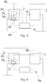
- Fig. 3 illustrates an engine system according to a further embodiment of the disclosure.
- the arrangement of Fig. 3 differs from that of Fig. 2 by having means for obtaining engine environment condition information 1a.
- such means comprise one or more conventional sensors of the internal combustion engine 1 coupled to the control device 3, as illustrated by the dashed line extending therebetween.
- the analysing unit 2 comprises means for adjusting analysing unit environment conditions 2d, also coupled to the control device 3, as illustrated by a dashed line therebetween.
- Such an arrangement enables that the air provided form the air intake line 4b to the rapid compression machine 2a, via the means for adjusting analysing unit environment conditions 2d, may be adjusted so as to correspond to the air that is delivered to a cylinder of the internal combustion engine, even if air from the air intake line 4b is processed by the internal combustion engine prior to being delivered to the cylinder for combustion.
- Fig. 4 illustrates an engine system according to yet another embodiment of the disclosure.
- the arrangement of Fig. 4 differs from that of Fig. 2 in that the rapid compression machine is arranged in fluid communication with an air intake line 4b of the internal combustion engine 1 at a point downstream of any possible processing by the internal combustion engine (such as a charger and/or charge cooler).
- This arrangement provides the analysing unit 2 with air, for combustion with the gaseous fuel to be analysed, in a state corresponding to that of air being introduced to a cylinder of said engine.
Landscapes
- Engineering & Computer Science (AREA)
- Chemical & Material Sciences (AREA)
- Combustion & Propulsion (AREA)
- Mechanical Engineering (AREA)
- General Engineering & Computer Science (AREA)
- Physics & Mathematics (AREA)
- General Physics & Mathematics (AREA)
- Output Control And Ontrol Of Special Type Engine (AREA)
- Electrical Control Of Air Or Fuel Supplied To Internal-Combustion Engine (AREA)
Description
- The present disclosure relates to the control of internal combustion engines, and more particularly to the control of reciprocating internal combustion piston engines capable of using gaseous fuel as main fuel. The present disclosure further concerns a control method for such engines based on fuel properties, and a respective engine system with fuel properties analysis
- Internal combustion engines capable of using gaseous fuel as main fuel may often be operated on different types of gaseous fuel, e.g. gases of various compositions. This is due to the fact, that the composition of natural gas varies depending on the deposit from which the gas is recovered from.
- Typically, it is the provider of the gaseous fuel that also provides information on the composition of said gas, and the operator of the engine calculates fuel properties based on the given information concerning composition. The calculated fuel properties are then used to adjust engine control parameters so that the engine is better optimized for the fuel composition, and to avoid certain problems, such as knocking.
- However, calculating fuel properties for a given composition always results in an estimate, which may vary to some extent from the actual properties of the gaseous fuel. Moreover, filling a gaseous fuel reservoir with various types of gaseous fuel results in a mixture of gaseous fuels, which in turn requires more complex calculations for evaluating the properties of the mixture.
-
DE 602 10 846 T2 describes a control method according to the preamble ofclaim 1. -
US 2005/229479 A1 describes a method for monitoring the octane number of a fuel using a rapid compression machine. - An object of the present disclosure is to provide a control method for an internal combustion engine and an engine system having an internal combustion engine, such as reciprocating internal combustion piston engine, so as to facilitate adaption between different fuel properties of gaseous fuels having different compositions.
- The objects of the disclosure are achieved by a control method and an engine system which are characterized by what is stated in the independent claims. The preferred embodiments of the disclosure are disclosed in the dependent claims.
- The disclosure is based on the idea of providing an analysing unit having a rapid compression machine in connection with an internal combustion engine capable of using gaseous fuel as main fuel, and using information provided by the analysing unit to control the engine.
- An advantage provided by the disclosure is that information regarding fuel properties of the gaseous fuel actually delivered to the internal combustion engine is readily available for use in controlling said engine.
- In the following, the disclosure will be described in greater detail by means of preferred embodiments with reference to the accompanying drawings, in which:
-
Figure 1 is a schematic illustration of an engine system according to an embodiment of the disclosure; -
Figure 2 is a schematic illustration of an engine system according to another embodiment of the disclosure, in which fuel and air are delivered via separate lines; -
Figure 3 is a schematic illustration of an engine system according to yet another embodiment of the disclosure, in which fuel and air are delivered via separate lines and analysing unit environment conditions are adjusted based on engine environment conditions; and -
Figure 4 is a schematic illustration of an engine system according to further embodiment of the disclosure, in which fuel and air are delivered via separate lines, such that air is provided to the analysing unit in a state corresponding to that of air being introduced to a cylinder of an engine. - It should be noted that, for the purpose of clarity, the appended drawings illustrate embodiments of the disclosure in a schematic and simplified manner, and should not thus be interpreted in a restricting manner.
- According to a first aspect of the present disclosure, a control method for an
internal combustion engine 1 is provided, said control method being based on fuel properties and said engine being capable of using gaseous fuel as main fuel. - In the method, an
analysing unit 2 for analysing fuel properties of gaseous fuel is provided. Particularly, the analysingunit 2 comprises arapid compression machine 2a arranged in fluid communication with afuel delivery line 4; 4a of theinternal combustion engine 1, so as to receive at least gaseous fuel to be analysed. Thefuel delivery line 4a may be configured as a gaseous fuel feed line, i.e. delivering only gaseous fuel, in which case air has to be provided separately both for the analysingunit 2 and theinternal combustion engine 1. Alternatively, thefuel delivery line 4 may be configured as an intake line, i.e. delivering a combination of gaseous fuel and air to be combusted together in both the analysingunit 2 and theinternal combustion engine 1. - The gaseous fuel to be analysed is compressed within a
compression chamber 2b of the analysing unit so as to induce said fuel to auto-ignite and combust with air. Moreover, pressure data indicative of fuel properties is obtained from this combustion. - Information indicative of the fuel properties is transmitted to the
control device 3, and engine control parameters are controlled at least based on the information indicative of fuel properties. The information indicative of fuel properties could be, for example, pressure data obtained from apressure sensor 2c, or information derived at least from the pressure data by theanalysing unit 2. Examples of such engine control parameters include, but are not limited to, ignition timing, pilot fuel injection timing, pilot fuel injection quantity, fuel/air -ratio, manifold air pressure, valve timing, maximum engine load, and engine speed. - Fuel auto ignition delay properties are determined from the obtained pressure data, and correspondingly, engine control parameters are controlled based at least on the determined fuel auto ignition delay properties. It should be noted, that the fuel auto ignition delay properties may be determined by the analysing
unit 2 and transmitted to thecontrol device 3, or alternatively, the fuel auto ignition delay properties may be determined by thecontrol device 3 based on the information transmitted from theanalysing unit 2. - According to an embodiment of the first aspect, engine environment condition information is obtained. In the context of this disclosure, the term engine environment condition(s) is used to describe the conditions in which the engine is operated and which affect the operation of the engine. Most suitably, means for obtaining engine
environment condition information 1a are provided as conventional sensors typically present in common internal combustion engine systems capable of using gaseous fuel as main fuel. Moreover, respective analysing unit environment conditions are adjusted so as to correspond, or at least more closely to correspond with the obtained engine environment condition information. It should be noted, that although the analysing unit environment conditions may be adjusted to match the engine environment conditions, the analysing unit environment may alternatively be adjusted to correspond to the engine environment condition information according to a pre-determined set of rules, such as a chart, table or map. This has an advantage in that less approximation is needed. One option is to select and adjust he engine environment condition towards a pre-determined environment, which is closest to the engine environment condition information. - Preferably, but not necessarily, said engine environment condition information is indicative of at least one of engine intake air temperature, engine intake air pressure and engine intake air humidity. Correspondingly adjusting analysing unit environment conditions comprises preferably, but not necessarily, adjusting at least one of analysing unit intake air temperature, analysing unit intake air pressure and analysing unit intake air humidity, respectively. For example, intake air temperature can be adjusted with heat exchanger.
- According to a further embodiment of the first aspect, the analysing
unit 2 is provided with air for combusting with gaseous fuel to be analysed, such that the is provided from anair intake line 4b of theinternal combustion engine 1 in a state corresponding to that of air being introduced to a cylinder of said engine. For example, air may be provided to theanalysing unit 2 from anair intake line 4b of theinternal combustion engine 1 downstream of any air processing equipment, such as a charging device, charge cooler, or both (not illustrated). In such an arrangement, the properties of the air provided to theanalysing unit 2 are effectively the same as those of the air provided for theinternal combustion engine 1. Correspondingly, environment conditions similar to those of theinternal combustion engine 1 are achieved for the analysingunit 2 with minimal or none analysing unit environment conditions adjustments. - According to still another embodiment of the first aspect, compressing the gaseous fuel to be analysed within the
compression chamber 2b of analysingunit 2 is actuated by mechanical power or fluid power derived from the engine or peripherals thereof. Alternatively, thecompression chamber 2b may be actuated by electrical power derived from a generator attached to the internal combustion engine, or from the grid. - According to a second aspect of the disclosure, an engine system with fuel properties analysis is provided.
- The engine system comprises an
internal combustion engine 1 capable of using gaseous fuel as main fuel, afuel delivery line 4; 4a for providing gaseous fuel to the engine, and acontrol device 3 for controlling engine control parameters of the engine. - The engine system is further equipped with an analysing
unit 2 for analysing fuel properties of gaseous fuel. Particularly, theanalysing unit 2 comprises arapid compression machine 2a in fluid communication with thefuel delivery line 4; 4a for receiving at least gaseous fuel to be analysed. Therapid compression machine 2a has acompression chamber 2b arranged to compress, for example with a piston (not shown), said fuel so as to induce said fuel to auto-ignite and combust with air. - The
fuel delivery line 4a may be configured as a gaseous fuel feed line, i.e. delivering only gaseous fuel, in which case air has to be provided separately both for the analysingunit 2 and theinternal combustion engine 1. Alternatively, thefuel delivery line 4 may be configured as an intake line, i.e. delivering a combination of gaseous fuel and air to be combusted together in both the analysingunit 2 and theinternal combustion engine 1. The analysingunit 2 is also equipped with apressure sensor 2c for obtaining pressure data of a combustion within the compression chamber of the rapid compression machine, said pressure data being indicative of fuel properties. Furthermore, the analysingunit 2 is arranged to transmit information indicative of fuel properties to thecontrol device 3. The information indicative of fuel properties could be, for example, pressure data obtained from thepressure sensors 2c, or information derived at least from the pressure data by theanalysing unit 2. - Moreover, the
control device 3 is being further arranged to control engine control parameters at least based on said information indicative of fuel properties. Examples of such engine control parameters include, but are not limited to, ignition timing, pilot fuel injection timing, pilot fuel injection quantity, fuel/air -ratio, manifold air pressure, valve timing, maximum engine load, and engine speed. - The control device is further arranged to control engine control parameters based on at least fuel auto ignition delay properties determined from pressure data obtained from the
pressure sensor 2c. It should be noted, that the fuel auto ignition delay properties may be determined by the analysingunit 2 and transmitted to thecontrol device 3, or alternatively, the fuel auto ignition delay properties may be determined by thecontrol device 3 based on the information transmitted from the analysingunit 2. - According to an embodiment of the second aspect, the engine system comprises means for obtaining engine
environment condition information 1a. Most suitably, means for obtaining engineenvironment condition information 1a are provided as conventional sensors typically present in common internal combustion engine systems capable of using gaseous fuel as main fuel. Correspondingly, the analysing unit comprises means for adjusting analysingunit environment conditions 2d. Moreover, the means for adjusting analysingunit environment conditions 2d are arranged to adjust analysing unit environment conditions corresponding to engine environment condition information. - Preferably, but not necessarily, said means for obtaining
engine environment condition 1a information are arranged to obtain engine environment condition information indicative of at least one of engine intake air temperature, engine intake air pressure and engine intake air humidity. Correspondingly said means for adjusting analysingunit environment conditions 2d are preferably, but not necessarily, arranged to adjust at least one of analysing unit intake air temperature, analysing unit intake air pressure and analysing unit intake air humidity, respectively. - According to a further embodiment of the second aspect, the
rapid compression machine 2a is arranged in fluid communication with anair intake line 4b of theinternal combustion engine 1 so as to provide air, in a state corresponding to that of air being introduced to a cylinder of said engine, for combustion with the gaseous fuel to be analysed. For example, air may be provided to the analysingunit 2 from anair intake line 4b of theinternal combustion engine 1 downstream of any air processing equipment, such as a charging device, charge cooler, or both (not illustrated). In such an arrangement, the properties of the air provided to the analysingunit 2 are effectively the same as those of the air provided for theinternal combustion engine 1. Correspondingly, environment conditions similar to those of the internal combustion engine are achieved for the analysing unit with minimal or none analysing unit environment conditions adjustments. - According to still another embodiment of the second aspect, the analysing
unit 2 is arranged in power transmission with the engine for actuating the analysingunit 2, i.e. in order to compress fuel in thecompression chamber 2b. Most suitably such power transmission is arranged for mechanical power or fluid power derived from the engine, or peripherals thereof. Alternatively, thecompression chamber 2b may be actuated by electrical power derived from a generator attached to the internal combustion engine, or from the grid or with air from separate pressurized air vessel/container. -
Fig. 1 illustrates schematically an engine system according to an embodiment of the disclosure. Aninternal combustion engine 1 capable of using gaseous fuel as main fuel is coupled in fluid communication with afuel delivery line 4 for providing at least gaseous fuel. The engine control parameters of theinternal combustion engine 1 are controlled by thecontrol device 3, the communication interface between theengine 1 and thecontrol device 3 being represented as dashed line therebetween. The analysingunit 2 having arapid compression machine 2a with acompression chamber 2b is also coupled in fluid communication with thefuel delivery line 4 for providing at least gaseous fuel to thecompression chamber 2b of therapid compression machine 2a. As the gaseous fuel to be analysed from thefuel delivery line 4 compressed with air in thecompression chamber 2b, it auto-ignites and combusts. Thepressure sensor 2c obtains compression data from this combustion and this data is transmitted to thecontrol device 3 via the communication interface represented as a dashed line therebetween. Moreover, as the pressure data is indicative of the fuel properties of the gaseous fuel analysed, this pressure data is utilized by thecontrol device 3 to control the engine control parameters of theengine 1 so as to adapt to the fuel properties of the gaseous fuel. - As discusses earlier, the
fuel delivery line 4 may deliver only gaseous fuel, or a combination of gaseous fuel and air to be combusted together in both the analysingunit 2 and theinternal combustion engine 1. -
Fig. 2 illustrates schematically an engine system according an alternative embodiment of the disclosure, differing from that ofFig. 1 by having thefuel delivery line 4a configured to deliver only gaseous fuel, while a separateair intake line 4b is delivering air for combustion for both the analysingunit 2 and theinternal combustion engine 1. It should be noted, that particularly the air received from theair intake line 4b by theinternal combustion engine 1 may be further treated by, e.g. a charger and/ or a charge cooler. -
Fig. 3 illustrates an engine system according to a further embodiment of the disclosure. The arrangement ofFig. 3 differs from that ofFig. 2 by having means for obtaining engineenvironment condition information 1a. Suitably, such means comprise one or more conventional sensors of theinternal combustion engine 1 coupled to thecontrol device 3, as illustrated by the dashed line extending therebetween. Moreover, the analysingunit 2 comprises means for adjusting analysingunit environment conditions 2d, also coupled to thecontrol device 3, as illustrated by a dashed line therebetween. Such an arrangement enables that the air provided form theair intake line 4b to therapid compression machine 2a, via the means for adjusting analysingunit environment conditions 2d, may be adjusted so as to correspond to the air that is delivered to a cylinder of the internal combustion engine, even if air from theair intake line 4b is processed by the internal combustion engine prior to being delivered to the cylinder for combustion. -
Fig. 4 illustrates an engine system according to yet another embodiment of the disclosure. Particularly, the arrangement ofFig. 4 differs from that ofFig. 2 in that the rapid compression machine is arranged in fluid communication with anair intake line 4b of theinternal combustion engine 1 at a point downstream of any possible processing by the internal combustion engine (such as a charger and/or charge cooler). This arrangement provides the analysingunit 2 with air, for combustion with the gaseous fuel to be analysed, in a state corresponding to that of air being introduced to a cylinder of said engine.
Claims (10)
- A control method for an internal combustion engine (1) based on fuel properties, said engine being capable of using gaseous fuel as main fuel, the method comprising the following steps:- providing an analysing unit (2) for analysing fuel properties of gaseous fuel, characterized in that the analysing unit (2) comprises a rapid compression machine (2a), arranged in fluid communication with a fuel delivery line (4; 4a) of the internal combustion engine (1) for receiving at least gaseous fuel to be analysed, wherein the method further comprises the following steps of:- compressing said fuel within a compression chamber (2b) of the analysing unit so as to induce said fuel to auto-ignite and combust with air;- obtaining pressure data of said combustion, said pressure data being indicative of fuel auto ignition delay properties;- determining fuel auto ignition delay properties at least from the obtained pressure data;- transmitting information indicative of fuel auto ignition delay properties to the control device, and- controlling engine control parameters at least based on the determined fuel auto ignition delay properties.
- The control method according to Claim 1, characterized by
obtaining engine environment condition information, and
adjusting analysing unit environment conditions corresponding to obtained engine environment condition information. - The control method of Claim 2, characterized in that
said engine environment condition information is indicative of at least one of engine intake air temperature, engine intake air pressure and engine intake air humidity, and wherein
adjusting analysing unit (2) environment conditions comprises adjusting at least one of analysing unit intake air temperature, analysing unit intake air pressure and analysing unit intake air humidity, respectively. - The control method according to any of the preceding Claims 1-3, characterized by providing the analysing unit (2) with air for combusting with gaseous fuel to be analysed, said air being provided from an air intake line (4b) of the internal combustion engine (1) in a state corresponding to that of air being introduced to a cylinder of said engine.
- The control method according to any of the preceding Claims 1-4, characterized in that compressing said fuel within the compression chamber (2b) of analysing unit (2) is actuated by mechanical power or fluid power derived from the engine (1) or peripherals thereof.
- An engine system with fuel properties analysis, comprising:- an internal combustion engine (1) capable of using gaseous fuel as main fuel;- a fuel delivery line (4; 4a) for providing gaseous fuel to the engine;- a control device (3) for controlling engine control parameters of the engine, and- an analysing unit (2) for analysing fuel properties of gaseous fuel,characterized in that the analysing unit comprises:- a rapid compression machine (2a) in fluid communication with the fuel delivery line (4; 4a) for receiving at least gaseous fuel to be analysed, the rapid compression machine having a compression chamber (2b) arranged to compress said fuel so as to induce said fuel to auto-ignite and combust with air, and- a pressure sensor (2c) for obtaining pressure data of a combustion within the compression chamber of the rapid compression machine, said pressure data being indicative of fuel auto ignition delay properties.
the analysing unit (2) being arranged to determine fuel auto ignition delay properties at least from the obtained pressure data and transmit information indicative of fuel auto ignition delay properties to the control device (3), and
the control device (3) being further arranged to control engine control parameters at least based on said information indicative of fuel auto ignition delay properties. - The engine system according to Claim 6, characterized in that
the system comprises means for obtaining engine environment condition information (1a), and
the analysing unit (2) comprises means for adjusting analysing unit environment conditions (2d), wherein
said means for adjusting analysing unit environment conditions (2d) being arranged to adjust analysing unit environment conditions corresponding to engine environment condition information. - The engine system according to Claim 7, characterized in that
said means for obtaining engine environment condition (1a) information are arranged to obtain engine environment condition information indicative of at least one of engine intake air temperature, engine intake air pressure and engine intake air humidity, and said means for adjusting analysing unit environment conditions (2d) are arranged to adjust at least one of analysing unit intake air temperature, analysing unit intake air pressure and analysing unit intake air humidity, respectively. - The engine system according to any of the preceding Claims 6-8, characterized in that the rapid compression machine (2a) is arranged in fluid communication with an air intake line (4b) of the internal combustion engine (1) so as to provide air, in a state corresponding to that of air being introduced to a cylinder of said engine, for combustion with the gaseous fuel to be analysed
- The engine system according to any of the preceding Claims 6-9, characterized in that the analysing unit (2) is in power transmission with the engine (1) so as to actuate the rapid compression machine (2a) by mechanical or fluid power derived from the engine or peripherals thereof in order to compress fuel in the compression chamber (2b).
Applications Claiming Priority (1)
| Application Number | Priority Date | Filing Date | Title |
|---|---|---|---|
| PCT/FI2017/050253 WO2018189412A1 (en) | 2017-04-10 | 2017-04-10 | A control method for an internal combustion engine based on fuel properties, and an engine system with fuel properties analysis |
Publications (2)
| Publication Number | Publication Date |
|---|---|
| EP3610146A1 EP3610146A1 (en) | 2020-02-19 |
| EP3610146B1 true EP3610146B1 (en) | 2020-11-25 |
Family
ID=58645096
Family Applications (1)
| Application Number | Title | Priority Date | Filing Date |
|---|---|---|---|
| EP17720534.1A Active EP3610146B1 (en) | 2017-04-10 | 2017-04-10 | A control method for an internal combustion engine based on fuel properties, and an engine system with fuel properties analysis |
Country Status (2)
| Country | Link |
|---|---|
| EP (1) | EP3610146B1 (en) |
| WO (1) | WO2018189412A1 (en) |
Families Citing this family (2)
| Publication number | Priority date | Publication date | Assignee | Title |
|---|---|---|---|---|
| CN109488470B (en) * | 2018-11-26 | 2022-04-05 | 潍柴动力股份有限公司 | Method and device for adjusting air-fuel ratio |
| CN113283080B (en) * | 2021-05-25 | 2022-10-25 | 西安交通大学 | Method for quickly compensating heat of combustion chamber of compressor |
Family Cites Families (4)
| Publication number | Priority date | Publication date | Assignee | Title |
|---|---|---|---|---|
| US6598584B2 (en) * | 2001-02-23 | 2003-07-29 | Clean Air Partners, Inc. | Gas-fueled, compression ignition engine with maximized pilot ignition intensity |
| US20050229479A1 (en) * | 2004-04-14 | 2005-10-20 | Fernandes Joseph B | Fuel compositions and methods thereof |
| JP4826560B2 (en) * | 2007-08-13 | 2011-11-30 | トヨタ自動車株式会社 | Fuel property detection device for internal combustion engine |
| US9441561B2 (en) * | 2014-12-11 | 2016-09-13 | Caterpillar Inc. | System and method for increasing tolerance to fuel variation |
-
2017
- 2017-04-10 WO PCT/FI2017/050253 patent/WO2018189412A1/en not_active Ceased
- 2017-04-10 EP EP17720534.1A patent/EP3610146B1/en active Active
Non-Patent Citations (1)
| Title |
|---|
| None * |
Also Published As
| Publication number | Publication date |
|---|---|
| WO2018189412A1 (en) | 2018-10-18 |
| EP3610146A1 (en) | 2020-02-19 |
Similar Documents
| Publication | Publication Date | Title |
|---|---|---|
| RU2423618C2 (en) | Sensor of actual fuel quality | |
| US5713340A (en) | System for fueling an internal combustion engine with low and high pressure gaseous fuel | |
| JPS63501088A (en) | Dual fuel compression ignition engine | |
| US20140366840A1 (en) | Fuel Apportionment for Multi Fuel Engine System | |
| US9441561B2 (en) | System and method for increasing tolerance to fuel variation | |
| US20150345408A1 (en) | Fuel apportionment for multi fuel engine system | |
| US20160169133A1 (en) | System and method for increasing gaseous fuel substitution | |
| US20140366839A1 (en) | Transient Event Fuel Apportionment for Multi Fuel Engine System | |
| EP2927467B1 (en) | Gas or dual fuel engine | |
| CN104863729A (en) | Method for operating internal combustion engine | |
| CN107816390A (en) | Automatic calibration system and method for dual fuel internal combustion engine | |
| EP3610146B1 (en) | A control method for an internal combustion engine based on fuel properties, and an engine system with fuel properties analysis | |
| CN107787399A (en) | bi-fuel internal combustion engine | |
| CN106194451A (en) | The method that multifuel engine and multifuel engine are run | |
| CN113309621B (en) | Engine with a motor | |
| JP7660003B2 (en) | Fuel injection system and relative control method for a spark ignition internal combustion engine | |
| EP3434885B1 (en) | Method of operating an electric power generator set and an electric power generator set | |
| US20200056566A1 (en) | Method and Device for Increasing the Global Compression Ratio of an Internal Combustion Engine in the Case of Varying Fuel Quality | |
| EP3179080B1 (en) | Method for operating an engine | |
| WO2018063973A4 (en) | System and methods for combustion control in multi-cylinder opposed piston engines | |
| AU2018201531B2 (en) | Engine and control strategy for injecting augmenting fuel to stream of gaseous fuel and air | |
| CN108204305B (en) | Hybrid combustion system and method | |
| DK181214B1 (en) | A large two-stroke uniflow scavenged gaseous fueled engine and method for controlling supply of liquid fuel | |
| KR20160041523A (en) | Cylinder balancing system and method using knock intensity of dual fuel engine | |
| KR101620051B1 (en) | Control device for natural gas supply of dual fuel generator engine |
Legal Events
| Date | Code | Title | Description |
|---|---|---|---|
| STAA | Information on the status of an ep patent application or granted ep patent |
Free format text: STATUS: UNKNOWN |
|
| STAA | Information on the status of an ep patent application or granted ep patent |
Free format text: STATUS: THE INTERNATIONAL PUBLICATION HAS BEEN MADE |
|
| PUAI | Public reference made under article 153(3) epc to a published international application that has entered the european phase |
Free format text: ORIGINAL CODE: 0009012 |
|
| STAA | Information on the status of an ep patent application or granted ep patent |
Free format text: STATUS: REQUEST FOR EXAMINATION WAS MADE |
|
| 17P | Request for examination filed |
Effective date: 20191025 |
|
| AK | Designated contracting states |
Kind code of ref document: A1 Designated state(s): AL AT BE BG CH CY CZ DE DK EE ES FI FR GB GR HR HU IE IS IT LI LT LU LV MC MK MT NL NO PL PT RO RS SE SI SK SM TR |
|
| GRAP | Despatch of communication of intention to grant a patent |
Free format text: ORIGINAL CODE: EPIDOSNIGR1 |
|
| STAA | Information on the status of an ep patent application or granted ep patent |
Free format text: STATUS: GRANT OF PATENT IS INTENDED |
|
| INTG | Intention to grant announced |
Effective date: 20200729 |
|
| GRAS | Grant fee paid |
Free format text: ORIGINAL CODE: EPIDOSNIGR3 |
|
| GRAA | (expected) grant |
Free format text: ORIGINAL CODE: 0009210 |
|
| STAA | Information on the status of an ep patent application or granted ep patent |
Free format text: STATUS: THE PATENT HAS BEEN GRANTED |
|
| AK | Designated contracting states |
Kind code of ref document: B1 Designated state(s): AL AT BE BG CH CY CZ DE DK EE ES FI FR GB GR HR HU IE IS IT LI LT LU LV MC MK MT NL NO PL PT RO RS SE SI SK SM TR |
|
| REG | Reference to a national code |
Ref country code: GB Ref legal event code: FG4D |
|
| REG | Reference to a national code |
Ref country code: CH Ref legal event code: EP |
|
| REG | Reference to a national code |
Ref country code: AT Ref legal event code: REF Ref document number: 1338583 Country of ref document: AT Kind code of ref document: T Effective date: 20201215 |
|
| REG | Reference to a national code |
Ref country code: DE Ref legal event code: R096 Ref document number: 602017028240 Country of ref document: DE |
|
| REG | Reference to a national code |
Ref country code: IE Ref legal event code: FG4D |
|
| REG | Reference to a national code |
Ref country code: AT Ref legal event code: MK05 Ref document number: 1338583 Country of ref document: AT Kind code of ref document: T Effective date: 20201125 |
|
| REG | Reference to a national code |
Ref country code: NL Ref legal event code: MP Effective date: 20201125 |
|
| PG25 | Lapsed in a contracting state [announced via postgrant information from national office to epo] |
Ref country code: GR Free format text: LAPSE BECAUSE OF FAILURE TO SUBMIT A TRANSLATION OF THE DESCRIPTION OR TO PAY THE FEE WITHIN THE PRESCRIBED TIME-LIMIT Effective date: 20210226 Ref country code: FI Free format text: LAPSE BECAUSE OF FAILURE TO SUBMIT A TRANSLATION OF THE DESCRIPTION OR TO PAY THE FEE WITHIN THE PRESCRIBED TIME-LIMIT Effective date: 20201125 Ref country code: NO Free format text: LAPSE BECAUSE OF FAILURE TO SUBMIT A TRANSLATION OF THE DESCRIPTION OR TO PAY THE FEE WITHIN THE PRESCRIBED TIME-LIMIT Effective date: 20210225 Ref country code: RS Free format text: LAPSE BECAUSE OF FAILURE TO SUBMIT A TRANSLATION OF THE DESCRIPTION OR TO PAY THE FEE WITHIN THE PRESCRIBED TIME-LIMIT Effective date: 20201125 Ref country code: PT Free format text: LAPSE BECAUSE OF FAILURE TO SUBMIT A TRANSLATION OF THE DESCRIPTION OR TO PAY THE FEE WITHIN THE PRESCRIBED TIME-LIMIT Effective date: 20210325 |
|
| PG25 | Lapsed in a contracting state [announced via postgrant information from national office to epo] |
Ref country code: SE Free format text: LAPSE BECAUSE OF FAILURE TO SUBMIT A TRANSLATION OF THE DESCRIPTION OR TO PAY THE FEE WITHIN THE PRESCRIBED TIME-LIMIT Effective date: 20201125 Ref country code: LV Free format text: LAPSE BECAUSE OF FAILURE TO SUBMIT A TRANSLATION OF THE DESCRIPTION OR TO PAY THE FEE WITHIN THE PRESCRIBED TIME-LIMIT Effective date: 20201125 Ref country code: IS Free format text: LAPSE BECAUSE OF FAILURE TO SUBMIT A TRANSLATION OF THE DESCRIPTION OR TO PAY THE FEE WITHIN THE PRESCRIBED TIME-LIMIT Effective date: 20210325 Ref country code: PL Free format text: LAPSE BECAUSE OF FAILURE TO SUBMIT A TRANSLATION OF THE DESCRIPTION OR TO PAY THE FEE WITHIN THE PRESCRIBED TIME-LIMIT Effective date: 20201125 Ref country code: BG Free format text: LAPSE BECAUSE OF FAILURE TO SUBMIT A TRANSLATION OF THE DESCRIPTION OR TO PAY THE FEE WITHIN THE PRESCRIBED TIME-LIMIT Effective date: 20210225 Ref country code: AT Free format text: LAPSE BECAUSE OF FAILURE TO SUBMIT A TRANSLATION OF THE DESCRIPTION OR TO PAY THE FEE WITHIN THE PRESCRIBED TIME-LIMIT Effective date: 20201125 |
|
| REG | Reference to a national code |
Ref country code: LT Ref legal event code: MG9D |
|
| PG25 | Lapsed in a contracting state [announced via postgrant information from national office to epo] |
Ref country code: HR Free format text: LAPSE BECAUSE OF FAILURE TO SUBMIT A TRANSLATION OF THE DESCRIPTION OR TO PAY THE FEE WITHIN THE PRESCRIBED TIME-LIMIT Effective date: 20201125 |
|
| PG25 | Lapsed in a contracting state [announced via postgrant information from national office to epo] |
Ref country code: SK Free format text: LAPSE BECAUSE OF FAILURE TO SUBMIT A TRANSLATION OF THE DESCRIPTION OR TO PAY THE FEE WITHIN THE PRESCRIBED TIME-LIMIT Effective date: 20201125 Ref country code: RO Free format text: LAPSE BECAUSE OF FAILURE TO SUBMIT A TRANSLATION OF THE DESCRIPTION OR TO PAY THE FEE WITHIN THE PRESCRIBED TIME-LIMIT Effective date: 20201125 Ref country code: SM Free format text: LAPSE BECAUSE OF FAILURE TO SUBMIT A TRANSLATION OF THE DESCRIPTION OR TO PAY THE FEE WITHIN THE PRESCRIBED TIME-LIMIT Effective date: 20201125 Ref country code: EE Free format text: LAPSE BECAUSE OF FAILURE TO SUBMIT A TRANSLATION OF THE DESCRIPTION OR TO PAY THE FEE WITHIN THE PRESCRIBED TIME-LIMIT Effective date: 20201125 Ref country code: CZ Free format text: LAPSE BECAUSE OF FAILURE TO SUBMIT A TRANSLATION OF THE DESCRIPTION OR TO PAY THE FEE WITHIN THE PRESCRIBED TIME-LIMIT Effective date: 20201125 Ref country code: LT Free format text: LAPSE BECAUSE OF FAILURE TO SUBMIT A TRANSLATION OF THE DESCRIPTION OR TO PAY THE FEE WITHIN THE PRESCRIBED TIME-LIMIT Effective date: 20201125 |
|
| REG | Reference to a national code |
Ref country code: DE Ref legal event code: R097 Ref document number: 602017028240 Country of ref document: DE |
|
| PG25 | Lapsed in a contracting state [announced via postgrant information from national office to epo] |
Ref country code: DK Free format text: LAPSE BECAUSE OF FAILURE TO SUBMIT A TRANSLATION OF THE DESCRIPTION OR TO PAY THE FEE WITHIN THE PRESCRIBED TIME-LIMIT Effective date: 20201125 |
|
| PLBE | No opposition filed within time limit |
Free format text: ORIGINAL CODE: 0009261 |
|
| STAA | Information on the status of an ep patent application or granted ep patent |
Free format text: STATUS: NO OPPOSITION FILED WITHIN TIME LIMIT |
|
| PG25 | Lapsed in a contracting state [announced via postgrant information from national office to epo] |
Ref country code: NL Free format text: LAPSE BECAUSE OF FAILURE TO SUBMIT A TRANSLATION OF THE DESCRIPTION OR TO PAY THE FEE WITHIN THE PRESCRIBED TIME-LIMIT Effective date: 20201125 Ref country code: AL Free format text: LAPSE BECAUSE OF FAILURE TO SUBMIT A TRANSLATION OF THE DESCRIPTION OR TO PAY THE FEE WITHIN THE PRESCRIBED TIME-LIMIT Effective date: 20201125 Ref country code: IT Free format text: LAPSE BECAUSE OF FAILURE TO SUBMIT A TRANSLATION OF THE DESCRIPTION OR TO PAY THE FEE WITHIN THE PRESCRIBED TIME-LIMIT Effective date: 20201125 |
|
| 26N | No opposition filed |
Effective date: 20210826 |
|
| PG25 | Lapsed in a contracting state [announced via postgrant information from national office to epo] |
Ref country code: SI Free format text: LAPSE BECAUSE OF FAILURE TO SUBMIT A TRANSLATION OF THE DESCRIPTION OR TO PAY THE FEE WITHIN THE PRESCRIBED TIME-LIMIT Effective date: 20201125 Ref country code: MC Free format text: LAPSE BECAUSE OF FAILURE TO SUBMIT A TRANSLATION OF THE DESCRIPTION OR TO PAY THE FEE WITHIN THE PRESCRIBED TIME-LIMIT Effective date: 20201125 |
|
| GBPC | Gb: european patent ceased through non-payment of renewal fee |
Effective date: 20210410 |
|
| PG25 | Lapsed in a contracting state [announced via postgrant information from national office to epo] |
Ref country code: LU Free format text: LAPSE BECAUSE OF NON-PAYMENT OF DUE FEES Effective date: 20210410 |
|
| REG | Reference to a national code |
Ref country code: BE Ref legal event code: MM Effective date: 20210430 |
|
| PG25 | Lapsed in a contracting state [announced via postgrant information from national office to epo] |
Ref country code: GB Free format text: LAPSE BECAUSE OF NON-PAYMENT OF DUE FEES Effective date: 20210410 Ref country code: FR Free format text: LAPSE BECAUSE OF NON-PAYMENT OF DUE FEES Effective date: 20210430 Ref country code: CH Free format text: LAPSE BECAUSE OF NON-PAYMENT OF DUE FEES Effective date: 20210430 Ref country code: LI Free format text: LAPSE BECAUSE OF NON-PAYMENT OF DUE FEES Effective date: 20210430 Ref country code: ES Free format text: LAPSE BECAUSE OF FAILURE TO SUBMIT A TRANSLATION OF THE DESCRIPTION OR TO PAY THE FEE WITHIN THE PRESCRIBED TIME-LIMIT Effective date: 20201125 |
|
| PG25 | Lapsed in a contracting state [announced via postgrant information from national office to epo] |
Ref country code: IE Free format text: LAPSE BECAUSE OF NON-PAYMENT OF DUE FEES Effective date: 20210410 |
|
| PG25 | Lapsed in a contracting state [announced via postgrant information from national office to epo] |
Ref country code: IS Free format text: LAPSE BECAUSE OF FAILURE TO SUBMIT A TRANSLATION OF THE DESCRIPTION OR TO PAY THE FEE WITHIN THE PRESCRIBED TIME-LIMIT Effective date: 20210325 |
|
| PG25 | Lapsed in a contracting state [announced via postgrant information from national office to epo] |
Ref country code: BE Free format text: LAPSE BECAUSE OF NON-PAYMENT OF DUE FEES Effective date: 20210430 |
|
| PG25 | Lapsed in a contracting state [announced via postgrant information from national office to epo] |
Ref country code: CY Free format text: LAPSE BECAUSE OF FAILURE TO SUBMIT A TRANSLATION OF THE DESCRIPTION OR TO PAY THE FEE WITHIN THE PRESCRIBED TIME-LIMIT Effective date: 20201125 |
|
| PG25 | Lapsed in a contracting state [announced via postgrant information from national office to epo] |
Ref country code: HU Free format text: LAPSE BECAUSE OF FAILURE TO SUBMIT A TRANSLATION OF THE DESCRIPTION OR TO PAY THE FEE WITHIN THE PRESCRIBED TIME-LIMIT; INVALID AB INITIO Effective date: 20170410 |
|
| PG25 | Lapsed in a contracting state [announced via postgrant information from national office to epo] |
Ref country code: MK Free format text: LAPSE BECAUSE OF FAILURE TO SUBMIT A TRANSLATION OF THE DESCRIPTION OR TO PAY THE FEE WITHIN THE PRESCRIBED TIME-LIMIT Effective date: 20201125 |
|
| PG25 | Lapsed in a contracting state [announced via postgrant information from national office to epo] |
Ref country code: TR Free format text: LAPSE BECAUSE OF FAILURE TO SUBMIT A TRANSLATION OF THE DESCRIPTION OR TO PAY THE FEE WITHIN THE PRESCRIBED TIME-LIMIT Effective date: 20201125 |
|
| PG25 | Lapsed in a contracting state [announced via postgrant information from national office to epo] |
Ref country code: MT Free format text: LAPSE BECAUSE OF FAILURE TO SUBMIT A TRANSLATION OF THE DESCRIPTION OR TO PAY THE FEE WITHIN THE PRESCRIBED TIME-LIMIT Effective date: 20201125 |
|
| PGFP | Annual fee paid to national office [announced via postgrant information from national office to epo] |
Ref country code: DE Payment date: 20250422 Year of fee payment: 9 |