EP3610138B1 - Waste heat recovery systems with heat exchangers - Google Patents
Waste heat recovery systems with heat exchangers Download PDFInfo
- Publication number
- EP3610138B1 EP3610138B1 EP18802581.1A EP18802581A EP3610138B1 EP 3610138 B1 EP3610138 B1 EP 3610138B1 EP 18802581 A EP18802581 A EP 18802581A EP 3610138 B1 EP3610138 B1 EP 3610138B1
- Authority
- EP
- European Patent Office
- Prior art keywords
- working fluid
- waste heat
- conversion device
- fluidically coupled
- recovery system
- Prior art date
- Legal status (The legal status is an assumption and is not a legal conclusion. Google has not performed a legal analysis and makes no representation as to the accuracy of the status listed.)
- Active
Links
Images

Classifications
-
- F—MECHANICAL ENGINEERING; LIGHTING; HEATING; WEAPONS; BLASTING
- F01—MACHINES OR ENGINES IN GENERAL; ENGINE PLANTS IN GENERAL; STEAM ENGINES
- F01K—STEAM ENGINE PLANTS; STEAM ACCUMULATORS; ENGINE PLANTS NOT OTHERWISE PROVIDED FOR; ENGINES USING SPECIAL WORKING FLUIDS OR CYCLES
- F01K23/00—Plants characterised by more than one engine delivering power external to the plant, the engines being driven by different fluids
- F01K23/02—Plants characterised by more than one engine delivering power external to the plant, the engines being driven by different fluids the engine cycles being thermally coupled
- F01K23/06—Plants characterised by more than one engine delivering power external to the plant, the engines being driven by different fluids the engine cycles being thermally coupled combustion heat from one cycle heating the fluid in another cycle
- F01K23/10—Plants characterised by more than one engine delivering power external to the plant, the engines being driven by different fluids the engine cycles being thermally coupled combustion heat from one cycle heating the fluid in another cycle with exhaust fluid of one cycle heating the fluid in another cycle
-
- F—MECHANICAL ENGINEERING; LIGHTING; HEATING; WEAPONS; BLASTING
- F01—MACHINES OR ENGINES IN GENERAL; ENGINE PLANTS IN GENERAL; STEAM ENGINES
- F01K—STEAM ENGINE PLANTS; STEAM ACCUMULATORS; ENGINE PLANTS NOT OTHERWISE PROVIDED FOR; ENGINES USING SPECIAL WORKING FLUIDS OR CYCLES
- F01K23/00—Plants characterised by more than one engine delivering power external to the plant, the engines being driven by different fluids
- F01K23/02—Plants characterised by more than one engine delivering power external to the plant, the engines being driven by different fluids the engine cycles being thermally coupled
- F01K23/06—Plants characterised by more than one engine delivering power external to the plant, the engines being driven by different fluids the engine cycles being thermally coupled combustion heat from one cycle heating the fluid in another cycle
- F01K23/065—Plants characterised by more than one engine delivering power external to the plant, the engines being driven by different fluids the engine cycles being thermally coupled combustion heat from one cycle heating the fluid in another cycle the combustion taking place in an internal combustion piston engine, e.g. a diesel engine
-
- F—MECHANICAL ENGINEERING; LIGHTING; HEATING; WEAPONS; BLASTING
- F01—MACHINES OR ENGINES IN GENERAL; ENGINE PLANTS IN GENERAL; STEAM ENGINES
- F01K—STEAM ENGINE PLANTS; STEAM ACCUMULATORS; ENGINE PLANTS NOT OTHERWISE PROVIDED FOR; ENGINES USING SPECIAL WORKING FLUIDS OR CYCLES
- F01K7/00—Steam engine plants characterised by the use of specific types of engine; Plants or engines characterised by their use of special steam systems, cycles or processes; Control means specially adapted for such systems, cycles or processes; Use of withdrawn or exhaust steam for feed-water heating
- F01K7/34—Steam engine plants characterised by the use of specific types of engine; Plants or engines characterised by their use of special steam systems, cycles or processes; Control means specially adapted for such systems, cycles or processes; Use of withdrawn or exhaust steam for feed-water heating the engines being of extraction or non-condensing type; Use of steam for feed-water heating
- F01K7/42—Use of desuperheaters for feed-water heating
-
- F—MECHANICAL ENGINEERING; LIGHTING; HEATING; WEAPONS; BLASTING
- F01—MACHINES OR ENGINES IN GENERAL; ENGINE PLANTS IN GENERAL; STEAM ENGINES
- F01M—LUBRICATING OF MACHINES OR ENGINES IN GENERAL; LUBRICATING INTERNAL COMBUSTION ENGINES; CRANKCASE VENTILATING
- F01M1/00—Pressure lubrication
- F01M1/02—Pressure lubrication using lubricating pumps
-
- F—MECHANICAL ENGINEERING; LIGHTING; HEATING; WEAPONS; BLASTING
- F01—MACHINES OR ENGINES IN GENERAL; ENGINE PLANTS IN GENERAL; STEAM ENGINES
- F01M—LUBRICATING OF MACHINES OR ENGINES IN GENERAL; LUBRICATING INTERNAL COMBUSTION ENGINES; CRANKCASE VENTILATING
- F01M5/00—Heating, cooling, or controlling temperature of lubricant; Lubrication means facilitating engine starting
- F01M5/002—Cooling
-
- F—MECHANICAL ENGINEERING; LIGHTING; HEATING; WEAPONS; BLASTING
- F01—MACHINES OR ENGINES IN GENERAL; ENGINE PLANTS IN GENERAL; STEAM ENGINES
- F01N—GAS-FLOW SILENCERS OR EXHAUST APPARATUS FOR MACHINES OR ENGINES IN GENERAL; GAS-FLOW SILENCERS OR EXHAUST APPARATUS FOR INTERNAL-COMBUSTION ENGINES
- F01N5/00—Exhaust or silencing apparatus combined or associated with devices profiting by exhaust energy
- F01N5/02—Exhaust or silencing apparatus combined or associated with devices profiting by exhaust energy the devices using heat
-
- F—MECHANICAL ENGINEERING; LIGHTING; HEATING; WEAPONS; BLASTING
- F01—MACHINES OR ENGINES IN GENERAL; ENGINE PLANTS IN GENERAL; STEAM ENGINES
- F01N—GAS-FLOW SILENCERS OR EXHAUST APPARATUS FOR MACHINES OR ENGINES IN GENERAL; GAS-FLOW SILENCERS OR EXHAUST APPARATUS FOR INTERNAL-COMBUSTION ENGINES
- F01N5/00—Exhaust or silencing apparatus combined or associated with devices profiting by exhaust energy
- F01N5/02—Exhaust or silencing apparatus combined or associated with devices profiting by exhaust energy the devices using heat
- F01N5/025—Exhaust or silencing apparatus combined or associated with devices profiting by exhaust energy the devices using heat the device being thermoelectric generators
-
- F—MECHANICAL ENGINEERING; LIGHTING; HEATING; WEAPONS; BLASTING
- F01—MACHINES OR ENGINES IN GENERAL; ENGINE PLANTS IN GENERAL; STEAM ENGINES
- F01N—GAS-FLOW SILENCERS OR EXHAUST APPARATUS FOR MACHINES OR ENGINES IN GENERAL; GAS-FLOW SILENCERS OR EXHAUST APPARATUS FOR INTERNAL-COMBUSTION ENGINES
- F01N5/00—Exhaust or silencing apparatus combined or associated with devices profiting by exhaust energy
- F01N5/04—Exhaust or silencing apparatus combined or associated with devices profiting by exhaust energy the devices using kinetic energy
-
- F—MECHANICAL ENGINEERING; LIGHTING; HEATING; WEAPONS; BLASTING
- F01—MACHINES OR ENGINES IN GENERAL; ENGINE PLANTS IN GENERAL; STEAM ENGINES
- F01P—COOLING OF MACHINES OR ENGINES IN GENERAL; COOLING OF INTERNAL-COMBUSTION ENGINES
- F01P11/00—Component parts, details, or accessories not provided for in, or of interest apart from, groups F01P1/00 - F01P9/00
-
- F—MECHANICAL ENGINEERING; LIGHTING; HEATING; WEAPONS; BLASTING
- F01—MACHINES OR ENGINES IN GENERAL; ENGINE PLANTS IN GENERAL; STEAM ENGINES
- F01P—COOLING OF MACHINES OR ENGINES IN GENERAL; COOLING OF INTERNAL-COMBUSTION ENGINES
- F01P3/00—Liquid cooling
- F01P3/18—Arrangements or mounting of liquid-to-air heat-exchangers
-
- F—MECHANICAL ENGINEERING; LIGHTING; HEATING; WEAPONS; BLASTING
- F01—MACHINES OR ENGINES IN GENERAL; ENGINE PLANTS IN GENERAL; STEAM ENGINES
- F01P—COOLING OF MACHINES OR ENGINES IN GENERAL; COOLING OF INTERNAL-COMBUSTION ENGINES
- F01P5/00—Pumping cooling-air or liquid coolants
- F01P5/10—Pumping liquid coolant; Arrangements of coolant pumps
-
- F—MECHANICAL ENGINEERING; LIGHTING; HEATING; WEAPONS; BLASTING
- F02—COMBUSTION ENGINES; HOT-GAS OR COMBUSTION-PRODUCT ENGINE PLANTS
- F02G—HOT GAS OR COMBUSTION-PRODUCT POSITIVE-DISPLACEMENT ENGINE PLANTS; USE OF WASTE HEAT OF COMBUSTION ENGINES; NOT OTHERWISE PROVIDED FOR
- F02G5/00—Profiting from waste heat of combustion engines, not otherwise provided for
-
- F—MECHANICAL ENGINEERING; LIGHTING; HEATING; WEAPONS; BLASTING
- F02—COMBUSTION ENGINES; HOT-GAS OR COMBUSTION-PRODUCT ENGINE PLANTS
- F02G—HOT GAS OR COMBUSTION-PRODUCT POSITIVE-DISPLACEMENT ENGINE PLANTS; USE OF WASTE HEAT OF COMBUSTION ENGINES; NOT OTHERWISE PROVIDED FOR
- F02G5/00—Profiting from waste heat of combustion engines, not otherwise provided for
- F02G5/02—Profiting from waste heat of exhaust gases
-
- F—MECHANICAL ENGINEERING; LIGHTING; HEATING; WEAPONS; BLASTING
- F02—COMBUSTION ENGINES; HOT-GAS OR COMBUSTION-PRODUCT ENGINE PLANTS
- F02G—HOT GAS OR COMBUSTION-PRODUCT POSITIVE-DISPLACEMENT ENGINE PLANTS; USE OF WASTE HEAT OF COMBUSTION ENGINES; NOT OTHERWISE PROVIDED FOR
- F02G5/00—Profiting from waste heat of combustion engines, not otherwise provided for
- F02G5/02—Profiting from waste heat of exhaust gases
- F02G5/04—Profiting from waste heat of exhaust gases in combination with other waste heat from combustion engines
-
- F—MECHANICAL ENGINEERING; LIGHTING; HEATING; WEAPONS; BLASTING
- F02—COMBUSTION ENGINES; HOT-GAS OR COMBUSTION-PRODUCT ENGINE PLANTS
- F02M—SUPPLYING COMBUSTION ENGINES IN GENERAL WITH COMBUSTIBLE MIXTURES OR CONSTITUENTS THEREOF
- F02M26/00—Engine-pertinent apparatus for adding exhaust gases to combustion-air, main fuel or fuel-air mixture, e.g. by exhaust gas recirculation [EGR] systems
- F02M26/13—Arrangement or layout of EGR passages, e.g. in relation to specific engine parts or for incorporation of accessories
- F02M26/22—Arrangement or layout of EGR passages, e.g. in relation to specific engine parts or for incorporation of accessories with coolers in the recirculation passage
-
- F—MECHANICAL ENGINEERING; LIGHTING; HEATING; WEAPONS; BLASTING
- F02—COMBUSTION ENGINES; HOT-GAS OR COMBUSTION-PRODUCT ENGINE PLANTS
- F02M—SUPPLYING COMBUSTION ENGINES IN GENERAL WITH COMBUSTIBLE MIXTURES OR CONSTITUENTS THEREOF
- F02M26/00—Engine-pertinent apparatus for adding exhaust gases to combustion-air, main fuel or fuel-air mixture, e.g. by exhaust gas recirculation [EGR] systems
- F02M26/13—Arrangement or layout of EGR passages, e.g. in relation to specific engine parts or for incorporation of accessories
- F02M26/22—Arrangement or layout of EGR passages, e.g. in relation to specific engine parts or for incorporation of accessories with coolers in the recirculation passage
- F02M26/23—Layout, e.g. schematics
-
- F—MECHANICAL ENGINEERING; LIGHTING; HEATING; WEAPONS; BLASTING
- F02—COMBUSTION ENGINES; HOT-GAS OR COMBUSTION-PRODUCT ENGINE PLANTS
- F02M—SUPPLYING COMBUSTION ENGINES IN GENERAL WITH COMBUSTIBLE MIXTURES OR CONSTITUENTS THEREOF
- F02M26/00—Engine-pertinent apparatus for adding exhaust gases to combustion-air, main fuel or fuel-air mixture, e.g. by exhaust gas recirculation [EGR] systems
- F02M26/13—Arrangement or layout of EGR passages, e.g. in relation to specific engine parts or for incorporation of accessories
- F02M26/22—Arrangement or layout of EGR passages, e.g. in relation to specific engine parts or for incorporation of accessories with coolers in the recirculation passage
- F02M26/29—Constructional details of the coolers, e.g. pipes, plates, ribs, insulation or materials
- F02M26/30—Connections of coolers to other devices, e.g. to valves, heaters, compressors or filters; Coolers characterised by their location on the engine
-
- F—MECHANICAL ENGINEERING; LIGHTING; HEATING; WEAPONS; BLASTING
- F02—COMBUSTION ENGINES; HOT-GAS OR COMBUSTION-PRODUCT ENGINE PLANTS
- F02M—SUPPLYING COMBUSTION ENGINES IN GENERAL WITH COMBUSTIBLE MIXTURES OR CONSTITUENTS THEREOF
- F02M26/00—Engine-pertinent apparatus for adding exhaust gases to combustion-air, main fuel or fuel-air mixture, e.g. by exhaust gas recirculation [EGR] systems
- F02M26/13—Arrangement or layout of EGR passages, e.g. in relation to specific engine parts or for incorporation of accessories
- F02M26/22—Arrangement or layout of EGR passages, e.g. in relation to specific engine parts or for incorporation of accessories with coolers in the recirculation passage
- F02M26/29—Constructional details of the coolers, e.g. pipes, plates, ribs, insulation or materials
- F02M26/32—Liquid-cooled heat exchangers
-
- F—MECHANICAL ENGINEERING; LIGHTING; HEATING; WEAPONS; BLASTING
- F01—MACHINES OR ENGINES IN GENERAL; ENGINE PLANTS IN GENERAL; STEAM ENGINES
- F01N—GAS-FLOW SILENCERS OR EXHAUST APPARATUS FOR MACHINES OR ENGINES IN GENERAL; GAS-FLOW SILENCERS OR EXHAUST APPARATUS FOR INTERNAL-COMBUSTION ENGINES
- F01N2240/00—Combination or association of two or more different exhaust treating devices, or of at least one such device with an auxiliary device, not covered by indexing codes F01N2230/00 or F01N2250/00, one of the devices being
- F01N2240/02—Combination or association of two or more different exhaust treating devices, or of at least one such device with an auxiliary device, not covered by indexing codes F01N2230/00 or F01N2250/00, one of the devices being a heat exchanger
-
- F—MECHANICAL ENGINEERING; LIGHTING; HEATING; WEAPONS; BLASTING
- F22—STEAM GENERATION
- F22D—PREHEATING, OR ACCUMULATING PREHEATED, FEED-WATER FOR STEAM GENERATION; FEED-WATER SUPPLY FOR STEAM GENERATION; CONTROLLING WATER LEVEL FOR STEAM GENERATION; AUXILIARY DEVICES FOR PROMOTING WATER CIRCULATION WITHIN STEAM BOILERS
- F22D1/00—Feed-water heaters, i.e. economisers or like preheaters
- F22D1/32—Feed-water heaters, i.e. economisers or like preheaters arranged to be heated by steam, e.g. bled from turbines
-
- Y—GENERAL TAGGING OF NEW TECHNOLOGICAL DEVELOPMENTS; GENERAL TAGGING OF CROSS-SECTIONAL TECHNOLOGIES SPANNING OVER SEVERAL SECTIONS OF THE IPC; TECHNICAL SUBJECTS COVERED BY FORMER USPC CROSS-REFERENCE ART COLLECTIONS [XRACs] AND DIGESTS
- Y02—TECHNOLOGIES OR APPLICATIONS FOR MITIGATION OR ADAPTATION AGAINST CLIMATE CHANGE
- Y02T—CLIMATE CHANGE MITIGATION TECHNOLOGIES RELATED TO TRANSPORTATION
- Y02T10/00—Road transport of goods or passengers
- Y02T10/10—Internal combustion engine [ICE] based vehicles
- Y02T10/12—Improving ICE efficiencies
Definitions
- the present disclosure generally relates to energy recovery systems, and more specifically to waste heat recovery systems with heat exchangers for internal combustion engines.
- Internal combustion engines are available in a variety of different configurations. Some are spark-ignited wherein a mixture of air and fuel (e.g., gasoline) is delivered to each of the engine's cylinders and ignited by, for example, a spark plug at a specific time during the engine cycle to cause combustion. The combustion moves a piston in the cylinder, causing rotation of a crankshaft, which delivers power to a drivetrain. Other engines are compression-ignited wherein a mixture of air and fuel (e.g., diesel) is delivered to each of cylinder which combusts as a result of compression of the mixture in the cylinder during the compression stroke of the piston. During operation, the engines often generate more heat and energy than needed for operation of the piston, the crankshaft, and the drivetrain.
- a mixture of air and fuel e.g., gasoline
- waste heat recovery systems to recover heat generated by the engines that would otherwise be lost through cooling and heat rejection provide means to improve engine efficiency.
- Heat is generally recovered from sources of high temperature, for example, the exhaust gas produced by the internal combustion engine (ICE), or compressed intake gas.
- ICE internal combustion engine
- high grade waste heat recovery systems include components which are configured to extract the heat from the high temperature source. These components can include exhaust gas recirculation (EGR) boilers, pre-charge air coolers (pre-CAC), exhaust system heat exchangers, or other components configured to extract heat from the high grade source of heat.
- EGR exhaust gas recirculation
- pre-CAC pre-charge air coolers
- exhaust system heat exchangers or other components configured to extract heat from the high grade source of heat.
- the invention is defined by the features of claim 1 and provides a waste heat recovery system.
- At least one heat exchanger is fluidically coupled to a waste heat source and is configured for selectively recovering heat from the waste heat source to heat a working fluid.
- At least one energy conversion device is fluidically coupled to the at least one heat exchanger and is configured to receive the working fluid and to generate an energy for performing work or transferring the energy to another device using the heat recovered from the waste heat source.
- a condenser is fluidically coupled to the at least one energy conversion device and is configured to receive the working fluid from the at least one energy conversion device and to condense the working fluid into a liquid phase.
- a recuperator is fluidically coupled to the at least one energy conversion device and is configured to receive the working fluid from the at least one energy conversion device and to communicate at least a portion of the working fluid to the at least one heat exchanger.
- the at least one energy conversion device provides an electric or mechanical power using the generated energy.
- the energy conversion device can be one of: a piston expander, a screw expander, a scroll expander, a gerotor expander, and a turbine expander.
- the energy conversion device includes at least one of: a plurality of working fluid inlets and a plurality of working fluid outlets.
- the working fluid includes at least one of: water, ethanol, toluene, ethylene glycol, water and ethylene glycol mixture, oil, R245fa, low GWP replacements for R245fa, R1233zd(e), other hydrocarbon based working fluid, other hydrofluorocarbon based working fluids, oil, any mixtures of these working fluids.
- the at least one heat exchanger or the recuperator includes at least one of: a plurality of microtubes and a plurality of microchannels.
- the waste heat source includes at least one of: an exhaust, a recirculated exhaust (EGR), a coolant, a lubricant, a charge air, and any combination of the aforementioned sources (e.g., a mixed-charge, which is EGR and charge air mixed together).
- EGR recirculated exhaust
- an exhaust boiler is fluidically coupled to the at least one heat exchanger and is configured to receive the working fluid from the at least one heat exchanger and to evaporate the working fluid and communicate the evaporated working fluid to the at least one energy conversion device.
- the exhaust boiler is configured to extract the heat from an exhaust generated from an after-treatment device to heat the working fluid.
- the recuperator includes a plurality of microtubes.
- the recuperator is fluidically coupled to the condenser, the at least one energy conversion device, and the at least one heat exchanger.
- the condenser is fluidically coupled to a sub-cooler which is fluidically coupled to the recuperator via a feed pump.
- a waste heat recovery system has an exhaust gas recirculation (EGR) superheater and an EGR boiler, both being fluidically coupled together to a waste heat source and configured for selectively recovering heat from the waste heat source to heat a working fluid.
- At least one energy conversion device is fluidically coupled to the EGR superheater and the EGR boiler, and is configured to receive the working fluid and to generate an energy for performing work or transferring the energy to another device using the heat recovered from the waste heat source.
- a condenser is fluidically coupled to the at least one energy conversion device and is configured to receive the working fluid from the at least one energy conversion device and to condense the working fluid into a liquid phase, wherein at least one of the EGR superheater and the EGR boiler includes a plurality of microtubes.
- the waste heat source includes at least one of: an exhaust, a recirculated exhaust (EGR), a coolant, a lubricant, a charge air, and any combination of the aforementioned sources.
- the heat from the exhaust is recovered by an exhaust boiler
- the heat from the coolant is recovered by a coolant boiler
- the heat from the charge air is recovered by a charge cooler or a pre-charge air cooler.
- the "charge cooler” would do all the cooling for the incoming engine air
- the "pre-charge cooler” would only do a portion of the cooling.
- the working fluid is fluidically communicated from the pre-charge air cooler to the EGR superheater via the exhaust boiler and the coolant boiler.
- a recuperator is fluidically coupled to the at least one energy conversion device and is configured to receive the working fluid from the at least one energy conversion device and to communicate at least a portion of the working fluid to the condenser.
- the waste heat recovery system includes an integrated exhaust gas recirculation (EGR) boiler/superheater fluidically coupled to a coolant boiler and configured for selectively recovering heat from the coolant boiler to heat a working fluid.
- EGR exhaust gas recirculation
- At least one energy conversion device is fluidically coupled to the integrated EGR boiler/superheater and is configured to receive the working fluid and to generate an energy for performing work or transferring the energy to another device using the heat recovered from the coolant boiler.
- a condenser is fluidically coupled to the at least one energy conversion device and is configured to receive the working fluid from the at least one energy conversion device and to condense the working fluid into a liquid phase.
- the coolant boiler is connected to a pump in fluid communication with an engine and a radiator for circulating a coolant.
- a turbine assembly is fluidically coupled to the at least one energy conversion device and is configured to generate the energy using the working fluid.
- the turbine assembly is fluidically coupled to the condenser for receiving the working fluid from the condenser.
- the turbine assembly includes a gearbox and a drive clutch, and is fluidically coupled to at least one of: an oil tank, an oil cooler, and an oil pump.
- the EGR boiler/superheater includes a plurality of microtubes.
- a waste heat recovery system includes at least one heat exchanger having a plurality of microtubes and fluidically coupled to a waste heat source and configured for selectively recovering heat from the waste heat source to heat a working fluid.
- At least one energy conversion device is fluidically coupled to the at least one heat exchanger and is configured to receive the working fluid and to generate an energy for performing work or transferring the energy to another device using the heat recovered from the waste heat source.
- a condenser is fluidically coupled to the at least one energy conversion device and is configured to receive the working fluid from the at least one energy conversion device and to condense the working fluid into a liquid phase.
- Examples of the waste heat recovery system described herein relate to waste heat recovery systems for use with engines using one or more heat exchangers, such as a coolant boiler.
- Examples of the waste heat recovery system described herein for extracting heat from a coolant can provide several benefits including, for example, (1) enhancing engine efficiency and fuel economy; (2) reducing an overall size of the recovery systems; (3) improving operation and/or manufacturing cost of the recovery systems; (4) extracting heat from the coolant which is otherwise lost to the environment for preheating and evaporating the working fluid; (5) selectively controlling the flow of coolant to either a heat exchanger or a radiator; and (6) preheating and evaporating a working fluid used in conjunction with high grade waste heat thereby increasing the power output of the waste heat recovery system.
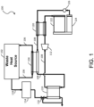
- Waste heat recovery system 100 includes a waste heat source 102 and at least one heat exchanger 104, both of which are fluidically coupled to each other for exchanging heat.
- system 100 is configured to selectively recover heat from a coolant 106, which is a low grade heat source, based on an operating condition of waste heat source 102, such as an engine.
- a coolant 106 which is a low grade heat source
- Other exemplary waste heat recovery systems are also described in the commonly assigned U.S. Patent Nos., 7,866,157 ; 8,544,274 ; and 8,627,663 , and International Application No. PCT/US15/57329 .
- Possible waste heat sources 102 include an EGR, a coolant, a charge air, a mixed EGR and charge air (mixed-charge), an engine and/or waste heat recovery oil, an exhaust, and the like.
- Waste heat source 102 can include an ICE, for example, a diesel engine, a gasoline engine, a natural gas engine, a positive displacement engine, a rotary engine, or any other suitable engine, which converts a fuel (e.g., diesel, gasoline, natural gas, biodiesel, ethanol any combination thereof or any other suitable fuel) into mechanical energy. The conversion produces heat which heats up an engine block or other housing component of the engine.
- coolant 106 is pumped through the engine block or other housing of the engine. Coolant 106 can have a sufficient heat capacity to extract a substantial portion of the heat from the engine.
- Coolant 106 can include any suitable coolant, for example, a coolant suitable for use with a diesel engine.
- Heat exchanger 104 can be, for example, a microtube or microchannel heat exchanger, and any number of combinations of microtube and microchannel heat exchangers are contemplated.
- heat exchanger 104 is constructed and arranged based on organic Rankine cycle (ORC) technologies, but can also be applied to other suitable waste heat recovery systems, such as Brayton cycle, Kalina cycle, absorption and/or adsorption cycle, and the like.
- ORC organic Rankine cycle
- heat exchanger 104 recovers heat from engines (e.g., reciprocating, turbine, or the like) and generates mechanical and/or electrical power or other suitable work (e.g., refrigeration or air conditioning, etc.) from available waste heat sources.
- microtube heat exchangers can be used for waste heat recovery components, such as components receiving waste heat from engine sources (e.g., coolant boiler, EGR boiler/superheater, tailpipe boiler, charge-air-cooler, mixed-charge-cooler, engine oil cooler, waste heat recovery oil cooler, exhaust boiler, recuperator, condenser, subcooler, and the like).
- engine sources e.g., coolant boiler, EGR boiler/superheater, tailpipe boiler, charge-air-cooler, mixed-charge-cooler, engine oil cooler, waste heat recovery oil cooler, exhaust boiler, recuperator, condenser, subcooler, and the like.
- recuperative or efficiency-improving components e.g., recuperator or waste heat recovery oil cooler
- recuperator or waste heat recovery oil cooler can also be used in association with a combustion portion of a gas turbine engine for increasing its overall efficiency.
- heat rejection components such as a condenser and/or a subcooler
- an available liquid sink such as chilled-water or for using a hydronic loop to connect the waste heat recovery condenser to an external air-cooled heat exchanger.
- system 100 provides a reduced system cost (e.g., a lower total cost of ownership and shorter payback for users), an increased performance (e.g., reduced vehicle emissions), and an easier installation in vehicles (e.g., a lower cost for system integration providing additional new applications and/or markets).
- heat exchanger 104 is fluidically coupled to waste heat source 102 and configured to extract heat from coolant 106 to heat a working fluid 108.
- Working fluid 108 can include any suitable working fluid which can extract heat from the high grade heat source and change phase, for example, vaporize.
- coolants can include water, ethanol, ethylene glycol (e.g., an antifreeze agent), water and ethylene glycol mixture, oils, or any other suitable coolant.
- the coolant can include additives such as corrosion inhibitors, antifoam agents, dyes, and/or other additives.
- Suitable additives can include phosphates, silicates, borates, carboxylates, any other suitable additive or a combination thereof.
- the working fluid can include, for example, Genetron ® R-245fa from Honeywell, low-GWP alternatives of existing refrigerant based working fluids, such as R-1233zd(e) or the like, Therminol ® , Dowtherm J TM from Dow Chemical Co., Fluorinol ® from American Nickeloid, toluene, dodecane, isododecane, methylundecane, neopentane, neopentane, octane, water/methanol mixtures, ethanol steam, and other fluids suitable for the anticipated temperature ranges and for the materials used in the various described devices and systems, such as hydrocarbon based working fluids or hydrofluorocarbon based working fluids, may be used.
- Genetron ® R-245fa from Honeywell
- low-GWP alternatives of existing refrigerant based working fluids such as R-1233zd(e) or the like
- Therminol ® Dowtherm J TM
- Heat exchanger 104 can include any suitable heat exchanger(s) which can extract heat from coolant 106 and communicate the heat to working fluid 108.
- a temperature of coolant 106 can be sufficient to preheat working fluid 108 and cause working fluid 108 to change phase (e.g., evaporate).
- heat exchanger 104 is configured to allow coolant 106 to flow through in a first direction, for example left to right along a longitudinal axis of heat exchanger 104 as shown in FIG. 1 . Further, working fluid 108 flows through heat exchanger 104 in a second direction which is opposite the first direction, for example, from right to left.
- heat exchanger 104 can be configured so that the first direction is the same as the second direction, i.e., coolant 106 and working fluid 108 flows through heat exchanger 104 parallel to each other in the same direction.
- coolant 106 and working fluid 108 flows through heat exchanger 104 parallel to each other in the same direction.
- Other suitable arrangements are also contemplated to suit different applications.
- Heat exchanger 104 is also fluidically coupled to an exhaust boiler 110 configured to receive preheated working fluid 108 from heat exchanger 104 and to evaporate working fluid 108 and communicate the evaporated working fluid to an energy conversion device 112.
- Exhaust boiler 110 receives heat from an after-treatment device 114 via a control valve 116 (e.g., a three-way check valve) using tailpipe exhaust 118 generated from waste heat source 102.
- control valve 116 e.g., a three-way check valve
- heat exchanger 104 is configured to extract heat from a high grade heat source such as, an exhaust gas (e.g., diesel exhaust gas) from waste heat source 102, or a compressed intake gas communicated into waste heat source 102.
- the high grade heat source has a substantially higher peak temperature (e.g., in the range of about 550 degrees Fahrenheit to about 1,300 degrees Fahrenheit in certain embodiments) than a peak temperature of the coolant (e.g., in the range of about 180 degrees Fahrenheit to about 230 degrees Fahrenheit in certain embodiments).
- Energy conversion device 112 receives the vaporized working fluid 108 and is configured to generate energy for performing additional work or transferring the energy to another device or system using the heat recovered from waste heat source 102.
- energy conversion device 112 can include a turbine, piston, scroll, screw, gerotor or other type of expander devices that moves (e.g., rotates) as a result of expanding working fluid vapor to provide additional work.
- the power of expander devices can be extracted mechanically via a gear or a belt drive or using an electric generator.
- the additional work can be fed into the engine's driveline to supplement the engine's power either mechanically or electrically (e.g., by turning a generator), or it can be used to drive a generator and power electrical devices, parasitic devices or a storage battery (not shown).
- energy conversion device 112 can be used to transfer energy from one system to another system (e.g., to transfer heat energy from waste heat recovery system 100 to a fluid for a heating system).
- recuperator 120 configured to receive the expanded working fluid 108 from energy conversion device 112 and communicate at least a portion of the preheated working fluid 108 to heat exchanger 104.
- Recuperator 120 is fluidically coupled to a condenser 122 (e.g., a multi-pass condenser) and a sub-cooler 124 which is also fluidically coupled to recuperator 120.
- Condenser 122 and sub-cooler 124 are configured to receive working fluid 108 from recuperator 120 and condense working fluid 108 into a liquid phase.
- a feed pump 126 is fluidically coupled to sub-cooler 124 and configured to pump working fluid 108 through a liquid circuit of waste heat recovery system 100. Additional examples of waste heat recovery system 100 are shown in FIGS. 2-4 in greater detail.
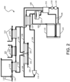
- FIG. 2 another exemplary waste heat recovery system 200 according to an embodiment of the present invention is shown.
- an EGR superheater 202 and an EGR boiler 204 are fluidically coupled together to extract heat from one or more waste heat sources for preheating or superheating working fluid 108.
- EGR superheater 202 and EGR boiler 204 are separate units, but they can be combined into one assembly to suit the application.
- an EGR gas 206 is received by EGR superheater 202 and communicated into EGR boiler 204 for heat exchange operation.
- a coolant boiler 208 is fluidically coupled to exhaust boiler 110 and a pre-charge air cooler 210.
- Coolant boiler 208 is configured to extract heat from coolant 106 to heat working fluid 108.
- Coolant boiler 208 is also configured to receive preheated working fluid 108 from pre-charge air cooler 210 and deliver working fluid 108 to exhaust boiler 110.
- Pre-charge air cooler 210 receives a charge air 212 from, for example, a turbocharger (not shown).
- working fluid 108 is fluidically communicated from pre-charge air cooler 210 to EGR superheater 202 via exhaust boiler 110 and coolant boiler 208.
- an arrangement sequence of pre-charge air cooler 210, coolant boiler 208, and exhaust boiler 110 is variable depending on the application. Other suitable sequences are also contemplated.
- recuperator 120 is configured to receive the expanded working fluid 108 from energy conversion device 112 and communicate at least a portion of the preheated working fluid 108 to pre-charge air cooler 210.
- Recuperator 120 is fluidically coupled to an elevated receiver 214 and a valve manifold 216.
- Condenser 122 and sub-cooler 124 are also fluidically coupled to recuperator 120.
- Condenser 122 and sub-cooler 124 can be configured to receive working fluid 108 from recuperator 120 and/or valve manifold 216, and condense working fluid 108 into a liquid phase.
- Feed pump 126 is fluidically coupled to sub-cooler 124 and valve manifold 216, and configured to pump working fluid 108 through the waste heat recovery system liquid circuit.
- a filter 218 is disposed downstream of feed pump 126 and upstream of valve manifold 216.
- Filter 218 is configured to remove particulates or contaminants from working fluid 108.
- a drier is also used in conjunction with filter 218 to suit different applications.
- vaporization of working fluid 108 by exhaust boiler 110, coolant boiler 208, and pre-charge air cooler 210 can reduce the amount of energy required by EGR superheater 202 to heat working fluid 108 such that it completes phase change and superheats.
- working fluid 108 can be vaporized in exhaust boiler 110 and EGR superheater 202 can be used only to superheat the vaporized working fluid 108. This may increase the power output of waste heat recovery system 200 and/or allow superheating of working fluid 108 to even higher temperatures, increasing the amount of work that can be extracted by energy conversion device 112 from working fluid 108.
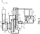
- waste heat recovery system 300 instead of having separate EGR superheater 202 and EGR boiler 204 as shown in FIG. 2 , an integrated EGR boiler/superheater 302 is used to extract heat from coolant 106 to heat working fluid 108.
- waste heat recovery system 300 includes a pump 304 in fluid communication with an engine 306 and a radiator 308 for circulating coolant 106 in the vehicle.
- coolant boiler 208 is fluidically coupled to integrated EGR boiler/superheater 302 and engine 306, using a thermostat 310 and a coolant control valve 312.
- System 300 is configured to selectively recover heat from coolant 106 based on an operating condition of engine 306.
- Radiator 308 is configured to receive heated coolant 106 from engine 306 and is further configured to cool coolant 106. Cooled coolant 106 can then be communicated back to engine 306. Radiator 308 can include any suitable radiator, for example, an air cooled radiator. Blowers or fans (not shown) can be used and configured to force air through radiator 308 to cool coolant 106 flowing through radiator 308.
- Pump 304 is fluidically coupled to engine 306 and configured to pump coolant 106 through engine 306, for example, through an engine block or other housing of engine 306 to cool engine 306. Further, pump 304 is fluidically coupled to radiator 308 to receive cooled coolant 106 from radiator 308.
- Thermostat 310 is fluidically coupled to engine 306 and pump 304.
- Thermostat 310 is configured to direct coolant 106 towards the cooling circuit which includes radiator 308 and coolant boiler 208 when engine 306 has reached a predetermined temperature.
- thermostat 310 can include a temperature activated valve. When a temperature of engine 306 is below a predetermined engine temperature threshold, for example, at ambient temperature, on an engine startup, a valve of thermostat 310 is closed, blocking any flow of coolant 106 to the cooling circuit and routing coolant flow back into engine 306. This allows engine 306 to warm up rapidly during engine warmup.
- the valve of thermostat 310 opens, allowing coolant 106 to flow from engine 306 to the cooling circuit (e.g., radiator and/or coolant heat exchanger).
- the cooling circuit e.g., radiator and/or coolant heat exchanger
- vaporized working fluid 108 is communicated to energy conversion device 112 which is configured to perform additional work or transfer energy to another device or system.
- a turbine assembly 314 is fluidically coupled to energy conversion device 112 and is configured to generate energy or power as a result of expanding working fluid vapor.
- the generated power can be supplied to the engine's driveline to supplement the engine's power either mechanically or electrically (e.g., by turning a generator), or it can be used to drive a generator and power electrical devices, parasitic devices or a storage battery (not shown).
- energy conversion device 112 can be used to transfer energy or power from one system to another system.
- Another feed pump 316 is fluidically coupled to turbine assembly 314 and configured to pump working fluid 108 to recuperator 120.
- a bypass valve 318 can also be fluidically coupled to feed pump 316 to bypass the fluid flow of working fluid 108 as shown in FIG. 3 .
- a drain valve 320 is fluidically coupled to subcooler 124 for receiving working fluid 108 from receiver 214. Additional control valves are also contemplated in various locations of the liquid circuit of system 300 to suit different applications. For example, a check valve 322 is configured to selectively redirect working fluid 108 received from subcooler 124 to receiver 214.
- An EGR temperature valve 324 is configured to selectively redirect working fluid 108 to integrated EGR boiler/superheater 302 based on the temperature of working fluid 108.
- EGR temperature valve 324 can include an active thermostat (e.g., a temperature activated valve), or any other active valve. In various embodiments, these control valves include two- or three-way valves depending on applications.
- one or more oil drain / vapor vent conduits 326 are fluidically coupled to turbine assembly 314 and recuperator 120. In one example, a first conduit 326 fluidically connects turbine assembly 314 to an inlet of recuperator 120. In another example, a second conduit 326 fluidically connects turbine assembly 314 to an outlet of recuperator 120. Other suitable arrangements are also contemplated to suit different applications.
- FIG. 4 another exemplary waste heat recovery system 400 according to an embodiment of the present invention s shown.
- integrated EGR boiler/superheater 302 shown in FIG. 3 is fluidically coupled to exhaust boiler 110 shown in FIG. 1 to extract heat from tailpipe exhaust 118 to heat working fluid 108.
- An arrangement of recuperator 120, condenser 122, sub-cooler 124, receiver 214, and valve manifold 216 of system 200 shown in FIG. 2 is similarly employed in system 400.
- a turbine/gearbox assembly 402 includes energy conversion device 112, turbine assembly 314, an oil tank 404, an oil cooler 406, and an oil pump/filter 408.
- turbine assembly 314 includes a gearbox and a drive clutch lubricated by gearbox oil, and the gearbox oil is drained into oil tank 404.
- Oil cooler 406 is fluidically coupled to turbine assembly 314 to receive the gearbox oil and it is communicated into oil tank 404.
- the received gearbox oil in oil tank 404 is supplied back to turbine assembly 314 using oil pump/filter 408.
- a gearbox vent conduit 410 fluidly connects oil tank 404 and energy conversion device 112, and an oil scraper line 412 fluidly connects energy conversion device 112 and turbine assembly 314.
- Other suitable arrangements of components shown in turbine/gearbox assembly 402 are also contemplated to suit different applications.
Landscapes
- Engineering & Computer Science (AREA)
- Chemical & Material Sciences (AREA)
- Combustion & Propulsion (AREA)
- Mechanical Engineering (AREA)
- General Engineering & Computer Science (AREA)
- Physics & Mathematics (AREA)
- Thermal Sciences (AREA)
- Engine Equipment That Uses Special Cycles (AREA)
Description
- The present disclosure generally relates to energy recovery systems, and more specifically to waste heat recovery systems with heat exchangers for internal combustion engines.
- Internal combustion engines are available in a variety of different configurations. Some are spark-ignited wherein a mixture of air and fuel (e.g., gasoline) is delivered to each of the engine's cylinders and ignited by, for example, a spark plug at a specific time during the engine cycle to cause combustion. The combustion moves a piston in the cylinder, causing rotation of a crankshaft, which delivers power to a drivetrain. Other engines are compression-ignited wherein a mixture of air and fuel (e.g., diesel) is delivered to each of cylinder which combusts as a result of compression of the mixture in the cylinder during the compression stroke of the piston. During operation, the engines often generate more heat and energy than needed for operation of the piston, the crankshaft, and the drivetrain.
- Conventional waste heat recovery systems to recover heat generated by the engines that would otherwise be lost through cooling and heat rejection provide means to improve engine efficiency. Heat is generally recovered from sources of high temperature, for example, the exhaust gas produced by the internal combustion engine (ICE), or compressed intake gas. Such high grade waste heat recovery systems include components which are configured to extract the heat from the high temperature source. These components can include exhaust gas recirculation (EGR) boilers, pre-charge air coolers (pre-CAC), exhaust system heat exchangers, or other components configured to extract heat from the high grade source of heat.
- However, the conventional waste heat recovery systems do not offer higher levels of performance and are not as compact, or as easily integrated into existing applications. Drawbacks of the conventional waste heat recovery systems include high weight, high manufacturing and operation cost, and difficulties in assembly and fabrication. Accordingly, it is desirable to develop a waste heat recovery system that addresses one or more of the drawbacks mentioned above.
US 2016/0326914 A1 ,WO 2016/069455 A1 ,US 2016/061059 A1 , andUS 2015/176466 A1 describe internal combustion engines with waste heat recovery systems to extract heat from an engine and to generate power from the extracted heat energy by means of an energy conversion device of the waste heat recovery system.US 2014/230761 A1 describes an engine, in particular an internal combustion engine, with a recirculation of carbon dioxide which exchanges energy with the engine. - The invention is defined by the features of claim 1 and provides a waste heat recovery system. At least one heat exchanger is fluidically coupled to a waste heat source and is configured for selectively recovering heat from the waste heat source to heat a working fluid. At least one energy conversion device is fluidically coupled to the at least one heat exchanger and is configured to receive the working fluid and to generate an energy for performing work or transferring the energy to another device using the heat recovered from the waste heat source. A condenser is fluidically coupled to the at least one energy conversion device and is configured to receive the working fluid from the at least one energy conversion device and to condense the working fluid into a liquid phase. A recuperator is fluidically coupled to the at least one energy conversion device and is configured to receive the working fluid from the at least one energy conversion device and to communicate at least a portion of the working fluid to the at least one heat exchanger.
- In one aspect of this embodiment, the at least one energy conversion device provides an electric or mechanical power using the generated energy. In one example, the energy conversion device can be one of: a piston expander, a screw expander, a scroll expander, a gerotor expander, and a turbine expander. In another example, the energy conversion device includes at least one of: a plurality of working fluid inlets and a plurality of working fluid outlets. The working fluid includes at least one of: water, ethanol, toluene, ethylene glycol, water and ethylene glycol mixture, oil, R245fa, low GWP replacements for R245fa, R1233zd(e), other hydrocarbon based working fluid, other hydrofluorocarbon based working fluids, oil, any mixtures of these working fluids. The at least one heat exchanger or the recuperator includes at least one of: a plurality of microtubes and a plurality of microchannels. The waste heat source includes at least one of: an exhaust, a recirculated exhaust (EGR), a coolant, a lubricant, a charge air, and any combination of the aforementioned sources (e.g., a mixed-charge, which is EGR and charge air mixed together).
- In another aspect of this embodiment, an exhaust boiler is fluidically coupled to the at least one heat exchanger and is configured to receive the working fluid from the at least one heat exchanger and to evaporate the working fluid and communicate the evaporated working fluid to the at least one energy conversion device. The exhaust boiler is configured to extract the heat from an exhaust generated from an after-treatment device to heat the working fluid.
- In yet another aspect of this embodiment, the recuperator includes a plurality of microtubes. The recuperator is fluidically coupled to the condenser, the at least one energy conversion device, and the at least one heat exchanger. The condenser is fluidically coupled to a sub-cooler which is fluidically coupled to the recuperator via a feed pump.
- In another embodiment of the present disclosure, a waste heat recovery system has an exhaust gas recirculation (EGR) superheater and an EGR boiler, both being fluidically coupled together to a waste heat source and configured for selectively recovering heat from the waste heat source to heat a working fluid. At least one energy conversion device is fluidically coupled to the EGR superheater and the EGR boiler, and is configured to receive the working fluid and to generate an energy for performing work or transferring the energy to another device using the heat recovered from the waste heat source. A condenser is fluidically coupled to the at least one energy conversion device and is configured to receive the working fluid from the at least one energy conversion device and to condense the working fluid into a liquid phase, wherein at least one of the EGR superheater and the EGR boiler includes a plurality of microtubes.
- In one aspect of this embodiment, the waste heat source includes at least one of: an exhaust, a recirculated exhaust (EGR), a coolant, a lubricant, a charge air, and any combination of the aforementioned sources. The heat from the exhaust is recovered by an exhaust boiler, the heat from the coolant is recovered by a coolant boiler, and the heat from the charge air is recovered by a charge cooler or a pre-charge air cooler. For example, the "charge cooler" would do all the cooling for the incoming engine air, and the "pre-charge cooler" would only do a portion of the cooling. The working fluid is fluidically communicated from the pre-charge air cooler to the EGR superheater via the exhaust boiler and the coolant boiler.
- In another aspect of this embodiment, a recuperator is fluidically coupled to the at least one energy conversion device and is configured to receive the working fluid from the at least one energy conversion device and to communicate at least a portion of the working fluid to the condenser.
- In yet another embodiment of the present disclosure, the waste heat recovery system includes an integrated exhaust gas recirculation (EGR) boiler/superheater fluidically coupled to a coolant boiler and configured for selectively recovering heat from the coolant boiler to heat a working fluid. At least one energy conversion device is fluidically coupled to the integrated EGR boiler/superheater and is configured to receive the working fluid and to generate an energy for performing work or transferring the energy to another device using the heat recovered from the coolant boiler. A condenser is fluidically coupled to the at least one energy conversion device and is configured to receive the working fluid from the at least one energy conversion device and to condense the working fluid into a liquid phase.
- In one aspect of the embodiment, the coolant boiler is connected to a pump in fluid communication with an engine and a radiator for circulating a coolant. In another aspect of the embodiment, a turbine assembly is fluidically coupled to the at least one energy conversion device and is configured to generate the energy using the working fluid. The turbine assembly is fluidically coupled to the condenser for receiving the working fluid from the condenser. The turbine assembly includes a gearbox and a drive clutch, and is fluidically coupled to at least one of: an oil tank, an oil cooler, and an oil pump. The EGR boiler/superheater includes a plurality of microtubes.
- In yet another embodiment of the present disclosure, a waste heat recovery system includes at least one heat exchanger having a plurality of microtubes and fluidically coupled to a waste heat source and configured for selectively recovering heat from the waste heat source to heat a working fluid. At least one energy conversion device is fluidically coupled to the at least one heat exchanger and is configured to receive the working fluid and to generate an energy for performing work or transferring the energy to another device using the heat recovered from the waste heat source. A condenser is fluidically coupled to the at least one energy conversion device and is configured to receive the working fluid from the at least one energy conversion device and to condense the working fluid into a liquid phase.
- While multiple embodiments are disclosed, still other embodiments of the present disclosure will become apparent to those skilled in the art from the following detailed description, which shows and describes illustrative embodiments of the present disclosure. Accordingly, the drawings and detailed description are to be regarded as illustrative in nature and not restrictive.
- The above-mentioned and other features of this disclosure and the manner of obtaining them will become more apparent and the disclosure itself will be better understood by reference to the following description of embodiments of the present disclosure taken in conjunction with the accompanying drawings, wherein:
-
FIG. 1 is a schematic block diagram of a waste heat recovery system with a heat exchanger in accordance with embodiments of the present invention; -
FIG. 2 is a schematic block diagram of a first example of the waste heat recovery system shown inFIG. 1 in accordance with embodiments of the present invention; -
FIG. 3 is a schematic block diagram of a second example of the waste heat recovery system shown inFIG. 1 in accordance with embodiments of the present invention; and -
FIG. 4 is a schematic block diagram of a third example of the waste heat recovery system shown inFIG. 1 in accordance with embodiments of the present invention; - While the present disclosure is amenable to various modifications and alternative forms, specific embodiments have been shown by way of example in the drawings and are described in detail below. The intention, however, is not to limit the present disclosure to the particular embodiments described. On the contrary, the present disclosure is intended to cover all modifications, equivalents, and alternatives falling within the scope of the present invention as defined by the appended claims.
- In the following detailed description, reference is made to the accompanying drawings which form a part hereof, and in which is shown by way of illustration specific embodiments in which the present invention is practiced. These embodiments are described in sufficient detail to enable those skilled in the art to practice the present invention, and it is to be understood that other embodiments can be utilized and that structural changes can be made without departing from the scope of the present invention.
- Examples of the waste heat recovery system described herein relate to waste heat recovery systems for use with engines using one or more heat exchangers, such as a coolant boiler. Examples of the waste heat recovery system described herein for extracting heat from a coolant can provide several benefits including, for example, (1) enhancing engine efficiency and fuel economy; (2) reducing an overall size of the recovery systems; (3) improving operation and/or manufacturing cost of the recovery systems; (4) extracting heat from the coolant which is otherwise lost to the environment for preheating and evaporating the working fluid; (5) selectively controlling the flow of coolant to either a heat exchanger or a radiator; and (6) preheating and evaporating a working fluid used in conjunction with high grade waste heat thereby increasing the power output of the waste heat recovery system.
- Referring now to
FIG. 1 , an exemplary wasteheat recovery system 100 according to an embodiment of the present invention is shown. Wasteheat recovery system 100 includes awaste heat source 102 and at least oneheat exchanger 104, both of which are fluidically coupled to each other for exchanging heat. For example,system 100 is configured to selectively recover heat from acoolant 106, which is a low grade heat source, based on an operating condition ofwaste heat source 102, such as an engine. Other exemplary waste heat recovery systems are also described in the commonly assignedU.S. Patent Nos., 7,866,157 ;8,544,274 ; and8,627,663 , and International Application No.PCT/US15/57329 . Possiblewaste heat sources 102 include an EGR, a coolant, a charge air, a mixed EGR and charge air (mixed-charge), an engine and/or waste heat recovery oil, an exhaust, and the like. -
Waste heat source 102 can include an ICE, for example, a diesel engine, a gasoline engine, a natural gas engine, a positive displacement engine, a rotary engine, or any other suitable engine, which converts a fuel (e.g., diesel, gasoline, natural gas, biodiesel, ethanol any combination thereof or any other suitable fuel) into mechanical energy. The conversion produces heat which heats up an engine block or other housing component of the engine. To cool the engine,coolant 106 is pumped through the engine block or other housing of the engine.Coolant 106 can have a sufficient heat capacity to extract a substantial portion of the heat from the engine.Coolant 106 can include any suitable coolant, for example, a coolant suitable for use with a diesel engine. -
Heat exchanger 104 can be, for example, a microtube or microchannel heat exchanger, and any number of combinations of microtube and microchannel heat exchangers are contemplated. In another example,heat exchanger 104 is constructed and arranged based on organic Rankine cycle (ORC) technologies, but can also be applied to other suitable waste heat recovery systems, such as Brayton cycle, Kalina cycle, absorption and/or adsorption cycle, and the like. In some embodiments,heat exchanger 104 recovers heat from engines (e.g., reciprocating, turbine, or the like) and generates mechanical and/or electrical power or other suitable work (e.g., refrigeration or air conditioning, etc.) from available waste heat sources. - For example, microtube heat exchangers can be used for waste heat recovery components, such as components receiving waste heat from engine sources (e.g., coolant boiler, EGR boiler/superheater, tailpipe boiler, charge-air-cooler, mixed-charge-cooler, engine oil cooler, waste heat recovery oil cooler, exhaust boiler, recuperator, condenser, subcooler, and the like). In another example, recuperative or efficiency-improving components (e.g., recuperator or waste heat recovery oil cooler) can also be used in association with a combustion portion of a gas turbine engine for increasing its overall efficiency. In yet another example, heat rejection components, such as a condenser and/or a subcooler, are used for employing an available liquid sink, such as chilled-water or for using a hydronic loop to connect the waste heat recovery condenser to an external air-cooled heat exchanger. In this configuration,
system 100 provides a reduced system cost (e.g., a lower total cost of ownership and shorter payback for users), an increased performance (e.g., reduced vehicle emissions), and an easier installation in vehicles (e.g., a lower cost for system integration providing additional new applications and/or markets). - In
FIG. 1 ,heat exchanger 104 is fluidically coupled towaste heat source 102 and configured to extract heat fromcoolant 106 to heat a workingfluid 108. Working fluid 108 can include any suitable working fluid which can extract heat from the high grade heat source and change phase, for example, vaporize. Such coolants can include water, ethanol, ethylene glycol (e.g., an antifreeze agent), water and ethylene glycol mixture, oils, or any other suitable coolant. Furthermore, the coolant can include additives such as corrosion inhibitors, antifoam agents, dyes, and/or other additives. Suitable additives can include phosphates, silicates, borates, carboxylates, any other suitable additive or a combination thereof. For example, the working fluid can include, for example, Genetron® R-245fa from Honeywell, low-GWP alternatives of existing refrigerant based working fluids, such as R-1233zd(e) or the like, Therminol®, Dowtherm J™ from Dow Chemical Co., Fluorinol® from American Nickeloid, toluene, dodecane, isododecane, methylundecane, neopentane, neopentane, octane, water/methanol mixtures, ethanol steam, and other fluids suitable for the anticipated temperature ranges and for the materials used in the various described devices and systems, such as hydrocarbon based working fluids or hydrofluorocarbon based working fluids, may be used. -
Heat exchanger 104 can include any suitable heat exchanger(s) which can extract heat fromcoolant 106 and communicate the heat to workingfluid 108. A temperature ofcoolant 106 can be sufficient to preheat workingfluid 108 andcause working fluid 108 to change phase (e.g., evaporate). In this example,heat exchanger 104 is configured to allowcoolant 106 to flow through in a first direction, for example left to right along a longitudinal axis ofheat exchanger 104 as shown inFIG. 1 . Further, workingfluid 108 flows throughheat exchanger 104 in a second direction which is opposite the first direction, for example, from right to left. In other embodiments,heat exchanger 104 can be configured so that the first direction is the same as the second direction, i.e.,coolant 106 and workingfluid 108 flows throughheat exchanger 104 parallel to each other in the same direction. Other suitable arrangements are also contemplated to suit different applications. -
Heat exchanger 104 is also fluidically coupled to anexhaust boiler 110 configured to receivepreheated working fluid 108 fromheat exchanger 104 and to evaporate workingfluid 108 and communicate the evaporated working fluid to anenergy conversion device 112.Exhaust boiler 110 receives heat from an after-treatment device 114 via a control valve 116 (e.g., a three-way check valve) usingtailpipe exhaust 118 generated fromwaste heat source 102. More specifically,heat exchanger 104 is configured to extract heat from a high grade heat source such as, an exhaust gas (e.g., diesel exhaust gas) fromwaste heat source 102, or a compressed intake gas communicated intowaste heat source 102. The high grade heat source has a substantially higher peak temperature (e.g., in the range of about 550 degrees Fahrenheit to about 1,300 degrees Fahrenheit in certain embodiments) than a peak temperature of the coolant (e.g., in the range of about 180 degrees Fahrenheit to about 230 degrees Fahrenheit in certain embodiments). -
Energy conversion device 112 receives the vaporized workingfluid 108 and is configured to generate energy for performing additional work or transferring the energy to another device or system using the heat recovered fromwaste heat source 102. For example,energy conversion device 112 can include a turbine, piston, scroll, screw, gerotor or other type of expander devices that moves (e.g., rotates) as a result of expanding working fluid vapor to provide additional work. For example, the power of expander devices can be extracted mechanically via a gear or a belt drive or using an electric generator. In some embodiments, the additional work can be fed into the engine's driveline to supplement the engine's power either mechanically or electrically (e.g., by turning a generator), or it can be used to drive a generator and power electrical devices, parasitic devices or a storage battery (not shown). Alternatively,energy conversion device 112 can be used to transfer energy from one system to another system (e.g., to transfer heat energy from wasteheat recovery system 100 to a fluid for a heating system). - Also included in
system 100 is arecuperator 120 configured to receive the expanded workingfluid 108 fromenergy conversion device 112 and communicate at least a portion of the preheated workingfluid 108 toheat exchanger 104.Recuperator 120 is fluidically coupled to a condenser 122 (e.g., a multi-pass condenser) and a sub-cooler 124 which is also fluidically coupled torecuperator 120.Condenser 122 and sub-cooler 124 are configured to receive workingfluid 108 fromrecuperator 120 and condense workingfluid 108 into a liquid phase. Afeed pump 126 is fluidically coupled tosub-cooler 124 and configured to pump workingfluid 108 through a liquid circuit of wasteheat recovery system 100. Additional examples of wasteheat recovery system 100 are shown inFIGS. 2-4 in greater detail. - Referring now to
FIG. 2 , another exemplary wasteheat recovery system 200 according to an embodiment of the present invention is shown. Like reference numerals represent like elements shown inFIG. 1 . In this example, instead of asingle heat exchanger 104 shown inFIG. 1 , anEGR superheater 202 and anEGR boiler 204 are fluidically coupled together to extract heat from one or more waste heat sources for preheating or superheating workingfluid 108. In one example,EGR superheater 202 andEGR boiler 204 are separate units, but they can be combined into one assembly to suit the application. For example, anEGR gas 206 is received by EGR superheater 202 and communicated intoEGR boiler 204 for heat exchange operation. Further, acoolant boiler 208 is fluidically coupled toexhaust boiler 110 and apre-charge air cooler 210.Coolant boiler 208 is configured to extract heat fromcoolant 106 to heat workingfluid 108.Coolant boiler 208 is also configured to receivepreheated working fluid 108 frompre-charge air cooler 210 and deliver workingfluid 108 toexhaust boiler 110.Pre-charge air cooler 210 receives acharge air 212 from, for example, a turbocharger (not shown). As such, workingfluid 108 is fluidically communicated frompre-charge air cooler 210 to EGR superheater 202 viaexhaust boiler 110 andcoolant boiler 208. However, an arrangement sequence ofpre-charge air cooler 210,coolant boiler 208, andexhaust boiler 110 is variable depending on the application. Other suitable sequences are also contemplated. - In this example,
recuperator 120 is configured to receive the expanded workingfluid 108 fromenergy conversion device 112 and communicate at least a portion of the preheated workingfluid 108 topre-charge air cooler 210.Recuperator 120 is fluidically coupled to anelevated receiver 214 and avalve manifold 216.Condenser 122 and sub-cooler 124 are also fluidically coupled torecuperator 120.Condenser 122 and sub-cooler 124 can be configured to receive workingfluid 108 fromrecuperator 120 and/orvalve manifold 216, and condense workingfluid 108 into a liquid phase.Feed pump 126 is fluidically coupled tosub-cooler 124 andvalve manifold 216, and configured to pump workingfluid 108 through the waste heat recovery system liquid circuit. Afilter 218 is disposed downstream offeed pump 126 and upstream ofvalve manifold 216.Filter 218 is configured to remove particulates or contaminants from workingfluid 108. In some embodiments, a drier is also used in conjunction withfilter 218 to suit different applications. - During operation, vaporization of working
fluid 108 byexhaust boiler 110,coolant boiler 208, andpre-charge air cooler 210 can reduce the amount of energy required by EGR superheater 202 to heat workingfluid 108 such that it completes phase change and superheats. In this arrangement, workingfluid 108 can be vaporized inexhaust boiler 110 andEGR superheater 202 can be used only to superheat the vaporized workingfluid 108. This may increase the power output of wasteheat recovery system 200 and/or allow superheating of workingfluid 108 to even higher temperatures, increasing the amount of work that can be extracted byenergy conversion device 112 from workingfluid 108. - Referring now to
FIG. 3 , another exemplary wasteheat recovery system 300 according to an embodiment of the present invention s shown. Like reference numerals represent like elements shown inFIGS. 1-2 . In this example, instead of havingseparate EGR superheater 202 andEGR boiler 204 as shown inFIG. 2 , an integrated EGR boiler/superheater 302 is used to extract heat fromcoolant 106 to heat workingfluid 108. Also, wasteheat recovery system 300 includes apump 304 in fluid communication with anengine 306 and aradiator 308 for circulatingcoolant 106 in the vehicle. In some embodiments,coolant boiler 208 is fluidically coupled to integrated EGR boiler/superheater 302 andengine 306, using athermostat 310 and acoolant control valve 312.System 300 is configured to selectively recover heat fromcoolant 106 based on an operating condition ofengine 306. -
Radiator 308 is configured to receiveheated coolant 106 fromengine 306 and is further configured to coolcoolant 106. Cooledcoolant 106 can then be communicated back toengine 306.Radiator 308 can include any suitable radiator, for example, an air cooled radiator. Blowers or fans (not shown) can be used and configured to force air throughradiator 308 tocool coolant 106 flowing throughradiator 308.Pump 304 is fluidically coupled toengine 306 and configured to pumpcoolant 106 throughengine 306, for example, through an engine block or other housing ofengine 306 tocool engine 306. Further, pump 304 is fluidically coupled toradiator 308 to receive cooledcoolant 106 fromradiator 308. -
Thermostat 310 is fluidically coupled toengine 306 and pump 304.Thermostat 310 is configured to directcoolant 106 towards the cooling circuit which includesradiator 308 andcoolant boiler 208 whenengine 306 has reached a predetermined temperature. For example,thermostat 310 can include a temperature activated valve. When a temperature ofengine 306 is below a predetermined engine temperature threshold, for example, at ambient temperature, on an engine startup, a valve ofthermostat 310 is closed, blocking any flow ofcoolant 106 to the cooling circuit and routing coolant flow back intoengine 306. This allowsengine 306 to warm up rapidly during engine warmup. Onceengine 306 reaches or exceeds the predetermined engine temperature threshold (e.g., an operating temperature of about 200 degrees Fahrenheit), the valve ofthermostat 310 opens, allowingcoolant 106 to flow fromengine 306 to the cooling circuit (e.g., radiator and/or coolant heat exchanger). - As discussed above, vaporized working
fluid 108 is communicated toenergy conversion device 112 which is configured to perform additional work or transfer energy to another device or system. In this example, aturbine assembly 314 is fluidically coupled toenergy conversion device 112 and is configured to generate energy or power as a result of expanding working fluid vapor. The generated power can be supplied to the engine's driveline to supplement the engine's power either mechanically or electrically (e.g., by turning a generator), or it can be used to drive a generator and power electrical devices, parasitic devices or a storage battery (not shown). Alternatively,energy conversion device 112 can be used to transfer energy or power from one system to another system. - Another
feed pump 316 is fluidically coupled toturbine assembly 314 and configured to pump workingfluid 108 torecuperator 120. Abypass valve 318 can also be fluidically coupled to feedpump 316 to bypass the fluid flow of workingfluid 108 as shown inFIG. 3 . Adrain valve 320 is fluidically coupled tosubcooler 124 for receiving workingfluid 108 fromreceiver 214. Additional control valves are also contemplated in various locations of the liquid circuit ofsystem 300 to suit different applications. For example, acheck valve 322 is configured to selectively redirect workingfluid 108 received fromsubcooler 124 toreceiver 214. AnEGR temperature valve 324 is configured to selectively redirect workingfluid 108 to integrated EGR boiler/superheater 302 based on the temperature of workingfluid 108. - For example,
EGR temperature valve 324 can include an active thermostat (e.g., a temperature activated valve), or any other active valve. In various embodiments, these control valves include two- or three-way valves depending on applications. Further, one or more oil drain /vapor vent conduits 326 are fluidically coupled toturbine assembly 314 andrecuperator 120. In one example, afirst conduit 326 fluidically connectsturbine assembly 314 to an inlet ofrecuperator 120. In another example, asecond conduit 326 fluidically connectsturbine assembly 314 to an outlet ofrecuperator 120. Other suitable arrangements are also contemplated to suit different applications. - Referring now to
FIG. 4 , another exemplary wasteheat recovery system 400 according to an embodiment of the present invention s shown. Like reference numerals represent like elements shown inFIGS. 1-3 . In this example, integrated EGR boiler/superheater 302 shown inFIG. 3 is fluidically coupled toexhaust boiler 110 shown inFIG. 1 to extract heat fromtailpipe exhaust 118 to heat workingfluid 108. An arrangement ofrecuperator 120,condenser 122, sub-cooler 124,receiver 214, andvalve manifold 216 ofsystem 200 shown inFIG. 2 is similarly employed insystem 400. One aspect ofsystem 400 is that a turbine/gearbox assembly 402 includesenergy conversion device 112,turbine assembly 314, anoil tank 404, anoil cooler 406, and an oil pump/filter 408. - In some embodiments,
turbine assembly 314 includes a gearbox and a drive clutch lubricated by gearbox oil, and the gearbox oil is drained intooil tank 404.Oil cooler 406 is fluidically coupled toturbine assembly 314 to receive the gearbox oil and it is communicated intooil tank 404. The received gearbox oil inoil tank 404 is supplied back toturbine assembly 314 using oil pump/filter 408. Agearbox vent conduit 410 fluidly connectsoil tank 404 andenergy conversion device 112, and anoil scraper line 412 fluidly connectsenergy conversion device 112 andturbine assembly 314. Other suitable arrangements of components shown in turbine/gearbox assembly 402 are also contemplated to suit different applications. - Many other embodiments will be apparent to those of skill in the art upon reading and understanding the above description. For example, it is contemplated that features described in association with one embodiment are optionally employed in addition or as an alternative to features described in associate with another embodiment as long as they fall within the scope of the appended claims.
Claims (11)
- A waste heat recovery system (100) for a vehicle, comprising:at least one heat exchanger (104) fluidically coupled to a vehicle waste heat source (102) and configured for selectively recovering heat from the vehicle waste heat source (102) to heat a working fluid (108);at least one energy conversion device (112) fluidically coupled to the at least one heat exchanger (104) and configured to receive the working fluid (108) and to generate an energy for performing work or transferring the energy to another device using heat recovered from the vehicle waste heat source (102);a condenser (122) fluidically coupled to the at least one energy conversion device (112) and configured to receive the working fluid (108) from the at least one energy conversion device (112) and to condense the working fluid (108) into a liquid phase;a recuperator (120) fluidically coupled to the at least one energy conversion device (112) and configured to receive the working fluid (108) from the at least one energy conversion device (112) and to communicate at least a portion of the working fluid (108) to the at least one heat exchanger (104); characterized in that the system further comprisesan exhaust boiler (110) fluidically coupled to the at least one heat exchanger (104) and configured to receive the working fluid (108) from the at least one heat exchanger (104) and to evaporate the working fluid (108) and communicate the evaporated working fluid (108) to the at least one energy conversion device (112);wherein the exhaust boiler (110) includes a plurality of microtubes, and the condenser (122) is fluidically coupled to a sub-cooler (124) which is fluidically coupled to the recuperator (120).
- The waste heat recovery system of claim 1, wherein the at least one energy conversion device (112) provides an electric or mechanical power using the generated energy.
- The waste heat recovery system of claim 1, wherein the at least one energy conversion device (112) includes at least one of: a piston expander, a screw expander, a scroll expander, a gerotor expander, a turbine expander, a plurality of working fluid inlets and a plurality of working fluid outlets.
- The waste heat recovery system of claim 1, wherein the working fluid (108) includes at least one of: water, ethanol, toluene, ethylene glycol, water and ethylene glycol mixture, oil, R245fa, low GWP replacements for R245fa, R1233zd(e), other hydrocarbon based working fluid, other hydrofluorocarbon based working fluids, oil, any mixtures of these working fluids.
- The waste heat recovery system of claim 1, wherein the exhaust boiler (110) is configured to extract heat from an exhaust (118) provided and treated by an after-treatment device (114) to heat the working fluid (108).
- The waste heat recovery system of claim 1, wherein the recuperator (120) includes a plurality of microtubes, and the recuperator (120) is fluidically coupled to the condenser (122), the at least one energy conversion device (112), and the at least one heat exchanger (104).
- The waste heat recovery system of claim 1, wherein the sub-cooler (124) is fluidically coupled to the recuperator (120) via a feed pump (126).
- The waste heat recovery system of claim 1 , wherein the vehicle waste heat source (102) includes at least one of: an exhaust, a recirculated exhaust (EGR), a coolant, a lubricant, and a charge air.
- The waste heat recovery system of claim 8, wherein the heat from a coolant (106) is recovered by a coolant boiler (208), and heat from a charge air (212) is recovered by a charge cooler or a pre-charge air cooler (210).
- The waste heat recovery system of claim 9, wherein the working fluid (108) is fluidically communicated from the pre-charge air cooler (210) to an EGR superheater (202) via the exhaust boiler (110) and the coolant boiler (208).
- The waste heat recovery system of claim 9, wherein the recuperator (120) is configured to communicate at least a portion of the working fluid (108) to the condenser (122).
Applications Claiming Priority (2)
| Application Number | Priority Date | Filing Date | Title |
|---|---|---|---|
| US201762507449P | 2017-05-17 | 2017-05-17 | |
| PCT/US2018/031873 WO2018213080A1 (en) | 2017-05-17 | 2018-05-09 | Waste heat recovery systems with heat exchangers |
Publications (3)
| Publication Number | Publication Date |
|---|---|
| EP3610138A1 EP3610138A1 (en) | 2020-02-19 |
| EP3610138A4 EP3610138A4 (en) | 2021-05-12 |
| EP3610138B1 true EP3610138B1 (en) | 2023-10-18 |
Family
ID=64274652
Family Applications (1)
| Application Number | Title | Priority Date | Filing Date |
|---|---|---|---|
| EP18802581.1A Active EP3610138B1 (en) | 2017-05-17 | 2018-05-09 | Waste heat recovery systems with heat exchangers |
Country Status (4)
| Country | Link |
|---|---|
| US (1) | US10968785B2 (en) |
| EP (1) | EP3610138B1 (en) |
| CN (1) | CN111051654A (en) |
| WO (1) | WO2018213080A1 (en) |
Families Citing this family (10)
| Publication number | Priority date | Publication date | Assignee | Title |
|---|---|---|---|---|
| DE102017011844A1 (en) * | 2017-12-21 | 2019-06-27 | Daimler Ag | Arrangement for converting thermal energy from heat loss of an internal combustion engine |
| DE102017011851A1 (en) * | 2017-12-21 | 2019-06-27 | Daimler Ag | Arrangement for converting thermal energy from heat loss of an internal combustion engine |
| CN115298417B (en) * | 2020-03-23 | 2025-10-17 | 康明斯公司 | Multi-core heat recovery boost cooler |
| WO2021233521A1 (en) * | 2020-05-18 | 2021-11-25 | Volvo Truck Corporation | A waste heat energy recovery system for an engine |
| CN111946427B (en) * | 2020-08-12 | 2021-07-20 | 江苏金泰诺科技有限公司 | Regeneration control system and regeneration control method of organic waste gas adsorption device |
| US11415029B1 (en) * | 2021-02-12 | 2022-08-16 | Ford Global Technologies, Llc | Engine oil dilution control in automotive vehicles |
| WO2023060342A1 (en) * | 2021-10-13 | 2023-04-20 | Darryl Weflen | System and method for power generation |
| EP4293208A1 (en) * | 2022-06-13 | 2023-12-20 | Volvo Truck Corporation | An internal combustion engine system |
| CN115750015A (en) * | 2022-11-04 | 2023-03-07 | 江苏大学 | Environment-friendly waste heat comprehensive power generation system based on kalina circulation |
| US12000321B1 (en) * | 2023-02-22 | 2024-06-04 | Caterpillar Inc. | Systems and methods to reduce methane emissions associated with a lean-burn natural gas engine |
Family Cites Families (23)
| Publication number | Priority date | Publication date | Assignee | Title |
|---|---|---|---|---|
| US3103978A (en) | 1960-09-24 | 1963-09-17 | Slack & Parr Marine Ltd | Variable pitch marine screw propellers |
| US4676305A (en) * | 1985-02-11 | 1987-06-30 | Doty F David | Microtube-strip heat exchanger |
| US8528333B2 (en) * | 2007-03-02 | 2013-09-10 | Victor Juchymenko | Controlled organic rankine cycle system for recovery and conversion of thermal energy |
| US8046999B2 (en) | 2007-10-12 | 2011-11-01 | Doty Scientific, Inc. | High-temperature dual-source organic Rankine cycle with gas separations |
| US7775031B2 (en) * | 2008-05-07 | 2010-08-17 | Wood Ryan S | Recuperator for aircraft turbine engines |
| US7866157B2 (en) | 2008-05-12 | 2011-01-11 | Cummins Inc. | Waste heat recovery system with constant power output |
| US20100319346A1 (en) * | 2009-06-23 | 2010-12-23 | General Electric Company | System for recovering waste heat |
| US8544274B2 (en) | 2009-07-23 | 2013-10-01 | Cummins Intellectual Properties, Inc. | Energy recovery system using an organic rankine cycle |
| US8627663B2 (en) | 2009-09-02 | 2014-01-14 | Cummins Intellectual Properties, Inc. | Energy recovery system and method using an organic rankine cycle with condenser pressure regulation |
| US8096128B2 (en) * | 2009-09-17 | 2012-01-17 | Echogen Power Systems | Heat engine and heat to electricity systems and methods |
| US20110154822A1 (en) | 2009-12-31 | 2011-06-30 | Protz Jonathan M | Micro-scale engines, components, and methods for generating power |
| EP2553374A1 (en) * | 2010-03-29 | 2013-02-06 | Carrier Corporation | Heat exchanger |
| CN103237961B (en) * | 2010-08-05 | 2015-11-25 | 康明斯知识产权公司 | Adopt the critical supercharging cooling of the discharge of organic Rankine bottoming cycle |
| CN103180553B (en) * | 2010-08-09 | 2015-11-25 | 康明斯知识产权公司 | Comprise Waste Heat Recovery System (WHRS) and the internal-combustion engine system of rankine cycle RC subtense angle |
| DE112011104516B4 (en) * | 2010-12-23 | 2017-01-19 | Cummins Intellectual Property, Inc. | System and method for regulating EGR cooling using a Rankine cycle |
| US20140000261A1 (en) * | 2012-06-29 | 2014-01-02 | General Electric Company | Triple expansion waste heat recovery system and method |
| US9316141B2 (en) | 2013-02-15 | 2016-04-19 | Enis Pilavdzic | Engine energy management system |
| US9556778B2 (en) * | 2013-12-10 | 2017-01-31 | Cummins Inc. | Waste heat recovery system including a clutched feedpump |
| KR20150073705A (en) * | 2013-12-23 | 2015-07-01 | 현대자동차주식회사 | System of recycling exhaust heat from internal combustion engine |
| WO2016069455A1 (en) * | 2014-10-27 | 2016-05-06 | Cummins, Inc. | System and method of low grade heat utilization for a waste heat recovery system |
| US20160326914A1 (en) * | 2015-05-05 | 2016-11-10 | Cummins, Inc. | Waste heat recovery hybrid power drive |
| EP3103978A1 (en) * | 2015-06-09 | 2016-12-14 | Perkins Engines Company Limited | A selective catalytic reduction system |
| US10914228B2 (en) * | 2016-11-15 | 2021-02-09 | Cummins Inc. | Waste heat recovery with active coolant pressure control system |
-
2018
- 2018-05-09 CN CN201880032498.6A patent/CN111051654A/en active Pending
- 2018-05-09 EP EP18802581.1A patent/EP3610138B1/en active Active
- 2018-05-09 WO PCT/US2018/031873 patent/WO2018213080A1/en not_active Ceased
- 2018-05-09 US US16/614,659 patent/US10968785B2/en active Active
Also Published As
| Publication number | Publication date |
|---|---|
| US10968785B2 (en) | 2021-04-06 |
| EP3610138A4 (en) | 2021-05-12 |
| CN111051654A (en) | 2020-04-21 |
| WO2018213080A1 (en) | 2018-11-22 |
| EP3610138A1 (en) | 2020-02-19 |
| US20200191020A1 (en) | 2020-06-18 |
Similar Documents
| Publication | Publication Date | Title |
|---|---|---|
| EP3610138B1 (en) | Waste heat recovery systems with heat exchangers | |
| US7536998B2 (en) | Drive unit having thermal recovery | |
| Kim et al. | Single-loop organic Rankine cycles for engine waste heat recovery using both low-and high-temperature heat sources | |
| US11125139B2 (en) | Waste heat recovery vehicle cooling optimization | |
| US8919123B2 (en) | Waste heat recovery system with partial recuperation | |
| EP1702141B1 (en) | Organic rankine cycle system with shared heat exchanger for use with a reciprocating engine | |
| US9951659B2 (en) | Thermodynamic system in a vehicle | |
| US9074492B2 (en) | Energy recovery arrangement having multiple heat sources | |
| EP2522828A2 (en) | Organic rankine cycle systems using waste heat from charge air cooling | |
| US8650879B2 (en) | Integration of waste heat from charge air cooling into a cascaded organic rankine cycle system | |
| BRPI0905344B1 (en) | drive unit | |
| CN110439666B (en) | Engine cooling system with two thermostats including closed loop in Rankine cycle | |
| CN101408115A (en) | Thermodynamic cycle system suitable for waste heat recovery of engine for automobile | |
| WO2016069455A1 (en) | System and method of low grade heat utilization for a waste heat recovery system | |
| EP2886820A1 (en) | System of recycling exhaust heat from internal combustion engine | |
| KR20150073704A (en) | System of recycling exhaust heat from internal combustion engine | |
| EP3212899B1 (en) | Waste heat recovery integrated cooling module | |
| Zhou et al. | Application of Rankine cycle to passenger vehicle waste heat recovery-A review | |
| CN104747318A (en) | System of recycling exhaust heat from internal combustion engine | |
| WO2014096892A1 (en) | Engine arrangement comprising a separate heat storage device | |
| WO2015143323A1 (en) | Enhanced condenser for a waste heat recovery system | |
| US20170051634A1 (en) | Vehicle heat recovery system | |
| CN114370354A (en) | Waste heat recovery system and method suitable for variable working conditions of engine | |
| US11008899B2 (en) | Internal combustion engine with evaporative cooling and waste heat utilization | |
| CN111527297B (en) | A device for converting thermal energy from heat lost by an internal combustion engine |
Legal Events
| Date | Code | Title | Description |
|---|---|---|---|
| STAA | Information on the status of an ep patent application or granted ep patent |
Free format text: STATUS: THE INTERNATIONAL PUBLICATION HAS BEEN MADE |
|
| PUAI | Public reference made under article 153(3) epc to a published international application that has entered the european phase |
Free format text: ORIGINAL CODE: 0009012 |
|
| STAA | Information on the status of an ep patent application or granted ep patent |
Free format text: STATUS: REQUEST FOR EXAMINATION WAS MADE |
|
| 17P | Request for examination filed |
Effective date: 20191115 |
|
| AK | Designated contracting states |
Kind code of ref document: A1 Designated state(s): AL AT BE BG CH CY CZ DE DK EE ES FI FR GB GR HR HU IE IS IT LI LT LU LV MC MK MT NL NO PL PT RO RS SE SI SK SM TR |
|
| AX | Request for extension of the european patent |
Extension state: BA ME |
|
| DAV | Request for validation of the european patent (deleted) | ||
| DAX | Request for extension of the european patent (deleted) | ||
| RIC1 | Information provided on ipc code assigned before grant |
Ipc: F01N 5/02 20060101ALI20201223BHEP Ipc: F01K 23/10 20060101ALI20201223BHEP Ipc: F22D 1/32 20060101ALI20201223BHEP Ipc: F01K 23/02 20060101AFI20201223BHEP Ipc: F02G 5/02 20060101ALI20201223BHEP Ipc: F01N 3/10 20060101ALI20201223BHEP Ipc: F01K 23/06 20060101ALI20201223BHEP Ipc: F01K 7/42 20060101ALI20201223BHEP |
|
| A4 | Supplementary search report drawn up and despatched |
Effective date: 20210414 |
|
| RIC1 | Information provided on ipc code assigned before grant |
Ipc: F01K 23/02 20060101AFI20210408BHEP Ipc: F01K 23/10 20060101ALI20210408BHEP Ipc: F01N 3/10 20060101ALI20210408BHEP Ipc: F01N 5/02 20060101ALI20210408BHEP Ipc: F02G 5/02 20060101ALI20210408BHEP Ipc: F01K 7/42 20060101ALI20210408BHEP Ipc: F01K 23/06 20060101ALI20210408BHEP Ipc: F22D 1/32 20060101ALI20210408BHEP |
|
| RIC1 | Information provided on ipc code assigned before grant |
Ipc: F02G 5/00 20060101ALI20230320BHEP Ipc: F22D 1/32 20060101ALI20230320BHEP Ipc: F01K 23/06 20060101ALI20230320BHEP Ipc: F01K 7/42 20060101ALI20230320BHEP Ipc: F02G 5/02 20060101ALI20230320BHEP Ipc: F01N 5/02 20060101ALI20230320BHEP Ipc: F01N 3/10 20060101ALI20230320BHEP Ipc: F01K 23/10 20060101ALI20230320BHEP Ipc: F01K 23/02 20060101AFI20230320BHEP |
|
| GRAP | Despatch of communication of intention to grant a patent |
Free format text: ORIGINAL CODE: EPIDOSNIGR1 |
|
| STAA | Information on the status of an ep patent application or granted ep patent |
Free format text: STATUS: GRANT OF PATENT IS INTENDED |
|
| INTG | Intention to grant announced |
Effective date: 20230502 |
|
| RIN1 | Information on inventor provided before grant (corrected) |
Inventor name: BOAS, BRETT A. Inventor name: KOLHOUSE, J. STEVEN Inventor name: ERNST, TIMOTHY C. Inventor name: DELAHANTY, JARED C. |
|
| P01 | Opt-out of the competence of the unified patent court (upc) registered |
Effective date: 20230510 |
|
| GRAS | Grant fee paid |
Free format text: ORIGINAL CODE: EPIDOSNIGR3 |
|
| GRAA | (expected) grant |
Free format text: ORIGINAL CODE: 0009210 |
|
| STAA | Information on the status of an ep patent application or granted ep patent |
Free format text: STATUS: THE PATENT HAS BEEN GRANTED |
|
| AK | Designated contracting states |
Kind code of ref document: B1 Designated state(s): AL AT BE BG CH CY CZ DE DK EE ES FI FR GB GR HR HU IE IS IT LI LT LU LV MC MK MT NL NO PL PT RO RS SE SI SK SM TR |
|
| REG | Reference to a national code |
Ref country code: GB Ref legal event code: FG4D |
|
| REG | Reference to a national code |
Ref country code: CH Ref legal event code: EP |
|
| REG | Reference to a national code |
Ref country code: DE Ref legal event code: R096 Ref document number: 602018059649 Country of ref document: DE |
|
| REG | Reference to a national code |
Ref country code: IE Ref legal event code: FG4D |
|
| REG | Reference to a national code |
Ref country code: LT Ref legal event code: MG9D |
|
| REG | Reference to a national code |
Ref country code: NL Ref legal event code: MP Effective date: 20231018 |
|
| REG | Reference to a national code |
Ref country code: AT Ref legal event code: MK05 Ref document number: 1622662 Country of ref document: AT Kind code of ref document: T Effective date: 20231018 |
|
| PG25 | Lapsed in a contracting state [announced via postgrant information from national office to epo] |
Ref country code: NL Free format text: LAPSE BECAUSE OF FAILURE TO SUBMIT A TRANSLATION OF THE DESCRIPTION OR TO PAY THE FEE WITHIN THE PRESCRIBED TIME-LIMIT Effective date: 20231018 |
|
| PG25 | Lapsed in a contracting state [announced via postgrant information from national office to epo] |
Ref country code: GR Free format text: LAPSE BECAUSE OF FAILURE TO SUBMIT A TRANSLATION OF THE DESCRIPTION OR TO PAY THE FEE WITHIN THE PRESCRIBED TIME-LIMIT Effective date: 20240119 |
|
| PG25 | Lapsed in a contracting state [announced via postgrant information from national office to epo] |
Ref country code: IS Free format text: LAPSE BECAUSE OF FAILURE TO SUBMIT A TRANSLATION OF THE DESCRIPTION OR TO PAY THE FEE WITHIN THE PRESCRIBED TIME-LIMIT Effective date: 20240218 |
|
| PG25 | Lapsed in a contracting state [announced via postgrant information from national office to epo] |
Ref country code: LT Free format text: LAPSE BECAUSE OF FAILURE TO SUBMIT A TRANSLATION OF THE DESCRIPTION OR TO PAY THE FEE WITHIN THE PRESCRIBED TIME-LIMIT Effective date: 20231018 |
|
| PG25 | Lapsed in a contracting state [announced via postgrant information from national office to epo] |
Ref country code: AT Free format text: LAPSE BECAUSE OF FAILURE TO SUBMIT A TRANSLATION OF THE DESCRIPTION OR TO PAY THE FEE WITHIN THE PRESCRIBED TIME-LIMIT Effective date: 20231018 |
|
| PG25 | Lapsed in a contracting state [announced via postgrant information from national office to epo] |
Ref country code: ES Free format text: LAPSE BECAUSE OF FAILURE TO SUBMIT A TRANSLATION OF THE DESCRIPTION OR TO PAY THE FEE WITHIN THE PRESCRIBED TIME-LIMIT Effective date: 20231018 |
|
| PG25 | Lapsed in a contracting state [announced via postgrant information from national office to epo] |
Ref country code: LT Free format text: LAPSE BECAUSE OF FAILURE TO SUBMIT A TRANSLATION OF THE DESCRIPTION OR TO PAY THE FEE WITHIN THE PRESCRIBED TIME-LIMIT Effective date: 20231018 Ref country code: IS Free format text: LAPSE BECAUSE OF FAILURE TO SUBMIT A TRANSLATION OF THE DESCRIPTION OR TO PAY THE FEE WITHIN THE PRESCRIBED TIME-LIMIT Effective date: 20240218 Ref country code: GR Free format text: LAPSE BECAUSE OF FAILURE TO SUBMIT A TRANSLATION OF THE DESCRIPTION OR TO PAY THE FEE WITHIN THE PRESCRIBED TIME-LIMIT Effective date: 20240119 Ref country code: ES Free format text: LAPSE BECAUSE OF FAILURE TO SUBMIT A TRANSLATION OF THE DESCRIPTION OR TO PAY THE FEE WITHIN THE PRESCRIBED TIME-LIMIT Effective date: 20231018 Ref country code: BG Free format text: LAPSE BECAUSE OF FAILURE TO SUBMIT A TRANSLATION OF THE DESCRIPTION OR TO PAY THE FEE WITHIN THE PRESCRIBED TIME-LIMIT Effective date: 20240118 Ref country code: AT Free format text: LAPSE BECAUSE OF FAILURE TO SUBMIT A TRANSLATION OF THE DESCRIPTION OR TO PAY THE FEE WITHIN THE PRESCRIBED TIME-LIMIT Effective date: 20231018 Ref country code: PT Free format text: LAPSE BECAUSE OF FAILURE TO SUBMIT A TRANSLATION OF THE DESCRIPTION OR TO PAY THE FEE WITHIN THE PRESCRIBED TIME-LIMIT Effective date: 20240219 |
|
| PG25 | Lapsed in a contracting state [announced via postgrant information from national office to epo] |
Ref country code: SE Free format text: LAPSE BECAUSE OF FAILURE TO SUBMIT A TRANSLATION OF THE DESCRIPTION OR TO PAY THE FEE WITHIN THE PRESCRIBED TIME-LIMIT Effective date: 20231018 Ref country code: RS Free format text: LAPSE BECAUSE OF FAILURE TO SUBMIT A TRANSLATION OF THE DESCRIPTION OR TO PAY THE FEE WITHIN THE PRESCRIBED TIME-LIMIT Effective date: 20231018 Ref country code: PL Free format text: LAPSE BECAUSE OF FAILURE TO SUBMIT A TRANSLATION OF THE DESCRIPTION OR TO PAY THE FEE WITHIN THE PRESCRIBED TIME-LIMIT Effective date: 20231018 Ref country code: NO Free format text: LAPSE BECAUSE OF FAILURE TO SUBMIT A TRANSLATION OF THE DESCRIPTION OR TO PAY THE FEE WITHIN THE PRESCRIBED TIME-LIMIT Effective date: 20240118 Ref country code: LV Free format text: LAPSE BECAUSE OF FAILURE TO SUBMIT A TRANSLATION OF THE DESCRIPTION OR TO PAY THE FEE WITHIN THE PRESCRIBED TIME-LIMIT Effective date: 20231018 Ref country code: HR Free format text: LAPSE BECAUSE OF FAILURE TO SUBMIT A TRANSLATION OF THE DESCRIPTION OR TO PAY THE FEE WITHIN THE PRESCRIBED TIME-LIMIT Effective date: 20231018 |
|
| PG25 | Lapsed in a contracting state [announced via postgrant information from national office to epo] |
Ref country code: DK Free format text: LAPSE BECAUSE OF FAILURE TO SUBMIT A TRANSLATION OF THE DESCRIPTION OR TO PAY THE FEE WITHIN THE PRESCRIBED TIME-LIMIT Effective date: 20231018 |
|
| REG | Reference to a national code |
Ref country code: DE Ref legal event code: R097 Ref document number: 602018059649 Country of ref document: DE |
|
| PG25 | Lapsed in a contracting state [announced via postgrant information from national office to epo] |
Ref country code: CZ Free format text: LAPSE BECAUSE OF FAILURE TO SUBMIT A TRANSLATION OF THE DESCRIPTION OR TO PAY THE FEE WITHIN THE PRESCRIBED TIME-LIMIT Effective date: 20231018 |
|
| PG25 | Lapsed in a contracting state [announced via postgrant information from national office to epo] |
Ref country code: SK Free format text: LAPSE BECAUSE OF FAILURE TO SUBMIT A TRANSLATION OF THE DESCRIPTION OR TO PAY THE FEE WITHIN THE PRESCRIBED TIME-LIMIT Effective date: 20231018 |
|
| PG25 | Lapsed in a contracting state [announced via postgrant information from national office to epo] |
Ref country code: SM Free format text: LAPSE BECAUSE OF FAILURE TO SUBMIT A TRANSLATION OF THE DESCRIPTION OR TO PAY THE FEE WITHIN THE PRESCRIBED TIME-LIMIT Effective date: 20231018 Ref country code: SK Free format text: LAPSE BECAUSE OF FAILURE TO SUBMIT A TRANSLATION OF THE DESCRIPTION OR TO PAY THE FEE WITHIN THE PRESCRIBED TIME-LIMIT Effective date: 20231018 Ref country code: RO Free format text: LAPSE BECAUSE OF FAILURE TO SUBMIT A TRANSLATION OF THE DESCRIPTION OR TO PAY THE FEE WITHIN THE PRESCRIBED TIME-LIMIT Effective date: 20231018 Ref country code: IT Free format text: LAPSE BECAUSE OF FAILURE TO SUBMIT A TRANSLATION OF THE DESCRIPTION OR TO PAY THE FEE WITHIN THE PRESCRIBED TIME-LIMIT Effective date: 20231018 Ref country code: EE Free format text: LAPSE BECAUSE OF FAILURE TO SUBMIT A TRANSLATION OF THE DESCRIPTION OR TO PAY THE FEE WITHIN THE PRESCRIBED TIME-LIMIT Effective date: 20231018 Ref country code: DK Free format text: LAPSE BECAUSE OF FAILURE TO SUBMIT A TRANSLATION OF THE DESCRIPTION OR TO PAY THE FEE WITHIN THE PRESCRIBED TIME-LIMIT Effective date: 20231018 Ref country code: CZ Free format text: LAPSE BECAUSE OF FAILURE TO SUBMIT A TRANSLATION OF THE DESCRIPTION OR TO PAY THE FEE WITHIN THE PRESCRIBED TIME-LIMIT Effective date: 20231018 |
|
| PLBE | No opposition filed within time limit |
Free format text: ORIGINAL CODE: 0009261 |
|
| STAA | Information on the status of an ep patent application or granted ep patent |
Free format text: STATUS: NO OPPOSITION FILED WITHIN TIME LIMIT |
|
| 26N | No opposition filed |
Effective date: 20240719 |
|
| PG25 | Lapsed in a contracting state [announced via postgrant information from national office to epo] |
Ref country code: SI Free format text: LAPSE BECAUSE OF FAILURE TO SUBMIT A TRANSLATION OF THE DESCRIPTION OR TO PAY THE FEE WITHIN THE PRESCRIBED TIME-LIMIT Effective date: 20231018 |
|
| PG25 | Lapsed in a contracting state [announced via postgrant information from national office to epo] |
Ref country code: SI Free format text: LAPSE BECAUSE OF FAILURE TO SUBMIT A TRANSLATION OF THE DESCRIPTION OR TO PAY THE FEE WITHIN THE PRESCRIBED TIME-LIMIT Effective date: 20231018 |
|
| REG | Reference to a national code |
Ref country code: CH Ref legal event code: PL |
|
| PG25 | Lapsed in a contracting state [announced via postgrant information from national office to epo] |
Ref country code: MC Free format text: LAPSE BECAUSE OF FAILURE TO SUBMIT A TRANSLATION OF THE DESCRIPTION OR TO PAY THE FEE WITHIN THE PRESCRIBED TIME-LIMIT Effective date: 20231018 |
|
| PG25 | Lapsed in a contracting state [announced via postgrant information from national office to epo] |
Ref country code: LU Free format text: LAPSE BECAUSE OF NON-PAYMENT OF DUE FEES Effective date: 20240509 |
|
| GBPC | Gb: european patent ceased through non-payment of renewal fee |
Effective date: 20240509 |
|
| PG25 | Lapsed in a contracting state [announced via postgrant information from national office to epo] |
Ref country code: MC Free format text: LAPSE BECAUSE OF FAILURE TO SUBMIT A TRANSLATION OF THE DESCRIPTION OR TO PAY THE FEE WITHIN THE PRESCRIBED TIME-LIMIT Effective date: 20231018 Ref country code: LU Free format text: LAPSE BECAUSE OF NON-PAYMENT OF DUE FEES Effective date: 20240509 Ref country code: CH Free format text: LAPSE BECAUSE OF NON-PAYMENT OF DUE FEES Effective date: 20240531 |
|
| REG | Reference to a national code |
Ref country code: BE Ref legal event code: MM Effective date: 20240531 |
|
| PG25 | Lapsed in a contracting state [announced via postgrant information from national office to epo] |
Ref country code: IE Free format text: LAPSE BECAUSE OF NON-PAYMENT OF DUE FEES Effective date: 20240509 |
|
| PG25 | Lapsed in a contracting state [announced via postgrant information from national office to epo] |
Ref country code: BE Free format text: LAPSE BECAUSE OF NON-PAYMENT OF DUE FEES Effective date: 20240531 |
|
| PG25 | Lapsed in a contracting state [announced via postgrant information from national office to epo] |
Ref country code: FR Free format text: LAPSE BECAUSE OF NON-PAYMENT OF DUE FEES Effective date: 20240531 |
|
| PG25 | Lapsed in a contracting state [announced via postgrant information from national office to epo] |
Ref country code: GB Free format text: LAPSE BECAUSE OF NON-PAYMENT OF DUE FEES Effective date: 20240509 |
|
| PGFP | Annual fee paid to national office [announced via postgrant information from national office to epo] |
Ref country code: DE Payment date: 20250529 Year of fee payment: 8 |
|
| PG25 | Lapsed in a contracting state [announced via postgrant information from national office to epo] |
Ref country code: CY Free format text: LAPSE BECAUSE OF FAILURE TO SUBMIT A TRANSLATION OF THE DESCRIPTION OR TO PAY THE FEE WITHIN THE PRESCRIBED TIME-LIMIT; INVALID AB INITIO Effective date: 20180509 |
|
| PG25 | Lapsed in a contracting state [announced via postgrant information from national office to epo] |
Ref country code: HU Free format text: LAPSE BECAUSE OF FAILURE TO SUBMIT A TRANSLATION OF THE DESCRIPTION OR TO PAY THE FEE WITHIN THE PRESCRIBED TIME-LIMIT; INVALID AB INITIO Effective date: 20180509 |
|
| PG25 | Lapsed in a contracting state [announced via postgrant information from national office to epo] |
Ref country code: FI Free format text: LAPSE BECAUSE OF FAILURE TO SUBMIT A TRANSLATION OF THE DESCRIPTION OR TO PAY THE FEE WITHIN THE PRESCRIBED TIME-LIMIT Effective date: 20231019 |