EP3610126B1 - Shroud assembly - Google Patents
Shroud assembly Download PDFInfo
- Publication number
- EP3610126B1 EP3610126B1 EP18720753.5A EP18720753A EP3610126B1 EP 3610126 B1 EP3610126 B1 EP 3610126B1 EP 18720753 A EP18720753 A EP 18720753A EP 3610126 B1 EP3610126 B1 EP 3610126B1
- Authority
- EP
- European Patent Office
- Prior art keywords
- ring
- receiver
- assembly
- covers
- shroud assembly
- Prior art date
- Legal status (The legal status is an assumption and is not a legal conclusion. Google has not performed a legal analysis and makes no representation as to the accuracy of the status listed.)
- Active
Links
Images




Classifications
-
- E—FIXED CONSTRUCTIONS
- E21—EARTH OR ROCK DRILLING; MINING
- E21B—EARTH OR ROCK DRILLING; OBTAINING OIL, GAS, WATER, SOLUBLE OR MELTABLE MATERIALS OR A SLURRY OF MINERALS FROM WELLS
- E21B17/00—Drilling rods or pipes; Flexible drill strings; Kellies; Drill collars; Sucker rods; Cables; Casings; Tubings
- E21B17/02—Couplings; joints
- E21B17/04—Couplings; joints between rod or the like and bit or between rod and rod or the like
- E21B17/046—Couplings; joints between rod or the like and bit or between rod and rod or the like with ribs, pins, or jaws, and complementary grooves or the like, e.g. bayonet catches
-
- E—FIXED CONSTRUCTIONS
- E21—EARTH OR ROCK DRILLING; MINING
- E21B—EARTH OR ROCK DRILLING; OBTAINING OIL, GAS, WATER, SOLUBLE OR MELTABLE MATERIALS OR A SLURRY OF MINERALS FROM WELLS
- E21B17/00—Drilling rods or pipes; Flexible drill strings; Kellies; Drill collars; Sucker rods; Cables; Casings; Tubings
- E21B17/18—Pipes provided with plural fluid passages
-
- E—FIXED CONSTRUCTIONS
- E21—EARTH OR ROCK DRILLING; MINING
- E21B—EARTH OR ROCK DRILLING; OBTAINING OIL, GAS, WATER, SOLUBLE OR MELTABLE MATERIALS OR A SLURRY OF MINERALS FROM WELLS
- E21B43/00—Methods or apparatus for obtaining oil, gas, water, soluble or meltable materials or a slurry of minerals from wells
- E21B43/02—Subsoil filtering
- E21B43/04—Gravelling of wells
- E21B43/045—Crossover tools
-
- E—FIXED CONSTRUCTIONS
- E21—EARTH OR ROCK DRILLING; MINING
- E21B—EARTH OR ROCK DRILLING; OBTAINING OIL, GAS, WATER, SOLUBLE OR MELTABLE MATERIALS OR A SLURRY OF MINERALS FROM WELLS
- E21B47/00—Survey of boreholes or wells
- E21B47/01—Devices for supporting measuring instruments on drill bits, pipes, rods or wirelines; Protecting measuring instruments in boreholes against heat, shock, pressure or the like
- E21B47/017—Protecting measuring instruments
Definitions
- Such bridges block further flow of the slurry through the annulus, thereby preventing the placement of sufficient gravel below the bridge in top-to-bottom packing operations or above the bridge in bottom-to-top packing operations.
- Alternate flow conduits called shunt tubes, can alleviate this bridging problem by providing a flow path for the slurry around such sand bridges.
- the shunt tubes are typically run along the length of the screen and are attached to the screen by welds.
- each cover 111, 112 includes one or more pins 125 extending out of each end.
- pins 125 extend out of each end of each cover 111, 112.
- the pins 125 engage a respective slot 135 formed on the exterior surface of the receiver rings 121, 122.
- the first receiver ring 121 is fixed relative to the screen 105.
- the second receiver ring 122 is movable relative to the screen 105 and toward the first receiver ring 121.
- a plurality of pins 125 are circumferentially spaced around each cover 111, 112. As shown in Figure 1 , three pins 125 are disposed at each end of the covers 111, 112.
- the shroud assembly 200 also includes a base ring 240 and an extender ring 250.
- the base ring 240 is attached to the screen 105 and includes grooves 242 to accommodate the shunt tubes 106A.
- the base ring 240 includes a bore for holding the screen 105, and both grooves 242 are formed less than 180 degrees apart.
- the screen bore is an eccentric bore relative to a central axis of the base ring 240.
- One end of the extender ring 250 is threadedly coupled to the base ring 240, and the other end of the extender ring 250 abuts the second receiver ring 222.
- the extender ring 250 is configured to move the second receiver ring 222 toward the first receiver ring 221.
- the rotation of the extender ring 250 relative to the base ring 240 causes axial movement of the second receiver ring 222 away from the base ring 240 and toward the first receiver ring 221.
- a torque key 260 extends from a slot in the base ring 240 to a slot in the second receiver ring 222.
- the second receiver ring 222 moves axially relative to the torque key 260.
- the dovetails 225 of the covers 211, 212 are aligned with the respective slots 235 of the first and second receiver rings 221, 222.
- the dovetails 225 at one end are aligned with the slots 235 of the first receiver ring 221 and then inserted to at least partially overlap with the slots 235 of the first receiver ring 221.
- the dovetails 225 at the other end of the cover 211, 221 are aligned and inserted into the slots 235 of the second receiver ring 222.
- the extender ring 250 is rotated relative to the base ring 240 to urge the second receiver ring 222 toward the first receiver ring.
- the receiver rings 321, 322 are made of two semi-circular halves that are pivotally coupled to each other using a hinge 323.
- the receiver rings 321, 322 have an inner profile 339 configured to accommodate the screen 105 and the shunt tubes 306A, 306B. In Figure 9 , the inner profile 339 accommodating the screen 105 and the shunt tubes 306 is contiguous.
- the covers 311, 312 are attached to a flange 324 of the receiver rings 321, 322.
- the flange 324 is formed by welding a flange ring to the receiver ring 321, 322.
- the two halves of the receiver rings 321, 322 may be locked together using a fastener 344, such as a screw, a self-retaining mechanism, a bolt, or other suitable fasteners.
- the flange can be machined on the receiving ring.
- the first receiver ring 321 may be positioned adjacent a base ring 318 attached to the screen 105.
- One or more torque keys 360 extend from a slot in the base ring 318 to a slot 327 in the first receiver ring 322.
- Figure 9 shows two torque keys 360 coupling the receiver ring 321 to the base ring 318.
- An intermediate receiver ring 329 may be used to extend the length of the shroud assembly 300.
- the intermediate receiver ring 329 has a flange 324 on both ends. The flanges 324 allow a cover 311 to be attached to each end of the intermediate receiver ring 329.
- the shroud assembly described herein is suitable for protecting other downhole devices.
- the shroud assembly can be used to protect a wire, cable, coil, electronic devices, and other downhole devices.
- the nozzles on the shunt tubes may be configured to control the pressure drop along the length of the shunt tubes.
- the shunt tubes transport the slurry along the screen.
- the nozzles of the shunt tubes are used to eject the slurry out into the annular area between the screen and the wellbore. The total amount of fluid outflow at each joint or group of joints is different.
- Figure 12 shows a shunt tube having a plurality of joints 401-405.
- Each joint 401-405 of the shunt tube may have a different number of nozzles 411-414.
- the number of nozzles increases as the shunt tube extend deeper into the wellbore.
- a first upper joint may have X number of nozzles, and the next joint may have one more nozzle, i.e., X+1 nozzles.
- the third joint down may have two more nozzles. It is contemplated that the number of nozzles on the subsequent joint may increase by more than 1, such as by, 2, 3, 4, 5, or 10 nozzles.
- the uppermost joint, joint 401 does not have any nozzles.
- the next joint, joint 402, has a single nozzle 411.
- Joint 403 has two nozzles 412, and joint 404 has three nozzles 413.
- the lowermost joint, joint 405, has four nozzles 414.
- a group of joints may have the same number of nozzles, while the next group of joints may have more or less nozzles.
- a group of Z joints may have Y number of nozzles, and the next group of Z joints may each have 2 more or fewer nozzles.
- group 1 includes joints 421 and 422. Each of these joints has 2 nozzles 441.
- Group 2 includes joints 423 and 424, each of which has 4 nozzles 444.
- the size of the nozzles may increase as the shunt tubes extend deeper into the wellbore.
- the size of the nozzles may increase, while the number of nozzles remains the same as the shunt tubes extend deeper into the wellbore.
- the size and/or the number of nozzles may change as the shunt tubes extend deeper into the wellbore.
- the spacing of the nozzles may change as the shunt tubes extend deeper into the wellbore. For example, the spacing of nozzles may decrease as the shunt tubes extend deeper into the wellbore.
- a tubular string assembly may include a plurality of receiver rings; a tubular string disposed through the plurality of receiver rings; a shunt tube assembly supported by the plurality of receiver rings, the shunt tube assembly including a jumper tube assembly; and two semi-cylindrical covers disposed attached to the plurality of receiver rings and enclosed around the tubular string.
- the assembly may include an extender ring configured to move a first receiver ring toward a second receiver ring.
- the covers may enclose the jumper tube assembly.
- a shroud assembly includes two semi-cylindrical covers having a connector at each end; a plurality of receiver rings for supporting the covers and engaging the connector; and an extender ring configured to move a first receiver ring toward a second receiver ring.
- the assembly may include a base ring coupled to the extender ring.
- the extender ring may be rotatable relative to the base ring.
- the extender ring may be disposed between the base ring and the first receiver ring.
- the first receiver ring may be axially movable relative to the base ring.
- the assembly may include a torque key coupled to the base ring and the first receiver ring.
- the plurality of receiver rings may include a slot for engaging the connector.
- the connector may be moved axially into engagement with the slot.
- the covers may not move radially relative to the plurality of receiver rings.
- the connector may comprise a plurality of pins.
- the connector may comprise a plurality of dovetails.
- the shroud assembly may enclose a device selected from the group consisting of a shunt tube, a wire, a cable, a coil, an electronic devices, and combinations thereof.
- a shroud assembly may include a plurality of receiver rings, each ring having two portions pivotally coupled to each other; two semi-cylindrical covers attached to the plurality of receiver rings; and a fastener for locking the two portions together.
- the plurality of receiver rings may include a flange for attaching the covers.
- the flange may be formed by attaching a flange ring to the plurality of receiver rings.
- the flange may be machined onto the plurality of receiver rings.
- the first joint and the second joint may have a different number of nozzles.
Landscapes
- Engineering & Computer Science (AREA)
- Geology (AREA)
- Life Sciences & Earth Sciences (AREA)
- Mining & Mineral Resources (AREA)
- Physics & Mathematics (AREA)
- Geochemistry & Mineralogy (AREA)
- Fluid Mechanics (AREA)
- General Life Sciences & Earth Sciences (AREA)
- Environmental & Geological Engineering (AREA)
- Mechanical Engineering (AREA)
- Monitoring And Testing Of Nuclear Reactors (AREA)
- Quick-Acting Or Multi-Walled Pipe Joints (AREA)
- Earth Drilling (AREA)
- Mutual Connection Of Rods And Tubes (AREA)
- Mechanical Sealing (AREA)
- Connector Housings Or Holding Contact Members (AREA)
- Joints Allowing Movement (AREA)
- Geophysics (AREA)
- Details Of Connecting Devices For Male And Female Coupling (AREA)
Description
- Production of hydrocarbons from loose, unconsolidated, and/or fractured formations often produces large volumes of particulates along with the formation fluids. These particulates can cause a variety of problems. For this reason, operators use gravel packing as a common technique for controlling the production of such particulates.
- To gravel pack a completion, a screen is lowered on a workstring into the wellbore and is placed adjacent the subterranean formation. Particulate material, collectively referred to as "gravel," and a carrier fluid, is pumped as slurry down the workstring. Eventually, the slurry exits through a "cross-over" into the wellbore annulus formed between the screen and the wellbore.
- The carrier fluid in the slurry normally flows into the formation and/or through the screen. However, the screen is sized so that gravel is prevented from flowing through the screen. This results in the gravel being deposited or "screened out" in the annulus between the screen and the wellbore to form a gravel-pack around the screen. Moreover, the gravel is sized so that it forms a permeable mass that allows produced fluids to flow through the mass and into the screen but blocks the flow of particulates into the screen.
- Due to poor distribution of the gravel, it is often difficult to completely pack the entire length of the wellbore annulus around the screen. This can result in an interval within the annulus that is not completely gravel packed. The poor distribution of gravel is often caused by the carrier liquid in the slurry being lost to more permeable portions of the formation. Due to the loss of the carrier liquid however, the gravel in the slurry forms "sand bridges" in the annulus before all of the gravel has been placed around the screen.
- Such bridges block further flow of the slurry through the annulus, thereby preventing the placement of sufficient gravel below the bridge in top-to-bottom packing operations or above the bridge in bottom-to-top packing operations. Alternate flow conduits, called shunt tubes, can alleviate this bridging problem by providing a flow path for the slurry around such sand bridges. The shunt tubes are typically run along the length of the screen and are attached to the screen by welds.
-
US2015/240572A1 discloses a shroud assembly comprising two semi cylindrical covers having a connector at each end and a plurality of receiver rings for supporting the covers and engaging the connector. - There is a need for a shroud assembly to protect the jumper tube connection assembly.
- The present invention can be understood in detail with reference to the appended drawings.
-
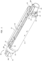
Figure 1 illustrates a shroud assembly. -
Figure 2 is a cross-sectional view of the shroud assembly ofFigure 1 . -
Figure 3 is an end view of the shroud assembly. -
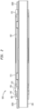
Figure 4 shows the shroud assembly assembled on the screen. -
Figure 5 illustrate another shroud assembly. -
Figure 6 is an end view of the shroud assembly. -
Figure 7 shows the shroud assembly assembled on the screen. -
Figure 8 illustrates another shroud assembly. -
Figure 9 is an enlarged partial view of the shroud assembly. -
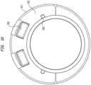
Figure 10 is an end view of the shroud assembly. -
Figure 11 is a cross-sectional view of the shroud assembly ofFigure 8 . -
Figure 12 illustrate an arrangement of nozzles on a shunt tube string. -
Figure 13 illustrate another arrangement of nozzles on a shunt tube string. - In one aspect of the present disclosure there is provided a shroud assembly as specified in
claim 1. -
Figure 1 illustrates ashroud assembly 100.Figure 2 is a cross-sectional view of theshroud assembly 100 ofFigure 1 .Figure 3 is an end view of theshroud assembly 100. Theshroud assembly 100 is used to protect ajumper tube assembly 102 forcoupling shunt tubes screen 105. Theshroud assembly 100 includes two semi-cylindrical covers 111, 112 having a first end attachable to afirst receiver ring 121 and a second end attachable to asecond receiver ring 122. The twocovers receiver rings Figure 1 , or using a dovetail connection, as shown inFigure 5 as will be described below. - As shown in
Figure 1 , eachcover more pins 125 extending out of each end. For example, threepins 125 extend out of each end of eachcover pins 125 engage arespective slot 135 formed on the exterior surface of thereceiver rings first receiver ring 121 is fixed relative to thescreen 105. Thesecond receiver ring 122 is movable relative to thescreen 105 and toward thefirst receiver ring 121. A plurality ofpins 125 are circumferentially spaced around eachcover Figure 1 , threepins 125 are disposed at each end of thecovers pins 125 are spaced sufficiently such that thecovers receiver rings covers receiver rings pins 125 are in theslots 135 of thereceiver rings - The
shroud assembly 100 also includes abase ring 140 and anextender ring 150. Thebase ring 140 is attached to thescreen 105 and includesgrooves 142 to accommodate theshunt tubes 106A. Thebase ring 140 includes abore 144 for holding thescreen 105, and bothgrooves 142 are formed less than 180 degrees apart. Thescreen bore 144 is an eccentric bore relative to a central axis of thebase ring 140. One end of theextender ring 150 is threadedly coupled to thebase ring 140, and the other end of theextender ring 150 abuts thesecond receiver ring 122. Theextender ring 150 is configured to move thesecond receiver ring 122 toward thefirst receiver ring 121. The rotation of theextender ring 150 relative to thebase ring 140 causes axial movement of thesecond receiver ring 122 away from thebase ring 140 and toward thefirst receiver ring 121. Atorque key 160 extends from aslot 146 in thebase ring 140 to a slot in thesecond receiver ring 122. Thesecond receiver ring 122 moves axially relative to thetorque key 160. - During assembly, the
pins 125 of thecovers respective slots 135 of the first andsecond receiver rings pins 125 at one end are aligned with theslots 135 of thefirst receiver ring 121 and then inserted to at least partially overlap with theslots 135 of thefirst receiver ring 121. Thereafter, theextender ring 150 is rotated relative to thebase ring 140 to urge thesecond receiver ring 122 toward the first receiver ring. During movement, thepins 125 at the other end of thecover slots 135 of thesecond receiver ring 122. Theextender ring 150 may be rotated until thepins 125 of thecovers slots 135. Thesecond receiver ring 122 is moved toward thefirst receiver ring 121 until thecovers first receiver ring 121, thereby locking thecovers Figure 4 shows theshroud assembly 100 assembled on thescreen 105. Thecovers holder openings covers covers -
Figure 5 illustrates another shroud assembly 200.Figure 6 is an end view of the shroud assembly 200.Figure 7 is a perspective of the shroud assembly 200 installed on a tubular string. The shroud assembly 200 is used to protect ajumper tube assembly 102 forcoupling shunt tubes screen 105. The shroud assembly 200 uses a dovetail connection for coupling thecovers semi-cylindrical covers first receiver ring 221 and a second end attachable to asecond receiver ring 222. Eachreceiver ring bore 227 to house thescreen 105 and includes shunt bores 228 to accommodate theshunt tubes - As shown in
Figure 5 , eachcover cover respective slot 235 formed on the exterior surface of the receiver rings 221, 222. Thefirst receiver ring 221 is fixed relative to thescreen 105. Thesecond receiver ring 222 is movable relative to thescreen 105 and toward thefirst receiver ring 221. A plurality of dovetails 225 are circumferentially spaced around eachcover Figure 5 , three dovetails 225 are disposed at each end of thecovers covers covers slots 235 of the receiver rings 221, 222 and cannot move axially out of engagement with theslots 235. Adovetail 225 is located at opposite edges of the end of thecover dovetail 225 located between them. - The shroud assembly 200 also includes a
base ring 240 and anextender ring 250. Thebase ring 240 is attached to thescreen 105 and includesgrooves 242 to accommodate theshunt tubes 106A. Thebase ring 240 includes a bore for holding thescreen 105, and bothgrooves 242 are formed less than 180 degrees apart. The screen bore is an eccentric bore relative to a central axis of thebase ring 240. One end of theextender ring 250 is threadedly coupled to thebase ring 240, and the other end of theextender ring 250 abuts thesecond receiver ring 222. Theextender ring 250 is configured to move thesecond receiver ring 222 toward thefirst receiver ring 221. The rotation of theextender ring 250 relative to thebase ring 240 causes axial movement of thesecond receiver ring 222 away from thebase ring 240 and toward thefirst receiver ring 221. Atorque key 260 extends from a slot in thebase ring 240 to a slot in thesecond receiver ring 222. Thesecond receiver ring 222 moves axially relative to thetorque key 260. - During assembly, the dovetails 225 of the
covers respective slots 235 of the first and second receiver rings 221, 222. The dovetails 225 at one end are aligned with theslots 235 of thefirst receiver ring 221 and then inserted to at least partially overlap with theslots 235 of thefirst receiver ring 221. Also, the dovetails 225 at the other end of thecover slots 235 of thesecond receiver ring 222. Thereafter, theextender ring 250 is rotated relative to thebase ring 240 to urge thesecond receiver ring 222 toward the first receiver ring. Theextender ring 250 may be rotated until the dovetails 225 of thecovers slots 235. Thesecond receiver ring 222 is moved toward thefirst receiver ring 221 until thecovers first receiver ring 221, thereby locking thecovers Figure 7 shows the shroud assembly 200 assembled on thescreen 105. Thecovers -
Figure 8 illustrates anothershroud assembly 300.Figure 9 is an enlarged partial view of theshroud assembly 300.Figure 10 is an end view of theshroud assembly 300.Figure 11 is a cross-sectional view of the receiver ring of theshroud assembly 300 ofFigure 8 . Theshroud assembly 300 is used to protect ajumper tube assembly 302 forcoupling shunt tubes 306 attached to a tubular string, such as ascreen 105. Theshroud assembly 300 includes two semi-cylindrical covers 311 (only one shown for clarity) having a first end attached to afirst receiver ring 321 and a second end attachable to asecond receiver ring 322. The receiver rings 321, 322 are made of two semi-circular halves that are pivotally coupled to each other using ahinge 323. The receiver rings 321, 322 have aninner profile 339 configured to accommodate thescreen 105 and theshunt tubes 306A, 306B. InFigure 9 , theinner profile 339 accommodating thescreen 105 and theshunt tubes 306 is contiguous. Thecovers 311, 312 are attached to aflange 324 of the receiver rings 321, 322. Theflange 324 is formed by welding a flange ring to thereceiver ring fastener 344, such as a screw, a self-retaining mechanism, a bolt, or other suitable fasteners. The flange can be machined on the receiving ring. - The
first receiver ring 321 may be positioned adjacent abase ring 318 attached to thescreen 105. One ormore torque keys 360 extend from a slot in thebase ring 318 to aslot 327 in thefirst receiver ring 322.Figure 9 shows twotorque keys 360 coupling thereceiver ring 321 to thebase ring 318. - An
intermediate receiver ring 329 may be used to extend the length of theshroud assembly 300. InFigure 8 , theintermediate receiver ring 329 has aflange 324 on both ends. Theflanges 324 allow acover 311 to be attached to each end of theintermediate receiver ring 329. - The shroud assembly described herein is suitable for protecting other downhole devices. For example, the shroud assembly can be used to protect a wire, cable, coil, electronic devices, and other downhole devices.
- The nozzles on the shunt tubes may be configured to control the pressure drop along the length of the shunt tubes. In general, the shunt tubes transport the slurry along the screen. The nozzles of the shunt tubes are used to eject the slurry out into the annular area between the screen and the wellbore. The total amount of fluid outflow at each joint or group of joints is different.
-
Figure 12 shows a shunt tube having a plurality of joints 401-405. Each joint 401-405 of the shunt tube may have a different number of nozzles 411-414. The number of nozzles increases as the shunt tube extend deeper into the wellbore. A first upper joint may have X number of nozzles, and the next joint may have one more nozzle, i.e., X+1 nozzles. The third joint down may have two more nozzles. It is contemplated that the number of nozzles on the subsequent joint may increase by more than 1, such as by, 2, 3, 4, 5, or 10 nozzles. The uppermost joint, joint 401, does not have any nozzles. The next joint, joint 402, has asingle nozzle 411.Joint 403 has twonozzles 412, and joint 404 has threenozzles 413. The lowermost joint, joint 405, has fournozzles 414. - A group of joints may have the same number of nozzles, while the next group of joints may have more or less nozzles. For example, a group of Z joints may have Y number of nozzles, and the next group of Z joints may each have 2 more or fewer nozzles. In
Figure 13 ,group 1 includesjoints nozzles 441.Group 2 includesjoints nozzles 444. - The size of the nozzles may increase as the shunt tubes extend deeper into the wellbore. The size of the nozzles may increase, while the number of nozzles remains the same as the shunt tubes extend deeper into the wellbore. The size and/or the number of nozzles may change as the shunt tubes extend deeper into the wellbore.
- The spacing of the nozzles may change as the shunt tubes extend deeper into the wellbore. For example, the spacing of nozzles may decrease as the shunt tubes extend deeper into the wellbore.
- A tubular string assembly may include a plurality of receiver rings; a tubular string disposed through the plurality of receiver rings; a shunt tube assembly supported by the plurality of receiver rings, the shunt tube assembly including a jumper tube assembly; and two semi-cylindrical covers disposed attached to the plurality of receiver rings and enclosed around the tubular string.
- The assembly may include an extender ring configured to move a first receiver ring toward a second receiver ring.
- The covers may enclose the jumper tube assembly.
- A shroud assembly includes two semi-cylindrical covers having a connector at each end; a plurality of receiver rings for supporting the covers and engaging the connector; and an extender ring configured to move a first receiver ring toward a second receiver ring.
- The assembly may include a base ring coupled to the extender ring.
- The extender ring may be rotatable relative to the base ring.
- The extender ring may be disposed between the base ring and the first receiver ring.
- The first receiver ring may be axially movable relative to the base ring.
- The assembly may include a torque key coupled to the base ring and the first receiver ring.
- The plurality of receiver rings may include a slot for engaging the connector.
- The connector may be moved axially into engagement with the slot.
- The covers may not move radially relative to the plurality of receiver rings.
- The connector may comprise a plurality of pins.
- The connector may comprise a plurality of dovetails.
- The shroud assembly may enclose a device selected from the group consisting of a shunt tube, a wire, a cable, a coil, an electronic devices, and combinations thereof.
- A shroud assembly may include a plurality of receiver rings, each ring having two portions pivotally coupled to each other; two semi-cylindrical covers attached to the plurality of receiver rings; and a fastener for locking the two portions together.
- The plurality of receiver rings may include a flange for attaching the covers.
- The flange may be formed by attaching a flange ring to the plurality of receiver rings.
- The flange may be machined onto the plurality of receiver rings.
- The plurality of receiver rings may include an inner profile for accommodating a screen and a tube.
- The assembly may include a base ring rotationally fixed relative to the plurality of receiver rings.
- A shunt tube assembly may include a plurality of joints of shunt tube, each of the joints include at least one nozzle, wherein a first joint located adjacent to a second joint has a different fluid outflow than the second joint.
- The first joint and the second joint may have a different number of nozzles.
- Three adjacent joints may have a different number of nozzles.
- The number of nozzles may increase with respect to the joints in descending order.
- A third joint located adjacent to the second joint may have the same number of nozzles as the second joint.
- A size of a nozzle of the first joint may be different from a size of a nozzle of the second joint.
- The scope of the present invention is determined by the claims that follow.
Claims (12)
- A shroud assembly (100), comprising:two semi-cylindrical covers (111, 112) having a connector at each end;a plurality of receiver rings (121, 122) for supporting the covers and engaging the connector; and characterised in that the shroud assembly further comprisesan extender ring (150) configured to move a first receiver ring toward a second receiver ring.
- The assembly of claim 1, further comprising a base ring (140) coupled to the extender ring.
- The assembly of claim 2, wherein the extender ring is rotatable relative to the base ring.
- The assembly of claim 3, wherein the extender ring is disposed between the base ring and the first receiver ring.
- The assembly of claims 2, 3 or 4, wherein the first receiver ring is axially movable relative to the base ring.
- The assembly of any of claims 2 to 5, further comprising a torque key (160) coupled to the base ring and the first receiver ring.
- The assembly of any preceding claim, wherein the plurality of receiver rings include a slot (135) for engaging the connector.
- The assembly of claim 7, wherein the connector is moved axially into engagement with the slot (135).
- The assembly of claim 7 or 8, wherein the covers cannot move radially relative to the plurality of receiver rings.
- The assembly of any preceding claim, wherein the connector comprises a plurality of pins (125).
- The assembly of any one of claims 1 to 9, wherein the connector comprises a plurality of dovetails (225).
- The assembly of any preceding claim, wherein the shroud assembly encloses a device selected from the group consisting of a shunt tube, a wire, a cable, a coil, an electronic device, and combinations thereof.
Priority Applications (1)
| Application Number | Priority Date | Filing Date | Title |
|---|---|---|---|
| EP23184359.0A EP4253716B1 (en) | 2017-04-12 | 2018-04-12 | Shroud assembly |
Applications Claiming Priority (2)
| Application Number | Priority Date | Filing Date | Title |
|---|---|---|---|
| US201762484884P | 2017-04-12 | 2017-04-12 | |
| PCT/US2018/027235 WO2018191455A1 (en) | 2017-04-12 | 2018-04-12 | Shroud assembly |
Related Child Applications (2)
| Application Number | Title | Priority Date | Filing Date |
|---|---|---|---|
| EP23184359.0A Division-Into EP4253716B1 (en) | 2017-04-12 | 2018-04-12 | Shroud assembly |
| EP23184359.0A Division EP4253716B1 (en) | 2017-04-12 | 2018-04-12 | Shroud assembly |
Publications (2)
| Publication Number | Publication Date |
|---|---|
| EP3610126A1 EP3610126A1 (en) | 2020-02-19 |
| EP3610126B1 true EP3610126B1 (en) | 2025-03-12 |
Family
ID=62063664
Family Applications (2)
| Application Number | Title | Priority Date | Filing Date |
|---|---|---|---|
| EP23184359.0A Active EP4253716B1 (en) | 2017-04-12 | 2018-04-12 | Shroud assembly |
| EP18720753.5A Active EP3610126B1 (en) | 2017-04-12 | 2018-04-12 | Shroud assembly |
Family Applications Before (1)
| Application Number | Title | Priority Date | Filing Date |
|---|---|---|---|
| EP23184359.0A Active EP4253716B1 (en) | 2017-04-12 | 2018-04-12 | Shroud assembly |
Country Status (6)
| Country | Link |
|---|---|
| US (1) | US10920537B2 (en) |
| EP (2) | EP4253716B1 (en) |
| AU (1) | AU2018251878B2 (en) |
| CA (2) | CA3059361C (en) |
| EA (1) | EA201992412A1 (en) |
| WO (1) | WO2018191455A1 (en) |
Families Citing this family (2)
| Publication number | Priority date | Publication date | Assignee | Title |
|---|---|---|---|---|
| US10767793B2 (en) * | 2017-03-14 | 2020-09-08 | Delta Screen & Filtration, Llc | Jumper tube connector |
| US12264560B2 (en) | 2021-05-04 | 2025-04-01 | Schlumberger Technology Corporation | Torque resistant shroud system |
Citations (3)
| Publication number | Priority date | Publication date | Assignee | Title |
|---|---|---|---|---|
| US5540465A (en) * | 1994-08-01 | 1996-07-30 | Sisk; David E. | Pipe, valve and/or tee coupler |
| WO1997017567A1 (en) * | 1995-11-04 | 1997-05-15 | Nicc Limited | Coating of pipe joints |
| US5895076A (en) * | 1996-11-04 | 1999-04-20 | Tyler J. Elliot | Hose coupling shroud |
Family Cites Families (24)
| Publication number | Priority date | Publication date | Assignee | Title |
|---|---|---|---|---|
| US5390966A (en) | 1993-10-22 | 1995-02-21 | Mobil Oil Corporation | Single connector for shunt conduits on well tool |
| US6409219B1 (en) | 1999-11-12 | 2002-06-25 | Baker Hughes Incorporated | Downhole screen with tubular bypass |
| US7866708B2 (en) | 2004-03-09 | 2011-01-11 | Schlumberger Technology Corporation | Joining tubular members |
| CA2669007C (en) | 2006-11-15 | 2012-12-04 | Exxonmobil Upstream Research Company | Wellbore method and apparatus for completion, production and injection |
| US7828056B2 (en) | 2007-07-06 | 2010-11-09 | Schlumberger Technology Corporation | Method and apparatus for connecting shunt tubes to sand screen assemblies |
| WO2010047708A1 (en) * | 2008-10-23 | 2010-04-29 | Baker Hughes Incorporated | Equalizing injection tool |
| GB2488290B (en) * | 2008-11-11 | 2013-04-17 | Swelltec Ltd | Wellbore apparatus and method |
| US8783348B2 (en) | 2010-12-29 | 2014-07-22 | Baker Hughes Incorporated | Secondary flow path module, gravel packing system including the same, and method of assembly thereof |
| US8789611B2 (en) | 2012-02-29 | 2014-07-29 | Halliburton Energy Services, Inc. | Rotating and translating shunt tube assembly |
| WO2013187876A1 (en) | 2012-06-11 | 2013-12-19 | Halliburton Energy Services, Inc. | Jumper tube locking assembly and method |
| WO2013187877A1 (en) | 2012-06-11 | 2013-12-19 | Halliburton Energy Services, Inc. | Shunt tube connection and distribution assembly and method |
| EP3460174B1 (en) | 2012-06-11 | 2020-04-22 | Halliburton Energy Services Inc. | Shunt tube connection assembly and method |
| MY191667A (en) | 2012-10-18 | 2022-07-06 | Halliburton Energy Services Inc | Gravel packing apparatus having a jumper tube protection assembly |
| US8807205B2 (en) | 2012-10-19 | 2014-08-19 | Halliburton Energy Services, Inc. | Gravel packing apparatus having a rotatable slurry delivery subassembly |
| US9394765B2 (en) | 2012-12-07 | 2016-07-19 | Halliburton Energy Services, Inc. | Gravel packing apparatus having locking jumper tubes |
| WO2014120167A1 (en) | 2013-01-31 | 2014-08-07 | Halliburton Energy Systems, Inc. | Spring clips for tubular connection |
| WO2014133553A1 (en) | 2013-03-01 | 2014-09-04 | Halliburton Energy Services, Inc. | Misalignment in coupling shunt tubes of well screen assemblies |
| US8931568B2 (en) | 2013-03-14 | 2015-01-13 | Weatherford/Lamb, Inc. | Shunt tube connections for wellscreen assembly |
| US9580999B2 (en) | 2013-05-20 | 2017-02-28 | Halliburton Energy Services, Inc. | Gravel packing apparatus having a jumper tube protection assembly |
| US10215018B2 (en) * | 2014-01-07 | 2019-02-26 | Schlumberger Technology Corporation | Fluid tracer installation |
| CA2937378C (en) * | 2014-02-24 | 2017-01-03 | Delta Screen & Filtration, Llc | Shunt tube connector assembly and method |
| BR112017016450B1 (en) * | 2015-03-06 | 2022-06-14 | Halliburton Energy Services, Inc | SET AND APPARATUS ADAPTED TO BE DISPOSED INSIDE A WELL, AND METHOD FOR CONSTITUTING A CONNECTION BETWEEN A FIRST AND SECOND COMPLETION JOINTS |
| US10480293B2 (en) | 2015-08-31 | 2019-11-19 | Schlumberger Technology Corporation | Tubing system having alternate path |
| US11131152B2 (en) * | 2016-03-28 | 2021-09-28 | Halliburton Energy Services, Inc. | Self-locking coupler |
-
2018
- 2018-04-12 US US15/951,923 patent/US10920537B2/en active Active
- 2018-04-12 EP EP23184359.0A patent/EP4253716B1/en active Active
- 2018-04-12 WO PCT/US2018/027235 patent/WO2018191455A1/en not_active Ceased
- 2018-04-12 EA EA201992412A patent/EA201992412A1/en unknown
- 2018-04-12 CA CA3059361A patent/CA3059361C/en active Active
- 2018-04-12 AU AU2018251878A patent/AU2018251878B2/en active Active
- 2018-04-12 CA CA3190990A patent/CA3190990C/en active Active
- 2018-04-12 EP EP18720753.5A patent/EP3610126B1/en active Active
Patent Citations (3)
| Publication number | Priority date | Publication date | Assignee | Title |
|---|---|---|---|---|
| US5540465A (en) * | 1994-08-01 | 1996-07-30 | Sisk; David E. | Pipe, valve and/or tee coupler |
| WO1997017567A1 (en) * | 1995-11-04 | 1997-05-15 | Nicc Limited | Coating of pipe joints |
| US5895076A (en) * | 1996-11-04 | 1999-04-20 | Tyler J. Elliot | Hose coupling shroud |
Also Published As
| Publication number | Publication date |
|---|---|
| CA3190990A1 (en) | 2018-10-18 |
| EP4253716B1 (en) | 2025-05-14 |
| CA3059361A1 (en) | 2018-10-18 |
| CA3059361C (en) | 2024-01-02 |
| AU2018251878B2 (en) | 2022-12-08 |
| CA3190990C (en) | 2025-05-27 |
| BR112019021457A2 (en) | 2020-05-05 |
| WO2018191455A1 (en) | 2018-10-18 |
| EP4253716A3 (en) | 2023-12-06 |
| US10920537B2 (en) | 2021-02-16 |
| EP4253716A2 (en) | 2023-10-04 |
| EP3610126A1 (en) | 2020-02-19 |
| EA201992412A1 (en) | 2020-03-31 |
| US20180298730A1 (en) | 2018-10-18 |
| AU2018251878A1 (en) | 2019-12-05 |
Similar Documents
| Publication | Publication Date | Title |
|---|---|---|
| US7828056B2 (en) | Method and apparatus for connecting shunt tubes to sand screen assemblies | |
| US6789624B2 (en) | Apparatus and method for gravel packing an interval of a wellbore | |
| US7661476B2 (en) | Gravel packing methods | |
| US9988882B2 (en) | Gravel packing apparatus having locking jumper tubes | |
| US10480293B2 (en) | Tubing system having alternate path | |
| US20140110132A1 (en) | Gravel Packing Apparatus having a Rotatable Slurry Delivery Subassembly | |
| EP4253716B1 (en) | Shroud assembly | |
| US9752417B2 (en) | Gravel packing apparatus having optimized fluid handling | |
| AU2016216652B2 (en) | Gravel Packing Apparatus Having Locking Jumper Tubes | |
| EP3051058B1 (en) | Jumper connection for shunt tubes on wellscreen assembly, method of communicating using said jumper connection and wellscreen assembly comprising said jumper connection | |
| AU2016213868B2 (en) | Gravel packing apparatus having a rotatable slurry delivery subassembly | |
| US20030188865A1 (en) | Method for assembly of a gravel packing apparatus having expandable channels | |
| GB2567351B (en) | Gravel packing apparatus having locking jumper tubes | |
| NO347727B1 (en) | Gravel packing apparatus having optimized fluid handling |
Legal Events
| Date | Code | Title | Description |
|---|---|---|---|
| STAA | Information on the status of an ep patent application or granted ep patent |
Free format text: STATUS: UNKNOWN |
|
| STAA | Information on the status of an ep patent application or granted ep patent |
Free format text: STATUS: THE INTERNATIONAL PUBLICATION HAS BEEN MADE |
|
| PUAI | Public reference made under article 153(3) epc to a published international application that has entered the european phase |
Free format text: ORIGINAL CODE: 0009012 |
|
| STAA | Information on the status of an ep patent application or granted ep patent |
Free format text: STATUS: REQUEST FOR EXAMINATION WAS MADE |
|
| 17P | Request for examination filed |
Effective date: 20191029 |
|
| AK | Designated contracting states |
Kind code of ref document: A1 Designated state(s): AL AT BE BG CH CY CZ DE DK EE ES FI FR GB GR HR HU IE IS IT LI LT LU LV MC MK MT NL NO PL PT RO RS SE SI SK SM TR |
|
| AX | Request for extension of the european patent |
Extension state: BA ME |
|
| DAV | Request for validation of the european patent (deleted) | ||
| DAX | Request for extension of the european patent (deleted) | ||
| 111Z | Information provided on other rights and legal means of execution |
Free format text: AL AT BE BG CH CY CZ DE DK EE ES FI FR GB GR HR HU IE IS IT LT LU LV MC MK MT NL NO PL PT RO RS SE SI SK SM TR AL AT BE BG CH CY CZ DE DK EE ES FI FR GB GR HR HU IE IS IT LT LU LV MC MK MT NL NO PL PT RO RS SE SI SK SM TR Effective date: 20200511 |
|
| R11X | Information provided on other rights and legal means of execution (corrected) |
Free format text: AL AT BE BG CH CY CZ DE DK EE ES FI FR GB GR HR HU IE IS IT LT LU LV MC MK MT NL NO PL PT RO RS SE SI SK SM TR Effective date: 20200511 |
|
| 111Z | Information provided on other rights and legal means of execution |
Free format text: AL AT BE BG CH CY CZ DE DK EE ES FI FR GB GR HR HU IE IS IT LT LU LV MC MK MT NL NO PL PT RO RS SE SI SK SM TR AL AT BE BG CH CY CZ DE DK EE ES FI FR GB GR HR HU IE IS IT LT LU LV MC MK MT NL NO PL PT RO RS SE SI SK SM TR Effective date: 20200511 |
|
| PUAG | Search results despatched under rule 164(2) epc together with communication from examining division |
Free format text: ORIGINAL CODE: 0009017 |
|
| STAA | Information on the status of an ep patent application or granted ep patent |
Free format text: STATUS: EXAMINATION IS IN PROGRESS |
|
| 17Q | First examination report despatched |
Effective date: 20230201 |
|
| B565 | Issuance of search results under rule 164(2) epc |
Effective date: 20230201 |
|
| RIC1 | Information provided on ipc code assigned before grant |
Ipc: E21B 17/18 20060101ALI20230130BHEP Ipc: E21B 17/046 20060101ALI20230130BHEP Ipc: E21B 43/04 20060101AFI20230130BHEP |
|
| P01 | Opt-out of the competence of the unified patent court (upc) registered |
Effective date: 20230922 |
|
| GRAP | Despatch of communication of intention to grant a patent |
Free format text: ORIGINAL CODE: EPIDOSNIGR1 |
|
| STAA | Information on the status of an ep patent application or granted ep patent |
Free format text: STATUS: GRANT OF PATENT IS INTENDED |
|
| INTG | Intention to grant announced |
Effective date: 20241007 |
|
| GRAS | Grant fee paid |
Free format text: ORIGINAL CODE: EPIDOSNIGR3 |
|
| GRAA | (expected) grant |
Free format text: ORIGINAL CODE: 0009210 |
|
| STAA | Information on the status of an ep patent application or granted ep patent |
Free format text: STATUS: THE PATENT HAS BEEN GRANTED |
|
| AK | Designated contracting states |
Kind code of ref document: B1 Designated state(s): AL AT BE BG CH CY CZ DE DK EE ES FI FR GB GR HR HU IE IS IT LI LT LU LV MC MK MT NL NO PL PT RO RS SE SI SK SM TR |
|
| REG | Reference to a national code |
Ref country code: GB Ref legal event code: FG4D |
|
| REG | Reference to a national code |
Ref country code: CH Ref legal event code: EP |
|
| REG | Reference to a national code |
Ref country code: DE Ref legal event code: R096 Ref document number: 602018080027 Country of ref document: DE |
|
| REG | Reference to a national code |
Ref country code: IE Ref legal event code: FG4D |
|
| PGFP | Annual fee paid to national office [announced via postgrant information from national office to epo] |
Ref country code: NL Payment date: 20250326 Year of fee payment: 8 |
|
| REG | Reference to a national code |
Ref country code: NL Ref legal event code: FP |
|
| PG25 | Lapsed in a contracting state [announced via postgrant information from national office to epo] |
Ref country code: RS Free format text: LAPSE BECAUSE OF FAILURE TO SUBMIT A TRANSLATION OF THE DESCRIPTION OR TO PAY THE FEE WITHIN THE PRESCRIBED TIME-LIMIT Effective date: 20250612 |
|
| PG25 | Lapsed in a contracting state [announced via postgrant information from national office to epo] |
Ref country code: FI Free format text: LAPSE BECAUSE OF FAILURE TO SUBMIT A TRANSLATION OF THE DESCRIPTION OR TO PAY THE FEE WITHIN THE PRESCRIBED TIME-LIMIT Effective date: 20250312 |
|
| PGFP | Annual fee paid to national office [announced via postgrant information from national office to epo] |
Ref country code: DE Payment date: 20250311 Year of fee payment: 8 |
|
| PG25 | Lapsed in a contracting state [announced via postgrant information from national office to epo] |
Ref country code: ES Free format text: LAPSE BECAUSE OF FAILURE TO SUBMIT A TRANSLATION OF THE DESCRIPTION OR TO PAY THE FEE WITHIN THE PRESCRIBED TIME-LIMIT Effective date: 20250312 |
|
| REG | Reference to a national code |
Ref country code: LT Ref legal event code: MG9D |
|
| PGFP | Annual fee paid to national office [announced via postgrant information from national office to epo] |
Ref country code: NO Payment date: 20250409 Year of fee payment: 8 |
|
| PG25 | Lapsed in a contracting state [announced via postgrant information from national office to epo] |
Ref country code: HR Free format text: LAPSE BECAUSE OF FAILURE TO SUBMIT A TRANSLATION OF THE DESCRIPTION OR TO PAY THE FEE WITHIN THE PRESCRIBED TIME-LIMIT Effective date: 20250312 |
|
| PG25 | Lapsed in a contracting state [announced via postgrant information from national office to epo] |
Ref country code: LV Free format text: LAPSE BECAUSE OF FAILURE TO SUBMIT A TRANSLATION OF THE DESCRIPTION OR TO PAY THE FEE WITHIN THE PRESCRIBED TIME-LIMIT Effective date: 20250312 |
|
| PG25 | Lapsed in a contracting state [announced via postgrant information from national office to epo] |
Ref country code: GR Free format text: LAPSE BECAUSE OF FAILURE TO SUBMIT A TRANSLATION OF THE DESCRIPTION OR TO PAY THE FEE WITHIN THE PRESCRIBED TIME-LIMIT Effective date: 20250613 Ref country code: BG Free format text: LAPSE BECAUSE OF FAILURE TO SUBMIT A TRANSLATION OF THE DESCRIPTION OR TO PAY THE FEE WITHIN THE PRESCRIBED TIME-LIMIT Effective date: 20250312 |
|
| REG | Reference to a national code |
Ref country code: AT Ref legal event code: MK05 Ref document number: 1775138 Country of ref document: AT Kind code of ref document: T Effective date: 20250312 |
|
| PG25 | Lapsed in a contracting state [announced via postgrant information from national office to epo] |
Ref country code: SE Free format text: LAPSE BECAUSE OF FAILURE TO SUBMIT A TRANSLATION OF THE DESCRIPTION OR TO PAY THE FEE WITHIN THE PRESCRIBED TIME-LIMIT Effective date: 20250312 |
|
| PG25 | Lapsed in a contracting state [announced via postgrant information from national office to epo] |
Ref country code: SM Free format text: LAPSE BECAUSE OF FAILURE TO SUBMIT A TRANSLATION OF THE DESCRIPTION OR TO PAY THE FEE WITHIN THE PRESCRIBED TIME-LIMIT Effective date: 20250312 |
|
| PG25 | Lapsed in a contracting state [announced via postgrant information from national office to epo] |
Ref country code: PT Free format text: LAPSE BECAUSE OF FAILURE TO SUBMIT A TRANSLATION OF THE DESCRIPTION OR TO PAY THE FEE WITHIN THE PRESCRIBED TIME-LIMIT Effective date: 20250714 |
|
| PG25 | Lapsed in a contracting state [announced via postgrant information from national office to epo] |
Ref country code: PL Free format text: LAPSE BECAUSE OF FAILURE TO SUBMIT A TRANSLATION OF THE DESCRIPTION OR TO PAY THE FEE WITHIN THE PRESCRIBED TIME-LIMIT Effective date: 20250312 Ref country code: IT Free format text: LAPSE BECAUSE OF FAILURE TO SUBMIT A TRANSLATION OF THE DESCRIPTION OR TO PAY THE FEE WITHIN THE PRESCRIBED TIME-LIMIT Effective date: 20250312 |
|
| PG25 | Lapsed in a contracting state [announced via postgrant information from national office to epo] |
Ref country code: AT Free format text: LAPSE BECAUSE OF FAILURE TO SUBMIT A TRANSLATION OF THE DESCRIPTION OR TO PAY THE FEE WITHIN THE PRESCRIBED TIME-LIMIT Effective date: 20250312 |
|
| PG25 | Lapsed in a contracting state [announced via postgrant information from national office to epo] |
Ref country code: CZ Free format text: LAPSE BECAUSE OF FAILURE TO SUBMIT A TRANSLATION OF THE DESCRIPTION OR TO PAY THE FEE WITHIN THE PRESCRIBED TIME-LIMIT Effective date: 20250312 Ref country code: EE Free format text: LAPSE BECAUSE OF FAILURE TO SUBMIT A TRANSLATION OF THE DESCRIPTION OR TO PAY THE FEE WITHIN THE PRESCRIBED TIME-LIMIT Effective date: 20250312 |
|
| PG25 | Lapsed in a contracting state [announced via postgrant information from national office to epo] |
Ref country code: RO Free format text: LAPSE BECAUSE OF FAILURE TO SUBMIT A TRANSLATION OF THE DESCRIPTION OR TO PAY THE FEE WITHIN THE PRESCRIBED TIME-LIMIT Effective date: 20250312 |
|
| PG25 | Lapsed in a contracting state [announced via postgrant information from national office to epo] |
Ref country code: SK Free format text: LAPSE BECAUSE OF FAILURE TO SUBMIT A TRANSLATION OF THE DESCRIPTION OR TO PAY THE FEE WITHIN THE PRESCRIBED TIME-LIMIT Effective date: 20250312 |
|
| PG25 | Lapsed in a contracting state [announced via postgrant information from national office to epo] |
Ref country code: IS Free format text: LAPSE BECAUSE OF FAILURE TO SUBMIT A TRANSLATION OF THE DESCRIPTION OR TO PAY THE FEE WITHIN THE PRESCRIBED TIME-LIMIT Effective date: 20250712 |
|
| REG | Reference to a national code |
Ref country code: CH Ref legal event code: H13 Free format text: ST27 STATUS EVENT CODE: U-0-0-H10-H13 (AS PROVIDED BY THE NATIONAL OFFICE) Effective date: 20251125 |
|
| PG25 | Lapsed in a contracting state [announced via postgrant information from national office to epo] |
Ref country code: LU Free format text: LAPSE BECAUSE OF NON-PAYMENT OF DUE FEES Effective date: 20250412 |
|
| REG | Reference to a national code |
Ref country code: DE Ref legal event code: R097 Ref document number: 602018080027 Country of ref document: DE |
|
| PG25 | Lapsed in a contracting state [announced via postgrant information from national office to epo] |
Ref country code: MC Free format text: LAPSE BECAUSE OF FAILURE TO SUBMIT A TRANSLATION OF THE DESCRIPTION OR TO PAY THE FEE WITHIN THE PRESCRIBED TIME-LIMIT Effective date: 20250312 |
|
| REG | Reference to a national code |
Ref country code: BE Ref legal event code: MM Effective date: 20250430 |
|
| PG25 | Lapsed in a contracting state [announced via postgrant information from national office to epo] |
Ref country code: DK Free format text: LAPSE BECAUSE OF FAILURE TO SUBMIT A TRANSLATION OF THE DESCRIPTION OR TO PAY THE FEE WITHIN THE PRESCRIBED TIME-LIMIT Effective date: 20250312 |
|
| PG25 | Lapsed in a contracting state [announced via postgrant information from national office to epo] |
Ref country code: BE Free format text: LAPSE BECAUSE OF NON-PAYMENT OF DUE FEES Effective date: 20250430 |
|
| PLBE | No opposition filed within time limit |
Free format text: ORIGINAL CODE: 0009261 |
|
| STAA | Information on the status of an ep patent application or granted ep patent |
Free format text: STATUS: NO OPPOSITION FILED WITHIN TIME LIMIT |
|
| PG25 | Lapsed in a contracting state [announced via postgrant information from national office to epo] |
Ref country code: CH Free format text: LAPSE BECAUSE OF NON-PAYMENT OF DUE FEES Effective date: 20250430 |
|
| REG | Reference to a national code |
Ref country code: CH Ref legal event code: L10 Free format text: ST27 STATUS EVENT CODE: U-0-0-L10-L00 (AS PROVIDED BY THE NATIONAL OFFICE) Effective date: 20260121 |
|
| 26N | No opposition filed |
Effective date: 20251215 |
|
| PGFP | Annual fee paid to national office [announced via postgrant information from national office to epo] |
Ref country code: GB Payment date: 20260310 Year of fee payment: 9 |
|
| PG25 | Lapsed in a contracting state [announced via postgrant information from national office to epo] |
Ref country code: IE Free format text: LAPSE BECAUSE OF NON-PAYMENT OF DUE FEES Effective date: 20250412 |
|
| PG25 | Lapsed in a contracting state [announced via postgrant information from national office to epo] |
Ref country code: FR Free format text: LAPSE BECAUSE OF NON-PAYMENT OF DUE FEES Effective date: 20250512 |