EP3609827B1 - Pipe tensioner - Google Patents
Pipe tensioner Download PDFInfo
- Publication number
- EP3609827B1 EP3609827B1 EP17804938.3A EP17804938A EP3609827B1 EP 3609827 B1 EP3609827 B1 EP 3609827B1 EP 17804938 A EP17804938 A EP 17804938A EP 3609827 B1 EP3609827 B1 EP 3609827B1
- Authority
- EP
- European Patent Office
- Prior art keywords
- load
- pipeline
- pad
- loading
- tensioner
- Prior art date
- Legal status (The legal status is an assumption and is not a legal conclusion. Google has not performed a legal analysis and makes no representation as to the accuracy of the status listed.)
- Active
Links
Images




Classifications
-
- F—MECHANICAL ENGINEERING; LIGHTING; HEATING; WEAPONS; BLASTING
- F16—ENGINEERING ELEMENTS AND UNITS; GENERAL MEASURES FOR PRODUCING AND MAINTAINING EFFECTIVE FUNCTIONING OF MACHINES OR INSTALLATIONS; THERMAL INSULATION IN GENERAL
- F16L—PIPES; JOINTS OR FITTINGS FOR PIPES; SUPPORTS FOR PIPES, CABLES OR PROTECTIVE TUBING; MEANS FOR THERMAL INSULATION IN GENERAL
- F16L1/00—Laying or reclaiming pipes; Repairing or joining pipes on or under water
- F16L1/12—Laying or reclaiming pipes on or under water
- F16L1/20—Accessories therefor, e.g. floats or weights
- F16L1/23—Pipe tensioning apparatus
-
- B—PERFORMING OPERATIONS; TRANSPORTING
- B65—CONVEYING; PACKING; STORING; HANDLING THIN OR FILAMENTARY MATERIAL
- B65H—HANDLING THIN OR FILAMENTARY MATERIAL, e.g. SHEETS, WEBS, CABLES
- B65H51/00—Forwarding filamentary material
- B65H51/14—Aprons, endless belts, lattices, or like driven elements
-
- F—MECHANICAL ENGINEERING; LIGHTING; HEATING; WEAPONS; BLASTING
- F16—ENGINEERING ELEMENTS AND UNITS; GENERAL MEASURES FOR PRODUCING AND MAINTAINING EFFECTIVE FUNCTIONING OF MACHINES OR INSTALLATIONS; THERMAL INSULATION IN GENERAL
- F16L—PIPES; JOINTS OR FITTINGS FOR PIPES; SUPPORTS FOR PIPES, CABLES OR PROTECTIVE TUBING; MEANS FOR THERMAL INSULATION IN GENERAL
- F16L1/00—Laying or reclaiming pipes; Repairing or joining pipes on or under water
- F16L1/12—Laying or reclaiming pipes on or under water
- F16L1/20—Accessories therefor, e.g. floats or weights
- F16L1/202—Accessories therefor, e.g. floats or weights fixed on or to vessels
- F16L1/207—Pipe handling apparatus
-
- F—MECHANICAL ENGINEERING; LIGHTING; HEATING; WEAPONS; BLASTING
- F16—ENGINEERING ELEMENTS AND UNITS; GENERAL MEASURES FOR PRODUCING AND MAINTAINING EFFECTIVE FUNCTIONING OF MACHINES OR INSTALLATIONS; THERMAL INSULATION IN GENERAL
- F16L—PIPES; JOINTS OR FITTINGS FOR PIPES; SUPPORTS FOR PIPES, CABLES OR PROTECTIVE TUBING; MEANS FOR THERMAL INSULATION IN GENERAL
- F16L1/00—Laying or reclaiming pipes; Repairing or joining pipes on or under water
- F16L1/12—Laying or reclaiming pipes on or under water
- F16L1/20—Accessories therefor, e.g. floats or weights
- F16L1/235—Apparatus for controlling the pipe during laying
-
- G—PHYSICS
- G01—MEASURING; TESTING
- G01L—MEASURING FORCE, STRESS, TORQUE, WORK, MECHANICAL POWER, MECHANICAL EFFICIENCY, OR FLUID PRESSURE
- G01L5/00—Apparatus for, or methods of, measuring force, work, mechanical power, or torque, specially adapted for specific purposes
- G01L5/04—Apparatus for, or methods of, measuring force, work, mechanical power, or torque, specially adapted for specific purposes for measuring tension in flexible members, e.g. ropes, cables, wires, threads, belts or bands
- G01L5/10—Apparatus for, or methods of, measuring force, work, mechanical power, or torque, specially adapted for specific purposes for measuring tension in flexible members, e.g. ropes, cables, wires, threads, belts or bands using electrical means
- G01L5/101—Apparatus for, or methods of, measuring force, work, mechanical power, or torque, specially adapted for specific purposes for measuring tension in flexible members, e.g. ropes, cables, wires, threads, belts or bands using electrical means using sensors inserted into the flexible member
-
- G—PHYSICS
- G01—MEASURING; TESTING
- G01L—MEASURING FORCE, STRESS, TORQUE, WORK, MECHANICAL POWER, MECHANICAL EFFICIENCY, OR FLUID PRESSURE
- G01L5/00—Apparatus for, or methods of, measuring force, work, mechanical power, or torque, specially adapted for specific purposes
- G01L5/16—Apparatus for, or methods of, measuring force, work, mechanical power, or torque, specially adapted for specific purposes for measuring several components of force
- G01L5/161—Apparatus for, or methods of, measuring force, work, mechanical power, or torque, specially adapted for specific purposes for measuring several components of force using variations in ohmic resistance
- G01L5/1627—Apparatus for, or methods of, measuring force, work, mechanical power, or torque, specially adapted for specific purposes for measuring several components of force using variations in ohmic resistance of strain gauges
Definitions
- Subsea marine pipelines are well known in the art for transporting fluids, for example hydrocarbons such as oil and gas.
- Such pipelines can be laid on a seabed or a sea floor for the passage of fluids between two sites, such as a production well or well head and an adjacent production platform.
- Such pipelines also need to be recovered from a sea bed after use.
- a first method consists of constructing the pipeline on a vertical assembly line and laying it in a vertical position. This method is particularly suitable for laying underwater pipelines in very deep water (generally, a depth greater than 1500m).
- S Lay the pipeline is laid in a horizontal configuration.
- Subsea pipelines are generally laid from a pipe-laying vessel, sometimes termed a marine pipelay vessel.
- a third method may be employed in which the pipeline can be formed 'onshore' and located on a large storage drum or reel on the pipe-laying vessel for subsequent laying 'off-shore' directly from the reel.
- This is generally termed in the art ⁇ reel-laying'.
- the pipeline needs to be reeled or spooled both onto and later off from the reel, based on controlled movement, which can be provided by a suitable tensioning assembly.
- the pipe-laying vessel usually has a marine pipelay assembly thereon, such as a tower, for organising the pipeline from the vessel into the sea.
- the marine pipelay assembly may control the direction, speed and/or other parameters of the pipeline during its laying operation, and the movement between the pipeline and vessel is generally controlled by one or more apparatus or devices intended to grip and/or apply tension to the pipeline during its passage through the marine pipelay assembly. Suitable devices or apparatus for this purpose are known as "tensioners".
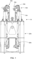
- the tensioner (1A) comprises multiple continuous tracks (10A) which are adapted to engage the pipeline and support at least the weight of the pipeline.
- the tracks (10A) are each supported by a chassis (13A) which is mounted on a support structure (20A) by cylinders (26A).
- the cylinders (26A) provide relative movement of the tracks (10A) in order to provide clamping force from the tracks (10A) onto the pipeline. This allows the pipeline to be held in place by friction between the tracks (10A) and the external surface of the pipeline.
- Each track (10A) comprises multiple pipe tensioner pads (16A) on its external, pipe contacting, surface.
- the friction is provided by the external, i.e. pipe contacting, surface of each pad, being formed from steel with a roughened surface or ridges or from a material having a relatively high coefficient of friction such as rubber or polyurethane.
- This pipe contacting surface and in particular in the case of non-steel pipe contacting surface, is bonded to a rigid back plate, or support, in order to provide the pipe tensioner pad with the required mechanical strength.
- This back plate is conventionally made of steel.
- the clamping force applied by the tensioner on the pipeline is a key parameter in pipe laying.
- An excessive clamping force may damage the pipeline.
- insufficient clamping force may lead to an unsuitable or unstable grip of the pipeline, and moving the pipeline in an uncontrolled manner may damage the pipeline and affect security of nearby users or operators.
- the field joint coated section is typically thicker than the other parts of the pipeline, which will create a change in the necessary clamping force which the operator needs to take account of as the pipeline diameter varies during pipeline laying.
- axial and side loads cannot be measured with such methodology, but such values would provide beneficial guidance on the behaviour of the pad, and thus on the efficiency of the handling of the pipeline by the tensioner.
- WO 93/06401A also shows a pipelay stringer useful in understanding the background to the present invention.
- a pipe tensioner for laying or recovering a subsea pipeline as defined in claim 1.
- a marine pipelay assembly comprising a pipe tensioner as defined herein.
- the present invention provides a pipe tensioner comprising at least two opposing continuous tracks for handling a subsea pipeline, typically being either laying the subsea pipeline from a vessel, or recovering the subsea pipeline onto a vessel, and typically in, on or through a marine pipelay assembly, wherein at least one pad on one of the tracks of the pipe tensioner is a load pad comprising one or more load sensors for measuring loading on the load pad during handling of the subsea pipeline.
- the term "laying” encompasses all the operations involved in the laying of the subsea pipeline including, but not limited to, spooling and/or unspooling a subsea pipeline on or from a reel located on a pipe-laying vessel.
- a pipe tensioner typically has 2, 3 or 4 opposing continuous tracks, generally in a symmetrical arrangement around a pipeline pathway therethrough.
- the pipe tensioner is supported by or within a tower, sometimes termed a pipelay tower, which can be part of the marine pipelay assembly.
- a tower provides the direction or ⁇ firing line' for the subsea pipeline, especially during laying.
- the pipe tensioner It is an expected function of the pipe tensioner to handle the subsea pipeline during laying or recovering with expected amount of control, including at an appropriate speed.
- this includes being to be able to hold or pause any pipeline movement when it is desired to carry out one or more other actions during pipeline laying or recovering, such as adding an intermediate unit, device or apparatus into the pipeline, joining pipeline sections or stalks, or conducting known subsea operations on a pipeline.
- the pipe tensioner is expected to be able to provide the correct amount of tension in the form of the clamping force at all times.
- the overall clamping force from the tracks onto the pipeline is provided by cylinders between a tensioner support structure and a chassis for each track, and is distributed between the pads of each tensioner track in contact with the subsea pipeline during laying or recovering of the subsea pipeline.
- the distribution of the overall clamping force may be uniform or heterogeneous between each of such pads. This overall distributed clamping force is considered to be the loading between the subsea pipeline and the pipe tensioner.
- the pad During the handling and passage of a pipeline through a pipe tensioner, the pad withstands one or more of three main forms of loading, being axial loading (Fx), normal loading (Fz), and side loading (Fy).
- the axial loading (Fx) is the component of the loading parallel to the longitudinal axis of the pipeline.
- the normal loading (Fz) is the component of the loading oriented along the radius of the pipeline joining the centre of the pipe contacting surface of the pad.
- the side loading (Fy) is the component of the loading orthogonal to the axial loading and normal loading.
- Normal loading on each pad of the continuous tracks can be up to 425 kN, generally between 50 kN and 368 kN; axial loading on each pad of the continuous tracks can be up to 85 kN, generally between 3 kN and 35 kN and side loading on each pad can be up to 95 kN, generally between 0.75 kN and 105 kN. Any variation in the pipeline, in particular in the pipeline diameter, will clearly change the loading between the pipeline and the pipe tensioner.
- the shape, design, form or arrangement of the continuous tracks of the pipe tensioner are not limiting on the present invention, and are generally in the form of an elongate arrangement around one or more end rollers or drums of a support chassis, at least one of which is driven by a suitable drive apparatus or mechanism in order to create ⁇ conveyor belt' type movement of the continuous tracks in a manner known in the art.
- the continuous tracks and their chassis are not further described herein.
- a conventional pad typically comprises a track support portion and a pipeline engaging portion.
- the track support portion may include a base or a plate, such as a base plate or a back plate, which can be rigid, and which is designed to provide the engagement and securement of the pad to the continuous track using one or more known fittings or fixtures.
- the pipeline engaging portion of a conventional pad can have a pipe contacting surface formed from a material with a relative high coefficient of friction, such as rubber or polyurethane or steel.
- the pipe contacting surface may also comprise a roughened surface or ridges or the like, to assist engagement between the pad and the pipeline.
- the uppermost part of the pipeline engaging portion, such as any pipe contacting surface can be shaped to improve the contact of the pad with a pipeline, such as having a valley which, in use, extends in a direction parallel to a longitudinal axis of the pipeline contacted by the surface and angled pipe engaging surfaces, in a manner known in the art.
- the longitudinal axis of the pipeline is that extending along the length of the pipeline.
- a conventional pad can also have a housing arranged between a pipeline engaging portion and a track support portion.
- Such housing may be of any suitable shape such as a rectangular, circular or T shape.
- the housing may be formed of any suitable material such as plastics or metals.
- the intermediate housing may be secured to the pipeline engaging portion and/or to the track support portion by any means such as pins, bolts or adhesive.
- a conventional pad can also have a spring block between the track support portion and the intermediate housing for providing the expected resilience of a pad.
- the spring block may be any suitable shape such as but not limited to rectangular shape, circular shape.
- the spring block may be formed of any suitable material such as rubber or polyurethane.
- the spring block transfers the pipeline load to the housing, which then transfers the load to the pipeline engaging portion. This can be done by contact between the housing and the pipeline engaging portion and/or through a shear key managed on the upper face of the housing.
- the overall height of a conventional pad is between 100 mm and 250 mm, in particular between 200 mm and 250 mm.
- the overall height is measured from the lower part of a valley-line of the pipe contacting surface to the track support portion.
- the length of the conventional pad is generally between 150 mm and 250 mm, and the width is generally between 200 mm and 400 mm.
- the stiffness of a conventional pad is between 9 kN/mm and 90 kN/mm, such as between 10 kN/mm and 25 kN/mm.
- the present invention is defined by at least one pad of a pipe tensioner being a load pad comprising one or more load sensors.
- load pad is used herein to define a pad for a pipe tensioner that comprises one or more load sensors, able to monitor and preferably to provide at least one measurement of loading between a subsea pipeline and a pipe tensioner.
- the load pad may have suitable shape, design, form or arrangement, within the requirement of being securable to a continuous track, and optionally matching with the or any conventional pads on the continuous tracks.
- a load pad has the same or similar height, width and length dimensions of a conventional pad, such that it can be directly used in an existing pipe tensioner through replacement of a conventional pad with a load pad. This also ensures that the load measured by the load pad is a ⁇ real' load, i.e. the same as or similar to the load experienced by a conventional pad, which adds to the reliability and accuracy of the measurements provided.
- the present invention is not limited by the number of load pads added to each, or some of, or all of the continuous tracks of the pipeline tensioner.
- a pipe tensioner having a plurality of continuous tracks may comprise a different number of load pads on each or some or all of the continuous tracks, including no load pads.
- each pad of at least one of the continuous tracks, optionally both of the continuous tracks is a load pad.
- each pad of a continuous track is a load pad.
- Load sensors for measuring loading are well known in the art.
- a load sensor includes a transducer that creates an electrical signal whose magnitude is proportional, typically directly proportional, to the force being applied to the load sensor.
- the electrical signal output can be one or more of the group comprising: a voltage change, a current change, or a frequency change, depending on the load sensor being used. Any electrical signal is typically small, for example being in the magnitude of millivolts, etc., and typically requires amplification.
- Load sensors can be provided in a range of shapes, sizes and dimensions.
- At least one load pad measures one or more of the group comprising: axial loading (Fx), normal loading (Fz) and side loading (Fy).
- the load pad has the same form of attachment and securement to a continuous track as a conventional pad.
- the or each load pad used in the present invention comprises a track support portion and a pipeline engaging portion.
- the track support portion may include a base or a plate, such as a base plate or a back plate, in particular being rigid, and being able to provide the engagement and securement of the load pad to the continuous track.
- the track support portion may include one or more fixtures, fittings or apertures, able to allow one or more engagement pieces such as screws, bolts, pins, hooks or other fasteners, to achieve the engagement and securement of the load pad with the continuous track.
- the pipeline engaging portion preferably has a pipe contacting surface formed from a material with a relative high coefficient of friction, such as rubber or polyurethane.
- the uppermost part of the pipeline engaging portion such as any pipe contacting surface, is shaped to improve the contact of the load pad with a pipeline, such as having a valley and angled pipe engaging surfaces, in a manner known in the art.
- the inner surface of the pipe contacting surface is shaped or machined to fit one or more load sensors.
- the external surface of the pipe contacting surface of a load pad is the same as a conventional pad.
- the load pad further includes an intermediate portion between a tracked support portion and a pipeline engaging portion, said intermediate portion including a housing or housings for one or more load sensors.
- the housing or housings may be formed integrally with either any tracked support portion or any pipeline engaging portion or both.
- the load sensors are located between the pipeline engaging portion and the intermediate portion of a load pad.
- the tracked support portion there is no contact between the tracked support portion and a pipeline engaging portion other than through the or each load sensor.
- This provides a more accurate measure or measurement of the load or loads by the or each load sensor.
- one or more of the group comprising a tracked support portion, a pipeline engaging portion, and an intermediate portion are separable.
- a tracked support portion and a pipeline engaging portion and any intermediate portion may be releasably or non-releasably securable together using one or more securing means, including one or more from the group comprising: adhesives, pins, bolts, screws and fasteners.
- the load pad preferably comprises 4 securing means.
- the load sensor located between the intermediate housing and the pipeline engaging portion, and clearance between the intermediate housing and the pipeline engaging portion, to ensure that the overall loading is transferred to the load sensor.
- the securing means are pins, bolts or screws
- the said securing means comprise a rod preferably extending through a bore formed in the pipeline engaging portion.
- there is also a clearance between the bore and the rod to prevent the rod from withstanding loads during handling of the pipeline, the overall loads being transferred from the pipeline engaging portion to the intermediate portion through the load sensors.
- At least one load sensor is a load cell.
- the load cell is a three axis load cell.
- the compressive stiffness of the load cell should be at least superior to the compressive stiffness of a conventional pad. This should achieve more accurate and reliable measurement of the loading.
- the overall stiffness of the load pad should be the same or similar to the overall stiffness of a conventional pad, such as within +/- 1% of the stiffness of the conventional pad.
- the or each load pad has at least 3 load sensors to increase the sensitivity of the load pad. Further optionally, the or each load pad has 4 load sensors to improve the stability of the load pad. Preferably the four load sensors are symmetrically located within the load pad.
- the pipe tensioner comprises one or more data recorders/storage media, data transmitters or both.
- Data generated by a load pad can either be stored in any suitable data recorder/storage medium which may be proximate to and/or on and/or in the load pad, or could be transmitted, via any suitable transmission medium, wired or wireless, from the load pad to a separate location for storage and/or processing, or for further re-laying, or any combination thereof.
- a data recorder/storage medium may comprise any form of data recording or memory device or apparatus, typically a memory chip or device or the like, able to record and/or store data for subsequent processing.
- data on the data recorder is downloaded or relayed to an appropriate receiver for storage and/or processing and/or further relaying or transmission.
- a data transmitter includes one or more transmitters, optionally with an aerial, able to transmit data from the load pad to an appropriate receiver.
- An example includes wireless transmission to a wireless receiver either partly or fully located on the pipe tensioner or adjacent thereto or remote therefrom. Examples of wireless data transmission technologies include but are not limited to wi-fi, based on the IEEE 802.11 standards, and Bluetooth.
- the pipe tensioner includes one or more relay units or apparatus, able to relay data or other information from the load pad to one or more remote locations, such as the user or operator of the pipe tensioner, or a suitable control room or remote control location, via any suitable transmission medium, wired or wireless.
- the load pad comprises a wireless data transmitter.
- the wireless data transmitter is releasably secured to the intermediate housing.
- the wireless data transmitter can transmit real-time or buffered data generated by the load pad, or data that has been stored locally by the load pad prior to transmission.
- the data can be transmitted from the load pad to any one or more of the data recorders/storage media or relay units or the like mentioned.
- the load pad comprises a power pack for supplying power to the wireless data transmitter.
- the power pack is releasably secured to the intermediate housing.
- the wireless data transmitter and the power pack are releasably secured to opposite sides of the intermediate housing for improving the stability of the load pad.
- the present invention also provides a method of monitoring the loading between a subsea pipeline and a pipe tensioner as described herein.
- Subsea pipelines have been initially discussed herein, and are typically elongate, optionally having a length of many metres, including many kilometres, with a regular, typically circular, outer surface.
- the outer surface of the subsea pipeline is typically one or more coatings or protective sheaths, generally a polymeric protective sheath, against which the pads of a pipe tensioner engage.
- the subsea pipeline may be for transporting fluids and/ or other underwater services, including subsea or seabed communications or chemical supply.
- the present invention is not limited by the nature of the subsea pipeline.
- the subsea pipeline includes a rigid subsea pipeline as well as a flexible subsea pipeline.
- At least one of the pads of at least one of opposing continuous tracks is a load pad comprising one or more load sensors.
- the nature and action of a load pad and a load sensor are described herein, and apply equally to the method of measuring the loading according to the present invention.
- the method also comprises the step of measuring the loading on the or each load pad.
- the measuring can be carried out using any suitable process or arrangement, typically based on the loading between a subsea pipeline and the load pad causing a deformation or strain on the one or more load sensors, which provide a measurement for example in the form of one or more electrical signal outputs, which can be measured and preferably recorded, either locally or remotely.
- the method of the present invention further comprises the step of relaying the measuring of the loading to another processor and/or location.
- the measuring of the loading may comprise a single figure or value, or may comprise a plurality of measurements or values, which can either be processed individually or processed in an aggregate manner, to provide a final measurement or set of data.
- a measurement of the 'normal' loading can help to indicate how the clamping force of the tensioner is distributed on the pipe.
- Such information can help to detect any overload on a pad or the pipe, such as on a field joint coating zone or a lack of clamping.
- a measurement of the axial loading can help indicate how the overall clamping force is withstanding, and how it is distributed between each pad and/or within a pad and/or on the pipe.
- axial load measurement can help provide guidance on tensile stress variations during pipe laying and thus a better understanding of the fatigue of the pipe during laying.
- Such data can be used subsequently for validating pipe design or for improving its design for future projects.
- a measurement of the side loading can help indicate distribution of the clamping force within a pad.
- the method of the present invention further comprises real time measuring of the loading.
- the real time measuring can be carried out either intermittently, continuously, or a combination of the same, optionally with regular or irregular periodic frequency, or periodic changes thereinbetween.
- the operator of the pipe tensioner is able to measure the loading between a subsea pipeline and the pipe tensioner in a pre-determined arrangement, regime or sequence, and/or during handling of the subsea pipeline passing through the pipe tensioner.
- the time or timing of the measuring of the loading is variable during use of the pipe tensioner to allow the operator to vary the measuring, and to have variation in the data provided by the method of the present invention.
- the method of the present invention comprises continuous measuring of the loading, in particular during passage of a subsea pipeline through the pipe tensioner.
- the method of the present invention further comprises the steps of:
- the method of the present invention comprises measuring and recording of the loading of each load pad in the pipe tensioner.
- the method of the present invention comprising measuring the loading along at least one axis of the load pad, further optionally all three axes of the load pad.
- the method further comprises transferring the overall loading from the track support portion to the pipeline engaging portion through the one or more load cells, and measuring the loading on the load pad using the one or more load cells.
- the load pad includes an intermediate portion, optionally having a housing for one or more load cells, as further described herein.
- the method of the present invention further comprises the steps of:
- the method of the present invention comprises a pipeline tensioner having at least two, such as two or four, opposing tracks, each track has at least one load pad in a symmetric and opposing position, and further comprising the steps of:
- the present invention also provides a marine pipelay assembly comprising a pipe tensioner as defined herein.
- the marine pipelay assembly includes a tower, which tower includes the pipe tensioner.
- the marine pipelay assembly is typically arranged on a sea-going vessel, either being a ship or a barge or similar, and may also be moveable, in particular rotational to provide an 'angled' pipeline laying direction in relation to a vessel.
- the marine pipelay assembly may include one or more other supports, chassis, or pipe tensioners in line with the pipe tensioner of the present invention.
- Figure 2 shows a simplified version of a pipe tensioner 30 being similar to the tensioner 1A shown in figure 1 , and comprising multiple continuous tracks 32 which are adapted to engage a subsea pipeline (not shown) and support at least the weight of the pipeline as it travels either in the direction F as shown or an opposite direction.
- the continuous tracks 32 are driven by motors (not shown), and are each supported by a chassis 34 mounted on a support structure 36 by cylinders 38.
- the cylinders 38 provide relative movement of the tracks 32 in order to provide clamping force between the tracks 32 and the pipeline.
- Each continuous track 32 comprises multiple conventional pipe tensioner pads 40, and at least one load pad 42 comprising one or more load sensors, examples of which are described hereinafter.
- the pipe tensioner 30 can be part of a marine pipelay assembly.
- FIG. 3 shows a first load pad 70 useable in the present invention.
- the first load pad 70 has a pipeline engaging portion 72, an intermediate housing 74, and a base plate 76.
- the first load pad 70 also has a spring block 90.
- the pipeline engaging portion 72 may be formed of an upper casting, typically having a valley-line shape to assist engagement with a pipeline in use.
- the intermediate housing 74 houses four load cells 80 located between an upper surface of the intermediate housing 74 and the pipeline engaging portion 72.
- each load cell 80 is bolted to the intermediate housing 74 and the pipeline engaging portion 72.
- the first load pad 70 can be used as the load pad 42 in the pipe tensioner 30 shown in figure 2 .
- the base plate 76 of the first load pad 70 includes apertures for securement of the first load pad 70 to a continuous track.
- the spring block 90 is secured between the base plate 76 and the intermediate housing 74.
- the spring block 90 has a rectangular body with a central hollow core.
- Figure 3 also shows the first load pad 70 having a power pack 86 and a wireless transmitter 88.
- the power pack 86 can provide power required to operate the wireless transmitter 88.
- the wireless transmitter 88 provides the ability to send a measurement or data in the form of a signal to a suitable remote data logger for processing, or to a suitable relay located nearby on the pipe tensioner.
- the power pack 86 and the wireless transmitter 88 are secured to the sides of the intermediate housing 74 by bolts 84.
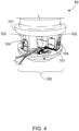
- FIG 4 shows detail of a load cell 80 in Figure 3 , wherein the load cell 80 is a separable unit from the remainder of the first load pad 70, and which can therefore be removed in case of failure. This also enables easier calibration of the load cell 80 prior to its installation within the first load pad 70, at or with a test bench.
- the load cell 80 may comprise a main core 100 having a cross section which is or is almost constant.
- the main core 100 generally has a cylindrical shape.
- the main core 100 preferably comprises top and bottom covers 101, and at least one support or foundation 102 located between the covers 101.
- the main core 100 comprises at least two foundations 102; more optionally four foundations 102, generally in a symmetric configuration between the top and bottom covers 101, as shown in Figure 4 .
- the cross section and the height of the or each foundation 102 enable an accurate measure of the load imposed on the load cell 80.
- the main core of the load cell 80 is machined from one single piece or block of material, so as to form a unitary assembly.
- the top and bottom covers 101 and the foundations 102 shown in Figure 4 could be formed from a single block of suitable material.
- Figure 4 shows a transducer 104 attached to each foundation 102.
- load applied to the first load pad 70 leads to an electrical resistance change of the transducers 104 that is proportional and/or directly proportional to the load applied.
- the transducers 104 are preferably arranged to compensate for any electrical resistance variation induced by such parameters other than the load. Hence the final measurement is preferably not affected by temperature or other such parameters.
- Figures 5a and 5b show a second load pad 110 having a track support portion 112, a pipeline engaging portion 114, and a load sensor 116 located between the track support portion 112 and the pipeline engaging portion 114.
- the pipeline engaging portion 114, load sensor 116 and track support portion 112 may all be machined from one piece or block of suitable material, such as but not limited to, steel. In this way, the pipeline engaging portion 114, load sensor 116 and track support portion 112 are thus 'fixed' together, to provide a more robust and compact load pad.
- the load sensor 116 comprises one or more foundations 118, each foundation 118 optionally having one or more transducers 120 thereon.
- load applied to the load pad 110 leads to an electrical resistance change of the transducer(s) 120 that is proportional and/or directly proportional to the load applied.
- the transducers 120 are preferably arranged to compensate for any electrical resistance variation induced by such parameters other than the load. Hence the final measurement is preferably not affected by temperature or other such parameters.
- there are several transducers 120 per foundation 118 generally five transducers per foundation 118. Having multiple transducers per foundation can provide an improved or more accurate assessment of the overall track performance.
- the load sensor comprises from six to nine foundations.
- Figures 5a and 5b show the second load sensor having nine foundations 118. The number, the cross-section and the height of the or each foundation allow for an accurate measure of the load.
- Figures 6a and 6b show schematic views of a method of monitoring the loading between a subsea pipeline 200 and two opposing continuous tracks 202 of a pipe tensioner (not otherwise shown), such as the pipe tensioner shown in figure 2 .
- FIGS. 6a and 6b show in diagrammatic form each continuous track 202 having a number of conventional tensioner pads 204, and one load pad 206 comprising one or more load sensors according to the present invention, (such as the first and second load sensors 70, 110 described hereinbefore).
- the load pads 206 are in a symmetric and opposing position.
- Figures 6a and 6b show in diagrammatic form movement of the opposing tracks 202 in a known manner, typically in opposing symmetric motion, to move the pipeline 200 downwardly thereinbetween in a manner known in the art.
- Figure 6a shows the movement of the load pads 206 of the present invention to initially engage the pipeline 200 and travel along with the pipeline 200, until they disengage with the pipeline 200 as per Figure 6b after travelling the length of the engagement portion of the pipe tensioner.
- Figures 6a and 6b show moving a subsea pipeline 200 through the pipe tensioner using the opposing continuous tracks 202, and monitoring the passage of the subsea pipeline 200 through the pipe tensioner based on measuring the loading on the or each load pad 206 by monitoring the loading on the tensioner during engagement of the symmetric and opposing load pads 206 against the pipeline 200.
- the method comprises measuring the compressive and shear loadings on the load pads 206.
- Figure 7 shows a continuous, and optionally real time, graph of the continuous measurement of load by the load pads 206 against the position of the pipeline as it passes through the pipe tensioner (and/or against time).
- the peaks show the positions of the supporting hydraulic cylinders.
- figure 7 shows an initial 'zero' loading for the arrangement shown in figure 6a , with the loading rising rapidly to a first peak as the load pads 206 first engage with the pipeline 200.
- the first peak is followed by a small reduction in loading as the load pad 206 travels downwardly with the pipeline 200 between figures 6a and 6b , followed by a second peak as the load pad 206 disengages with the pipeline 200 shown in figure 6b .
- Figure 7 shows a profile of compressive loading along a pipeline, which allows an operator or user to understand how the loading is occurring for that pipeline, and to either confirm its appropriateness, or how the tensioner could perform for the same or similar pipeline.
- This information can be provided by the operator or user modifying or replacing conventional pads in the pipe tensioner, and different load pads can be provided to either replace different types of conventional pads and/or to work with different types of pipe tensioners.
- the data in figure 7 could be provided in real time, by transmission of the load measurements to a suitable processor, such as a nearby laptop or computer, etc., optionally via one or more relays, or the data could be stored the load pads 206 for subsequent downloading and processing.
- a suitable processor such as a nearby laptop or computer, etc.
- the data could be stored the load pads 206 for subsequent downloading and processing.
- the data in figure 7 could also be used as means to calculate or as an indication of fatigue or wear of a part of the pipe tensioner, such as the pad surfaces, the roller bearings, or cylinders, etc., where a different loading profile is detected, and/or to detect any overloading or underloading between the pipeline and the pipe tensioner.
- the present invention could help indicate the presence of ⁇ Field Joint Coatings' as discussed herein, and their correct location, thickness etc, but detected expected variation in the loading. This data could also provide information on the friction behaviour between the pad and the pipeline during laying.
- the present invention provides a pipe tensioner and a method able to measure and optionally record both compressive and shear loading, and to capture the effect of various pipeline types on a pipe tensioner, unlike a standard test piece of pipeline having a strain gauge thereon.
- the data recording can be completed onshore or offshore during live installations in particular based on the use of a wireless data transmitter, and allows additional functionality such as the ability to post-process data live for fatigue and/or load monitoring.
- the present invention also facilitates the testing of long pipe tensioners, which is not possible with known test pipes, which only come in 'standard' short lengths.
- the present invention also allows testing of a pipe tensioner to be carried out at high pipelay speeds, in particular at a full or ⁇ normal ⁇ pipelay speed, again unlike standard test pipes.
- the present invention also allows measuring of a total load applied to a pipeline if the continuous tracks are provided with sufficient loads pads according to the present invention along their lengths.
- the present invention allows data to show the profile of compressive and/or shear loading along a pipeline or track length, which allows an operator or user to foresee loadings of different pipeline products, including rigid pipes or flexible pipes or umbilicals, especially pipeline products of different diameters, and to be prepared for differences in compressive stiffness or frictional behaviour of certain pipelines.
- the present invention can also be applied either in a test environment onshore, or in at test environment offshore or during offshore laying or recovering operations.
- the present invention can also be used to validate predictive modelling of pipeline laying or recovering operations, allowing faster or otherwise quicker actual pipeline laying or recovering operations, saving the large OPEX involved in pipeline laying or recovering operations.
Landscapes
- Engineering & Computer Science (AREA)
- General Engineering & Computer Science (AREA)
- Mechanical Engineering (AREA)
- Physics & Mathematics (AREA)
- General Physics & Mathematics (AREA)
- Chemical & Material Sciences (AREA)
- Analytical Chemistry (AREA)
- Force Measurement Appropriate To Specific Purposes (AREA)
- Earth Drilling (AREA)
Description
- Subsea marine pipelines are well known in the art for transporting fluids, for example hydrocarbons such as oil and gas. Such pipelines can be laid on a seabed or a sea floor for the passage of fluids between two sites, such as a production well or well head and an adjacent production platform. Such pipelines also need to be recovered from a sea bed after use.
- Three methods of laying a pipeline are employed and depend on the depth of the seabed. A first method, called J Lay, consists of constructing the pipeline on a vertical assembly line and laying it in a vertical position. This method is particularly suitable for laying underwater pipelines in very deep water (generally, a depth greater than 1500m). When the seabed is not very deep (generally, a depth of less than 1500m), in a second method called S Lay the pipeline is laid in a horizontal configuration. Subsea pipelines are generally laid from a pipe-laying vessel, sometimes termed a marine pipelay vessel. Where the pipeline has sufficient flexibility, a third method may be employed in which the pipeline can be formed 'onshore' and located on a large storage drum or reel on the pipe-laying vessel for subsequent laying 'off-shore' directly from the reel. This is generally termed in the art `reel-laying'. For this, the pipeline needs to be reeled or spooled both onto and later off from the reel, based on controlled movement, which can be provided by a suitable tensioning assembly.
- For laying, the pipe-laying vessel usually has a marine pipelay assembly thereon, such as a tower, for organising the pipeline from the vessel into the sea. The marine pipelay assembly may control the direction, speed and/or other parameters of the pipeline during its laying operation, and the movement between the pipeline and vessel is generally controlled by one or more apparatus or devices intended to grip and/or apply tension to the pipeline during its passage through the marine pipelay assembly. Suitable devices or apparatus for this purpose are known as "tensioners".
- An example of a tensioner is shown in
FR2964441B1 Figure 1 from this earlier patent is reproduced asFigure 1 of the accompany drawings. Referring toFigure 1 , the tensioner (1A) comprises multiple continuous tracks (10A) which are adapted to engage the pipeline and support at least the weight of the pipeline. The tracks (10A) are each supported by a chassis (13A) which is mounted on a support structure (20A) by cylinders (26A). The cylinders (26A) provide relative movement of the tracks (10A) in order to provide clamping force from the tracks (10A) onto the pipeline. This allows the pipeline to be held in place by friction between the tracks (10A) and the external surface of the pipeline. Each track (10A) comprises multiple pipe tensioner pads (16A) on its external, pipe contacting, surface. The friction is provided by the external, i.e. pipe contacting, surface of each pad, being formed from steel with a roughened surface or ridges or from a material having a relatively high coefficient of friction such as rubber or polyurethane. This pipe contacting surface, and in particular in the case of non-steel pipe contacting surface, is bonded to a rigid back plate, or support, in order to provide the pipe tensioner pad with the required mechanical strength. This back plate is conventionally made of steel. - The clamping force applied by the tensioner on the pipeline is a key parameter in pipe laying. An excessive clamping force may damage the pipeline. On the contrary, insufficient clamping force may lead to an unsuitable or unstable grip of the pipeline, and moving the pipeline in an uncontrolled manner may damage the pipeline and affect security of nearby users or operators. Thus, it is beneficial to measure the clamping force applied by a tensioner.
- It is known to measure the clamping force applied by a tensioner using 'test pipes' having a built-in strain gauge, such that the strain gauge once inserted into a pipe tensioner records local variations in pad loading. However, this is a discrete and indirect methodology, and cannot provide any information concerning variations in pipelines passing through the pipe tensioner. For example, most pipelines to be laid under water, such as rigid pipelines are formed from a series of pipe `stalks' welded to each other, with the welding zone coated to provide additional protection around the weld. This is known as 'field joint coating'. However, the field joint coated section is typically thicker than the other parts of the pipeline, which will create a change in the necessary clamping force which the operator needs to take account of as the pipeline diameter varies during pipeline laying. In addition, axial and side loads cannot be measured with such methodology, but such values would provide beneficial guidance on the behaviour of the pad, and thus on the efficiency of the handling of the pipeline by the tensioner.
-
WO 93/06401A - The "Red Marine Report 2016", Annual Review, discloses an intelligent tensioner pad providing real time verification of pipe friction coefficient and load distribution through a tensioner.
- It is an object of the present invention to provide an improved pipe tensioner and a method of monitoring pipeline loading able to provide `real time' information.
- According to one aspect of the invention, there is provided a pipe tensioner for laying or recovering a subsea pipeline as defined in claim 1.
- According to a second aspect of the invention, there is provided a method of monitoring the loading between a subsea pipelineas defined in claim 11.
- According to a third aspect of the invention, there is provided a marine pipelay assembly comprising a pipe tensioner as defined herein.
- This invention will be further described by reference to the following Figures which are not intended to limit the scope of the invention claimed, in which:
-
Figure 1 shows a prior art tensioner; -
Figure 2 shows a pipe tensioner according to an embodiment of the invention; -
Figure 3 is a perspective view of a first load pad useable in a pipe tensioner according to an embodiment of the invention; -
Figure 4 is a detailed view of a load sensor useable in the first load pad shown inFigure 3 ; -
Figures 5a and 5b are perspective and side views of a second load pad useable in a pipe tensioner according to an embodiment of the present invention; -
Figures 6a and 6b show schematic side views of two positions of a pipeline passing through a pipe tensioner according to an embodiment of the invention, and -
Figure 7 shows a graph of the loading versus load pad position derived fromFigures 6a and 6b . - The present invention provides a pipe tensioner comprising at least two opposing continuous tracks for handling a subsea pipeline, typically being either laying the subsea pipeline from a vessel, or recovering the subsea pipeline onto a vessel, and typically in, on or through a marine pipelay assembly, wherein at least one pad on one of the tracks of the pipe tensioner is a load pad comprising one or more load sensors for measuring loading on the load pad during handling of the subsea pipeline. According to the present invention, the term "laying" encompasses all the operations involved in the laying of the subsea pipeline including, but not limited to, spooling and/or unspooling a subsea pipeline on or from a reel located on a pipe-laying vessel.
- The shape, design, form or arrangement of the pipe tensioner is not limiting on the present invention. A pipe tensioner typically has 2, 3 or 4 opposing continuous tracks, generally in a symmetrical arrangement around a pipeline pathway therethrough. Typically, the pipe tensioner is supported by or within a tower, sometimes termed a pipelay tower, which can be part of the marine pipelay assembly. Such a tower provides the direction or `firing line' for the subsea pipeline, especially during laying.
- It is an expected function of the pipe tensioner to handle the subsea pipeline during laying or recovering with expected amount of control, including at an appropriate speed. Optionally this includes being to be able to hold or pause any pipeline movement when it is desired to carry out one or more other actions during pipeline laying or recovering, such as adding an intermediate unit, device or apparatus into the pipeline, joining pipeline sections or stalks, or conducting known subsea operations on a pipeline. Thus, the pipe tensioner is expected to be able to provide the correct amount of tension in the form of the clamping force at all times.
- Typically, the overall clamping force from the tracks onto the pipeline is provided by cylinders between a tensioner support structure and a chassis for each track, and is distributed between the pads of each tensioner track in contact with the subsea pipeline during laying or recovering of the subsea pipeline. The distribution of the overall clamping force may be uniform or heterogeneous between each of such pads. This overall distributed clamping force is considered to be the loading between the subsea pipeline and the pipe tensioner.
- During the handling and passage of a pipeline through a pipe tensioner, the pad withstands one or more of three main forms of loading, being axial loading (Fx), normal loading (Fz), and side loading (Fy). The axial loading (Fx) is the component of the loading parallel to the longitudinal axis of the pipeline. The normal loading (Fz) is the component of the loading oriented along the radius of the pipeline joining the centre of the pipe contacting surface of the pad. The side loading (Fy) is the component of the loading orthogonal to the axial loading and normal loading. These loads lead to one or more of compressive, shear, torsion and bending stress on the pad. Normal loading on each pad of the continuous tracks can be up to 425 kN, generally between 50 kN and 368 kN; axial loading on each pad of the continuous tracks can be up to 85 kN, generally between 3 kN and 35 kN and side loading on each pad can be up to 95 kN, generally between 0.75 kN and 105 kN. Any variation in the pipeline, in particular in the pipeline diameter, will clearly change the loading between the pipeline and the pipe tensioner.
- The shape, design, form or arrangement of the continuous tracks of the pipe tensioner are not limiting on the present invention, and are generally in the form of an elongate arrangement around one or more end rollers or drums of a support chassis, at least one of which is driven by a suitable drive apparatus or mechanism in order to create `conveyor belt' type movement of the continuous tracks in a manner known in the art. The continuous tracks and their chassis are not further described herein.
- Conventional pads used on conventional continuous tracks of a pipe tensioner are well known in the art. A conventional pad typically comprises a track support portion and a pipeline engaging portion. The track support portion may include a base or a plate, such as a base plate or a back plate, which can be rigid, and which is designed to provide the engagement and securement of the pad to the continuous track using one or more known fittings or fixtures.
- The pipeline engaging portion of a conventional pad can have a pipe contacting surface formed from a material with a relative high coefficient of friction, such as rubber or polyurethane or steel. The pipe contacting surface may also comprise a roughened surface or ridges or the like, to assist engagement between the pad and the pipeline. The uppermost part of the pipeline engaging portion, such as any pipe contacting surface, can be shaped to improve the contact of the pad with a pipeline, such as having a valley which, in use, extends in a direction parallel to a longitudinal axis of the pipeline contacted by the surface and angled pipe engaging surfaces, in a manner known in the art. The longitudinal axis of the pipeline is that extending along the length of the pipeline.
- A conventional pad can also have a housing arranged between a pipeline engaging portion and a track support portion. Such housing may be of any suitable shape such as a rectangular, circular or T shape. The housing may be formed of any suitable material such as plastics or metals. The intermediate housing may be secured to the pipeline engaging portion and/or to the track support portion by any means such as pins, bolts or adhesive.
- A conventional pad can also have a spring block between the track support portion and the intermediate housing for providing the expected resilience of a pad. The spring block may be any suitable shape such as but not limited to rectangular shape, circular shape. The spring block may be formed of any suitable material such as rubber or polyurethane. Typically, the spring block transfers the pipeline load to the housing, which then transfers the load to the pipeline engaging portion. This can be done by contact between the housing and the pipeline engaging portion and/or through a shear key managed on the upper face of the housing.
- Generally, the overall height of a conventional pad is between 100 mm and 250 mm, in particular between 200 mm and 250 mm. The overall height is measured from the lower part of a valley-line of the pipe contacting surface to the track support portion. The length of the conventional pad is generally between 150 mm and 250 mm, and the width is generally between 200 mm and 400 mm.
- Generally, the stiffness of a conventional pad is between 9 kN/mm and 90 kN/mm, such as between 10 kN/mm and 25 kN/mm.
- The present invention is defined by at least one pad of a pipe tensioner being a load pad comprising one or more load sensors. The term "load pad" is used herein to define a pad for a pipe tensioner that comprises one or more load sensors, able to monitor and preferably to provide at least one measurement of loading between a subsea pipeline and a pipe tensioner.
- The load pad may have suitable shape, design, form or arrangement, within the requirement of being securable to a continuous track, and optionally matching with the or any conventional pads on the continuous tracks.
- Optionally, a load pad has the same or similar height, width and length dimensions of a conventional pad, such that it can be directly used in an existing pipe tensioner through replacement of a conventional pad with a load pad. This also ensures that the load measured by the load pad is a `real' load, i.e. the same as or similar to the load experienced by a conventional pad, which adds to the reliability and accuracy of the measurements provided.
- The present invention is not limited by the number of load pads added to each, or some of, or all of the continuous tracks of the pipeline tensioner. A pipe tensioner having a plurality of continuous tracks may comprise a different number of load pads on each or some or all of the continuous tracks, including no load pads. Optionally, each pad of at least one of the continuous tracks, optionally both of the continuous tracks, is a load pad. Further optionally, each pad of a continuous track is a load pad.
- Load sensors for measuring loading, are well known in the art. Typically, a load sensor includes a transducer that creates an electrical signal whose magnitude is proportional, typically directly proportional, to the force being applied to the load sensor. The electrical signal output can be one or more of the group comprising: a voltage change, a current change, or a frequency change, depending on the load sensor being used. Any electrical signal is typically small, for example being in the magnitude of millivolts, etc., and typically requires amplification. Load sensors can be provided in a range of shapes, sizes and dimensions.
- Optionally, at least one load pad measures one or more of the group comprising: axial loading (Fx), normal loading (Fz) and side loading (Fy).
- Optionally, the load pad has the same form of attachment and securement to a continuous track as a conventional pad. The or each load pad used in the present invention comprises a track support portion and a pipeline engaging portion. The track support portion may include a base or a plate, such as a base plate or a back plate, in particular being rigid, and being able to provide the engagement and securement of the load pad to the continuous track. The track support portion may include one or more fixtures, fittings or apertures, able to allow one or more engagement pieces such as screws, bolts, pins, hooks or other fasteners, to achieve the engagement and securement of the load pad with the continuous track.
- The pipeline engaging portion preferably has a pipe contacting surface formed from a material with a relative high coefficient of friction, such as rubber or polyurethane. Optionally, the uppermost part of the pipeline engaging portion such as any pipe contacting surface, is shaped to improve the contact of the load pad with a pipeline, such as having a valley and angled pipe engaging surfaces, in a manner known in the art.
- Optionally, the inner surface of the pipe contacting surface is shaped or machined to fit one or more load sensors.
- Optionally the external surface of the pipe contacting surface of a load pad is the same as a conventional pad.
- Optionally, the load pad further includes an intermediate portion between a tracked support portion and a pipeline engaging portion, said intermediate portion including a housing or housings for one or more load sensors. The housing or housings may be formed integrally with either any tracked support portion or any pipeline engaging portion or both.
- The load sensors are located between the pipeline engaging portion and the intermediate portion of a load pad.
- Optionally there is no contact between the tracked support portion and a pipeline engaging portion other than through the or each load sensor. This provides a more accurate measure or measurement of the load or loads by the or each load sensor. Preferably, there is at least one clearance between the track support portion and the pipeline engaging portion.
- Optionally, one or more of the group comprising a tracked support portion, a pipeline engaging portion, and an intermediate portion, are separable. A tracked support portion and a pipeline engaging portion and any intermediate portion may be releasably or non-releasably securable together using one or more securing means, including one or more from the group comprising: adhesives, pins, bolts, screws and fasteners. According to the example in which the securing means are pins, bolts or screws, the load pad preferably comprises 4 securing means.
- In one embodiment of the present invention, there is a load sensor located between the intermediate housing and the pipeline engaging portion, and clearance between the intermediate housing and the pipeline engaging portion, to ensure that the overall loading is transferred to the load sensor. Such an arrangement has the additional advantage of reducing the need to remove the load sensor frequently, due to wear of the pipeline engaging portion. According to the example in which the securing means are pins, bolts or screws, the said securing means comprise a rod preferably extending through a bore formed in the pipeline engaging portion. Preferably, there is also a clearance between the bore and the rod to prevent the rod from withstanding loads during handling of the pipeline, the overall loads being transferred from the pipeline engaging portion to the intermediate portion through the load sensors.
- Optionally, at least one load sensor is a load cell. Optionally the load cell is a three axis load cell. The compressive stiffness of the load cell should be at least superior to the compressive stiffness of a conventional pad. This should achieve more accurate and reliable measurement of the loading. The overall stiffness of the load pad should be the same or similar to the overall stiffness of a conventional pad, such as within +/- 1% of the stiffness of the conventional pad.
- Optionally, the or each load pad has at least 3 load sensors to increase the sensitivity of the load pad. Further optionally, the or each load pad has 4 load sensors to improve the stability of the load pad. Preferably the four load sensors are symmetrically located within the load pad.
- Optionally, the pipe tensioner comprises one or more data recorders/storage media, data transmitters or both.
- Data generated by a load pad can either be stored in any suitable data recorder/storage medium which may be proximate to and/or on and/or in the load pad, or could be transmitted, via any suitable transmission medium, wired or wireless, from the load pad to a separate location for storage and/or processing, or for further re-laying, or any combination thereof.
- A data recorder/storage medium may comprise any form of data recording or memory device or apparatus, typically a memory chip or device or the like, able to record and/or store data for subsequent processing. Optionally, data on the data recorder is downloaded or relayed to an appropriate receiver for storage and/or processing and/or further relaying or transmission.
- Optionally, a data transmitter includes one or more transmitters, optionally with an aerial, able to transmit data from the load pad to an appropriate receiver. An example includes wireless transmission to a wireless receiver either partly or fully located on the pipe tensioner or adjacent thereto or remote therefrom. Examples of wireless data transmission technologies include but are not limited to wi-fi, based on the IEEE 802.11 standards, and Bluetooth.
- Optionally, the pipe tensioner includes one or more relay units or apparatus, able to relay data or other information from the load pad to one or more remote locations, such as the user or operator of the pipe tensioner, or a suitable control room or remote control location, via any suitable transmission medium, wired or wireless.
- Optionally, the load pad comprises a wireless data transmitter. Optionally the wireless data transmitter is releasably secured to the intermediate housing. The wireless data transmitter can transmit real-time or buffered data generated by the load pad, or data that has been stored locally by the load pad prior to transmission. The data can be transmitted from the load pad to any one or more of the data recorders/storage media or relay units or the like mentioned.
- Optionally, the load pad comprises a power pack for supplying power to the wireless data transmitter. Optionally, the power pack is releasably secured to the intermediate housing. Optionally, the wireless data transmitter and the power pack are releasably secured to opposite sides of the intermediate housing for improving the stability of the load pad.
- The present invention also provides a method of monitoring the loading between a subsea pipeline and a pipe tensioner as described herein.
- Subsea pipelines have been initially discussed herein, and are typically elongate, optionally having a length of many metres, including many kilometres, with a regular, typically circular, outer surface. The outer surface of the subsea pipeline is typically one or more coatings or protective sheaths, generally a polymeric protective sheath, against which the pads of a pipe tensioner engage. The subsea pipeline may be for transporting fluids and/ or other underwater services, including subsea or seabed communications or chemical supply. The present invention is not limited by the nature of the subsea pipeline. Thus, the subsea pipeline includes a rigid subsea pipeline as well as a flexible subsea pipeline.
- In the method of monitoring the loading, at least one of the pads of at least one of opposing continuous tracks is a load pad comprising one or more load sensors. The nature and action of a load pad and a load sensor are described herein, and apply equally to the method of measuring the loading according to the present invention.
- The method also comprises the step of measuring the loading on the or each load pad. The measuring can be carried out using any suitable process or arrangement, typically based on the loading between a subsea pipeline and the load pad causing a deformation or strain on the one or more load sensors, which provide a measurement for example in the form of one or more electrical signal outputs, which can be measured and preferably recorded, either locally or remotely.
- Optionally, the method of the present invention further comprises the step of relaying the measuring of the loading to another processor and/or location.
- The measuring of the loading may comprise a single figure or value, or may comprise a plurality of measurements or values, which can either be processed individually or processed in an aggregate manner, to provide a final measurement or set of data.
- For example, a measurement of the 'normal' loading can help to indicate how the clamping force of the tensioner is distributed on the pipe. Such information can help to detect any overload on a pad or the pipe, such as on a field joint coating zone or a lack of clamping.
- And/or a measurement of the axial loading can help indicate how the overall clamping force is withstanding, and how it is distributed between each pad and/or within a pad and/or on the pipe.
- In addition, during pipe laying, wave motion may result in large and repetitive tensile stress variations of the pipe that can lead to fatigue of said pipe. Hence, axial load measurement can help provide guidance on tensile stress variations during pipe laying and thus a better understanding of the fatigue of the pipe during laying. Such data can be used subsequently for validating pipe design or for improving its design for future projects. Meanwhile, a measurement of the side loading can help indicate distribution of the clamping force within a pad.
- According to one embodiment of the present invention, the method of the present invention further comprises real time measuring of the loading. The real time measuring can be carried out either intermittently, continuously, or a combination of the same, optionally with regular or irregular periodic frequency, or periodic changes thereinbetween. Optionally, the operator of the pipe tensioner is able to measure the loading between a subsea pipeline and the pipe tensioner in a pre-determined arrangement, regime or sequence, and/or during handling of the subsea pipeline passing through the pipe tensioner. Optionally, the time or timing of the measuring of the loading is variable during use of the pipe tensioner to allow the operator to vary the measuring, and to have variation in the data provided by the method of the present invention.
- Optionally, the method of the present invention comprises continuous measuring of the loading, in particular during passage of a subsea pipeline through the pipe tensioner.
- Optionally, the method of the present invention further comprises the steps of:
- providing at least one pad as a load pad able to measure one or more of the group comprising: axial loading, normal loading and side loading; and
- measuring one or more loadings on the load pad.
- The nature and design of the one or more load pads are described herein, and apply equally to the method of the present invention.
- Optionally, the method of the present invention comprises measuring and recording of the loading of each load pad in the pipe tensioner.
- Optionally, the method of the present invention comprising measuring the loading along at least one axis of the load pad, further optionally all three axes of the load pad.
- Optionally, the method further comprises transferring the overall loading from the track support portion to the pipeline engaging portion through the one or more load cells, and measuring the loading on the load pad using the one or more load cells. The nature and design of a track support portion and a pipeline engaging portion are described herein, and apply equally to the method of the present invention. Further optionally, the load pad includes an intermediate portion, optionally having a housing for one or more load cells, as further described herein.
- Optionally, the method of the present invention further comprises the steps of:
- moving a subsea pipeline through the pipe tensioner using the opposing continuous tracks; and
- monitoring the passage of the subsea pipeline through the pipe tensioner based on measuring the loading on the or each load pad.
- Optionally, the method of the present invention comprises a pipeline tensioner having at least two, such as two or four, opposing tracks, each track has at least one load pad in a symmetric and opposing position, and further comprising the steps of:
- moving a subsea pipeline through the pipe tensioner using the opposing continuous tracks; and
- monitoring the loading on the tensioner during engagement of the symmetric and opposing load pads against the pipeline.
- The present invention also provides a marine pipelay assembly comprising a pipe tensioner as defined herein. Typically, the marine pipelay assembly includes a tower, which tower includes the pipe tensioner. The marine pipelay assembly is typically arranged on a sea-going vessel, either being a ship or a barge or similar, and may also be moveable, in particular rotational to provide an 'angled' pipeline laying direction in relation to a vessel. The marine pipelay assembly may include one or more other supports, chassis, or pipe tensioners in line with the pipe tensioner of the present invention.
-
Figure 2 shows a simplified version of apipe tensioner 30 being similar to thetensioner 1A shown infigure 1 , and comprising multiplecontinuous tracks 32 which are adapted to engage a subsea pipeline (not shown) and support at least the weight of the pipeline as it travels either in the direction F as shown or an opposite direction. - The
continuous tracks 32 are driven by motors (not shown), and are each supported by achassis 34 mounted on asupport structure 36 bycylinders 38. Thecylinders 38 provide relative movement of thetracks 32 in order to provide clamping force between thetracks 32 and the pipeline. - Each
continuous track 32 comprises multiple conventionalpipe tensioner pads 40, and at least oneload pad 42 comprising one or more load sensors, examples of which are described hereinafter. - The
pipe tensioner 30 can be part of a marine pipelay assembly. -
Figure 3 shows afirst load pad 70 useable in the present invention. Thefirst load pad 70 has apipeline engaging portion 72, anintermediate housing 74, and abase plate 76. Thefirst load pad 70 also has aspring block 90. - The
pipeline engaging portion 72 may be formed of an upper casting, typically having a valley-line shape to assist engagement with a pipeline in use. - The
intermediate housing 74 houses fourload cells 80 located between an upper surface of theintermediate housing 74 and thepipeline engaging portion 72. In particular, eachload cell 80 is bolted to theintermediate housing 74 and thepipeline engaging portion 72. - The
first load pad 70 can be used as theload pad 42 in thepipe tensioner 30 shown infigure 2 . Thebase plate 76 of thefirst load pad 70 includes apertures for securement of thefirst load pad 70 to a continuous track. Thespring block 90 is secured between thebase plate 76 and theintermediate housing 74. Thespring block 90 has a rectangular body with a central hollow core. -
Figure 3 also shows thefirst load pad 70 having apower pack 86 and awireless transmitter 88. Thepower pack 86 can provide power required to operate thewireless transmitter 88. Thewireless transmitter 88 provides the ability to send a measurement or data in the form of a signal to a suitable remote data logger for processing, or to a suitable relay located nearby on the pipe tensioner. Thepower pack 86 and thewireless transmitter 88 are secured to the sides of theintermediate housing 74 bybolts 84. -
Figure 4 shows detail of aload cell 80 inFigure 3 , wherein theload cell 80 is a separable unit from the remainder of thefirst load pad 70, and which can therefore be removed in case of failure. This also enables easier calibration of theload cell 80 prior to its installation within thefirst load pad 70, at or with a test bench. - The
load cell 80 may comprise amain core 100 having a cross section which is or is almost constant. Themain core 100 generally has a cylindrical shape. Themain core 100 preferably comprises top and bottom covers 101, and at least one support orfoundation 102 located between thecovers 101. Optionally, themain core 100 comprises at least twofoundations 102; more optionally fourfoundations 102, generally in a symmetric configuration between the top and bottom covers 101, as shown inFigure 4 . - Optionally, the cross section and the height of the or each
foundation 102 enable an accurate measure of the load imposed on theload cell 80. - In one embodiment of the present invention, the main core of the
load cell 80 is machined from one single piece or block of material, so as to form a unitary assembly. For example, the top and bottom covers 101 and thefoundations 102 shown inFigure 4 could be formed from a single block of suitable material. -
Figure 4 shows atransducer 104 attached to eachfoundation 102. Generally, load applied to thefirst load pad 70 leads to an electrical resistance change of thetransducers 104 that is proportional and/or directly proportional to the load applied. As various parameters (such as temperature) may also induce electrical resistance variation, thetransducers 104 are preferably arranged to compensate for any electrical resistance variation induced by such parameters other than the load. Hence the final measurement is preferably not affected by temperature or other such parameters. -
Figures 5a and 5b show asecond load pad 110 having atrack support portion 112, apipeline engaging portion 114, and aload sensor 116 located between thetrack support portion 112 and thepipeline engaging portion 114. Thepipeline engaging portion 114,load sensor 116 andtrack support portion 112, may all be machined from one piece or block of suitable material, such as but not limited to, steel. In this way, thepipeline engaging portion 114,load sensor 116 andtrack support portion 112 are thus 'fixed' together, to provide a more robust and compact load pad. - Optionally in the
second load pad 110, theload sensor 116 comprises one ormore foundations 118, eachfoundation 118 optionally having one ormore transducers 120 thereon. Generally, load applied to theload pad 110 leads to an electrical resistance change of the transducer(s) 120 that is proportional and/or directly proportional to the load applied. Again, as various parameters (such as temperature) may also induce electrical resistance variation, thetransducers 120 are preferably arranged to compensate for any electrical resistance variation induced by such parameters other than the load. Hence the final measurement is preferably not affected by temperature or other such parameters. Typically, there areseveral transducers 120 perfoundation 118, generally five transducers perfoundation 118. Having multiple transducers per foundation can provide an improved or more accurate assessment of the overall track performance. - Optionally, the load sensor comprises from six to nine foundations.
Figures 5a and 5b show the second load sensor having ninefoundations 118. The number, the cross-section and the height of the or each foundation allow for an accurate measure of the load. -
Figures 6a and 6b show schematic views of a method of monitoring the loading between asubsea pipeline 200 and two opposingcontinuous tracks 202 of a pipe tensioner (not otherwise shown), such as the pipe tensioner shown infigure 2 . -
Figures 6a and 6b show in diagrammatic form eachcontinuous track 202 having a number ofconventional tensioner pads 204, and oneload pad 206 comprising one or more load sensors according to the present invention, (such as the first andsecond load sensors load pads 206 are in a symmetric and opposing position. -
Figures 6a and 6b show in diagrammatic form movement of the opposingtracks 202 in a known manner, typically in opposing symmetric motion, to move thepipeline 200 downwardly thereinbetween in a manner known in the art. -
Figure 6a shows the movement of theload pads 206 of the present invention to initially engage thepipeline 200 and travel along with thepipeline 200, until they disengage with thepipeline 200 as perFigure 6b after travelling the length of the engagement portion of the pipe tensioner. - Thus,
Figures 6a and 6b show moving asubsea pipeline 200 through the pipe tensioner using the opposingcontinuous tracks 202, and monitoring the passage of thesubsea pipeline 200 through the pipe tensioner based on measuring the loading on the or eachload pad 206 by monitoring the loading on the tensioner during engagement of the symmetric and opposingload pads 206 against thepipeline 200. Optionally the method comprises measuring the compressive and shear loadings on theload pads 206. -
Figure 7 shows a continuous, and optionally real time, graph of the continuous measurement of load by theload pads 206 against the position of the pipeline as it passes through the pipe tensioner (and/or against time). The peaks show the positions of the supporting hydraulic cylinders. Thus,figure 7 shows an initial 'zero' loading for the arrangement shown infigure 6a , with the loading rising rapidly to a first peak as theload pads 206 first engage with thepipeline 200. The first peak is followed by a small reduction in loading as theload pad 206 travels downwardly with thepipeline 200 betweenfigures 6a and 6b , followed by a second peak as theload pad 206 disengages with thepipeline 200 shown infigure 6b . -
Figure 7 shows a profile of compressive loading along a pipeline, which allows an operator or user to understand how the loading is occurring for that pipeline, and to either confirm its appropriateness, or how the tensioner could perform for the same or similar pipeline. This information can be provided by the operator or user modifying or replacing conventional pads in the pipe tensioner, and different load pads can be provided to either replace different types of conventional pads and/or to work with different types of pipe tensioners. - The data in
figure 7 could be provided in real time, by transmission of the load measurements to a suitable processor, such as a nearby laptop or computer, etc., optionally via one or more relays, or the data could be stored theload pads 206 for subsequent downloading and processing. - The data in
figure 7 could also be used as means to calculate or as an indication of fatigue or wear of a part of the pipe tensioner, such as the pad surfaces, the roller bearings, or cylinders, etc., where a different loading profile is detected, and/or to detect any overloading or underloading between the pipeline and the pipe tensioner. For example, the present invention could help indicate the presence of `Field Joint Coatings' as discussed herein, and their correct location, thickness etc, but detected expected variation in the loading. This data could also provide information on the friction behaviour between the pad and the pipeline during laying. - The present invention provides a pipe tensioner and a method able to measure and optionally record both compressive and shear loading, and to capture the effect of various pipeline types on a pipe tensioner, unlike a standard test piece of pipeline having a strain gauge thereon. The data recording can be completed onshore or offshore during live installations in particular based on the use of a wireless data transmitter, and allows additional functionality such as the ability to post-process data live for fatigue and/or load monitoring.
- The present invention also facilitates the testing of long pipe tensioners, which is not possible with known test pipes, which only come in 'standard' short lengths.
- The present invention also allows testing of a pipe tensioner to be carried out at high pipelay speeds, in particular at a full or `normal `pipelay speed, again unlike standard test pipes.
- The present invention also allows measuring of a total load applied to a pipeline if the continuous tracks are provided with sufficient loads pads according to the present invention along their lengths.
- The present invention allows data to show the profile of compressive and/or shear loading along a pipeline or track length, which allows an operator or user to foresee loadings of different pipeline products, including rigid pipes or flexible pipes or umbilicals, especially pipeline products of different diameters, and to be prepared for differences in compressive stiffness or frictional behaviour of certain pipelines.
- The present invention can also be applied either in a test environment onshore, or in at test environment offshore or during offshore laying or recovering operations.
- The present invention can also be used to validate predictive modelling of pipeline laying or recovering operations, allowing faster or otherwise quicker actual pipeline laying or recovering operations, saving the large OPEX involved in pipeline laying or recovering operations.
Claims (20)
- A pipe tensioner (30) for laying or recovering a subsea pipeline comprising at least two opposing continuous tracks (32) able to hold the subsea pipeline, each track having a plurality of pads (40) mounted on the continuous track for contacting the subsea pipeline, and at least one pad of said plurality of pads is a load pad (42) comprising one or more load sensors for measuring loading on the load pad during handling of the subsea pipeline,
characterised in that the or each load pad comprises a track support portion (112) and a pipeline engaging portion (114), and wherein at least one load sensor (116) is located between the track support portion (112) and the pipeline engaging portion (114). - A pipe tensioner (30) as claimed in claim 1, wherein each pad (40) of at least one of the continuous tracks (32), optionally both of the continuous tracks, is a load pad (42).
- A pipe tensioner (30) as claimed in claim 1 or claim 2, wherein at least one load pad (42) measures one or more of the group comprising: axial loading, normal loading and side loading.
- A pipe tensioner (30) as claimed in claim 1 comprising clearance between the track support portion (112) and the pipeline engaging portion (114).
- A pipe tensioner (30) as claimed in any one of the preceding claims wherein at least one load sensor (72) is a load cell (80).
- A pipe tensioner (30) as claimed in claim 5, wherein at least one of the load cell (80) is a three axis load cell.
- A pipe tensioner (30) as claimed in any one of the preceding claims, wherein the or each load pad (42) has at least three load sensors.
- A pipe tensioner (30) as claimed in any one of the preceding claims 1 to 6, wherein the or each load pad has four load sensors.
- A pipe tensioner (30) as claimed in any one of the preceding claims further comprising one or more data recorders, data transmitters, or both.
- A pipe tensioner (30) as claimed in claim 9 wherein the load pad comprises a wireless data transmitter (88).
- A method of monitoring the loading between a subsea pipeline (200), and a pipe tensioner (30) for laying or recovering the subsea pipeline, the pipe tensioner comprising at least two opposing continuous tracks (202) able to hold the subsea pipeline, and each track having a plurality of pads (204) mounted on the continuous track for contacting the subsea pipeline, comprising at least the steps of:providing at least one pad of said plurality of pads as a load pad (206) comprising a track support portion (112) and a pipeline engaging portion (114), one or more load sensors located between the track support portion (112) and the pipeline engaging portion (114) for measuring loading on the load pad during handling of the subsea pipeline; andmeasuring the loading on the or each load pad.
- A method as claimed in claim 11 further comprising the step of relaying the measuring of the loading to another location.
- A method as claimed in claim 11 further comprising the step of recording the measuring of the loading on the load pad (206).
- A method as claimed in any one of claims 11 to 13 further comprising real time measuring of the loading.
- A method as claimed in any one of claims 11 to 14 further comprising continuous measuring of the loading.
- A method as claimed in any one of claims 11 to 15 further comprising the steps of:providing at least one pad (204) as a load pad (206) able to measure one or more of the group comprising: axial loading, normal loading and side loading; andmeasuring one or more loadings on the load pad.
- A method as claimed in any one of claims 11 to 16 further comprising the steps of:transferring the overall loading from the track support portion to the pipeline engaging portion through the one or more load cells; andmeasuring the loading on the load pad using the one or more load cells.
- A method as claimed in any one of claims 11 to 17 further comprising the steps of:moving a subsea pipeline (200) through the pipe tensioner (30) using the opposing continuous tracks (202); andmonitoring the passage of the subsea pipeline through the pipe tensioner based on measuring the loading on the or each load pad (206).
- A method as claimed in any one of claims 11 to 18 wherein the pipe tensioner (30) has two or four opposing tracks (202), each track has at least one load pad (206) in a symmetric and opposing position, and further comprising the steps of:moving a subsea pipeline (200) through the pipe tensioner using the opposing continuous tracks; andmonitoring the loading on the tensioner during engagement of the symmetric and opposing load pads against the pipeline.
- A marine pipelay assembly comprising a pipe tensioner (30) as defined in any one of claims 1 to 10.
Applications Claiming Priority (2)
| Application Number | Priority Date | Filing Date | Title |
|---|---|---|---|
| GB1705887.6A GB2561375B (en) | 2017-04-12 | 2017-04-12 | Pipe Tensioner |
| PCT/IB2017/001386 WO2018189567A1 (en) | 2017-04-12 | 2017-10-04 | Pipe tensioner |
Publications (3)
| Publication Number | Publication Date |
|---|---|
| EP3609827A1 EP3609827A1 (en) | 2020-02-19 |
| EP3609827B1 true EP3609827B1 (en) | 2024-04-03 |
| EP3609827B8 EP3609827B8 (en) | 2024-05-29 |
Family
ID=58744740
Family Applications (1)
| Application Number | Title | Priority Date | Filing Date |
|---|---|---|---|
| EP17804938.3A Active EP3609827B8 (en) | 2017-04-12 | 2017-10-04 | Pipe tensioner |
Country Status (7)
| Country | Link |
|---|---|
| US (1) | US11543055B2 (en) |
| EP (1) | EP3609827B8 (en) |
| CN (1) | CN110678407B (en) |
| AU (1) | AU2017409192B2 (en) |
| GB (1) | GB2561375B (en) |
| MY (1) | MY196563A (en) |
| WO (1) | WO2018189567A1 (en) |
Families Citing this family (4)
| Publication number | Priority date | Publication date | Assignee | Title |
|---|---|---|---|---|
| GB2583953B (en) | 2019-05-15 | 2021-10-13 | Subsea 7 Do Brasil Servicos Ltda | Monitoring squeeze pressure of track tensioners |
| GB2601290B (en) | 2020-10-07 | 2023-11-29 | Aquatec Group Ltd | Strain monitor |
| CN114721103A (en) * | 2020-11-17 | 2022-07-08 | 商海林 | Integrated stable transmission type push-pull optical cable tractor |
| CN115683419B (en) * | 2021-07-27 | 2024-05-28 | 中国石油天然气集团有限公司 | Tension testing method and system for marine pipe-laying marine tensioner |
Family Cites Families (16)
| Publication number | Priority date | Publication date | Assignee | Title |
|---|---|---|---|---|
| FR2089215A5 (en) | 1970-04-09 | 1972-01-07 | Saipem Spa | |
| US3658222A (en) * | 1970-10-21 | 1972-04-25 | Mcdermott & Co Inc J Ray | Pipe tensioning apparatus |
| US3685306A (en) * | 1970-10-29 | 1972-08-22 | Texaco Inc | Subsea pipe laying apparatus and method |
| NO164132C (en) * | 1986-03-10 | 1990-08-29 | Alcatel Stk As | PROCEDURE AND MEASUREMENT EQUIPMENT FOR THE ELECTRIC POWER CABLE HANDLING. |
| GB9120432D0 (en) * | 1991-09-25 | 1991-11-06 | Stena Offshore Ltd | Reel pipelaying vessel |
| US5573353A (en) | 1994-05-24 | 1996-11-12 | J. Ray Mcdermott, S.A. | Vertical reel pipe laying vessel |
| NZ516399A (en) | 1999-07-21 | 2003-08-29 | Saipem S | Improvements in and relating to underwater pipe-laying |
| FR2902411B1 (en) * | 2006-06-19 | 2011-02-25 | Technip France | DEVICE FOR TRANSFERRING A FLUID TO A VESSEL, ASSEMBLY AND TRANSFER METHOD THEREOF |
| CN101918745B (en) * | 2008-01-11 | 2012-09-26 | 伊特里克公司 | marine tensioner |
| US7673739B2 (en) | 2008-02-04 | 2010-03-09 | Honeywell International Inc. | Apparatus and method for in-belt conveyor idler condition monitoring |
| CN201636435U (en) * | 2010-04-14 | 2010-11-17 | 天津俊昊海洋工程有限公司 | Tensioner used for ocean pipe laying ship |
| FR2964441B1 (en) * | 2010-09-07 | 2012-08-24 | Technip France | DEVICE FOR TENSIONING TUBULAR PIPES |
| US9399895B2 (en) | 2011-09-02 | 2016-07-26 | National Oilwell Varco L.P. | Coiled tubing injector head with chain guides |
| CN102562059B (en) | 2011-12-24 | 2014-08-27 | 中国煤炭科工集团太原研究院 | Non-contact monitoring device and non-contact monitoring method for load process of coal-mine excavating mechanical track walking system |
| EP3137801B1 (en) * | 2014-04-29 | 2018-07-04 | Itrec B.V. | Marine reel lay method pipeline installation vessel and methods |
| CN104696588B (en) * | 2015-03-24 | 2017-04-19 | 中国海洋石油总公司 | Deepwater subsea pipeline starting laying method |
-
2017
- 2017-04-12 GB GB1705887.6A patent/GB2561375B/en active Active
- 2017-10-04 MY MYPI2019006043A patent/MY196563A/en unknown
- 2017-10-04 AU AU2017409192A patent/AU2017409192B2/en active Active
- 2017-10-04 CN CN201780091331.2A patent/CN110678407B/en active Active
- 2017-10-04 US US16/604,582 patent/US11543055B2/en active Active
- 2017-10-04 EP EP17804938.3A patent/EP3609827B8/en active Active
- 2017-10-04 WO PCT/IB2017/001386 patent/WO2018189567A1/en not_active Ceased
Non-Patent Citations (2)
| Title |
|---|
| ORREL JOE: "Red Marine Report 2016", 4 October 2016 (2016-10-04), SlideShare Website, XP055970794, Retrieved from the Internet <URL:https://www.slideshare.net/JoeOrrell/red-marine-report-web#> [retrieved on 20221013] * |
| RED MARINE: "Red Marine Report 2016", 28 February 2017 (2017-02-28), Retrieved from the Internet <URL:http://www.redengineers.co.uk/wp-content/uploads/2017/02/Red-Marine-Report-web.pdf> [retrieved on 20201015] * |
Also Published As
| Publication number | Publication date |
|---|---|
| MY196563A (en) | 2023-04-19 |
| CN110678407B (en) | 2021-08-17 |
| US20210116051A1 (en) | 2021-04-22 |
| AU2017409192B2 (en) | 2024-04-11 |
| EP3609827A1 (en) | 2020-02-19 |
| WO2018189567A1 (en) | 2018-10-18 |
| GB2561375B (en) | 2019-11-27 |
| CN110678407A (en) | 2020-01-10 |
| AU2017409192A1 (en) | 2019-11-07 |
| EP3609827B8 (en) | 2024-05-29 |
| BR112019021440A2 (en) | 2020-05-05 |
| GB201705887D0 (en) | 2017-05-24 |
| GB2561375A (en) | 2018-10-17 |
| US11543055B2 (en) | 2023-01-03 |
Similar Documents
| Publication | Publication Date | Title |
|---|---|---|
| AU2017409192B2 (en) | Pipe tensioner | |
| US7461561B2 (en) | Apparatuses and methods for monitoring stress in steel catenary risers | |
| US7698937B2 (en) | Method and apparatus for detecting defects in oilfield tubulars | |
| NL1041668B1 (en) | Real-time tracking and mitigating of bending fatigue in coiled tubing | |
| US9670768B2 (en) | Real-time tracking of bending fatigue in coiled tubing | |
| US8708602B2 (en) | System and methods for stabilizing subsea pipeline | |
| US20200080416A1 (en) | Fatigue Monitoring Of Coiled Tubing In Downline Deployments | |
| EP3969794B1 (en) | Tensioner system for holding-back elongate products and method of monitoring a tensioner system when holding-back elongate products | |
| GB2566001A (en) | Condition monitoring device and safety system | |
| BR112019021440B1 (en) | PIPE TENSIONER, METHOD OF MONITORING LOADING BETWEEN A SUBSEA DUCT AND A PIPE TENSIONER, AND MARINE PIPE LAUNCH ASSEMBLY |
Legal Events
| Date | Code | Title | Description |
|---|---|---|---|
| STAA | Information on the status of an ep patent application or granted ep patent |
Free format text: STATUS: UNKNOWN |
|
| STAA | Information on the status of an ep patent application or granted ep patent |
Free format text: STATUS: THE INTERNATIONAL PUBLICATION HAS BEEN MADE |
|
| PUAI | Public reference made under article 153(3) epc to a published international application that has entered the european phase |
Free format text: ORIGINAL CODE: 0009012 |
|
| STAA | Information on the status of an ep patent application or granted ep patent |
Free format text: STATUS: REQUEST FOR EXAMINATION WAS MADE |
|
| 17P | Request for examination filed |
Effective date: 20191015 |
|
| AK | Designated contracting states |
Kind code of ref document: A1 Designated state(s): AL AT BE BG CH CY CZ DE DK EE ES FI FR GB GR HR HU IE IS IT LI LT LU LV MC MK MT NL NO PL PT RO RS SE SI SK SM TR |
|
| AX | Request for extension of the european patent |
Extension state: BA ME |
|
| TPAC | Observations filed by third parties |
Free format text: ORIGINAL CODE: EPIDOSNTIPA |
|
| DAV | Request for validation of the european patent (deleted) | ||
| DAX | Request for extension of the european patent (deleted) | ||
| STAA | Information on the status of an ep patent application or granted ep patent |
Free format text: STATUS: EXAMINATION IS IN PROGRESS |
|
| 17Q | First examination report despatched |
Effective date: 20201023 |
|
| GRAP | Despatch of communication of intention to grant a patent |
Free format text: ORIGINAL CODE: EPIDOSNIGR1 |
|
| STAA | Information on the status of an ep patent application or granted ep patent |
Free format text: STATUS: GRANT OF PATENT IS INTENDED |
|
| INTG | Intention to grant announced |
Effective date: 20231013 |
|
| GRAS | Grant fee paid |
Free format text: ORIGINAL CODE: EPIDOSNIGR3 |
|
| GRAA | (expected) grant |
Free format text: ORIGINAL CODE: 0009210 |
|
| STAA | Information on the status of an ep patent application or granted ep patent |
Free format text: STATUS: THE PATENT HAS BEEN GRANTED |
|
| AK | Designated contracting states |
Kind code of ref document: B1 Designated state(s): AL AT BE BG CH CY CZ DE DK EE ES FI FR GR HR HU IE IS IT LI LT LU LV MC MK MT NL NO PL PT RO RS SE SI SK SM TR |
|
| RBV | Designated contracting states (corrected) |
Designated state(s): AL AT BE BG CH CY CZ DE DK EE ES FI FR GR HR HU IE IS IT LI LT LU LV MC MK MT NL NO PL PT RO RS SE SI SK SM TR |
|
| REG | Reference to a national code |
Ref country code: DE Ref legal event code: R081 Ref document number: 602017080653 Country of ref document: DE Owner name: TECHNIPFMC SUBSEA FRANCE, FR Free format text: FORMER OWNER: TECHNIP FRANCE, COURBEVOIE, FR |
|
| RAP2 | Party data changed (patent owner data changed or rights of a patent transferred) |
Owner name: TECHNIP FRANCE |
|
| REG | Reference to a national code |
Ref country code: CH Ref legal event code: EP |
|
| P01 | Opt-out of the competence of the unified patent court (upc) registered |
Effective date: 20240312 |
|
| RAP2 | Party data changed (patent owner data changed or rights of a patent transferred) |
Owner name: TECHNIPFMC SUBSEA FRANCE |
|
| REG | Reference to a national code |
Ref country code: IE Ref legal event code: FG4D |
|
| REG | Reference to a national code |
Ref country code: DE Ref legal event code: R096 Ref document number: 602017080653 Country of ref document: DE |
|
| REG | Reference to a national code |
Ref country code: CH Ref legal event code: PK Free format text: DIE PUBLIKATION VOM 27.03.2024 WURDE AM 24.04.2024 IRRTUEMLICHERWEISE ERNEUT PUBLIZIERT. LA PUBLICATION DU 27.03.2024 A ETE REPUBLIEE PAR ERREUR LE 24.04.2024. LA PUBBLICAZIONE DEL 27.03.2024 E STATA ERRONEAMENTE RIPUBBLICATA IL 24.04.2024. |
|
| REG | Reference to a national code |
Ref country code: CH Ref legal event code: PK Free format text: BERICHTIGUNG B8 |
|
| REG | Reference to a national code |
Ref country code: NL Ref legal event code: FP |
|
| REG | Reference to a national code |
Ref country code: LT Ref legal event code: MG9D |
|
| REG | Reference to a national code |
Ref country code: AT Ref legal event code: MK05 Ref document number: 1672112 Country of ref document: AT Kind code of ref document: T Effective date: 20240403 |
|
| PG25 | Lapsed in a contracting state [announced via postgrant information from national office to epo] |
Ref country code: IS Free format text: LAPSE BECAUSE OF FAILURE TO SUBMIT A TRANSLATION OF THE DESCRIPTION OR TO PAY THE FEE WITHIN THE PRESCRIBED TIME-LIMIT Effective date: 20240803 |
|
| PG25 | Lapsed in a contracting state [announced via postgrant information from national office to epo] |
Ref country code: BG Free format text: LAPSE BECAUSE OF FAILURE TO SUBMIT A TRANSLATION OF THE DESCRIPTION OR TO PAY THE FEE WITHIN THE PRESCRIBED TIME-LIMIT Effective date: 20240403 |
|
| PG25 | Lapsed in a contracting state [announced via postgrant information from national office to epo] |
Ref country code: FI Free format text: LAPSE BECAUSE OF FAILURE TO SUBMIT A TRANSLATION OF THE DESCRIPTION OR TO PAY THE FEE WITHIN THE PRESCRIBED TIME-LIMIT Effective date: 20240403 Ref country code: HR Free format text: LAPSE BECAUSE OF FAILURE TO SUBMIT A TRANSLATION OF THE DESCRIPTION OR TO PAY THE FEE WITHIN THE PRESCRIBED TIME-LIMIT Effective date: 20240403 |
|
| PG25 | Lapsed in a contracting state [announced via postgrant information from national office to epo] |
Ref country code: GR Free format text: LAPSE BECAUSE OF FAILURE TO SUBMIT A TRANSLATION OF THE DESCRIPTION OR TO PAY THE FEE WITHIN THE PRESCRIBED TIME-LIMIT Effective date: 20240704 |
|
| PG25 | Lapsed in a contracting state [announced via postgrant information from national office to epo] |
Ref country code: PT Free format text: LAPSE BECAUSE OF FAILURE TO SUBMIT A TRANSLATION OF THE DESCRIPTION OR TO PAY THE FEE WITHIN THE PRESCRIBED TIME-LIMIT Effective date: 20240805 |
|
| PG25 | Lapsed in a contracting state [announced via postgrant information from national office to epo] |
Ref country code: ES Free format text: LAPSE BECAUSE OF FAILURE TO SUBMIT A TRANSLATION OF THE DESCRIPTION OR TO PAY THE FEE WITHIN THE PRESCRIBED TIME-LIMIT Effective date: 20240403 |
|
| PG25 | Lapsed in a contracting state [announced via postgrant information from national office to epo] |
Ref country code: CZ Free format text: LAPSE BECAUSE OF FAILURE TO SUBMIT A TRANSLATION OF THE DESCRIPTION OR TO PAY THE FEE WITHIN THE PRESCRIBED TIME-LIMIT Effective date: 20240403 |
|
| PG25 | Lapsed in a contracting state [announced via postgrant information from national office to epo] |
Ref country code: AT Free format text: LAPSE BECAUSE OF FAILURE TO SUBMIT A TRANSLATION OF THE DESCRIPTION OR TO PAY THE FEE WITHIN THE PRESCRIBED TIME-LIMIT Effective date: 20240403 |
|
| PG25 | Lapsed in a contracting state [announced via postgrant information from national office to epo] |
Ref country code: PL Free format text: LAPSE BECAUSE OF FAILURE TO SUBMIT A TRANSLATION OF THE DESCRIPTION OR TO PAY THE FEE WITHIN THE PRESCRIBED TIME-LIMIT Effective date: 20240403 |
|
| PG25 | Lapsed in a contracting state [announced via postgrant information from national office to epo] |
Ref country code: LV Free format text: LAPSE BECAUSE OF FAILURE TO SUBMIT A TRANSLATION OF THE DESCRIPTION OR TO PAY THE FEE WITHIN THE PRESCRIBED TIME-LIMIT Effective date: 20240403 |
|
| PG25 | Lapsed in a contracting state [announced via postgrant information from national office to epo] |
Ref country code: PT Free format text: LAPSE BECAUSE OF FAILURE TO SUBMIT A TRANSLATION OF THE DESCRIPTION OR TO PAY THE FEE WITHIN THE PRESCRIBED TIME-LIMIT Effective date: 20240805 Ref country code: PL Free format text: LAPSE BECAUSE OF FAILURE TO SUBMIT A TRANSLATION OF THE DESCRIPTION OR TO PAY THE FEE WITHIN THE PRESCRIBED TIME-LIMIT Effective date: 20240403 Ref country code: LV Free format text: LAPSE BECAUSE OF FAILURE TO SUBMIT A TRANSLATION OF THE DESCRIPTION OR TO PAY THE FEE WITHIN THE PRESCRIBED TIME-LIMIT Effective date: 20240403 Ref country code: IS Free format text: LAPSE BECAUSE OF FAILURE TO SUBMIT A TRANSLATION OF THE DESCRIPTION OR TO PAY THE FEE WITHIN THE PRESCRIBED TIME-LIMIT Effective date: 20240803 Ref country code: HR Free format text: LAPSE BECAUSE OF FAILURE TO SUBMIT A TRANSLATION OF THE DESCRIPTION OR TO PAY THE FEE WITHIN THE PRESCRIBED TIME-LIMIT Effective date: 20240403 Ref country code: GR Free format text: LAPSE BECAUSE OF FAILURE TO SUBMIT A TRANSLATION OF THE DESCRIPTION OR TO PAY THE FEE WITHIN THE PRESCRIBED TIME-LIMIT Effective date: 20240704 Ref country code: FI Free format text: LAPSE BECAUSE OF FAILURE TO SUBMIT A TRANSLATION OF THE DESCRIPTION OR TO PAY THE FEE WITHIN THE PRESCRIBED TIME-LIMIT Effective date: 20240403 Ref country code: ES Free format text: LAPSE BECAUSE OF FAILURE TO SUBMIT A TRANSLATION OF THE DESCRIPTION OR TO PAY THE FEE WITHIN THE PRESCRIBED TIME-LIMIT Effective date: 20240403 Ref country code: CZ Free format text: LAPSE BECAUSE OF FAILURE TO SUBMIT A TRANSLATION OF THE DESCRIPTION OR TO PAY THE FEE WITHIN THE PRESCRIBED TIME-LIMIT Effective date: 20240403 Ref country code: BG Free format text: LAPSE BECAUSE OF FAILURE TO SUBMIT A TRANSLATION OF THE DESCRIPTION OR TO PAY THE FEE WITHIN THE PRESCRIBED TIME-LIMIT Effective date: 20240403 Ref country code: AT Free format text: LAPSE BECAUSE OF FAILURE TO SUBMIT A TRANSLATION OF THE DESCRIPTION OR TO PAY THE FEE WITHIN THE PRESCRIBED TIME-LIMIT Effective date: 20240403 Ref country code: RS Free format text: LAPSE BECAUSE OF FAILURE TO SUBMIT A TRANSLATION OF THE DESCRIPTION OR TO PAY THE FEE WITHIN THE PRESCRIBED TIME-LIMIT Effective date: 20240703 |
|
| REG | Reference to a national code |
Ref country code: DE Ref legal event code: R097 Ref document number: 602017080653 Country of ref document: DE |
|
| PG25 | Lapsed in a contracting state [announced via postgrant information from national office to epo] |
Ref country code: DK Free format text: LAPSE BECAUSE OF FAILURE TO SUBMIT A TRANSLATION OF THE DESCRIPTION OR TO PAY THE FEE WITHIN THE PRESCRIBED TIME-LIMIT Effective date: 20240403 |
|
| PG25 | Lapsed in a contracting state [announced via postgrant information from national office to epo] |
Ref country code: EE Free format text: LAPSE BECAUSE OF FAILURE TO SUBMIT A TRANSLATION OF THE DESCRIPTION OR TO PAY THE FEE WITHIN THE PRESCRIBED TIME-LIMIT Effective date: 20240403 |
|
| PG25 | Lapsed in a contracting state [announced via postgrant information from national office to epo] |
Ref country code: RO Free format text: LAPSE BECAUSE OF FAILURE TO SUBMIT A TRANSLATION OF THE DESCRIPTION OR TO PAY THE FEE WITHIN THE PRESCRIBED TIME-LIMIT Effective date: 20240403 Ref country code: SK Free format text: LAPSE BECAUSE OF FAILURE TO SUBMIT A TRANSLATION OF THE DESCRIPTION OR TO PAY THE FEE WITHIN THE PRESCRIBED TIME-LIMIT Effective date: 20240403 |
|
| PG25 | Lapsed in a contracting state [announced via postgrant information from national office to epo] |
Ref country code: SM Free format text: LAPSE BECAUSE OF FAILURE TO SUBMIT A TRANSLATION OF THE DESCRIPTION OR TO PAY THE FEE WITHIN THE PRESCRIBED TIME-LIMIT Effective date: 20240403 |
|
| PG25 | Lapsed in a contracting state [announced via postgrant information from national office to epo] |
Ref country code: SM Free format text: LAPSE BECAUSE OF FAILURE TO SUBMIT A TRANSLATION OF THE DESCRIPTION OR TO PAY THE FEE WITHIN THE PRESCRIBED TIME-LIMIT Effective date: 20240403 Ref country code: SK Free format text: LAPSE BECAUSE OF FAILURE TO SUBMIT A TRANSLATION OF THE DESCRIPTION OR TO PAY THE FEE WITHIN THE PRESCRIBED TIME-LIMIT Effective date: 20240403 Ref country code: RO Free format text: LAPSE BECAUSE OF FAILURE TO SUBMIT A TRANSLATION OF THE DESCRIPTION OR TO PAY THE FEE WITHIN THE PRESCRIBED TIME-LIMIT Effective date: 20240403 Ref country code: EE Free format text: LAPSE BECAUSE OF FAILURE TO SUBMIT A TRANSLATION OF THE DESCRIPTION OR TO PAY THE FEE WITHIN THE PRESCRIBED TIME-LIMIT Effective date: 20240403 Ref country code: DK Free format text: LAPSE BECAUSE OF FAILURE TO SUBMIT A TRANSLATION OF THE DESCRIPTION OR TO PAY THE FEE WITHIN THE PRESCRIBED TIME-LIMIT Effective date: 20240403 |
|
| PLBE | No opposition filed within time limit |
Free format text: ORIGINAL CODE: 0009261 |
|
| STAA | Information on the status of an ep patent application or granted ep patent |
Free format text: STATUS: NO OPPOSITION FILED WITHIN TIME LIMIT |
|
| 26N | No opposition filed |
Effective date: 20250106 |
|
| PG25 | Lapsed in a contracting state [announced via postgrant information from national office to epo] |
Ref country code: SI Free format text: LAPSE BECAUSE OF FAILURE TO SUBMIT A TRANSLATION OF THE DESCRIPTION OR TO PAY THE FEE WITHIN THE PRESCRIBED TIME-LIMIT Effective date: 20240403 |
|
| REG | Reference to a national code |
Ref country code: DE Ref legal event code: R119 Ref document number: 602017080653 Country of ref document: DE |
|
| REG | Reference to a national code |
Ref country code: CH Ref legal event code: PL |
|
| PG25 | Lapsed in a contracting state [announced via postgrant information from national office to epo] |
Ref country code: MC Free format text: LAPSE BECAUSE OF FAILURE TO SUBMIT A TRANSLATION OF THE DESCRIPTION OR TO PAY THE FEE WITHIN THE PRESCRIBED TIME-LIMIT Effective date: 20240403 |
|
| PG25 | Lapsed in a contracting state [announced via postgrant information from national office to epo] |
Ref country code: DE Free format text: LAPSE BECAUSE OF NON-PAYMENT OF DUE FEES Effective date: 20250501 |
|
| PG25 | Lapsed in a contracting state [announced via postgrant information from national office to epo] |
Ref country code: LU Free format text: LAPSE BECAUSE OF NON-PAYMENT OF DUE FEES Effective date: 20241004 Ref country code: BE Free format text: LAPSE BECAUSE OF NON-PAYMENT OF DUE FEES Effective date: 20241031 |
|
| PG25 | Lapsed in a contracting state [announced via postgrant information from national office to epo] |
Ref country code: CH Free format text: LAPSE BECAUSE OF NON-PAYMENT OF DUE FEES Effective date: 20241031 |
|
| REG | Reference to a national code |
Ref country code: BE Ref legal event code: MM Effective date: 20241031 |
|
| PG25 | Lapsed in a contracting state [announced via postgrant information from national office to epo] |
Ref country code: SE Free format text: LAPSE BECAUSE OF FAILURE TO SUBMIT A TRANSLATION OF THE DESCRIPTION OR TO PAY THE FEE WITHIN THE PRESCRIBED TIME-LIMIT Effective date: 20240403 |
|
| PGFP | Annual fee paid to national office [announced via postgrant information from national office to epo] |
Ref country code: NL Payment date: 20250926 Year of fee payment: 9 |
|
| PG25 | Lapsed in a contracting state [announced via postgrant information from national office to epo] |
Ref country code: IE Free format text: LAPSE BECAUSE OF NON-PAYMENT OF DUE FEES Effective date: 20241004 |
|
| PGFP | Annual fee paid to national office [announced via postgrant information from national office to epo] |
Ref country code: NO Payment date: 20250930 Year of fee payment: 9 |
|
| PG25 | Lapsed in a contracting state [announced via postgrant information from national office to epo] |
Ref country code: IT Free format text: LAPSE BECAUSE OF NON-PAYMENT OF DUE FEES Effective date: 20241004 |
|
| PGFP | Annual fee paid to national office [announced via postgrant information from national office to epo] |
Ref country code: FR Payment date: 20251027 Year of fee payment: 9 |
|
| PG25 | Lapsed in a contracting state [announced via postgrant information from national office to epo] |
Ref country code: CY Free format text: LAPSE BECAUSE OF FAILURE TO SUBMIT A TRANSLATION OF THE DESCRIPTION OR TO PAY THE FEE WITHIN THE PRESCRIBED TIME-LIMIT; INVALID AB INITIO Effective date: 20171004 |
|
| PG25 | Lapsed in a contracting state [announced via postgrant information from national office to epo] |
Ref country code: HU Free format text: LAPSE BECAUSE OF FAILURE TO SUBMIT A TRANSLATION OF THE DESCRIPTION OR TO PAY THE FEE WITHIN THE PRESCRIBED TIME-LIMIT; INVALID AB INITIO Effective date: 20171004 |
|
| PG25 | Lapsed in a contracting state [announced via postgrant information from national office to epo] |
Ref country code: IT Free format text: LAPSE BECAUSE OF NON-PAYMENT OF DUE FEES Effective date: 20241004 |
|
| PGFP | Annual fee paid to national office [announced via postgrant information from national office to epo] |
Ref country code: IT Payment date: 20251007 Year of fee payment: 9 |
|
| PGRI | Patent reinstated in contracting state [announced from national office to epo] |
Ref country code: IT Effective date: 20250228 |